-
Contents
-
Table of Contents
-
Troubleshooting
-
Bookmarks
Quick Links
INSTALLATION & OPERATION
MANUAL
Related Manuals for LG-Ericsson W-Soho
Summary of Contents for LG-Ericsson W-Soho
-
Page 1
INSTALLATION & OPERATION MANUAL… -
Page 2
Installation & Operation Manual Copyright© 2010 LG-Ericsson Co. Ltd. All Rights Reserved This material is copyrighted by LG-Ericsson Co. Ltd. (LGE). Any unauthorized reproductions, use or disclosure of this material, or any part thereof, is strictly prohibited and is a violation of Copyright Laws. -
Page 3: Revision History
Installation & Operation Manual Revision History ISSUE DATE Contents of Changes February 2010 Initial release March 2010 Software update included September 2010 Update February. 2011 Branding Update…
-
Page 4: Table Of Contents
Installation and Operation Manual Table of Contents 1 INTRODUCTION………………1 1.1 Manual Usage ………………..1 1.2 Package Contents ………………1 1.3 Configuration ………………..2 1.4 System Capability ………………1 1.4.1 Description ……………………1 1.5 Important Safety Information …………… 2 1.5.1 Installation and Environment ………………2 1.5.2 Electrical Considerations …………………
-
Page 5
Installation and Operation Manual 2.7.1 LCD Specification …………………. 17 2.7.2 LCD Display ………………….. 18 2.8 Keypad Description ………………20 2.8.1 LWS-BS ……………………20 2.8.2 LWS-WK ……………………20 2.8.3 GDC-400H/450H Wireless Handset …………….21 2.9 LED Operation Description ……………. 23 2.9.1 LWS-BS and Wireless Keyset ………………. 23 2.10 Configuration ……………….. -
Page 6
Installation and Operation Manual 3.11 CID Blacklist ………………..38 3.12 Allowed/Denied Number …………….39 3.13 MOH (Music-On-Hold) …………….39 3.14 Speed Dial ………………..40 3.14.1 Display Security ………………….. 40 3.14.2 Station Speed Dial ………………..40 3.14.3 System Speed Dial ………………..41 3.15 VSF Integrated Auto Attendant/Voice Mail ………. -
Page 7: Introduction
1.1 Manual Usage This document provides general information about the installation, description and operation of the LWS system. While every effort has been made to ensure the accuracy of this information, LG-Ericsson takes no responsibility for the accuracy or interpretations thereof.
-
Page 8: Configuration
Installation and Operation Manual The LWS-WK includes one (1) wireless keyset, one (1) AC/DC power adapter, one (1) AC power cord, and one (1) „Quick User Guide‟. Verify that all parts shown below were provided in the package. LWS-WK Power Adapter Quick User Guide (Wireless Terminal) AC power cord…
-
Page 9: System Capability
Installation and Operation Manual 1.4 System Capability 1.4.1 Description Lines: up to 3 Cordless Handsets: up to seven cordless handsets (provided separately) LWS-BS Station 1 Station 2 Station 3 Station 4 Station 5 Station 6 Station 7 (LWS-BS) Figure 1.4-1 LWS-BS and GDC-400H/450H External calls (Line calls): up to 3 supported External call…
-
Page 10: Important Safety Information
Installation and Operation Manual Figure 1.4-4 FAX or SLT call via SLT port of the LWS-BS 1.5 Important Safety Information Read this information before installing your LWS system. Failure to comply with these guidelines could prove either dangerous or illegal. This information helps to avoid personal injury, damage to the phone, or other property damage.
-
Page 11: Precaution
Installation and Operation Manual 1.5.3 Precaution 1. Keep the LWS-BS, the LWS-WK and DECT terminals away from heating appliances and electrical noise generating devices such as fluorescent lamps microwave ovens and televisions. These noise sources can interfere with the performance of the LWS system. 2.
-
Page 12: Installation
Installation and Operation Manual 2.1 Pre-Installation Please read the following guidelines concerning installation and connection before installing the LG- Ericsson Wireless SOHO System. Be sure to comply with any applicable local regulations. (Note: telephone extension cabling in Australia must be performed by an ACMA (Australian Communications and Media Authority) registered installer).
-
Page 13: Battery Installation
3. Close the battery cover and slide it upward until it clicks into place. Figure 2.2.1-1 Handset Battery Installation NOTE: Purchase new batteries from your LG-Ericsson Service Center. The battery has a limited operating life (warranty period for the battery is 6 months from purchase date).
-
Page 14: Gdc-450H Handset Battery Installation
Installation and Operation Manual 2.2.1.1 GDC-400H Battery Charging To charge the handset: Place handset on the plugged-in charger for 12 hours before initial use. Figure 2.2.1.1-1 GDC-400H Handset Battery Figure 2.2.1.1-1 GDC-400H Handset Battery Charging 2.2.2 GDC-450H Handset Battery Installation To install a Battery to the Handset: 1.
-
Page 15
Installation and Operation Manual NOTE: Purchase new batteries from your LG-Ericsson Service Center. The battery has a limited operating life (warranty period for the battery is 6 months from purchase date). 2.2.2.1 GDC-450H Battery Charging To charge the handset: 1. -
Page 16: Lws-Bs, Handset And Peripheral Connections
5. Screw the included rubber antenna clockwise onto the terminal at right side of the top of the LWS-BS Figure 2.3-1 LWS-BS Connections NOTE: Use only the included LG-Ericsson AC Adapter (SA-B122). Using a headset with the LWS-BS is optional. Avoid mounting near a TV, another cordless telephone or a microwave oven.
-
Page 17: Fax Connection
Installation and Operation Manual 2.3.1 FAX Connection The following figure illustrates how to connect a FAX to the LWS-BS: 2.3.2 AC/DC Adapter Connection To connect the AC/DC adapter: 1. Plug the DC outlet of the AC/DC Adapter cord into the jack on the LWS-BS. 2.
-
Page 18: Lws-Wk Connection
1. Plug in the AC adapter cord to the Handset Charger and plug AC outlet to the power outlet. 2. Use only the included LG-Ericsson AC/DC adapter, which is provided together with GDC- 400H/450H. It is dependent on the country to provide the AC/DC adapter.
-
Page 19
Installation and Operation Manual Warning Use only the main power adapter supplied. Any other adapter could 1. Adaptor damage your GDC-400H and invalid ate your warranty 2. To AC OUTLET Figure 2.3.4-1 Wireless Handset Charger Connection: GDC-400H Figure 2.3.4-2 Wireless Handset Charger Connection: GDC-450H… -
Page 20: Foot Stand Connection (The Lws-Bs And Lws-Wk)
Installation and Operation Manual 2.3.5 Foot Stand Connection (the LWS-BS and LWS-WK) When the Foot Stand of either the LWS-BS or the LWS-WK is attached, the angle of the phone can be adjusted to 35 or 55 degrees. To install the Foot Stand for a 35-degree angle, perform the following: Figure 2.3.5-1 Foot Stand Connection (35-degree angle) To install the Foot Stand for a 55-degree angle, perform the following: Top tap…
-
Page 21: Hardware Installation
Installation and Operation Manual 2.4 Hardware Installation 2.4.1 Wall Mount of the LWS-BS or the LWS-WK To wall mount the LWS-BS or LWS-WK, perform the following: 1. Remove the foot stand. 2. Make sure the handset retainer tab is positioned at „b‟ as shown below figure. Figure 2.4.1-1 Wall Mount of LWS-BS/ LWS-WK 6.
-
Page 22: Component Description
Installation and Operation Manual 2.5 Component Description 2.5.1 LWS-BS Description 1. Handset 2. Navigation/OK Key 3. Speaker 4. Menu Button 5. DND Button 6. Headset Button 7. Volume Up Button 8. Volume Down Button 9. Antenna 10. Ring Indication Light 11.
-
Page 23: Lws-Wk Description
Installation and Operation Manual 2.5.2 LWS-WK Description 1. Handset 2. Navigation/OK Key 3. Speaker 4. Menu Button 5. DND Button 6. Headset Button 7. Volume Up Button 8. Volume Down Button 9. Ring Indication 10. LCD 11. Line/Station Selection Buttons 12. Soft Buttons 13.
-
Page 24: Wireless Handset Description
Installation and Operation Manual 2.5.3 Wireless Handset Description Figure 2.5.3-1 GDC-400H Component Description Figure 2.5.3-2 GDC-450H Component Description…
-
Page 25: Hardware Initialization
Installation and Operation Manual 2.6 Hardware Initialization 2.6.1 LWS-BS and LWS-WK Once the LWS-BS and the LWS-WK have been properly installed in the desired locations, perform the following: 1. Plug in the AC/DC adapter to the LWS-BS or the LWS-WK (use only the included AC/DC adapter, SA-B122).
-
Page 26: Lcd Display
Installation and Operation Manual 2.7.2 LCD Display 2.7.2.1 LWS-BS Figure 2.7.2.1-1 the LWS-BS LCD Display Screen Antenna – Icon displays when DCTU of LWS-BS works and it can be linked to DECT. Call Forward – Icon indicates the base station is currently set for call forwarding. Mute –…
-
Page 27
Installation and Operation Manual 4. Keyset Number – Displayed in idle state. 5. Soft Menu – Dependent on the status and menu choices, the current available functions are displayed. 2.7.2.3 GDC-400H and GDC-450H Wireless Handset 1. Antenna — Displayed when the handset is in the range of a LWS-BS where it can be linked. Disappears when it moves out of range. -
Page 28: Keypad Description
Installation and Operation Manual 2.8 Keypad Description 2.8.1 LWS-BS FUNCTIONAL BUTTON NAME BUTTON DESCRIPTION CLASSIFICATION Flex Keys Line selection button Access an idle Line for making external call or answer the Line 1 ~ 3 incoming call by pressing the line button. Allows you to make an intercom call.
-
Page 29: Gdc-400H/450H Wireless Handset
Installation and Operation Manual FUNCTIONAL BUTTON NAME BUTTON DESCRIPTION CLASSIFICATION Menu Main Menu Retrieve Messages Navigation button Up/down/right/left/ok Blocks incoming calls ringing. This applies to outside calls, Function Keys intercom calls and transfers Headset Connecting an optional headset to the station allows hands-free conversations by pressing [Headset] button.
-
Page 30
Installation and Operation Manual Button Function [RECALL/CLEAR] Talk Mode : Register recall Recall a call and retry next call When using pre-dial : Press for longer than 1 second : All digits are cleared Press for less than 1 second : 1 digit backspace … -
Page 31: Led Operation Description
Installation and Operation Manual 2.9 LED Operation Description 2.9.1 LWS-BS and Wireless Keyset FUNCTIONAL LED OPERATION LED DESCRIPTION CLASSIFICATION Ring Indicator RED Blink Indicates incoming ring signal. Line Selection Green/RED Blink Line is in hold state. Button Green blink: Line is held by the own station. Red blink: Line is held by others.
-
Page 32: Configuration
Installation and Operation Manual 2.10 Configuration 2.10.1 Country code To set the nation code, perform the following: 1. Press the [Menu] button on the LWS-BS. 2. Select 1. CONFIGURATION > 2. COUNTRY. 3. If you want to change country, press [CHANGE] soft key or [OK] Navigation key. 4.
-
Page 33: Registering The Gdc-400H/450H / Lws-Wk To Lws-Bs
Installation and Operation Manual 2.11.1 Registering the GDC-400H/450H / LWS-WK to LWS-BS Only one Wireless Handset or Keyset can be registered at a time. 2.11.1.1 Enabling Registrations To enable a registration, the below procedure must be performed on the LWS-BS. 1.
-
Page 34: Terminating A Registration
Installation and Operation Manual 2.11.1.3 Registering LWS-WK to the LWS-BS To register to the LWS-BS, below procedure is performed on the LWS-WK. 1. Press [Menu] button to display the menu. 2. Highlight [Phone Register] using the Navigation up/down key, and then press [OK] soft button or Navigation „OK‟…
-
Page 35
Installation and Operation Manual Procedure of erasing the registration information on the terminal itself: 1. Press [Menu] button. 2. Select [Phone Register] and press [OK] button. 3. Select [Reset] on the Menu and press [OK] button. 4. Enter HS PIN Code [default: 0000] using dial button. And then press [OK] button. 5. -
Page 36: Menu Trees
Installation and Operation Manual 2.12 Menu Trees 2.12.1 LWS-BS Menus Note: SYSTEM ADMIN PASSWORD: Should you set an ADMIN Password via Menu item 4, 1 on the LWS-BS menu, it is advised that you record this password somewhere safe should you forget this password. A service call is required if in fact you forget/lose this password.
-
Page 37: System Capacities
Installation and Operation Manual 2.13 System Capacities The LWS system is presently available in one configuration as shown in the Table 2.13.1. Table 2.13.1 LWS System Capacity Chart DESCRIPTION CAPACITY Remark Stations LWS-BS station Wireless Terminal 6 (Simultaneously) FAX/SLT Line USB Host Port System Speed Dial 800 (200-999)
-
Page 38: Operation Instructions
Installation and Operation Manual 3.1 Call Forward Description Users may have selected incoming calls re-routed to other stations or voice mail. Forward feature is applied to internal calls, auto answering line calls, & normal line calls with ring assigned only to one station. Operation To activate Call Forward: LWS-BS station…
-
Page 39: Call Pick-Up
Installation and Operation Manual 3.2 Call Pick-up 3.2.1 Call Pick-Up Description A station can answer (Call Pick-Up) incoming and transferred intercom, line calls ringing at another station. All ringing calls, except Queue Callbacks, are subject to Pick-up by other stations. Operation To Pick-up a call ringing at another station: LWS-BS station and LWS-WK…
-
Page 40: Call Transfer
Installation and Operation Manual 3.3 Call Transfer Description Line calls can be transferred to other stations in the wireless SOHO system. Calls can be transferred announcing the call (screened) or without an announcement (unscreened). When a Line call is transferred, the Transfer Recall Timer (30sec) is initiated. If the timer expires before the call is answered, the Hold Recall process is initiated.
-
Page 41: Call Waiting/Camp-On
Installation and Operation Manual 3.4 Call Waiting/Camp-On Description Call Waiting is used to notify a busy station that a call is waiting. The busy station is notified of the waiting call with a Camp-On tone. After receiving a busy signal, the calling station camps on to the called station. The called station can respond by: …
-
Page 42: Three-Party Voice Conference
Installation and Operation Manual LWS-WK Lift the handset or press the [Speaker] button. LWS-WK, does not support answering the incoming call by pressing {Line}/{Station} button in ringing state. GDC-400H/450H Press ([Talk] key). 3.6 Three-Party Voice Conference Description The system will allow three internal and external parties to be connected on a conference call. An unlimited number of 3-party conferences may be established.
-
Page 43: Directory
Installation and Operation Manual 3.7 Directory Description A name of up to 12 characters, may be assigned to each Station and System Speed Dial. When assigned, a user of LWS-BS may place an external call to a Station or System Speed Dial using the name. Operation To use Dial by Name: LWS-BS phone…
-
Page 44: Headset Compatibility
Installation and Operation Manual Press ([Talk] key) on DND state. Dial {DND} code (ex.553). Conditions 1. DND service is not available to the LWS-BS station. 2. Recalls for Line calls will override the DND feature. 3. A station in DND is bypassed by calls forwarded to the station; if the last station in a Call Forward chain is in DND, the call will ring to the previous station in the chain.
-
Page 45: Hold
Installation and Operation Manual 3.10 Hold 3.10.1 Hold Description Lines may be placed in a waiting state such that other stations on the system are able to access the Line. If the call remains on hold at expiration of the System Hold Recall Timer, normal Hold Recall will be activated.
-
Page 46: Hold Recall
Installation and Operation Manual 3.10.2 Hold Recall Description When a user places a Line call on hold, a hold timer is activated. If the timer expires, the held call will recall at the station for the I-Hold Recall time (30sec). If the call remains unanswered, the call is placed on System Hold and the LWS-BS station also receives a recall for the Attendant Recall time (1min).
-
Page 47: Allowed/Denied Number
Installation and Operation Manual 3.12 Allowed/Denied Number Description Allow/Deny list has 50 codes and each code can contain up to 20 Digits. This list is applied to the user with Outside Line access restrict (Menu + 1 5 1). As digits are dialed, they are compared to entries using the following rules to allow or deny the call. Rule 1 –…
-
Page 48: Speed Dial
Installation and Operation Manual 3.14 Speed Dial 3.14.1 Display Security Description Individual and Common Speed Dial numbers may be programmed so that the digits are not displayed on the LCD of the LWS-BS station. Operation To assign Display Security to a Speed Dial number: Dial “*”…
-
Page 49: System Speed Dial
Installation and Operation Manual 3.14.3 System Speed Dial Description Commonly dialed numbers can be stored by the LWS-BS station. Up to 800 System Speed Dial numbers are available. Each Speed Dial number can be up to 23 characters in length and may include special instruction codes.
-
Page 50: Vsf Integrated Auto Attendant/Voice Mail
3.15.2 Auto Attendant Description The Auto Attendant feature allows you to have the W-SOHO answer outside callers and direct them to a specific handset based on prompts in a message you record. This system feature is easily configurable and can be activated on any line(s).
-
Page 51: Vsf Voice Mail
3.15.3.1 Message Storage Description Each station on the W-SOHO has a mailbox, with the exception of the Fax/SLT. The default password for each mailbox is ‘*’. Each station accesses its mailbox by pressing the MSG (Message) Button on LWS-BS or LWS-WK or via Feature Code 620 on any handset including the GDC-400/450 DECT, then entering the station number and ‘*’…
-
Page 52
Installation and Operation Manual Operation Remote Caller To leave a voice message after hearing announcement: Wait for the beep, then leave a message. Hang up to quit recording, Dial „*‟ for more options. Conditions If all the VSF channels are in use, the Ring Back tone is provided until a VSF channel is available. Individual User Greetings and Voice Mails are protected from AC power loss. -
Page 53
Installation and Operation Manual When the user dials 9 in response to the «Number of Messages» prompt or during or at the end of a message the «VM long Options» prompt is played. Operation to change your password: LWS-BS station Press [Menu] button. -
Page 54
Installation and Operation Manual LWS-WK Lift the handset or press the [Speak] button. Press the [MSG] button or Dial 620 Dial the Mail Box/Station number and corresponding password to receive the “Number of Messages” prompt. Dial desired option code, 1 to listen to message etc At completion of session, hang-up to return to idle. -
Page 55
Installation and Operation Manual At any time after the “Number of Messages” prompt, dial a Message Retrieval Option digit. The system initiates the selection providing any needed prompts. Conditions 1. If the user remains off-hook after a call placed through the voice mail is complete, the user will be returned to the previous place in the Voice Mail Box. -
Page 56: Wake-Up Alarm
Installation and Operation Manual 3.15.3.5 Call Forward from VM Description External users can activate or deactivate Call Forward for their station. Pressing „7‟ while retrieving messages will return the «Mailbox Set Forward» prompt, (“To forward calls to another extension, press one. to cancel forwarding, press 2 to return to the main menu, press nine.”).
-
Page 57: Intercom Call (Icm Call)
Installation and Operation Manual To erase Wake-Up: LWS-BS station Press the [Menu] button. Dial 5 4. Select “OFF”. Press [Save] button. Conditions The Wake-up alarm Ring signal is 30 seconds, On/90 seconds, Off (3 times). If no action is taken by the user, the ring signal is given to the Attendant with a display designating the station number that did not respond.
-
Page 58: Intercom Call Hold
Installation and Operation Manual 3.18 Intercom Call Hold Description While on an active ICM Call, Users can place the ICM Call on hold; the held station will receive the assigned MOH. The call is placed on Exclusive Hold and recalls at the holding station after the station returns to idle.
-
Page 59: Night/Weekend Mode
Installation and Operation Manual In case of DECT type station, maximum 6 DECT type station can be assigned each line. If a line isn‟t auto an answering type and has 2 or more ring assigned stations, the call from the line isn‟t forwarded to the forwarded destination of ring assigned stations.
-
Page 60: Mute
Installation and Operation Manual Press the [Call log] soft button. Dial 4. Select the option and press [OK] soft button. Conditions Maximum count of Received and Dialed call log is 15 each. Missed call has 900 pools. So, 900 missed calls can be saved. If the pool is full of the 900 missed call log, the new missed call log can‟t be saved.
-
Page 61: Feature Code
Installation and Operation Manual Press [Save] soft button. Conditions 1. The fax tone detection time is 10 seconds. 2. The auto attendant feature isn‟t applied to Tel/Fax Line 3.24 Feature Code Description User can access Feature Code unlocking several functions. …
-
Page 62: Useful Information
Installation and Operation Manual 4.1 Trouble shooting If you experience any problems with the normal use of your phone, you should first power-off and disconnect the battery. Then connect it again, and connect the power again. If the phone continues to have problems, please check the following Table before contacting the Customer Service center.
-
Page 63
Installation and Operation Manual Note: SYSTEM ADMIN PASSWORD: Should you set an ADMIN Password via Menu item 4, 1 on the LWS-BS menu, it is advised that you record this password somewhere safe should you forget this password. A service call is required if in fact you forget/lose this password. For convenience you may record this password in the space provided below.
LWS (LG-Ericsson Wireless SOHO)
Installation & Operation Manual
Wireless SOHO
Installation & Operation Manual
Copyright© 2010 LG-Ericsson Co., Ltd. All Rights Reserved
This material is copyrighted by LG-Ericsson Co., Ltd. Any unauthorized reproductions, use or disclosure of this
material, or any part thereof, is strictly prohibited and is a violation of Copyright Laws. LG-Ericsson reserves the
right to make changes in specifications at any time without notice. The information furnished by LG-Ericsson in
this material is believed to be accurate and reliable, but is not warranted to be true in all cases.
All other brand and product names are trademarks or registered trademarks of their respective companies.
Special notes for operation in New Zealand
The grant of a Telepermit for any item of terminal equipment indicates only that Telecom has accepted that
the item complies with the minimum conditions for connection to its network. It indicates no endorsement of
the product by Telecom, nor does it provide any sort of warranty. Above all, it provides no assurance that
any item will work correctly in all respects with another item of Telepermitted equipment of a different make
or model, nor does it imply that any product is compatible with all of Telecoms network services.
Telepermitted equipment only may be connected to this unit’s SLT port. The SLT port is not specifically
designed for 3-wire-connected equipment, 3-wire-connected equipment might not respond to incoming
ringing when attached to this port.
Under power fail conditions, this telephone system may not operate. Please ensure that a separate
telephone, not dependent on local power, is available for emergency use.
The caller’s telephone numbers which are displayed and stored in this equipment include the callers area
code plus the toll prefix “0”. When calling-back to a local number caller using the stored CLI, the “0” and
area code will be used, which may incur a toll charge, depending on your toll carrier. If a charge for local
calls is unacceptable, only the 7 digits of the local number should be dialled.
The Caller Display receiver operates correctly in conjunction with Telecom’s ringing cadences DA1 (normal
cadence) DA2 (unused cadence) and DA4 (FaxAbility cadence). It does not operate in conjunction with
ringing cadence DA3 (unused cadence).
INSTALLATION & OPERATION
MANUAL
Installation & Operation Manual
Copyright© 2010 LG-Ericsson Co. Ltd. All Rights Reserved
This material is copyrighted by LG-Ericsson Co. Ltd. (LGE). Any unauthorized reproductions, use or disclosure of this material, or any part thereof, is strictly prohibited and is a violation of Copyright
Laws. LGE reserves the right to make changes in specifications at any time without notice. The information furnished by LGE in this material is believed to be accurate and reliable, but is not warranted to be true in all cases.
All other brand and product names are trademarks or registered trademarks of their respective companies.
For service and technical enquiries, contact your point of purchase/authorised LG-
Ericsson Dealer or Retailer in the first instance.
Technical assistance is available from Aria Technologies from 8.30am to 5.00pm eastern standard/daylight saving time. Monday
– Friday on 1 902-297-646 at a cost of approximately
$1.50/min.
The method of signalling and connection between the devices is 1.88
– 1.89GHz SHF radio transmission, utilizing Digital Enhanced Cordless Telecommunications (DECT) technology.
The products are fully compliant with Radiocommunications (Digital Cordless
Communications Devices
— DECT Devices) Standard 2007 made by Australian
Communications And Media Authority under subsection 162 (1) of the
Radiocommunications Act 1992. As with any radio technology, reception distance, quality and performance are subject to local topographical and environmental conditions such as shielding (e.g. concrete , metal, earth etc), electrical interference (power transmission, trains/trams, motors, machinery etc) and R interference (radio, TV, wireless devices etc).Therefore no guarantee’s are given or inferred that the system and/or devices will work in accordance with optimum operating specifications under all conditions, or be free from interference under any conditions.
For maximum range keep the base antenna free of any obstruction.
Installation & Operation Manual
ISSUE
1.0
1.1
1.2
1.3
DATE
February 2010
March 2010
September 2010
February. 2011
Contents of Changes
Initial release
Software update included
Update
Branding Update
Revision History
Installation and Operation Manual
Table of Contents
1 INTRODUCTION………………………………………………………………………… 1
1.1 Manual Usage ………………………………………………………………………………….. 1
1.2 Package Contents ……………………………………………………………………………. 1
1.3 Configuration …………………………………………………………………………………… 2
1.4 System Capability …………………………………………………………………………….. 1
1.4.1 Description ……………………………………………………………………………………………………. 1
1.5 Important Safety Information …………………………………………………………….. 2
1.5.1 Installation and Environment …………………………………………………………………………… 2
1.5.2 Electrical Considerations ………………………………………………………………………………… 2
1.5.3 Precaution …………………………………………………………………………………………………….. 3
1.5.4 Caution …………………………………………………………………………………………………………. 3
2 INSTALLATION …………………………………………………………………………. 4
2.1 Pre-Installation …………………………………………………………………………………. 4
2.1.1 Safety Installation Instructions …………………………………………………………………………. 4
2.2 Battery Installation …………………………………………………………………………… 5
2.2.1 GDC-400H Handset Battery Installation ……………………………………………………………. 5
2.2.2 GDC-450H Handset Battery Installation ……………………………………………………………. 6
2.3 LWS-BS, Handset and Peripheral Connections …………………………………. 8
2.3.1 FAX Connection …………………………………………………………………………………………….. 9
2.3.2 AC/DC Adapter Connection …………………………………………………………………………….. 9
2.3.3 LWS-WK Connection ……………………………………………………………………………………. 10
2.3.4 Wireless Handset Connection ……………………………………………………………………….. 10
2.3.5 Foot Stand Connection (the LWS-BS and LWS-WK) ……………………………………….. 12
2.4 Hardware Installation ……………………………………………………………………… 13
2.4.1 Wall Mount of the LWS-BS or the LWS-WK …………………………………………………….. 13
2.5 Component Description ………………………………………………………………….. 14
2.5.1 LWS-BS Description …………………………………………………………………………………….. 14
2.5.2 LWS-WK Description ……………………………………………………………………………………. 15
2.5.3 Wireless Handset Description ……………………………………………………………………….. 16
2.6 Hardware Initialization …………………………………………………………………….. 17
2.6.1 LWS-BS and LWS-WK …………………………………………………………………………………. 17
2.6.2 Wireless Handset …………………………………………………………………………………………. 17
2.7 Display …………………………………………………………………………………………… 17 i
Installation and Operation Manual
2.7.1 LCD Specification ………………………………………………………………………………………… 17
2.7.2 LCD Display ………………………………………………………………………………………………… 18
2.8 Keypad Description ………………………………………………………………………… 20
2.8.1 LWS-BS ……………………………………………………………………………………………………… 20
2.8.2 LWS-WK …………………………………………………………………………………………………….. 20
2.8.3 GDC-400H/450H Wireless Handset ……………………………………………………………….. 21
2.9 LED Operation Description ……………………………………………………………… 23
2.9.1 LWS-BS and Wireless Keyset ……………………………………………………………………….. 23
2.10 Configuration ……………………………………………………………………………….. 24
2.10.1 Country code …………………………………………………………………………………………….. 24
2.10.2 LWS-BS Date and Time ……………………………………………………………………………… 24
2.11 Terminal Registration and Termination ………………………………………….. 24
2.11.1 Registering the GDC-400H/450H / LWS-WK to LWS-BS ………………………………… 25
2.11.2 Terminating a Registration…………………………………………………………………………… 26
2.12 Menu Trees …………………………………………………………………………………… 28
2.12.1 LWS-BS Menus …………………………………………………………………………………………. 28
2.12.2 LWS-WK Menus ………………………………………………………………………………………… 28
2.13 System Capacities ………………………………………………………………………… 29
3 OPERATION INSTRUCTIONS ………………………………………………….. 30
3.1 Call Forward …………………………………………………………………………………… 30
3.2 Call Pick-up ……………………………………………………………………………………. 31
3.2.1 Call Pick-Up ………………………………………………………………………………………………… 31
3.2.2 Directed Call Pick-Up ……………………………………………………………………………………. 31
3.3 Call Transfer …………………………………………………………………………………… 32
3.4 Call Waiting/Camp-On …………………………………………………………………….. 33
3.5 LINE Access …………………………………………………………………………………… 33
3.6 Three-Party Voice Conference ………………………………………………………… 34
3.7 Directory ………………………………………………………………………………………… 35
3.8 DND(Do Not Disturb) ………………………………………………………………………. 35
3.9 Headset Compatibility …………………………………………………………………….. 36
3.10 Hold ……………………………………………………………………………………………… 37
3.10.1 Hold ………………………………………………………………………………………………………….. 37
3.10.2 Hold Recall ………………………………………………………………………………………………… 38
3.10.3 Automatic Hold ………………………………………………………………………………………….. 38
ii
Installation and Operation Manual
3.11 CID Blacklist …………………………………………………………………………………. 38
3.12 Allowed/Denied Number ……………………………………………………………….. 39
3.13 MOH (Music-On-Hold) …………………………………………………………………… 39
3.14 Speed Dial ……………………………………………………………………………………. 40
3.14.1 Display Security …………………………………………………………………………………………. 40
3.14.2 Station Speed Dial ……………………………………………………………………………………… 40
3.14.3 System Speed Dial …………………………………………………………………………………….. 41
3.15 VSF Integrated Auto Attendant/Voice Mail ……………………………………… 42
3.15.1 VSF ………………………………………………………………………………………………………….. 42
3.15.2 Auto Attendant …………………………………………………………………………………………… 42
3.15.3 VSF Voice Mail ………………………………………………………………………………………….. 43
3.16 Wake-Up Alarm …………………………………………………………………………….. 48
3.17 Intercom Call (ICM Call) ………………………………………………………………… 49
3.18 Intercom Call Hold ………………………………………………………………………… 50
3.19 Line Ring Assignment …………………………………………………………………… 50
3.20 Night/Weekend mode ……………………………………………………………………. 51
3.21 Call Log Display ……………………………………………………………………………. 51
3.22 Mute …………………………………………………………………………………………….. 52
3.23 Tel/Fax Line ………………………………………………………………………………….. 52
3.24 Feature Code ………………………………………………………………………………… 53
4 USEFUL INFORMATION ………………………………………………………….. 54
4.1 Trouble shooting ……………………………………………………………………………. 54 iii
Installation and Operation Manual
1 I
I
N T R O D U
C
T I
I
O N
This Installation & Operation Manual is designed to provide general system features and operating instructions for the LWS (LG-Ericsson Wireless SOHO) System.
This wireless telephone system is compliant to the Digital Enhanced Cordless Telecommunication (DECT) specification, using carrier frequencies from 1.88GHz to 1.9GHz. It uses Time Division Multiple Access (TDMA) technology, providing security and protection from eavesdropping. The system utilises duplex communication between each handset or keyset via the LWS-BS (base).
1.1 Manual Usage
This document provides general information about the installation, description and operation of the LWS system.
While every effort has been made to ensure the accuracy of this information, LG-Ericsson takes no responsibility for the accuracy or interpretations thereof.
This section is a functional listing of features with the description and operation of each.
The structure is divided into 3 parts as listed:
Description:
explains the nature of the feature.
Operation:
describes how to use the feature.
NOTE:
explains any requirements or constraints of the feature related to its configuration.
1.2 Package Contents
The LWS-BS includes one (1) base station, one (1) AC/DC power adapter, one (1) AC power cord, one
(1)antenna with rubber ring, three (3) line cor ds, one (1) „Quick User Guide‟ and one (1) CD manual..
Please verify that all parts shown below were provided in the package.
LWS-BS Power Adapter Antenna Line cord
(LWS-BS Unit with Foot) AC power cord
Quick User Guide Manual (CD)
Figure 1.2-1 LWS-BS Package Contents
1
Installation and Operation Manual
The LWS-WK includes one (1) wireless keyset, one (1) AC/DC power adapter, one (1) AC power cord, and one (1) „Quick User Guide‟. Verify that all parts shown below were provided in the package.
LWS-WK Power Adapter Quick User Guide
(Wireless Terminal) AC power cord
Figure 1.2-2 LWS-WK Package Contents
1.3 Configuration
The following image depicts a sample configuration using LWS-BS system and wireless phones, LWS-WK and GDC-400H/450H.
Figure 1.3-1 Sample Configuration
2
Installation and Operation Manual
1.4 System Capability
1.4.1 Description
Lines: up to 3
Cordless Handsets: up to seven cordless handsets (provided separately)
LWS-BS
(LWS-BS)
Station 1 Station 2 Station 3 Station 4 Station 5 Station 6 Station 7
Figure 1.4-1 LWS-BS and GDC-400H/450H
External calls (Line calls): up to 3 supported
External call on Line 1
External call on Line 2
External call on Line 3
OR
External call on Line 1
External call on Line 2
External call on Line 3
Figure 1.4-2 Three (3) External Calls Supported
Internal Calls: Three (3) internal calls can be conducted on six (6) cordless handsets while the LWS-BS simultaneously makes an external call.
External call on Line x
Figure 1.4-3
– Internal Calls Supported
One (1) FAX call or SLT
(Single Line Telephone) call can be conducted on the SLT port of the LWS-BS.
1
Installation and Operation Manual
Figure 1.4-4 FAX or SLT call via SLT port of the LWS-BS
1.5 Important Safety Information
Read this information before installing your LWS system. Failure to comply with these guidelines could prove either dangerous or illegal. This information helps to avoid personal injury, damage to the phone, or other property damage.
1.5.1 Installation and Environment
1. Install all phones according to the manual, failure to do so could affect product functionality.
2. Do not install phones in direct sunlight so as to ensure full product functionality and fire prevention.
3. Do not install in non-ventilated areas such as the inside of a desk or other enclosure so as to ensure full product functionality and fire prevention.
4. Do not install the phones near appliances such as a TV, refrigerator, vacuum cleaner, audio equipment etc. which may cause interference and affect voice quality.
5. Do not install the phones in an excessively dusty area so as to ensure full product functionality, fire and electrical short prevention.
1.5.2 Electrical Considerations
1. Do not overload the electrical outlet with power cords so as to prevent fire or electric shock.
2. Do not touch the plug with wet hands. Failure to comply may cause electric shock.
3. To disconnect any phone from the electrical socket grasp and pull the plug not the cord. Failure to comply may cause fire or electric shock.
4. Do not cover the phones or place the phones or power adapter near a heating appliance. Failure to comply may cause fire or electric shock.
5. Do not place objects on the power cord, or allow the power cord to excessively bend. Failure to comply may cause fire or electric shock.
6. Do not modify or disassemble the power cord. If power cord or plug is impaired, do not use it.
Failure to comply may cause fire or electric shock.
7. Only clean power cord and plug when not plugged into the outlet, by rubbing the cord with a soft cloth.. Failure to comply may cause fire or electric shock.
2
Installation and Operation Manual
1.5.3 Precaution
1. Keep the LWS-BS, the LWS-WK and DECT terminals away from heating appliances and electrical noise generating devices such as fluorescent lamps microwave ovens and televisions. These noise sources can interfere with the performance of the LWS system.
2. This system should be kept free of dust, moisture, high temperature (more than 40 degrees) and vibration, and should not be exposed to direct sunlight.
3. To Clean the LWS-BS, the LWS-WK and DECT Terminals, wipe with a soft cloth only. Do not use benzene, paint thinner, or an abrasive cleansing powder as these may cause damage to the system and possible fire or electric shock
1.5.4 Caution
1. If the product casing is broken, disconnect the power supply cord immediately and return the system to your dealer.
WARNING
Replace batteries only with the same or equivalent type recommended by the manufacturer.
Dispose of used batteries according to the manufac turer’s instructions
3
Installation and Operation Manual
2 I
I
N S T A
L
L
A
T I
I O N
2.1 Pre-Installation
Please read the following guidelines concerning installation and connection before installing the LG-
Ericsson Wireless SOHO System. Be sure to comply with any applicable local regulations.
(Note: telephone extension cabling in Australia must be performed by an ACMA (Australian
Communications and Media Authority) registered installer).
2.1.1 Safety Installation Instructions
.
When installing telephone wiring, basic safety precautions should always be followed to reduce the risk of fire, electric shock and personal injury:
1. Never install telephone wiring during a lightning storm.
2. Never install a telephone jack in wet locations unless the jack is specifically designed for a wet environment.
3. Never touch un-insulated telephone wires or terminals unless the telephone line has been disconnected
4
Installation and Operation Manual
2.2 Battery Installation
2.2.1 GDC-400H Handset Battery Installation
To install a Battery to the Handset:
1. Remove the battery cover by pressing the latch as shown, and slide down to open.
2.
3.
Verify batteries are orientated correctly for polarity when inserting.
Close the battery cover and slide it upward until it clicks into place.
Figure 2.2.1-1 Handset Battery Installation
NOTE:
Purchase new batteries from your LG-Ericsson Service Center.
The battery has a limited operating life (warranty period for the battery is 6 months from purchase date).
5
Installation and Operation Manual
2.2.1.1 GDC-400H Battery Charging
To charge the handset:
1.
Place handset on the plugged-in charger for 12 hours before initial use.
Figure 2.2.1.1-1 GDC-400H Handset Battery
Figure 2.2.1.1-1 GDC-400H Handset Battery Charging
2.2.2 GDC-450H Handset Battery Installation
To install a Battery to the Handset:
1. Remove the battery cover by pressing the latch as shown, and slide down to open.
2.
3.
Verify batteries are orientated correctly for polarity when inserting.
Close the battery cover and slide it upward until it clicks into place.
Figure 2.2.2-1 GDC-450H Handset Battery Installation
6
Installation and Operation Manual
NOTE:
Purchase new batteries from your LG-Ericsson Service Center.
The battery has a limited operating life (warranty period for the battery is 6 months from purchase date).
2.2.2.1 GDC-450H Battery Charging
To charge the handset:
1. Place handset on the plugged-in charger for 12 hours before initial use.
Figure 2.2.2.1-1 GDC-450H Handset Battery Charging
Figure 2.2.2.1-1 GDC-450H Handset Battery Charging
NOTE:
The GDC-450H uses an advanced battery charging technology, the battery level is reviewed every 6 hours causing red recharge light to illuminate briefly
7
Installation and Operation Manual
2.3 LWS-BS, Handset and Peripheral Connections
To connect the LWS-BS with phone lines and its peripherals:
1. Connect the line cords to the ports on the bottom of the LWS-BS and the other ends to the wall sockets.
2. Plug the AC/DC Adapter cord and FAX/SLT Line into the bottom of the LWS-BS.
3. Connect the handset curly cord to the handset jack on the bottom of the LWS-BS.
4. Connect the optional Headset to the headphone jack on the bottom of the LWS-BS.
5. Screw the included rubber antenna clockwise onto the terminal at right side of the top of the
LWS-BS
Figure 2.3-1 LWS-BS Connections
NOTE:
Use only the included LG-Ericsson AC Adapter (SA-B122).
Using a headset with the LWS-BS is optional.
Avoid mounting near a TV, another cordless telephone or a microwave oven.
8
Installation and Operation Manual
2.3.1 FAX Connection
The following figure illustrates how to connect a FAX to the LWS-BS:
2.3.2 AC/DC Adapter Connection
To connect the AC/DC adapter:
1.
2.
Plug the DC outlet of the AC/DC Adapter cord into the jack on the LWS-BS.
Fasten the AC/DC Adapter cord to the latch hook as shown (inset detail).
Figure 2.3.2-1 AC/DC Adapter Connection
9
Installation and Operation Manual
2.3.3 LWS-WK Connection
To connect the LWS-WK to be used with the LWS-BS:
1. Plug the DC outlet of the AC/DC Adapter cord into the jack on the LWS-WK.
2. Fasten the AC/DC Adapter cord to the latch hook as shown (inset detail).
3. Connect the handset curly cord to the handset jack on the bottom of the LWS-WK.
4. Connect the optional headset to the headset jack on the bottom of the LWS-WK)
NOTE:
Use only the included LG-Ericsson AC Adapter (SA-B122).
Using a headset with the LWS-WK is optional.
Avoid mounting near TV and another cordless telephone, microwave oven, or personal computers and other electrical equipment.
Figure 2.3.3-1 LWS-WK Connection
2.3.4 Wireless Handset Connection
To connect a Wireless Handset to be used with the system:
1. Plug in the AC adapter cord to the Handset Charger and plug AC outlet to the power outlet.
2. Use only the included LG-Ericsson AC/DC adapter, which is provided together with GDC-
400H/450H. It is dependent on the country to provide the AC/DC adapter.
10
Installation and Operation Manual
Warning
Use only the main power adapter supplied. Any other adapter could damage your GDC-400H and invalid ate your warranty
2. To AC OUTLET
1. Adaptor
Figure 2.3.4-1 Wireless Handset Charger Connection: GDC-400H
Figure 2.3.4-2 Wireless Handset Charger Connection: GDC-450H
11
Installation and Operation Manual
2.3.5 Foot Stand Connection (the LWS-BS and LWS-WK)
When the Foot Stand of either the LWS-BS or the LWS-WK is attached, the angle of the phone can be adjusted to 35 or 55 degrees.
To install the Foot Stand for a 35-degree angle, perform the following:
Figure 2.3.5-1 Foot Stand Connection (35-degree angle)
To install the Foot Stand for a 55-degree angle, perform the following:
Top tap
Figure 2.3.5-2 Foot Stand Connection (55-degree angle)
1. Align the top tabs on the foot stand with the slots on the back of the LWS-BS or the LWS-WK.
2. Move the foot stand upward until it clicks into place.
12
Installation and Operation Manual
2.4 Hardware Installation
2.4.1 Wall Mount of the LWS-BS or the LWS-WK
To wall mount the LWS-BS or LWS-WK, perform the following:
1. Remove the foot stand.
2. Make sure the handset retainer tab is positioned at
„b‟ as shown below figure.
Figure 2.4.1-1 Wall Mount of LWS-BS/ LWS-WK
6. Make a small mark on the wall where you want the top keyhole slot to align and install a screw (not provided) so that it protrudes slightly, approx. 2.5mm, from the wall (Figure shown).
7. Measure a straight line down 10cm from the mark, and install another screw (not provided).
8. Align the keyholes on the back of the phone with the screws in the wall, and then slide the phone down on the screws to secure the phone.
Note:
Ensure all cables are properly routed and if necessary, that power should be installed before affixing to the wall mount screws.
13
Installation and Operation Manual
2.5 Component Description
2.5.1 LWS-BS Description
1. Handset
3. Speaker
2. Navigation/OK Key
4. Menu Button
5. DND Button 6. Headset Button
7. Volume Up Button 8. Volume Down Button
9. Antenna
11. LCD
13. Soft Buttons
10. Ring Indication Light
12. Line/Station Selection Buttons
14. MSG (Message) Button
15. Dial Buttons
17. Hold Button
19. Speaker Button
16. Transfer Button
18. Mute Button
20. Microphone
Figure 2.5.1-1 LWS-BS Component Description
14
Installation and Operation Manual
2.5.2 LWS-WK Description
1. Handset
3. Speaker
5. DND Button
7. Volume Up Button
9. Ring Indication
2. Navigation/OK Key
4. Menu Button
6. Headset Button
8. Volume Down Button
10. LCD
11. Line/Station Selection Buttons 12. Soft Buttons
13. MSG Button 14. Dial Buttons
15. Transfer Button
17. Mute Button
19. Microphone
16. Hold Button
18. Speaker Button
Figure 2.5.2-1 LWS-WK Component Description
15
Installation and Operation Manual
2.5.3 Wireless Handset Description
Figure 2.5.3-1 GDC-400H Component Description
Figure 2.5.3-2 GDC-450H Component Description
16
Installation and Operation Manual
2.6 Hardware Initialization
2.6.1 LWS-BS and LWS-WK
Once the LWS-BS and the LWS-WK have been properly installed in the desired locations, perform the following:
1. Plug in the AC/DC adapter to the LWS-BS or the LWS-WK (use only the included AC/DC adapter,
SA-B122).
2. The LWS-BS or the LWS-WK is powered up and its display on the LCD will be activated.
2.6.2 Wireless Handset
To start up the Handset:
1. Press and hold [ ] for approximately 2 seconds.
2. The handset automatically enters standby mode when a signal is located.
3. The handset automatically returns to standby mode whenever it is placed on the charger.
To power-down the Handset:
1. Press and hold [ ] for approximately 3 seconds
2.7 Display
2.7.1 LCD Specification
User can select one of backlight control options (always on, always off, busy state on).
2.7.1.1 LWS-BS
240 x 144 Graphic LCD
Backlit On/Off Control with 3 selectable option
Ten-Level Contrast Setting
2.7.1.2 LWS-WK
240 x 42 Graphic LCD
Backlight On/Off Control
Ten-Level Contrast Setting
17
Installation and Operation Manual
2.7.2 LCD Display
2.7.2.1 LWS-BS
Figure 2.7.2.1-1 the LWS-BS LCD Display Screen
1.
Antenna
– Icon displays when DCTU of LWS-BS works and it can be linked to DECT.
2.
Call Forward
– Icon indicates the base station is currently set for call forwarding.
3.
Mute
–
Icon indicates if the mute button is activated for blocking voice transmission from your phone during a conversion.
4.
Alarm
–
Icon indicates the alarm has been set.
5.
Message
–
Icon indicates there is at least one new message.
6.
Missed call
–
Icon indicates that there are missed calls in your absence.
7.
USB
–
Icon indicates a USB memory device is inserted.
8.
Station Number
–
Displayed in idle state. If the LWS-BS station has a name assigned, the name is displayed.
9.
Date & Time
–
Displayed in idle state.
10.
Calendar
–
Displayed in idle state.
11.
Soft Menu
–
Dependent on the status and menu choices, the current available selections are displayed.
2.7.2.2 LWS-WK
1.
Antenna
— Displayed when the LWS-WK is in the range of a LWS-BS where it can be linked.
Disappears when it moves out of range. The closer it moves to the base, the stronger RSSI for reception is.
2.
Message
– Icon indicates there is at least one new message.
3.
Date & Time
–Displayed in idle state.
18
Installation and Operation Manual
4.
Keyset Number
– Displayed in idle state.
5.
Soft Menu
– Dependent on the status and menu choices, the current available functions are displayed.
2.7.2.3 GDC-400H and GDC-450H Wireless Handset
1.
Antenna
— Displayed when the handset is in the range of a LWS-BS where it can be linked.
Disappears when it moves out of range. The closer it moves to the base, the stronger RSSI for reception is.
2.
Message
– Icon indicates there is at least one new message.
3.
Date & Time
– Displayed in idle state.
4.
Battery
– Displays battery level when a handset keeps operating.
5.
Handy Number
– Displayed in idle state.
6.
Soft Menu
– Dependent on the status and menu choices, the current available functions are displayed.
19
Installation and Operation Manual
2.8 Keypad Description
2.8.1 LWS-BS
FUNCTIONAL
CLASSIFICATION
Flex Keys
BUTTON NAME
Soft Menu Keys
Function Keys
Dial Pad
BUTTON DESCRIPTION
Line selection button
Line 1 ~ 3
Station button
Station 101~107
Soft key 1,2,3
Access an idle Line for making external call or answer the incoming call by pressing the line button.
Allows you to make an intercom call.
Station 101~107 : Wireless Terminals
Dependent on the status and menu choices, the current available functions are displayed.
Menu
MSG
Navigation button
DND
Headset
Vol. up
Vol. down
Trans
Hold
Mute
Speaker
0~9, *, #
Main Menu
Retrieve Messages
Up/down/right/left/ok
Set Night/Weekend mode
Headset mode or speakerphone mode is switched by pressing the [Headset] button in idle state. Headset LED will be illuminated when headset mode is selected.
To turn Handset or Speaker volume up during a call/off hook.
Ringer volume is turned up if phone is ringing. LCD contrast is turned up if phone is in idle state.
To turn Handset or Speaker volume down during a call/off hook. Ringer volume is turned down if phone is ringing. LCD contrast is turned down if phone is in idle state.
An intercom call or line call can be transferred to another station or line during a conversation.
When on a call, the station user can place an active call on hold; the held party will hear a hold tone.
During a conversation, pressing the
[MUTE]
button will disable the handset microphone or the speakerphone whilst continuing to listen to the other party. Pressing the
[MUTE]
button again, will reactivate the microphone. This button is active on all calls.
Pushing the
[Speaker]
button allows the user to make or continue a call using the Speaker for two-way communication.
Pressing the
[Speaker]
button again, will terminate the call.
EXIT on Menu
Use to dial a number, select a menu item, or input values.
2.8.2 LWS-WK
FUNCTIONAL
CLASSIFICATION
Flex Keys
BUTTON NAME
Line selection button
Line 1 ~ 3
Station button
Station 100~108
Soft Menu Keys Soft key 1,2,3
BUTTON DESCRIPTION
Access an idle Line for making an external call or answer the incoming call by pressing Line button.
Allows you to make an intercom call.
Station 100 : Base Station
Station 101~107 : Wireless Terminals
Station 108 : SLT/FAX
Dependent on the status and menu choices, the current available functions are displayed.
20
Installation and Operation Manual
FUNCTIONAL
CLASSIFICATION
BUTTON NAME
Menu
MSG
Navigation button
Function Keys DND
Headset
Vol. up
Vol. down
Trans
Hold
Mute
Speaker
BUTTON DESCRIPTION
Main Menu
Retrieve Messages
Up/down/right/left/ok
Blocks incoming calls ringing. This applies to outside calls, intercom calls and transfers
Connecting an optional headset to the station allows hands-free conversations by pressing [Headset] button.
An industry standard headset can be connected to a station
To turn Handset or Speaker volume up during a call/off hook.
Ringer volume is turned up if phone is ringing. LCD contrast is turned up if phone is in idle state.
To turn Handset or Speaker volume down during a call/off hook. Ringer volume is turned down if phone is ringing. LCD contrast is turned down if phone is in idle state.
An intercom call or a line call can be transferred to another station or line during a conversation.
When on a call, the station user can place an active call on hold; the held party will hear a hold tone.
During a conversation, pressing the
[MUTE]
button will disable the handset microphone or the speakerphone whilst continuing to listen to the other party. Pressing the
[MUTE]
button again, will reactivate the microphone. This button is active on all calls.
Pushing the
[Speaker]
button allows the User to make or continue a call using the Speaker for two-way communication.
Pressing the
[Speaker]
button again, will deactivate the
Speaker, and send call transmission to the handset (if in use) or terminate the call.
Use to dial a number, select a menu item, or input values. Dial Pad 0~9, *, #
2.8.3 GDC-400H/450H Wireless Handset
Button Function
[TALK]
To make a call
Redial number saved in handset.
[END/POWER]
END/POWER]
To end a call
Press for less than 1 second : Power Off
Press for less than 1 second :Leave a call back or a message
Press for less than 1 second: Ignore an incoming call.
[LEFT SOFT / RIGHT SOFT]
Access to the current functions by pressing the soft button directly below this symbol.
21
Installation and Operation Manual
Button Function
[RECALL/CLEAR]
Talk Mode : Register recall
Recall a call and retry next call
When using pre-dial :
Press for longer than 1 second : All digits are cleared
Press for less than 1 second : 1 digit backspace
When using local functional operation : Function cancel
(It should be pressed for longer than 1 second)
[SPEED/PROGRAM]
Post-Dial :
Press for less than 1 second: System speed dial(
SPEED
).
Press for longer than 1 second: Start/Finish a system program
(PROGRAM).
[LEFT]
In an idle state : To view missed call
In MENU : LEFT
[RIGHT/INTERNAL/TRANSFER/HOLD]
Talking Mode :
Press for less than than 1 second: Transfer a call to another station(
TRANS
).
Press for longer than 1 second: Hold a call / release a holding call(
HOLD
).
In an idle state :
In MENU : right button
To make a intercom call or a line call
[CALL BACK]
Press less than 1 second : Leave a call back or a message
[UP/DOWN]
Talk Mode : Up / Down the level of Rx volume, Call by name, CLIP
Standby Mode :
In Menu: Navigate and select among function items in a menu or submenu.
No inputted state :
UP : Local Redial
DOWN : Phonebook list
To lock Keypad (Press for longer than 1 second)
„#‟ Display (Press less than 1 second)
While Dialing: To insert pause (Press for longer than 1 second)
Talk Mode : Camp-On
Standby Mode :
„*‟ is displayed (Press for shorter than 1 second)
Enable/disable manner mode(Press for less than 1 second)
0~9
— Standard dial button
22
Installation and Operation Manual
2.9 LED Operation Description
2.9.1 LWS-BS and Wireless Keyset
LED DESCRIPTION FUNCTIONAL
CLASSIFICATION
Ring Indicator
Line Selection
Button
LED OPERATION
RED Blink
Green/RED Blink
Orange Blink
Green steady on
Red steady on
Station Selection
Button
DND, Headset
Mute, Speaker
ON (RED)
Red Blink
OFF
ON
OFF
Note:
Blinking rate:
Base Station : 0.5/sec,
Wireless Keyset : 0.78/sec
Indicates incoming ring signal.
Line is in hold state.
Green blink: Line is held by the own station.
Red blink: Line is held by others.
Indicates ringing state
The green LED illuminates when you are on a call.
The red LED indicates that the associated line is in use by other user.
Illuminates when you or others are on a call.
Ringing state indication
Idle State
Illuminates when each function is activated.
Function is deactivated.
23
Installation and Operation Manual
2.10 Configuration
2.10.1 Country code
To set the nation code, perform the following:
1. Press the
[Menu]
button on the LWS-BS.
2. Select
1. CONFIGURATION > 2. COUNTRY
.
3. If you want to change country, press
[CHANGE]
soft key or
[OK]
Navigation key.
4. Set the Country code (61 for Australia ).
5. When finished, press the
[SAVE]
button, and system will ask you to confirm it.
6. If you select
[YES]
as pressing digit 1, system will restart and database will be initialized.
Note:
It is recommended that the Country code is configured to enable proper operation of the LWS-BS according to the specific country.
2.10.2 LWS-BS Date and Time
The Base Date and Time can be set and adjusted by the User.. In the event of a power failure, the system will retain Date and Time including Database with internal Lithium Battery. All wireless keysets registered to the Base Station will automatically adjust Date and Time according to the Base Station value after pressing Talk key or Speaker button.
To set the Date & Time:
1. With the LWS-BS in idle state, press the
[Menu]
button.
2. Select
1. CONFIGURATION > 1. DATE / TIME
.
3. In this menu, set the Date and Time by entering the desired values using the keypad and scrolling with the navigation arrow keys.
4. When finished, press the
[SAVE]
soft key or press the
[OK]
button Navigation key and a confirmation tone will be heard.
Note:
Date and Time of Wireless Keysets (LWS-WK) and Wireless Handsets (GDC-400H and GDC-
450H), are automatically updated by the LWS-BS after pressing Talk key or Speaker button so there is no need to set the date and time on these.
2.11 Terminal Registration and Termination
The LWS-BS controls the functional service and registration related to the LWS-WK and GDC-400H/450H including a registration function. Each LWS-WK and GDC-400H/450H must be registered to the LWS-BS (Base
Station) before use.
24
Installation and Operation Manual
2.11.1 Registering the GDC-400H/450H / LWS-WK to LWS-BS
Only one Wireless Handset or Keyset can be registered at a time.
2.11.1.1 Enabling Registrations
To enable a registration, the below procedure must be performed on the LWS-BS.
1. Press
[Menu]
button.
2. Press
[Digit 1]
(CONFIGURATION submenu), or
Select
[1. CONFIGURATION]
using the Navigation up/down key and then press
[OK]
soft but ton or Navigation
„OK‟ key.
3. Press
[Digit 4]
(STATION REGISTRATION submenu), or
Select
[4. STATION REGISTRATION]
using the Navigation up/down key and then press
[OK]
soft button or Navigation
„OK‟ key.
4. Press
[Digit 1]
(REGISTER STATION submenu), or
Select
[1. REGISTER STATION]
using the Navigation up/down key and then press
[OK]
soft button or Navigation
„OK‟ key.
5. Select the phone type using the Navigation left/right key (GDC-4XX or LWS-WK)
6. Press Navigation
[OK]
button or
[OK]
soft key .
7. Proceed to instructions below —
“Registering GDC-400H/450H to the LWS-BS” or “Registering
LWS-WK to the LWS-BS.
8. When the registration is completed, below message is shown on the LCD of the LWS-BS.
STATION: 10X
SUBSCRIBED: SUCCESS
2.11.1.2 Registering GDC-400H/450H to the LWS-BS
To register to the LWS-BS, the below procedure must be performed on the GDC-400H/450H.
1. Press
[Menu]
( , ) button to display the menu.
2. Highlight [Phone Register] in the menu using the Navigation ( ) button.
3. Press
[OK]
( , ) button; then the Phone Register menu will be displayed.
4. Select
[LWS Subscription]
using the up and down arrows of the Navigation ( ) button and press
[OK]
( , ) button.
5. Display
[Searching.1]
.
6. The system
[RFPI : eg. 01234567890123]
will be displayed when a system is found.
The RFPI of your system is available from your System Administrator, or perhaps the attendant.
7. Press
[OK]
( , ) button; in a few seconds, a confirmation tone will be heard at the
GDC-400H/450H.
8. If the registration fails, repeat the procedure from Step 1 to 7 at the LWS-BS and Step 1 to
7 from the GDC-400H/450H.
Note:
: [Menu], [OK] button on GDC-400H
: [Menu], [OK] button on GDC-450H
RFPI : Radio Fixed Part Identity
Seven Wireless Handsets and/or Keysets can be registered to one LWS-BS.
25
Installation and Operation Manual
2.11.1.3 Registering LWS-WK to the LWS-BS
To register to the LWS-BS, below procedure is performed on the LWS-WK.
1. Press
[Menu]
button to display the menu.
2. Highlight
[Phone Register]
using the Navigation up/down key, and then press
[OK]
soft button or
Navigation
„OK‟ key.
3. Select
[Subscription]
using the Navigation up/down key, and then press
[OK]
soft button or
Navigation
„OK‟ key.
4. Display
[Searching..1]
.
5. The system
[RFPI :
eg. 01234567890123
]
will be displayed when a system is found.
6. The RFPI of your system is available from your System Administrator, or perhaps the attendant.
7. Press
[OK]
soft button or
„Navigation „OK‟ key. In a few seconds, a confirmation tone is received at the LWS-WK.
8. If the registration fails, repeat procedure from Step 1 to 7 at the LWS-BS and Step 1 to 6 from the
LWS-WK.
2.11.2 Terminating a Registration
To terminate a subscription, below procedure should be performed on the LWS-BS;
1. Press
[Menu]
button.
2. Press
[Digit 1]
(CONFIGURATION submenu), or Select
[1. CONFIGURATION]
using Navigation up/down key and
[OK]
Button.
3. Press
[Digit 4]
(STATION REGISTRATION sub menu), or Select
[4. STATION REGISTRATION]
using Navigation up/down key and
[OK]
Button.
4. Press
[Digit 2]
(DEREGISTER STATION submenu), or Select
[2. DEREGISTER STATION]
using
Navigation up/down key and
[OK]
Button.
5. Select the phone number using Navigation left/right key (S101~S107)
6. Press Navigation
[OK]
button or
[OK]
soft key.
7. When the subscription is complete below message is shown on LWS-BS LCD
STATION : 10X
UNSUBSCRIBED : SUCCESS
Note:
DEREGISTER
: To erase registration information of both LWS-BS and Wireless terminals (LWS-
WK and GDC-400H/450H handsets).
FORCED ERASE
: To erase registration information of the relevant Wireless terminal. (e.g. in case that the terminal is missing or non-functional)).
In this case, the registration information will be kept on the terminal itself.
All Data ERASE
: To erase registration information of all wireless terminals.
In this case, the registration information will be kept on the terminals themselves.
26
Installation and Operation Manual
Procedure of erasing the registration information on the terminal itself:
1. Press
[Menu
] button.
2. Select
[Phone Register]
and press
[OK]
button.
3. Select
[Reset]
on the Menu and press
[OK]
button.
4. Enter HS PIN Code [default:
0000
] using dial button. And then press
[OK]
button.
5. Select
[Handset]
on the menu and
[OK]
button.
27
Installation and Operation Manual
2.12 Menu Trees
2.12.1 LWS-BS Menus
Note:
SYSTEM ADMIN PASSWORD
: Should you set an ADMIN Password via Menu item 4, 1 on the LWS-BS menu, it is advised that you record this password somewhere safe should you forget this password. A service call is required if in fact you forget/lose this password.
For convenience you may record this password in the space provided below or on the last page of this manual.
SYSTEM ADMIN PASSWORD
2.12.2 LWS-WK Menus
28
Installation and Operation Manual
2.13 System Capacities
The LWS system is presently available in one configuration as shown in the Table 2.13.1.
Table 2.13.1 LWS System Capacity Chart
DESCRIPTION
Stations LWS-BS station
CAPACITY
1
Wireless Terminal 7
Remark
6 (Simultaneously)
FAX/SLT
Line
USB Host Port
System Speed Dial
Voice Mail Box
Allow/deny list
Black call list
System Received /Dialed call log
System Missed call log
1
3
1
800 (200-999)
240 minutes
50/50
20
15/15
900 pool
LWS-BS
Max. 3 Channel
LWS-BS
LWS-BS
DESCRIPTION
Table 2.13.2 Wireless Terminal Capacity
CAPACITY Remark
Phone book
Phone Dialed call log
60
10
Phone Received + missed call log 50
29
Installation and Operation Manual
3 O
P E R A T I
I
O
N
I
I
N S T R
U
C
T
I
I
O
N S
3.1 Call Forward
Description
Users may have selected incoming calls re-routed to other stations or voice mail.
Forward feature is applied to internal calls, auto answering line calls, & normal line calls with ring assigned only to one station.
Operation
To activate Call Forward:
LWS-BS station
1. Press the
[Forward]
soft button.
2. Select forward type.(
“Uncondition”, “Busy”, “No Answer”, “Busy/No Ans”)
3. Select station number or VM.
4. Press
[Save]
soft button.
Wireless Terminal
1. Press
[Talk]
key in GDC-400H/450H or
[Speaker]
button in LWS-WK.
2. Dial {Call Forward} code (ex. 554).
3. Dial forward type (1:Unconditional, 2:Busy, 3:No Answer, 4:Busy/No Answer)
4. Dial station number or {VSF/VM access} code
To deactivate Call forward:
LWS-BS station
1. Press the
[Forward]
soft button in forward state.
2.
Select “OFF” in forward type.
3. Press
[Save]
soft button.
Wireless Terminal
1. Press
[Talk]
key in GDC-4XX or
[Speaker]
button in LWS-WK.
2. Dial Call Forward code (ex. 554).
3.
Dial „#‟ to cancel Call Forward.
Conditions
1. A station receiving a forwarded call can transfer the call to the forwarding station.
2. Calls cannot be forwarded to a station in DND; if attempted, an error tone is returned.
3.
Call Forward status is maintained in the system‟s non-volatile memory for protection from power outage.
4.
Forward feature isn‟t applied to SLT/Fax port.
5. A station ca n‟t forward to DND station.
6.
If a line isn‟t auto an answering type and has 2 or more ring assigned stations, the call from the line isn‟t forwarded to the forwarded destination of ring assigned stations.
7. If the line has one ring assigned station, the call from the line can forward to forwarded destination of the ring assigned station.
8. A station in DND can‟t forward.
30
Installation and Operation Manual
3.2 Call Pick-up
3.2.1 Call Pick-Up
Description
A station can answer (Call Pick-Up) incoming and transferred intercom, line calls ringing at another station.
All ringing calls, except Queue Callbacks, are subject to Pick-up by other stations.
Operation
To Pick-up a call ringing at another station:
LWS-BS station and LWS-WK
1. Lift the handset or press
[Speaker]
.
2. Dial the Group Call Pick-up code (ex. **).
GDC-400H/450H
1. Press (
[Talk]
key).
2. Dial the Group Call Pick-up code (ex. **).
Conditions
1. Queue callback calls are not subject to Call Pick-up; any attempt will receive an error tone.
2. When several calls are ringing simultaneously, Call Pick-up will connect the first-in, highest priority call. Call priority order is: Line transferred call > Line hold-recalled call > Line incoming call > queued call.
3.2.2 Directed Call Pick-Up
Description
A station may answer incoming and transferred intercom, line calls ringing at another station (Call Pick-
Up). All ringing calls are subject to Directed Call Pick-up except Queue Callbacks.
Operation
To Pick-up a call ringing at another station:
LWS-BS station and LWS-WK
1. Lift the handset or press
[Speaker]
.
OR
2. Dial
{Directed Call Pick-up}
code(ex.*7).
3.
Dial the ringing station‟s intercom number.
GDC-400H/450H
1. Press ([Talk] key).
2. Dial
{Directed Call Pick-up}
code(ex.*7).
3. Dial the ringing station
‟s intercom number.
Conditions
1. Queue callback calls are not subject to Call Pick-up; any attempt will receive an error tone.
31
Installation and Operation Manual
3.3 Call Transfer
Description
Line calls can be transferred to other stations in the wireless SOHO system. Calls can be transferred announcing the call (screened) or without an announcement (unscreened).
When a Line call is transferred, the Transfer Recall Timer (30sec) is initiated. If the timer expires before the call is answered, the Hold Recall process is initiated.
Users can transfer an active Intercom call to other stations in the wireless system, using either screened or unscreened transfer. When used, the Intercom station is placed on Exclusive Hold, and the Transfer Recall timer is initiated,. if the timer expires before the Intercom call is answered, the call will bounce back (recall) to the transferring station until answered or abandoned.
Operation
While on a call, to perform a Screened Call Transfer:
LWS-BS station and LWS-WK
1. Press
[Trans]
.
2. Dial the station to receive the transfer.
3. When answered, announce the call.
4. Hang-up to complete the transfer.
GDC-400H/450H
1. Press (
[Navigation right]
) shorter than 1 second.
2. Dial the station to receive the transfer.
3. When answered, announce the call .
4. Press (
[End]
key]) to complete the transfer.
While on a call, to perform an Unscreened Call Transfer:
LWS-BS station and LWS-WK
1. Press
[Trans]
.
2. Dial the station to receive the transfer.
3. Hang-up to complete the transfer.
GDC-400H/450H
1. Press (
[Navigation right]
) shorter than 1 second.
2. Dial the station to receive the transfer.
3. Press (
[End]
key]) to complete the transfer.
Conditions
1. The transferring station may camp a call at a busy station (refer to Camp-On).
2. A station in DND or out-of-service can‟t receive a transfer; any attempt will result in an error tone.
32
Installation and Operation Manual
3.4 Call Waiting/Camp-On
Description
Call Waiting is used to notify a busy station that a call is waiting. The busy station is notified of the waiting call with a Camp-On tone.
After receiving a busy signal, the calling station camps on to the called station. The called station can respond by:
answering the waiting call, which places the active call on hold,
activating One-Time DND, or
ignoring the Camp-On tone.
Operation
To activate a Camp-On while receiving the Intercom busy tone:
1.
Press the „*‟ button, called and calling stations receive Camp-On tone.
Conditions
1. The user may only Camp-On to a station in busy mode; a user may not Camp-On to a station in
DND, a conference, etc.
2. If the calling station disconnects from the call after activating Camp-On, Camp-On is cancelled.
3. A Camp-
On tone is sent each time the calling user presses the „*‟ button.
3.5 LINE Access
Description
Stations can access outgoing lines. The LWS-BS station and LWS-WK may use flexible buttons assigned to access a specific line button for outgoing calls.
Operation
To place an outgoing Line call:
LWS-BS station and LWS-WK
1. Lift the handset or press the
[Speaker]
button.
2. Press desired
{LINE}
button, dial the {line access} code or {Individual Line Access} code.
GDC-400H/450H
1. Press (
[Talk]
key).
2. Dial the {Line access} code or {Individual Line Access} code.
To answer an incoming Line call:
LWS-BS station
1. Lift the handset or press the
[Speaker]
button. Or,
2. Press flashing
{LINE}
and lift the handset to speak privately.
33
Installation and Operation Manual
LWS-WK
1. Lift the handset or press the
[Speaker]
button.
LWS-WK, does not support answering the incoming call by pressing {Line}/{Station} button in ringing state.
GDC-400H/450H
1. Press (
[Talk]
key).
3.6 Three-Party Voice Conference
Description
The system will allow three internal and external parties to be connected on a conference call. An unlimited number of 3-party conferences may be established. Only the LWS-BS station may initiate a conference call. If the base station hangs up, the conference will be terminated.
Operation
To establish an ad-hoc conference call:
LWS-BS station
1. Establish first call.
2. Press the
[Conf]
soft button; and the connected party is placed on exclusive hold.
3. Place second call.
4. When connected, press
[Conf]
soft button to establish 3-party conference.
Conditions
1. There is no limit on the number of 3-way conferences the system will support.
2. If the system receives a disconnect signal and no internal parties remain in the conference, the conference is terminated and all parties are disconnected. If an internal party is still connected when a disconnect signal is received, the connection to remaining parties is maintained.
3. A station that is busy, in DND or other non-idle state cannot be added to a conference.
34
Installation and Operation Manual
3.7 Directory
Description
A name of up to 12 characters, may be assigned to each Station and System Speed Dial. When assigned, a user of LWS-BS may place an external call to a Station or System Speed Dial using the name.
Operation
To use Dial by Name:
LWS-BS phone
1. Press the
[Directory]
soft button
2.
Select “Station directory” or “System directory”.
3. Select desired name and press
[Send]
soft button
To toggle between the name and number display:
1. Press the
[Select >]
soft button
2. Press the
[Name/Tel]
soft button.
Conditions
1. The LCD will display multiple names (one per LCD line, up to 12 characters).
2. If a user selects a directory with no entries or there is no match to the user entry, error tone is provided.
3.8 DND(Do Not Disturb)
Description
A station can be placed in DND to block incoming Line and Intercom calls and transfers.
Operation
To activate DND:
LWS-WK
1. Press the
[DND]
button; the
[DND]
button LED illuminates.
GDC-400H/450H
1. Press (
[Talk]
key).
2. Dial
{DND}
code (ex.553).
To remove DND:
LWS-WK
1. Press the
[
DND
]
button; the
[
DND
]
button LED extinguishes.
GDC-400H/450H
35
Installation and Operation Manual
1. Press (
[Talk]
key) on DND state.
2. Dial
{DND}
code (ex.553).
Conditions
1. DND service is not available to the LWS-BS station.
2. Recalls for Line calls will override the DND feature.
3. A station in DND is bypassed by calls forwarded to the station; if the last station in a Call Forward chain is in DND, the call will ring to the previous station in the chain.
4. When calling a station in DND, the station display will indicate the DND status.
5.
The forwarding station can‟t activate DND feature.
6. The station forwarded from the LWS-BS station can‟t activate DND feature.
3.9 Headset Compatibility
Description
the LWS-BS station
The
[Headset
] button may be used only to select the mode between headset and speakerphone in idle state.
In busy/talk state, the switchover between headset and speakerphone isn
‟t supported.
In the headset mode, pressing the
[Speaker]
button will send audio to the Headset instead of the speakerphone.
LWS-WK
By pressing
[Headset]
, the user can use the headset, immediately.
In talk mode with headset, if the user presses the
[Speaker]
button, the user can talk with the speakerphone.
Operation
LWS-BS station
To select Headset mode:
1. Press the
[Headset]
button.
2. The LED of
[Headset]
button is turned on.
To place/answer calls using the headset:
1. Press the
[Speaker]
with the phone in Headset mode.
LWS-WK
To place/answer calls using the headset:
1. Press the
[Headset]
button.
36
Installation and Operation Manual
3.10 Hold
3.10.1 Hold
Description
Lines may be placed in a waiting state such that other stations on the system are able to access the Line. If the call remains on hold at expiration of the System Hold Recall Timer, normal Hold Recall will be activated.
Operation
To place a call on System Hold:
LWS-BS station and LWS-WK
1. Press the
[Hold]
button.
GDC-400H/450H
1. Press (
[Navigation right]
) longer than 1 second.
To access a call from System Hold:
LWS-BS station and LWS-WK
OR
1. Press the
{LINE}
button.
1. Lift the handset or press the
[Speaker]
button.
2. Dial
{Held Individual LINE Access}
code (ex. 8#).
OR
3. Dial the Line number (01-03)
1. Lift the handset or press the
[Speaker]
button.
2. Dial
{Held Line Access}
code (ex. 8*).
GDC-400H/450H
1. Press (
[Talk]
key).
2. Dial
{Held Individual LINE Access}
code (ex. 8#).
OR
3. Dial the Line number (01-03)
1. Press (
[Talk]
key).
2. Dial
{Held Line Access}
code (ex. 8*).
Conditions
When a Line is placed on System Hold, the button LED will flash (it will flash at the holding station and will flash at all other stations).
A call on System Hold can be retrieved from any station allowed access to the Line in the system database using the Line button or the Held Line call access code.
37
Installation and Operation Manual
3.10.2 Hold Recall
Description
When a user places a Line call on hold, a hold timer is activated. If the timer expires, the held call will recall at the station for the I-Hold Recall time (30sec). If the call remains unanswered, the call is placed on
System Hold and the LWS-BS station also receives a recall for the Attendant Recall time (1min). If still unanswered after the Attendant Recall time, the Line call is disconnected and the appropriate circuits are returned to idle.
Operation
Hold Recall operation is automatic.
3.10.3 Automatic Hold
Description
While on an active Line call, the system will place the call on hold automatically if the user presses the
{Station/Line}
button.
In this case, pressing a
{Line}
button while on a Line call will place the active call on hold and access the selected Line.
Operation
To use Automatic Hold while on an active Line call:
LWS-BS station
1. Press the desired feature button or {
Line
} button; the active call is placed on Hold.
Conditions
1. There is no limit on the number of calls that can be placed on Hold using Automatic Hold.
3.11 CID Blacklist
Description
The system can employ caller number to determine the routing of incoming external calls.
The system will compare the received caller number to entries in the CID Blacklist, and if a match is found, will route the call to the Voice mail of base station or disconnect the call.
Programming
C
ONFIGURATION
Blacklist destination
– [Menu] + 3 1 1
Blacklist entry — [Menu] + 3 1 2
38
Installation and Operation Manual
3.12 Allowed/Denied Number
Description
Allow/Deny list has 50 codes and each code can contain up to 20 Digits.
This list is applied to the user with Outside Line access restrict (Menu + 1 5 1).
As digits are dialed, they are compared to entries using the following rules to allow or deny the call.
Rule 1
– If a table has no entries, no restrictions are applied.
Rule 2
– If there are only Deny entries, restrictions are provided as Deny only.
Rule 3
– If there are only Allow entries, restrictions are provided as Allow only.
Rule 4
– If there are both Allow and Deny entries, the Deny entries are searched. If the dialed number matches a Deny entry, the call is restricted; if no match is found the call is allowed.
Programming
C
ONFIGURATION
Outside Line Access Restrict
–
[Menu]
+ 1 5 1
Allowed Numbers
–
[Menu]
+ 3 2
Denied Numbers
–
[Menu]
+ 3 3
3.13 MOH (Music-On-Hold)
Description
When a call is placed on hold, the system will deliver a recorded message from VSF. In this way, the connected user can determine that the connection is still active.
The base station records the VSF message for MOH. If a message isn‟t recorded, the default MOH will be delivered.
Operation
LWS-BS station
To record a VSF message for MOH:
1. Press the
[Menu]
button.
2. Dial 2 4.
3.
Dial „#‟.
4. After the record prompt and beep-tone, record message.
5. Press the
[Save]
button to stop recording and save the message.
39
Installation and Operation Manual
3.14 Speed Dial
3.14.1 Display Security
Description
Individual and Common Speed Dial numbers may be programmed so that the digits are not displayed on the LCD of the LWS-BS station.
Operation
1. To assign Display Security to a Speed Dial number:
2.
Dial “*” as the first digit of the Speed Dial number.
Conditions
The number is displayed when programming a Speed Dial number.
Display Security is provided on all Line calls including calls that are transferred or recall.
3.14.2 Station Speed Dial
Description
The LWS-BS station can store commonly dialed numbers for easy access using Station Speed Dial bins.
The base station has access to 20 Speed Dial numbers.
Operation
To dial using an Station Speed Dial:
1. Lift handset or press the
[Speaker]
button.
2. Press the
[Directory]
button.
3. Press the
[Speed]
button.
4. Dial the desired bin number (00
–19).
To program an Individual Speed Dial number:
1. Press the
[Directory]
button.
2. Press the
[Speed]
button.
3. Press the
[Add]
button.
4. Dial the Speed Dial bin number (00-19).
5. Press the
{ Line }
button or dial the Line access code (ex. 9, 8801 ~ 8803).
6. Dial the number to be stored.
7. Press the
[Save]
soft button.
8. If desired, enter a name.
9. Press the
[Save]
soft button.
Conditions
Accessing an empty Speed Dial bin will return an error tone.
All Speed Dial numbers stored in memory are protected from power loss.
A name can be entered for a Speed Dial number to permit access from the Directory.
40
Installation and Operation Manual
3.14.3 System Speed Dial
Description
Commonly dialed numbers can be stored by the LWS-BS station. Up to 800 System Speed Dial numbers are available. Each Speed Dial number can be up to 23 characters in length and may include special instruction codes.
Operation
To dial using a System Speed Dial — LWS-BS:
1. Lift handset or press the
[Speaker]
button.
2. Press the
[Directory]
soft button.
3. Press the
[Speed]
soft button.
4. Dial the d esired bin number („200‟-„999‟) Contact your System Administrator for System Speed dial numbers available.
Note:
In some cases, your access to Speed dials may be limited in the system (check with your System
Administrator).
To dial using a System Speed Dial — LWS-WK:
1. Lift handset or press the
[Speaker]
button.
2. Press the
[Speed]
soft button.
3. Dial the d esired bin number („200‟-„999‟) Contact your System Administrator for System Speed dial numbers available.
Note:
In some cases, your access to Speed dials may be limited in the system (check with your System
Administrator).
To dial using a System Speed Dial — GDC-4XXH:
1. Press the Talk ( or ) button, you receive dial tone.
2. Press the Speed/Program ( or ) button.
3. Dial the d esired bin number („200‟-„999‟) Contact your System Administrator for System Speed dial numbers available.
Note:
In some cases, your access to Speed dials may be limited in the system (check with your System
Administrator).
To program a System Speed Dial number:
LWS-BS station only
1. Press the
[Directory]
soft button.
2. Press the
[Speed]
soft button.
3. Press the
[Add]
soft button.
4. Dial the Speed Dial bin number (200-999).
5. Press the
{ Line }
button or dial the Line access code(ex.9, 8801 ~ 8803).
6. Dial the number to be stored.
7. Press the
[Save]
soft button.
8. If desired, enter a name.
9. Press the
[Save]
soft button.
41
Installation and Operation Manual
Conditions
1. Accessing an empty Speed Dial bin will return error tone.
2. All Speed Dial numbers are stored in memory protected from power loss.
3. A name can be entered for a Speed Dial number to permit access from the Directory.
4. If a Speed Dial number contain s a “Dial-Tone Detect” command, Flash as the first entry in the bin, and dial-tone detect is enabled for the Line, the system must detect dial-tone before dialing the Speed Dial number.
3.15 VSF Integrated Auto Attendant/Voice Mail
3.15.1 VSF
Description
The Voice Store & Forward (VSF) unit, which is equipped in the wireless SOHO, provides the system memory to support the integrated Auto Attendant, Voice Mail and system announcement applications available in the System. The memory is employed to store Auto Attendant announcements, voice mail, greetings and messages, and various system prompts.
The VSF has a storage capacity of up to 240 minutes of announcement and message storage.
3.15.2 Auto Attendant
Description
The Auto Attendant feature allows you to have the W-SOHO answer outside callers and direct them to a specific handset based on prompts in a message you record. This system feature is easily configurable and can be activated on any line(s).
It is important to record a suitable message so callers are aware of their options so they can make an appropriate choice. At any time callers can dial the required extension and do not need to listen to the entire message.
All extensions are available in Auto Attendant mode so you can inform important callers that they can dial your extension number directly even if it is not mentioned in the message.
Operation
To record an Auto Attendant Announcement:
LWS-BS station
1. Press the
[Menu]
button.
2. Dial 2 3 2.
3.
Dial „#‟.
4. After the record prompt and beep-tone, record message.
5. Press the
[Save]
soft button to stop recording and save the message.
42
Installation and Operation Manual
To delete a recording:
1. Press the
[Menu]
button.
2. Dial 2 3 2.
3. Press
[Delete]
soft button.
4. Press the [Menu] button
Message example:
„
Thank you for calling, if you would like make a sales enquiry dial 101. If you would like to make a service enquiry dial 105. For all other enquiries dial 100 or stay on the line.
’
To activate Auto Attendant:
LWS-BS station
1. Press the [Menu] button.
2. Dial 2 3 1.
3. Use the [Navigation up/down] buttons to select the line(s) (1, 2 or 3).
4. Use the [Navigation left right] buttons to select on or off.
5. Press the [Save] button
Conditions
1. If the external caller dials a station number and the station is busy or there is no answer, the call is routed by busy/error/no answer (Exception) destination (menu 2 3 4).
2. No answer routing time is set by the No answer Timer (Menu + 2 3 5).
3. The greeting is played by retry count (menu + 2 3 3).
4. The auto attendant feature isn‟t applied to Tel/Fax Line(Menu 1 3 1). In Tel/Fax” Line, after fax tone detection time, the call goes to ring assigned stations.
3.15.3 VSF Voice Mail
3.15.3.1 Message Storage
Description
Each station on the W-SOHO has a mailbox, with the exception of the Fax/SLT.
The default password for each mai lbox is ‘*’
. Each station accesses its mailbox by pressing the
MSG (
Message) Button on
LWS-BS or LWS-WK or via
Feature Code 620
on any handset including the GDC-400/450 DECT, then entering the station number and
‘*’
i.e. LWS-BS (Station 100) accesses its voicemail by dialling 100*.
The mailboxes may be accessed from outside so for your privacy it is recommended that you change your password from the default password (instructions follow).
When a station activates Call Forward to the VSF Group, a call is transferred to a VSF mail box.
The caller connects to the called station‟s User Greeting followed by a beep tone.
Note:
If a line has 2 or more ring assigned stations, the call from the line isn‟t forwarded to the forwarded destination of ring assigned stations, meaning if a line has more than one ring assigned station then forwarding to any location, including Voice Mail will not occur.
The remote caller can record a message and hangup or dial „*‟ for further options. When disconnection occurs, the VM a pplication stores the message in the called user‟s voice mail-box and activates the
Message Waiting indication at the user‟s station.
43
Installation and Operation Manual
Operation
Remote Caller
To leave a voice message after hearing announcement:
1. Wait for the beep, then leave a message.
2. Hang up to quit recording,
OR
2.
Dial „*‟ for more options.
Conditions
If all the VSF channels are in use, the Ring Back tone is provided until a VSF channel is available.
Individual User Greetings and Voice Mails are protected from AC power loss.
3.15.3.2 Message Retrieval
Description
A user can access their Mail Box locally by placing a call to the VSF Voice Mail group, by pressing the
[MSG]
button, or by dialing VSF voice mail code(ex. 620)
Prompts are then received to guide the user in the Voice Mail Box operation. The user must enter a Mail
Box number, generally the station number, and a corresponding password (
The default password for each mailbox is ‘*’)
in response to the «Request for Password»
(«Please enter your password code.»
) prompts.
If the user enters a valid and matching Mail box and password, the «Number of Messages» prompt
(“You have xx new messages, You have yy saved messages.”
) is received. At this point, the user also receives the “VM long option prompt”
(“To play new messages, press one, to play saved messages, press two, to set greeting or password, press eight, to disconnect, press pound, Press 0 for the operator, Press nine to hear this message again.”)
.
When the user responds by dialing 1, the first new message is played. At the end of message playback, the «New Message option» prompt is played
(“To replay message, press one, to listen to the next message, press two, to delete message, press three, to forward message, press four, to call the sender, press five, to skip messag e, press six, to return to main menu, press nine.”)
. This process is repeated until the last new message is played and the «No Message» prompt
(“No Messages»)
is played.
When the user dials 2 in response to the «Number of Messages» prompt, the first-saved message is played. At the end of the message, the «Saved Message option» prompt is played
(“To replay message, press one, to listen to the next message, press two, to delete message, press three, to forward message, press four, to call the sender, pres s five, to return to main menu, press nine.”)
. This process is repeated until the last new message is played and the «No Message» prompt
(“No Messages»)
is played.
In addition to the options indicated in the prompt, a user can record a memo, which is attached to the current voice mail by dialing the digit 7. The current voice mail and memo can then be forwarded to other
Office Box users.
44
Installation and Operation Manual
When the user dials 9 in response to the «Number of Messages» prompt or during or at the end of a message the «VM long Options» prompt is played.
Operation to change your password:
LWS-BS station
1. Press
[Menu]
button.
2. Press 5 3.
3. If a current password exists, enter the station number and current password.
4. And press
[Save]
soft button.
5. Enter the station number and new password
6. Press [Navigation down] button.
7. Enter the station number and new password.
8. Press
[Save]
soft button.
LWS-WK
1. Press
[Speaker]
button.
2. Press {Change VM password} code (ex.559).
3. If a current password exists, enter the station number and current password.
4. And press
[Hold]
button.
5. Enter the station number and new password
6. Press
[Hold]
button in LWS-WK.
GDC-400H/450H
1. Press (
[Talk]
key).
2. Press {Change VM password} code (ex.559).
3. If a current password exists, enter the station number and current password.
4. Press (
[Navigation right]
) longer than 1 second.
5. Enter the station number and new password.
6. Press (
[Navigation right]
) longer than 1 second.
To remove password for voice mail forcedly:
1. Press
[Menu]
button in LWS-BS station.
2. Press 4 2.
3. Select the station number with
[Navigation right/left]
button.
4. Press
[OK]
soft button.
To retrieve Voice Mail locally:
LWS-BS station
1. Lift the handset or press the
[Speaker]
button.
2. Press the
[MSG]
button or Dial 620
3. Dial the Mail Box/Station number and corresponding password to receive the “Number of
Messages” prompt.
4. Dial desired option code, 1 to listen to message etc
5. At completion of session, hang-up to return to idle.
45
Installation and Operation Manual
LWS-WK
1. Lift the handset or press the
[Speak]
button.
2. Press the
[MSG]
button or Dial 620
3. Dial the Mail Box/Station number and corresponding password to receive the “Number of
Messages” prompt.
4. Dial desired option code, 1 to listen to message etc
5. At completion of session, hang-up to return to idle.
GDC-400H/450H
1. Press (
[Talk]
key).
2. Dial 620 (Voice mail code)
3. Dial the Mail Box/Station number and corresponding password to receive the “Number of
Messages” prompt.
4. Dial desired option code, 1 to listen to message etc
5. At completion of session, Press (
[End]
key) to return to idle.
Conditions
1. Messages are retrieved in LIFO (Last in First out) order.
2. The default password for voice mail is
„*‟.
3. If the user removes his password for voice mail, the user can
‟t enter his voice mail box.
4. If the user has lost his password for voice mail, first force remove password at LWS-BS station and change password at his phone.(refer to operation)
3.15.3.3 Message Retrieval Options
Description
The user may dial the digit 9 to receive the “VM Long Options” prompt while in the Voice Mail Box, including during or after a voice message or system prompt, except when an option has been selected that requires user dialing. Some options involving user dialing include the Message Retrieval Option 1/2 (Play
New/Saved Message), 7 (Cancel or Forward message, Remote Access Only) or 8 (Mail Box settings), refer to Table. The “VM long Options” prompt is:
«To play new messages, press one, to play saved messages, press two, to set station forwarding, press seven (This option is available only for remote access), to set greeting or password, press eight, to disconnect, press pound, Press 0 for the operator, Press nine to hear this message again.»
The VSF Voice Mail will respond to incoming digits as shown in the following table.
Digit Function
1
2
7
8
9
#
0
Play New MSG
Play Saved MSG
Set Cancel/Fwd, available only for remote access
Mail Box Setting, «Mailbox Settings» prompt
VM Long options
Drop, «Goodbye”
Attd Call, Call to Attendant.
Operation
To access a Message Retrieval option
46
Installation and Operation Manual
At any time after the “Number of Messages” prompt, dial a Message Retrieval Option digit. The system initiates the selection providing any needed prompts.
Conditions
1. If the user remains off-hook after a call placed through the voice mail is complete, the user will be returned to the previous place in the Voice Mail Box. If the user hangs up, the VSF will recall at the user Station, and upon answer will play “Request Mail Box Number” prompt.
3.15.3.4 Voice Mailbox Settings
Description
The user can program the Mail Box settings for their mailbox including a security password and a greeting.
When a user presses «8» while retrieving messages, the «Mailbox Setting» prompt,
(“To edit your greeting, press one, to edit you password, press two. To return to main menu, press nine”)
.
Operation
To program Mail Box settings while “in” the Voice Mail Box:
Press „8‟, for Mail Box settings; the “Mail Box Setting” prompt is received.
To enter a new password:
1.
Dial „7‟ to receive the “Password Entry” prompt (“Please enter your new password and press pound when finished.»).
2. Dial new password.
3.
Press „#‟; the “Reenter Password” prompt will be heard («Please re-enter your password to confirm and press pound when finished.»).
4. Dial new password again.
5.
Press „#‟ and the “Password Confirmation” prompt will be heard
(«Your password is saved.»)
.
To create a new greeting:
1.
Dial „4‟ to hear the “Greeting Option” prompt («To listen to your current greeting, press five to record a new greeting, press seven, to return to the main menu, press nine.”).
2.
Dial „5‟, to hear your greeting.
OR
3.
Dial „7‟ to hear the “Record Greeting” prompt («At the tone, record your new greeting, press # when done.»).
4. After the beep, record your desired greeting speaking in a normal voice.
5.
Press „#‟ and receive the “Greeting Confirmation” prompt («Your greeting is saved.»).
To adjust Mail Box Settings:
1.
Dial „9‟ to hear the “Mail Box Setting prompt” (“To edit your greeting, press one, to edit you password, press two, to return to main menu, press nine”).
Conditions
If the dialed number is not recognized, the «Invalid Entry» prompt is played.
The user must assign a password (Authentication code, up to 12 digits) before access to the mailbox will be allowed.
47
Installation and Operation Manual
3.15.3.5 Call Forward from VM
Description
External users can activate or deactivat e Call Forward for their station. Pressing „7‟ while retrieving messages will return the «Mailbox Set Forward» prompt, (“To forward calls to another extension, press one. to cancel forwarding, press 2 to return to the main menu, press nine.”).
Operation
1. To activate Call Forward while in the VM:
2.
Press „7‟, for Mail Box set forward, the “Mail Box Set Forward” prompt is received.
To activate Call Forward:
1.
Dial „1‟ and receive the “Password Entry” prompt (“Please enter the number to forward to …»).
2. Dial the Station Number as follows:
To forward to another station, dial the station number.
To deactivate Call Forward:
1.
Dial „2‟ and receive the “Station forwarding is canceled” prompt.
To return to the Main menu:
1.
Dial „9‟ and receive the “Mail Box Settings” prompt.
Conditions
1. If the user is external, the user must begin dialing within and dial subsequent digits within the
VSF Inter-Digit Timer; if not, the call is released.
2. This Mail Box Set Forward is only available for external users.
3.16 Wake-Up Alarm
Description
This feature allows a user to set a wake-up time or desired time to be alerted. When the time is reached, the system will signal with an audible and visual signal.
Operation
To register Wake-Up:
LWS-BS station
1. Press the
[Menu]
button.
2. Dial 5 4.
3.
Select “Single” or “Continuous”
4. Dial 2-digit hour and 2-digit minute for alerting.
5. Press
[Save]
button.
48
Installation and Operation Manual
To erase Wake-Up:
LWS-BS station
1. Press the
[Menu]
button.
2. Dial 5 4.
3.
Select “OFF”.
4. Press
[Save]
button.
Conditions
1. The Wake-up alarm Ring signal is 30 seconds, On/90 seconds, Off (3 times). If no action is taken by the user, the ring signal is given to the Attendant with a display designating the station number that did not respond.
2. Time (hh:mm) must be entered in the Military 24-hour format.
3. The daily alarm will reset and repeat each day until erased (cancelled)‟ the One-time alarm will reset and cancel automatically.
3.17 Intercom Call (ICM Call)
Description
A non-blocking ICM is available to all stations in the system. Users may place an intercom call to other stations in the system by dialing applicable digits as defined in the system Numbering Plan.
Operation
To place an intercom call:
LWS-BS station and LWS-WK
1. Lift the handset or press the
[Speaker]
button to receive ICM dial tone.
2. Dial station number or press the
{Station}
button.
3. For ring-back tone, await answer.
GDC-400H/450H
1. Press (
[Talk]
key) to receive ICM dial tone.
2. Dial station number.
3. For ring-back tone, await answer.
Conditions
1. Intercom Dial tone will time-out if action is not taken within Dial-Tone Time or, if the time between digits exceeds the Inter-digit Timer; error tone is received on dial tone time-out.
2. ICM Dial tone is halted after dialing the first digit.
3. If the called station is busy, Intercom Busy tone is provided for the Busy Tone time (7 sec.) then,
Error tone is sent by the system; the caller may disconnect or activate a feature such as Message
Wait/Callback.
49
Installation and Operation Manual
3.18 Intercom Call Hold
Description
While on an active ICM Call, Users can place the ICM Call on hold; the held station will receive the assigned MOH. The call is placed on Exclusive Hold and recalls at the holding station after the station returns to idle.
Operation
To place an active ICM call on hold:
LWS-BS station and LWS-WK
1. Press the
[Hold]
button.
GDC-400H/450H
1. Press (
[Navigation right]
) longer than 1 second;
To retrieve the held ICM call:
LWS-BS station and LWS-WK
1. Press the
{Station}
button associated with the held station.
GDC-400H/450H
1. Dial a station number of held station;
Conditions
1. Only one ICM call may be placed on hold at a time.
3.19 Line Ring Assignment
Description
Each station in the system can be programmed to provide an audible signal when the system detects an incoming call on specified Lines.
Operation
To set “Line ring assignment”:
LWS-BS station
1. Press
[Menu]
button.
2. Dial 1 3 2.
3. Select a Line.
4. Press the button of desired station and LED of button is turned on.
5. Press
[Save]
button.
Conditions
1. A busy station receives the Muted ring or Call Waiting tones (as appropriat e) for the station‟s offhook ring assignment. In Night/weekend mode, Line ring assignment is disabled.
50
Installation and Operation Manual
2. In case of DECT type station, maximum 6 DECT type station can be assigned each line.
3.
If a line isn‟t auto an answering type and has 2 or more ring assigned stations, the call from the line isn‟t forwarded to the forwarded destination of ring assigned stations.
4.
If the line has one ring assigned station, the call from the line can forward to forwarded destination of the ring assigned station.
3.20 Night/Weekend mode
Description
In night/weekend mode, a specific station is assigned as ring destination of all call from Line.
Operation
LWS-BS station
To activate night/weekend mode:
1. Press
[DND]
button.
2. Select the ring destination.
3. Press
[Save]
soft button. Then DND LED is turned on.
To deactivate night/weekend mode:
1. Press
[DND]
button in night/weekend mode.
2.
Select “OFF”.
3. Press
[Save]
soft button. Then DND LED is turned off.
Conditions
1. In night/weekend mode, the DND LED of base station is turned on.
2. If the LWS-BS station is in forwarding to other station, the user can activate/deactivate the night/weekend mode in the forwarded station.
3.21 Call Log Display
Description
The LWS-BS station can view a log of incoming, outgoing and missed calls on the display and place a call with call log.
Operation
LWS-BS station
To place a call with Call Log:
1. Press the
[Call log]
soft button.
2.
Select “received” or “dialed” or “missed”
3. Select the desired number and press
[Send]
soft button.
To delete Call Log:
51
Installation and Operation Manual
1. Press the
[Call log]
soft button.
2. Dial 4.
3. Select the option and press
[OK]
soft button.
Conditions
1. Maximum count of Received and Dialed call log is 15 each.
2. Missed call has 900 pools. So, 900 missed calls can be saved. If the pool is full of the 900 missed call log, t he new missed call log can‟t be saved.
3.
Missed call can be saved to speed dial, but received/dialed call can‟t be saved to speed dial.
3.22 Mute
Description
The user can turn off audio transmission from the handset, speakerphone or headset microphone (Mic
Mute).
Operation
LWS-BS station
To Mute the Microphone:
1. Press the
[Mute]
button; the [Mute] button LED illuminates, the microphone (Handset,
Speakerphone, Headset) is muted, and the connected party receives silence.
To activate the microphone:
1. Press the illuminated
[Mute]
button; the
[Mute]
button LED extinguishes, and the microphone is activated, transmitting audio to the connected party.
3.23 Tel/Fax Line
Description
If Tel/Fax Line Mode (Menu 1 3 1) is selected, the system will detect a FAX tone within the fax tone detection time. After detecting FAX tone, the system sends the call to the SLT/FAX port to respond to it. If a FAX tone is not detected within the fax tone detection time, the system will transfer the call to the ring assigned stations for that particular Tel/Fax line.
Operation
To set Tel/fax line:
LWS-BS station
1. Press the
[Menu]
button.
2. Dial 1 3 1.
3. Select
“Tel/Fax” with [Navigation right/left] button.
52
Installation and Operation Manual
4. Press
[Save]
soft button.
Conditions
1. The fax tone detection time is 10 seconds.
2. The auto attendant feature isn‟t applied to Tel/Fax Line
3.24 Feature Code
Description
User can access Feature Code unlocking several functions.
Australia
Feature code
Intercom Call
DND
Call Forward
Change VM password
Group Call Pickup
Direct Call Pickup
100-108
553
554
559
**
*7
Individual Line Access
Line Access Code
VSF/VM access code
Access individual held Line
Access held Line
Attendant code
88 XX
0
620
8# XX
8*
9
NZ
Feature
Intercom Call
DND
Call Forward
Change VM password
Group Call Pickup
Direct Call Pickup
code
700-708
553
554
559
*1
*42
Individual Line Access
Line Access Code
VSF/VM access code
Access individual held Line
Access held Line
Attendant code
48 XX
1
620
4# XX
4*
0
Remark
XX : 01 ~ 03
(Line number)
XX : 01 ~ 03
(Line number)
Remark
XX : 01 ~ 03
(Line number)
XX : 01 ~ 03
(Line number)
53
Installation and Operation Manual
4 U
S E F U
L
I
I
N F O R M A T I
I
O
N
4.1 Trouble shooting
If you experience any problems with the normal use of your phone, you should first power-off and disconnect the battery. Then connect it again, and connect the power again. If the phone continues to have problems, please check the following Table before contacting the Customer Service center.
PROBLEM
There is no dial tone
Cannot make or receive calls
POSSIBLE CAUSE
• Is the telephone line cord correctly plugged into the base and telephone socket?
• Is the Terminal registered to the base?
• Are the Handset batteries charged?
SOLUTION
• Check that the base is connected to the main power source and the battery is properly installed.
• If you try to make a call and the terminal is not registered, the display shows
„Out of Range‟.
Terminal does not ring
Cannot link up with the LWS-BS station
•
Is “Range Out” display?
System Power failure
• Have you set the terminal ringer volume to Volume
Off?
• Is the power connected well?
• If the battery symbol shows empty then replace the handset on the charger and let it charge for a few hours.
• You can set the ringer volume for LWS-BS,
Wireless Keyset and Handset. Verify if the ringer volume is set too low for you, and adjust if necessary.
• The LWS-BS power cable may not be connected.
The AC power has failed and/or the batteries in the base could be low or flat; recharge or replace the batteries.
• Verify the antenna of the LWS-BS is attached tightly. Otherwise put it into the LWS-BS and turn it clockwise.
• Verify you are in range of the LWS-BS; move closer to the base if necessary.
• Check all connections
• If there is an AC power failure, you must re-connect the AC adapter to turn-on the system again.
54
Installation and Operation Manual
Note:
SYSTEM ADMIN PASSWORD
: Should you set an ADMIN Password via Menu item 4, 1 on the LWS-BS menu, it is advised that you record this password somewhere safe should you forget this password. A service call is required if in fact you forget/lose this password.
For convenience you may record this password in the space provided below.
SYSTEM ADMIN PASSWORD
55
.
LWS (LG-Ericsson Wireless SOHO)
Installation & Operation Manual
Wireless SOHO
Installation & Operation Manual
Copyright© 2010 LG-Ericsson Co., Ltd. All Rights Reserved
This material is copyrighted by LG-Ericsson Co., Ltd. Any unauthorized reproductions, use or disclosure of this
material, or any part thereof, is strictly prohibited and is a violation of Copyright Laws. LG-Ericsson reserves the
right to make changes in specifications at any time without notice. The information furnished by LG-Ericsson in
this material is believed to be accurate and reliable, but is not warranted to be true in all cases.
All other brand and product names are trademarks or registered trademarks of their respective companies.
Special notes for operation in New Zealand
The grant of a Telepermit for any item of terminal equipment indicates only that Telecom has accepted that
the item complies with the minimum conditions for connection to its network. It indicates no endorsement of
the product by Telecom, nor does it provide any sort of warranty. Above all, it provides no assurance that
any item will work correctly in all respects with another item of Telepermitted equipment of a different make
or model, nor does it imply that any product is compatible with all of Telecoms network services.
Telepermitted equipment only may be connected to this unit’s SLT port. The SLT port is not specifically
designed for 3-wire-connected equipment, 3-wire-connected equipment might not respond to incoming
ringing when attached to this port.
Under power fail conditions, this telephone system may not operate. Please ensure that a separate
telephone, not dependent on local power, is available for emergency use.
The caller’s telephone numbers which are displayed and stored in this equipment include the callers area
code plus the toll prefix “0”. When calling-back to a local number caller using the stored CLI, the “0” and
area code will be used, which may incur a toll charge, depending on your toll carrier. If a charge for local
calls is unacceptable, only the 7 digits of the local number should be dialled.
The Caller Display receiver operates correctly in conjunction with Telecom’s ringing cadences DA1 (normal
cadence) DA2 (unused cadence) and DA4 (FaxAbility cadence). It does not operate in conjunction with
ringing cadence DA3 (unused cadence).
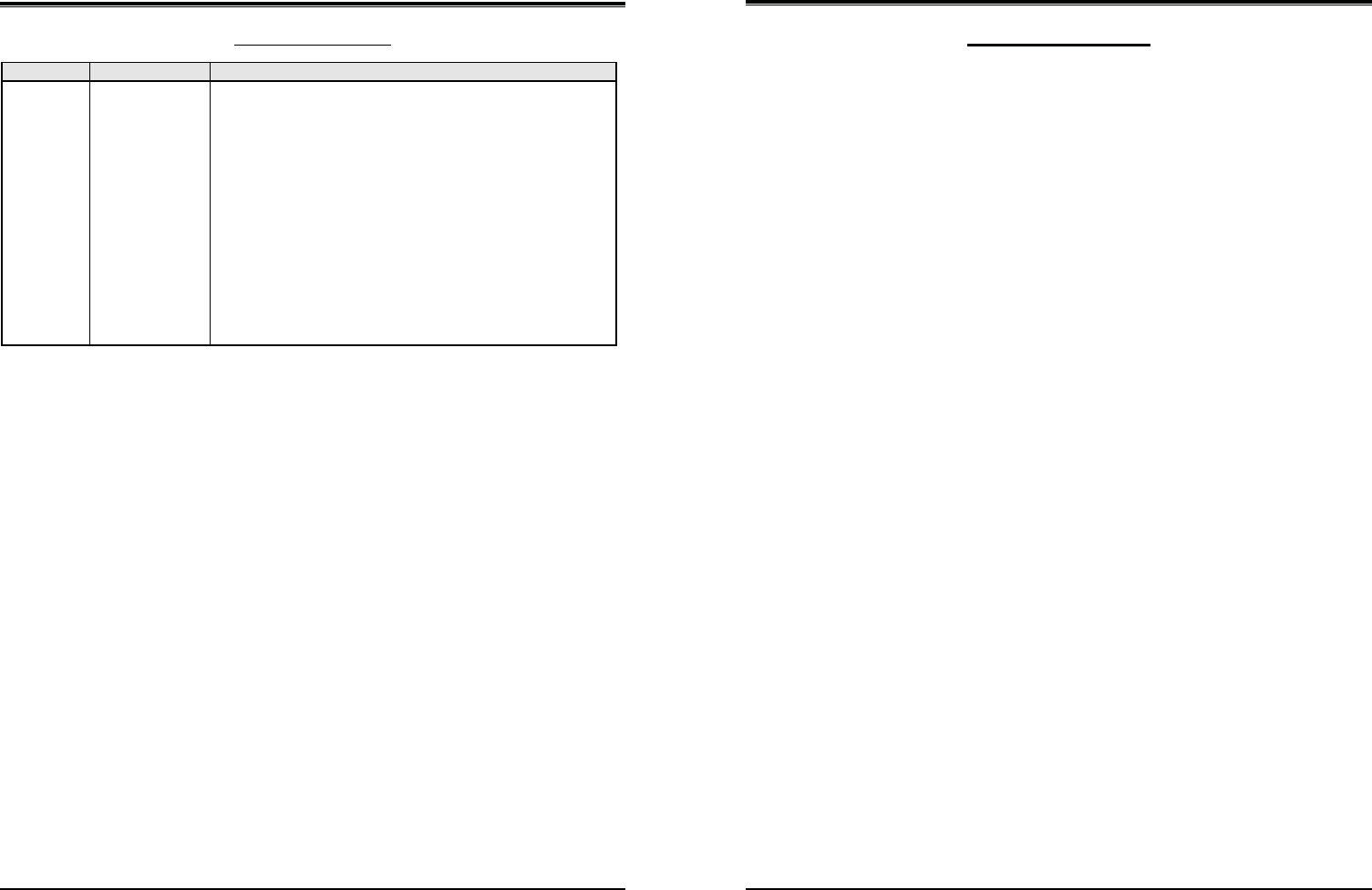
Wireless SOHO
Installation & Operation Manual
Revision History
ISSUE DATE Contents of Changes
1.0
1.1
1.2
Feb. 2010
March 2010
Juluy 2010
Initial release
Revised the text of Menu on LCD and corrected misspelling. And
added to Special note for New Zealand.
Change the new CI (LG-Ericsson)
Wireless SOHO
Installation and Operation Manual
i
Table of Contents
SPECIAL NOTES FOR OPERATION IN NEW ZEALAND …………………. IG
1 INTRODUCTION………………………………………………………………………… 1G
1.1 Manual Usage ………………………………………………………………………………….. 1G
1.2 Package Contents ……………………………………………………………………………. 1G
1.3 Configuration …………………………………………………………………………………… 2G
1.4 System Capability …………………………………………………………………………….. 3G
1.4.1 Description ……………………………………………………………………………………………….…… 3G
1.5 Important Safety Information …………………………………………………………….. 4G
1.5.1 Installation and Environment …………………………………………………………………………… 4G
1.5.2 Electrical Considerations ………………………………………………………………………………… 4G
1.5.3 Precaution ………………………………………………………………………………………………..…… 5G
1.5.4 Caution …………………………………………………………………………………………………..…….. 5G
2 INSTALLATION …………………………………………………………………………. 6G
2.1 Pre-Installation …………………………………………………………………………………. 6G
2.1.1 Safety Installation Instructions …………………………………………………………………………. 6G
2.2 Battery Installation …………………………………………………………………………… 7G
2.2.1 GDC-400H Handset Battery Installation ……………………………………………………………. 7G
2.2.2 GDC-450H Handset Battery Installation ……………………………………………………………. 8G
2.3 LWS-BS, Handset and Peripheral Connections ……………………………….. 10G
2.3.1 FAX Connection …………………………………………………………………………………………… 11G
2.3.2 AC/DC Adapter Connection …………………………………………………………………………… 11G
2.3.3 LWS-WK Connection ……………………………………………………………………………………. 12G
2.3.4 Wireless Handset Connection ……………………………………………………………………….. 12G
2.3.5 Foot Stand Connection (the LWS-BS and LWS-WK) ……………………………………….. 13G
2.4 Hardware Installation ……………………………………………………………………… 15G
2.4.1 Wall Mount of the LWS-BS or the LWS-WK …………………………………………………….. 15G
2.5 Component Description ………………………………………………………………….. 16G
2.5.1 LWS-BS Description …………………………………………………………………………………….. 16G
2.5.2 LWS-WK Description ……………………………………………………………………………………. 17G
2.5.3 Wireless Handset Description ……………………………………………………………………….. 18G
2.6 Hardware Initialization …………………………………………………………………….. 19G
2.6.1 LWS-BS and LWS-WK …………………………………………………………………………………. 19G
2.6.2 Wireless Handset …………………………………………………………………………………………. 19G

Wireless SOHO
Installation and Operation Manual
ii
2.7 Display …………………………………………………………………………………………… 19G
2.7.1 LCD Specification ………………………………………………………………………………………… 19G
2.7.2 LCD Display ………………………………………………………………………………………………... 20G
2.8 Keypad Description ………………………………………………………………………… 22G
2.8.1 LWS-BS ……………………………………………………………………………………………………… 22G
2.8.2 LWS-WK …………………………………………………………………………………………………….. 22G
2.8.3 GDC-400H/450H Wireless Handset ……………………………………………………………….. 23G
2.9 LED Operation Description ……………………………………………………………… 25G
2.9.1 LWS-BS and Wireless Keyset ……………………………………………………………………….. 25G
2.10 Configuration ……………………………………………………………………………….. 26G
2.10.1 Country code …………………………………………………………………………………………….. 26G
2.10.2 LWS-BS Date and Time ……………………………………………………………………………… 27G
2.11 Terminal Registration and Termination ………………………………………….. 27G
2.11.1 Registering the GDC-400H/450H / LWS-WK to LWS-BS ………………………………… 27G
2.11.2 Terminating a Registration…………………………………………………………………………… 29G
2.12 Menu Trees …………………………………………………………………………………… 30G
2.12.1 LWS-BS Menus …………………………………………………………………………………………. 30G
2.12.2 LWS-WK Menus ………………………………………………………………………………………… 30G
2.13 System Capacities ………………………………………………………………………… 31G
3 OPERATION INSTRUCTIONS ………………………………………………….. 32G
3.1 Call Forward …………………………………………………………………………………… 32G
3.2 Call Pick-up ……………………………………………………………………………………. 33G
3.2.1 Directed Call Pick-Up ……………………………………………………………………………………. 33G
3.2.2 Group Call Pick-Up ………………………………………………………………………………………. 33G
3.3 Call Transfer …………………………………………………………………………………… 34G
3.4 Call Waiting/Camp-On …………………………………………………………………….. 35G
3.5 LINE Access …………………………………………………………………………………… 35G
3.6 Three-Party Voice Conference ………………………………………………………… 36G
3.7 Directory ………………………………………………………………………………………… 37G
3.8 DND(Do Not Disturb) ………………………………………………………………………. 37G
3.9 Headset Compatibility …………………………………………………………………….. 38G
3.10 Hold ……………………………………………………………………………………………… 39G
3.10.1 Hold …………………………………………………………………………………………………….……. 39G
3.10.2 Hold Recall ………………………………………………………………………………………………… 40G
Wireless SOHO
Installation and Operation Manual
iii
3.10.3 Automatic Hold ………………………………………………………………………………………….. 40G
3.11 CID Blacklist …………………………………………………………………………………. 40G
3.12 Allowed/Denied Number ……………………………………………………………….. 41G
3.13 MOH (Music-On-Hold) …………………………………………………………………… 41G
3.14 Speed Dial ……………………………………………………………………………………. 42G
3.14.1 Display Security …………………………………………………………………………………………. 42G
3.14.2 Station Speed Dial ……………………………………………………………………………………… 42G
3.14.3 System Speed Dial …………………………………………………………………………………….. 43G
3.15 VSF Integrated Auto Attendant/Voice Mail ……………………………………… 44G
3.15.1 VSF ……………………………………………………………………………………………………..…… 44G
3.15.2 Auto Attendant …………………………………………………………………………………………… 44G
3.15.3 VSF Voice Mail ………………………………………………………………………………………….. 45G
3.16 Wake-Up Alarm …………………………………………………………………………….. 49G
3.17 Intercom Call (ICM Call) ………………………………………………………………… 50G
3.18 Intercom Call Hold ………………………………………………………………………… 51G
3.19 Line Ring Assignment …………………………………………………………………… 51G
3.20 Night/Weekend mode ……………………………………………………………………. 52G
3.21 Call Log Display ……………………………………………………………………………. 52G
3.22 Mute …………………………………………………………………………………………….. 53G
3.23 Tel/Fax Line ………………………………………………………………………………….. 53G
3.24 Feature Code for LWS-BS ……………………………………………………………… 54G
3.25 Feature Code for LWS-WK …………………………………………………………….. 55G
4 USEFUL INFORMATION ………………………………………………………….. 56G
4.1 Trouble shooting ……………………………………………………………………………. 56G
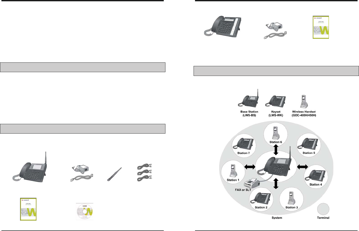
Wireless SOHO
Installation and Operation Manual
1
1
1
I
IN
NT
TR
RO
OD
DU
UC
CT
TI
IO
ON
N
This Installation & Operation Manual is designed to provide general system features and operating
instructions for the LWS (LG-Ericsson Wireless SOHO) System.
This wireless telephone system is compliant to the Digital Enhanced Cordless Telecommunication (DECT)
specification, using carrier frequencies from 1.88GHz to 1.9GHz. It uses Time Division Multiple Access
(TDMA) technology, providing security and protection from eavesdropping.. The system utilises duplex
communication between each handset or keyset via the LWS-BS (base).
1.1 Manual Usage
This document provides general information about the installation, description and operation of the LWS
system. While every effort has been made to ensure the accuracy of this information, LG-Ericsson takes
no responsibility for the accuracy or interpretations thereof.
This section is a functional listing of features with the description and operation of each.
The structure is divided into 3 parts as listed:
z Description: explains the nature of the feature.
z Operation: describes how to use the feature.
z NOTE: explains any requirements or constraints of the feature related to its configuration.
1.2 Package Contents
The LWS-BS includes one (1) base station, one (1) AC/DC power adapter, one (1) AC power cord, one
(1)antenna with rubber ring, three (3) line cords, one (1) ‘Quick User Guide’ and one (1) CD manual.
Please verify that all parts shown below were provided in the package.
LWS—BS Power Adapter Antenna Line cord
(LWS-BS Unit with Foot) AC power cord
Quick User Guide Manual (CD)
Figure 1.2-1 LWS-BS Package Contents
Wireless SOHO
Installation and Operation Manual
2
The LWS-WK includes one (1) wireless keyset, one (1) AC/DC power adapter, one (1) AC power cord, and
one (1) ‘Quick User Guide’. Verify that all parts shown below were provided in the package.
LWS—WK Power Adapter Quick User Guide
(Wireless Terminal) AC power cord
Figure 1.2-2 LWS-WK Package Contents
1.3 Configuration
The following image depicts a sample configuration using LWS-BS system and wireless phones, LWS-WK
and GDC-400H/450H.
Figure 1.3-1 Sample Configuration
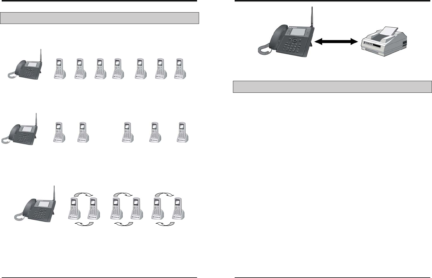
Wireless SOHO
Installation and Operation Manual
3
1.4 System Capability
1.4.1 Description
z Lines: up to 3
z Cordless Handsets: up to seven cordless handsets (provided separately)
Figure 1.4-1 LWS-BS and GDC-400H/450H
External calls (Line calls): up to 3 supported.
Figure 1.4-2 Three (3) External Calls Supported
Internal Calls: Three (3) internal calls can be conducted on six (6) cordless handsets while the LWS-BS
simultaneously makes an external call.
Figure 1.4-3 – Internal Calls Supported
One (1) FAX call or SLT (Single Line Telephone) call can be conducted on the SLT port of the LWS-BS.
LWS-BS
(LWS-BS)
Station 1 Station 2 Station 3 Station 4 Station 5 Station 6 Station 7
External call
on Line 1
External call
on Line 2
External call
on Line 3
External call
on Line 1
External call
on Line 2
External call
on Line 3
OR
External call
on Line x
Wireless SOHO
Installation and Operation Manual
4
Figure 1.4-4 FAX or SLT call via SLT port of the LWS-BS
1.5 Important Safety Information
Read this information before installing your LWS system. Failure to comply with these guidelines could
prove either dangerous or illegal. This information helps to avoid personal injury, damage to the phone,
or other property damage.
1.5.1 Installation and Environment
1. Install all phones according to the manual, failure to do so could affect product functionality.
2. Do not install phones in direct sunlight so as to ensure full product functionality and fire prevention.
3. Do not install in non-ventilated areas such as the inside of a desk or other enclosure so as to
ensure full product functionality and fire prevention.
4. Do not install the phones near appliances such as a TV, refrigerator, vacuum cleaner, audio
equipment etc. which may cause interference and affect voice quality.
5. Do not install the phones in an excessively dusty area so as to ensure full product functionality, fire
and electrical short prevention.
1.5.2 Electrical Considerations
1. Do not overload the electrical outlet with power cords so as to prevent fire or electric shock.
2. Do not touch the plug with wet hands. Failure to comply may cause electric shock.
3. To disconnect any phone from the electrical socket grasp and pull the plug not the cord. Failure to
comply may cause fire or electric shock.
4. Do not cover the phones or place the phones or power adapter near a heating appliance. Failure
to comply may cause fire or electric shock.
5. Do not place objects on the power cord, or allow the power cord to excessively bend. Failure to
comply may cause fire or electric shock.
6. Do not modify or disassemble the power cord. If power cord or plug is impaired, do not use it.
Failure to comply may cause fire or electric shock.
7. Only clean power cord and plug when not plugged into the outlet, by rubbing the cord with a soft
cloth. Failure to comply may cause fire or electric shock.
Wireless SOHO
Installation and Operation Manual
5
1.5.3 Precaution
1. Keep the LWS-BS, the LWS-WK and DECT terminals away from heating appliances and electrical
noise generating devices such as fluorescent lamps microwave ovens and televisions. These
noise sources can interfere with the performance of the LWS system.
2. This system should be kept free of dust, moisture, high temperature (more than 40 degrees) and
vibration, and should not be exposed to direct sunlight.
3. To Clean the LWS-BS, the LWS-WK and DECT Terminals, wipe with a soft cloth only. Do not use
benzene, paint thinner, or an abrasive cleansing powder as these may cause damage to the
system and possible fire or electric shock.
1.5.4 Caution
1. If the product casing is broken, disconnect the power supply cord immediately and return the system to
your dealer.
WARNING
Replace batteries only with the same or equivalent type recommended by the manufacturer.
Dispose of used batteries according to the manufacturer’s instructions.
Wireless SOHO
Installation and Operation Manual
6
2
2
I
IN
NS
ST
TA
AL
LL
LA
AT
TI
IO
ON
N
2.1 Pre-Installation
Please read the following guidelines concerning installation and connection before installing the LG-
Ericsson Wireless SOHO System. Be sure to comply with any applicable local regulations.
(Note: telephone extension cabling must be performed by local regulatory each country registered installer).
2.1.1 Safety Installation Instructions
When installing telephone wiring, basic safety precautions should always be followed to reduce
the risk of fire, electric shock and personal injury:
1. Never install telephone wiring during a lightning storm.
2. Never install a telephone jack in wet locations unless the jack is specifically designed for a wet
environment.
3. Never touch un-insulated telephone wires or terminals unless the telephone line has been
disconnected.
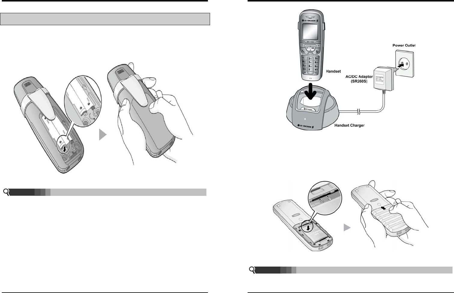
Wireless SOHO
Installation and Operation Manual
7
2.2 Battery Installation
2.2.1 GDC-400H Handset Battery Installation
To install a Battery to the Handset:
1. Remove the battery cover by pressing the latch as shown, and slide down to open.
2. Verify batteries are orientated correctly for polarity when inserting.
3. Close the battery cover and slide it upward until it clicks into place.
Figure 2.2.1-1 Handset Battery Installation
¾ Purchase new batteries from your LG-Ericsson Service Center.
¾ The battery has a limited operating life (warranty period for the battery is 6 months from
purchase date).
2.2.1.1 GDC-400H Battery Charging
To charge the handset:
1. Place handset on the plugged-in charger for 12 hours before initial use.
NOTE:
Wireless SOHO
Installation and Operation Manual
8
Figure 2.2.1.1-1 GDC-400H Handset Battery Charging
2.2.2 GDC-450H Handset Battery Installation
To install a Battery to the Handset:
1. Remove the battery cover by pressing the latch as shown, and slide down to open.
2. Verify batteries are orientated correctly for polarity when inserting.
3. Close the battery cover and slide it upward until it clicks into place.
Figure 2.2.2-1 GDC-450H Handset Battery Installation
¾ Purchase new batteries from your LG-Ericsson Service Center.
¾ The battery has a limited operating life (warranty period for the battery is 6 months from
purchase date).
NOTE:
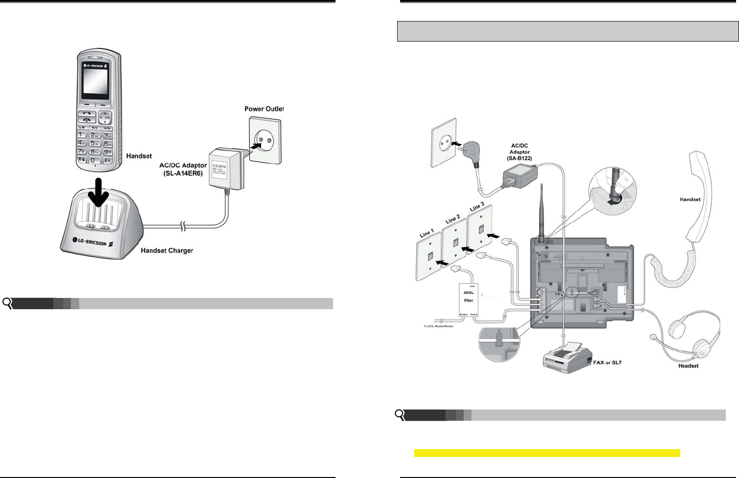
Wireless SOHO
Installation and Operation Manual
9
2.2.2.1 GDC-450H Battery Charging
To charge the handset:
1. Place handset on the plugged-in charger for 12 hours before initial use.
Figure 2.2.2.1-1 GDC-450H Handset Battery Charging
¾ The GDC-450H uses an advanced battery charging technology, the battery level is reviewed
every 6 hours causing red recharge light to illuminate briefly.
NOTE:
Wireless SOHO
Installation and Operation Manual
10
2.3 LWS-BS, Handset and Peripheral Connections
To connect the LWS-BS with phone lines and its peripherals:
1. Connect the line cords to the ports on the bottom of the LWS-BS and the other ends to the wall
sockets.
2. Plug the AC/DC Adapter cord and FAX/SLT Line into the bottom of the LWS-BS.
3. Connect the handset curly cord to the handset jack on the bottom of the LWS-BS.
4. Connect the optional Headset to the headphone jack on the bottom of the LWS-BS.
5. Screw the included rubber antenna clockwise onto the terminal at right side of the top of the
LWS-BS.
Figure 2.3-1 LWS-BS Connections
¾ Use only the included LG-Ericsson AC Adapter (SA-B122).
¾ Using a headset with the LWS-BS is optional.
¾ Avoid mounting near a TV, another cordless telephone or a microwave oven.
¾ To reduce the risk of fire, use only No. 26 AWG or larger telecommunication line cord
NOTE:
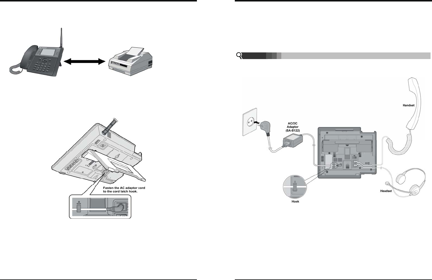
Wireless SOHO
Installation and Operation Manual
11
2.3.1 FAX Connection
The following figure illustrates how to connect a FAX to the LWS-BS:
2.3.2 AC/DC Adapter Connection
To connect the AC/DC adapter:
1. Plug the DC outlet of the AC/DC Adapter cord into the jack on the LWS-BS.
2. Fasten the AC/DC Adapter cord to the latch hook as shown (inset detail).
Figure 2.3.2-1 AC/DC Adapter Connection
Wireless SOHO
Installation and Operation Manual
12
2.3.3 LWS-WK Connection
To connect the LWS-WK to be used with the LWS-BS:
1. Plug the DC outlet of the AC/DC Adapter cord into the jack on the LWS-WK.
2. Fasten the AC/DC Adapter cord to the latch hook as shown (inset detail).
3. Connect the handset curly cord to the handset jack on the bottom of the LWS-WK.
4. Connect the optional headset to the headset jack on the bottom of the LWS-WK)
¾ Use only the included LG-Ericsson AC Adapter (SA-B122).
¾ Using a headset with the LWS-WK is optional.
¾ Avoid mounting near TV and another cordless telephone, microwave oven, or personal
computers and other electrical equipment.
Figure 2.3.3-1 LWS-WK Connection
2.3.4 Wireless Handset Connection
To connect a Wireless Handset to be used with the system:
1. Plug in the AC adapter cord to the Handset Charger and plug AC outlet to the power outlet.
2. Use only the included LG-Ericsson AC/DC adapter, which is provided together with GDC-
400H/450H. It is dependent on the country to provide the AC/DC adapter.
NOTE:
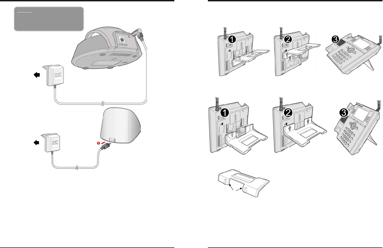
Wireless SOHO
Installation and Operation Manual
13
Figure 2.3.4-1 Wireless Handset Charger Connection: GDC-400H
Figure 2.3.4-2 Wireless Handset Charger Connection: GDC-450H
2.3.5 Foot Stand Connection (the LWS-BS and LWS-WK)
Warning
Use only the main power adapter
supplied. Any other adapter could
damage your GDC-400H and invalid
ate your warranty
2. To AC OUTLET
1. Adaptor
Wireless SOHO
Installation and Operation Manual
14
When the Foot Stand to either the LWS-BS or the LWS-WK is attached, it can be connected at a 35
or 55 degree angle.
To connect the Foot Stand at a 35 degree angle, perform the following:
Figure 2.3.5-1 Foot Stand Connection (35 degree angle)
To connect the Foot Stand at a 55 degree angle, perform the following:
Figure 2.3.5-2 Foot Stand Connection (55 degree angle)
1. Align the top tabs on the foot stand with the slots on the back of the LWS-BS or the LWS-WK.
2. Move the foot stand upward until it clicks into place.
Top tap
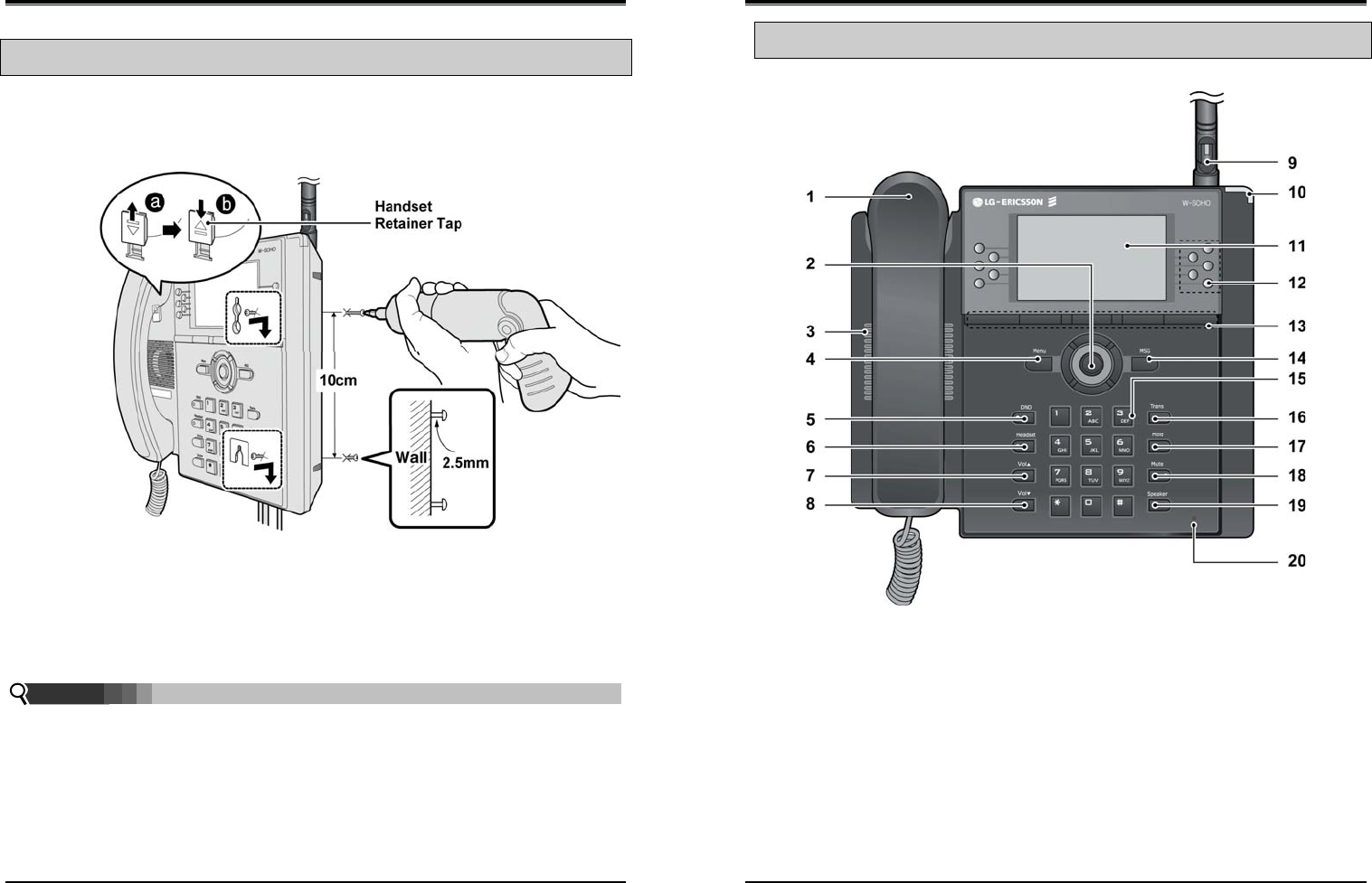
Wireless SOHO
Installation and Operation Manual
15
2.4 Hardware Installation
2.4.1 Wall Mount of the LWS-BS or the LWS-WK
To wall mount the LWS-BS or LWS-WK, perform the following:
1. Remove the foot stand.
2. Make sure the handset retainer tab is positioned at ‘b’ as shown below figure.
Figure 2.4.1-1 Wall Mount of LWS-BS/ LWS-WK
3. Make a small mark on the wall where you want the top keyhole slot to align and install a screw (not
provided) so that it protrudes slightly, approx. 2.5mm, from the wall (Figure shown).
4. Measure a straight line down 10cm from the mark, and install another screw (not provided).
5. Align the keyholes on the back of the phone with the screws in the wall, and then slide the phone
down on the screws to secure the phone.
¾ Ensure all cables are properly routed and if necessary, that power should be installed before
affixing to the wall mount screws.
Note:
Wireless SOHO
Installation and Operation Manual
16
2.5 Component Description
2.5.1 LWS-BS Description
1. Handset 2. Navigation/OK Key
3. Speaker 4. Menu Button
5. DND Button 6. Headset Button
7. Volume Up Button 8. Volume Down Button
9. Antenna 10. Ring Indication Light
11. LCD 12. Line/Station Selection Buttons
13. Soft Buttons 14. MSG (Message) Button
15. Dial Buttons 16. Transfer Button
17. Hold Button 18. Mute Button
19. Speaker Button 20. Microphone
Figure 2.5.1-1 LWS-BS Component Description
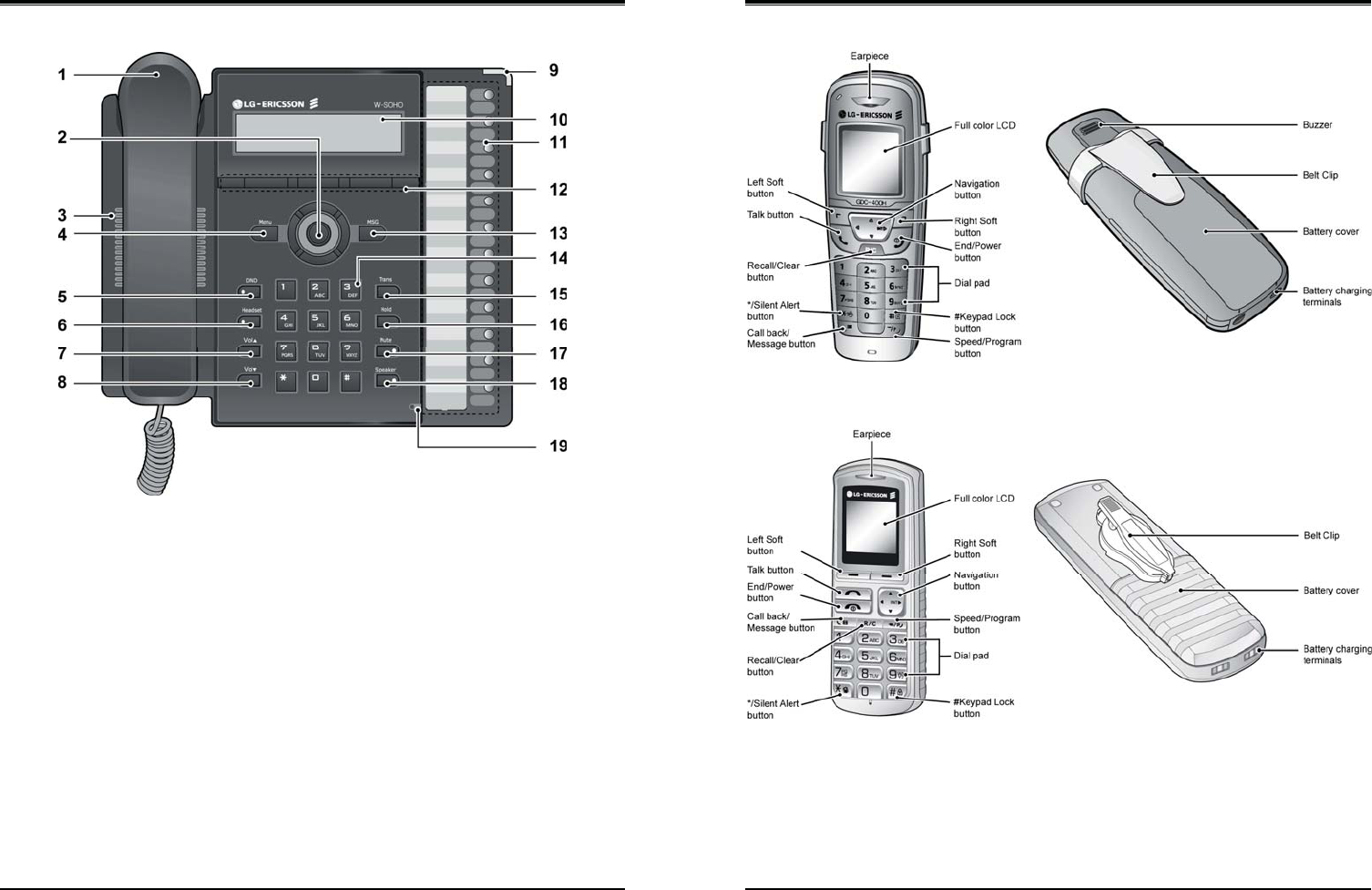
Wireless SOHO
Installation and Operation Manual
17
2.5.2 LWS-WK Description
1. Handset 2. Navigation/OK Key
3. Speaker 4. Menu Button
5. DND Button 6. Headset Button
7. Volume Up Button 8. Volume Down Button
9. Ring Indication 10. LCD
11. Line/Station Selection Buttons 12. Soft Buttons
13. MSG Button 14. Dial Buttons
15. Transfer Button 16. Hold Button
17. Mute Button 18. Speaker Button
19. Microphone
Figure 2.5.2-1 LWS-WK Component Description
Wireless SOHO
Installation and Operation Manual
18
2.5.3 Wireless Handset Description
Figure 2.5.3-1 GDC-400H Component Description
Figure 2.5.3-2 GDC-450H Component Description
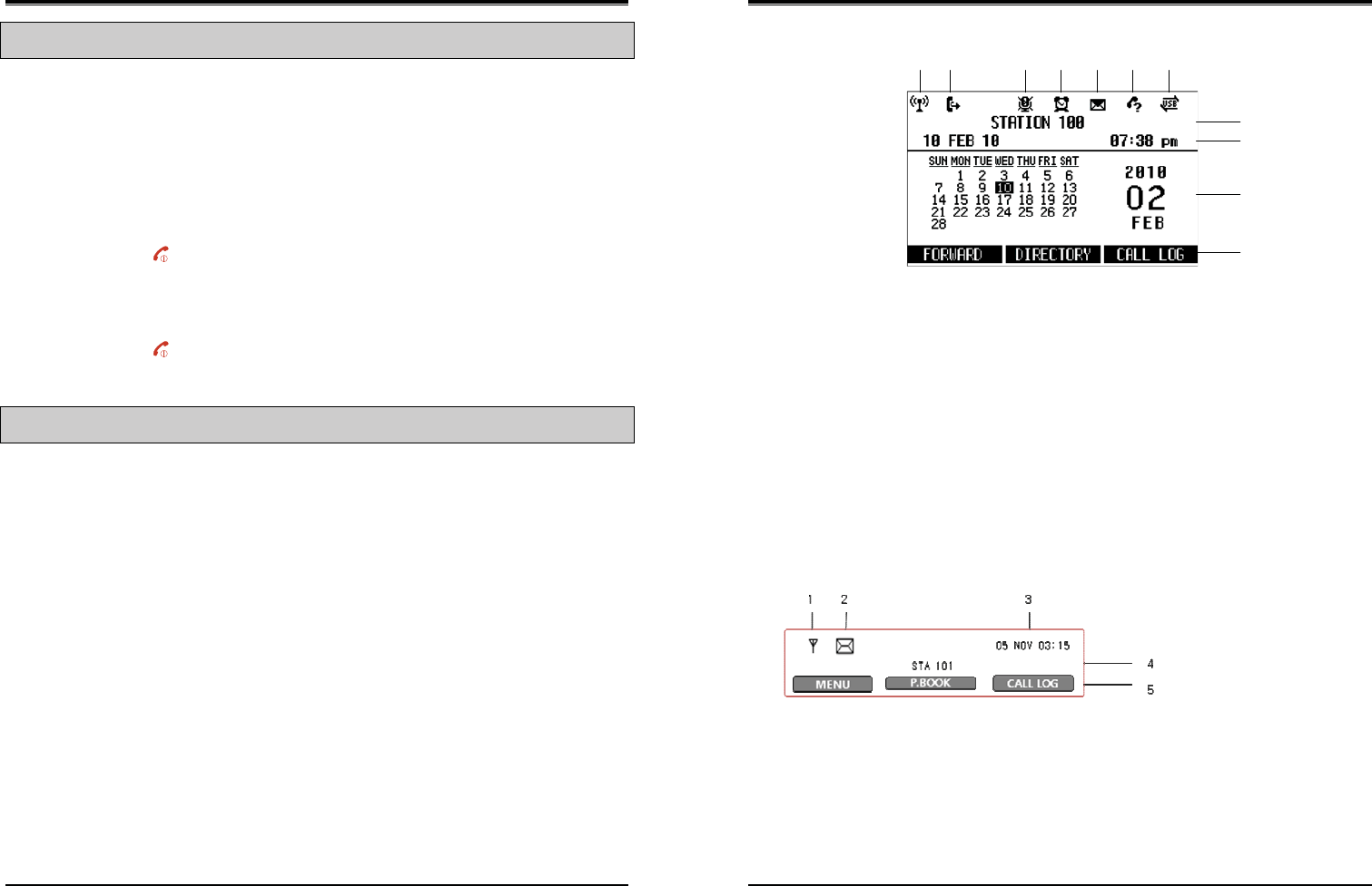
Wireless SOHO
Installation and Operation Manual
19
2.6 Hardware Initialization
2.6.1 LWS-BS and LWS-WK
Once the LWS-BS and the LWS-WK have been properly installed in the desired locations, perform the
following:
1. Plug in the AC/DC adapter to the LWS-BS or the LWS-WK (use only the included AC/DC adapter,
SA-B122).
2. The LWS-BS or the LWS-WK is powered up and its display on the LCD will be activated.
2.6.2 Wireless Handset
To start up the Handset:
1. Press and hold [ ] for approximately 2 seconds.
2. The handset automatically enters standby mode when a signal is located.
3. The handset automatically returns to standby mode whenever it is placed on the charger.
To power-down the Handset:
1. Press and hold [ ] for approximately 3 seconds.
2.7 Display
2.7.1 LCD Specification
User can select one of backlight control options (always on, always off, busy state on).
2.7.1.1 LWS-BS
z 240 x 144 Graphic LCD
z Backlit On/Off Control with 3 selectable option
z Ten-Level Contrast Setting
2.7.1.2 LWS-WK
z 240 x 42 Graphic LCD
z Backlight On/Off Control
z Ten-Level Contrast Setting
Wireless SOHO
Installation and Operation Manual
20
2.7.2 LCD Display
2.7.2.1 LWS-BS
Figure 2.7.2.1-1 the LWS-BS LCD Display Screen
1. Antenna — Displayed when DCTU of LWS-BS works and it can be linked to DECT .
2. Call Forward – Icon indicates the base station is currently set for call forwarding.
3. Mute – Icon indicates if the mute button is activated for blocking voice transmission on your phone
during a conversion.
4. Alarm – Icon indicates the alarm has been set.
5. Message – Icon indicates there is at least one new message.
6. Missed call – Icon indicates that there are missed calls in your absence.
7. USB – Icon indicates a USB memory device is inserted.
8. Station Number – Displayed in idle state. If the LWS-BS station has the designated name, the
name is displayed.
9. Date & Time – Displayed in idle state.
10. Calendar – Displayed in idle state.
11. Soft Menu – Dependent on the status and menu choices, the current available selections are
displayed.
2.7.2.2 LWS-WK
1. Antenna — Displayed when the LWS-WK is in the range of a LWS-BS where it can be linked.
Disappears when it moves out of range. The closer it moves to the base, the stronger RSSI for
reception is.
2. Message – Icon indicates there is at least one new message.
3. Date & Time –Displayed in idle state.
4. Keyset Number – Displayed in idle state.
5. Soft Menu – Dependent on the status and menu choices, the current available functions are
displayed.
1 2 34567
8
9
10
11
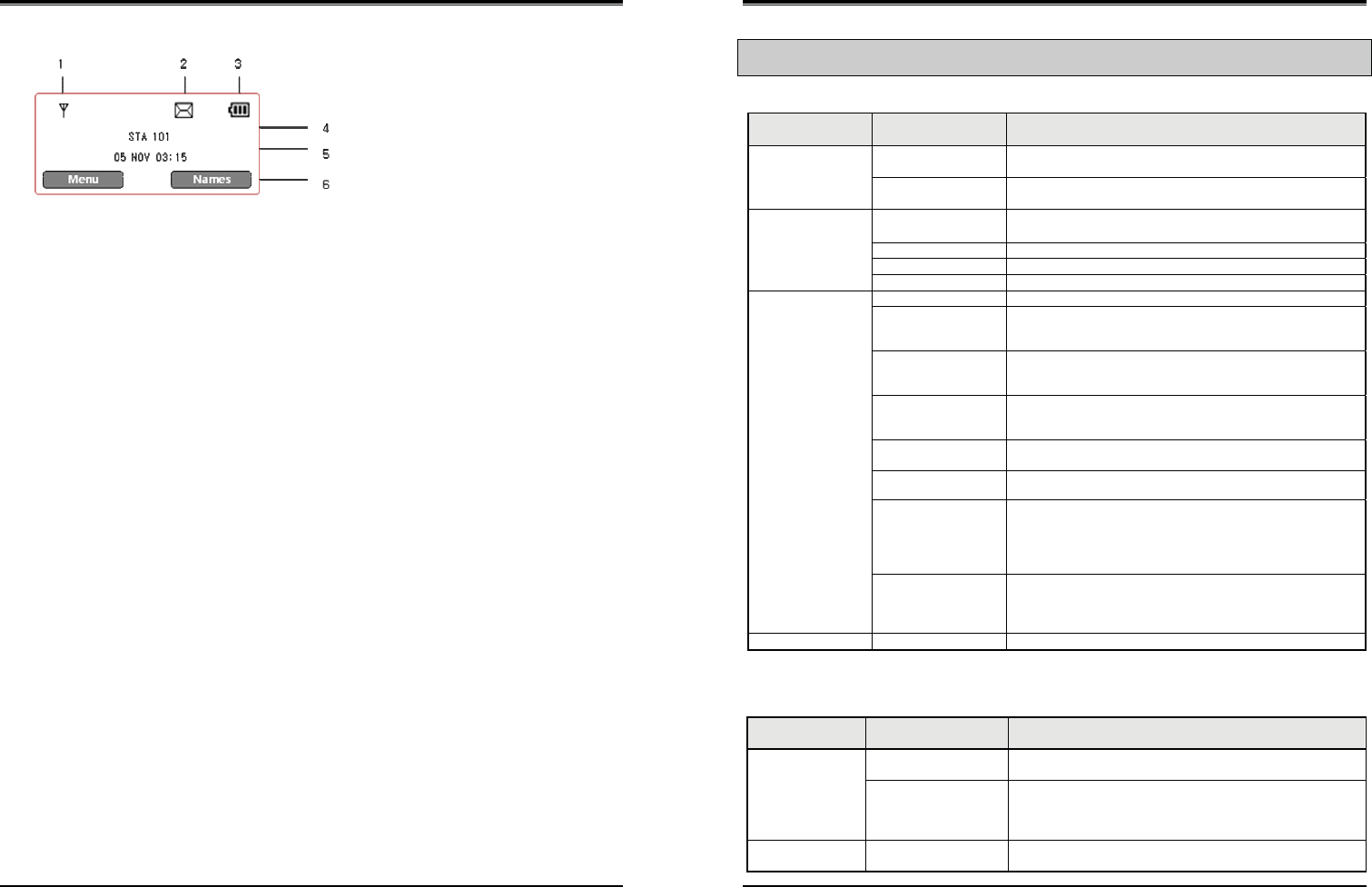
Wireless SOHO
Installation and Operation Manual
21
2.7.2.3 GDC-400H and GDC-450H Wireless Handset
1. Antenna — Displayed when the handset is in the range of a LWS-BS where it can be linked.
Disappears when it moves out of range. The closer it moves to the base, the stronger RSSI for
reception is.
2. Message – Icon indicates there is at least one new message.
3. Date & Time – Displayed in idle state.
4. Battery – Displays battery level when a handset keeps operating.
5. Handy Number – Displayed in idle state.
6. Soft Menu – Dependent on the status and menu choices, the current available functions are
displayed.
Wireless SOHO
Installation and Operation Manual
22
2.8 Keypad Description
2.8.1 LWS-BS
FUNCTIONAL
CLASSIFICATION BUTTON NAME BUTTON DESCRIPTION
Flex Keys Line selection button
Line 1 ~ 3
Access an idle Line for making external call or answer the
incoming call by pressing the line button.
Station button
Station 101~107
Allows you to make an intercom call.
Station 101~107 : Wireless Terminals
Soft Menu Keys Soft key 1,2,3 Dependent on the status and menu choices, the current
available functions are displayed.
Menu Main Menu
MSG Retrieve Messages
Navigation button Up/down/right/left/ok
Function Keys DND Set Night/Weekend mode
Headset Headset mode or speakerphone mode is switched by pressing
the [Headset] button in idle state. Headset LED will be
illuminated when headset mode is selected.
Vol. up To turn Handset or Speaker volume up during a call/off hook.
Ringer volume is turned up if phone is ringing. LCD contrast is
turned up if phone is in idle state.
Vol. down To turn Handset or Speaker volume down during a call/off
hook. Ringer volume is turned down if phone is ringing. LCD
contrast is turned down if phone is in idle state.
Trans An intercom call or line call can be transferred to another
station or line during a conversation.
Hold When on a call, the station user can place an active call on
hold; the held party will hear a hold tone.
Mute During a conversation, pressing the [MUTE] button will disable
the handset microphone or the speakerphone whilst
continuing to listen to the other party. Pressing the [MUTE]
button again, will reactivate the microphone. This button is
active on all calls.
Speaker Pushing the [Speaker] button allows the user to make or
continue a call using the Speaker for two-way communication.
Pressing the [Speaker] button again, will terminate the call.
EXIT on Menu
Dial Pad 0~9, *, # Use to dial a number, select a menu item, or input values.
2.8.2 LWS-WK
FUNCTIONAL
CLASSIFICATION BUTTON NAME BUTTON DESCRIPTION
Flex Keys Line selection button
Line 1 ~ 3
Access an idle Line for making an external call or answer
the incoming call by pressing Line button.
Station button
Station 100~108
Allows you to make an intercom call.
Station 100 : Base Station
Station 101~107 : Wireless Terminals
Station 108 : SLT/FAX
Soft Menu Keys Soft key 1,2,3 Dependent on the status and menu choices, the current
available functions are displayed.
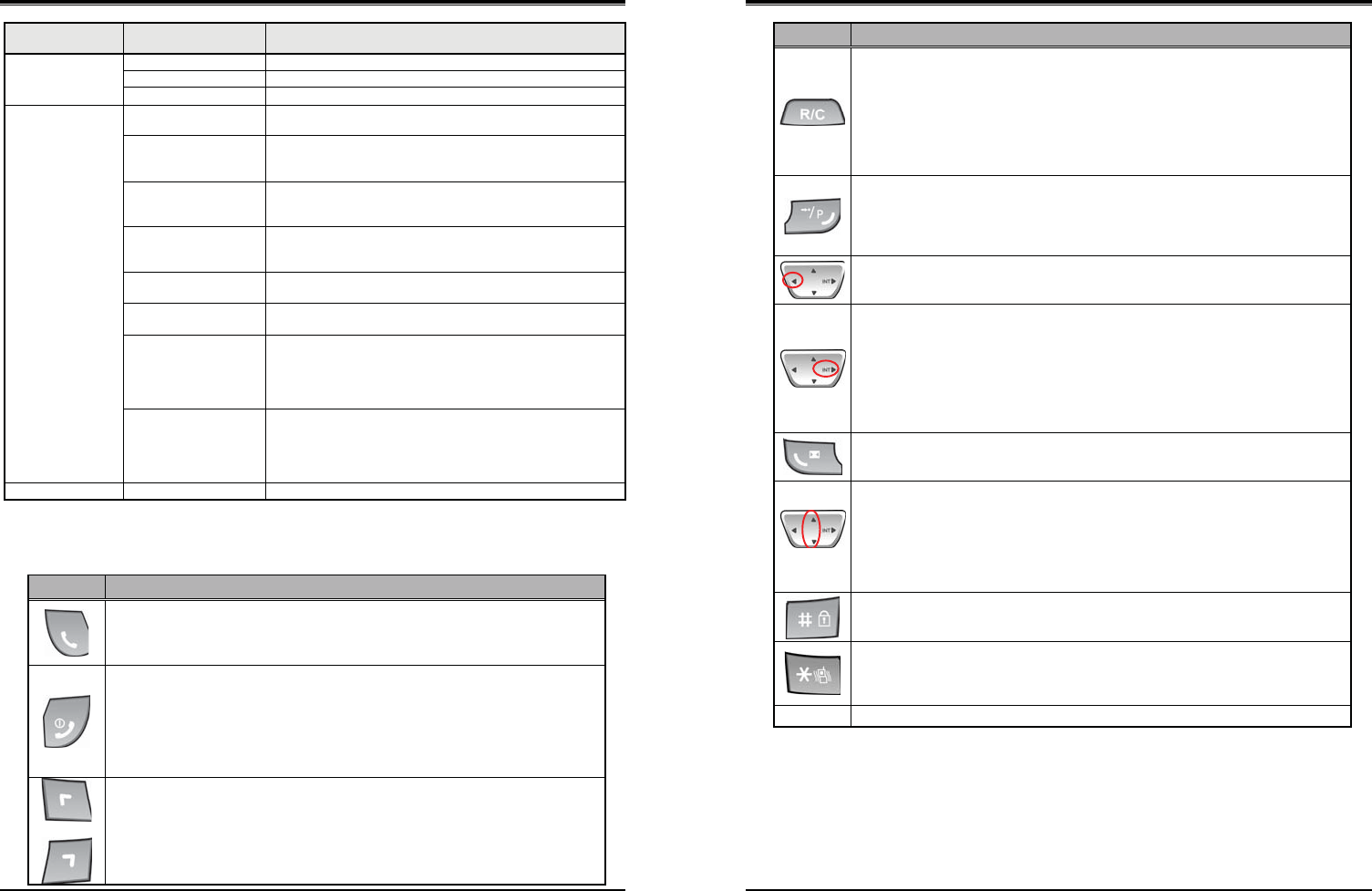
Wireless SOHO
Installation and Operation Manual
23
FUNCTIONAL
CLASSIFICATION BUTTON NAME BUTTON DESCRIPTION
Menu Main Menu
MSG Retrieve Messages
Navigation button Up/down/right/left/ok
Function Keys DND Blocks incoming calls ringing. This applies to outside calls,
intercom calls and transfers
Headset Connecting an optional headset to the station allows
hands-free conversations by pressing [Headset] button.
An industry standard headset can be connected to a station
Vol. up To turn Handset or Speaker volume up during a call/off hook.
Ringer volume is turned up if phone is ringing. LCD contrast is
turned up if phone is in idle state.
Vol. down To turn Handset or Speaker volume down during a call/off
hook. Ringer volume is turned down if phone is ringing. LCD
contrast is turned down if phone is in idle state.
Trans An intercom call or a line call can be transferred to another
station or line during a conversation.
Hold When on a call, the station user can place an active call on
hold; the held party will hear a hold tone.
Mute During a conversation, pressing the [MUTE] button will
disable the handset microphone or the speakerphone whilst
continuing to listen to the other party. Pressing the [MUTE]
button again, will reactivate the microphone. This button is
active on all calls.
Speaker Pushing the [Speaker] button allows the User to make or
continue a call using the Speaker for two-way communication.
Pressing the [Speaker] button again, will deactivate the
Speaker, and send call transmission to the handset (if in use)
or terminate the call.
Dial Pad 0~9, *, # Use to dial a number, select a menu item, or input values.
2.8.3 GDC-400H/450H Wireless Handset
Button Function
[TALK]
To make a call
Î Redial number saved in handset.
[END/POWER]
END/POWER]
To end a call
Press for less than 1 second : Power Off
Press for less than 1 second :Leave a call back or a message
Press for less than 1 second: Ignore an incoming call.
[LEFT SOFT / RIGHT SOFT]
Access to the current functions by pressing the soft button directly below this
symbol.
Wireless SOHO
Installation and Operation Manual
24
Button Function
[RECALL/CLEAR]
Talk Mode : Register recall
Recall a call and retry next call
When using pre-dial :
Î Press for longer than 1 second : All digits are cleared
Î Press for less than 1 second : 1 digit backspace
Î When using local functional operation : Function cancel
(It should be pressed for longer than 1 second)
[SPEED/PROGRAM]
Post-Dial :
Î Press for less than 1 second: System speed dial(SPEED).
Î Press for longer than 1 second: Start/Finish a system program
(PROGRAM).
[LEFT]
In an idle state : To view missed call
In MENU : LEFT
[RIGHT/INTERNAL/TRANSFER/HOLD]
Talking Mode :
Î Press for less than than 1 second: Transfer a call to another
station(TRANS).
Î Press for longer than 1 second: Hold a call / release a holding call(HOLD).
In an idle state :
Î In MENU : right button
Î To make a intercom call or a line call
[CALL BACK]
Press less than 1 second : Leave a call back or a message
G
[UP/DOWN]
Talk Mode : Up / Down the level of Rx volume, Call by name, CLIP
Standby Mode :
Î In Menu: Navigate and select among function items in a menu or submenu.
No inputted state :
Î UP : Local Redial
Î DOWN : Phonebook list
To lock Keypad (Press for longer than 1 second)
‘#’ Display (Press less than 1 second)
While Dialing: To insert pause (Press for longer than 1 second)
G
Talk Mode : Camp-On
Standby Mode :
Î ‘*’ is displayed (Press for shorter than 1 second)
Î Enable/disable manner mode(Press for less than 1 second)
0~9 — Standard dial button
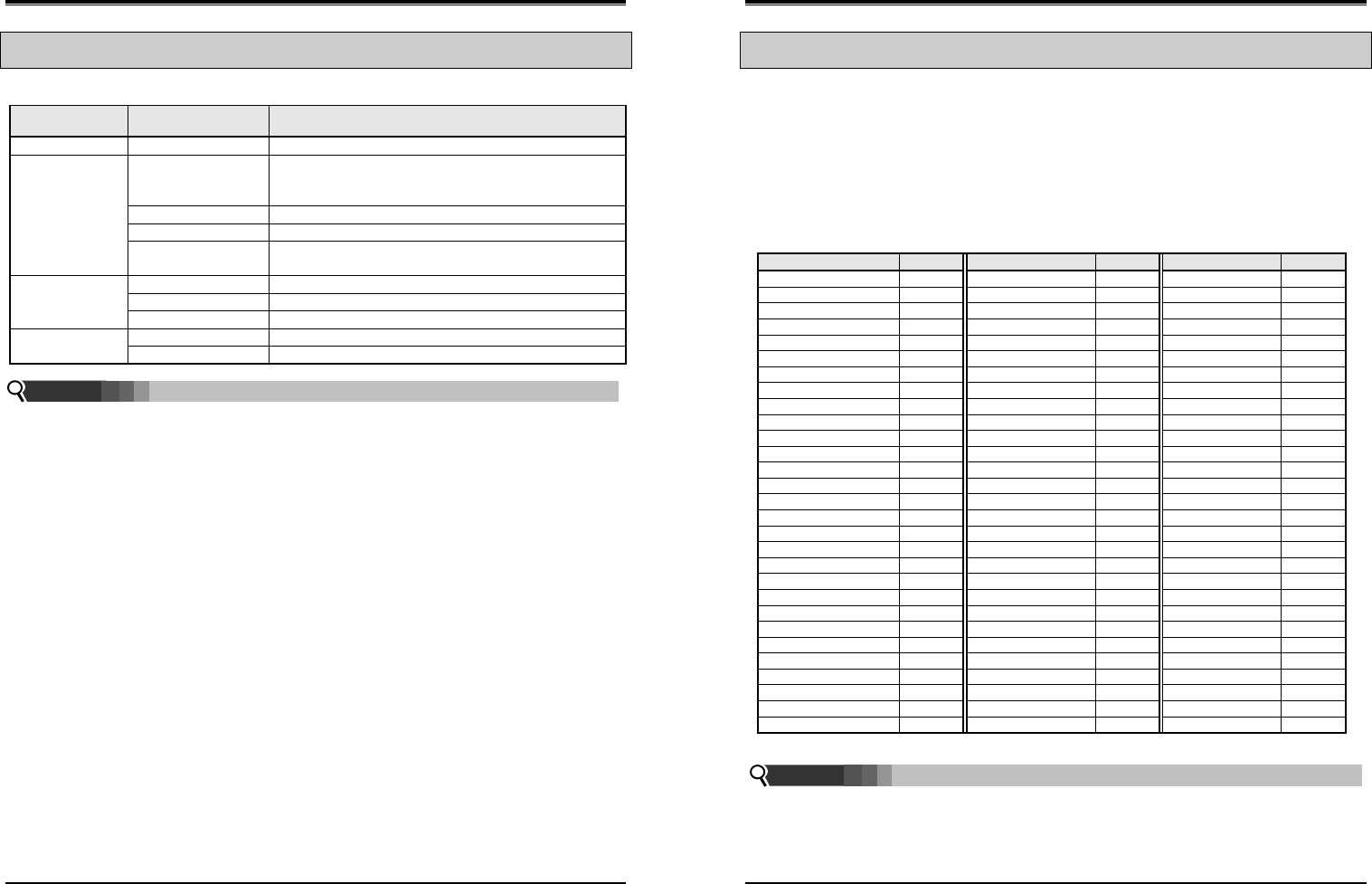
Wireless SOHO
Installation and Operation Manual
25
2.9 LED Operation Description
2.9.1 LWS-BS and Wireless Keyset
FUNCTIONAL
CLASSIFICATION LED OPERATION LED DESCRIPTION
Ring Indicator RED Blink Indicates incoming ring signal
Line Selection
Button
Green/RED Blink Line is in hold state
Green blink: Line is held by the own station
Red blink: Line is held by others
Orange Blink Indicates ringing state
Green steady on The green LED illuminates when you are on a call
Red steady on The red LED indicates that the associated line is in use by
other user
Station Selection
Button
ON (RED) Illuminates when you or others are on a call
Red Blink Ringing state indication
OFF Idle State
DND, Headset
Mute, Speaker
ON Illuminates when each function is activated.
OFF Function is deactivated
Blinking rate:
z Base Station : 0.5/sec.
z Wireless Keyset : 0.78/sec.
Note:
Wireless SOHO
Installation and Operation Manual
26
2.10 Configuration
2.10.1 Country code
To set the nation code, perform the following:
1. Press the [Menu] button on the LWS-BS.
2. Select 1. CONFIGURATION > 2. COUNTRY.
3. If you want to change country, press [CHANGE] soft key or [OK] Navigation key.
4. Set the Country code (refer to the blow Nation Code Table).
5. When finished, press the [SAVE] button, and system will ask you to confirm it.
6. If you select [YES] as pressing digit 1, system will restart and database will be initialized.
Nation Code Table
NATION CODE NATION CODE NATION CODE
America 1 Argentina 54 Australia 61
Bahrain 973 Bangladesh 880 Belgium 32
Bolivia 591 Brazil 55 Brunei 673
Burma 95 Cameroon 237 China 56
China (Taiwan) 886 CIS 7 Colombia 57
Costa Rica 506 Cyprus 357 Czech 42
Denmark 45 Ecuador 593 Egypt 20
El Salvador 503 Ethiopia 251 Fiji 679
Finland 358 France 33 Gabon 241
Germany 49 Ghana 233 Greece 30
Guam 671 Guatemala 502 Guyana 592
Haiti 509 Honduras 504 Hong Kong 852
India 91 Indonesia 62 Iran 98
Iraq 964 Ireland 353 Israel 972
Italy 39 Japan 81 Jordan 962
Kenya 254 Korea 82 Kuwait 965
Liberia 231 Libya 218 Luxembourg 352
Malaysia 60 Malta 356 Mexico 52
Monaco 377 Morocco 212 Netherlands 31
New Zealand 64 Nigeria 234 Norway 47
Oman 968 Pakistan 92 Panama 507
Papua New Guinea 675 Paraguay 595 Peru 51
Philippines 63 Portugal 351 Qatar 974
Saudi Arabia 966 Senegal 221 Singapore 65
South Africa 27 Spain 34 Sri Lanka 94
Swaziland 268 Sweden 46 Switzerland 41
Thailand 66 Tunisia 216 Turkey 90
United Arab Emirates 971 United Kingdom 44 Uruguay 598
Venezuela 58 Vietnam 84 Yemen 967
¾ It is recommended that the Country code is configured to enable proper operation of the LWS-BS
according to the specific country.
Note:
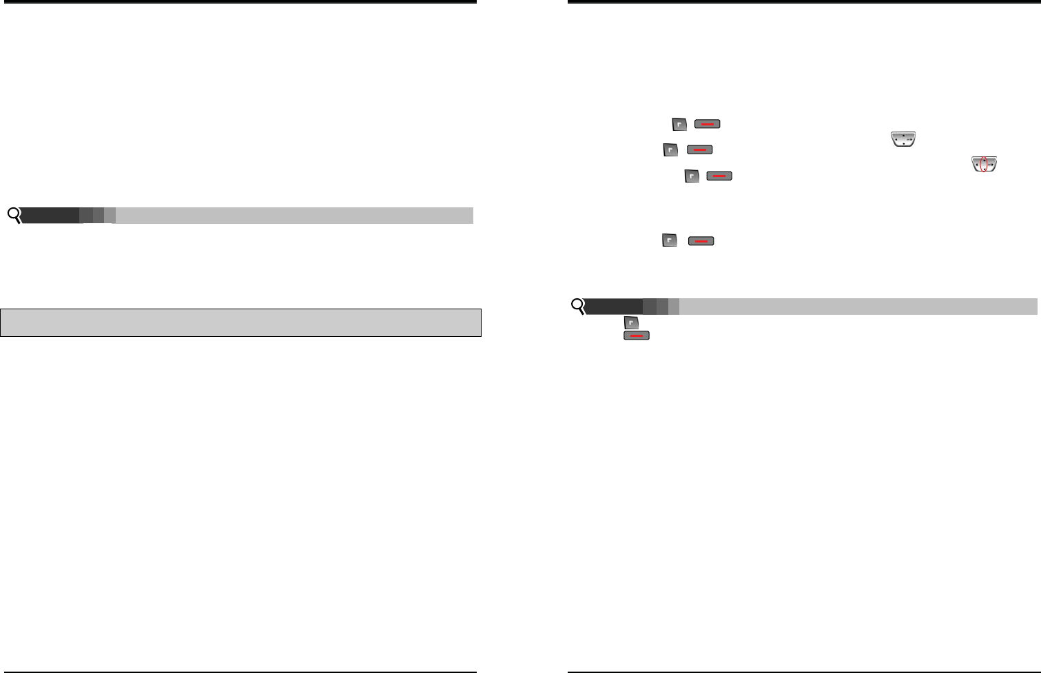
Wireless SOHO
Installation and Operation Manual
27
2.10.2 LWS-BS Date and Time
The Base Date and Time can be set and adjusted by the User.. In the event of a power failure, the system
will retain Date and Time including Database with internal Lithium Battery. All wireless keysets registered
to the Base Station will automatically adjust Date and Time according to the Base Station value after
pressing Talk key or Speaker button.
To set the Date & Time:
1. With the LWS-BS in idle state, press the [Menu] button.
2. Select 1. CONFIGURATION > 1. DATE / TIME.
3. In this menu, set the Date and Time by entering the desired values using the keypad and scrolling
with the navigation arrow keys.
4. When finished, press the [SAVE] soft key or press the [OK] button Navigation key and a
confirmation tone will be heard.
¾ Date and Time of Wireless Keysets (LWS-WK) and Wireless Handsets (GDC-400H and GDC-
450H), are automatically updated by the LWS-BS after pressing Talk key or Speaker button
so there is no need to set the date and time on these.
2.11 Terminal Registration and Termination
The LWS-BS controls the functional service and registration related to the LWS-WK and GDC-400H/450H
including a registration function. Each LWS-WK and GDC-400H/450H must be registered to the LWS-BS (Base
Station) before use.
2.11.1 Registering the GDC-400H/450H / LWS-WK to LWS-BS
Only one Wireless Handset or Keyset can be registered at a time.
2.11.1.1 Enabling Registrations
To enable a registration, the below procedure must be performed on the LWS-BS.
1. Press [Menu] button.
2. Press [Digit 1] (CONFIGURATION submenu), or
Select [1. CONFIGURATION] using the Navigation up/down key and then press [OK] soft but
ton or Navigation ‘OK’ key.
3. Press [Digit 4] (STATION REGISTRATION submenu), or
Select [4. STATION REGISTRATION] using the Navigation up/down key and then press [OK]
soft button or Navigation ‘OK’ key.
4. Press [Digit 1] (REGISTER STATION submenu), or
Select [1. REGISTER STATION] using the Navigation up/down key and then press [OK] soft
button or Navigation ‘OK’ key.
5. Select the phone type using the Navigation left/right key (GDC-4XX or LWS-WK)
6. Press Navigation [OK] button or [OK] soft key.
7. Proceed to instructions below — “Registering GDC-400H/450H to the LWS-BS” or “Registering
Note:
Wireless SOHO
Installation and Operation Manual
28
LWS-WK to the LWS-BS.
8. When the registration is completed, below message is shown on the LCD of the LWS-BS.
STATION: 10X
SUBSCRIBED: SUCCESS
2.11.1.2 Registering GDC-400H/450H to the LWS-BS
To register to the LWS-BS, the below procedure must be performed on the GDC-400H/450H.
1. Press [Menu] ( , ) button to display the menu.
2. Highlight [Phone Register] in the menu using the Navigation ( ) button.
3. Press [OK] ( , ) button; then the Phone Register menu will be displayed.
4. Select [LWS Subscription] using the up and down arrows of the Navigation ( ) button
and press [OK] ( , ) button.
5. Display [Searching.1].
6. The system [RFPI : eg. 01234567890123] will be displayed when a system is found.
The RFPI of your system is available from your System Administrator, or perhaps the attend-
ant.
7. Press [OK] ( , ) button; in a few seconds, a confirmation tone will be heard at the
GDC-400H/450H.
8. If the registration fails, repeat the procedure from Step 1 to 7 at the LWS-BS and Step 1 to
7 from the GDC-400H/450H.
¾ : [Menu], [OK] button on GDC-400H
¾ : [Menu], [OK] button on GDC-450H
¾ RFPI : Radio Fixed Part Identity
¾ Seven Wireless Handsets and/or Keysets can be registered to one LWS-BS.
2.11.1.3 Registering LWS-WK to the LWS-BS
To register to the LWS-BS, below procedure is performed on the LWS-WK.
1. Press [Menu] button to display the menu.
2. Highlight [Phone Register] using the Navigation up/down key, and then press [OK] soft button or
Navigation ‘OK’ key.
3. Select [Subscription] using the Navigation up/down key, and then press [OK] soft button or
Navigation ‘OK’ key.
4. Display [Searching..1].
5. The system [RFPI : eg. 01234567890123] will be displayed when a system is found.
6. The RFPI of your system is available from your System Administrator, or perhaps the attendant.
7. Press [OK] soft button or ‘Navigation ‘OK’ key. In a few seconds, a confirmation tone is received at
the LWS-WK.
8. If the registration fails, repeat procedure from Step 1 to 7 at the LWS-BS and Step 1 to 6 from the
LWS-WK.
Note:
G
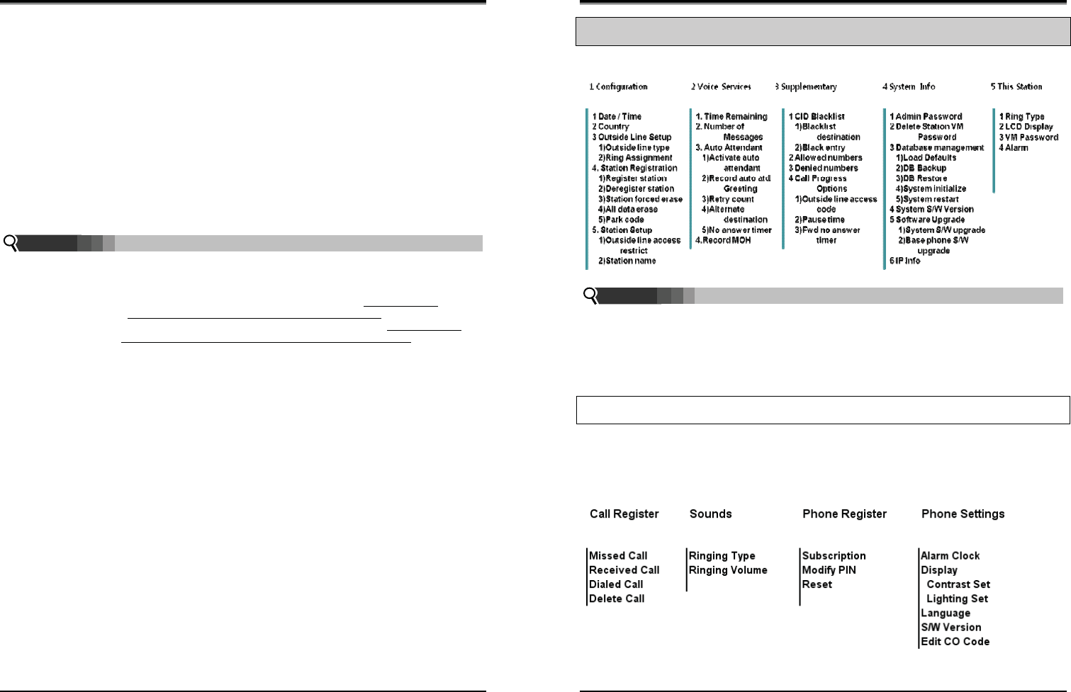
Wireless SOHO
Installation and Operation Manual
29
2.11.2 Terminating a Registration
To terminate a subscription, below procedure should be performed on the LWS-BS;
1. Press [Menu] button.
2. Press [Digit 1] (CONFIGURATION submenu), or Select [1. CONFIGURATION] using Navigation
up/down key and [OK] Button.
3. Press [Digit 4] (STATION REGISTRATION sub menu), or Select [4. STATION REGISTRATION]
using Navigation up/down key and [OK] Button.
4. Press [Digit 2] (DEREGISTER STATION submenu), or Select [2. DEREGISTER STATION] using
Navigation up/down key and [OK] Button.
5. Select the phone number using Navigation left/right key (S101~S107).
6. Press Navigation [OK] button or [OK] soft key.
7. When the subscription is complete below message is shown on LWS-BS LCD.
STATION : 10X
UNSUBSCRIBED : SUCCESS
¾ DEREGISTER : To erase registration information of both LWS-BS and Wireless terminals (LWS-
WK and GDC-400H/450H handsets).
¾ FORCED ERASE : To erase registration information of the relevant Wireless terminal. (e.g. in
case that the terminal is missing or non-functional)). In this case, the
registration information will be kept on the terminal itself.
¾ All Data ERASE : To erase registration information of all wireless terminals. In this case, the
registration information will be kept on the terminals themselves.
Procedure of erasing the registration information on the terminal itself:
1. Press [Menu] button.
2. Select [Phone Register] and press [OK] button.
3. Select [Reset] on the Menu and press [OK] button.
4. Enter HS PIN Code [default: 0000] using dial button. And then press [OK] button.
5. Select [Handset] on the menu and [OK] button.
Note:
Wireless SOHO
Installation and Operation Manual
30
2.12 Menu Trees
2.12.1 LWS-BS Menus
SYSTEM ADMIN PASSWORD: Should you set an ADMIN Password via Menu item 4, 1 on the LWS-BS
menu, it is advised that you record this password somewhere safe should you forget this password. A
service call is required if in fact you forget/lose this password.
For convenience you may record this password in the space provided below or on the last page of
this manual.
SYSTEM ADMIN PASSWORD
2.12.2 LWS-WK Menus
Note:
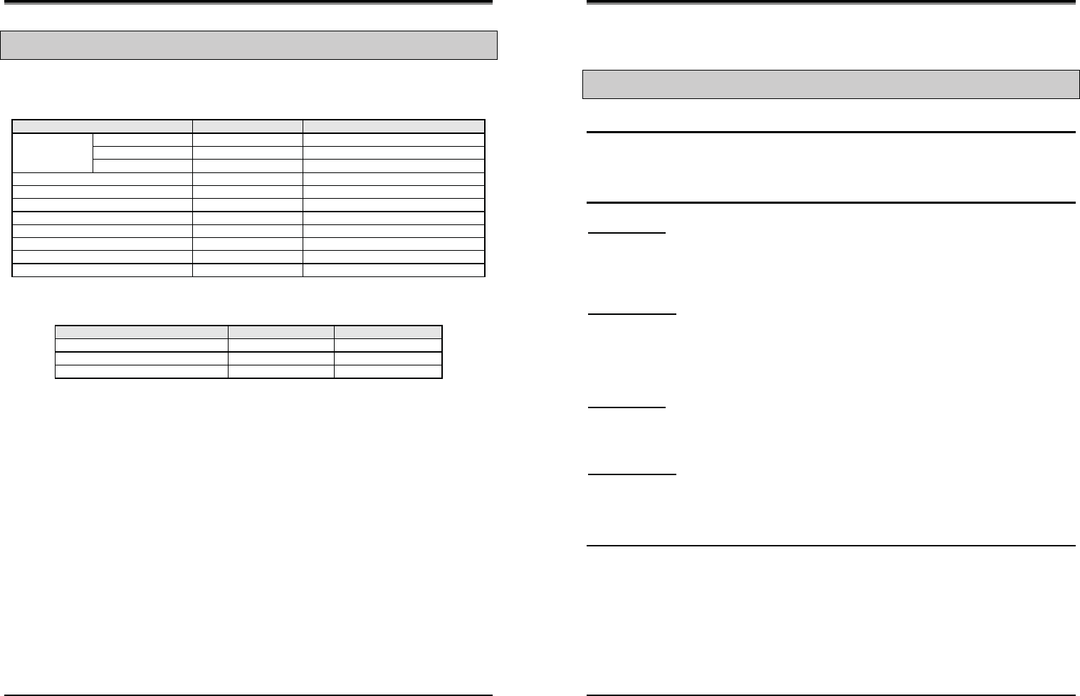
Wireless SOHO
Installation and Operation Manual
31
2.13 System Capacities
The LWS system is presently available in one configuration as shown in the Table 2.13.1.
Table 2.13.1 LWS System Capacity Chart
DESCRIPTION CAPACITY Remark
Stations LWS-BS station 1
Wireless Terminal 7 6 (Simultaneously)
FAX/SLT 1
Line 3
USB Host Port 1
System Speed Dial 800 (200-999) LWS-BS
Voice Mail Box 240 minutes Max. 3 Channel
Allow/deny list 50/50
Black call list 20
System Received /Dialed call log 15/15 LWS-BS
System Missed call log 900 pool LWS-BS
Table 2.13.2 Wireless Terminal Capacity
DESCRIPTION CAPACITY Remark
Phone book 60
Phone Dialed call log 10
Phone Received + missed call log 50
Wireless SOHO
Installation and Operation Manual
32
3
3
O
OP
PE
ER
RA
AT
TI
IO
ON
N
I
IN
NS
ST
TR
RU
UC
CT
TI
IO
ON
NS
S
3.1 Call Forward
Description
Users may have selected incoming calls re-routed to other stations or voice mail.
Forward feature is applied to internal calls, auto answering line calls, & normal line calls with ring assigned
only to one station.
Operation
To activate Call Forward:
LWS-BS station
1. Press the [Forward] soft button.
2. Select forward type.(“Uncondition”, “Busy”, “No Answer”, “Busy/No Ans”)
3. Select station number or VM.
4. Press [Save] soft button.
Wireless Terminal
1. Press [Talk] key in GDC-400H/450H or [Speaker] button in LWS-WK.
2. Dial {Call Forward} code (ex. 554).
3. Dial forward type (1:Unconditional, 2:Busy, 3:No Answer, 4:Busy/No Answer)
4. Dial station number or {VSF/VM access} code
To deactivate Call forward:
LWS-BS station
1. Press the [Forward] soft button in forward state.
2. Select “OFF” in forward type.
3. Press [Save] soft button.
Wireless Terminal
1. Press [Talk] key in GDC-4XX or [Speaker] button in LWS-WK.
2. Dial Call Forward code (ex. 554).
3. Dial ‘#’ to cancel Call Forward.
Conditions
1. A station receiving a forwarded call can transfer the call to the forwarding station.
2. Calls cannot be forwarded to a station in DND; if attempted, an error tone is returned.
3. Call Forward status is maintained in the system’s non-volatile memory for protection from power
outage.
4. Forward feature isn’t applied to SLT/Fax port.
5. A station can’t forward to DND station.
6. If a line isn’t auto an answering type and has 2 or more ring assigned stations, the call from the line
isn’t forwarded to the forwarded destination of ring assigned stations.
7. If the line has one ring assigned station, the call from the line can forward to forwarded destination
of the ring assigned station.
8. A station in DND can’t forward.
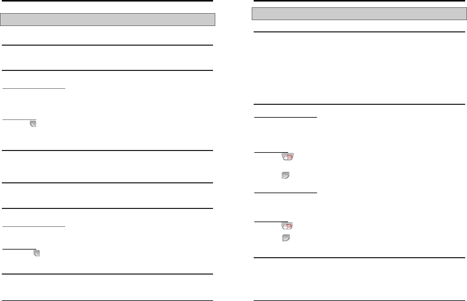
Wireless SOHO
Installation and Operation Manual
33
3.2 Call Pick-up
3.2.1 Directed Call Pick-Up
Description
A station may answer incoming and transferred intercom, line calls ringing at another station (Call Pick-Up).
All ringing calls are subject to Directed Call Pick-up except Queue Callbacks.
Operation
To Pick-up a call ringing at another station:
LWS-BS station and LWS-WK
1. Lift the handset or press [Speaker].
2. Dial {Directed Call Pick-up} code(ex.*7).
3. Dial the ringing station’s intercom number.
OR
GDC-400H/450H
1. Press ([Talk] key).
2. Dial {Directed Call Pick-up} code(ex.*7).
3. Dial the ringing station’s intercom number.
Conditions
1. Queue callback calls are not subject to Call Pick-up; any attempt will receive an error tone.
3.2.2 Group Call Pick-Up
Description
A station can answer (Call Pick-Up) incoming and transferred intercom, line calls ringing at another station.
All ringing calls, except Queue Callbacks, are subject to Pick-up by other stations.
Operation
To Pick-up a call ringing at another station:
LWS-BS station and LWS-WK
1. Lift the handset or press [Speaker].
2. Dial the Group Call Pick-up code (ex. **).
GDC-400H/450H
1. Press ([Talk] key).
2. Dial the Group Call Pick-up code (ex. **).
Conditions
1. Queue callback calls are not subject to Call Pick-up; any attempt will receive an error tone.
2. When several calls are ringing simultaneously, Call Pick-up will connect the first-in, highest priority
call. Call priority order is: Line transferred call > Line hold-recalled call > Line incoming call >
queued call.
Wireless SOHO
Installation and Operation Manual
34
3.3 Call Transfer
Description
Line calls can be transferred to other stations in the wireless SOHO system. Calls can be transferred
announcing the call (screened) or without an announcement (unscreened).
When a Line call is transferred, the Transfer Recall Timer (30sec) is initiated. If the timer expires before the
call is answered, the Hold Recall process is initiated.
Users can transfer an active Intercom call to other stations in the wireless system, using either screened or
unscreened transfer. When used, the Intercom station is placed on Exclusive Hold, and the Transfer Recall
timer is initiated,. if the timer expires before the Intercom call is answered, the call will bounce back (recall)
to the transferring station until answered or abandoned.
Operation
While on a call, to perform a Screened Call Transfer:
LWS-BS station and LWS-WK
1. Press [Trans].
2. Dial the station to receive the transfer.
3. When answered, announce the call.
4. Hang-up to complete the transfer.
GDC-400H/450H
1. Press ([Navigation right]) shorter than 1 second.
2. Dial the station to receive the transfer.
3. When answered, announce the call.
4. Press ([End] key]) to complete the transfer.
While on a call, to perform an Unscreened Call Transfer:
LWS-BS station and LWS-WK
1. Press [Trans].
2. Dial the station to receive the transfer.
3. Hang-up to complete the transfer.
GDC-400H/450H
1. Press ([Navigation right]) shorter than 1 second.
2. Dial the station to receive the transfer.
3. Press ([End] key]) to complete the transfer.
Conditions
1. The transferring station may camp a call at a busy station (refer to Camp-On).
2. A station in DND or out-of-service can’t receive a transfer; any attempt will result in an error tone.
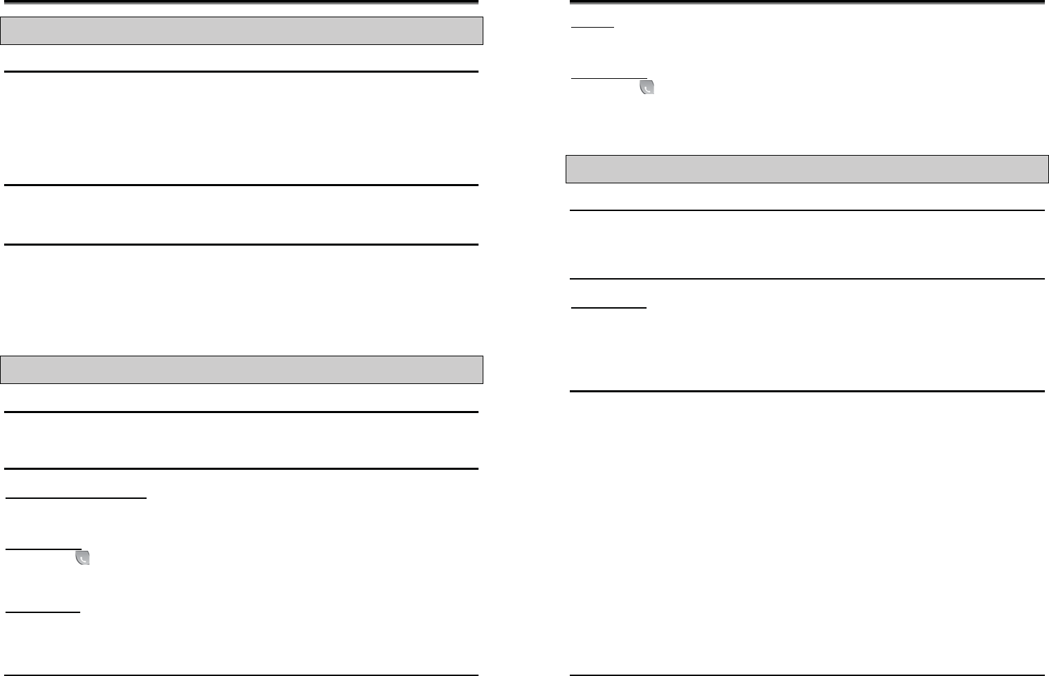
Wireless SOHO
Installation and Operation Manual
35
3.4 Call Waiting/Camp-On
Description
Call Waiting is used to notify a busy station that a call is waiting. The busy station is notified of the waiting
call with a Camp-On tone.
After receiving a busy signal, the calling station camps on to the called station. The called station can
respond by:
¾ answering the waiting call, which places the active call on hold,
¾ activating One-Time DND, or
¾ ignoring the Camp-On tone.
Operation
To activate a Camp-On while receiving the Intercom busy tone:
1. Press the ‘*’ button, called and calling stations receive Camp-On tone.
Conditions
1. The user may only Camp-On to a station in busy mode; a user may not Camp-On to a station in
DND, a conference, etc.
2. If the calling station disconnects from the call after activating Camp-On, Camp-On is cancelled.
3. A Camp-On tone is sent each time the calling user presses the ‘*’ button.
3.5 LINE Access
Description
Stations can access outgoing lines. The LWS-BS station and LWS-WK may use flexible buttons assigned
to access a specific line button for outgoing calls.
Operation
To place an outgoing Line call:
LWS-BS station and LWS-WK
1. Lift the handset or press the [Speaker] button.
2. Press desired {LINE} button, dial the {line access} code or {Individual Line Access} code.
GDC-400H/450H
1. Press ([Talk] key).
2. Dial the {Line access} code or {Individual Line Access} code.
To answer an incoming Line call:
LWS-BS station
1. Lift the handset or press the [Speaker] button. Or,
2. Press flashing {LINE} and lift the handset to speak privately.
Wireless SOHO
Installation and Operation Manual
36
LWS-WK
1. Lift the handset or press the [Speaker] button.
LWS-WK, does not support answering the incoming call by pressing {Line}/{Station} button in ringing state.
GDC-400H/450H
1. Press ([Talk] key).
3.6 Three-Party Voice Conference
Description
The system will allow three internal and external parties to be connected on a conference call. An
unlimited number of 3-party conferences may be established. Only the LWS-BS station may initiate a
conference call. If the base station hangs up, the conference will be terminated.
Operation
To establish an ad-hoc conference call:
LWS-BS station
1. Establish first call.
2. Press the [Conf] soft button; and the connected party is placed on exclusive hold.
3. Place second call.
4. When connected, press [Conf] soft button to establish 3-party conference.
Conditions
1. There is no limit on the number of 3-way conferences the system will support.
2. If the system receives a disconnect signal and no internal parties remain in the conference, the
conference is terminated and all parties are disconnected. If an internal party is still connected
when a disconnect signal is received, the connection to remaining parties is maintained.
3. A station that is busy, in DND or other non-idle state cannot be added to a conference.
Wireless SOHO
Installation and Operation Manual
37
3.7 Directory
Description
A name of up to 12 characters, may be assigned to each Station and System Speed Dial. When assigned,
a user of LWS-BS may place an external call to a Station or System Speed Dial using the name.
Operation
To use Dial by Name:
LWS-BS phone
1. Press the [Directory] soft button
2. Select “Station directory” or “System directory”.
3. Select desired name and press [Send] soft button
To toggle between the name and number display:
1. Press the [Select >] soft button
2. Press the [Name/Tel] soft button.
Conditions
1. The LCD will display multiple names (one per LCD line, up to 12 characters).
2. If a user selects a directory with no entries or there is no match to the user entry, error tone is
provided.
3.8 DND(Do Not Disturb)
Description
A station can be placed in DND to block incoming Line and Intercom calls and transfers.
Operation
To activate DND:
LWS-WK
1. Press the [DND] button; the [DND] button LED illuminates.
GDC-400H/450H
1. Press ([Talk] key).
2. Dial {DND} code (ex.553).
To remove DND:
LWS-WK
1. Press the [DND] button; the [DND] button LED extinguishes.
GDC-400H/450H
1. Press ([Talk] key) on DND state.
Wireless SOHO
Installation and Operation Manual
38
2. Dial {DND} code (ex.553).
Conditions
1. DND service is not available to the LWS-BS station.
2. Recalls for Line calls will override the DND feature.
3. A station in DND is bypassed by calls forwarded to the station; if the last station in a Call Forward
chain is in DND, the call will ring to the previous station in the chain.
4. When calling a station in DND, the station display will indicate the DND status.
5. The forwarding station can’t activate DND feature.
6. The station forwarded from the LWS-BS station can’t activate DND feature.
3.9 Headset Compatibility
Description
the LWS-BS station
The [Headset] button may be used only to select the mode between headset and speakerphone in idle state.
In busy/talk state, the switchover between headset and speakerphone isn’t supported.
In the headset mode, pressing the [Speaker] button will send audio to the Headset instead of the speakerphone.
LWS-WK
By pressing [Headset], the user can use the headset, immediately.
In talk mode with headset, if the user presses the [Speaker] button, the user can talk with the speakerphone.
Operation
LWS-BS station
To select Headset mode:
1. Press the [Headset] button.
2. The LED of [Headset] button is turned on.
To place/answer calls using the headset:
1. Press the [Speaker] with the phone in Headset mode.
LWS-WK
To place/answer calls using the headset:
1. Press the [Headset] button.
Wireless SOHO
Installation and Operation Manual
39
3.10 Hold
3.10.1 Hold
Description
Lines may be placed in a waiting state such that other stations on the system are able to access the Line. If
the call remains on hold at expiration of the System Hold Recall Timer, normal Hold Recall will be activated.
Operation
To place a call on System Hold:
LWS-BS station and LWS-WK
1. Press the [Hold] button.
GDC-400H/450H
1. Press ([Navigation right]) longer than 1 second.
To access a call from System Hold:
LWS-BS station and LWS-WK
1. Press the {LINE} button.
OR
1. Lift the handset or press the [Speaker] button.
2. Dial {Held Individual LINE Access} code (ex. 8#).
3. Dial the Line number (01-03)
OR
1. Lift the handset or press the [Speaker] button.
2. Dial {Held Line Access} code (ex. 8*).
GDC-400H/450H
1. Press ([Talk] key).
2. Dial {Held Individual LINE Access} code (ex. 8#).
3. Dial the Line number (01-03)
OR
1. Press ([Talk] key).
2. Dial {Held Line Access} code (ex. 8*).
Conditions
1. When a Line is placed on System Hold, the button LED will flash (it will flash at the holding station
and will flash at all other stations).
2. A call on System Hold can be retrieved from any station allowed access to the Line in the system
database using the Line button or the Held Line call access code.
Wireless SOHO
Installation and Operation Manual
40
3.10.2 Hold Recall
Description
When a user places a Line call on hold, a hold timer is activated. If the timer expires, the held call will recall
at the station for the I-Hold Recall time (30sec). If the call remains unanswered, the call is placed on
System Hold and the LWS-BS station also receives a recall for the Attendant Recall time (1min). If still
unanswered after the Attendant Recall time, the Line call is disconnected and the appropriate circuits are
returned to idle.
Operation
Hold Recall operation is automatic.
3.10.3 Automatic Hold
Description
While on an active Line call, the system will place the call on hold automatically if the user presses the
{Station/Line} button.
In this case, pressing a {Line} button while on a Line call will place the active call on hold and access the
selected Line.
Operation
To use Automatic Hold while on an active Line call:
LWS-BS station
1. Press the desired feature button or { Line } button; the active call is placed on Hold.
Conditions
1. There is no limit on the number of calls that can be placed on Hold using Automatic Hold.
3.11 CID Blacklist
Description
The system can employ caller number to determine the routing of incoming external calls.
The system will compare the received caller number to entries in the CID Blacklist, and if a match is found,
will route the call to the Voice mail of base station or disconnect the call.
Programming
CONFIGURATION Blacklist destination – [Menu] + 3 1 1
Blacklist entry — [Menu] + 3 1 2
Wireless SOHO
Installation and Operation Manual
41
3.12 Allowed/Denied Number
Description
Allow/Deny list has 50 codes and each code can contain up to 20 Digits.
This list is applied to the user with Outside Line access restrict (Menu + 1 5 1).
As digits are dialed, they are compared to entries using the following rules to allow or deny the call.
Rule 1 – If a table has no entries, no restrictions are applied.
Rule 2 – If there are only Deny entries, restrictions are provided as Deny only.
Rule 3 – If there are only Allow entries, restrictions are provided as Allow only.
Rule 4 – If there are both Allow and Deny entries, the Deny entries are searched. If the dialed number
matches a Deny entry, the call is restricted; if no match is found the call is allowed.
Programming
CONFIGURATION Outside Line Access Restrict – [Menu] + 1 5 1
Allowed Numbers – [Menu] + 3 2
Denied Numbers – [Menu] + 3 3
3.13 MOH (Music-On-Hold)
Description
When a call is placed on hold, the system will deliver a recorded message from VSF. In this way, the
connected user can determine that the connection is still active.
The base station records the VSF message for MOH. If a message isn’t recorded, the default MOH will be
delivered.
Operation
LWS-BS station
To record a VSF message for MOH:
1. Press the [Menu] button.
2. Dial 2 4.
3. Dial ‘#’.
4. After the record prompt and beep-tone, record message.
5. Press the [Save] button to stop recording and save the message.
Wireless SOHO
Installation and Operation Manual
42
3.14 Speed Dial
3.14.1 Display Security
Description
Individual and Common Speed Dial numbers may be programmed so that the digits are not displayed on
the LCD of the LWS-BS station.
Operation
1. To assign Display Security to a Speed Dial number:
2. Dial “*” as the first digit of the Speed Dial number.
Conditions
1. The number is displayed when programming a Speed Dial number.
2. Display Security is provided on all Line calls including calls that are transferred or recall.
3.14.2 Station Speed Dial
Description
The LWS-BS station can store commonly dialed numbers for easy access using Station Speed Dial bins.
The base station has access to 20 Speed Dial numbers.
Operation
To dial using an Station Speed Dial:
1. Lift handset or press the [Speaker] button.
2. Press the [Directory] button.
3. Press the [Speed] button.
4. Dial the desired bin number (00–19).
To program an Individual Speed Dial number:
1. Press the [Directory] button.
2. Press the [Speed] button.
3. Press the [Add] button.
4. Dial the Speed Dial bin number (00-19).
5. Press the { Line } button or dial the Line access code (ex. 9, 8801 ~ 8803).
6. Dial the number to be stored.
7. Press the [Save] soft button.
8. If desired, enter a name.
9. Press the [Save] soft button.
Conditions
1. Accessing an empty Speed Dial bin will return an error tone.
2. All Speed Dial numbers stored in memory are protected from power loss.
3. A name can be entered for a Speed Dial number to permit access from the Directory.
Wireless SOHO
Installation and Operation Manual
43
3.14.3 System Speed Dial
Description
Commonly dialed numbers can be stored by the LWS-BS station. Up to 800 System Speed Dial numbers
are available. Each Speed Dial number can be up to 23 characters in length and may include special
instruction codes.
Operation
To dial using a System Speed Dial:
1. Lift handset or press the [Speaker] button.
2. Press the [Directory] soft button.
3. Press the [Speed] soft button.
4. Dial the desired bin number (‘200’-‘999’).
To program a System Speed Dial number:
LWS-BS station
1. Press the [Directory] soft button.
2. Press the [Speed] soft button.
3. Press the [Add] soft button.
4. Dial the Speed Dial bin number (200-999).
5. Press the { Line } button or dial the Line access code(ex.9, 8801 ~ 8803).
6. Dial the number to be stored.
7. Press the [Save] soft button.
8. If desired, enter a name.
9. Press the [Save] soft button.
Conditions
1. Accessing an empty Speed Dial bin will return error tone.
2. All Speed Dial numbers are stored in memory protected from power loss.
3. A name can be entered for a Speed Dial number to permit access from the Directory.
4. If a Speed Dial number contains a “Dial-Tone Detect” command, Flash as the first entry in the bin,
and dial-tone detect is enabled for the Line, the system must detect dial-tone before dialing the
Speed Dial number.
Wireless SOHO
Installation and Operation Manual
44
3.15 VSF Integrated Auto Attendant/Voice Mail
3.15.1 VSF
Description
The Voice Store & Forward (VSF) unit, which is equipped in the wireless SOHO, provides the system
memory to support the integrated Auto Attendant, Voice Mail and system announcement applications
available in the System. The memory is employed to store Auto Attendant announcements, voice mail,
greetings and messages, and various system prompts.
The VSF has a storage capacity of up to 279 minutes of announcement and message storage.
3.15.2 Auto Attendant
Description
When a call comes into the system through a Line, the call may be routed to recorded VSF
Announcements.
If the user dials a station number, the Auto Attendant will complete an unsupervised call transfer to the
station.
Operation
To record an Auto Attendant Announcement:
LWS-BS station
1. Press the [Menu] button.
2. Dial 2 3 2.
3. Dial ‘#’.
4. After the record prompt and beep-tone, record message.
5. Press the [Save] soft button to stop recording and save the message.
To delete a recording:
1. Press the [Menu] button.
2. Dial 2 3 2.
3. Press [Delete] soft button.
Conditions
1. If the external caller dials a station number and the station is busy or there is no answer, the call
is routed by busy/error/no answer (Exception) destination (menu 2 3 4).
2. No answer routing time is set by the No answer Timer (Menu + 2 3 5).
3. The greeting is played by retry count (menu + 2 3 3).
4. The auto attendant feature isn’t applied to Tel/Fax Line(Menu 1 3 1). In Tel/Fax” Line, after fax
tone detection time, the call goes to ring assigned stations.
Wireless SOHO
Installation and Operation Manual
45
3.15.3 VSF Voice Mail
3.15.3.1 Message Storage
Description
When a station activates Call Forward to the VSF Group, a call is transferred to a VSF mail box.
The caller connects to the called station’s User Greeting followed by a beep tone.
The remote caller can record a message and hang-up or dial ‘*’ for further options. When disconnection
occurs, the VM application stores the message in the called user’s voice mail-box and activates the
Message Waiting indication at the user’s station.
Operation
Remote Caller
To leave a voice message after hearing announcement:
1. Wait for the beep, then leave a message.
2. Hang up to quit recording,
OR
2. Dial ‘*’ for more options.
Conditions
1. If all the VSF channels are in use, the Ring Back tone is provided until a VSF channel is available.
2. Individual User Greetings and Voice Mails are protected from AC power loss.
3.15.3.2 Message Retrieval
Description
A user can access their Mail Box locally by placing a call to the VSF Voice Mail group, by pressing the
[MSG] button, or by dialing VSF voice mail code(ex. 620)
Prompts are then received to guide the user in the Voice Mail Box operation. The user must enter a Mail
Box number, generally the station number, and a corresponding password in response to the «Request for
Password» («Please enter your password code.») prompts.
If the user enters a valid and matching Mail box and password, the «Number of Messages» prompt (“You
have xx new messages, You have yy saved messages.”) is received. At this point, the user also receives
the “VM long option prompt” (“To play new messages, press one, to play saved messages, press two, to
set greeting or password, press eight, to disconnect, press pound, Press 0 for the operator, Press nine to
hear this message again.”).
When the user responds by dialing 1, the first new message is played. At the end of message playback,
the «New Message option» prompt is played (“To replay message, press one, to listen to the next message,
press two, to delete message, press three, to forward message, press four, to call the sender, press five, to
skip message, press six, to return to main menu, press nine.”). This process is repeated until the last new
message is played and the «No Message» prompt (“No Messages») is played.
When the user dials 2 in response to the «Number of Messages» prompt, the first-saved message is played.
At the end of the message, the «Saved Message option» prompt is played (“To replay message, press one,
Wireless SOHO
Installation and Operation Manual
46
to listen to the next message, press two, to delete message, press three, to forward message, press four,
to call the sender, press five, to return to main menu, press nine.”). This process is repeated until the last
new message is played and the «No Message» prompt (“No Messages») is played.
In addition to the options indicated in the prompt, a user can record a memo, which is attached to the
current voice mail by dialing the digit 7. The current voice mail and memo can then be forwarded to other
Office Box users.
When the user dials 9 in response to the «Number of Messages» prompt or during or at the end of a
message the «VM long Options» prompt is played.
Operation
LWS-BS station
1. Press [Menu] button.
2. Press 5 3.
3. If a current password exists, enter the station number and current password.
4. And press [Save] soft button.
5. Enter the station number and new password
6. Press [Navigation down] button.
7. Enter the station number and new password.
8. Press [Save] soft button.
LWS-WK
1. Press [Speaker] button.
2. Press {Change VM password} code (ex.559).
3. If a current password exists, enter the station number and current password.
4. And press [Hold] button.
5. Enter the station number and new password
6. Press [Hold] button in LWS-WK.
GDC-400H/450H
1. Press ([Talk] key).
2. Press {Change VM password} code (ex.559).
3. If a current password exists, enter the station number and current password.
4. Press ([Navigation right]) longer than 1 second.
5. Enter the station number and new password.
6. Press ([Navigation right]) longer than 1 second.
To remove password for voice mail forcedly:
1. Press [Menu] button in LWS-BS station.
2. Press 4 2.
3. Select the station number with [Navigation right/left] button.
4. Press [OK] soft button.
To retrieve Voice Mail locally:
LWS-BS station
1. Lift the handset or press the [Speaker] button.
Wireless SOHO
Installation and Operation Manual
47
2. Dial {Voice mail} code(ex. 620).
3. Dial the Mail Box and corresponding password to receive the “Number of Messages” prompt.
4. Dial desired option code.
5. At completion of session, hang-up to return to idle.
LWS-WK
1. Lift the handset or press the [Speak] button.
2. Dial {Voice mail} code(ex. 620).
3. Dial the Mail Box password to receive the “Number of Messages” prompt.
4. Dial desired option code.
5. At completion of session, hang-up to return to idle.
GDC-400H/450H
1. Press ([Talk] key).
2. Dial Voice mail code(ex. 620).
3. Dial the Mail Box password to receive the “Number of Messages” prompt.
4. Dial desired option code.
5. At completion of session, Press ([End] key) to return to idle.
Conditions
1. Messages are retrieved in LIFO (Last in First out) order.
2. The default password for voice mail is ‘*’.
3. If the user removes his password for voice mail, the user can’t enter his voice mail box.
4. If the user has lost his password for voice mail, first force remove password at LWS-BS station
and change password at his phone.(refer to operation)
3.15.3.3 Message Retrieval Options
Description
The user may dial the digit 9 to receive the “VM Long Options” prompt while in the Voice Mail Box,
including during or after a voice message or system prompt, except when an option has been selected that
requires user dialing. Some options involving user dialing include the Message Retrieval Option 1/2 (Play
New/Saved Message), 7 (Cancel or Forward message, Remote Access Only) or 8 (Mail Box settings),
refer to Table. The “VM long Options” prompt is:
«To play new messages, press one, to play saved messages, press two, to set station forwarding, press
seven (This option is available only for remote access), to set greeting or password, press eight, to
disconnect, press pound, Press 0 for the operator, Press nine to hear this message again.»
The VSF Voice Mail will respond to incoming digits as shown in the following table.
Digit Function
1 Play New MSG
2 Play Saved MSG
7 Set Cancel/Fwd, available only for remote access
8 Mail Box Setting, «Mailbox Settings» prompt
9 VM Long options
# Drop, «Goodbye”
0 Attd Call, Call to Attendant.
Wireless SOHO
Installation and Operation Manual
48
Operation
To access a Message Retrieval option
At any time after the “Number of Messages” prompt, dial a Message Retrieval Option digit. The system
initiates the selection providing any needed prompts.
Conditions
1. If the user remains off-hook after a call placed through the voice mail is complete, the user will be
returned to the previous place in the Voice Mail Box. If the user hangs up, the VSF will recall at
the user Station, and upon answer will play “Request Mail Box Number” prompt.
3.15.3.4 Voice Mailbox Settings
Description
The user can program the Mail Box settings for their mailbox including a security password and a greeting.
When a user presses «8» while retrieving messages, the «Mailbox Setting» prompt, (“To edit your greeting,
press one, to edit you password, press two. To return to main menu, press nine”).
Operation
To program Mail Box settings while “in” the Voice Mail Box:
Press ‘8’, for Mail Box settings; the “Mail Box Setting” prompt is received.
To enter a new password:
1. Dial ‘7’ to receive the “Password Entry” prompt (“Please enter your new password and press
pound when finished.»).
2. Dial new password.
3. Press ‘#’; the “Reenter Password” prompt will be heard («Please re-enter your password to
confirm and press pound when finished.»).
4. Dial new password again.
5. Press ‘#’ and the “Password Confirmation” prompt will be heard («Your password is saved.»).
To create a new greeting:
1. Dial ‘4’ to hear the “Greeting Option” prompt («To listen to your current greeting, press five to
record a new greeting, press seven, to return to the main menu, press nine.”).
2. Dial ‘5’, to hear your greeting.
OR
3. Dial ‘7’ to hear the “Record Greeting” prompt («At the tone, record your new greeting, press #
when done.»).
4. After the beep, record your desired greeting speaking in a normal voice.
5. Press ‘#’ and receive the “Greeting Confirmation” prompt («Your greeting is saved.»).
To adjust Mail Box Settings:
1. Dial ‘9’ to hear the “Mail Box Setting prompt” (“To edit your greeting, press one, to edit you
password, press two, to return to main menu, press nine”).
Conditions
1. If the dialed number is not recognized, the «Invalid Entry» prompt is played.
Wireless SOHO
Installation and Operation Manual
49
2. The user must assign a password (Authentication code, up to 12 digits) before access to the
mailbox will be allowed.
3.15.3.5 Call Forward from VM
Description
External users can activate or deactivate Call Forward for their station. Pressing ‘7’ while retrieving
messages will return the «Mailbox Set Forward» prompt, (“To forward calls to another extension, press one.
to cancel forwarding, press 2 to return to the main menu, press nine.”).
Operation
1. To activate Call Forward while in the VM:
2. Press ‘7’, for Mail Box set forward, the “Mail Box Set Forward” prompt is received.
To activate Call Forward:
1. Dial ‘1’ and receive the “Password Entry” prompt (“Please enter the number to forward to …»).
2. Dial the Station Number as follows:
z To forward to another station, dial the station number.
To deactivate Call Forward:
1. Dial ‘2’ and receive the “Station forwarding is canceled” prompt.
To return to the Main menu:
1. Dial ‘9’ and receive the “Mail Box Settings” prompt.
Conditions
1. If the user is external, the user must begin dialing within and dial subsequent digits within the
VSF Inter-Digit Timer; if not, the call is released.
2. This Mail Box Set Forward is only available for external users.
3.16 Wake-Up Alarm
Description
This feature allows a user to set a wake-up time or desired time to be alerted. When the time is reached,
the system will signal with an audible and visual signal.
Operation
To register Wake-Up:
LWS-BS station
1. Press the [Menu] button.
2. Dial 5 4.
3. Select “Single” or “Continuous”
Wireless SOHO
Installation and Operation Manual
50
4. Dial 2-digit hour and 2-digit minute for alerting.
5. Press [Save] button.
To erase Wake-Up:
LWS-BS station
1. Press the [Menu] button.
2. Dial 5 4.
3. Select “OFF”.
4. Press [Save] button.
Conditions
1. The Wake-up alarm Ring signal is 30 seconds, On/90 seconds, Off (3 times). If no action is
taken by the user, the ring signal is given to the Attendant with a display designating the station
number that did not respond.
2. Time (hh:mm) must be entered in the Military 24-hour format.
3. The daily alarm will reset and repeat each day until erased (cancelled)’ the One-time alarm will
reset and cancel automatically.
3.17 Intercom Call (ICM Call)
Description
A non-blocking ICM is available to all stations in the system. Users may place an intercom call to other
stations in the system by dialing applicable digits as defined in the system Numbering Plan.
Operation
To place an intercom call:
LWS-BS station and LWS-WK
1. Lift the handset or press the [Speaker] button to receive ICM dial tone.
2. Dial station number or press the {Station} button.
3. For ring-back tone, await answer.
GDC-400H/450H
1. Press ([Talk] key) to receive ICM dial tone.
2. Dial station number.
3. For ring-back tone, await answer.
Conditions
1. Intercom Dial tone will time-out if action is not taken within Dial-Tone Time or, if the time between
digits exceeds the Inter-digit Timer; error tone is received on dial tone time-out.
2. ICM Dial tone is halted after dialing the first digit.
3. If the called station is busy, Intercom Busy tone is provided for the Busy Tone time (7 sec.) then,
Error tone is sent by the system; the caller may disconnect or activate a feature such as Message
Wait/Callback.
Wireless SOHO
Installation and Operation Manual
51
3.18 Intercom Call Hold
Description
While on an active ICM Call, Users can place the ICM Call on hold; the held station will receive the
assigned MOH. The call is placed on Exclusive Hold and recalls at the holding station after the station
returns to idle.
Operation
To place an active ICM call on hold:
LWS-BS station and LWS-WK
1. Press the [Hold] button.
GDC-400H/450H
1. Press ([Navigation right]) longer than 1 second;
To retrieve the held ICM call:
LWS-BS station and LWS-WK
1. Press the {Station} button associated with the held station.
GDC-400H/450H
1. Dial a station number of held station;
Conditions
1. Only one ICM call may be placed on hold at a time.
3.19 Line Ring Assignment
Description
Each station in the system can be programmed to provide an audible signal when the system detects an
incoming call on specified Lines.
Operation
To set “Line ring assignment”:
LWS-BS station
1. Press [Menu] button.
2. Dial 1 3 2.
3. Select a Line.
4. Press the button of desired station and LED of button is turned on.
5. Press [Save] button.
Conditions
1. A busy station receives the Muted ring or Call Waiting tones (as appropriate) for the station’s off-
hook ring assignment. In Night/weekend mode, Line ring assignment is disabled.
2. In case of DECT type station, maximum 6 DECT type station can be assigned each line.
Wireless SOHO
Installation and Operation Manual
52
3.20 Night/Weekend mode
Description
In night/weekend mode, a specific station is assigned as ring destination of all call from Line.
Operation
LWS-BS station
To activate night/weekend mode:
1. Press [DND] button.
2. Select the ring destination.
3. Press [Save] soft button. Then DND LED is turned on.
To deactivate night/weekend mode:
1. Press [DND] button in night/weekend mode.
2. Select “OFF”.
3. Press [Save] soft button. Then DND LED is turned off.
Conditions
1. In night/weekend mode, the DND LED of base station is turned on.
2. If the LWS-BS station is in forwarding to other station, the user can activate/deactivate the
night/weekend mode in the forwarded station.
3.21 Call Log Display
Description
The LWS-BS station can view a log of incoming, outgoing and missed calls on the display and place a call
with call log.
Operation
LWS-BS station
To place a call with Call Log:
1. Press the [Call log] soft button.
2. Select “received” or “dialed” or “missed”.
3. Select the desired number and press [Send] soft button.
To delete Call Log:
1. Press the [Call log] soft button.
2. Dial 4.
3. Select the option and press [OK] soft button.
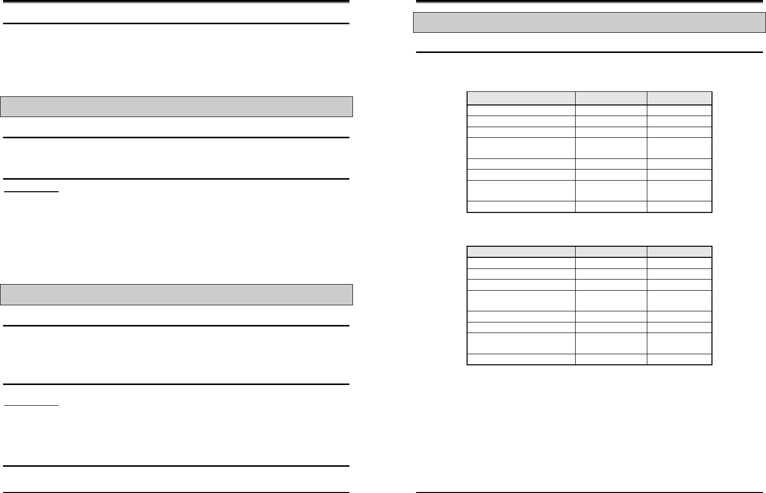
Wireless SOHO
Installation and Operation Manual
53
Conditions
1. Maximum count of Received and Dialed call log is 15 each.
2. Missed call has 900 pools. So, 900 missed call can be saved. If the pool is full of the 900 missed
call log, the new missed call log can’t be saved.
3. Missed call can be saved to speed dial, but received/dialed call can’t be saved to speed dial.
3.22 Mute
Description
The user can turn off audio transmission from the handset, speakerphone or headset microphone (Mic
Mute).
Operation
LWS-BS station
To Mute the Microphone:
1. Press the [Mute] button; the [Mute] button LED illuminates, the microphone (Handset,
Speakerphone, Headset) is muted, and the connected party receives silence.
To activate the microphone:
1. Press the illuminated [Mute] button; the [Mute] button LED extinguishes, and the microphone is
activated, transmitting audio to the connected party.
3.23 Tel/Fax Line
Description
If Tel/Fax Line Mode (Menu 1 3 1) is selected, the system will detect a FAX tone within the fax tone
detection time. After detecting FAX tone, the system sends the call to the SLT/FAX port to respond to it. If
a FAX tone is not detected within the fax tone detection time, the system will transfer the call to the ring
assigned stations for that particular Tel/Fax line.
Operation
To set Tel/fax line:
LWS-BS station
1. Press the [Menu] button.
2. Dial 1 3 1.
3. Select “Tel/Fax” with [Navigation right/left] button.
4. Press [Save] soft button.
Conditions
1. The fax tone detection time is 10 seconds.
2. The auto attendant feature isn’t applied to Tel/Fax Line.
Wireless SOHO
Installation and Operation Manual
54
3.24 Feature Code for LWS-BS
Description
User can access Feature Code unlocking several functions.
z NZ
Feature Code Remark
Intercom Call 700-708
Group Call Pickup *1
Direct Call Pickup *42
Individual Line Access 48 XX XX : 01 ~ 03
(line number)
Line Access Code 1
VSF/VM access code 620
Access individual held line 4# XX XX : 01 ~ 03
(line number)
Access held line 4*
z Other countries
Feature Code Remark
Intercom Call 100-108
Group Call Pickup **
Direct Call Pickup *7
Individual Line Access 88 XX XX : 01 ~ 03
(line number)
Line Access Code 0
VSF/VM access code 620
Access individual held line 8# XX XX : 01 ~ 03
(line number)
Access held line 8*
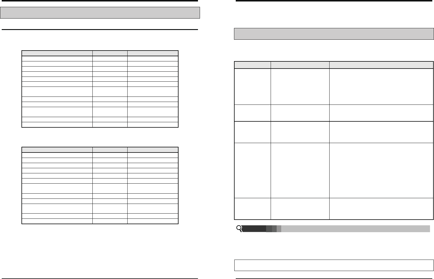
Wireless SOHO
Installation and Operation Manual
55
3.25 Feature Code for LWS-WK
Description
User can access Feature Code unlocking several functions.
z NZ
Feature code Remark
Intercom Call 700-708
DND 553
Call Forward 554
Change VM password 559
Group Call Pickup *1
Direct Call Pickup *42
Individual Line Access 48 XX XX : 01 ~ 03
(Line number)
Line Access Code 1
VSF/VM access code 620
Access individual held Line 4# XX XX : 01 ~ 03
(Line number)
Access held Line 4*
Attendant code 0
z Other countries
Feature code Remark
Intercom Call 100-108
DND 553
Call Forward 554
Change VM password 559
Group Call Pickup **
Direct Call Pickup *7
Individual Line Access 88 XX XX : 01 ~ 03
(Line number)
Line Access Code 0
VSF/VM access code 620
Access individual held Line 8# XX XX : 01 ~ 03
(Line number)
Access held Line 8*
Attendant code 9
Wireless SOHO
Installation and Operation Manual
56
4
4
U
US
SE
EF
FU
UL
L
I
IN
NF
FO
OR
RM
MA
AT
TI
IO
ON
N
4.1 Trouble shooting
If you experience any problems with the normal use of your phone, you should first power-off and
disconnect the battery. Then connect it again, and connect the power again. If the phone continues to have
problems, please check the following Table before contacting the Customer Service center.
PROBLEM POSSIBLE CAUSE SOLUTION
There is no dial
tone
• Is the telephone line cord
correctly plugged into the
base and telephone
socket?
• Is the Terminal registered
to the base?
• Check that the base is connected to the main power
source and the battery is properly installed.
• If you try to make a call and the terminal is not
registered, the display shows ‘Out of Range’.
Cannot make or
receive calls
• Are the Handset batteries
charged?
• If the battery symbol shows empty then replace the
handset on the charger and let it charge for a few
hours.
Terminal does
not ring
• Have you set the terminal
ringer volume to Volume
Off?
• You can set the ringer volume for LWS-BS,
Wireless Keyset and Handset. Verify if the ringer
volume is set too low for you, and adjust if
necessary.
Cannot link up
with the LWS-BS
station
• Is “Range Out” display? • The LWS-BS power cable may not be connected.
The AC power has failed and/or the batteries in the
base could be low or flat; recharge or replace the
batteries.
• Verify the antenna of the LWS-BS is attached
tightly. Otherwise put it into the LWS-BS and turn it
clockwise.
• Verify you are in range of the LWS-BS; move closer
to the base if necessary.
System Power
failure
• Is the power connected
well?
• Check all connections
• If there is an AC power failure, you must re-connect
the AC adapter to turn-on the system again.
SYSTEM ADMIN PASSWORD: Should you set an ADMIN Password via Menu item 4, 1 on the LWS-BS
menu, it is advised that you record this password somewhere safe should you forget this password. A
service call is required if in fact you forget/lose this password.
For convenience you may record this password in the space provided below.
SYSTEM ADMIN PASSWORD
Note:
NOTICE
This equipment has been tested and found to comply with the limits for a Class A digital device,
pursuant to Part 15 of the FCC Rules. These limits are designed to provide reasonable protection
against harmful interference in a residential installation. This equipment generates uses and can
radiate radio frequency energy and, if not installed and used in accordance with the instructions, may
cause harmful interference to radio communications. However, there is no guarantee that interference
will not occur in a particular installation. If this equipment does cause harmful interference to radio or
television reception, which can be determined by turning the equipment off and on, the user is
encouraged to try to correct the interference by one or more of the following measures:
• Reorient or relocate the receiving antenna.
• Increase the separation between the equipment and receiver.
• Connect the equipment into an outlet on a circuit different from that to which the receiver is needed.
• Consult the dealer or an experienced radio TV technician for help.
This device complies with part 15 of the FCC Rules. Operation is subject to the following two
conditions:
(1) This device may not cause harmful interference; and (2) This device must accept any interference
received, including interference that may cause undesired operation.
CAUTION : Any changes or modifications in construction of this device which are not expressly
approved by the party responsible for compliance could void the user’s authority to operate the
equipment.
RF Exposure Statement:
This equipment complies with FCC RF radiation exposure limits set forth for an uncontrolled
environment. Use of other accessories may not ensure compliance with FCC RF exposure guidelines.
This device must not be co-located or operating in conjunction with any other antenna or transmitter.
The changes or modifications not expressly approved by the party responsible for compliance could
void the user’s authority to operate the equipment.
GDC-450H :
The tests are performed in positions and locations (e.g., at the ear and worn on the body) as required
by the FCC for each model. The SAR value for this model handset when tested for use at the ear is
0.051 W/kg and when worn on the body, as described in this user guide, is 0.065 W/kg.
LWK-WK & LWS-BS :
In order to comply with FCC RF exposure requirements the base station must be installed with a
minimum separation distance of 20 cm from the antennas to the user or near by persons.
Installation and Operation Manual
2.10.1 Country code
To set the nation code, perform the following:
1. Press the [Menu] button on the LWS-BS.
2. Select 1. CONFIGURATION > 2. COUNTRY.
3. If you want to change country, press [CHANGE] soft key or [OK] Navigation key.
4. Set the Country code (61 for Australia ).
5. When finished, press the [SAVE] button, and system will ask you to confirm it.
6. If you select [YES] as pressing digit 1, system will restart and database will be initialized.
Note:
It is recommended that the Country code is configured to enable proper operation of the LWS-BS
according to the specific country.
2.10.2 LWS-BS Date and Time
The Base Date and Time can be set and adjusted by the User.. In the event of a power failure, the system
will retain Date and Time including Database with internal Lithium Battery. All wireless keysets registered
to the Base Station will automatically adjust Date and Time according to the Base Station value after
pressing Talk key or Speaker button.
To set the Date & Time:
1. With the LWS-BS in idle state, press the [Menu] button.
2. Select 1. CONFIGURATION > 1. DATE / TIME.
3. In this menu, set the Date and Time by entering the desired values using the keypad and scrolling
with the navigation arrow keys.
4. When finished, press the [SAVE] soft key or press the [OK] button Navigation key and a
confirmation tone will be heard.
Note:
Date and Time of Wireless Keysets (LWS-WK) and Wireless Handsets (GDC-400H and GDC-
450H), are automatically updated by the LWS-BS after pressing Talk key or Speaker button
so there is no need to set the date and time on these.
2.11 Terminal Registration and Termination
The LWS-BS controls the functional service and registration related to the LWS-WK and GDC-400H/450H
including a registration function. Each LWS-WK and GDC-400H/450H must be registered to the LWS-BS (Base
Station) before use.
24