-
Contents
-
Table of Contents
-
Troubleshooting
-
Bookmarks
Quick Links
Installation and Service
Instructions
AUTOMATIC
11.15am 71°F
180
Boiler Controls
Logamatic 2107
For the installing contractor
Please read carefully prior
to commissioning or
servicing.
Related Manuals for Buderus Logamatic 2107
Summary of Contents for Buderus Logamatic 2107
-
Page 1
Installation and Service Instructions AUTOMATIC 11.15am 71°F Boiler Controls For the installing contractor Logamatic 2107 Please read carefully prior to commissioning or servicing. -
Page 2
Change to SETBACK if no room sensor is being used or RMSETBACK if a room sensor is present Refer to page 10 for additional details. Logamatic 2107 controls — We reserve the right to make any changes due to technical modifications. -
Page 3: Table Of Contents
….. . . 46 Logamatic 2107 controls — We reserve the right to make any changes due to technical modifications.
-
Page 4
……….. . 68 Logamatic 2107 controls — We reserve the right to make any changes due to technical modifications. -
Page 5: Safety Instructions And User Notes
USER NOTE User notes help you use and handle this technology in the optimum, most economical, safe and environmentally- friendly manner. Logamatic 2107 controls — We reserve the right to make any changes due to technical modifications.
-
Page 6: Please Observe These Safety Instructions
RISK TO LIFE z In an emergency, switch OFF the emergency shutoff switch outside the WARNING! boiler room. Logamatic 2107 controls — We reserve the right to make any changes due to technical modifications.
-
Page 7: Setting Parameters And Display Data For The Logamatic 2107
MAX TEMP Maximum heating circuit temperature REMOTE 2 Remote control ON/OFF DIFF T Room temperature hook-up OA SETBACK Type of setback OFFSET Room temperature offset Logamatic 2107 controls — We reserve the right to make any changes due to technical modifications.
-
Page 8
6 Only if FM 241 module is installed and if heating circuit 2 is selected as an «UND-FLOOR» or «RADIATOR» heating system. 7 Only if FM 244 module is installed. Logamatic 2107 controls — We reserve the right to make any changes due to technical modifications. -
Page 9: Installation
G234: The tridicator assembly should be moved to the supply piping and replaced with the chrome plated Logamatic well. The sensor bundle must be inserted into this well. Logamatic 2107 controls — We reserve the right to make any changes due to technical modifications.
-
Page 10
Tilt the display to the desired position. z Replace the top housing of the controls and fasten the two screws. The control is ready to be placed into operation. Logamatic 2107 controls — We reserve the right to make any changes due to technical modifications. -
Page 11: Installation Of The Logabracket
GA124, GA244 These boilers do not require the bracket as strain relief connections are provided on the rear of the boiler. Logamatic 2107 controls — We reserve the right to make any changes due to technical modifications.
-
Page 12: Logamatic 2107 Controls
Item 5: ON/OFF switch Item 6: Keys for basic functions Item 7: Dial Item 8: Keys for extended functions Item 9: Display Item 10: Flap Logamatic 2107 controls — We reserve the right to make any changes due to technical modifications.
-
Page 13
Item 1: Automatic mode following a program Item 2: Normal heating mode (day mode) Item 3: Flue gas test (for measuring flue gases) Item 4: Setback heating mode (night mode) Logamatic 2107 controls — We reserve the right to make any changes due to technical modifications. -
Page 14
Item 11: «Display» key – Select the standard display This keypad is used, for example, to enter the day, set the time, select temperature values, etc. Logamatic 2107 controls — We reserve the right to make any changes due to technical modifications. -
Page 15: Checking The Manual Reset High Limit (Stb)
Release the «Display» key. °F z Remove the dial on the boiler water thermostat (Fig. 4). Fig. 4 Remove the dial on the boiler aquastat. Logamatic 2107 controls — We reserve the right to make any changes due to technical modifications.
-
Page 16
(Fig. 6). 1…7 Zeit Temp PROG Urlaub Auswahl So/Wi Anzeige Install Zurück Fig. 6 Remove the STB cover. Item 1: STB cover. Logamatic 2107 controls — We reserve the right to make any changes due to technical modifications. -
Page 17: Using The Service Level
The service level is now activated. USER NOTE The unit automatically returns to the standard display if no settings are made within 5 minutes. Logamatic 2107 controls — We reserve the right to make any changes due to technical modifications.
-
Page 18: Calling Up The Menu
REMOTE Press the «ENTER» key to return to the higher-level menu. CIRCUIT 1 PERIM HTG Press the «AUT» key to exit the service level. Logamatic 2107 controls — We reserve the right to make any changes due to technical modifications.
-
Page 19: Modifying Settings
Return to the standard display Press «ENTER». The unit automatically returns to the standard display if no key is pressed within 5 minutes. Logamatic 2107 controls — We reserve the right to make any changes due to technical modifications.
-
Page 20: General Data
5 second pause, then the mixing valves are set to «OPEN» for 3 minutes. All pumps then return to normal operation. Logamatic 2107 controls — We reserve the right to make any changes due to technical modifications.
-
Page 21: System Frost Protection
The setting applies to all heating circuits. Input range Factory setting System frost protection -4°F – 50°F (-20°C – 10°C) 41°F (5°C) Logamatic 2107 controls — We reserve the right to make any changes due to technical modifications.
-
Page 22: Type Of Building
Note: In areas where rapid changes in outdoor temperature occur, choose Building Response 1. Logamatic 2107 controls — We reserve the right to make any changes due to technical modifications.
-
Page 23
Release «Display» to store your input. Press «ENTER» to return to the next higher level. Input range Factory setting 1 (low) Building response 2 (medium) 3 (high) Logamatic 2107 controls — We reserve the right to make any changes due to technical modifications. -
Page 24: Setting The Burner Type
Press «ENTER» to return to the next higher level. Input range Factory setting Burner system without burner module FM 242 – 1-stage Burner system with burner module FM 242 1-stage/2-stage/modulating 2-stage Logamatic 2107 controls — We reserve the right to make any changes due to technical modifications.
-
Page 25: Minimum Modulating Output Of The Modulating Burner
Release «Display» to store your input. Press «ENTER» to return to the next higher level. Input range Factory setting 10 %–60 % 30 % minimum modulation output Logamatic 2107 controls — We reserve the right to make any changes due to technical modifications.
-
Page 26: Operating Time Of The Modulating Burner Actuator
Press «ENTER» to return to the next higher level. Input range Factory setting Operating time of the actuator 5 – 60 seconds 12 seconds Logamatic 2107 controls — We reserve the right to make any changes due to technical modifications.
-
Page 27: Pump Logic
Press «ENTER» to return to the next higher level. Input range Factory setting Pump logic for 104°F (40°C) 1-stage 60°F – 140°F 113°F (45°C) 2-stage (15°C – 60°C) 122°F (50°C) Modulating burners Logamatic 2107 controls — We reserve the right to make any changes due to technical modifications.
-
Page 28: Maximum Boiler Temperature
Input range Factory setting 158°F – 210°F Maximum OFF temperature 176°F (80°C) (70°C – 99°C) Logamatic 2107 controls — We reserve the right to make any changes due to technical modifications.
-
Page 29: Language Selection
«AMERICAN». Now hold down the «Display» key and turn the dial to set the language. Release the «Display» key to store the set language. Logamatic 2107 controls — We reserve the right to make any changes due to technical modifications.
-
Page 30: Heating Circuit Data
If the right heating system is selected, the other heating circuit parameters are preset. They must still be verified, however. Further information on this can be found on the next page. Logamatic 2107 controls — We reserve the right to make any changes due to technical modifications.
-
Page 31
If there is only one heating circuit with mixing valve present (HK2), circuit 1 must be set to «NO SYSTEM». If the «NO SYSTEM» setting is used, all of the following settings are hidden for this circuit. Logamatic 2107 controls — We reserve the right to make any changes due to technical modifications. -
Page 32
FLOOR HTG Input range Factory setting NO SYSTEM PERIM HTG Heating circuit 1 PERIM HTG NO SYSTEM Heating circuit 2 FLOOR HTG FLOOR HTG Logamatic 2107 controls — We reserve the right to make any changes due to technical modifications. -
Page 33: Reference Design Temperature
(+20) (+15) (+10) (+5) (±0) (-5) (-10) (-15) The factory setting is: Outdoor temperature [°F(°C)] With PERIM HTG: 167°F (75°C) Fig. 9 Determining the heating With FLOOR HTG: 113°F (45°C) curve Logamatic 2107 controls — We reserve the right to make any changes due to technical modifications.
-
Page 34
Reference design temperature for PERIM HTG 86 – 194°F (30 – 90°C) 167°F (75°C) Reference design temperature for FLOOR HTG 86 – 140°F (30 – 60°C) 113°F (45°C) Logamatic 2107 controls — We reserve the right to make any changes due to technical modifications. -
Page 35: Dhw Priority
(in this case «OFF»). DHW PRIOR Release «Display» to store your input. Press «ENTER» to return to the next higher level. Input range Factory setting DHW priority Logamatic 2107 controls — We reserve the right to make any changes due to technical modifications.
-
Page 36: Maximum Heating Circuit Temperature
68 – 140°F (20°C – 60°C) 122°F (50°C) FLOOR HTG *) *) This function does not replace the safety thermostat for switching of the pump for radiant heating circuit. Logamatic 2107 controls — We reserve the right to make any changes due to technical modifications.
-
Page 37: Remote Control On/Off
Release «Display» to store your input. Press «ENTER» to return to the next higher level. Further information on this can be found on the next page. Logamatic 2107 controls — We reserve the right to make any changes due to technical modifications.
-
Page 38
All settings can then only be made via the remote control. Input range Factory setting Remote control Logamatic 2107 controls — We reserve the right to make any changes due to technical modifications. -
Page 39: Maximum Room Temperature Compensation
This setting is generally recommended for FLOOR HTG systems. The factory setting is: With FLOOR HTG system: 6°F (3°C) Further information on this can be found on the next page. Logamatic 2107 controls — We reserve the right to make any changes due to technical modifications.
-
Page 40
Release «Display» to store your input. Press «ENTER» to return to the next higher level. Input range Factory setting Differential temperature 6°F (3°C) 2 – 18°F (1°C – 10°C) Logamatic 2107 controls — We reserve the right to make any changes due to technical modifications. -
Page 41: Setback Mode Selection
Heating circuit with constant circulation zone: RMSETBACK (Requires room sensor) Heating circuit with ONlOFF thermostats: SETBACK (No room sensor present) Commercial (day use only) buildings: OASETBACK Logamatic 2107 controls — We reserve the right to make any changes due to technical modifications.
-
Page 42
Press «ENTER» to return to the next higher level. Input range Factory setting Outdoor setback Room setback Type of setback Outdoor setback Setback Boiler off Logamatic 2107 controls — We reserve the right to make any changes due to technical modifications. -
Page 43: Room Temperature Offset
Release «Display» to store your input. Press «ENTER» to return to the next higher level. Input range Factory setting OFFSET -9 – +9°F (-5°C – +5°C) 0°F (0°C) Logamatic 2107 controls — We reserve the right to make any changes due to technical modifications.
-
Page 44: Solar Data
(in this case «SLRFN OFF»). SLRFN OFF Release «Display» to store your input. Press «ENTER» to return to the next higher level. Input range Factory setting SOLAR Logamatic 2107 controls — We reserve the right to make any changes due to technical modifications.
-
Page 45: Maximum Storage Tank Temperature In Solar Mode
«MAX-SL SR» setting in order to prevent the tank scaling up. Input range Factory setting Max sol T 140 – 194°F (60°C – 90°C) 167°F (75°C) Logamatic 2107 controls — We reserve the right to make any changes due to technical modifications.
-
Page 46: Minimum Storage Tank Temperature In Solar Mode
Release «Display» to store your input. Press «ENTER» to return to the next higher level. Input range Factory setting 86 – 130°F (30°C – 54°C) MIN SL SR Logamatic 2107 controls — We reserve the right to make any changes due to technical modifications.
-
Page 47: Dhw Production On/Off
(in this case «OFF»). DHW PROD Release «Display» to store your input. Press «ENTER» to return to the next higher level. Input range Factory setting DHW production Logamatic 2107 controls — We reserve the right to make any changes due to technical modifications.
-
Page 48: Dhw Recirculation Pump
The intermittent mode may be set to 1 to 6 pump starts per hour in order to minimize the operating costs of the recirculation pump. This setting saves energy while ensuring comfort. Logamatic 2107 controls — We reserve the right to make any changes due to technical modifications.
-
Page 49
(in this case «4»). RECIRCPUMP Release «Display» to store your input. Press «ENTER» to return to the next higher level. Input range Factory setting DHW recirculation pump Logamatic 2107 controls — We reserve the right to make any changes due to technical modifications. -
Page 50: Heating Curve
50°F (+10°C), the second at 32°F (±0°C) and the third at 14°F (-10°C). HTG CURVE °F HTG CURVE °F HTG CURVE °F Release the «Display» key to return to the next higher level. Logamatic 2107 controls — We reserve the right to make any changes due to technical modifications.
-
Page 51: Running The Relay Test
Boiler system pump HK1 z Heating circuit pump HK 2 z Mix valve open/closed/OFF z Tank DHW pump z DHW recirculation pump z Solar pump Logamatic 2107 controls — We reserve the right to make any changes due to technical modifications.
-
Page 52
Press «ENTER» to return to the next higher level. Logamatic 2107 controls — We reserve the right to make any changes due to technical modifications. -
Page 53: Performing An Lcd Test
Hold down «Display» and turn the dial. All the numbers and symbols must appear on the display. °F°C Release the «Display» key. 1234567 Press «ENTER» to return to the next higher level. Logamatic 2107 controls — We reserve the right to make any changes due to technical modifications.
-
Page 54: Time, Correcting The Accuracy
Release «ENTER» to store your input. Press the «Display» key to return to the next higher level. Input range Factory setting -30 seconds/day – +30 seconds/day Time Logamatic 2107 controls — We reserve the right to make any changes due to technical modifications.
-
Page 55: Reset
No «RESET» is carried out if you release the «Display» key before all the numbers have disappeared. Press «ENTER» to return to the next higher level. Logamatic 2107 controls — We reserve the right to make any changes due to technical modifications.
-
Page 56: Version Number
«AMERICAN» appears as the first main menu. Turn the dial until «VERSION» and the version number (in this case «3.24») are displayed. VERSION 3.24 Logamatic 2107 controls — We reserve the right to make any changes due to technical modifications.
-
Page 57: Sensor Curves
41 (5) 50 (10) 60 (15) 5 (-15) 14 (-10) 23 (-5) 32 (0) 41 (5) 50 (10) 60 (15) Outdoor temperature [°F (°C)] Logamatic 2107 controls — We reserve the right to make any changes due to technical modifications.
-
Page 58
Water temperature [°F (°C)] Collector sensor (FSK) -58 (-50) 32 (0) 122 (50) 212 (100) 302 (150) 392 (200) 482 (250) Collector temperature [°F (°C)] Logamatic 2107 controls — We reserve the right to make any changes due to technical modifications. -
Page 59: Operating Values At The Service Level/Setup Report
Outdoor setback Room setback Setback type for heating circuit 2 Outdoor setback Setback Switch-off Further information on this can be found on the next page. Logamatic 2107 controls — We reserve the right to make any changes due to technical modifications.
-
Page 60
167°F (75°C) MIN-SL SR 86 – 130°F (30°C – 54°C)/OFF DHW PROD ON/OFF DHW recirculation pump OFF/1/2/3/4/5/6/ON Time -30 seconds/day – +30 seconds/day 0 seconds/day Logamatic 2107 controls — We reserve the right to make any changes due to technical modifications. -
Page 61: Troubleshooting
Check the wiring Remote control is defective available, so the ambient REMOTE2 ERROR Replace the remote control influence does not apply Connecting cable interrupted Logamatic 2107 controls — We reserve the right to make any changes due to technical modifications.
-
Page 62
Module no longer present Module is no longer being (solar card) Plug the module in again Module defective addressed Replace the module FM 244 ERROR Logamatic 2107 controls — We reserve the right to make any changes due to technical modifications. -
Page 63: Troubleshooting «No Heat» Call
The differential is split above & below the current target temperature. Logamatic 2107 controls — We reserve the right to make any changes due to technical modifications.
-
Page 64
11 to Hot on the burner (terminal 4 is the the burner is now low voltage between terminals 10 & 11 neutral). on the R2107 and TT (or RW) on the boiler aquastat. Logamatic 2107 controls — We reserve the right to make any changes due to technical modifications. -
Page 65
Troubleshooting Logamatic 2107 controls — We reserve the right to make any changes due to technical modifications. -
Page 66: Troubleshooting „Insufficent Heat» Call
With this type of a call, you will want to increase the OFFSET setting. USE THE QUICK REFERNECE GUIDE FOR INITIAL PROGRAMMING Logamatic 2107 controls — We reserve the right to make any changes due to technical modifications.
-
Page 67: Troubleshooting Domestic Hot Water
Check the following: 1 — bad circulator 2 — stuck flow check 3 — piping is air bound 4 — closed valve Logamatic 2107 controls — We reserve the right to make any changes due to technical modifications.
-
Page 68: Index
Type of setback ….41 Version number ….56 Logamatic 2107 controls — We reserve the right to make any changes due to technical modifications.
-
Page 69
Notes Logamatic 2107 controls — We reserve the right to make any changes due to technical modifications. -
Page 70
Notes Logamatic 2107 controls — We reserve the right to make any changes due to technical modifications. -
Page 71
Notes Logamatic 2107 controls — We reserve the right to make any changes due to technical modifications. -
Page 72
United States and Canada Bosch Thermotechnology Corporation 50 Wentworth Avenue Londonderry, NH 03053 U.S.A. Tel. 603-552-1100 Fax 603-584-1681 www.buderus.net Products manufactured by Bosch Thermotechnik GmbH D-35573 Wetzlar www.buderus.de Bosch Thermotechnology Corporation reserves the right to make changes without notice due to continuing…

Installation and Service
Instructions
AUTOMATIC
11.15am 71°F
T 180 160
AU
140
120
6 720 618 142 - 07/2014 US/CA
Boiler Controls
Logamatic 2107
For the installing contractor
Please read carefully prior
to commissioning or servicing.
Production
This product has been tested and is
certified for both the US and Canadian
markets and meets all applicable US and
Canadian standards.
No t ic e:
T o m a t c h t h e t y p i c a l b u i l d i n g , t he f o ll o wi ng f ac t o r y
settings may need adjustment:
BLDG RESP:
Change to 1 if typical 2x4 or 2x6
construction
MAX TEMP:
Change to 185-190°F if high
temperature baseboard is used
OASETBACK:
Change to SETBACK if no room
sensor is being used or
RMSETBACK if a room sensor is
present
Refer to page 10 for additional details.
2
Logamatic 2107 controls - We reserve the right to make any changes due to technical modifications.
Contents
1
Safety instructions and user notes .
1.1
1.2
1.3
1.4
. . . . . . . . . . . . . . . . . . . . . . . . . . . . . .5
Key to symbols . . . . . . . . . . . . . . . .
Intended use . . . . . . . . . . . . . . . . . .
Safety instructions.. . . . . . . . . . . . . .
Please observe these safety instructions
. . . . . . . . . . . . . . . . . . . . . . . . . . . . .5
. . . . . . . . . . . . . . . . . . . . . . . . . . . . .5
. . . . . . . . . . . . . . . . . . . . . . . . . . . . .5
. . . . . . . . . . . .
. . . . . . . . . . . . . . . .6
2
Setting parameters and display data for the Logamatic 2107 .
3
Installation
. . . . . . . . . .7
. . . . . . . . . . . . . . . . . . . . . . . . . . . . . . . . . . . . . . . . . . . . . . . . .9
3.1 Mounting of the Logamatic . . . . . . . . . . . . . . . . . . . . . . .. . . . . . . . . . . . . . . .9
4
Logamatic 2107 controls .
5
Checking the manual reset high limit (STB)
6
Using the service level
. . . . . . . . . . . . . . . . . . . . . . . . . . . . . . . . . . . . . 11
. . . . . . . . . . . . . . . . . . . . . . . 14
. . . . . . . . . . . . . . . . . . . . . . . . . . . . . . . . . . . . . . . 16
6.1 Calling up the service level . . . . . . . . . . . . . . . . . . . . . . . . . . . . . . . . . . . . . 16
6.2 Calling up the menu . . . . . . . . . . . . . . . . .. . . . . . . . . . . . . . . . . . .. . . . . . 17
6.3 Modifying settings . . . . . . . . . . . . . . . . . . . . . . . . . . . . . . . . . . . . . . . . . . 18
7
General data
7.1
7.2
7.3
7.4
7.5
7.6
7.7
7.8
8
System frost protection . . . . . . . . . . . . . . . . . . .
Type of building . . . . . . . . . . . . . . . . . . . . . . . .
Setting the burner type . . . . . . . . . . . . . . . . . . .
Minimum modulating output of the modulating burner
Operating time of the modulating burner actuator . . .
Pump logic . . . . . . . . . . . . . . . . . . . . . . . . . . .
Maximum boiler temperature . . . . . . . . . . . . . . . .
Language selection . . . . . . . . . . . . . . . . . . . . .
Heating circuit data .
8.1
8.2
8.3
8.4
8.5
8.6
8.7
8.8
9
. . . . . . . . . . . . . . . . . . . . . . . . . . . . . . . . . . . . . . . . . . . . . . . 19
. . . . . . . . . . . . . . . . . . . . 21
. . . . . . . . . . . . . . . . . . . . 23
. . . . . . . . . . . . . . . . . . . . 24
. . . . . . . . . . . . . . . . . . . . 25
. . . . . . . . . . . . . . . . . . . . 26
. . . . . . . . . . . . . . . . . . . . 27
. . . . . . . . . . . . . . . . . . . . 28
. . . . . . . . . . . . . . . . . . . . . . . . . . . . . . . . . . . . . . . . . 29
Heating system . . . . . . . . . . . . . . . . . .
Reference design temperature . . . . . . . .
DHW priority . . . . . . . . . . . . . . . . . . . .
Maximum heating circuit temperature . . . .
Remote control ON/OFF . . . . . . . . . . . .
Maximum room temperature compensation
Setback mode selection . . . . . . . . . . . . .
Room temperature offset . . . . . . . . . . . .
Solar data
. . . . . . . . . . . . . . . . . . . . 20
. . . . . . . . . . . . . . . . . . . . . . . . . . 29
. . . . . . . . . . . . . . . . . . . . . . . . . . 32
. . . . . . . . . . . . . . . . . . . . . . . . . . 34
. . . .. . . . . . . . . . . . . . . . . . .. . . . 35
. . . . . . . . . . . . . . . . . . . . . . . . . . 36
. . . . . . . . . . . . . . . . . . . . . . . . . . 38
. . . . . . . . . . . . . . . . . . . . . . . . . . 40
. . . . . . . . . . . . . . . . . . . . . . . . . . 42
. . . . . . . . . . . . . . . . . . . . . . . . . . . . . . . . .. . . . . . . . . . . . . . . . .43
9.1 Solar function ON/OFF (with FM 244 only) . . .. . . . . . . . . . . . . . . . . . .. . . . . . 43
9.2 Maximum storage tank temperature in solar mode . . . . . . . . . . . . . . . . . . . . . . 44
9.3 Minimum storage tank temperature in solar mode . . . . . . . . . . . . . . . . . . . . . . . 45
Logamatic 2107 controls - We reserve the right to make any changes due to technical modifications.
3
Contents
10 DHW production ON/OFF .
11 DHW recirculation pump
12 Heating curve .
. . . . . . . . . . . . . . . . . . . . . . . . . . . . . . . . . . . . 46
. . . . . . . . . . . . . . . . . . . . . . . . . . . . . . . . . . . . . 47
. . . . . . . . . . . . . . . . . . . . . . . . . . . . . . . . . . . . . . . . . . . . . 49
13 Running the relay test
. . . . . . . . . . . . . . . . . . . . . . . . . . . . . . . . . . . . . . . 50
14 Performing an LCD test .
. . . . . . . . . . . . . . . . . . . . . . . . . . . . . . . . . . . . . 52
15 Time, correcting the accuracy .
16 Reset
. . . . . . . . . . . . . . . . . . . . . . . . . . . . . . . . 53
. . . . . . . . . . . . . . . . . . . . . . . . . . . . . . . . . . . . . . . . . . . . . . . . . . . . 54
17 Version number .
18 Sensor curves
. . . . . . . . . . . . . . . . . . . . . . . . . . . . . . . . . . . . . . . . . . . 55
. . . . . . . . . . . . . . . . . . . . . . . . . . . . . . . . . . . . . . . . . . . . . 56
19 Operating values at the service level/setup report
20 Troubleshooting
. . . . . . . . . . . . . . . . . 58
. . . . . . . . . . . . . . . . . . . . . . . . . . . . . . . . . . . . . . . . . . . 60
20.1 Troubleshooting "NO HEAT" call . . . . . . . . . . . . . . . . . . . . . . . . . . . . . . . . . 62
20.2 Troubleshooting „INSUFFICENT HEAT“ call . . . . . . . . . . . . . . . . . . . . . . . . . 65
20.3 Troubleshooting Domestic Hot Water . . . . . . . . . . . . . . . . . . . . . . . . . . . . . . 66
21 Wiring diagrams. . . . . . . . . . . . . . . . . . . . . . . . . . . . . . . . . . . . . . . . . . . .
22 Index . . . . . . . . . . . . . . . . . . . . . . . . . . . . . . . . . . . . . . . . . . . . . . . . . . . .
4
67
69
Logamatic 2107 controls - We reserve the right to make any changes due to technical modifications.
Safety instructions and user notes
1
Safety instructions and user notes
1.1
Key to symbols
Warnings
Warnings in this document are identified by a warning
triangle printed against a grey background.
Keywords at the start of a warning indicate the type and
seriousness of the ensuing risk if measures to prevent
the risk are not taken.
The following keywords are defined and can be used in this document:
• DANGER indicates a hazardous situation which, if not avoided, will
result in death or serious injury.
• WARNING indicates a hazardous situation which, if not avoided,
could result in death or serious injury.
• CAUTION indicates a hazardous situation which, if not avoided,
could result in minor to moderate injury.
• NOTICE is used to address practices not related to personal injury.
Important information
This symbol indicates important information where
there is no risk to people or property.
This chapter contains general safety instructions, which
you should observe when installing and servicing the
Logamatic 2107 controls.
The other safety instructions that appear in other
sections of these service instructions must also be
followed exactly. The safety instructions always precede
the individual tasks. Read the safety instructions
carefully before carrying out the tasks described below.
The result of ignoring safety instructions can be severe
injury or even death, as well as damage to property and
the environment.
1.1
Intended use
Logamatic 2107 controls are used to control and monitor
heating systems in detached and terraced houses. The
Logamatic 2107 controls can be used to check and set
the room and DHW temperatures and to select and set
heating programs.
1.3
1
Safety instructions
Read all instructions before installing. Perform the steps in the indicated
sequence. Have the water heater inspected by a trained service
technician at least once every year. Failure to comply with these
instructions can result in severe, possibly fatal, personal injury as well as
damage to property and equipment.
Installation and servicing
▶ Risk of fire when soldering and brazing!
Take appropriate protective measures when soldering and brazing
around combustible and flammable material.
▶ Ensure that only a licensed contractor installs or services the water
heater.
▶ On hot components use only material with adequate temperature
stability.
Installation and commissioning
▶ In the Commonwealth of Massachusetts, the water heater must be
installed by a licensed plumber.
▶ Do not install this device in rooms with a high moisture level
(e.g. bathrooms, saunas).
Function
▶ To ensure that the water heater functions properly, follow these
installation and maintenance instructions.
▶ Never close the blow-off line of the T&P safety valve. For safety
reasons, water may escape during heating.
DANGER: Electric shock!
Shock hazard: line voltage is present.
▶ Before servicing the water heater, unplug power
supply cord from outlet. Failure to do so could result
in severe personal injury or death.
WARNING: Damage to the appliance from over
pressure.
▶ The heater must be disconnected from the gas supply
piping system during any pressure testing of that
system at test pressures equal to or more than
0.5 psi.
NOTICE:
▶ The appliance should be located in an area where
leakage of the heater or connections will not result in
damage to the area adjacent to the appliance or to
lower floors of the structure. When such locations
cannot be avoided, it is recommended that a suitable
drain pan, adequately drained, be installed under the
appliance. The pan must not restrict combustion air
flow.
CAUTION: Personal injury and property damage.
▶ Appliance must be installed vertically.
Logamatic 2107 controls - We reserve the right to make any changes due to technical modifications.
5
1
1.4
Safety instructions and user notes
Please observe these safety
instructions
The Logamatic 2107 controls has been designed and
built in accordance with currently recognized standards
and safety requirements.
However, property damage resulting from inappropriate
handling of this device cannot be completely excluded.
– Only operate the Logamatic 2107 controls for the
intended purpose and when it is in perfect working
order.
– Carefully read these service instructions before
starting any work on the controls.
SYSTEM DAMAGE
CAUTION!
through inappropriate work on the
system.
z Only enter or change the operating
values in accordance with the details
shown in these instructions.
Other inputs alter the control program
of the heating system and can lead to
incorrect system functions.
Note the following safety instructions while using the
Logamatic 2107 controls.
RISK OF LIFE
from electric shock.
DANGER!
z Prior to opening the controls, isolate
the system from the mains supply via
the boiler emergency shutoff switch or
the heating system circuit breaker.
z All tasks listed in these service instructions, which require the opening
of the control panel, must only be
carried out by trained personnel.
SYSTEM DAMAGE
through frost.
NOTICE
z Frost protection is only active if the
controls is switched ON. Switch OFF
the controls and drain the water from
the boiler, the DHW tank and the pipes
of the heating system. The system is
only protected from frost, if it is completely dry.
RISK TO LIFE
WARNING!
6
z In an emergency, switch OFF the
emergency shutoff switch outside the
boiler room.
Logamatic 2107 controls - We reserve the right to make any changes due to technical modifications.
Setting parameters and display data for the Logamatic 2107
2
2
Setting parameters and display data for the Logamatic 2107
Press the "Display" key and "Install" key at the same time to call up the service
level (see Chapter "Keys for extended functions", page 14).
Display
AMERICAN
Language selection
BOILER
Boiler parameters
FROST AO
Freeze protection limit
BUILDING
Building response
1
2-STAGE
Burner type1
MIN MOD2
Minimum modulation output2
TIME RUN2
Minimum burner run time2
PUMPLOGIC
Pump logic threshold
MAX TEMP
Maximum boiler switch-off temperature
CIRCUIT 01
Heating circuit 1 installation parameters (unmixed heating circuit)
PERIM HTG
Heating system
REF TEMP
Design temperature
REMOTE 1
Remote control ON/OFF
DIFF T3
Room temperature hook-up3
OA SETBACK
Type of setback
OFFSET
Room temperature offset
CIRCUIT 025
Heating circuit 2 installation parameters (mixed heating circuit)4
UND-FLOOR
Heating system
REF TEMP
Design temperature
DHW PR5
DHW priority5
MAX TEMP
Maximum heating circuit temperature
REMOTE 2
Remote control ON/OFF
DIFF T3
Room temperature hook-up3
OA SETBACK
Type of setback
OFFSET
Room temperature offset
Logamatic 2107 controls - We reserve the right to make any changes due to technical modifications.
7
2
Setting parameters and display data for the Logamatic 2107
Display
SOLAR7
SLR FN ON
Solar function ON/OFF
MAX SL SR
Maximum storage tank temperature in solar mode
MIN SL SR
Minimum storage tank temperature in solar mode
DHW PROD
Domestic hot water ON/OFF
RECIRC PUMP5
DHW circulation pump5
HTG CURVE 1
Heating characteristic curve HK1
HTG CURVE 2
4
Heating characteristic curve HK24
RELAYS
1
2
3
4
5
6
7
8
Relay test
BURNER (St.1)
Burner relay stage 1
BURNER21,
Burner relay1 stage 2, modulation output2
MOD22
HTG1 PUMP
Heating circuit pump (HZ1 unmixed)
HTG2 PUMP4
Heating circuit pump (HZ2 mixed)4
MIX VALVE4
Mixer4
DHW PUMP
Tank DHW pump
RECIR PUMP
DHW circulation pump
SLR PUMP7
Solar pump7
LCD TEST
LCD test
TIME
Time, accuracy
RESET
Reset
VERSION
Version number
Only if the FM 242 module is installed and 2-stage burner is selected.
Only if the FM 242 module is installed and modulating burner is selected.
Only if BFU remote control is installed.
Only if the FM 241 module is installed.
Only if DHW is installed.
Only if FM 241 module is installed and if heating circuit 2 is selected as an "UND-FLOOR" or "RADIATOR" heating system.
Only if FM 244 module is installed.
Logamatic 2107 controls - We reserve the right to make any changes due to technical modifications.
Installation
3
Installation
3.1
Mounting of the Logamatic
3
z On the GC144, GC124, G124X, GA124, G234X, G244, and G334X
boilers remove the front panel of the boiler.
z Remove rear top panel of the boiler by first unscrewing 2 screws at the
rear edge, then sliding rear panel backward to disengage the hooks.
z Remove the two screws at the top of the Logamatic, and lift up top cover.
z Insert the two front feet of the control into the holes provided on the top of the
boiler. Then, firmly push down on the rear of the control until it snaps into
place.
z Fasten the control to the boiler jacket using the two screws as shown.
z The sensor bundle consists of one thermistor (FK), two capillaries and a
spacer. Mount the sensors per the following boiler specific instructions.
Use the chrome well supplied with the Logamatic.
z G115, G125, GB125, G215, G315: Replace brass well with chrome Logamatic well. The sensor bundle must be fully inserted into the Logamatic
well.
z GC124, G124X, GA124, GA244, GA334X: Unwrap the sensor bundle.
Remove spacers from the chrome well on the boiler. Remove outer sleeve
from one capillary. Insert both capillaries and thermistor into the chrome
well together with Honeywell capillary.
z G234: The tridicator assembly should be moved to the supply piping and
replaced with the chrome plated Logamatic well. The sensor bundle must be
inserted into this well.
Logamatic 2107 controls - We reserve the right to make any changes due to technical modifications.
9
3
Installation
z Electrical connections must be made according to the wiring diagrams.
z All the wires should be routed through the cable raceway at the rear of the
boiler. The rear panel jacket may be modified per local code. Route the
wires on top of the insulation from the back of the boiler to the back of the
controls.
z Use the white strain relief brackets provided to lock all cables into place on
the back of the control.
z Tilt the display to the desired position.
z Replace the top housing of the controls and fasten the two screws. The
control is ready to be placed into operation.
10
Logamatic 2107 controls - We reserve the right to make any changes due to technical modifications.
Logamatic 2107 controls
4
4
Logamatic 2107 controls
Introduction to the user interface of the Logamatic 2107 controls.
9
8
10
7
AUTOMATIC
11.15am
71
6
T 180 160
AU
0 120
14
T 180 160
AU
140
120
1
3
5
2
4
Fig. 1
Controls on the Logamatic 2107 controls
Item 1: Manual reset high limit (STB)
Item 2: Boiler water thermostat
Item 3: Fuse (10 Amp)
Item 4: Switch for Automatic mode, Emergency mode
Item 5: ON/OFF switch
Item 6: Keys for basic functions
Item 7: Dial
Item 8: Keys for extended functions
Item 9: Display
Item 10: Flap
Logamatic 2107 controls - We reserve the right to make any changes due to technical modifications.
11
4
Logamatic 2107 controls
4
Keys for basic functions
You can control the basic functions using this keypad.
1
Fig. 2
2
3
4
Keypad for basic functions
Item 1: Automatic mode following a program
Item 2: Normal heating mode (day mode)
Item 3: Flue gas test (for measuring flue gases)
Item 4: Setback heating mode (night mode)
12
Logamatic 2107 controls - We reserve the right to make any changes due to technical modifications.
Logamatic 2107 controls
4
Keys for extended functions
This keypad is located behind the flap.
1
2
3
4
5
6
7
8
11
Fig. 3
10
9
Keypad for extended functions
Item 1: "Weekday" key – Enter the day of the week
Item 2: "Vacation" key - Set vacation function
Item 3: "Time" key – Set the time
Item 4: "PROG" key – Select program
Item 5: "WWSD" key
Item 6: "Temp" key – Select temperature values
Item 7: "DHW" key – Enter the domestic hot water
temperature
Item 8: "Heating circuit" key – Call up the heating circuits
Item 9: "Enter" key – Back to standard display
Item 10: "Install" key – Call up the service level Item
11:
"Display" key – Select the standard display
This keypad is used, for example, to enter the day, set the time, select
temperature values, etc.
Logamatic 2107 controls - We reserve the right to make any changes due to technical modifications.
13
5
5
Checking the manual reset high limit (STB)
4
5
Checking the manual reset high limit (STB)
USER NOTE
Check the STB after the initial installation, and after every service.
z Switch on the system.
+
z Press the "Display" key and "Install" key at the same time to call up the
service level. "AMERICAN" appears as the first main menu.
Turn the dial until "RELAY" is shown.
RELAY
Hold down the "Display" key and turn the dial, until "BURNER ON" appears in
the display.
The burner starts running.
BURNER
°F
Release the "Display" key.
ON
14
Logamatic 2107 controls - We reserve the right to make any changes due to technical modifications.
Checking the manual reset high limit (STB)
5
z Remove the dial on the boiler water thermostat (Fig. 4).
180
T
AU
16
0
140
120
Fig. 4
Remove the dial on the
boiler aquastat.
z Push the lever or key (depending on the type of STB) back with a
screwdriver or similar device and hold until the high limit safety cut-out has
triggered (Fig. 5).
1
2
Fig. 5
Triggering the manual reset
high limit
Item 1: Key
Item 2: Lever
Terminating or exiting the test
Press "AUT".
Reattach the dial and turn it to the "AUT" position.
z To reset the manual reset high limit, remove the cover on the STB and press
the reset button located beneath it (Fig. 6).
1...7
Tag
Urlaub
Anzeige
90
Zeit
Temp
PROG
Auswahl
So/Wi
Install
Zurück
AUT 70
60
50
I
0
1
Fig. 6
Remove the STB cover.
Item 1: STB cover.
Logamatic 2107 controls - We reserve the right to make any changes due to technical modifications.
15
5
6
Using the service level
4
6
Using the service level
Access to the service level is password protected.
The service level must only be used by trained heating contractors.
Unauthorized access invalidates your warranty.
SYSTEM DAMAGE
through inappropriate work on the system.
NOTICE
6.1
z Only enter or change the operating values in accordance with the details
shown in these instructions. Different values will change the heating
system control programs and can cause the system to malfunction.
Calling up the service level
The controls marked in grey are used for this function.
+
AMERICAN
You will need a pointed object, such as a ball-point pen, to press the "Install"
button.
Press the "Display" key and "Install" key at the same time to call up the service
level.
Release both keys. The selected language, e.g. "AMERICAN", is displayed in
the first main menu.
The service level is now activated.
USER NOTE
The unit automatically returns to the standard display if no settings are made
within 5 minutes.
16
Logamatic 2107 controls - We reserve the right to make any changes due to technical modifications.
Using the service level
6.2
6
Calling up the menu
+
Press the "Display" key and "Install" key at the same time to call up the service
level. Release both keys. Once you have called up the service level, you can
access all the setting options it contains.
The service level is broken down into main menus and submenus.
You can scroll through the main menu level by turning the dial.
AMERICAN
BOILER
CIRCUIT 01
Press the "Display" key to access the submenu.
CIRCUIT 1
PERIM HTG
REF TEMP
REMOTE
Press the "ENTER" key to return to the higher-level menu.
CIRCUIT 1
PERIM HTG
Press the "AUT" key to exit the service level.
Logamatic 2107 controls - We reserve the right to make any changes due to technical modifications.
17
5
6
Using the service level
4
6.3
4
Modifying settings
+
When you press the "Display" key in a submenu, the setting parameter to be
changed flashes. Hold down the "Display" key and turn the dial at the same time
to change the parameter. The new value will be stored after you release the
"Display" key.
Some parameters are only displayed if the relevant modules are installed
(module FM 241– mixer, FM 242– 2-stage burner, FM 244 – solar module). The
controls detects the modules and enables the parameters.
Return to the standard display
Press "ENTER".
The unit automatically returns to the standard display if no key is pressed within
5 minutes.
18
Logamatic 2107 controls - We reserve the right to make any changes due to technical modifications.
General data
7
7
General data
USER NOTE
"PUMP KICK"
In all operating modes, all the pumps are switched on and then off again for
10 seconds every Wednesday at 12 noon to prevent pump damage. This is
followed by a brief 5 second pause, then the mixing valves are set to "OPEN"
for 3 minutes. All pumps then return to normal operation.
Logamatic 2107 controls - We reserve the right to make any changes due to technical modifications.
19
5
7
General data
4
7.1
System frost protection
The controls is equipped with a system frost protection function.
If the outdoor temperature drops beneath the frost protection limit, the heating
system pump (contacts 61/63) will be started.
The factory default for the frost protection limit is an outdoor temperature of
41°F (5°C).
The setting applies to all heating circuits.
Changing the system frost protection
Press the "Display" key and "Install" key at the same time to call up the service
level. "AMERICAN" appears as the first main menu.
+
Turn the dial until "BLR TEMP" is shown.
Press "Display" to call up a submenu.
"FREEZE TEMP" appears.
FREEZE TEMP °F
41
Hold down the "Display" key and turn the dial until the desired value
appears (in this case "41°F").
+
FREEZE TEMP °F
Release "Display" to store your input.
43
Press "ENTER" to return to the next higher level.
USER NOTE
The value of the "OASETBACK" setback type is also limited to the freeze
protection limit. The setting applies to all heating circuits.
System frost protection
20
Input range
Factory setting
-4°F – 50°F (-20°C – 10°C)
41°F (5°C)
Logamatic 2107 controls - We reserve the right to make any changes due to technical modifications.
General data
Type of building
Outdoor temperature in °F (°C)
7.2
7
79 (26)
75 (24)
72 (22)
68 (20)
64 (18)
61 (16)
57 (14)
1
54 (12)
2
50 (10)
46 (8)
43 (6)
12am
3am
6am
9am
12pm
3pm
6pm
9 pm
Time in hours
Fig. 7
Thermal delay
Item 1: Current outdoor temperature
Item 2: Adjusted outdoor temperature
The building type is used to take into account the heat storage capacity of the
building's mass and the thermal inertia of the building compared to fluctuations
in the outdoor temperature. The lighter the building and the thinner its insulation,
the faster the controls will respond to changes in outdoor temperature (known
as "adjusted outdoor temperature calculation").
It is the adjusted outdoor temperature value that is used for the warm weather
shutdown (WWSD) and to calculate the supply temperature using the characteristic heating curve (Fig. 7).
For building type three levels are available:
– Building response 1 (low)
Buildings with small heat storage capacity and low to medium levels of
insulation, e.g. 2x4 wood frame or prefabricated construction with typical insulation.
– Building response 2 (medium)
Buildings with medium heat storage capacity and high levels of insulation,
e.g. 2x6 wood frame or cinder block construction with above average
insulation.
– Building response 3 (high)
Massive buildings with high heat storage capacity and high levels of
insulation, e.g. poured concrete, heavy brick or heavy cinder block
construction with excellent insulation.
Note: In areas where rapid changes in outdoor temperature occur, choose
Building Response 1.
Logamatic 2107 controls - We reserve the right to make any changes due to technical modifications.
21
5
7
General data
4
Changing the type of building
Press the "Display" key and "Install" key at the same time to call up the service
level. "AMERICAN" appears as the first main menu.
+
Turn the dial until "BLR TEMP" is shown.
Press "Display" to call up a submenu.
"FREEZE TEMP" appears.
Turn the dial until "BLDG RESP" is shown.
BLDG RESP
2
Hold down the "Display" key and turn the dial until the required value appears
(in this case "1").
+
BLDG RESP
Release "Display" to store your input.
1
Press "ENTER" to return to the next higher level.
Building response
22
Input range
Factory setting
1 (low)
2 (medium)
3 (high)
2
Logamatic 2107 controls - We reserve the right to make any changes due to technical modifications.
General data
7.3
7
Setting the burner type
The basic 2107 controls single stage burners. To use it with 2-stage or
modulating burners install a FM 242 burner module.
When the FM 242 burner module is installed, the factory default changes from
"1-STAGE" to "2-STAGE".
With 2-stage burners, the operating hours are displayed separately for stage 1
and stage 2.
Changing the burner type
+
Press the "Display" key and "Install" key at the same time to call up the service
level. "AMERICAN" appears as the first main menu.
Turn the dial until "BLR TEMP" is shown.
Press "Display" to call up a submenu.
"FREEZE TEMP" appears.
Turn the dial until "2-STAGE" is displayed.
2-STAGE
+
MODULATE
Hold down the "Display" key and turn the dial until the required value appears
(in this case "MODULATE") is displayed.
Release "Display" to store your input.
Press "ENTER" to return to the next higher level.
Burner system without burner module FM 242
Burner system with burner module FM 242
Input range
Factory setting
–
1-stage
1-stage/2-stage/modulating
2-stage
Logamatic 2107 controls - We reserve the right to make any changes due to technical modifications.
23
5
7
General data
4
7.4
Minimum modulating output of the
modulating burner
The modulating output requires the burner module FM 242 and "MODULATE"
burner setting.
The factory default is "30 %", i.e. the burner modulates its set output within an
output range of 30-100 %.
USER NOTE
The data can be found in the technical documentation for the installed burner.
Changing the minimum modulation
Press the "Display" key and "Install" key at the same time to call up the service
level. "AMERICAN" appears as the first main menu.
+
Turn the dial until "BLR TEMP" is shown.
Press "Display" to call up a submenu.
"FREEZE TEMP" appears.
Turn the dial until "MIN MOD" is shown.
MIN MOD
30
Hold down the "Display" key and turn the dial until the required value appears
(in this case "40").
+
MIN MOD
Release "Display" to store your input.
40
Press "ENTER" to return to the next higher level.
minimum modulation output
24
Input range
Factory setting
10 %–60 %
30 %
Logamatic 2107 controls - We reserve the right to make any changes due to technical modifications.
General data
7.5
7
Operating time of the modulating
burner actuator
This feature requires the burner module FM 242 and "MODULATE" burner
setting.
The factory default is "12 seconds".
USER NOTE
The data can be found in the technical documentation for the installed burner.
Changing the operating time of the actuator
Press the "Display" key and "Install" key at the same time to call up the service
level. "AMERICAN" appears as the first main menu.
+
Turn the dial until "BLR TEMP" is shown.
Press "Display" to call up a submenu.
"FREEZE TEMP" appears.
Turn the dial until "MOD TIME" is shown.
MOD TIME
12
Hold down the "Display" key and turn the dial until the required value appears
(in this case "15").
+
MOD TIME
Release "Display" to store your input.
15
Press "ENTER" to return to the next higher level.
Operating time of the actuator
Input range
Factory setting
5 – 60 seconds
12 seconds
Logamatic 2107 controls - We reserve the right to make any changes due to technical modifications.
25
5
7
General data
4
7.6
Pump logic
To protect the boiler against corrosion from condensation inside the combustion
chamber, the boiler pump (while the burner is running) will not start until the
boiler water has reached a certain temperature.
The temperature can be set using the "PUMPLOGIC" parameter.
The factory default is 104°F (40°C), which is recommended for cast iron boilers.
Recommendation:
If a condensing boiler is used, the parameter should be set to 60°F (15°C) in
order to make optimum use of the condensing technology.
NOTE: The GB125BE requires a pumplogic of 104°F (40°C) due to its cast iron
primary heat exchanger.
Changing the pumplogic temperature
Press the "Display" key and "Install" key at the same time to call up the service
level. "AMERICAN" appears as the first main menu.
+
Turn the dial until "BLR TEMP" is shown.
Press "Display" to call up a submenu.
"FREEZE TEMP" appears.
Turn the dial until "PUMPLOGIC" is shown.
PUMPLOGIC
°F
104
Hold down the "Display" key and turn the dial until the required value appears
(in this case 122°F (50°C)).
+
PUMPLOGIC
°F
122
Release "Display" to store your input.
Press "ENTER" to return to the next higher level.
Pump logic for
1-stage
2-stage
Modulating burners
26
Input range
Factory setting
60°F – 140°F
(15°C – 60°C)
104°F (40°C)
113°F (45°C)
122°F (50°C)
Logamatic 2107 controls - We reserve the right to make any changes due to technical modifications.
General data
7.7
7
Maximum boiler temperature
The maximum boiler temperature is the highest target temperature the boiler will
reach. The burner should switch off no later than when this temperature is
reached (this applies to heating mode and DHW mode).
The factory default is 176°F (80°C).
Changing the maximum OFF temperature
Press the "Display" key and "Install" key at the same time to call up the service
level. "AMERICAN" appears as the first main menu.
+
Turn the dial until "BLR TEMP" is shown.
Press "Display" to call up a submenu.
"FREEZE TEMP" appears.
Turn the dial until "MAXTEMP 1" is shown.
MAXTEMP 1
°F
176
Hold down "Display" and turn the dial until the
required value appears (in this case 167°F
(75°C)).
+
MAXTEMP 1
°F
167
Release "Display" to store your input.
Press "ENTER" to return to the next higher level.
USER NOTE
Ensure that the boiler water aquastat dial is set above the maximum boiler
temperature, as it will overwrite the maximum boiler temperature.
Maximum OFF temperature
Input range
Factory setting
158°F – 210°F
(70°C – 99°C)
176°F (80°C)
Logamatic 2107 controls - We reserve the right to make any changes due to technical modifications.
27
5
7
General data
4
7.8
Language selection
AMERICAN
28
Press the "Display" key and "Install" key at the same time to call up the service
level. Release both keys. The selected language, e.g. "AMERICAN", is
displayed in the first main menu. The factory setting for the language is
"AMERICAN". Now hold down the "Display" key and turn the dial to set the
language. Release the "Display" key to store the set language.
Logamatic 2107 controls - We reserve the right to make any changes due to technical modifications.
Heating circuit data
8
Heating circuit data
8.1
Heating system
8
The controls is designed for 2 heating circuits. The basic 2107 supports 1 heating
circuit, which can be upgraded to 2 heating circuits using the FM241card.
– Circuit 01 = unmixed heating circuit, no heating circuit, perimeter heating
– Circuit 02 = mixed heating circuit, no heating circuit, perimeter heating, radiant
floor heating
The factory setting is:
Circuit
Circuit
01
02
Perimeter heating
Radiant floor heating
If the right heating system is selected, the other heating circuit parameters are
preset. They must still be verified, however.
Further information on this can be found on the next page.
Logamatic 2107 controls - We reserve the right to make any changes due to technical modifications.
29
5
8
Heating circuit data
4
Changing the heating system
+
Press the "Display" key and "Install" key at the same time to call up the service
level. "AMERICAN" appears as the first main menu.
Turn the dial until "CIRCUIT 01" or "CIRCUIT 02" is displayed.
"CIRCUIT 01" setting (heating circuit without mixing valve)
CIRCUIT 01
Press "Display" to call up a submenu.
"PERIM HTG" appears.
PERIM HTG
+
Hold down the "Display" key and turn the dial until the required value appears
(in this case "NO SYSTEM") is displayed.
NO SYSTEM
Press "ENTER" to return to the next higher level.
USER NOTE
If there is only one heating circuit with mixing valve present (HK2), circuit 1 must
be set to "NO SYSTEM".
If the "NO SYSTEM" setting is used, all of the following settings are hidden for
this circuit.
30
Logamatic 2107 controls - We reserve the right to make any changes due to technical modifications.
Heating circuit data
+
8
Press the "Display" key and "Install" key at the same time to call up the service
level. "AMERICAN" appears as the first main menu.
Turn the dial until "CIRCUIT 01" or "CIRCUIT 02" is displayed.
"CIRCUIT 02" setting (heating circuit with mixing valve)
CIRCUIT 02
Press "Display" to call up a submenu.
"RADIATOR" appears.
FLOOR HTG
Input range
Factory setting
Heating circuit 1
NO SYSTEM
PERIM HTG
PERIM HTG
Heating circuit 2
NO SYSTEM
FLOOR HTG
FLOOR HTG
Logamatic 2107 controls - We reserve the right to make any changes due to technical modifications.
31
5
Heating circuit data
8
4
8.2
Reference design temperature
The reference design temperature is the boiler supply temperature required by
the structure and the heating system to achieve the target room temperature at
an outdoor temperature of 14°F (-10°C).
The reference design temperature helps define the characteristic heating curve
which is the basis for outdoor reset.
It follows the idea that the colder the weather, the greater the heat loss of a
structure, and the higher a boiler supply temperature needed to compensate for
the resulting losses.
REF TEMP
°F
Boiler supply temperature [°F(°C)]
167
The factory default setting results in a characteristic heating curve as shown
(Fig. 8, Item 1).
2
194 (90)
176 (80)
167 (75)
158 (70)
1
140 (60)
The reference design temperature (Fig. 8, Item 2) is used to adjust the heating
curve. Depending on the measured outdoor temperature, the boiler supply
temperature is changed in order to keep the room temperature stable and save
as much on fuel as possible (Fig. 8).
122 (50)
When changing the reference design temperature, the gradient of the heating
curve is adjusted.
104 (40)
86 (30)
68 (20)
68
60
50 41
32
(+20) (+15) (+10) (+5) (±0)
23 14
+5
(-5) (-10) (-15)
Outdoor temperature [°F(°C)]
Fig. 8
Determining the heating
curve
Boiler supply temperature [°F(°C)]
Example (Fig. 9):
176 (80)
167 (75)
158 (70)
A boiler temperature of 140°F (60°C) is achieved by setting the reference design
temperature to 133°F (56°C) (at an outdoor temperature of 14°F (-10°C)),
140 (60)
The reference design temperature can be set from 86 to 194°F (30 to +90°C).
122 (50)
104 (40)
86 (30)
68 (20)
68
60
50 41
32
(+20) (+15) (+10) (+5) (±0)
23 14
+5
(-5) (-10) (-15)
Outdoor temperature [°F(°C)]
Fig. 9
32
Design temperature 140°F (60 °C) for +5°F (-15 °C) outdoor temperature.
194 (90)
Determining the heating
curve
Further information on this can be found on the next page.
The factory setting is:
With PERIM HTG:
With FLOOR HTG:
167°F (75°C)
113°F (45°C)
Logamatic 2107 controls - We reserve the right to make any changes due to technical modifications.
Heating circuit data
8
Changing the reference design temperature
Press the "Display" key and "Install" key at the same time to call up the service
level. "AMERICAN" appears as the first main menu.
+
Turn the dial until "CIRCUIT 01" or "CIRCUIT 02" is displayed.
Press "Display" to call up a submenu.
"PERIM HTG" or "FLOOR HTG" appears.
Turn the dial until "REF TEMP" is shown.
REF TEMP
°F
167
Hold down the "Display" key and turn the dial until the required value appears
(in this case 133°F (56°C)).
+
REF TEMP
°F
133
Release "Display" to store your input.
Press "ENTER" to return to the next higher level.
Input range
Factory setting
Reference design temperature for PERIM HTG
86 – 194°F (30 – 90°C)
167°F (75°C)
Reference design temperature for FLOOR HTG
86 – 140°F (30 – 60°C)
113°F (45°C)
Logamatic 2107 controls - We reserve the right to make any changes due to technical modifications.
33
5
8
Heating circuit data
4
8.3
DHW priority
For the heating circuit 02 with mixing valve (if installed), you can set the DHW
priority or DHW heating in parallel to the heating mode.
Please note that if you select DHW heating in parallel to heating mode, it will take
longer to recharge the tank.
The factory setting is:
For DHW priority:
"ON"
USER NOTE
For heating circuit 01 the DHW priority is always ON and cannot be disabled.
Changing the DHW priority
Press the "Display" key and "Install" key at the same time to call up the service
level. "AMERICAN" appears as the first main menu.
+
Turn the dial until "CIRCUIT 02" is displayed.
Press "Display" to call up a submenu.
"PERIM HTG" or "FLOOR HTG" appears.
Turn the dial until "DHW PRIOR" is shown.
DHW PRIOR
ON
Hold down the "Display" key and turn the dial until the required value appears
(in this case "OFF").
+
DHW PRIOR
Release "Display" to store your input.
OFF
Press "ENTER" to return to the next higher level.
DHW priority
34
Input range
Factory setting
ON
OFF
ON
Logamatic 2107 controls - We reserve the right to make any changes due to technical modifications.
Heating circuit data
8.4
8
Maximum heating circuit temperature
The maximum heating circuit temperature is a target temperature that should not
be exceeded in the heating circuit.
The factory setting is:
With PERIM HTG system:
With FLOOR HTG system:
194°F (90°C)
122°F (50°C)
This setting is only available for heating circuit 2.
Changing the maximum heating circuit temperature
Press the "Display" key and "Install" key at the same time to call up the service
level. "AMERICAN" appears as the first main menu.
+
Turn the dial until "HEAT CIRC 2" is displayed.
Press "Display" to call up a submenu.
"PERIM HTG" or "FLOOR HTG" appears.
Turn the dial until "MAX TEMP" is shown.
MAX TEMP
°F
194
Hold down the "Display" key and turn the dial until the required value appears
(in this case 140°F).
+
MAX TEMP
°F
140
Release "Display" to store your input.
Press "ENTER" to return to the next higher level.
Input range
Factory setting
Maximum heating circuit temperature for PERIM
HTG
68 – 194°F (20°C – 90°C)
194°F (90°C)
Maximum heating circuit temperature for
FLOOR HTG*
68 – 140°F (20°C – 60°C)
122°F (50°C)
* This function does not replace the safety thermostat for switching of the pump
for radiant heating circuit.
Logamatic 2107 controls - We reserve the right to make any changes due to technical modifications.
35
5
8
Heating circuit data
4
8.5
Remote control ON/OFF
A BFU (accessory) remote control allows to easily control a heating system from
the living space.
If the controller is equipped with a BFU remote control, the remote control must
be activated and assigned to the appropriate heating circuit.
Instructions for assigning the remote control to the required heating circuit
(HK1 or HK2) can be found in the remote control operating instructions.
The factory setting is:
For remote control:
"OFF"
USER NOTE
Faulty communication is indicated by the LEDs flashing on the remote control.
Activating the remote control
Press the "Display" key and "Install" key at the same time to call up the service
level. "AMERICAN" appears as the first main menu.
+
Turn the dial until "HEAT CIRC 1" or "HEAT CIRC 2" is displayed.
Press "Display" to call up a submenu.
"RADIATOR" or "UND-FLOOR" appears.
Turn the dial until "REMOTE 1" for heating circuit 1 or "REMOTE 2" for heating
circuit 2 is displayed.
REMOTE 1
OFF
Hold down the "Display" key and turn the dial until the required value appears
(in this case "ON").
+
REMOTE 1
ON
Release "Display" to store your input.
Press "ENTER" to return to the next higher level.
Further information on this can be found on the next page.
36
Logamatic 2107 controls - We reserve the right to make any changes due to technical modifications.
Heating circuit data
8
If the remote control is active, the desired room temperature for day and night
mode must be entered on the remote control, rather than via the controls.
The "AUT", "Day mode" and "Night mode" keys on the controls also are disabled
for this heating circuit with remote control.
If you press the "Temp", "AUT", "Day mode" or "Night mode" key,
"REMOTE" appears on the display if the remote control is active.
All settings can then only be made via the remote control.
Remote control
Input range
Factory setting
OFF
ON
OFF
Logamatic 2107 controls - We reserve the right to make any changes due to technical modifications.
37
5
8
Heating circuit data
4
8.6
Maximum room temperature
compensation
The room temperature compensation adjusts the calculated outdoor reset
heating curve according to the measured room temperature.
Any deviations from the room setpoint are then corrected immediately by
adjusting the boiler setpoint temperature accordingly.
USER NOTE
The maximum room temperature hook-up determines the range within which
deviations from the room setpoint value may be corrected. Influencing factors
such as open windows or additional heat sources, e.g. wood burning stove,
open fireplace, are thus eliminated in the area where the remote control is
installed. If other rooms are supplied with heat via this heating circuit, then the
aforementioned influencing factors can cause these near-by rooms to be
supplied with insufficient heat. The function should be set to "OFF" to eliminate
the chance of insufficient supply.
The maximum differential temperature can only be entered if the remote control
has been activated. The influence of the room temperature on the DHW
temperature (heating curve) is thus limited.
USER NOTE
If you entered "OFF", the room temperature no longer has any influence on the
supply temperature (heating curve).
This setting is generally recommended for FLOOR HTG systems.
The factory setting is:
With FLOOR HTG system:
6°F (3°C)
Further information on this can be found on the next page.
38
Logamatic 2107 controls - We reserve the right to make any changes due to technical modifications.
Heating circuit data
8
Changing the differential temperature
Press the "Display" key and "Install" key at the same time to call up the service
level. "AMERICAN" appears as the first main menu.
+
Turn the dial until "CIRCUIT 01" or "CIRCUIT 02" is displayed.
Press "Display" to call up a submenu.
"PERIM HTG" or "FLOOR HTG" appears.
Turn the dial until "ROOM COMP" is shown.
ROOM COMP
°F
6
+
ROOM COMP
OFF
Hold down the "Display" key and turn the dial until the desired value appears (in
this case "OFF").
Release "Display" to store your input.
Press "ENTER" to return to the next higher level.
Differential temperature
Input range
Factory setting
OFF
2 – 18°F (1°C – 10°C)
6°F (3°C)
Logamatic 2107 controls - We reserve the right to make any changes due to technical modifications.
39
5
8
Heating circuit data
4
8.7
Setback mode selection
The Logamatic 2107 control contains night setback capability and allows you to
select from 4 different types or modes of night setback for customized operation.
These setback modes differ in their operation.
Night Setback Options
1 Boiler Off ("BLR OFF")
BLR OFF
In this mode the heating system shuts down completely during the night time as
long as the outdoor temperature exceeds the "FREEZTEMP" setting. Below the
"FREEZTEMP" value, the circulators run in freeze protection mode. The boiler
only fires if the water temperature drops below 41°F (5°C). No room sensors are
used in this setback mode.
2 General Setback ("SETBACK")
SETBACK
The heating circulators continue operation in the "SETBACK" mode; the boiler
operates on a lower heating curve and fires the burner as needed. This mode is
generally used when no room sensors are present and individual zones are
controlled by conventional thermostats.
3 Room Setback ("RMSETBACK")
RMSETBACK
This setback mode should only be selected when a room sensor is installed and
activated. The system operates to maintain the desired night time temperature
as specified on the room sensor. The circulators will operate continuously when
the outdoor temperature is below the "FREEZTEMP" setting; the circulators shut
down when the outdoor temperature is above the "FREEZTEMP" setting and the
actual room temperature exceeds the night time setting.
4 Outdoor Air Setback ("OASETBACK"), factory default
OASETBACK
The heating system (burner and heating circulators) shuts down in night mode
if the outdoor temperature exceeds the "FREEZTEMP"; if the outdoor
temperature drops below the "FREEZTEMP", the heating system operates on a
setback curve. This mode should only be used on buildings not occupied in the
night mode; i.e. commercial and daytime use only buildings. A room sensor is
generally not used in this application.
Recommended setting
Heating circuit with constant circulation zone:
RMSETBACK (Requires room sensor)
Heating circuit with ONlOFF thermostats:
SETBACK (No room sensor present)
Commercial (day use only) buildings:
OASETBACK
40
Logamatic 2107 controls - We reserve the right to make any changes due to technical modifications.
Heating circuit data
+
8
Press the "Display" key and "Install" key at the same time to call up the service
level. "AMERICAN" appears as the first main menu.
Turn the dial until "CIRCUIT 01" or "CIRCUIT 02" is displayed.
Press "Display" to call up a submenu. "PERIM HTG"
or "FLOOR HTG" appears.
Turn the dial until "OASETBACK" is displayed.
OASETBACK
+
RMSETBACK
Hold down the "Display" key and turn the dial until the required value appears
(in this case "OASETBACK").
Release "Display" to store your input.
Press "ENTER" to return to the next higher level.
Type of setback
Input range
Factory setting
Outdoor setback
Room setback
Setback
Boiler off
Outdoor setback
Logamatic 2107 controls - We reserve the right to make any changes due to technical modifications.
41
5
8
Heating circuit data
4
8.8
Room temperature offset
If no remote control is installed in the living area, the room temperature
compensation (see Chapter 8.6 "Maximum room temperature compensation"
page 39) cannot be used. The room temperature values set on the controls then
simply provide a specification for calculating the boiler setpoint temperature.
If the room temperature shown on the display differs from the room temperature
measured with a thermometer mounted nearby, the values can be adjusted
using "OFFSET".
Do not take the measurements while the system is heating up, e.g. after the
night setback, but only after it had time to stabilize for several hours.
The adjustment causes a parallel shift in the heating curve.
The factory setting is:
Offset:
for
. example:
0°F (0°C)
Displayed room temperature
Measured room temperature
Offset
72°F (22°C)
75°F (24°C)
-3°F (-2°C)
Matching temperature values
Press the "Display" key and "Install" key at the same time to call up the service
level. "AMERICAN" appears as the first main menu.
+
Turn the dial until "CIRCUIT 01" or "CIRCUIT 02" is displayed.
Press "Display" to call up a submenu.
"PERIM HTG" or "FLOOR HTG" appears.
Turn the dial until "OFFSET" is shown.
OFFSET
°F
0
Hold down the "Display" key and turn the dial until the required value appears
(in this case "-3°F").
+
OFFSET
°F
Release "Display" to store your input.
-3
Press "ENTER" to return to the next higher level.
OFFSET
42
Input range
Factory setting
-9 – +9°F (-5°C – +5°C)
0°F (0°C)
Logamatic 2107 controls - We reserve the right to make any changes due to technical modifications.
Solar data
9
Solar data
9.1
Solar function ON/OFF
(with FM 244 only)
9
The Solar function menu option is used to optimize the solar gain and minimize
the use of fossil fuel.
To achieve this, the controllers for the solar heating system and the conventional
heating boiler are combined in a single unit. The controls monitors the current
solar gain and the stored heat in the DHW tank, and reduces the setpoint
temperature in the standby part of the DHW tank to prevent it being reheated
unnecessarily.
Switching off the solar function
+
Press the "Display" key and "Install" key at the same time to call up the service
level. "AMERICAN" appears as the first main menu.
Turn the dial until the "SOLAR" main menu appears.
Press "Display" to call up a submenu.
"SOLAR ON" appears.
SLRFN ON
+
SLRFN OFF
Hold down the "Display" key and turn the dial until the required value appears
(in this case "SLRFN OFF").
Release "Display" to store your input.
Press "ENTER" to return to the next higher level.
SOLAR
Input range
Factory setting
ON
OFF
ON
Logamatic 2107 controls - We reserve the right to make any changes due to technical modifications.
43
5
9
Solar data
4
9.2
Maximum storage tank temperature in
solar mode
The solar heating system will collect all solar heat that can be harvested. It will
only stop when there is not sufficient insolation or to protect the tank from
overheating. When "MAX SOL T" is reached at the top tank sensor FB, the solar
pump is switched off.
RISK OF SCALDING
The DHW temperature can be set to a maximum of 194°F (90°C). At DHW
temperatures over 122°F (50°C) there is a risk of scalding at the taps if no
thermostatic mixing valve (anti-scald device) has been installed.
WARNING!
z If the DHW temperature is set above 122°F (50°C), you should only draw
off mixed hot and cold water.
Press the "Display" key and "Install" key at the same time to call up the service
level. "AMERICAN" appears as the first main menu.
+
Turn the dial until the "SOLAR" main menu appears.
Press "Display" to call up a submenu.
"SOLAR ON" appears.
Turn the dial until "MAX-SL SR" appears.
MAX-SL SR
°F
167
Hold down the "Display" key and turn the dial until the required value appears
(in this case "194°F").
+
MAX-SL SR
°F
Release "Display" to store your input.
194
Press "ENTER" to return to the next higher level.
USER NOTE
Take the lime content of the local drinking water into consideration when
determining the "MAX-SL SR" setting in order to prevent the tank scaling up.
Max sol T
44
Input range
Factory setting
140 – 194°F (60°C – 90°C)
167°F (75°C)
Logamatic 2107 controls - We reserve the right to make any changes due to technical modifications.
Solar data
9.3
9
Minimum storage tank temperature in
solar mode
The DHW temperature to be generated by the boiler for a given solar gain
(DHW setpoint, see operating instructions for the settings) may be automatically
reduced so that the tank can be charged the solar heating system. The
"MIN SOL T" parameter contains the lower limit to which the temperature may
fall. If the temperature of the DHW in the tank (FB sensor) falls below the value
set here, then it is recharged by the boiler. The DHW setpoint temperature to be
generated by the boiler is lowered no further than "MIN SL SR".
The lowering function is deactivated in the "OFF" position (factory default).
Press the "Display" key and "Install" key at the same time to call up the service
level. "AMERICAN" appears as the first main menu.
+
Turn the dial until the "SOLAR" main menu appears.
Press "Display" to call up a submenu.
"SLRFN ON" appears.
Turn the dial until "MIN SL SR" appears.
MIN SL SR
°F
100
Hold down the "Display" key and turn the dial until the required value appears
(in this case "130°F").
+
MIN SL SR
°F
Release "Display" to store your input.
130
Press "ENTER" to return to the next higher level.
MIN SL SR
Input range
Factory setting
86 – 130°F (30°C – 54°C)
OFF
OFF
Logamatic 2107 controls - We reserve the right to make any changes due to technical modifications.
45
5
10
DHW production ON/OFF
4
10 DHW production ON/OFF
If the heating system is equipped with a DHW tank, DHW heating must be
activated. The factory setting is "ON".
If no DHW heating is installed, it should be disabled to avoid the DHW SENSR
ERR error message.
The controls starts the burner if necessary in order to heat the DWH. The DHW
tank charging pump runs. Once the burner has been switched off, the controls
uses the residual heat in the boiler to heat the DHW.
Once the set DHW temperature is reached, the DHW tank charging pump is
switched off. Normal heating mode is resumed at the end of the DHW heating
cycle.
A recirculation pump (if installed) may be controlled if the DHW heating is
activated.
Switching off the DHW heating
Press the "Display" key and "Install" key at the same time to call up the service
level. "AMERICAN" appears as the first main menu.
+
Turn the dial until "DHW PROD" is shown.
DHW PROD
ON
Hold down the "Display" key and turn the dial until the required value appears
(in this case "OFF").
+
DHW PROD
Release "Display" to store your input.
OFF
Press "ENTER" to return to the next higher level.
DHW production
46
Input range
Factory setting
OFF
ON
ON
Logamatic 2107 controls - We reserve the right to make any changes due to technical modifications.
DHW recirculation pump
11
11 DHW recirculation pump
The DHW recirculation pump ensures a constant supply of hot water to the taps.
It is automatically activated with DHW heating and the pump runs in intermittent
or continuous mode if at least one heating circuit is in normal heating mode (day
mode), or if DHW heating is in day mode.
The DHW recirculation pump runs continuously in the "ON" position.
The factory default is "2", i.e. 2 pump runs per hour, running for 3 minutes each
time (Fig. 10).
3 minutes
3
ON
OFF
1 hour
Fig. 10
Illustration of the DHW recirculation pump running time with factory setting 2
The intermittent mode may be set to 1 to 6 pump starts per hour in order to
minimize the operating costs of the recirculation pump. This setting saves
energy while ensuring comfort.
Logamatic 2107 controls - We reserve the right to make any changes due to technical modifications.
47
5
11
DHW recirculation pump
4
Changing the recirculation pump run time
Press the "Display" key and "Install" key at the same time to call up the service
level. "AMERICAN" appears as the first main menu.
+
Turn the dial until the "RECIRCPUMP 2" main menu is displayed.
RECIRCPUMP
2
Hold down the "Display" key and turn the dial anti-clockwise until the required
value appears (in this case "4").
+
RECIRCPUMP
Release "Display" to store your input.
4
Press "ENTER" to return to the next higher level.
DHW recirculation pump
48
Input range
Factory setting
OFF
1
2
3
4
5
6
ON
2
Logamatic 2107 controls - We reserve the right to make any changes due to technical modifications.
Heating curve
12
12 Heating curve
DHW temperature in °F (°C)
The heating curve test is used to display the DHW temperature for the current
operating status at external temperatures 50°F (+10°C), 32°F (±0°C) and 14°F
(-10°C).
The heating curve displayed here (Fig. 11) is calculated by the controls on the
basis of the values set for design temperature, offset and setpoint room
temperature, and corresponds to the currently active characteristic. To ensure
that there is no shift during commissioning, ensure during commissioning that:
Heating curve
167 (75)
the heating circuit is in "day mode"
(press the "Day" key),
144 (62)
113 (45)
the heating circuit is in "automatic mode"
("WWSD" key).
50 (+10)
32 (0)
14 (-10)
The heating curve changes when room temperature hook-up is activated.
Outdoor temperature in °F (°C)
Fig. 11
Heating curve test
+
Displaying the heating curve
Press the "Display" key and "Install" key at the same time to call up the service
level. "AMERICAN" appears as the first main menu.
Turn the dial until "HTG CURVE 01" for heating circuit 1 or "HTG CURVE 2" for
heating circuit 2 (mixed circuit) is displayed.
HTG CURVE
01
+
Hold down "Display" and turn the dial. The first display contains the DHW
temperature at 50°F (+10°C), the second at 32°F (±0°C) and the third
at 14°F (-10°C).
HTG CURVE °F
113
50
HTG CURVE °F
144
32
HTG CURVE °F
167
14
Release the "Display" key to return to the next higher level.
Logamatic 2107 controls - We reserve the right to make any changes due to technical modifications.
49
5
13
Running the relay test
4
13 Running the relay test
The relay test is used to check that the switching relays in the controls are
working correctly.
SYSTEM DAMAGE
CAUTION!
due to controller functions being deactivated for the duration of the relay test.
The heat supply to the system is not guaranteed, so it is essential to press the
"ENTER" key at the end of the relay test to exit the relay test function and thus
avoid damaging the system.
The displays differ according to which modules are installed in the controls. The
following relays can be called up:
z Burner 1st stage / 2nd stage
z Modulation open/closed OFF
z Boiler system pump HK1
z Heating circuit pump HK 2
z Mix valve open/closed/OFF
z Tank DHW pump
z DHW recirculation pump
z Solar pump
50
Logamatic 2107 controls - We reserve the righ to make any change due to technical modifications.
Running the relay test
13
Steps of the relay test
+
Press the "Display" key and "Install" key at the same time to call up the service
level. "AMERICAN" appears as the first main menu.
Turn the dial until "RELAY" is shown.
RELAY
Press "Display" to call up a submenu.
"BURNER" appears.
+
Hold down the "Display" key and turn the dial, until "BURNER ON" appears in
the display.
Release the "Display" key.
The burner starts up.
BURNER
h
ON
If the burner is working correctly and the operating hours signal has been
returned by the burner, an "h" appears in the display.
Turn the dial to display all the relay functions in succession.
Press "ENTER" to return to the next higher level.
The relay switching states are represented by symbols, e.g. for the recirculation
pump (left, 1st symbol) or for DHW tank filling pump / solar pump
(right, 2nd symbol).
USER NOTE
The pump symbol lights up continuously if the DHW tank filling pump is running.
If the solar pump and DHW tank filling pump are running, then the solar pump
symbol flashes.
Safety instructions
All available relays can be manually activated and deactivated in the relay test.
With the solar pump it should be noted that a safety override may prevent
activation if there is a risk of damage to the system (collector, DHW tank).
Specifically this means that it will not be switched on if:
z the solar module is defective
z a defective collector (FSK) or DHW heating sensor (FB) was detected
z the collector temperature has reached the maximum permitted temperature
z the tank temperature has reached the maximum permitted temperature
Press "ENTER" to return to the next higher level.
Logamatic 2107 controls - We reserve the right to make any changes due to technical modifications.
51
5
14
Performing an LCD test
4
14 Performing an LCD test
The LCD test is used to check whether all the figures and symbols are displayed
in full.
Carrying out an LCD test
Press the "Display" key and "Install" key at the same time to call up the service
level. "AMERICAN" appears as the first main menu.
+
Turn the dial until "LCD TEST" is shown.
LCD TEST
Hold down "Display" and turn the dial. All the numbers and symbols must appear
on the display.
+
°F°C
1
2
Release the "Display" key.
1234567
Press "ENTER" to return to the next higher level.
52
Logamatic 2107 controls - We reserve the right to make any changes due to technical modifications.
Time, correcting the accuracy
15
15 Time, correcting the accuracy
Here you can set the time accurately to the second.
The factory setting is "0" seconds/day.
Define the deviation in seconds/day.
Press the "Display" key and "Install" key at the same time to call up the service
level. "AMERICAN" appears as the first main menu.
+
Turn the dial until "TIME" is shown.
TIME
0
+
TIME
-10
Hold down "Display" and turn the dial until the identified deviation appears in the
display, e.g.: if it is 10 s/day fast, then set to -10 s/day.
Release "ENTER" to store your input.
Press the "Display" key to return to the next higher level.
Input range
Time
-30 seconds/day – +30 seconds/day
Logamatic 2107 controls - We reserve the right to make any changes due to technical modifications.
Factory setting
0
53
5
16
Reset
4
16 Reset
"RESET" is used to return all the controls settings to their factory settings. Any
previously programmed heating times as well as burner and solar hours remain
unchanged, however.
Reset steps
Press the "Display" key and "Install" key at the same time to call up the service
level. "AMERICAN" appears as the first main menu.
+
Turn the dial until "RESET" and 7 eights are displayed.
RESET
8888
888
Hold down the "Display" key until all the numbers in the display have
disappeared.
RESET
Release the "Display" key.
The preset factory settings are now restored.
The numbers appear in the display once more.
No "RESET" is carried out if you release the "Display" key before all the numbers have disappeared.
Press "ENTER" to return to the next higher level.
54
Logamatic 2107 controls - We reserve the right to make any changes due to technical modifications.
Version number
17
17 Version number
The version number is an encoded number that represents the production
release of the controls.
The version number must be specified in the event of troubleshooting or
questions about upgrades to the controls.
Displaying the version number
+
Press the "Display" key and "Install" key at the same time to call up the service
level. "AMERICAN" appears as the first main menu.
Turn the dial until "VERSION" and the version number
(in this case "3.24") are displayed.
VERSION
3.24
Logamatic 2107 controls - We reserve the right to make any changes due to technical modifications.
55
5
18
Sensor curves
4
18 Sensor curves
Always take the comparative temperature measurement
(room, supply, external and flue gas temperatures) in
the vicinity of the sensor.
RISK OF LIFE
from electric shock.
WARNING!
z Disconnect the system from the power
supply before opening the cover of the
controls.
The curves depict mean values and are subject to
tolerances.
z Remove the plug for the sensor to be measured from
the controls (FB, FA, FK, FV, FG, FSK, FSS).
Measure the resistance at the connector terminals.
Resistance [k:]
Outdoor temperature sensor (FA)
5 ((-1
15)
14 ((-1
10)
23 ((-5
5)
32 ((0
0)
41 ((5
5)
50 ((1
10)
60 ((1
15)
Outdoor temperature [°F (°C)]
56
Logamatic 2107 controls - We reserve the right to make any changes due to technical modifications.
Sensor curves
18
Resistance [k:]
Boiler water (FK), supply (FV), DHW (FB) and solar water tank (FSS) temperature sensors
68 (20)
86 (30)
104 (40)
122 (50)
140 (60)
158 (70)
176 (80)
194 (90)
Water temperature [°F (°C)]
Resistance [k:]
Collector sensor (FSK)
.
.
-58 (-50)
32 (0)
122 (50) 212 (100) 302 (150)
Collector temperature [°F (°C)]
392 (200)
Logamatic 2107 controls - We reserve the right to make any changes due to technical modifications.
482 (250)
57
5
19
Operating values at the service level/setup report
4
19 Operating values at the service level/setup report
Input range
Factory setting
American
American
-4 – 50°F (-20°C – 10°C)
41°F (5°C)
1, 2, 3
2
1-stage/2-stage/modulating
1-stage
10 %–60 %
30 %
5 s–60 s
12 s
Pump logic
59 – 140°F (15°C – 60°C)
104°F (40°C)
Maximum temperature
158 – 210°F (70°C – 99°C)
176°F (80°C)
Heating circuit 01
None/PERIM HTG
PERIM HTG
Heating circuit 02
None/PERIM HTG/FLOOR HTG
FLOOR HTG
Reference temperature (PERIM HTG
1 or 2)
86 – 194°F (30 °C – 90°C)
167°F (75°C)
Reference temperature (FLOOR
HTG 2 only)
86 – 140°F (30°C – 60°C)
113°F (45°C)
Remote control for heating circuit 1
OFF/ON
OFF
Remote control for heating circuit 2
OFF/ON
OFF
Offset circuit 1
OFF/2 – 18°F (1 – 10°C)
6°F (3°C)
Offset circuit 2
OFF/2 – 18°F (1 – 10°C)
6°F (3°C)
Setback type for heating circuit 1
Outdoor setback
Room setback
Setback
Switch-off
Outdoor setback
Setback type for heating circuit 2
Outdoor setback
Room setback
Setback
Switch-off
Outdoor setback
Language
Building response
Type of construction
Burner system
Modulating output
Operating time of the burner
actuator
Setting
Further information on this can be found on the next page.
58
Logamatic 2107 controls - We reserve the right to make any changes due to technical modifications.
Operating values at the service level/setup report
Input range
Factory setting
Offset for heating circuit 1
-9 – +9°F (-5°C – +5°C)
0°F (0°C)
Offset for heating circuit 2
-9 – +9°F (-5°C – +5°C)
0°F (0°C)
ON/OFF
ON
Maximum heating circuit
temperature for heating circuit 2
(PERIM HTG)
68 – 140°F (20°C – 60°C)
PERIM HTG
194°F (90°C)
Maximum heating circuit
temperature for heating circuit 2
(FLOOR HTG)
68 – 194°F (20°C – 90°C)
FLOOR HTG
113°F (45°C)
ON/OFF
ON
MAX-SL SR
140 – 194°F (60°C – 90°C)
167°F (75°C)
MIN-SL SR
86 – 130°F (30°C – 54°C)/OFF
OFF
DHW PROD
ON/OFF
ON
OFF/1/2/3/4/5/6/ON
2
-30 seconds/day – +30 seconds/day
0 seconds/day
DHW priority
Solar function
DHW recirculation pump
Time
Logamatic 2107 controls - We reserve the right to make any changes due to technical modifications.
19
Setting
59
5
20
Troubleshooting
4
20 Troubleshooting
Only one error is displayed at a time, so the following
table indicates the priority of each error.
Fault
Possible cause of the fault
Effects on control
characteristics
Remedy
Burner fault
BURNER ERROR
Burner control
Boiler not working
Central heating stays cold
Eliminate the burner fault as
described in the boiler or
burner documentation.
Boiler sensor error
BLR SENSOR ERROR
Sensor defective.
Connecting cable
interrupted
The boiler is enabled with
maximum output (emergency
mode via thermostat is
possible).
Check the sensor
connection.
Replace the sensor
Outdoor sensor error
OA SENSOR ERROR
Sensor defective.
Connecting cable
interrupted
The minimum outdoor
temperature is expected
(outdoor temp.: 14°F (-10°C))
Check the sensor
connection.
Replace the sensor
DHW sensor error
DHW SENSOR ERROR
Sensor defective.
Connecting cable
interrupted
DHW tank no longer being
topped up
Solar pump is switched off
Check the sensor
connection.
Replace the sensor
Collector sensor error
SL SENSOR ERROR
Sensor defective.
Connecting cable
interrupted
Solar module (FM 244)
defective
Solar pump is switched off
Check the sensor
connection.
Replace the sensor
Replace the module
Solar hot water sensor error
DHW-SL ERROR
Sensor defective.
Connecting cable
interrupted
Solar module (FM 244)
defective
Solar pump is switched off
Check the sensor
connection.
Replace the sensor
Replace the module
Heating error
HEATING ERROR
Boiler water thermostat set
too low.
Manual reset high limit (STB)
tripped
No fuel
Sensor not arranged correctly
No boiler protection
Boiler stays cold
Set boiler water thermostat to
"AUT"
Manual reset high limit (STB)
Check the fuel
Check the sensor position
DHW error
DHW PROD ERROR
Sensor not mounted correctly
Filling pump is connected
incorrectly or defective.
Constant attempts are made
to top up the DHW, but with a
reduced boiler supply setpoint
temperature.
Check sensor and pump
Manual mode
Remote control 1 error
REMOTE1 ERROR
Remote control has wrong
address
Incorrect wiring
Remote control is defective
Connecting cable
interrupted
There is no current room
temperature measurement,
so the ambient influence,
switch-on and switch-off
optimization and automatic
adaptation do not apply.
Check the address
Check the wiring
Replace the remote control
Remote control 2 error
REMOTE2 ERROR
Remote control has wrong
address
Incorrect wiring
Remote control is defective
Connecting cable
interrupted
There is no current room
temperature measurement
available, so the ambient
influence does not apply
Check the address
Check the wiring
Replace the remote control
60
Logamatic 2107 controls - We reserve the right to make any changes due to technical modifications.
Troubleshooting
Fault
Possible cause of the fault
Effects on control
characteristics
Remedy
Supply temperature sensor
2 error
MIX SENSOR ERROR
Sensor defective.
Connecting cable
interrupted
The mixer is no longer being
controlled.
Check the sensor
connection.
Replace the sensor
FM 241 error
(mixing card)
FM 241 ERROR
Module no longer present
Module defective
Module is no longer being
addressed
Log the module off
Plug the module in again
Replace the module
FM 242 error
(burner card)
FM 242 ERROR
Module no longer present
Module defective
Module is no longer being
addressed
Log the module off
Plug the module in again
Replace the module
FM 244 error
(solar card)
FM 244 ERROR
Module no longer present
Module defective
Module is no longer being
addressed
Log the module off
Plug the module in again
Replace the module
Logamatic 2107 controls - We reserve the right to make any changes due to technical modifications.
20
61
5
20
Troubleshooting
4
20.1 Troubleshooting "NO HEAT" call
“BRENNER” (burner) wiring block
– Terminal 4 – 120V Neutral
– Terminal 8 – 120V input clocks hours run
meter (must be field wired)
– Terminal 9 – 120V input displays “BURNER ERR”
message (must be field wired)
– Terminal 10 / 11 – “dry” contacts close to energize
burner
– Terminal 12 – 120V power (drops out when manual
reset limit is tripped)
Burner operation
The R2107 is not a cold start control. It does not reply on
a call for heat from an end switch or thermostat to fire the
boiler.
The boiler will maintain a range of water temperature
based on outdoor temperature. The differential of this
range is dynamic,
Example: Outdoor temperature at 32°F, based on
heating curve the water temperature required is 140°F
with a 26°F burner differential.
The differential (26°F) is split (13°F) above & (13°F)
below the target temperature.
140°F target + 13°F = 153° high limit
140°F target - 13°F = 127° low limit
This 127°F to 153°F becomes the range of temperature
that the boiler will maintain. As zones call and pull heat
from the boiler, eventually the temperature in the boiler
drops. Once the temperature in the boiler hits the low
limit (127°F) the R2107 control closes a switch (dry
contacts) between terminals 10 & 11 to fire the boiler
(this is indicated by a flame symbol
displayed on
the LDC screen of the R2107). When the boiler
temperature reaches the high limit (153°F), the contacts
open and the boiler stops firing.
Once the outdoor temperature drops below the WWSD
setting, the boiler begins to maintain temperature.
Above WWSD the boiler will only fire on a call for DHW.
meaning that it is not fixed, and will adjust based
on outdoor temperature and current system load.
The starting point of the differential
is 27°F (15°C) and will adjust from there. The
differential will generally be wider at milder outdoor
temperatures and narrower at
colder outdoor temperatures. The differential is split
above & below the current target temperature.
62
Logamatic 2107 controls - We reserve the right to make any changes due to technical modifications.
Troubleshooting
Oil burners – factory jumper between terminals 12 & 10,
brings 120V from 12 to 10. When contacts close
between terminals 10 & 11, 120V power is sent from
terminal 11 to Hot on the burner (terminal 4 is the
neutral).
20
Gas burners – remove factory installed jumper between
terminals 10 & 12. The contacts between terminals 10 &
11 are now “dry” (no voltage present) and switching to
the burner is now low voltage between terminals 10 & 11
on the R2107 and TT (or RW) on the boiler aquastat.
Logamatic 2107 controls - We reserve the right to make any changes due to technical modifications.
63
5
20
Troubleshooting
4
64
Logamatic 2107 controls - We reserve the right to make any changes due to technical modifications.
Troubleshooting
20
20.2 Troubleshooting „INSUFFICENT
HEAT“ call
A call for insufficient heat is generally a simple matter of
adjusting the heating curve.
The water temperature required for any heating system
is determined by any number of factors but the biggest
influence we see is the amount of radiation in
comparison to the actual heat loss. Buildings with less
radiation in relation to there actual heat loss require
higher water temperature than buildings that are overradiated. Every house is unique in terms of it’s heat
requirements. Some of the many factors include,
construction, exposure to sun, elevation, surroundings
(trees, other structures, etc), furnishings, internal heat
gain (computers, lights, people, appliances, etc) and the
expectations and comfort level of the individual.
The heating curve on a R2107 can be adjusted in
several ways:
REF TEMP – the reference temperature adjusts the
slope of the heating curve. The REF temperature in the
R2107 references a boiler water temperature at 14°F
outdoor temperature. In general, if the homeowner
complains that they can never get the house up to
temperature, adjust the REF temperature up. A rule of
thumb would be: for every 1 degree you want to raise the
room temperature, increase the REF temp by 2.5
degrees.
For example: Customer says they can’t get the house
above 65°F. We need to increase the room temperature
by 5°F…5 x 2.5 = 12.5.
You would increase the REF temperature by 12 or 13
degrees. The default setting in the R2107 is 167° REF
temperature.
OFFSET – the OFFSET setting is used to raise the
starting water temperature of the system. Another way
to say this is, raising the OFFSET setting will give you
higher water temperature at milder outdoor
temperatures. Common applications for adjusting the
OFFSET setting include, hydro-air, fan coils, unit
heaters, etc. These types of heating units typically
require some amount of minimum water temperature.
Occasionally, you may have a call for insufficient heat
but only in milder weather. Even with fin-tube radiation,
cast-iron radiators or panel radiators. With this type of a
call, you will want to increase the OFFSET setting.
USE THE QUICK REFERNECE GUIDE FOR INITIAL
PROGRAMMING
Logamatic 2107 controls - We reserve the right to make any changes due to technical modifications.
65
5
20
Troubleshooting
4
20.3 Troubleshooting Domestic Hot Water
TROUBLESHOOTING A “NO DHW” CALL:
A “DHW PROD ERR” message will appear on the LCD screen of the R2107 control with regard to domestic hot water
production.
DHW ERR - when the tank temperature drops to the low limit (9°F below the set point), the R2107 goes into DHW
priority mode.
During DHW priority, the R2107 raises the boiler water temperature to it’s high limit, interrupts power to the space
heating circuit {terminals 61(N) & 63 (H)} and energizes the DHW pump circuit {terminals 24 (N) & 25 (H)}. The pump
circuit symbol
is displayed on the LCD screen.
In DHW priority, if the R2107 does not sense a rise in DHW temperature in 30 minutes, it will display a DHW PROD
ERR message.
At this point, the control will go back to space heating mode and lock out the DHW to avoid freezing the building. This
message is general in nature and the R2107 control is essentially telling you, “I tried to make domestic hot water but
nothing happened”.
IN MOST CASES THE PROBLEM IS NOT WITH THE R2107 CONTROL. To rule out the R2107, turn power off to the
R2107 to reset.
The R2107 will again try to make DHW. Check terminals 24 & 25 for 120V. If power is present and boiler fires the R2107
is o.k.
Check the following:
1 - bad circulator
2 - stuck flow check
3 - piping is air bound
4 - closed valve
66
Logamatic 2107 controls - We reserve the right to make any changes due to technical modifications.
Wiring diagrams
21
21 Wiring diagrams
Logamatic 2107 controls - We reserve the right to make any changes due to technical modifications.
67
5
Wiring diagrams
4
68
Logamatic 2107 controls - We reserve the right to make any changes due to technical modifications.
Index
22 Index
B
Boiler water temperature sensor . . . . . . . . . . 57
Burner system . . . . . . . . . . . . . . . . . . . 23
C
Collector sensor . . . . . . . . . . . . . . . . . . 57
Controls on the 2107 . . . . . . . . . . . . . . . . 11
D
Design temperature . . . . . . . . . . . . . . . . 32
DHW priority . . . . . . . . . . . . . . . . . . . . 34
DHW recirculation pump . . . . . . . . . . . . . . 47
E
Emergency shutoff switch – heating system . . . . 6
F
Frost protection . . . . . . . . . . . . . . . . . . . 6
H
Heat storage capacity . . . . . .
Heating circuit temperature . . . .
Heating curve . . . . . . . . . .
Heating system . . . . . . . . . .
.
.
.
.
.
.
.
.
.
.
.
.
.
.
.
.
.
.
.
.
. . . . 21
. . . . 35
. . . .49
. . .29
L
Language selection . . . . . . . . . . . . . . . . . 28
LCD test . . . . . . . . . . . . . . . . . . . . . . 52
M
Manual reset high limit (STB) . . . . .
Maximum room temperature hook-up
Menu . . . . . . . . . . . . . . . . .
Modulating output . . . . . . . . . .
.
.
.
.
.
.
.
.
.
.
.
.
.
.
.
.
.
.
.
.
.
.
.
.
. 16
. 38
. 17
. 24
.
.
.
.
.
.
.
.
.
.
.
.
.
.
.
.
.
.
.
.
.
.
.
.
. 27
. 26
. 25
. 56
O
OFF temperature . . . . . . . . . . .
ON temperature . . . . . . . . . . .
Operating time of the burner actuator
Outdoor temperature sensor . . . . .
P
Password . . . . . . . . . . . . . . . . . . . . . . 16
Pump kick . . . . . . . . . . . . . . . . . . . . . 1 9
Pump logic . . . . . . . . . . . . . . . . . . . . . 26
R
Relay test . . . . . . . .
Remote control . . . . .
Reset . . . . . . . . . .
Room temperature offset
.
.
.
.
.
.
.
.
.
.
.
.
.
.
.
.
.
.
.
.
.
.
.
.
.
.
.
.
.
.
.
.
. 50
. 36
. 54
. 42
.
.
.
.
.
.
.
.
.
.
.
.
.
.
.
.
.
.
.
.
Safety instructions . . . . . . . . . . .
Sensor curves . . . . . . . . . . . . .
Service level . . . . . . . . . . . . . .
Setting parameters . . . . . . . . . . .
Setup report . . . . . . . . . . . . . .
Solar function . . . . . . . . . . . . . .
System frost protection, frost protection
.
.
.
.
.
.
.
.
.
.
.
.
.
.
.
.
.
.
.
.
.
. . . 5
. . . 56
. . . 16
. . . 18
.58, 60
. . . 43
. . . 20
S
T
Type of construction . . . . . . . . . . . . . . . . 21
Type of setback . . . . . . . . . . . . . . . . . . . 40
V
Version number . . . . . . . . . . . . . . . . . . . 55
Logamatic 2107 controls - We reserve the right to make any changes due to technical modifications.
69
Notes
70
Logamatic 2107 controls - We reserve the right to make any changes due to technical modifications.
Notes
Logamatic 2107 controls - We reserve the right to make any changes due to technical modifications.
71
United States and Canada
Bosch Thermotechnology Corp.
50 Wentworth Avenue
Londonderry, NH 03053
Tel. 603-552-1100
Fax 603-965-7581
www.buderus.us
U.S.A.
Products manufactured by
Bosch Thermotechnik GmbH
Sophienstrasse 30-32
D-35576 Wetzlar
www.buderus.com
Bosch Thermotechnology Corp. reserves the right
to make changes without notice due to continuing
engineering and technological advances.
- Manuals
- Brands
- Buderus Manuals
- Network Router
- Logamatic 2107
Manuals and User Guides for Buderus Logamatic 2107. We have 5 Buderus Logamatic 2107 manuals available for free PDF download: Applications Manual, Installation And Service Instructions Manual, Operating Instructions Manual, Start-Up
(скачивание инструкции бесплатно)
Формат файла: PDF
Доступность: Бесплатно как и все руководства на сайте. Без регистрации и SMS.
Дополнительно: Чтение инструкции онлайн
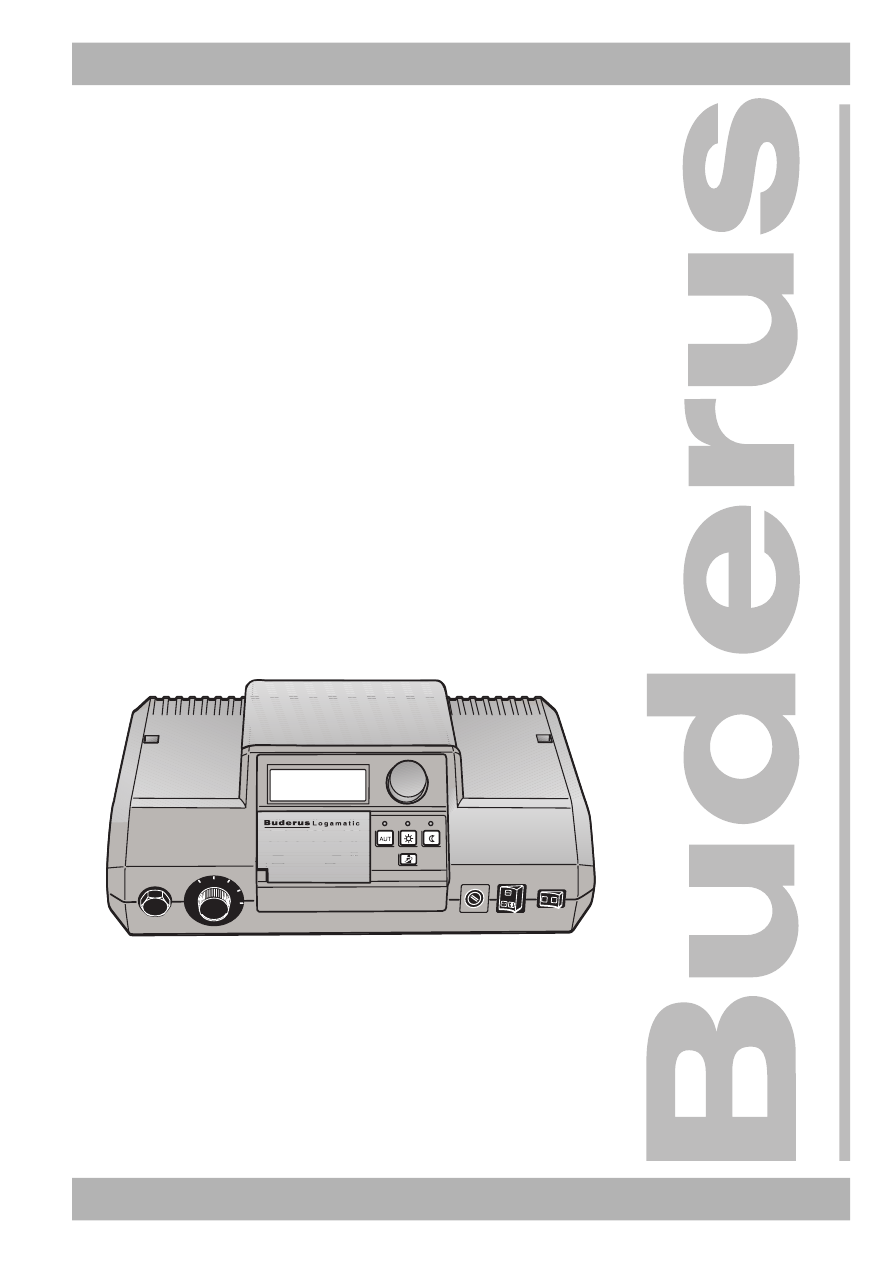
6303 9023 – 09/2002 RU
Уровень пользователя
Внимательно прочитайте перед обслуживанием
Инструкция по эксплуатации
Системы
управления
Logamatic 2107,
Logamatic 2107 M
AUT
90
70
60
50
I
0
1…7
Tag
Zeit
Temp
Urlaub
Auswahl
So/Wi
Anzeige
Install
Zurück
PROG
ABTOPEЖUM
11:15
21
Страница:
(1 из 64)
навигация

1

2

3

4

5

6

7

8

9

10

11

12

13

14

15

16

17

18

19

20

21

22

23

24

25

26

27

28

29

30

31

32

33

34

35

36

37

38

39

40

41

42

43

44

45

46

47

48

49

50

51

52

53

54

55

56

57

58

59

60

61

62

63

64
Оглавление инструкции
- Страница 1 из 65
6303 9023 – 09/2002 RU Уровень пользователя Инструкция по эксплуатации Системы Logamatic 2107, управления Logamatic 2107 M ABTOPEЖUM 11:15 21 1…7 Tag Urlaub Anzeige 90 Zeit Temp PROG Auswahl So/Wi Install Zurück AUT 7 0 60 50 I 0 Внимательно прочитайте перед обслуживанием - Страница 2 из 65
Предисловие Оборудование соответствует основным требованиям нормативных документов и предписаний. Соответствие подтверждено. Необходимые документы и декларация о соответствии хранятся на фирмеизготовителе. Эта инструкция по эксплуатации распространяется только на системы управления Logamatic - Страница 3 из 65
Содержание 1 Введение 2 Что нужно знать об отопительной установке . 3 Советы по экономичному отоплению . 4 Техника безопасности при работе с системой управления . 4.1 4.2 4.3 4.4 . . . . . . . . . . . . . . . . . . . . . . . . . . . . . . . . . . . . . . . . . . . . . . . . . .5 Применение по - Страница 4 из 65
Содержание 10 Устранение ошибок и неисправностей. 11 Работа в случае неисправности . . . . . . . . . . . . . . . . . . . . . . . . 55 . . . . . . . . . . . . . . . . . . . . . . . . . . . . . 58 12 Протокол настройки. . . . . . . . . . . . . . . . . . . . . . . . . . . . . . . . . . . . . . . . 60 - Страница 5 из 65
Введение 1 1 Введение Останавливая свой выбор на системе управления Logamatic 2107 или 2107 M, Вы приобретаете простой в использовании прибор, с помощью можно регулировать работу отопительной установки. При минимальном потреблении энергии Вы достигаете оптимальный тепловой комфорт. Система - Страница 6 из 65
1 Введение Об этой инструкции В главе 2 некоторые пояснения о том, как работает отопление, которые дают представление об отопительных установках и их регулировании. Глава 3 приведены советы по экономичному отоплению. В главе 4 даны указания по технике безопасности при работе с системой управления. - Страница 7 из 65
Что нужно знать об отопительной установке 2 2 Что нужно знать об отопительной установке Почему нужно ближе познакомиться с отопительной установкой? Отопительные установки нового поколения предлагают множество функций, используя которые Вы экономите энергию без ущерба собственному комфорту. Первый - Страница 8 из 65
2 Что нужно знать об отопительной установке На рисунке 1 изображен отопительный контур с принудительной циркуляцией. Горелка (2) подогревает воду в котле (1). Насос (3) перекачивает эту котловую воду по подающей линии (4) к отопительным приборам (6). Вода проходит через отопительные приборы и - Страница 9 из 65
Что нужно знать об отопительной установке 2 Зачем нужна система регулирования отопления? Система регулирования отопительной установки обеспечивает поддержание теплового комфорта и при этом следит за экономным расходом топлива и электроэнергии. При потребности в горячей воде или для повышении - Страница 10 из 65
2 Что нужно знать об отопительной установке Регулирование в зависимости от наружной температуры При этом виде регулирования определяющим показанием для температуры подающей линии является только температура, измеренная наружным датчиком. Колебания комнатной температуры из-за инсоляции, - Страница 11 из 65
Что нужно знать об отопительной установке 2 Зачем нужен таймер? Что такое отопительные контуры? Современные отопительные установки оснащены таймером для экономии энергии. Используя таймер, Вы можете установить, чтобы переключение с одного режима на другой происходило автоматически в определенное - Страница 12 из 65
3 3 Советы по экономичному отоплению Советы по экономичному отоплению Здесь приведены советы по экономичному и комфортному отоплению: – Топите только тогда, когда Вам необходимо тепло. Пользуйтесь программами, предустановленными в системе управления (стандартными программами) или Вашими - Страница 13 из 65
Техника безопасности при работе с системой управления 4 Техника безопасности при работе с системой управления 4.1 Применение по назначению 4 Система управления Logamatic 2107 предназначена для осуществления управления и контроля за отопительными установками в домах на одну семью или в домах рядовой - Страница 14 из 65
5 5 Работа системы управления Работа системы управления Вы можете выполнять настройки отопительной установки на системе управления Logamatic 2107. Наглядное расположение элементов управления упрощает работу с прибором. Элементы управления Logamatic 2107 и 2107 M 9 8 10 7 ABTOPEЖUM 11:15 21 6 0 9 A - Страница 15 из 65
Работа системы управления 5 Предохранительный ограничитель температуры Предохранительный ограничитель температуры (STB) служит для того, чтобы отопительная установка не работала со слишком высокой температурой, на которую она не рассчитана. Регулятор температуры котловой воды Обычно регулятор - Страница 16 из 65
5 Работа системы управления Кнопки основных функций Этим кнопками управляются основные функции. 1 Рис. 5 2 3 4 Кнопки основных функций Поз. 1: автоматический режим по таймеру Поз. 2: нормальный отопительный режим (дневной режим) Поз. 3: тест дымовых газов (для замеров параметров дымовых газов) Поз. - Страница 17 из 65
Работа системы управления 5 Кнопки дополнительных функций Эти кнопки нужны для установки, например, дня недели, времени, температуры и т.д. 1 2 3 4 5 6 7 8 11 Рис. 6 10 9 Кнопки дополнительных функций Поз. 1: кнопка «День недели» – ввод дня недели Поз. 2: кнопка «Отпуск» – ввод функции Отпуск Поз. - Страница 18 из 65
5 Работа системы управления Дисплей На дисплее показываются заданные и измеренные параметры и температуры, например, при закрытой крышке измеренная комнатная температура. 1 2 °F°C 1 2 1234567 5 Рис. 7 Поз. 1: 4 3 Дисплей текст индикации Поз. 2: летний режим радиочасы °F °C единицы измерения - Страница 19 из 65
Основные функции 6 6 Основные функции В этой главе приведена информация о пуске в эксплуатацию системы управления Logamatic 2107, ее выключении и об основных принципах работы с ней. ABTOPEЖUM 11:15 21 0 9 A U T 7 0 0 6 50 I 90 0 AUT 7 0 60 50 2 4 1 3 Рис. 8 6.1 Кнопки, необходимые для пуска в - Страница 20 из 65
6 6.2 Основные функции Выключение системы управления Установите пусковой выключатель в положение «0» (рис. 8, поз. 4). ПОВРЕЖДЕНИЕ КОТЛА вследствие замерзания установки. ОСТОРОЖНО! Оставляем за собой право на изменения! 20 Функция защиты от замерзания активна только при включенной системе - Страница 21 из 65
Основные функции 6.3 6 Стандартная индикация и рабочие параметры Das neue Displ ay! ABTOPEЖUM °C 7 16:30 22 В нормальном режиме на дисплее показаны день недели, время, режим работы и требуемая комнатная температура. Вывод на дисплей других рабочих параметров Поворачивая ручку переключателя, можно - Страница 22 из 65
6 6.4 Основные функции Изменение режима работы ABTOPEЖUM 11:15 21 Кнопки на системе управления 2107 (см. рисунок), имеют такие же функции, как и кнопки на дистанционном управлении. На пульте дитанционного управления можно задать режим работы для отопительных контуров, которые оснащены таким - Страница 23 из 65
Основные функции 6 Выбор автоматического режима Вместе с зеленым светодиодом (LED) над кнопкой «AUT» также горит светодиод над кнопкой «Дневной режим» или «Ночной режим» – в зависимости от того, какой режим отопления в данный момент включен. Смена нормального режима на режим с пониженной - Страница 24 из 65
6 6.5 Основные функции Установка комнатной температуры YΠPΠYλbT 1 Если подключено дистанционное управление, то комнатную температуру для нормального (дневного) режима и для режима с пониженной температурой (для ночного режима) можно установить только на дистанционном управлении для соответствующего - Страница 25 из 65
Основные функции 6 Ввод комнатной температуры (отопительные контуры без дистанционного управления) Если комнатная температура для Вас высока, то можно уменьшить ее значение. При слишком низкой комнатной температуре ее можно повысить. Нажать кнопку «Отопительный контур» и, удерживая ее нажатой, - Страница 26 из 65
6 6.6 Основные функции Установка температуры горячей воды ABTOPEЖUM 11:15 21 С помощью системы управления Logamatic 2107 можно экономично нагревать воду для контура горячего водоснабжения. Для этого предусмотрено приготовление горячей воды по таймеру. Вы можете включить приготовление горячей воды, - Страница 27 из 65
Основные функции 6 Установка температуры горячей воды Удерживать нажатой кнопку «Гор.вода» и ручкой управления установить нужную температуру горячей воды (здесь: «50 °C»). + ГOP BODA °C 50 Теперь температура горячей воды установлена на 50 °C. Отпустить кнопку «Горячая вода». Температура горячей - Страница 28 из 65
7 7 Дополнительные функции Дополнительные функции В этой главе приведена информация по дополнительным функциям. К ним относится, например, информация по настройкам солнечного коллектора и по отопительным программам. 7.1 Изменение рабочих режимов солнечного коллектора Если система управления - Страница 29 из 65
Дополнительные функции 7 Ручной режим работы солнечного коллектора Функциональный тест солнечного коллектора. В этом режиме установка не работает автоматически. Насос солнечного коллектора включается вручную, если это позволяет состояние установки (например, если коллектор не достаточно горячий). - Страница 30 из 65
7 7.2 Дополнительные функции Выбор стандартной программы Что значит программа отопления? ABTOPEЖUM 11:15 21 Программа отопления заботится об автоматической смене режимов работы: нормального (дневного) и режима с пониженной температурой (ночного) в определенное время. Автоматический переход - Страница 31 из 65
Дополнительные функции 7 Обзор стандартных программ Выберите стандартную программу, которая наилучшим образом соответствует Вашим потребностям. Если Вы хотите иметь индивидуальную программу, то задайте собственные значения времени включения и выключения. На выбор предлагаются следующие восемь - Страница 32 из 65
7 Дополнительные функции Выбор стандартной программы (выбор программы для отопительного контура) Открыть крышку. Удерживать нажатой кнопку «Отопительный контур» до появления, например, «Отопительный контур 1». + Отпустить кнопку «Отопительный контур». Нажать кнопку «PROG» и повернуть ручку - Страница 33 из 65
Дополнительные функции 7.3 7 Ввод программы Отпуск Вы можете прервать установленную отопительную программу, если, например, на следующий день отправляетесь в отпуск. В этот период Вы хотите топить меньше. ABTOPEЖUM 11:15 21 Преимущество отопительного режима с пониженной температурой (ночного - Страница 34 из 65
7 Дополнительные функции Удаление программы Отпуск Для удаления действующей программы Отпуск и перехода к нормальному режиму работы выполните следующие действия: Открыть крышку. + Удерживать нажатой кнопку «Отпуск» и повернуть ручку управления до появления на дисплее строк «OTПYCK 00». Отпустить - Страница 35 из 65
Дополнительные функции 7.4 7 Установка программы переключения режима лето/зима ABTOPEЖUM 11:15 21 В системе управления Logamatic 2107 переключение с летнего режима на зимний и наоборот происходит с некоторым запаздыванием по времени, так как сигнал от датчика наружной температуры поступает уже с - Страница 36 из 65
7 Дополнительные функции Установка переключения режима лето/зима Открыть крышку. Удерживать нажатой кнопку «Лето/зима» и повернуть ручку управления до появления «ЛETO C» и нужной «демпфированной наружной температуры». + λETO C °C 21 Отпустить кнопку «Лето/зима» для сохранения введенных данных. Этот - Страница 37 из 65
Дополнительные функции 7.5 7 Настройка постоянного режима приготовления горячей воды Установка постоянного режима ABTOPEЖUM 11:15 21 Открыть крышку. Удерживать нажатой кнопку «Отопительный контур» и повернуть ручку управления до появления строки «ГOP BODA». + ГOP BODA Отпустить кнопку «Отопительный - Страница 38 из 65
7 7.6 Дополнительные функции Изменение стандартной индикации Выберите, какая индикация должна появляться на системе управления в спокойном режиме. ABTOPEЖUM 11:15 21 Заводская настройка: Das neue Displ ay! ABTOPEЖUM °C 7 06:30 22 «ABTOPEЖUM», время, день недели, актуальная заданная комнатная - Страница 39 из 65
Дополнительные функции 7.7 7 Установка времени и дня недели Если установлено дистанционное управления со встроенным приемником радиосигналов (BFU/F), то настройка или корректировка дня недели и времени происходит автоматически. ABTOPEЖUM 11:15 21 Открыть крышку. + Удерживать нажатой кнопку «День - Страница 40 из 65
7 7.8 Дополнительные функции Переключение летнего/зимнего времени Ручной ввод летнего/зимнего времени Переустановка происходит по установленным законом правилам: ABTOPEЖUM 11:15 21 – на зимнее время: в выходные дни последней недели октября: в воскресенье в 03:00 часа на 02:00 часа (-1 час). – на - Страница 41 из 65
Дистанционное управление BFU, BFU/F 8 8 Дистанционное управление BFU, BFU/F Дистанционное управление BFU или BFU/F (дополнительное оборудование) позволяет комфортабельно регулировать работу отопительной установки из жилого помещения. 8.1 Общая информация по BFU, BFU/F Дистанционное управление имеет - Страница 42 из 65
8 8.4 Дистанционное управление BFU, BFU/F Отопительный режим с пониженной температурой (ночной режим) Отопительный режим с пониженной температурой вводится в виде разницы температур между нормальным режимом и режимом с пониженной температурой. Настройку должен выполнять специалист отопительной - Страница 43 из 65
Дистанционное управление BFU, BFU/F 8 Автоматический режим Вместе с зеленым светодиодом на кнопке «AUT» горит также светодиод на кнопке «Дневной режим» или на кнопке «Ночной режим» — в зависимости от актуального отопительного режима. Если имеются два отопительных контура, и только один из них имеет - Страница 44 из 65
8 Дистанционное управление BFU, BFU/F Ручной режим Отопительный режим с пониженной температурой (ночной режим) Вы переключаетесь на ручной режим, чтобы изменить нужную температуру. Режим индицируется зеленым светодиодом на кнопке «Ночной режим». В этом режиме отопление работает с пониженной - Страница 45 из 65
Дополнительные возможности программирования 9 9 Дополнительные возможности программирования 9.1 Изменение стандартной программы Если стандартная программа Вам не очень подходит, то ее можно изменить или поручить это специалисту отопительной фирмы. Измененная стандартная программа сохраняется под - Страница 46 из 65
9 Дополнительные возможности программирования Перенос времени переключения Если Вы внесли изменения в стандартную программу или ввели полностью новую программу, то система управления сохраняет введенные данные под названием «COGCTB. 1» для отопительного контура 1 и «COGCTB. 2» для отопительного - Страница 47 из 65
Дополнительные возможности программирования 9 Установка времени переключения. Можно ввести точки переключения (установив день недели, время и температуру) в существующую отопительную программу, например, для того, чтобы прервать фазу отопления. ABTOPEЖUM 11:15 21 1…7 УКАЗАНИЕ ДЛЯ ПОТРЕБИТЕЛЯ - Страница 48 из 65
9 Дополнительные возможности программирования CEMbЯ 1 05:30 °C 21 На дисплее появится первое время переключения стандартной программы «CEMbЯ». Повернуть налево ручку управления до появления на дисплее строки «HOB T ПEP». HOB T ПEP °C 7 —:— —Удерживать нажатой кнопку «День недели» и повернуть - Страница 49 из 65
Дополнительные возможности программирования 9 Отмена отопительного периода Отопительный период подразумевает два значения времени переключения: одного включения и одного выключения. Если Вы хотите отменить отопительный период, то нужно отменить оба времени переключения. ABTOPEЖUM 11:15 21 До - Страница 50 из 65
9 Дополнительные возможности программирования Повернуть ручку переключателя до появления времени переключения отопительного периода, который Вы хотите отменить, например, «11:30». Удерживать нажатой кнопку «Время» и ручкой управления установить нужное значение (здесь: «13:00»). + ΠOλDEHb 1 13:00 - Страница 51 из 65
Дополнительные возможности программирования 9.2 9 Объединение отопительных периодов Отопительный период подразумевает два значения времени переключения: одного включения и одного выключения. Чтобы объединить два отопительных периода, идущих один за другим, установите время выключения первого - Страница 52 из 65
9 Дополнительные возможности программирования Повернуть ручку переключателя до появления времени выключения отопительного периода, который нужно объединить с другим отопительным периодом (здесь: «13:00»). Удерживать нажатой кнопку «Время» и ручкой управления установить нужное значение (здесь: - Страница 53 из 65
Дополнительные возможности программирования 9.3 9 Создание новой программы отопления Можно также создать новую отопительную программу, которая полностью соответствует Вашим потребностям. Новая программа сохраняется под названием «COGCTB. 1». ABTOPEЖUM 11:15 21 Ввод времени переключения, например, - Страница 54 из 65
9 Дополнительные возможности программирования Удерживать нажатой кнопку «Темп.» и повернуть ручку управления до появления нужной комнатной температуры для нормального отопительного режима, например, «21 °C». + HOB T ΠEP 1 05:00 °C 21 HOB T ΠEP °C 7 —:— — Отпустить кнопку «Темп.». Время - Страница 55 из 65
Устранение ошибок и неисправностей 10 10 Устранение ошибок и неисправностей При возникновении неисправностей отопительной установки на дисплее системы управления появляются сообщения об этом. Некоторые неисправности можно устранить самостоятельно (см. главу «Таблица неисправностей» на стр. 56). Для - Страница 56 из 65
10 Устранение ошибок и неисправностей Таблица неисправностей Сообщение о неисправности Фактическая ситуация Рекомендации – Не работает отопление. Устранить неисправность в соответствии с указаниями в документации на отопительный котел или горелку. – Не работает отопление. Вызвать специалиста - Страница 57 из 65
Устранение ошибок и неисправностей Сообщение о неисправности 10 или YΠPΠYλbT 2 Err. DATTEMKOT Err. DATHAPTEM Err. DAT ГBC Err. DATΠODλUH Err. DATOTXГA3 Err. DAT CОλH Err. DAT ГВС С Err. Рекомендации Неисправности дистанционного управления YΠPΠYλbT 1 Err. Фактическая ситуация Вызвать специалиста - Страница 58 из 65
11 Работа в случае неисправности 11 Работа в случае неисправности При неисправности в управлении можно продолжать эксплуатировать систему отопления. ABTOPEЖUM 11:15 21 ОПАСНО ДЛЯ ЖИЗНИ 0 9 AT U 7 0 60 I 50 ПРЕДУПРЕЖДЕНИЕ! из-за возможного поражения электрическим током. 0 Никогда не вскрывайте - Страница 59 из 65
Работа в случае неисправности 11 При возникновении неисправностей нужно сразу же уведомить специалистов отопительной фирмы, обслуживающей котел. Они обеспечат квалифицированное техническое обслуживание. Вы сможете им помочь, если точно опишите характер неисправностей. Ручной режим В ручном режиме - Страница 60 из 65
12 Протокол настройки 12 Протокол настройки Рабочие параметры Диапазон ввода Заводская установка Заводские программы CEMbЯ PAHbШE ΠO3ЖE YTPO BEЧEP ПОЛДЕНЬ XOЛOCTЯK HOBAЯ COGCTB. CEMbЯ Горячая вода 30 °C–90 °C 60 °C Переключение лето/зима постоянно лето постоянно зима 10 °C–30 °C 17 °C Дневная - Страница 61 из 65
Тест дымовых газов 13 13 Тест дымовых газов Тест дымовых газов должен проводить только мастер из службы контроля за дымовыми трубами. Этот тест проводится один раз в год. ABTOPEЖUM 11:15 21 0 9 AT U 7 0 60 50 90 0 AUT 7 0 50 1 I 60 Мастер проводит замеры на отопительной установке. Отдельные - Страница 62 из 65
14 Алфавитный указатель 14 Алфавитный указатель А Аварийный режим . . . . . . . . . . . . . . . . . 58 Автоматический режим . . . . . . . . . . . .23, 42 Автоматический режим солнечного коллектора . . . . . . . . . . . . . . . . . . . . . 28 Б Бак-водонагреватель . . . . . . . . . . . . . . . 7 В - Страница 63 из 65
Алфавитный указатель 14 Ручка управления . . . . . . . . . . . . . . . . . 15 Ручной режим . . . . . . . . . . . . . . . . . . . 59 Ручной режим солнечного коллектора . . . . . 29 С Система регулирования . . . . . . . . . . . . . . 7 Солнечный коллектор Выкл. . . . . . . . . . . . 29 Стандартные - Страница 64 из 65
Специализированная отопительная фирма: Buderus Heiztechnik GmbH, 35573 Wetzlar http://www.heiztechnik.buderus.de E-Mail: info@heiztechnik.buderus.de - Страница 65 из 65
Предложите, как улучшить StudyLib
(Для жалоб на нарушения авторских прав, используйте
другую форму
)
Ваш е-мэйл
Заполните, если хотите получить ответ
Оцените наш проект
1
2
3
4
5