-
Contents
-
Table of Contents
-
Bookmarks
Quick Links
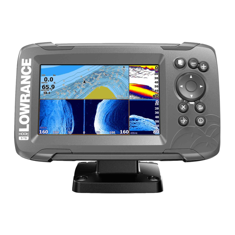
Hook2 Series
Operator Manual
5 HDI, 5 TS, 7X GPS TS, 7 HDI, 7 TS, 9 TS, 9 HDI,
and 12 TS
ENGLISH
www.lowrance.com
Related Manuals for Lowrance 5 HDI
Summary of Contents for Lowrance 5 HDI
-
Page 1
Hook2 Series Operator Manual 5 HDI, 5 TS, 7X GPS TS, 7 HDI, 7 TS, 9 TS, 9 HDI, and 12 TS ENGLISH www.lowrance.com… -
Page 3
This manual represents the product as at the time of printing. Navico Holding AS and its subsidiaries, branches and affiliates reserve the right to make changes to specifications without notice. Trademarks ® ® Lowrance and Navico are registered trademarks of Navico Holding ® C-MAP is a registered trademark of C-MAP. -
Page 4: About This Manual
This manual is a reference guide for operating the following Hook models: 5 HDI, 5 TS, 7X GPS TS, 7 HDI, 7 TS, 9 TS, 9 HDI, and 12 TS. As a result, screenshots of menus and dialogs may not match the look of your unit.
-
Page 5
This manual is written for software version 1.0. The manual is continually updated to match new software releases. The latest available manual version can be downloaded from www.lowrance.com. The Software version The software version currently on this unit can be found in the About dialog. -
Page 6
Preface | Hook² Series Operator Manual… -
Page 7: Table Of Contents
Contents 11 Introduction Front controls The Home page Application pages 15 Basic operation System Controls dialog Turning the system on and off Display illumination Stop sonar Using menus and dialogs Using the cursor on the panel Creating a Man Overboard waypoint Screen capture 19 Customizing your system Customizing the Home page wallpaper…
-
Page 8
34 GPS plotter GPS plotter page Vessel symbol GPS plotter page scale Panning the GPS plotter image GPS view options Waypoints, Routes, and Trails Navigating GPS plotter settings 38 Waypoints, Routes, and Trails Waypoints, Routes, and Trails dialogs Waypoints Routes Trails 46 Navigating Navigate to cursor position… -
Page 9
Viewing StructureScan history Recording StructureScan data Setting up the StructureScan image 65 DownScan The DownScan image Zooming the DownScan image Using the cursor on the DownScan panel Viewing DownScan history Customize the image settings 70 StructureMap The StructureMap image Activating Structure overlay StructureMap tips Recording StructureScan data Using StructureMap with mapping cards… -
Page 10: Contents | Hook² Series Operator Manual
85 Simulator Demo mode Simulator source files Advanced simulator settings Contents | Hook² Series Operator Manual…
-
Page 11: Introduction
Introduction Front controls Pages — Press to activate the Home page. Zoom in/out — Press to zoom the image. Press both keys simultaneous to create a MOB (Man Over Board) waypoint at the vessel’s position. Ú Note: Creating a MOB waypoint is not available on 4x Sonar only models.
-
Page 12: The Home Page
Micro SD card Depending on model the card reader is located either on the side or on the front. The Home page The Home page is accessed from any operation by a short press on the Pages key. Ú Note: Page icons on the Home page vary with model type.
-
Page 13: Application Pages
Application page icons — Select a button to display the application page. Customize — Activate customize mode to delete or modify custom pages. Application pages Application panel Menu — Panel specific menu. System Controls dialog — Quick access to basic system settings.
-
Page 14
Multiple panel custom pages You can have up to 4 panels on a custom page. Refer to «Adding new custom pages» on page 20. 2 panels page 3 panels page 4 panels page Panel sizes in a multiple panel page can be adjusted from the System Controls dialog. -
Page 15: Basic Operation
Basic operation System Controls dialog The System Controls dialog provides quick access to basic system settings. You display the dialog by making a short press on the Power key. The icons displayed on the dialog can vary. For example, the adjust splits option is only available if you are viewing a multiple panel page when you open the System Controls dialog.
-
Page 16: Display Illumination
Switch from Standby mode to normal operation by a short press on the Power key. Display illumination Brightness The display backlighting can be adjusted at any time from the System Controls dialog. You can also cycle the preset backlight levels by short presses on the Power key.
-
Page 17: Using The Cursor On The Panel
Numeric and alphanumeric keyboards are automatically displayed when required for entering user information in dialogs. A dialog is closed by saving or cancelling the entry. A dialog can also be closed by pressing the Exit (X) key. Using the cursor on the panel The cursor can be used to mark a position, and to select items.
-
Page 18: Screen Capture
Cancel navigation to MOB The system continues to display navigational information towards the MOB waypoint until you cancel the navigation from the menu. Display MOB waypoint information You can display MOB information by selecting the MOB waypoint so the MOB waypoint pop-up is displayed. Open the menu and select the Info option in the menu.
-
Page 19: Customizing Your System
Customizing your system Customizing the Home page wallpaper The Home page’s wallpaper can be customized. You can select one of the pictures included with the system, or you can use your own picture in .jpg or .png format. The images can be available on any location that can be seen in the files browser.
-
Page 20: Adding New Custom Pages
Edit overlay data Use the Edit overlay option on the System Controls dialog to access edit menu options to: • Add a new data overlay to the active panel. • Delete a selected data overlay. • Change a selected data overlay to display different data. •…
-
Page 21: Edit Or Delete Custom Pages
top left corner of the panel you want to move. Press the Menu/Enter key. A larger arrows icon is displayed. Use the Arrow keys to move the highlighted panel. Press the Menu/ Enter key to save your adjustment. Save the page layout. The system displays the new custom page, and an icon for the new page is included on the Home page.
-
Page 22
Use the Arrow keys to move the split to the desired position Press the Menu/Enter key to save the split adjustment. Customizing your system | Hook² Series Operator Manual… -
Page 23: Charts
Charts Ú Note: Charts are not available on 7x TS models. Instead the GPS function is available, refer to «GPS plotter» on page 34. The chart function displays your vessel’s position relative to land and other chart objects. On the chart panel you can plan and navigate routes, and place waypoints.
-
Page 24: Selecting Chart Type
Chart range scale Range rings interval (only displayed when Range rings are turned on) * Optional chart items. You turn the optional chart items on/off individually from the Chart settings dialog. Selecting chart type You specify the chart type shown on the Chart panel by selecting one of the available chart types in the chart settings dialog.
-
Page 25: Navigating
Navigating You can use the page for navigating to the cursor, to a waypoint, or navigate a route. Refer to «Navigating» on page 46. Displaying information about chart items When you position the cursor over a chart item, waypoint, trail or a route, basic information for the selected item is displayed as a pop- Ú…
-
Page 26: Chart Overlay
Chart overlay Structure (StructureMap) information can be displayed as overlay on your chart panel. Ú Note: Structure overlay (StructureMap) is only available on models that have TripleShot/SideScan capability. When Structure overlay is selected, the chart menu expands to include basic menu functions for the overlay. Refer to «StructureMap» on page 70.
-
Page 27: C-Map Specific Chart Options
C-MAP specific chart options Chart overlay, orientation, and look ahead options (previously described in this section) are common to both C-MAP and Navionics charts. The following describe C-MAP specific chart options. Chart detail Full • All available information for the chart in use. Medium •…
-
Page 28: Navionics Charts
Navionics charts Some Navionics features require the most current data from Navionics. For those features, a message is displayed stating that the feature is unavailable if you do not have the appropriate Navionics charts or chart card inserted. For more information on what is required for these features, refer to www.navionics.com.
-
Page 29
Navionics specific chart options Chart overlay, orientation, and look ahead options (previously described in this section) are common to both C-MAP and Navionics charts. The following describe Navionics specific chart options. Community edits Toggles on the chart layer including Navionics edits. These are user information or edits uploaded to Navionics Community by users, and made available in Navionics charts. -
Page 30
Dynamic tide information Dynamic current information The following icons and symbology are used: Current speed The arrow length depends on the rate, and the symbol is rotated according to flow direction. Flow rate is shown inside the arrow symbol. The red symbol is used when current speed is increasing, and the blue symbol is used when current speed is decreasing. -
Page 31
Fishing range Select a range of depths between which Navionics fills with a different color. This allows you to highlight a specific range of depths for fishing purposes. The range is only as accurate as the underlying chart data, meaning that if the chart only contains 5 meter intervals for contour lines, the shading is rounded to the nearest available contour line. -
Page 32: Chart Settings
Safety depth The Navionics charts use different shades of blue to distinguish between shallow and deep water. Safety depth, based on a selected limit, is drawn without blue shading. Ú Note: The built in Navionics database features data down to 20 m, after which it is all white.
-
Page 33: Range Rings
Range Rings The range rings can be used to present the distance from your vessel to other panel objects. The range scale is set automatically by the system to suit the panel scale. Grid lines Turns on/off viewing of longitude and latitude grid lines on the panel.
-
Page 34: Gps Plotter
GPS plotter Ú Note: The GPS plotter page is available on 7x TS models only. The GPS plotter page displays your vessel’s position. On the GPS plotter page you can plan and navigate routes, see your vessel’s trail, and place waypoints. GPS plotter page Data overlay (Can be edited, moved or removed.
-
Page 35: Vessel Symbol
Vessel symbol When the system has a valid GPS position lock, the vessel symbol indicates vessel position. If no GPS position is available, the vessel symbol includes a question mark. GPS plotter page scale You zoom in and out on the GPS plotter page by using the Zoom keys.
-
Page 36: Waypoints, Routes, And Trails
North up Course up North up Displays the GPS plotter image with north upward. Course up The GPS plotter image direction is depending on if navigating or not: • when navigating: the desired course is oriented up • if not navigating: the direction the vessel is actually traveling (COG) is oriented up Look ahead Moves the vessel icon on the panel to maximize your view ahead of…
-
Page 37: Gps Plotter Settings
GPS plotter settings Pop-up information Selects whether basic information for panel items is displayed when you select the item. Range Rings The range rings can be used to present the distance from your vessel to other panel objects. The range scale is set automatically by the system to suit the panel scale.
-
Page 38: Waypoints, Routes, And Trails
Waypoints, Routes, and Trails Waypoints, Routes, and Trails dialogs The Waypoints, Routes, and Trails dialogs give access to advanced edit functions and settings for these items. The dialogs are accessed from the Tools panel on the Home page. Select the menu icon on the dialog to access additional options. Waypoint options Routes options Trails options…
-
Page 39: Moving A Waypoint
longitude coordinates. A waypoint is used to mark a position you later may want to return to. Two or more waypoints can also be combined to create a route. Saving waypoints Press and hold the Cursor/Waypoint key to save a new waypoint. •…
-
Page 40: Routes
Delete a waypoint You can delete a waypoint from the Edit Waypoint dialog or by selecting the Delete menu option when the waypoint is activated. The Edit Waypoint dialog is activated by positioning the cursor over the waypoint, selecting the waypoint in the menu, and then the delete menu option.
-
Page 41: Delete A Route
Maneuver the cursor over the route in the panel. The route pop- up is displayed. Press the Menu/Enter key and use the Arrow keys to select the route in the menu. The menu expands with additional options. — The edit option allows you to move and remove routepoints on the panel.
-
Page 42: Converting Trails To Routes
You can also insert existing waypoints in an existing route from the Edit Routes dialog. From the Edit Routes dialog, select the routepoint in the list where you want to insert the waypoint and press the Menu/Enter key. Converting Trails to Routes You can convert a trail to a route from the Edit Trail dialog.
-
Page 43: Trails
The Edit Route dialog You can add and remove routepoints, and change route properties using the Edit Route dialog. This dialog is activated by placing the cursor over the route and selecting the route in the menu. The dialog can also be accessed by selecting the route tab in the dialog displayed when you select the Waypoint, Routes, and Trails tool on the Home page.
-
Page 44
From the factory, the system is set to automatically track and draw the vessel’s movement on the panel. The system continues to record the trail until the length reaches the maximum points, and then automatically begins overwriting the oldest points. The automatic tracking function can be turned off from the Edit Trails dialog. -
Page 45
You can color trails by selecting the trail in the Trails dialog and set the color in the Edit Trail dialog. Waypoints, Routes, and Trails | Hook² Series Operator Manual… -
Page 46: Navigating
Navigating The navigation function included in the system allows you to navigate to the cursor position, to a waypoint, or along a predefined route. For information about positioning waypoints and creating routes, refer to «Waypoints, Routes, and Trails» on page 38. When you select to navigate to the cursor position, to a waypoint or a predefined route, the Navigation option appears in the menu.
-
Page 47: Navigation Settings
Navigation settings Arrival radius Sets an invisible circle around the destination waypoint. The vessel is considered arrived at the waypoint when it is within this radius. XTE limit This setting defines how far the vessel can deviate from the selected route, if the vessel goes beyond this limit, an alarm is activated.
-
Page 48
Specify one of the following logging types in the Navigating Settings dialog: Auto — the unit positions a point automatically when a course • change is registered. Distance — select the Distance field and enter the distance you • want to record. Time — select the Time field and enter the time you want to •… -
Page 49: Sonar
Sonar The Sonar function provides a view of the water and bottom beneath your vessel, allowing you to detect fish and examine the structure of the bottom. The Sonar image Fish arches Speed over ground* Depth* Water Temperature* Frequency Bottom Range scale * Optional Sonar data overlay that you can modify.
-
Page 50: Zooming The Image
Zooming the image You can zoom the image by using the Zoom keys. The zoom level is shown on the bottom left side of the image. When zooming with no active cursor, the sea floor is kept near the bottom of the screen. If the cursor is active, the unit zooms where the cursor is pointed.
-
Page 51
The range The range setting determines the water depth that is visible on the screen. Frequency The unit supports several transducer frequencies. Available frequencies depend on the transducer model that is connected. Sensitivity Increasing Sensitivity shows more detail on the screen. Decreasing Sensitivity displays less. -
Page 52
Advanced options Ping speed Ping speed controls the rate the transducer transmits the signal into the water. By default, the ping speed is set to max. It may be necessary to adjust the ping speed to limit interference or to adjust for specific fishing conditions. -
Page 53: More Options
More options Split screen options Split screen options are available on the split screen sub-menu. Zoom Zoom level Zoom bars The Zoom mode presents a magnified view of the sounder image on the left side of the panel. By default, the zoom level is set to 2x. You can zoom up to 8x, using the Zoom keys.
-
Page 54: Amplitude Scope
range scale. The scaling factor for the image on the left side of the panel is adjusted as described for the Zoom option. Flasher The Flasher mode shows a flasher-style sonar view in the left panel and a normal sonar view in the right panel. Amplitude scope The Amplitude scope is a display of real-time echoes as they appear on the panel.
-
Page 55: Start Recording Sonar Log Data
When activated, the Sonar menu expands to include basic DownScan options. Measuring distance The cursor can be used to measure the distance between the position of two observations on the image. Position the cursor on the point from where you want to measure the distance Start the measuring function from the More options menu option…
-
Page 56: Stop Recording Sonar Log Data
When the data is being recorded, there is a flashing red symbol in the top left corner and a message appears periodically at the bottom of the screen. Filename Specify the name of the recording (log). File format Select a file format from the drop-down, slg (Sonar only), xtf (Structure only*), or sl2 (Sonar and Structure).
-
Page 57: Viewing The Recorded Sounder Data
Ú Note: If you have selected the Create StructureMap option in the record sonar dialog, the Convert structure log to map dialog is displayed when you select Stop in the Logging Sonar dialog. Select Convert to create a smf file in the Log folder. Refer to «Files»…
-
Page 58: Sonar Settings
Sonar settings Log sonar Select to start and stop recording of Sonar data. For more information, refer to «Start recording sonar log data» on page 55. View Sonar log Used to view sonar recordings. The log file is displayed as a paused image. You control the scrolling and display from the Control menu option.
-
Page 59
Lowest point of vessel offset: Set the distance from the transducer to the lowest point of the boat in the water — this should be set as a negative value. For example, — 0.3 m (-1 ft). Depth below surface (waterline) offset: Set the distance from the transducer to the surface — this should be set as a positive value. -
Page 60: Structurescan
StructureScan StructureScan uses high frequencies to provide a high resolution, picture-like image of the seabed. You must have a TripleShot enabled unit to use StructureScan features. The StructureScan image The view The StructureScan image can be set up to show left side, right side, or both left and right side scanning.
-
Page 61: Using The Cursor On The Structurescan Panel
Using the cursor on the StructureScan panel By default, the cursor is not shown on the StructureScan image. To position the cursor on the image, press the Cursor/Waypoint key. Use the Arrow keys to position the cursor. When you position the cursor on a SideScan image, the screen pauses, and the cursor information window is activated.
-
Page 62: Recording Structurescan Data
Recording StructureScan data You can record StructureScan data and save the file internally in the unit, or onto a memory card as described in «Start recording sonar data» on page 55. Setting up the StructureScan image By default the unit is set to Auto mode, and most settings are automated.
-
Page 63
Ú Note: We recommend you use Auto contrast. To adjust the contrast setting: Select the contrast option in the menu Select Auto contrast and press the Menu/Enter key to turn off auto-contrast Use the Arrow keys to highlight the adjustment bar and press the Menu/Enter key to activate it Use the Arrow keys to adjust the setting Press the Menu/Enter key to save your settings… -
Page 64
More options Flipping the Structure image left/right If required, the left/right SideScanning images can be flipped to match the direction of the transducer installation. Range Lines Range lines can be added to the image to make it easier to estimate distance. -
Page 65: Downscan
DownScan DownScan provides detailed images of structure and fish directly below your boat, down to 91 m (300 ft) at 455 kHz and 46 m (150 ft) at 800 kHz. The DownScan image Speed over ground Depth Temperature Frequency Depth Range scale Zooming the DownScan image You can zoom a DownScan image by using the Zoom keys.
-
Page 66: Viewing Downscan History
cursor is shown in the bottom row of the cursor information window. The cursor depth is shown to the left of the cursor position. To remove the cursor and the cursor elements from the panel, press the Cursor/Waypoint key. GoTo cursor You can navigate to a selected position on the image by positioning the cursor on the panel, then using the Goto Cursor option in the menu.
-
Page 67
Custom mode options Range The range setting determines the water depth that is visible on the image. Auto range By default, the range is set to Auto. With Auto, the system automatically displays the whole range from the water surface to the bottom. -
Page 68
Advanced options Surface clarity Wave action, boat wakes and temperature inversions can cause on- screen clutter near the surface. The surface clarity option reduces surface clutter by decreasing the sensitivity of the receiver near the surface. Ú Note: By default, surface clarity is set to Low, for optimal image return and clarity. -
Page 69
the cursor from the image and the image resumes to normal scrolling. DownScan | Hook² Series Operator Manual… -
Page 70: Structuremap
StructureMap Ú Note: StructureScan overlay (StructureMap) is only available on models that have TripleShot transducers. The StructureMap feature overlays SideScan images from a StructureScan source on the map. This makes it easier to visualize the underwater environment in relation to your position, and aids in interpreting SideScan images.
-
Page 71: Structuremap Tips
Ú Note: Structure overlay can also be activated by selecting a saved StructureMap file in the files browser. StructureMap tips • To get a picture of taller structures (a wreck, etc.) — do not drive over it, instead, steer the boat so the structure is on the left or right side of your vessel.
-
Page 72: Structure Options
When using StructureMap with mapping cards, copy the StructureMap (.smf ) files to the unit’s internal memory. We recommend keeping copies of StructureMap files on external mapping cards. Structure options You adjust the StructureMap settings from the Structure options menu. The menu is available when Structure overlay is enabled. Not all options are available when saved StructureMap files are used as the source.
-
Page 73: Alarms
Alarms Alarm system The system continuously checks for dangerous situations and system faults while the system is running. When an alarm situation occurs, an alarm message pops up on the screen. If you have enabled the siren, the alarm message is followed by an audible alarm.
-
Page 74: Alarms Dialog
However, the alarm remains active in the alarm listing until the reason for the alarm has been removed. Disable • Disables the current alarm setting. The alarm does not show again unless you turn it back on in the Alarms dialog. There is no time-out on the alarm message or siren.
-
Page 75: Tools
Tools By default, the Tools panel includes icons used for accessing options and tools that are not specific to any panel. The Tools panel is located on the Home page. Settings Provides access to application and system settings. System settings The system settings provides access to the following: Language Controls the language used on this unit for panels, menus, and…
-
Page 76
Key beeps Controls the loudness of the beep sound when a key is pressed. Default setting: Loud Time Controls the local time zone offset, and the format of the time and date. Datum Ú Note: Charts are not available on 7x TS models. Most paper charts are made in the WGS84 format, which also is used by the unit. -
Page 77
Advanced Shows a panel with more advanced settings. Used for setting how your system displays various user interface information. In addition, controls which features are shown in the interface. About Displays copyright information, software version, and technical information for this unit. The Support option accesses the service assistant, refer to «Service assistant»… -
Page 78: Waypoints/Routes/Trails
Waypoints/routes/trails List of waypoints, routes, and trails with details. Select the waypoint, route, or trail you want to edit or delete. Info Access to Sun/moon, Tides and Trip information. Sun, Moon Displays sunrise, sunset, moonrise and moonset for a position based on entered date and the position’s latitude/longitude.
-
Page 79
to a card. Exporting files is covered in the section «Maintenance» on page 80. Tools | Hook² Series Operator Manual… -
Page 80: Maintenance
Maintenance Preventive maintenance The unit does not contain any field serviceable components. Therefore, the operator is required to perform only a very limited amount of preventative maintenance. It is recommended that you always fit the protective sun cover when the unit is not in use. Ú…
-
Page 81: Service Assistant
Ú Note: Do not turn off the unit until the update is completed. Download the software update from www.lowrance.com to a memory card inserted in a smart device or PC connected to the internet.
-
Page 82: Backing Up Your System Data
User Data file version 3 (w/depth) • Should be used when transferring user data from one system to a legacy product (Lowrance LMS, LCX) User data file version 2 (no depth) • Can be used when transferring user data from one system to a…
-
Page 83: Export Region
Export region The export region option allows you to select the area from where you want to export data. Select export region Place the cursor over one of the boundary box corners and press the Menu/Entry key. to select it Use the Arrow keys to move the selected boundary box corner to expand the box Press the Menu/Entry key to place the corner…
-
Page 84
Ú Note: When user data is deleted and/or purged from the memory, it cannot be recovered. Importing backed up files insert the memory card containing the backed up files in the unit’s card reader. Open the Files dialog from the tool panel and select the memory card. -
Page 85: Simulator
Simulator The simulation feature lets you see how the unit works in a stationary position and without being connected to other devices. You access the simulator from Settings tool. Demo mode In this mode the unit automatically runs through the main features of the product;…
-
Page 86: Advanced Simulator Settings
Advanced simulator settings The Advanced simulator settings allows for manually controlling the simulator. GPS source Selects where the GPS data is generated from. Speed, Course and Route Used for manually entering values when GPS source is set to Simulated course or Simulated route. Otherwise, GPS data including speed and course come from the selected source file.
-
Page 87
Index Selecting chart type 24 Settings 32 About this unit 77 Zooming 24 Adding custom pages 20 Colorline Adjusting the split Sonar 52 Multiple panel pages 21 Configuring overlay data 20 Advanced system Converting trails to routes 42 settings 77 Coordinate system 76 Alarms Copying files to a card 78… -
Page 88
Cancel navigation to MOB 18 Features, how to turn on 77 Creating a MOB 17 Files to a card, copying 78 Display information 18 Files, management 78 Manual Files About 4 Viewing 78 Version 5 Flasher 54 Measuring distance 55, 64, Frequency 51 Multiple panel custom pages 14… -
Page 89
Palettes 54, 64, 68 Software upgrade 81 Ping speed 52 Software version 5 Preventive maintenance 80 Software Purging 83 How to update 81 Sonar 49 Auto mode 50 Auto sensitivity 51 Range 51 Colorline 52 Recording Customize settings 50 Start recording sonar Image 49 data 55 Sensitivity 51… -
Page 90
Range 62 Navigating settings 47 Range lines 64 Settings 44 Recording data 71 Turning the unit on and Surface clarity 63, 68 off 15 Using the cursor 61 View down or side scan 64 View history 61 Unit View options 60 Checking the Zooming 60 connectors 80… -
Page 91
Zoom Sonar 53…

PDF инструкция · 60 страниц(ы) английский
инструкцияLowrance HOOK-5

lowrance.com
ENGLISH
HOOK Series
Operation manual
HOOK-4 HOOK-5 HOOK-7 HOOK-9
Посмотреть инструкция для Lowrance HOOK-5 бесплатно. Руководство относится к категории эхолоты, 54 человек(а) дали ему среднюю оценку 8.4. Руководство доступно на следующих языках: английский. У вас есть вопрос о Lowrance HOOK-5 или вам нужна помощь? Задайте свой вопрос здесь
- nyHOOK-SERIES_OM_EN_988-11004-002_InteriorUpdate.pdf
Главная
| Lowrance | |
| HOOK-5 | 000-12656-001 | |
| эхолот | |
| 9420024146569 | |
| английский | |
| Руководство пользователя (PDF) |
Технические характеристики
| Максимальная глубина | 762 m |
| Номинальная RMS-мощность | 500 W |
| Подсветка | Да |
| Цастота | 800 kHz |
Экран
| Диагональ экрана | — « |
| Дисплей | — |
| Разрешение экрана | 480 x 480 пикселей |
Вес и размеры
Условия эксплуатации
| Водонепроницаемый | Да |
| International Protection (IP) код | IPX7 |
показать больше
Не можете найти ответ на свой вопрос в руководстве? Вы можете найти ответ на свой вопрос ниже, в разделе часто задаваемых вопросов о Lowrance HOOK-5.
Какой вес Lowrance HOOK-5?
Какой размер экрана Lowrance HOOK-5?
Какое разрешение экрана дисплея Lowrance HOOK-5?
Инструкция Lowrance HOOK-5 доступно в русский?
Не нашли свой вопрос? Задайте свой вопрос здесь
Прошивки и инструкции для эхолотов Lowrance/
-
#1
Предлагаю в этой теме выкладывать только инструкции, прошивки и прочие полезности. В идеале без обсуждений. Просто описание и собственно сам файл или ссылка на диск. (Если конечно это не возбраняется на данном форуме) Думаю многие новички скажут спасибо за ссылки. А старожилам не нужно будет отправлять новичков пользоваться поиском. Для начала выкладываю ссылку на Яндекс диск с прошивками которые у меня есть. https://yadi.sk/d/rDC6IQCqkurLxQ?w=1
Прошивки и инструкции для эхолотов Lowrance/
-
#2
Добавлю инструкцию на лайв. У кого то скачивал. Не прицепился большой файл.
Прошивки и инструкции для эхолотов Lowrance/
-
#3
Хотелось бы ещё инструкцию как правильно установить новую прошивку. Делать резет до или после, с сохранением точек и настроек, в общем с нуля для чайников.
Прошивки и инструкции для эхолотов Lowrance/
-
#4
Последнее редактирование: 28.01.2021
Прошивки и инструкции для эхолотов Lowrance/
-
#5
Прошивки и инструкции для эхолотов Lowrance/
-
#6

а зачем в этом разьеме плюс и минус? в ответной фишке на моторе только кан.
Прошивки и инструкции для эхолотов Lowrance/
-
#7
Я кстати в этом разьеме на пин 1 припаял экран витой пары .Думаю так надежнее.
Прошивки и инструкции для эхолотов Lowrance/
-
#8
только резистор не 120 а 60 ом
Прошивки и инструкции для эхолотов Lowrance/
-
#9
только резистор не 120 а 60 ом
это если сеть занята только мотором…
Прошивки и инструкции для эхолотов Lowrance/
-
#10
а зачем в этом разьеме плюс и минус? в ответной фишке на моторе только кан.
фото выкладывалось для понимания какой разьем искать. А подключение конечно только два провода надо, как на схеме. Скорее всего это провод для подключения в хаб. Точно утверждать не могу. И резисторы нужны если напрямую к эхолоту. А если в Т-коннектор сети, то там уже есть по краям они.
Прошивки и инструкции для эхолотов Lowrance/
-
#11
Инструкция к Elit TI 7-9 . Для ТИ-2 тоже подходит.Вдруг кому пригодится.
-
3.6 МБ
· Просмотры: 821
Elite7-9Ti_инструкция_ru.pdf
Прошивки и инструкции для эхолотов Lowrance/
-
#12
Еще интструкция для HOOK 2 на русском.Не много корявенький перевод но разобраться можно.
-
7.4 МБ
· Просмотры: 3 138
Hook2-Series-RUS.pdf
Прошивки и инструкции для эхолотов Lowrance/
-
#13
Предлагаю в этой теме выкладывать только инструкции, прошивки и прочие полезности. В идеале без обсуждений. Просто описание и собственно сам файл или ссылка на диск. (Если конечно это не возбраняется на данном форуме) Думаю многие новички скажут спасибо за ссылки. А старожилам не нужно будет отправлять новичков пользоваться поиском. Для начала выкладываю ссылку на Яндекс диск с прошивками которые у меня есть. https://yadi.sk/d/rDC6IQCqkurLxQ?w=1
Добавил прошивки на элиты и карбоны еще.
Прошивки и инструкции для эхолотов Lowrance/
-
#14
Вопрос — на карбон после прошивки 19.1 114 сразу была 153 или между ними еще прошивки были?
Прошивки и инструкции для эхолотов Lowrance/
-
#15
Вопрос — на карбон после прошивки 19.1 114 сразу была 153 или между ними еще прошивки были?
у меня больше нет. Владельцы карбонов дополнят надеюсь.
Смотреть руководство для Lowrance HOOK-5 ниже. Все руководства на ManualsCat.com могут просматриваться абсолютно бесплатно. Нажав кнопку «Выбор языка» вы можете изменить язык руководства, которое хотите просмотреть.

MANUALSCAT | RU
Вопросы и ответы
У вас есть вопрос о Lowrance HOOK-5, но вы не можете найти ответ в пользовательском руководстве? Возможно, пользователи ManualsCat.com смогут помочь вам и ответят на ваш вопрос. Заполните форму ниже — и ваш вопрос будет отображаться под руководством для Lowrance HOOK-5. Пожалуйста, убедитесь, что вы опишите свои трудности с Lowrance HOOK-5 как можно более детально. Чем более детальным является ваш вопрос, тем более высоки шансы, что другой пользователь быстро ответит на него. Вам будет автоматически отправлено электронное письмо, чтобы проинформировать вас, когда кто-то из пользователей ответит на ваш вопрос.
Ребят привет. Как сделать на лоуренс хок5 чтоб показывало рыб на экране а то он только пищит
Алексей2019-07-23
Задать вопрос о Lowrance HOOK-5
- Бренд:
- Lowrance
- Продукт:
- эхолоты
- Модель/название:
- HOOK-5
- Тип файла:
- Доступные языки:
- английский
Сопутствующие товары Lowrance HOOK-5
В представленном списке руководства для конкретной модели Эхолота — Lowrance Elite-5 HDI. Вы можете скачать инструкции к себе на компьютер или просмотреть онлайн на страницах сайта бесплатно или распечатать.
В случае если инструкция на русском не полная или нужна дополнительная информация по этому устройству, если вам нужны
дополнительные файлы: драйвера, дополнительное руководство пользователя (производители зачастую для каждого
продукта делают несколько различных документов технической помощи и руководств), свежая версия прошивки, то
вы можете задать вопрос администраторам или всем пользователям сайта, все постараются оперативно отреагировать
на ваш запрос и как можно быстрее помочь. Ваше устройство имеет характеристики:Тип: эхолот, Расположение корпуса: стационарное, Трансдьюсер: в комплекте, Длина кабеля трансдьюсера: 6 м, Крепление трансдьюсера: универсальное, Корпус: влагозащищенный, класс IPX7, полные характеристики смотрите в следующей вкладке.
Для многих товаров, для работы с Lowrance Elite-5 HDI могут понадобиться различные дополнительные файлы: драйвера, патчи, обновления, программы установки. Вы можете скачать онлайн эти файлы для конкретнй модели Lowrance Elite-5 HDI или добавить свои для бесплатного скачивания другим посетителями.
Если вы не нашли файлов и документов для этой модели то можете посмотреть интсрукции для похожих товаров и моделей, так как они зачастую отличаются небольшим изменениями и взаимодополняемы.
Обязательно напишите несколько слов о преобретенном вами товаре, чтобы каждый мог ознакомиться с вашим отзывом или вопросом. Проявляйте активность что как можно бльше людей смогли узнать мнение настоящих людей которые уже пользовались Lowrance Elite-5 HDI.
вячеслав
2017-05-31 03:46:27
очень нравиться
вясеслав
2017-05-31 03:49:00
пользуюсь уже второй сезон отличная вещь
роман
2018-05-19 05:38:17
пока разбираюсь
Пытаюсь разобраться. А так понравился!
Евгений
2018-05-29 22:17:51
Класс мне нравиться
виктория
2018-05-29 22:42:19
класс мне нравиться
Валерий
2018-06-13 17:59:08
Только приобрёл,но первое впечатление вызывает только положительные эмоции эмоции. Надеюсь что при работе будет тоже самое
Валерий
2018-06-13 18:10:28
Очень нравится
Валерий
2018-06-14 18:57:11
Только приобрёл
Роман
2018-07-03 22:20:48
Ищу инструкцию на русском
сергей
2018-07-13 18:13:36
только преобрел
Василий
2018-08-17 19:19:03
Нравиться.
Благодарю!
Владимир
2018-08-26 15:49:33
Отличный эхолот
Липчук НВ
2018-10-01 14:54:27
очень нравиться
игорь
2018-11-21 16:37:53
собираюсь первый раз протестировать
Валерий
2018-12-10 21:44:11
Хочу скачать инструкцию.
Классный прибор. !
собираюсь скачать инструкцию
очень нравиться
алексей
2019-03-05 19:52:42
НРАВИТЬСЯ
Valentin
2019-03-18 15:37:58
собираюсь скачать инструкцию
Сергей
2019-03-28 00:37:58
только приобрёл хочу скачать инструкцию
ghfdgdfdg
gfhftr
2019-03-31 22:38:54
cvbcxvnbvb fghfghj ddddd
Игорь
2019-04-04 15:31:57
хочу скачать инструкцию
сергей
2019-05-14 15:56:16
только приобрел
Александр
2019-06-11 15:51:08
Только приобрел
Алексей
2019-06-11 19:41:43
хочу скачать инструкцию
Паша Пташинский
2019-07-22 01:06:31
только приобрел
Валерий
2019-07-30 17:18:15
Изучаю, слабая подсветка экрана
Дмитрий
2019-08-05 14:12:43
Только купил.
German
2019-08-07 02:57:12
пока разбираюсь интересно
Герман
2019-08-07 03:00:20
только приобрел прибор
Slawon
2019-08-29 14:55:49
Только купил, пытаюсь разобраться…
Kabakov Vadim
2019-09-10 00:12:28
пока разбираюсь
alexander malts
2020-04-20 17:14:53
Отличный помощник.
Роман
2020-07-15 14:01:06
Разбираюсь
Роман
2020-07-15 14:03:21
тестирую
дмитрий
2020-07-28 09:26:09
норм.
дмитрий
2020-07-28 09:31:19
только купил.
Майкл
2020-10-27 11:43:31
Отличная вещь
ROMAN
2020-11-02 13:10:26
прекрасный вариант
Основные и самые важные характеристики модели собраны из надежных источников и по характеристикам можно найти похожие модели.
| Конструкция | |
| Тип | эхолот |
| Расположение корпуса | стационарное |
| Трансдьюсер | в комплекте |
| Длина кабеля трансдьюсера | 6 м |
| Крепление трансдьюсера | универсальное |
| Корпус | влагозащищенный, класс IPX7 |
| Питание | от сети 12В |
| Рабочая температура | -15 — 55 ?C |
| Экран | |
| Тип экрана | цветной |
| Количество цветов/градаций экрана | 65536 |
| Диагональ экрана | 5″ |
| Разрешение экрана | 480×480 пикс. |
| Подсветка экрана | есть |
| Функции и особенности | |
| GPS-модуль | встроенный |
| Количество путевых точек | 3000 |
| Количество маршрутов | 100 |
| Количество точек в маршруте | 100 |
| Количество треков | 100 |
| Количество точек в треке | 10000 |
| Датчик температуры | встроенный |
| Датчик скорости | опциональный |
| Звуковая сигнализация | есть |
| Определение размера и глубины рыбы | есть |
| Отображение структуры дна | есть |
| Увеличение изображения | есть |
| Интервал между объектами | 4 см |
| Поддержка протокола NMEA 0183 | есть |
| Подключение компьютера или флэш-накопителя | есть |
| Поддержка карт памяти | есть |
| Габариты (ШхВхГ) | 174x136x63 мм |
| Особенности | трансдьюсер HDI 50/200, HDI 83/200 или 83/200 — опционально |
Здесь представлен список самых частых и распространенных поломок и неисправностей у Эхолотов. Если у вас такая поломка то вам повезло, это типовая неисправность для Lowrance Elite-5 HDI и вы можете задать вопрос о том как ее устранить и вам быстро ответят или же прочитайте в вопросах и ответах ниже.
| Название поломки | Описание поломки | Действие |
|---|---|---|
| Эхолот Не Видит Рыбу | ||
| Не Адекватно Показывает Рельеф Дна | ||
| Не Адекватно Показывает Рельеф Глубину | ||
| Не Включается | ||
| Не Включается Эхолот | Соединяю Провода Он Не Включается,В Прошлом Году Прекрасно Работал | |
| На Экране Очень Низкая Яркость, Звук Есть. | Изо То Появляется Чуть-Чуть, То Пропадает. | |
| Нет Сигнала Глубины С Датчика | Нет Индикации Глубинв | |
| Lorance Elite-5Hdi | Не Могу Переустановить Дату Пишет 2056 Гю | |
| Не Работает1 Луч | ||
| Оборвалась Провода От Разъёма Датчика Внутри Корпуса | Красный, Зелёный, Синий. Какой Куда Подпаивать? | |
| Он Горит И Не Чего Не Показывает | Он Горит И Не Чего Не Показывает |
В нашей базе сейчас зарегестрированно 18 353 сервиса в 513 города России, Беларусии, Казахстана и Украины.