Lowrance electronic
X67C Инструкция по эксплуатации
Популярность:
1086 просмотры
Подсчет страниц:
80 страницы
Тип файла:
Размер файла:
5.26 Mb
-
Contents
-
Table of Contents
-
Troubleshooting
-
Bookmarks
Quick Links
Pub. 988-0151-062
www.lowrance.com
X67C
Fish-finding & Depth Sounding Sonar
Installation and Operation
Instructions
Related Manuals for Lowrance X67C
Summary of Contents for Lowrance X67C
-
Page 1
Pub. 988-0151-062 www.lowrance.com X67C Fish-finding & Depth Sounding Sonar Installation and Operation Instructions… -
Page 2
Lowrance Electronics, Inc. Marine-Tex is a trademark of Illinois Tool Works Inc. Lowrance Electronics may find it necessary to change or end our policies, regulations, and special offers at any time. We reserve the right to do so without notice. All features and specifications subject to change without notice. -
Page 3: Table Of Contents
Introduction … 1 Capabilities and Specifications: X67C … 1 How Sonar Works … 2 How to Use this Manual: Typographical Conventions… 3 Installation and Accessories … 5 Transducer Installation… 5 Recommended Tools and Supplies … 5 Selecting a Transducer Location … 6 Shoot-Thru-Hull vs.
-
Page 4
Set Keel Offset … 57 Set Language … 58 Software Version Information… 59 Sonar Color Mode… 59 Sonar Page & Sonar Chart Display Options … 60 Full Sonar Chart … 60 Split Zoom Sonar Chart … 60 Digital Data/Chart … 61 Flasher… -
Page 5: Introduction
All you have to do is press the on ( However, if you want to fine-tune your unit, press the The X67C has several powerful features you can control by scrolling through easy-to-use menus with the arrow and menu keys.
-
Page 6: How Sonar Works
How Sonar Works Sonar has been around since the 1940s, so if you already know how it works, skip ahead to the next segment on the typographical conventions used in this manual. But, if you’ve never owned a sonar fish finder, this segment will tell you the underwater basics.
-
Page 7: How To Use This Manual: Typographical Conventions
(Lowrance developed the world’s first transistorized sportfishing sonar in 1957.) A sonar consists of a transmitter, transducer, receiver and dis- play. In simple terms, here’s how it finds the bottom, or the fish: The transmitter emits an electrical impulse, which the transducer con- verts into a sound wave and sends into the water.
-
Page 8
Instructions = Menu Sequences Most functions you perform with the sonar unit are described as a se- quence of key strokes and selecting menu commands. We’ve written them in a condensed manner for quick and easy reading. For example, instructions for turning on the Fish ID feature would look like this: 1. -
Page 9: Installation And Accessories
Installation and Accessories Installation Preparations You can install the sonar system in some other order if you prefer, but we recommend this installation sequence: Caution: You should read over this entire installation section before drill- ing any holes in your vessel! 1.
-
Page 10: Selecting A Transducer Location
If the transducer is not placed in a smooth flow of water, interference caused by bubbles and turbulence will show on the sonar’s display in the form of random lines or dots whenever the boat is moving.
-
Page 11
CAUTION: Clamp the trans- ducer cable to transom near the transducer. This will help prevent the transducer from entering the boat if it is knocked off at high speed. Good location Poor angle Good and poor transducer locations. How low should you go? For most situations, you should install your Skimmer transducer so that its centerline is level with the bottom of the boat hull. -
Page 12: Shoot-Thru-Hull Vs. Transom Mounting
Shoot-thru-hull vs. Transom Mounting Typically, shoot-thru-hull installations give excellent high speed opera- tion and good to excellent depth capability. There is no possibility of damage from floating objects. It can’t be knocked off when docking or loading on the trailer. However, the shoot-thru-hull installation does have its drawbacks.
-
Page 13
holes in the bracket with the letter «B» aligned with the dot stamped in the bracket. Reassemble the transducer and bracket and place them against the transom. Again, check to see if you can move the transducer so it’s parallel with the ground. If you can, then go to step 3. If it doesn’t, repeat step 2, but use a different alignment letter until you can place the transducer on the transom correctly. -
Page 14
Transom Position transducer mount on transom and mark mounting holes. Side view shown at left and seen from above at right. 5. Attaching transducer to transom. Remove the transducer from the bracket and re-assemble it with the cable passing through the bracket over the bolt as shown in the following figures. -
Page 15: Trolling Motor Bracket Installation
6. Route the transducer cable through or over the transom to the sonar unit. Make sure to leave some slack in the cable at the transducer. If possible, route the transducer cable away from other wiring on the boat. Electrical noise from the engine’s wiring, bilge pumps, VHF radio wires and cables, and aerators can be picked up by the sonar.
-
Page 16: Transducer Orientation And Fish Arches
(not included) to attach the transducer cable to the troll- ing motor shaft. Make sure there is enough slack in the cable for the motor to turn freely. Route the cable to the sonar unit and the trans- ducer is ready for use.
-
Page 17: Shoot-Thru-Hull Preparation And Installation
To choose the proper location for thru-hull mounting, anchor the boat in 60 feet of water. Add a little water to the sump of the boat. Plug the trans- ducer into the sonar unit, turn it on, then hold the transducer over the side Inner hull…
-
Page 18
Next, take the transducer out of the water and place it in the water in the sump of the boat. Observe the sonar signal to see if there is a no- ticeable decrease in sensitivity. The second bottom signal may disap- pear and the bottom signal may decrease in intensity. -
Page 19: Speed/Temperature Sensors
Speed/Temperature Sensors The X67C can accept as many as two temperature sensors, which can be used to monitor the temperature of surface water, a live well or some other location. These units can accept an optional speed sensor for show- ing speed and distance traveled.
-
Page 20
Full Chart page showing dual temperature display. See the following charts for sample sensor combinations and cable con- nections. Power/trans- ducer cable Sonar unit with external combination speed and temperature sensor. Primary temp sensor is built into the transducer. Sonar unit rear view ST-TU combination… -
Page 21
Power/trans- ducer cable Sonar unit with secondary external temperature sensor. Primary temp sensor is built into the transducer. Power/trans- ducer cable Sonar unit with external speed sensor. The temperature sensor is built into the transducer. Sonar unit rear view 12-volt battery… -
Page 22: Speed Sensor Installation
Speed Sensor Installation If you wish to purchase an optional sensor for your unit, refer to the accessory ordering information inside the back cover of this manual. The following instructions describe how to install the speed sensor. Recommended tools for this job include: drill, 5/8″ drill bit, 1/8″ drill bit for pilot holes, screwdriver.
-
Page 23: Power Connections
This will help ensure a smooth water flow. Route the sensor’s cable through or over the transom to the sonar unit. If you need to drill a hole in the transom to pass the connector through, the required hole size is 5/8″.
-
Page 24: Mounting The Sonar Unit:bracket Or Portable
You can install the sonar unit on the top of a dash with the supplied bracket. At the time of this printing, we do not produce an in-dash mounting kit for the X67C. If you wish to check on the future availabil- Optional power off switch…
-
Page 25: Bracket Installation
— it’s a matter of personal preference. 107.5 [4.23] 76.9 [3.03] Front view (left) and side view (right) showing dimensions of the X67C when mounted on quick release bracket. [6.26] 12.09 [0.48] Millimeter [Inch] 82.7 [3.26]…
-
Page 26
Screw hole Power/transducer cable X67C quick release mounting bracket. Slots in the base allow routing the cable from beneath the mount. Attach the unit to the bracket by first connecting the power/transducer and accessory cables. -
Page 27: Portable Sonar Installation
The power pack and portable transducers expand the uses for your so- nar. You can use your X67C sonar unit on your boat or take it to the dock, on a float tube, on an ice fishing trip or use it as a second sonar in a friend’s boat.
-
Page 28
After installing the batteries, close the case and plug the sonar unit’s power cable into the socket on the power pack case. PPP-12 Portable Power Pack with an X67C stowed for transport. Turn the sonar unit on. If it doesn’t work, make sure the battery termi- nals are making good contact against the battery contacts. -
Page 29: Portable Transducer Assembly
In cold weather the efficiency of dry cell batteries drops with the tem- perature. We find it a good idea to have the sonar unit good and warm along with the batteries before we leave home.
-
Page 30
Moisten the cup, then press it onto the hull as firmly as possible. Tie the nylon cord to the boat and route the transducer cable to the sonar unit. Your portable sonar is now ready for use. -
Page 31: Basic Sonar Operation
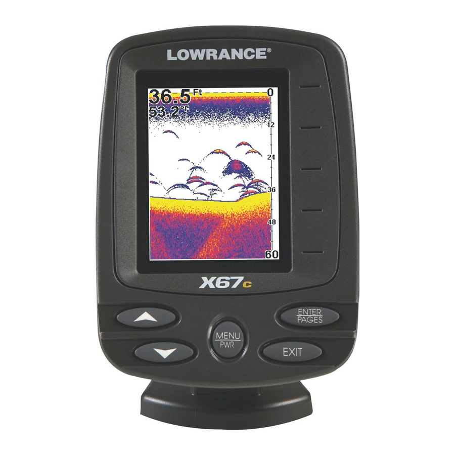
The unit sounds a tone when you press any key. This tells you the unit has accepted a command. Numbers in the photo correspond to key ex- planations below: Lowrance X67C Sonar, front view, showing screen and keyboard. 1. MENU/PWR (menu and power) This key appears in the manual text simply as turn the unit on and off.
-
Page 32: Memory
Menus Your sonar unit will work fine right out of the box with the factory de- fault settings. You only need to learn a few basic functions to enhance your viewing. We’ll discuss them briefly here, then talk about them and all the other commands in more detail in the next section, which begins on page 39.
-
Page 33
• Sonar Alarms command: turns alarms on or off and changes alarm thresholds. The fish alarm, used with Fish I.D., is the most popular use. It tells you when the sonar sees a fish. You can also set deep or shallow depth alarms. -
Page 34: Sonar Menu
. To clear the menu screen and return to the Page display, press EXIT Sonar Page Menu. Most of these functions are discussed in the Ad- vanced Section. Sonar Menu Commands The Sonar Menu contains commands for the major sonar features and…
-
Page 35
• Zoom command: controls the display size of sonar signal images. Pages The X67C has four major display options. They are the Full Sonar Chart, Split Zoom Sonar Chart, Digital Data and Flasher. You access the various display modes by pressing the key. -
Page 36
Fish arches around school of bait fish Structure Sonar Page, showing full sonar chart mode. Sonar chart display options (from left) full sonar chart and split zoom. Surface signal Bottom signal Surface clutter Depth scale In FasTrack, fish arches show as horizontal bars. -
Page 37
You can customize how the Sonar Page pictures and other data are dis- played in many ways. We’ll discuss all of those features and options in the Advanced Section, but to show you how easy the sonar unit is to op- erate, the following page contains a simplified, 10-step quick reference that will cover most fish finding situations. -
Page 38: Basic Sonar Quick Reference
The auto settings will track the bottom, displaying it in the lower por- tion of the screen. The full sonar chart will scroll from right to left, showing you what’s under the boat as you cruise across the water.
-
Page 39: Sonar Operations
As you can see from the quick reference on the previous page, basic operation is pretty easy, right out of the box. If you are a sonar novice, try operating the unit with the factory defaults until you get a feel for how it’s working.
-
Page 40
You can tell the car to run faster, but when you let off the gas the cruise control automatically keeps you from running slower than the minimum speed setting. In the sonar unit, auto mode will let you increase sensitiv- ity to 100 percent, but the unit will limit your minimum setting. This pre- vents you from turning sensitivity down too low to allow automatic bot- tom tracking. -
Page 41: Fish Symbols Vs. Full Sonar Chart
Fish I.D. fish symbol feature. Here’s why. Fish I.D. is an easier way for a sonar novice to recognize a fishy signal return when he sees it. However, locating fish by symbol only has some limitations.
-
Page 42: Other Free Training Aids
Aside from being just plain fun, this program can help you learn both basic and advanced operations without burning boat fuel! Lowrance is the first sonar manufacturer to provide this type of training tool for customers.
-
Page 43: Advanced Sonar Options & Other Features
Material in this section is arranged in alphabetical order. ASP (Advanced Signal Processing) The ASP feature is a noise rejection system built into the sonar unit that constantly evaluates the effects of boat speed, water conditions and interference. This automatic feature gives you the best display pos- sible under most conditions.
-
Page 44: Alarms
Alarms This unit has two different types of sonar alarms. The first is a Fish Alarm. It sounds when the Fish I.D. feature determines that an echo is a fish. The other alarm is the Depth Alarm, which has both a Shallow and a Deep setting.
-
Page 45: Fish Alarm
5. To turn off the alarm, press LARM NABLED To switch to a different depth setting, open the Sonar Alarms menu and repeat the instructions in step 3 above. Fish Alarm Use the fish alarm for a distinctive audible alarm when fish or other suspended objects are detected by the Fish I.D.…
-
Page 46: Calibrate Speed
Backlight Level Command, left, and Backlight Level control bar, right. The control bar appears automatically whenever you turn on the unit. Calibrate Speed The speed sensor can be calibrated to compensate for inaccuracies. Be- fore you change the setting, first calculate the percentage that the speed is off.
-
Page 47: Colorline
75 percent. When you are stationary and a fish swims through the sonar signal cone, the image appears on the screen as a long line instead of a fish arch. Reducing the chart speed may result in a shorter line that more closely resembles a regular fish return.
-
Page 48: Contrast
ColorLine is adjustable. Experiment with your unit to find the Color- Line setting that’s best for you. At left, Sonar Page menu with ColorLine command selected. At right, the ColorLine control bar. To adjust the ColorLine level: 1. From the Sonar Page, press 2.
-
Page 49: Depth Cursor
Depth box At left, Sonar Page menu with Depth Cursor command selected. At right, sonar chart with the depth cursor active. The line indicates the large fish is 40.52 feet deep. The cursor can be moved to any location on the screen, letting you pin- point the depth of a target.
-
Page 50: Depth Range — Automatic
You have complete control over the range when the unit is in the man- ual mode. There are 12 depth ranges, from 5 feet to 800 feet. To switch to Manual Depth Range: 1. First, turn off automatic depth range. From the Sonar Page, press |↓ to MENU EPTH 2.
-
Page 51: Depth Range — Upper And Lower Limits
This feature lets you «zoom in» the display in almost unlimited combinations. Nearly any segment of the water column, from the surface to the bottom can be shown. This enlarges the sonar targets to best suit your fishing needs and water conditions.
-
Page 52: Fastrack
«zoomed» with Upper and Lower Limits focusing on the portion of the water column from 10 feet to 20 feet deep. To turn off upper and lower limits: 1. From the Sonar Page, press FasTrack This feature automatically converts all echoes to short horizontal lines on the display’s far right side.
-
Page 53: Fish I.d. (Fish Symbols & Depths)
Does that mean Fish I.D. is broken? No — the feature is simply inter- preting sonar returns in a specific way to help take some of the work out of reading the screen. Remember: Fish I.D. is one of the many tools we provide so you can analyze your sonar returns for maximum fish finding information.
-
Page 54: Fishtrack
Fish I.D. symbols. Sonar Features menu with Fish I.D. Depths selected. When the check box to the left is checked, the feature is on. At right, Sonar Page show- ing Fish I.D. symbols and FishTrack depths turned on.
-
Page 55: Overlay Data
Overlay Data To change the digital data shown on top of the sonar page: 1. Press |↓ to MENU 2. Press ↓ or ↑ to select Data Type| Overlay Data command on the Sonar Menu, at left. Overlay Data Shown selection menu, right. In this example, we scrolled down the data list to highlight «Water Speed.»…
-
Page 56: Ping Speed & Hyperscroll
Depth, Water Temperature and the Water Speed of the boat. Ping Speed & HyperScroll Ping Speed controls the rate at which the transmitter and transducer broadcast sonar sound waves — pings — into the water. The unit has a VERLAY EXIT…
-
Page 57
When you turn HyperScroll off, you can return to your original sensitivity level. At left, Sonar Menu with Ping Speed command selected. Ping Speed Control Bar, right, at default setting. -
Page 58: Pop-Up Help
FasTrack bar graph display doubles in width at the right side of the screen. This allows you to better see the virtually instantaneous sonar returns, just as you would on a flasher sonar unit. For more informa- tion on FasTrack, see it’s entry in this section.
-
Page 59: Reset Options
Main Menu with Reset Options command selected. Reset Water Distance The sonar chart’s Digital Data display option includes a window that shows distance traveled, called Water Distance («W Distance»). This information is calculated from an optional water speed sensor. The Wa- ter Distance window can be reset to zero using the Reset Water Dis- tance command.
-
Page 60: Automatic Sensitivity
High sensitivity levels let you see this detail, but it can also clutter the screen with many undesired signals. Typically, the best sensitivity level shows a good solid bottom signal with Colorline and some surface clutter. Automatic Sensitivity The default sensitivity mode is automatic. The unit bases the sensitiv- ity level on water depth and conditions.
-
Page 61: Set Keel Offset
At left, Sonar Menu with Sensitivity command selected. At right, the To adjust sensitivity in manual mode: 1. First, turn off Auto Sensitivity: from the Sonar Page, press ENSITIVITY 2. Press ↑ to ENSITIVITY Press ↓ or ↑ to pick a different sensitivity setting. When it’s set at the…
-
Page 62: Set Language
On sailboats or other large vessels with deep drafts, the distance be- tween the transducer installation and the keel or lower engine unit can be several feet. In those cases, an inexact depth reading could result in grounding or striking underwater structure. The Keel Offset feature eliminates the need for the navigator to mentally calculate how much water is under his keel.
-
Page 63: Software Version Information
Software Version Information From time to time, Lowrance updates the operating system software in some of its products. These software upgrades are usually offered to customers as free downloads from our web site, www.lowrance.com.
-
Page 64: Sonar Page & Sonar Chart Display Options
Sonar Page & Sonar Chart Display Options The X67C offers four chart display options. To cycle through them, press to clear any menus, then press repeatedly until the de- EXIT sired mode appears. Full Sonar Chart This is the default mode used when the unit is turned on for the first time or when it’s reset to the factory defaults.
-
Page 65: Digital Data/Chart
Split Zoom Sonar Chart. Image at left shows the left window zoomed to 2X. The right image shows the left window zoomed to 4X. The depth overlay data is set to the default large text size; the water temperature is set to the medium text size.
-
Page 66: Flasher
Stop Chart If you are running multiple units on a boat, there are times when you may want to turn off the sonar. This command turns off the sonar and stops the chart from scrolling. Sonar restarts automatically each time you turn on your unit.
-
Page 67: Surface Clarity
Sonar Menu with Stop Chart command selected. The box is unchecked, indicating that the chart is scrolling across the screen. Surface Clarity The markings extending downward from the zero line on the chart are called «surface clutter.» These markings are caused by wave action, boat wakes, temperature inversion and more.
-
Page 68: Transparency
A low transparency will usually make menu text easier to read, at the cost of watching your sonar returns. Experiment with this feature until you find the right level of transpar- ency for your eyes.
-
Page 69: Zoom & Zoom Bar
Press |↓ to MENU MENU Main Menu, left, Units of Measure Menu, right. To set Units of Measure: Press ↓ to the desired units, then press After all the options are set as desired, press page display. Upper and Lower Limits See the entry in this section for Depth Range — Upper and Lower Limits Volume This command adjusts the speaker volume, which controls the sound…
-
Page 70: Zoom Pan
At left, Sonar Page, normal view. Center, same view zoomed to 2X. Tip: From the Sonar Menu, you can go directly to the Zoom Level com- mand with one keystroke. Instead of pressing the down arrow (↓) to reach the command, press the up arrow (↑) instead. This will take you from «Sensitivity»…
-
Page 71
Notes… -
Page 72: Troubleshooting
Unit freezes, locks up, or operates erratically: 1. Electrical noise from the boat’s motor, trolling motor, or an accessory may be interfering with the sonar unit. Rerouting the power and trans- ducer cables away from other electrical wiring on the boat may help.
-
Page 73
1. The transducer may be in turbulent water. It must be mounted in a smooth flow of water in order for the sonar to work at all boat speeds. Air bubbles in the water disrupt the sonar signals, interfering with its ability to find the bottom or other targets. -
Page 74
For example, turn on the bilge pump and view the sonar display for noise. If no noise is present, turn the pump off, then turn on the VHF radio and transmit. -
Page 75
Notes… -
Page 76
Notes… -
Page 77: Warranty And Service Information
LOWRANCE ELECTRONICS FULL ONE-YEAR WARRANTY «We,» «our,» or «us» refers to LOWRANCE ELECTRONICS, INC., the manufacturer of this product. «You» or «your» refers to the first person who purchases this product as a consumer item for personal, family or household use.
-
Page 78: How To Obtain Service
…in the USA: We back your investment in quality products with quick, expert service and genuine Lowrance parts. If you’re in the United States and you have technical, return or repair questions, please contact the Factory Customer Service Department. Before any product can be returned, you must call customer service to determine if a return is necessary.
-
Page 79
Accessory Ordering Information for all countries To order Lowrance GPS accessories such as computer cables or MMC cards, please contact: 1) Your local marine dealer or consumer electronics store. Most quality dealers that handle marine electronic equipment or other consumer electronics should be able to assist you with these items. -
Page 80
Visit our web site: Lowrance Pub. 988-0151-062 © Copyright 2003 All Rights Reserved Printed in USA 041603 Lowrance Electronics, Inc.
В представленном списке руководства для конкретной модели Эхолота — Lowrance X67C. Вы можете скачать инструкции к себе на компьютер или просмотреть онлайн на страницах сайта бесплатно или распечатать.
В случае если инструкция на русском не полная или нужна дополнительная информация по этому устройству, если вам нужны
дополнительные файлы: драйвера, дополнительное руководство пользователя (производители зачастую для каждого
продукта делают несколько различных документов технической помощи и руководств), свежая версия прошивки, то
вы можете задать вопрос администраторам или всем пользователям сайта, все постараются оперативно отреагировать
на ваш запрос и как можно быстрее помочь. Ваше устройство имеет характеристики:Тип: эхолот, Расположение корпуса: стационарное, Трансдьюсер: в комплекте, Крепление трансдьюсера: универсальное, Корпус: влагозащищенный, Питание: от сети 12В, полные характеристики смотрите в следующей вкладке.
Для многих товаров, для работы с Lowrance X67C могут понадобиться различные дополнительные файлы: драйвера, патчи, обновления, программы установки. Вы можете скачать онлайн эти файлы для конкретнй модели Lowrance X67C или добавить свои для бесплатного скачивания другим посетителями.
Если вы не нашли файлов и документов для этой модели то можете посмотреть интсрукции для похожих товаров и моделей, так как они зачастую отличаются небольшим изменениями и взаимодополняемы.
Обязательно напишите несколько слов о преобретенном вами товаре, чтобы каждый мог ознакомиться с вашим отзывом или вопросом. Проявляйте активность что как можно бльше людей смогли узнать мнение настоящих людей которые уже пользовались Lowrance X67C.

Все прикольно но не могу до конца розобраться
нормально
Хочу понять как работает
Даниил
2018-07-05 21:01:20
Не могу разобраться
Богдан
2018-08-19 00:33:05
Нужна инструкция
Валентин
2018-08-19 18:28:55
Он очень хорош
Ляззат
2018-08-27 15:32:15
не знаю как пользоваться
купил дешево
супер эхолот
Антон
2019-02-27 16:47:20
все сцпер
Антон
2019-02-27 16:50:57
супер
Хорошо!
Андрей
2019-10-27 16:55:00
Все супер
Владимир
2020-02-09 21:43:35
Необходимо иметь инструкцию на русском языке, чтобы до конца разобраться с его функциями. Прибор хороший.
Владимир
2020-02-09 21:46:19
Нужна инструкция, чтобы разобраться со всеми функциями. Работе хорошо.
Владимир
2020-02-09 21:47:51
Нужна инструкция, чтобы разобраться со всеми функциями. Работе хорошо.
марина
2020-03-17 15:58:43
нет инструкции на русском языке
Не могу настроить на сома.
Не могу настроить на сома.
Алекс
2020-09-17 20:31:49
Класний апарат
Хочу розібратися
Евген
2020-09-24 01:17:09
температуру не показывает(
Евген
2020-09-24 01:23:11
температуру не показывает
Основные и самые важные характеристики модели собраны из надежных источников и по характеристикам можно найти похожие модели.
| Конструкция | |
| Тип | эхолот |
| Расположение корпуса | стационарное |
| Трансдьюсер | в комплекте |
| Крепление трансдьюсера | универсальное |
| Корпус | влагозащищенный |
| Питание | от сети 12В |
| Рабочая температура | -20 — 75 ?C |
| Экран | |
| Тип экрана | цветной |
| Количество цветов/градаций экрана | 256 |
| Диагональ экрана | 3.5″ |
| Разрешение экрана | 240×320 пикс. |
| Подсветка экрана | есть |
| Трансдьюсер | |
| Количество лучей | 1 |
| Макс. глубина сканирования в пресной воде | 183 м |
| Выходная мощность, пиковая | 800 Вт |
| Выходная мощность, RMS | 100 Вт |
| Функции и особенности | |
| Датчик температуры | встроенный |
| Датчик скорости | опциональный |
| Звуковая сигнализация | есть |
| Отображение структуры дна | есть |
| Габариты (ШхВхГ) | 108x147x64 мм |
Здесь представлен список самых частых и распространенных поломок и неисправностей у Эхолотов. Если у вас такая поломка то вам повезло, это типовая неисправность для Lowrance X67C и вы можете задать вопрос о том как ее устранить и вам быстро ответят или же прочитайте в вопросах и ответах ниже.
| Название поломки | Описание поломки | Действие |
|---|---|---|
| Эхолот Не Видит Рыбу | ||
| Не Адекватно Показывает Рельеф Дна | ||
| Не Адекватно Показывает Рельеф Глубину | ||
| Не Включается | ||
| Не Включается Эхолот | Соединяю Провода Он Не Включается,В Прошлом Году Прекрасно Работал | |
| На Экране Очень Низкая Яркость, Звук Есть. | Изо То Появляется Чуть-Чуть, То Пропадает. | |
| Нет Сигнала Глубины С Датчика | Нет Индикации Глубинв | |
| Lorance Elite-5Hdi | Не Могу Переустановить Дату Пишет 2056 Гю | |
| Не Работает1 Луч | ||
| Оборвалась Провода От Разъёма Датчика Внутри Корпуса | Красный, Зелёный, Синий. Какой Куда Подпаивать? | |
| Он Горит И Не Чего Не Показывает | Он Горит И Не Чего Не Показывает |
В нашей базе сейчас зарегестрированно 18 353 сервиса в 513 города России, Беларусии, Казахстана и Украины.
1
Pub. 988-0151-152
Addendum I
X67C IceMachine
Since the manual was written for the X67C, specialized features and ac-
cessories have been added to create the X67C IceMachine
, a portable
color ice fishing sonar. The IceMachine
package includes the X67C so-
nar unit and the PPP-15 portable power pack. The PPP-15 includes a
self-leveling ice fishing transducer, a rechargeable battery and a freeze-
resistant carry bag.
Each X67C unit contains a menu command that allows you to switch the
sonar in and out of IceMachine mode. If you purchased a regular X67C
package with the Skimmer
transom-mount transducer, you can buy the
PPP-15 separately. If you purchased an IceMachine package, you can
buy a Skimmer transducer separately with mounts for transom, trolling
motor or portable suction-cup installations.
These accessory combinations and the unit’s digital flashers and scrolling
chart display make the X67C the most versatile ice fishing sonar in its
class. Owning an X67C is like having two fish finders in one, because it’s
equally at home on a boat in summer or on the ice in winter.
The main manual, part number 988-0151-062, introduces you to the
X67C, and it covers general warm weather operations. Introductory ma-
terial is only discussed in the main manual. You should be familiar with
those basic functions before you head for the ice. A good place to start is
the Basic Sonar Operation section, beginning on page 27, or the one-page
Basic Sonar Quick Reference, on page 34.
This addendum covers the basic ice fishing functions and any other op-
erational changes that may have occurred since the manual was pub-
lished. In addition to the instructions found here, be sure to read the
PPP-15 instruction booklet, part number 988-0147-871. It will tell you
how to set up the ice fishing power pack and mount the X67C.
Topics discussed in this document include:
Introduction to IceMachine Mode
•
Your unit now has five pages that display sonar information.
IceMachine Mode Operation
•
Sensitivity
•
ColorLine
•
Battery gauge.
Краткое содержание страницы № 1
Pub. 988-0151-152
Addendum I
X67C IceMachine
Since the manual was written for the X67C, specialized features and ac-
cessories have been added to create the X67C IceMachine, a portable
color ice fishing sonar. The IceMachine package includes the X67C so-
nar unit and the PPP-15 portable power pack. The PPP-15 includes a
self-leveling ice fishing transducer, a rechargeable battery and a freeze-
resistant carry bag.
Each X67C unit contains a menu command that allows you to switch the
sonar in a
Краткое содержание страницы № 2
Sonar Signal Interpretation • Signal band movement means fish. • Signal band color and fish position. • Signal band thickness and fish size. Ice Flasher Options • Split Zoom display mode • Color Modes. Scouting Through the Ice • You can hunt for fish before you ever drill a hole by scanning through the ice. Introduction to IceMachine Mode Your unit has five pages that display sonar information. In addition to Full Sonar Chart, Split Zoom Sonar Chart, Digital Data and Flasher, there is the Ice Fl
Краткое содержание страницы № 3
The Split Zoom and Sonar Chart pages share the same settings. The chart pages, the Flasher and Ice Flasher pages each have their own independent controls for Sensitivity, ColorLine and sonar color mode. For example, if you make any Sensitivity changes to the sonar chart page, the sensitivity settings for the Flasher and Ice Flasher are unchanged. Each of these set- tings are saved when you turn the unit off, so you can keep your favorite settings for each operating mode. Remember, no matter wha
Краткое содержание страницы № 4
To enter the IceMachine mode: 1. From the Full Chart Sonar page, press ENT|ENT|ENT to switch to the normal Flasher page. 2. Press MENU|↓ to ICEMACHINE MODE|ENT|EXIT and the Ice Flasher ap- pears. (To leave IceMachine mode and return to normal operation, just repeat step 2.) Flasher Page Menu, with IceMachine Mode command highlighted but turned off (box not checked). The following figure shows the various components of the Ice Flasher page display. Bottom ColorLine shows hard bottom Surface sign
Краткое содержание страницы № 5
Sensitivity Sensitivity and Auto Sensitivity are described in detail in the manual on page 55. To adjust sensitivity on the Flasher or Ice Flasher page, simply press ↑ to increase sensitivity and press ↓ to decrease sensitivity. The changes are displayed on the horizontal Sensitivity Control Bar. The Echo Strength Color Scale also changes as you adjust sensitivity. Important: Setting Sensitivity for Ice Fishing The IceMachine’s basic operation is pretty easy, right out of the box. If you’re a so
Краткое содержание страницы № 6
2. The ColorLine Control Bar appears. Press ↓ to decrease ColorLine; press ↑ to increase ColorLine. 3. When it’s set at the desired level, press EXIT. ColorLine distinguishes between weak and strong sonar signals by «painting» them with different colors. You can adjust ColorLine to suit your personal viewing tastes. The left figure shows the default Color- Line setting. The center figure shows a lower ColorLine setting and at right, a higher setting. These black and white illustrations don’t
Краткое содержание страницы № 7
Battery charge indicator This battery gauge is solid green, indicating a full charge. Sonar Signal Interpretation When you monitor your flasher screen for signs of fish, there are three signal band characteristics to watch for: movement, color and thickness. Signal band movement In a stationary setting like ice fishing, the bottom, structure and cover will show on the flasher screen as stationary bands of color. Signals between the surface and the bottom that come and go or move up and down (eve
Краткое содержание страницы № 8
Signal band thickness Simply put, smaller fish return smaller echoes that result in thinner and fainter signal bands. A thin signal can also indicate a fish located toward the outer edge of the signal cone. As fish size increases, the ech- oes grow stronger and the signal band grows wider. Signal width also increases as a fish approaches the center of the sonar cone. Ice Flasher Options Split Zoom Display Mode When ice fishing season arrives, you’re often searching for fish that are hugging the
Краткое содержание страницы № 9
The following figure show the bottom target separation possible using the flasher’s Split Zoom. Fish signal 1 zoomed Normal range side Bottom zoom side Fish signal 2 zoomed, Depth range about 3.5 60 feet feet above the bottom. This scale shows 6 feet above the bottom Fish signal 1 Fish signal 2 Bottom ColorLine Bottom ColorLine Notice the bottom target separation with Split Zoom mode. Color Modes Sonar Color Mode is described in detail in the manual on page 59. The additional ice fishing feature
Краткое содержание страницы № 10
3. Press ↑ or ↓ to Mode Name|ENT. 4. Press EXIT|EXIT to return to the flasher page. At left, Ice Flasher menu with Flasher Options selected. Center, Flasher Options menu with Flasher Color Mode selected. At right, Nightview color option is selected. Scouting Through the Ice Since the 1960s, Lowrance flasher sonars have helped anglers hunt fish beneath the ice without drilling holes. That’s because your IceMachine works as well through ice as it does through water! This technique works best
Краткое содержание страницы № 11
Notes 11
Краткое содержание страницы № 12
This addendum contains information that has changed or was unavailable when the manual was printed. This addendum supplements the manual X67C, part number 988-0151-062. It also serves as a companion to instructions for the PPP- 15 Portable Power Pack for ice fishing, part number 988-0147-871 Pub. 988-0151-152 © Copyright 2003 All Rights Reserved Printed in USA 111303 Lowrance Electronics, Inc. 12