1
RU
SSIAN
РУКОВОДСТВО ПО ЭКСПЛУАТАЦИИ
ДВОЙНАЯ ИЭОПЯЦИЯ
ПРЕДУПРЕЖДЕНИ:
В целях Вашей личной безопасности, ПРОЧТИТЕ и ОЗНАКОМЬТЕСЬ с данными
инструкциями перед использованием инструмента.
СОХРАНИТЕ
ДАННЫЕ
ИНСТРУКЦИИ
В
КАЧЕСТВЕ
СПРАВОЧНОГО
МАТЕРИАЛА.
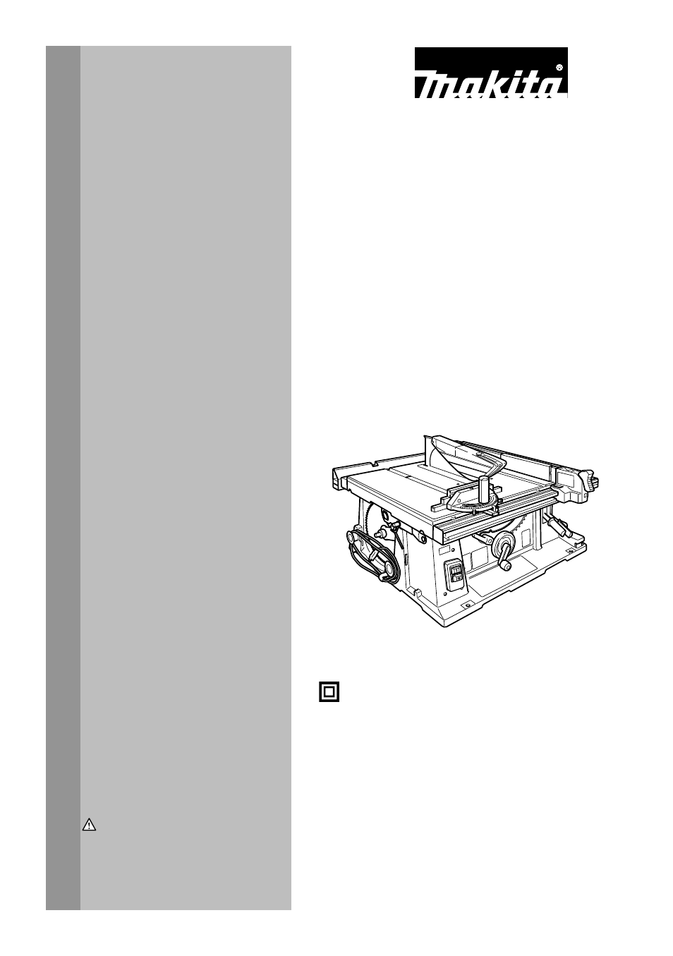
Отрезной станок со столом
2704
006133
RUSSIAN РУКОВОДСТВО ПО ЭКСПЛУАТАЦИИ Отрезной станок со столом 2704 006133 ДВОЙНАЯ ИЭОПЯЦИЯ ПРЕДУПРЕЖДЕНИ: В целях Вашей личной безопасности, ПРОЧТИТЕ и ОЗНАКОМЬТЕСЬ с данными инструкциями перед использованием инструмента. СОХРАНИТЕ ДАННЫЕ ИНСТРУКЦИИ В КАЧЕСТВЕ СПРАВОЧНОГО МАТЕРИАЛА. 1
РУССКИЙ ЯЗЫК ТЕХНИЧЕСКИЕ ХАРАКТЕРИСТИКИ 2704 Модель (для для европейских стран) (для остальных стран) Отверстие под шпиндель 30 мм 25 мм или 25,4 мм Диаметр полотна 260 мм 255 мм 90° 93 мм 91 мм 45° 64 мм Макс. мощность резки Число оборотов без нагрузки (мин.-1) 63 мм 4 800 Размер стола (Д х Ш)
000230 Томоясу Като Директор Ответственный производитель: Makita Corporation 3-11-8, Sumiyoshi-cho, Anjo, Aichi, JAPAN (ЯПОНИЯ) Уполномоченный представитель в Европе: Makita International Europe Ltd. Michigan Drive, Tongwell, Milton Keynes, Bucks MK15 8JD, ENGLAND (ВЕЛИКОБРИТАНИЯ) 7. ENA001-2 8.
15. 16. 17. 18. 19. 20. 21. всегда должны быть сухими и чистыми и не должны быть измазаны маслом или смазкой. Отключайте электроинструмент. Если инструмент не используется, перед выполнением обслуживания, сменой принадлежностей, таких как лезвия, биты и ножи. Не оставляйте на инструменте ключи,
12. 13. 14. 15. 16. 17. 18. 19. 20. 21. 22. 23. шпиндель, фланцы (особенно установочную поверхность) и шестигранную гайку. Ненадлежащая установка может вызвать вибрации/биения или соскальзывание полотна. Используйте ограждение полотна пилы и расклинивающий нож при выполнении любой операции, когда
31. 32. 33. 34. 35. УСТАНОВКА ПЕРЕД началом пиления выбейте всетвердые выпадающие сучки из распиливаемой детали. Аккуратно обращайтесь со шнуром питания. Никогда не дергайте за шнур для выключения вилки из розетки. Располагайте шнур на расстоянии от источников тепла, масла, воды и острых краев.
Хранение принадлежностей 1 Примечание: • При резке тонких материалов настройте небольшую глубину, чтобы получить более чистый разрез. 1. Измеритель угла резки Регулировка угла скоса 1 2 006152 1. Направляющая планка 1. Рычаг блокировки 2. Стрелочный указатель 3. Маховик 3 006155 Ослабьте рычаг
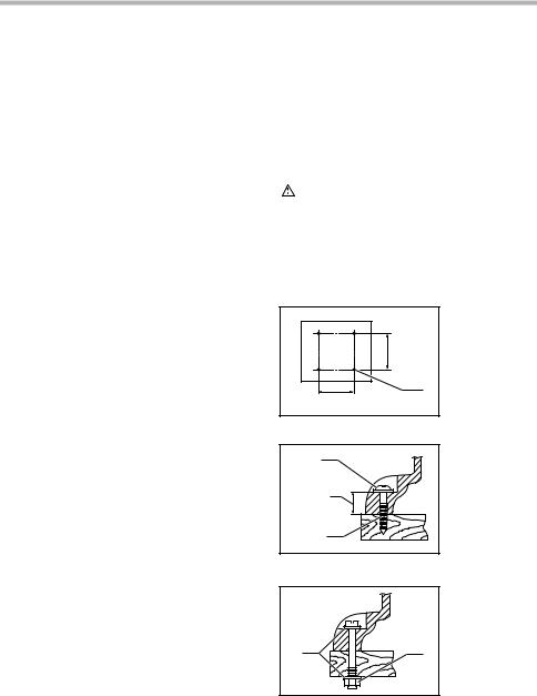
Установите угольник на стол и убедитесь в том, что угол наклона диска относительно поверхности стола составляет 90° или 45°. Если диск расположен под углом, показанным на Рис. А, поверните регулировочные винты по часовой стрелке; если диск расположен под углом, показанным на Рис. В, поверните
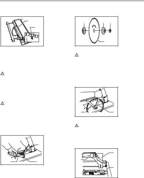
МОНТАЖ 1. Пластина со шкалой 2. Винт 1 ПРЕДУПРЕЖДЕНИ: Перед проведением каких-либо работ с инструментом всегда проверяйте, что инструмент выключен, а шнур питания вынут из розетки. Инструмент поставляется с завода без установленных на нем дисковой пилы и ограждения пилы. Выполняйте их установку в
шпиндель так, чтобы в передней части стола зубцы диска были направлены вниз. Всегда устанавливайте шестигранную гайку утопленной часть к внешнему фланцу. 1 2 4 • 1. Внутренний фланец 2. Кольцо 3. Пильное лезвие 4. Наружный фланец 5. Шестигранная гайка 5 3 ПРЕДУПРЕЖДЕНИ: Будьте осторожны, удерживая
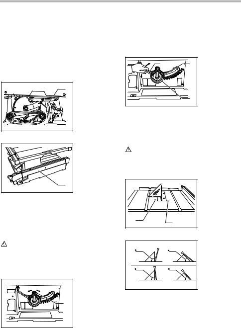
1 2 Между расклинивающим ножом и зубцами диска должен быть зазор порядка 4-5 мм. Отрегулируйте расклинивающий нож соответствующим образом и хорошо затяните болты с шестигранными головками (А). Вставьте вкладыш в стол и перед началом резки проверьте работоспособность ограждения диска. 1. Ограждение
Если направляющую планку невозможно надежно закрепить, отрегулируйте ее в соответствии со следующей процедурой. (1) Установите направляющую планку на столе, и затем поверните ручку на пол-оборота (перемещаемое положение). Затягивайте винт (А) до тех пор, пока направляющая планка не будет неподвижно
Всегда пользуйтесь подручными средствами, такими как нажимные палки и брусья, при резке небольших или узких деталей, а также тогда, когда головку для выборки пазов не видно. • 1. Указатель 2. Винты 1 2 Подручные средства Подручными средствами являются нажимные палки, нажимные брусья или
Деревянная облицовка (направляющей планки) 1 3. 1. Шурупы № 10 (с длиной, достаточной для вкручивания наполовину толщины облицовки) Включите инструмент, и осторожно подайте обрабатываемую деталь к диску вдоль направляющей планки. (1) Если ширина разреза составляет 150 мм и более, будьте осторожны
Упор-ограничитель измерителя угла резки продолжайте подавать деталь при помощи нажимного бруса, расположенного на верхней части вспомогательной планки. 1 1. Круглая ручка 2. Малая пластина 3. Винт упор-ограничителя 3 1. Нажимной брусок 2. Вспомогательная планка 2 1 006225 2 Измеритель угла резки
Для предотвращения качания длинной доски, установите на измеритель угла резки вспомогательную направляющую доску. Закрепите ее болтами/гайками, просверлив отверстия, но при этом крепежные детали не должны выступать на поверхности доски. Рычаги фиксации вала вспомогательного стола (R) Подвижная
ПРИНАДЛЕЖНОСТИ ПРЕДУПРЕЖДЕНИ: Эти принадлежности или насадки рекомендуется использовать вместе с Вашим инструментом Makita, описанным в данном руководстве. Использование каких-либо других принадлежностей или насадок может представлять опасность получения травм. Используйте принадлежность или
18
19
Makita Corporation Anjo, Aichi, Japan 884599C265 20
(скачивание инструкции бесплатно)
Формат файла: PDF
Доступность: Бесплатно как и все руководства на сайте. Без регистрации и SMS.
Дополнительно: Чтение инструкции онлайн

1
RU
SSIAN
РУКОВОДСТВО
ПО
ЭКСПЛУАТАЦИИ
ДВОЙНАЯ
ИЭОПЯЦИЯ
ПРЕДУПРЕЖДЕНИ
:
В
целях
Вашей
личной
безопасности
,
ПРОЧТИТЕ
и
ОЗНАКОМЬТЕСЬ
с
данными
инструкциями
перед
использованием
инструмента
.
СОХРАНИТЕ
ДАННЫЕ
ИНСТРУКЦИИ
В
КАЧЕСТВЕ
СПРАВОЧНОГО
МАТЕРИАЛА
.
Отрезной
станок
со
столом
2704
006133
Страница:
(1 из 20)
навигация

1

2

3

4

5

6

7

8

9

10

11

12

13

14

15

16

17

18

19

20
Оглавление инструкции
- Страница 1 из 21
RUSSIAN РУКОВОДСТВО ПО ЭКСПЛУАТАЦИИ Отрезной станок со столом 2704 006133 ДВОЙНАЯ ИЭОПЯЦИЯ ПРЕДУПРЕЖДЕНИ: В целях Вашей личной безопасности, ПРОЧТИТЕ и ОЗНАКОМЬТЕСЬ с данными инструкциями перед использованием инструмента. СОХРАНИТЕ ДАННЫЕ ИНСТРУКЦИИ В КАЧЕСТВЕ СПРАВОЧНОГО МАТЕРИАЛА. 1 - Страница 2 из 21
РУССКИЙ ЯЗЫК ТЕХНИЧЕСКИЕ ХАРАКТЕРИСТИКИ 2704 Модель (для для европейских стран) (для остальных стран) Отверстие под шпиндель 30 мм 25 мм или 25,4 мм Диаметр полотна 260 мм 255 мм 90° 93 мм 91 мм 45° 64 мм Макс. мощность резки Число оборотов без нагрузки (мин.-1) 63 мм 4 800 Размер стола (Д х Ш) - Страница 3 из 21
000230 Томоясу Като Директор Ответственный производитель: Makita Corporation 3-11-8, Sumiyoshi-cho, Anjo, Aichi, JAPAN (ЯПОНИЯ) Уполномоченный представитель в Европе: Makita International Europe Ltd. Michigan Drive, Tongwell, Milton Keynes, Bucks MK15 8JD, ENGLAND (ВЕЛИКОБРИТАНИЯ) 7. ENA001-2 8. - Страница 4 из 21
15. 16. 17. 18. 19. 20. 21. всегда должны быть сухими и чистыми и не должны быть измазаны маслом или смазкой. Отключайте электроинструмент. Если инструмент не используется, перед выполнением обслуживания, сменой принадлежностей, таких как лезвия, биты и ножи. Не оставляйте на инструменте ключи, - Страница 5 из 21
12. 13. 14. 15. 16. 17. 18. 19. 20. 21. 22. 23. шпиндель, фланцы (особенно установочную поверхность) и шестигранную гайку. Ненадлежащая установка может вызвать вибрации/биения или соскальзывание полотна. Используйте ограждение полотна пилы и расклинивающий нож при выполнении любой операции, когда - Страница 6 из 21
31. 32. 33. 34. 35. УСТАНОВКА ПЕРЕД началом пиления выбейте всетвердые выпадающие сучки из распиливаемой детали. Аккуратно обращайтесь со шнуром питания. Никогда не дергайте за шнур для выключения вилки из розетки. Располагайте шнур на расстоянии от источников тепла, масла, воды и острых краев. - Страница 7 из 21
Хранение принадлежностей 1 Примечание: • При резке тонких материалов настройте небольшую глубину, чтобы получить более чистый разрез. 1. Измеритель угла резки Регулировка угла скоса 1 2 006152 1. Направляющая планка 1. Рычаг блокировки 2. Стрелочный указатель 3. Маховик 3 006155 Ослабьте рычаг - Страница 8 из 21
Установите угольник на стол и убедитесь в том, что угол наклона диска относительно поверхности стола составляет 90° или 45°. Если диск расположен под углом, показанным на Рис. А, поверните регулировочные винты по часовой стрелке; если диск расположен под углом, показанным на Рис. В, поверните - Страница 9 из 21
МОНТАЖ 1. Пластина со шкалой 2. Винт 1 ПРЕДУПРЕЖДЕНИ: Перед проведением каких-либо работ с инструментом всегда проверяйте, что инструмент выключен, а шнур питания вынут из розетки. Инструмент поставляется с завода без установленных на нем дисковой пилы и ограждения пилы. Выполняйте их установку в - Страница 10 из 21
шпиндель так, чтобы в передней части стола зубцы диска были направлены вниз. Всегда устанавливайте шестигранную гайку утопленной часть к внешнему фланцу. 1 2 4 • 1. Внутренний фланец 2. Кольцо 3. Пильное лезвие 4. Наружный фланец 5. Шестигранная гайка 5 3 ПРЕДУПРЕЖДЕНИ: Будьте осторожны, удерживая - Страница 11 из 21
1 2 Между расклинивающим ножом и зубцами диска должен быть зазор порядка 4-5 мм. Отрегулируйте расклинивающий нож соответствующим образом и хорошо затяните болты с шестигранными головками (А). Вставьте вкладыш в стол и перед началом резки проверьте работоспособность ограждения диска. 1. Ограждение - Страница 12 из 21
Если направляющую планку невозможно надежно закрепить, отрегулируйте ее в соответствии со следующей процедурой. (1) Установите направляющую планку на столе, и затем поверните ручку на пол-оборота (перемещаемое положение). Затягивайте винт (А) до тех пор, пока направляющая планка не будет неподвижно - Страница 13 из 21
Всегда пользуйтесь подручными средствами, такими как нажимные палки и брусья, при резке небольших или узких деталей, а также тогда, когда головку для выборки пазов не видно. • 1. Указатель 2. Винты 1 2 Подручные средства Подручными средствами являются нажимные палки, нажимные брусья или - Страница 14 из 21
Деревянная облицовка (направляющей планки) 1 3. 1. Шурупы № 10 (с длиной, достаточной для вкручивания наполовину толщины облицовки) Включите инструмент, и осторожно подайте обрабатываемую деталь к диску вдоль направляющей планки. (1) Если ширина разреза составляет 150 мм и более, будьте осторожны - Страница 15 из 21
Упор-ограничитель измерителя угла резки продолжайте подавать деталь при помощи нажимного бруса, расположенного на верхней части вспомогательной планки. 1 1. Круглая ручка 2. Малая пластина 3. Винт упор-ограничителя 3 1. Нажимной брусок 2. Вспомогательная планка 2 1 006225 2 Измеритель угла резки - Страница 16 из 21
Для предотвращения качания длинной доски, установите на измеритель угла резки вспомогательную направляющую доску. Закрепите ее болтами/гайками, просверлив отверстия, но при этом крепежные детали не должны выступать на поверхности доски. Рычаги фиксации вала вспомогательного стола (R) Подвижная - Страница 17 из 21
ПРИНАДЛЕЖНОСТИ ПРЕДУПРЕЖДЕНИ: Эти принадлежности или насадки рекомендуется использовать вместе с Вашим инструментом Makita, описанным в данном руководстве. Использование каких-либо других принадлежностей или насадок может представлять опасность получения травм. Используйте принадлежность или - Страница 18 из 21
18 - Страница 19 из 21
19 - Страница 20 из 21
Makita Corporation Anjo, Aichi, Japan 884599C265 20 - Страница 21 из 21
Инструкции и руководства похожие на MAKITA 2704
Другие инструкции и руководства из категории Электропила
© 2023 manuals-help.ru, Все права защищены
![]()
I N S T R U C T I O N M A N U A L
M A N U E L D ‘ I N S T R U C T I O N
M A N U A L D E I N S T R U C C I O N E S
Table Saw
Scie de table
Sierra de Banco
2704
006134
DOUBLE INSULATION DOUBLE ISOLATION
DOBLE AISLAMIENTO
 WARNING:
For your personal safety, READ and UNDERSTAND before using. SAVE THESE INSTRUCTIONS FOR FUTURE REFERENCE.
 AVERTISSEMENT:
Pour votre propre sécurité, prière de lire attentivement avant l’utilisation. GARDER CES INSTRUCTIONS POUR RÉFÉRENCE ULTÉRIEURE.
 ADVERTENCIA:
Para su seguridad personal, LEA DETENIDAMENTE este manual antes de usar la herramienta. GUARDE ESTAS INSTRUCCIONES PARA FUTURA REFERENCIA.

ENGLISH
SPECIFICATIONS
|
Model |
2704 |
||
|
Arbor hole |
5/8” |
||
|
Blade diameter |
255 mm (10”) |
||
|
Max. cutting capacities |
90° |
91 mm (3-9/16”) |
|
|
45° |
63 mm (2-1/2”) |
||
|
Maximum dado capacity |
21 mm (13/16”) |
||
|
No load speed (RPM) |
4,800/min. |
||
|
Table size (L x W) |
567 mm x (753 mm — 1,066 mm) |
||
|
22-1/4” x (29-5/8” — 42”) |
|||
|
Dimensions (L x W x H) with table not extended |
665 mm x 753 mm x 344 mm |
||
|
26-1/4” x 29-5/8” x 13-1/2” |
|||
|
Net weight |
28 kg (61.8 lbs) |
||
•Due to our continuing programme of research and development, the specifications herein are subject to change without notice.
•Note: Specifications may differ from country to country.
For Your Own Safety Read Instruction Manual Before Operating Tool Save it for future reference GENERAL SAFETY PRECAUTIONS
USA007-2
(For All Tools)
1.KNOW YOUR POWER TOOL. Read the owner’s manual carefully. Learn the tool’s applications and limitations, as well as the specific potential hazards peculiar to it.
2.KEEP GUARDS IN PLACE and in working order.
3.REMOVE ADJUSTING KEYS AND WRENCHES. Form habit of checking to see that keys and adjusting wrenches are removed from tool before turning it on.
4.KEEP WORK AREA CLEAN. Cluttered areas and benches invite accidents.
5.DON’T USE IN DANGEROUS ENVIRONMENT. Don’t use power tools in damp or wet locations, or expose them to rain. Keep work area well lighted. Don’t use tool in presence of flammable liquids or gases.
6.KEEP CHILDREN AWAY. All visitors should be kept safe distance from work area.
7.MAKE WORKSHOP KID PROOF with padlocks, master switches, or by removing starter keys.
8.DON’T FORCE TOOL. It will do the job better and safer at the rate for which it was designed.
9.USE RIGHT TOOL. Don’t force tool or attachment to do a job for which it was not designed.
10.WEAR PROPER APPAREL. Do not wear loose clothing, gloves, neckties, rings, bracelets, or other jewelry which may get caught in moving parts. Nonslip footwear is recommended. Wear protective hair covering to contain long hair.
11.ALWAYS USE SAFETY GLASSES. Also use face or dust mask if cutting operation is dusty. Everyday eyeglasses only have impact resistant lenses, they are NOT safety glasses.
12.SECURE WORK. Use clamps or a vise to hold work when practical. It’s safer than using your hand and it frees both hands to operate tool.
13.DON’T OVERREACH. Keep proper footing and balance at all times.
14.MAINTAIN TOOLS WITH CARE. Keep tools sharp and clean for best and safest performance. Follow instructions for lubricating and changing accessories.
15.DISCONNECT TOOLS before servicing; when changing accessories such as blades, bits, cutters, and the like.
16.REDUCE THE RISK OF UNINTENTIONAL STARTING. Make sure switch is in off position before plugging in.
17.USE RECOMMENDED ACCESSORIES. Consult the owner’s manual for recommended accessories. The use of improper accessories may cause risk of injury to persons.
2

18.NEVER STAND ON TOOL. Serious injury could occur if the tool is tipped or if the cutting tool is unintentionally contacted.
19.CHECK DAMAGED PARTS. Before further use of the tool, a guard or other part that is damaged should be carefully checked to determine that it will operate properly and perform its intended function — check for alignment of moving parts, binding of moving parts, breakage of parts, mounting, and any other conditions that may affect its operation. A guard or other part that is damaged should be properly repaired or replaced.
20.DIRECTION OF FEED. Feed work into a blade or cutter against the direction of rotation of the blade or cutter only.
21.NEVER LEAVE TOOL RUNNING UNATTENDED. TURN POWER OFF. Don’t leave tool until it comes to a complete stop.
22.REPLACEMENT PARTS. When servicing use only identical replacement parts.
23.POLARIZED PLUGS. To reduce the risk of electric shock, this equipment has a polarized plug
(one blade is wider than the other). This plug will fit in a polarized outlet only one way. If the plug does not fit fully in the outlet, reverse the plug. If it still does not fit, contact a qualified electrician to install the proper outlet. Do not change the plug in any way.
VOLTAGE WARNING: Before connecting the tool to a power source (receptacle, outlet, etc.) be sure the voltage supplied is the same as that specified on the nameplate of the tool. A power source with voltage greater than that specified for the tool can result in SERIOUS INJURY to the user – as well as damage to the tool. If in doubt, DO NOT PLUG IN THE TOOL. Using a power source with voltage less than the nameplate rating is harmful to the motor.
USE PROPER EXTENSION CORD. Make sure your extension cord is in good condition. When using an extension cord, be sure to use one heavy enough to carry the current your product will draw. An undersized cord will cause a drop in line voltage resulting in loss of power and overheating. Table 1 shows the correct size to use depending on cord length and nameplate ampere rating. If in doubt, use the next heavier gage. The smaller the gage number, the heavier the cord.
Table 1. Minimum gage for cord
|
Ampere Rating |
Volts |
Total length of cord in feet |
||||||
|
120 V |
25 ft. |
50 ft. |
100 ft. |
150 ft. |
||||
|
More Than |
Not More Than |
AWG |
||||||
|
0 |
6 |
18 |
16 |
16 |
14 |
|||
|
6 |
10 |
18 |
16 |
14 |
12 |
|||
|
10 |
12 |
16 |
16 |
14 |
12 |
|||
|
12 |
16 |
14 |
12 |
Not Recommended |
||||
ADDITIONAL SAFETY RULES
USB059-1
DO NOT let comfort or familiarity with product (gained from repeated use) replace strict adherence to table saw safety rules. If you use this tool unsafely or incorrectly, you can suffer serious personal injury.
1.Wear eye protection.
2.Don’t use the tool in presence of flammable liquids or gases.
3.NEVER use the tool with an abrasive cut-off wheel installed.
4.Check the blade carefully for cracks or damage before operation. Replace cracked or damaged blade immediately.
5.Clean the spindle, flanges (especially the installing surface) and hex nut before installing the
blade. Poor installation may cause vibration/ wobbling or slippage of the blade.
6.Use saw-blade guard and spreader for every operation for which it can be used, including all through sawing operations. Always assemble and install the blade guard following the step by step instructions out-lined in this manual. Through sawing operations are those in which the blade cuts completely through the workpiece as in ripping or cross cutting. NEVER use the tool with a faulty blade guard or secure the blade guard with a rope, string, etc. Any irregular operation of the blade guard should be corrected immediately.
7.Immediately reattach the guard and spreader after completing an operation which requires removal of the guard.
8.Do not cut metals such as nails and screws. Inspect for and remove all nails, screws and other foreign matter from the workpiece before operation.
3
9.Remove wrenches, cut-off pieces, etc. from the table before the switch is turned on.
10.NEVER wear gloves during operation.
11.Keep hands out of the line of the saw blade.
12.NEVER stand or permit anyone else to stand in line with the path of the saw blade.
13.Make sure the blade is not contacting the spreader or workpiece before the switch is turned on.
14.Before cutting an actual workpiece, let the tool run for a while. Watch for vibration or wobbling that could indicate poor installation or a poorly balanced blade.
15.NEVER make any adjustments while tool is running. Disconnect tool before making any adjustments.
24.Some material contains chemicals which may be toxic. Take caution to prevent dust inhalation and skin contact. Follow material supplier safety data.
25.The guard can be lifted during workpiece setup and for ease of cleaning. Always make sure that guard hood is down and flat against sawtable before plugging in the tool.
SAVE THESE INSTRUCTIONS
WARNING:
MISUSE or failure to follow the safety rules stated in this instruction manual may cause serious personal injury.
|
16. Use a push stick when required. Push sticks |
INSTALLATION |
||
|
MUST be used for ripping narrow workpieces to |
Positioning table saw |
||
|
keep your hands and fingers well away from the |
006224 |
||
|
blade. |
|||
|
1. Hole diameter 8 |
|||
|
17. Pay particular attention to instructions for reduc- |
|||
|
mm (5/16”) |
|||
|
ing risk of KICKBACK. KICKBACK is a sudden |
|||
|
reaction to a pinched, bound or misaligned saw |
620 mm |
||
|
blade. KICKBACK causes the ejection of the |
|||
|
(24-9/16″) |
|||
|
workpiece from the tool back towards the opera- |
|||
|
tor. KICKBACKS CAN LEAD TO SERIOUS PER- |
1 |
||
|
SONAL INJURY. Avoid KICKBACKS by keeping |
|||
|
the blade sharp, by keeping the rip fence parallel |
525 mm (20-5/8″) |
||
|
to the blade, by keeping the spreader, antikick- |
|||
|
back pawls and blade guard in place and operat- |
|||
|
ing properly, by not releasing the workpiece until |
006146 |
||
|
you have pushed it all the way past the blade, |
1 |
1. 6 mm (1/4”) Std. |
|
|
and by not ripping a workpiece that is twisted or |
washer |
||
|
warped or does not have a straight edge to guide |
2. No.10 wood |
||
|
along the fence. |
25 mm |
screw 40 mm |
|
|
18. Do not perform any operation freehand. Free- |
(1-1/2”) min. |
||
|
(1″) |
|||
|
hand means using your hands to support or |
length |
||
|
guide the workpiece, in lieu of a rip fence or |
|||
|
miter gauge. |
2 |
||
|
19. NEVER reach around or over saw blade. NEVER |
|||
|
reach for a workpiece until the saw blade has |
|||
|
completely stopped. |
006148 |
||
|
20. Avoid abrupt, fast feeding. Feed as slowly as |
1. 6 mm (1/4”) Std. |
||
|
possible when cutting hard workpieces. Do not |
washer |
||
|
bend or twist workpiece while feeding. If you |
2. 6 mm (1/4”) |
||
|
stall or jam the blade in the workpiece, turn the |
Mounting bolt & |
||
|
tool off immediately. Unplug the tool. Then clear |
1 |
Nut tighten |
|
|
the jam. |
2 |
securely |
21. NEVER remove cut-off pieces near the blade or touch the blade guard while the blade is running.
22.Knock out any loose knots from workpiece BEFORE beginning to cut.
23.Don’t abuse cord. Never yank cord to disconnect Locate the table saw in a well lit and level area where you from receptacle. Keep cord away from heat, oil, can maintain good footing and balance. It should be
|
water and sharp edges. |
installed in an area that leaves enough room to easily |
|
handle the size of your workpieces. The table saw should |
4
be secured with four screws or bolts to the work bench or table saw stand using the holes provided in the bottom of the table saw. When securing the table saw on the work bench, make sure that there is an opening in the top of the work bench the same size as the opening in the bottom of the table saw so the sawdust can drop through.
If during operation there is any tendency for the table saw to tip over, slide or move, the work bench or table saw stand should be secured to the floor.
1. Miter gauge
1. Rip fence
The miter gauge, blade and wrenches can be stored on the left side of the base and the rip fence can be stored at the right side of the base. The blade guard to be removed in dado cutting can be stored at the right hand rear.
FUNCTIONAL DESCRIPTION
CAUTION:
•Always be sure that the tool is switched off and unplugged before adjusting or checking function on the tool.
Adjusting the depth of cut
006154
1. Handle
1
The depth of cut may be adjusted by turning the handle. Turn the handle clockwise to raise the blade or counterclockwise to lower it.
NOTE:
•Use a shallow depth setting when cutting thin materials in order to obtain a cleaner cut.
Adjusting the bevel angle
1.Lock lever
2.Arrow pointer
3.Handwheel
Loosen the lock lever counterclockwise and turn the handwheel until the desired angle (0° — 45°) is obtained. The bevel angle is indicated by the arrow pointer.
After obtaining the desired angle, tighten the lock lever clockwise to secure the adjustment.
CAUTION:
•After adjusting the bevel angle, be sure to tighten the lock lever securely.
1.90°Adjusting screw
2.45°Adjusting screw
The tool is equipped with positive stops at 90° and 45° to the table surface. To check and adjust the positive stops, proceed as follows:
Move the handwheel as far as possible by turning it. Place a triangular rule on the table and check to see if the blade is at 90° or 45° to the table surface. If the blade is at an angle shown in Fig. A, turn the adjusting screws clockwise; if it is at an angle shown in Fig. B, turn the adjusting screws counterclockwise to adjust the positive stops.
5
After adjusting the positive stops, set the blade at 90° to the table surface. Then adjust the arrow pointer so that its right edge is aligned to the 0° graduation.
|
006158 |
|
|
1. Arrow pointer |
|
|
1 |
|
|
Switch action |
|
|
006217 |
|
|
1. Switch |
|
|
ON |
OFF |
1
CAUTION:
•Before plugging in the tool, always be sure that the tool is switched off.
To start the tool, raise the switch lever. To stop it, lower the switch lever.
The hinged switch lever plate can be locked by passing padlock through the hasp on the left hand side.
006216
1. Padlock
1
006150
1. Sub table (R)
 1
1
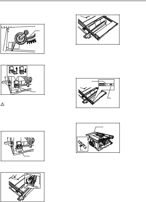
This tool is provided with the sub table (R) on the right side of the main table. To use the sub table (R), raise both levers on the front right side, pull out the table (R) fully and then lower the levers to secure it.
When using the sub table (R ), locate the scale plate on the sub table after loosening the screw on it with a screwdriver so that it becomes successive with the scale plate on the main table.
Sub table (back) and sub table (L)
(BOTH optional accessories)
1.Sub table (back)
2.Screw
Sub table (R)
006149
1. Lever
1
•When using the sub table (back ) during use of the rip fence, pull out the sub table (back) more than 50 mm so that it does not hit against the top end of the rip fence.
6
|
006136 |
||||||
|
1. |
Screw |
1. Inner flange |
||||
|
2. |
Sub table (L) |
1 |
2 |
4 |
2. |
Outer flange |
|
3. |
Saw blade |
|||||
|
4. |
Hex nut |
3
Sub table (back) can be installed at the back of the table to assure wider space. Sub table (L) can be installed on the left side of the table.
ASSEMBLY
CAUTION:
•Always be sure that the tool is switched off and unplugged before carrying out any work on the tool.
The tool is shipped from the factory with the saw blade and blade guard not in the installed condition. Assemble as follows:
Installing or removing saw blade
CAUTION:
•Always be sure that the tool is switched off and unplugged before installing or removing the blade.
•Use only the Makita socket wrench provided to install or remove the blade. Failure to do so may result in overtightening or insufficient tightening of the hex bolt. This could cause an injury.
1.Offset wrench
2.Hex nut
3.Wrench
Remove the table insert on the table. Hold the outer flange with the offset wrench and loosen the hex nut counterclockwise with the wrench. Then remove the outer flange.
Assemble the inner flange, blade, outer flange and hex nut onto the arbor, making sure that the teeth of the blade are pointing down at the front of the table. Always install the hex nut with its recessed side facing the outer flange.
CAUTION:
•Keep the flange surface clean of dirt or other adhering matter; it could cause blade slippage. Be sure that the blade is installed so that the teeth are aligned in the cutting (turning) direction.
To secure the blade in place, hold the outer flange with the offset wrench, then tighten the hex nut clockwise with the wrench. BE SURE TO TIGHTEN THE HEX NUT SECURELY.
•Be sure to hold the hex nut carefully with the wrench. If your grip should slip, the wrench may come off the hex nut, and your hand could strike the sharp blade edges.
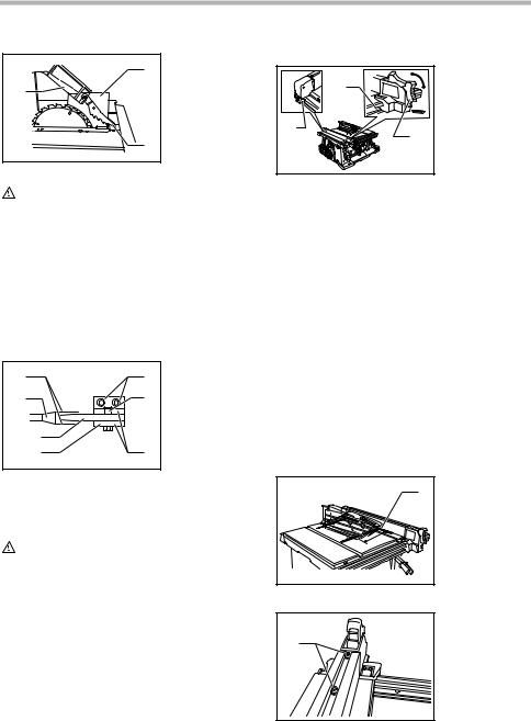
Installing blade guard
006140
2
1. Blade guard
2. Spreader
3. Blade guard
1 mounting portion (stay)
3
7
|
006139 |
Installing and adjusting rip fence |
|
2 |
1. |
Blade guard |
006159 |
|
|
2. |
Spreader |
|||
|
1 |
3. |
Antikickback |
3 |
|
|
pawl |
||||
|
1 |
||||
|
3 |
2 |
|||
1.Hook
2.Knob
3.Guide rail
CAUTION:
•Before installing the blade guard, adjust the depth of cut to its maximum elevation.
Remove the center cover and push the button inside the hole sideways. With the button so pushed, insert the blade guard into the blade guard mounting portion (stay).
The spreader installing location is factory-adjusted so that the blade and spreader will be in a straight line. However, if they are not in a straight line, loosen the hex bolts with hex wrench and adjust the blade guard mounting portion (stay) so that the spreader is aligned directly behind the blade. Then tighten the hex bolts to secure the stay.
|
006141 |
||||
|
1 |
5 |
1. |
These two |
|
|
clearances |
||||
|
2 |
7 |
should be equal |
||
|
2. |
Blade |
|||
|
3. |
Spreader |
|||
|
3 |
4. |
Pressure plate |
||
|
5. |
Hex bolts |
|||
|
4 |
6 |
|||
|
6. |
Blade guard |
|||
|
portion |
||||
|
7. |
Button |
CAUTION:
•If the blade and spreader are not aligned properly, a dangerous pinching condition may result during operation. Make sure they are properly aligned. You could suffer serious personal injury while using the tool without a properly aligned spreader.
•NEVER make any adjustments while tool is running. Disconnect the tool before making any adjustments.
1) Fit the hook on the tip of the rip fence into the far guide rail on the table or sub table (R) and install and push the rip fence forward so that the fence holder engages with the nearmost guide rail.
To slide the rip fence on the guide rail sideways, pivot the knob on the fence holder to the half way of its travel.
To secure the rip fence, pivot fully the knob on the fence holder.
2)To slide the rip fence on the guide rail sideways, return the knob on the fence holder fully without pulling the lever on the knob.
3)To remove it, pull the lever on the knob and pivot the knob fully forward while pulling the lever.
To check to be sure that the rip fence is parallel with the blade, secure the rip fence 2 — 3 mm (5/64” — 1/8” ) from the blade. Raise the blade up to maximum elevation. Mark one of the blade teeth with a crayon. Measure the distance (A) and (B) between the rip fence and blade. Take both measurements using the tooth marked with the crayon. These two measurements should be identical. If the rip fence is not parallel with the blade, proceed as follows:
8

1.Position the rip fence in the sliding position.
2.Loosen the two hex bolts on the rip fence with the hex wrench provided.
3.Adjust the rip fence until it becomes parallel with the blade.
4.Pivot down the knob on the rip fence toward the operator.
5.Tighten the two hex bolts on the rip fence.
•Be sure to adjust the rip fence so that it is parallel with the blade, or a dangerous kickback condition may occur.
Bring the rip fence up flush against the side of the blade. Make sure that the guideline on the fence holder points to the 0 graduation. If the guideline does not point to the 0 graduation, loosen the screw on the scale plate and adjust the scale plate.
|
006214 |
|
1 |
|
2 |
|
OPERATION |
|
CAUTION: |
•Always use “work helpers” such as push sticks and push blocks when there is a danger that your hands or fingers will come close to the blade.
•Always hold the workpiece firmly with the table and the rip fence or miter gauge. Do not bend or twist it while feeding. If the workpiece is bent or twisted, dangerous kickbacks may occur.
•NEVER withdraw the workpiece while the blade is running. If you must withdraw the workpiece before completing a cut, first switch the tool off while holding the workpiece firmly. Wait until the blade has come to a complete stop before withdrawing the workpiece. Failure to do so may cause dangerous kickbacks.
•NEVER remove cut-off material while the blade is running.
•NEVER place your hands or fingers in the path of the saw blade. Be especially careful with bevel cuts.
•Always secure the rip fence firmly, or dangerous kickbacks may occur.
•Always use “work helpers” such as push sticks and push blocks when cutting small or narrow workpieces, or when the dado head is hidden from view while cutting.
Work helpers
Push sticks, push blocks or auxiliary fence are types of “work helpers”. Use them to make safe, sure cuts without the need for the operator to contact the blade with any part of the body.
Push block
|
006219 |
||||
|
300mm(12″) |
||||
|
120mm |
130mm(5″) |
|||
|
(4-3/4″) |
||||
|
1 |
6mm |
50mm(2″) |
||
|
(1/4″) |
||||
|
2 |
||||
|
130mm |
300mm(12″) |
|||
|
(5″) |
||||
|
50mm |
||||
|
3 |
9.5mm |
(2″) |
||
|
4 |
100mm |
|||
|
(3/8″) |
||||
|
50mm |
(4″) |
|||
|
(2″) |
8mm(5/16″) |
1.Face/edge parallel
2.Handle
3.Wood screw
4.Glue together
Use a 19 mm (3/4”) piece of plywood.
Handle should be in center of plywood piece. Fasten with glue and wood screws as shown. Small piece 9.5 mm x 8 mm x 50 mm (3/8” x 5/16” x 2”) of wood must always be glued to plywood to keep the blade from dulling if the operator cuts into push block by mistake. (Never use nails in push block.)
Auxiliary fence
|
006211 |
||
|
9.5mm |
19mm |
120mm |
|
(3/4″) |
(4-3/4″) |
|
|
(3/8″) |
||
|
40mm |
||
|
(1-1/2″) |
||
|
1 |
460mm |
140mm |
|
(5-1/2″) |
||
|
(18″) |
||
Make auxiliary fence from 9.5 mm (3/8”) and 19 mm (3/ 4”) plywood pieces.
9
Wood facing (rip fence)
006165
1. No. 10 wood screws (long enough to pene-
trate halfway into facing)
 1
1
A wood facing should be used for operations when the blade comes close to the rip fence. Wood facing for the rip fence should be the same size as the rip fence. Make sure the bottom of facing is flush with the table surface.
Ripping
CAUTION:
•When ripping, remove the miter gauge from the table.
•When cutting long or large workpieces, always provide adequate support behind the table. DO NOT allow a long board to move or shift on the table. This will cause the blade to bind and increase the possibility of kickback and personal injury. The support should be at the same height as the table.
Before operating the table saw, check to be sure that the antikickback pawls operate properly. Turn the tool off and unplug it. Feed the workpiece under the blade guard and along both sides of the blade to simulate cutting. Try to withdraw the workpiece on each side by pulling it toward you. The antikickback pawls should grab the workpiece and prevent it from moving back toward the operator. Always keep the antikickback pawls sharp so they will operate properly. Keep them sharp by using a roundshaped file to maintain the original shape of the pawls.
1.Adjust the depth of cut a bit higher than the thickness of the workpiece.
2.Position the rip fence to the desired width of rip and lock in place by pivoting the grip. Before ripping, make sure the rear end of the rip fence is secured firmly. If it is not secured enough, follow the procedures in the section titled “Installing and adjusting rip fence”.
3.Turn the tool on and gently feed the workpiece into the blade along with the rip fence.
(1)When the width of rip is 150 mm (6”) and wider, carefully use your right hand to feed the workpiece. Use your left hand to hold the
workpiece in position against the rip fence.
006172
(2)When the width of rip is 65 mm — 150 mm (2- 1/2” — 6”) wide, use the push stick to feed the
workpiece.
006171
1. Push stick
1
|
(3) When the width of rip is narrower than 65 mm |
|
|
(2-1/2”), the push stick cannot be used |
|
|
because the push stick will strike the blade |
|
|
guard. Use the auxiliary fence and push |
|
|
block. Attach the auxiliary fence to the rip |
|
|
fence with two “C” clamps. |
|
|
006170 |
|
|
1 |
1. Auxiliary fence |
Feed the workpiece by hand until the end is about 25 mm (1”) from the front edge of the table. Continue to feed using the push block on the top of the auxiliary fence until the cut is complete.
10
![]()
1.Push block
2.Auxiliary fence
Cross cutting
CAUTION:
•When making a crosscut, remove the rip fence from the table.
•When cutting long or large workpieces, always provide adequate support to the sides of the table. The support should be at the same height as the table.
•Always keep hands away from path of blade.
Miter gauge
|
006166 |
||||
|
1 |
2 |
1. |
CROSS CUT- |
|
|
TING |
||||
|
2. |
MITERING |
|||
|
3. |
BEVEL CUT- |
|||
|
3 |
4 |
TING |
||
|
4. |
COMPOUND |
|||
|
MITERING |
||||
|
(ANGLES) |
Use the miter gauge for the 4 types of cutting shown in the figure.
CAUTION:
•Secure the knob on the miter gauge carefully.
•Avoid creep of workpiece and gauge by firm workholding arrangement, especially when cutting at an angle.
•NEVER hold or grasp the intended “cut-off” portion of the workpiece.
Miter gauge positive stop
1.Knob
2.Small plate
3.Screw for positive stop
Miter gauge is provided with positive stops at 90°, 45°right and left miter angles for quick setting of miter angles.
To set the miter angle, loosen the knob on the miter gauge.
Raise the small plate on the miter gauge for free setting. Turn the miter gauge to the desired miter angle. Return the small plate on the miter gauge to the original position and tighten the knob clockwise securely.
1.Groove
2.Miter gauge
3.Knob
Slide the miter gauge into the thick grooves in the table. Loosen the knob on the gauge and align to desired angle (0° to 60°). Bring stock flush up against fence and feed gently forward into the blade.
Auxiliary wood facing (miter gauge)
To prevent a long board from wobbling, fit the miter gauge with an auxiliary fence board. Fasten with bolts/ nuts after drilling holes, but fasteners must not protrude from the face board.
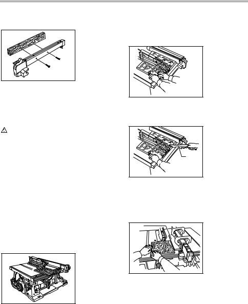
Carrying tool
006213
Carry the tool by holding the tool part shown in the figure.
11
MAINTENANCE
CAUTION:
•Always be sure that the tool is switched off and unplugged before attempting to perform inspection or maintenance.
Cleaning
Clean out sawdust and chips from time to time. Carefully clean the blade guard and moving parts inside the table saw.
Lubrication
To keep the table saw in tip-top running condition, and to assure maximum service life, oil or grease the moving parts and rotating parts from time to time.
Lubrication places:
•Threaded shaft to elevate the blade
•Hinge to rotate the frame
•Elevation guide shafts on motor
•Gear to elevate the blade
•Guide rails for the rip fence
•Shaft of the sub table (R) locking levers
•Sliding part of the sub table (R)
Replacing carbon brushes
001145
1. Limit mark
1
Remove and check the carbon brushes regularly. Replace when they wear down to the limit mark. Keep the carbon brushes clean and free to slip in the holders. Both carbon brushes should be replaced at the same time. Use only identical carbon brushes.
Use a screwdriver to remove the brush holder caps. To replace the carbon brushes, remove the blade guard and blade and then loosen the lock lever, tilt the saw head and secure it at 45° bevel angle. Carefully lay the tool on itself backward. Then loosen the brush holder cap. Remove the worn carbon brushes, insert the new ones and secure the brush holder caps.
After replacing brushes, plug in the tool and break in brushes by running tool with no load for about 10 minutes. Then check the tool while running and electric brake operation when releasing the switch trigger. If electric brake is not working well, ask your local Makita service center for repair.
|
006173 |
||
|
1 |
1. |
Brush holder |
|
2 |
cap |
|
|
2. |
Screwdriver |
To maintain product SAFETY and RELIABILITY, repairs, any other maintenance or adjustment should be performed by Makita Authorized or Factory Service Centers, always using Makita replacement parts.
ACCESSORIES
CAUTION:
•These accessories or attachments are recommended for use with your Makita tool specified in this manual. The use of any other accessories or attachments might present a risk of injury to persons. Only use accessory or attachment for its stated purpose.
If you need any assistance for more details regarding these accessories, ask your local Makita service center.
Dado head set (Part No. 191794-9)
1.Inside cutter
2.Outside cutter
A dado is cutting a rabbet or a wide groove into the workpiece. The dado head set consists of two outside cutters, five inside cutters and paper washers.
•Outside cutters: 6”diameter, 1/8” thick, 5/8”arbor hole, 2 pcs.
•Inside cutters: 6”diameter, 1/8”thick, 5/8”arbor hole,
4pcs.
•Inside cutter: 6”diameter, 1/16”thick, 5/8”arbor hole,
1pc.
•Paper washers: 5/8”arbor hole, 6 pcs.
Various combinations of these cutters are used to cut grooves from 1/8” to 13/16” for use in making joints, tenoning, grooving, etc.
12

Table insert (Part No. 317934-3)
006176
When cutting grooves, use this table insert instead of the standard table insert.
To install the dado head set, proceed as follows:
1.Turn the tool off and unplug it before installing.
2.Remove the blade guard with the spreader.
3.Install the dado head set with the teeth pointing down at the front of the table.
4.Use the chart below to select the proper cutters to obtain the various cutting widths.
|
006177 |
|||||||||
|
Spindle |
Inner |
Inner |
Outside |
1/8″ |
1/16″ |
Outside |
Outer |
Hex |
|
|
Inside |
|||||||||
|
flange flange |
Cutter |
Inside Cutter |
flange |
nut |
|||||
|
cutter |
|||||||||
|
cutter |
CUT
WIDTH
|
1/8″ |
|
|
1/4″ |
|
|
5/16″ |
|
|
3/8″ |
|
|
7/16″ |
|
|
1/2″ |
x2 |
|
9/16″ |
x2 |
|
5/8″ |
x3 |
|
11/16″ |
x3 |
|
3/4″ |
x4 |
|
13/16″ |
x4 |
CAUTION:
•For a 1/8” cut width, the outside cutter is assembled to the spindle in the same manner as the saw blade.
•The outer flange must be used for each cut width.
•The hex nut alone must not be used to secure the dado on to the spindle.
NOTE:
•When widths slightly greater than the above are required, fit the paper washers in between the inside and outside cutters to adjust the width.
5.Arrange the cutters so that the tips of the inside cutters are positioned at the gullets of the outside cutter. When more than one inside cutter is used, space the tips of the inside cutters equidistantly in
13
relation to one another. Poorly spaced cutters may cause vibration and noise.
1.Outside cutter
2.Inside cutter
3.Gullet
When installing two outside cutters without any inside cutter, be sure that the cutter tips do not face each other.
006179
6.While tightening the hex nut, be careful to maintain the even spacing between the tips of the inside cutters.
7.Rotate the dado head one turn by hand to make sure that it does not contact anything before operation.
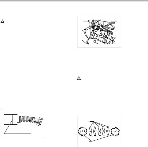
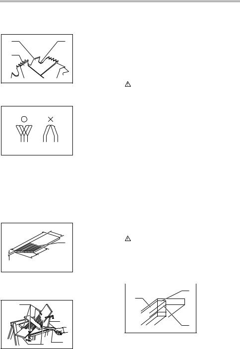
When dadoing, use featherboards. The diagram shown illustrates dimensions for making a typical featherboard. It should be made from a straight piece of wood that is free of knots or cracks.
|
006180 |
||
|
200 mm 1. Kerf should be |
||
|
600 mm |
(8″) |
about 6 mm |
|
(1/4”) apart |
||
|
(24″) |
||
|
1 |
||
|
130 mm (5″) |
||
|
115 mm |
||
|
19 mm(3/4″) |
(4-1/2″) |
Featherboards are used to keep the workpiece in contact with the rip fence and table as shown, and to stop kickbacks.
1.C clamps
2.Facing board
3.Push stick
4.Featherboard
To install featherboards, proceed as follows:
8.Turn the tool off and unplug it.
9.Add 8” high flat facing board to the rip fence, the full length of the rip fence.
10.Mount featherboards to the rip fence and table as shown, so that the leading edges of the featherboards will support the workpiece until the cut is completed, and the workpiece has been pushed completely past the cutter with a push stick.
11.Make sure featherboards are securely attached.
CAUTION:
•Only the Makita dado head set (Part No. 191794-9) should be used with Makita table saw Model 2704. Do not use dado combinations wider than 21 mm (13/16”).
•After dadoing, ALWAYS replace the blade guard with the spreader back in its original position on the table saw.
•NEVER attempt bevel cuts when dadoing.
•NEVER dado if there is vibration (flutter) or a strange noise.
•NEVER attempt dados in other than wood.
•Do not use the dado set for cut-offs.
•Feed work slowly, especially when cutting deep or wide grooves or dados. If a deep cut is needed, make several passes through the workpiece rather than one deep, wide cut. Fast or abrupt feeds can be dangerous.
•Use a push stick. When the dado head is hidden from view while cutting, your hands should never be on top of the stock.
•A very dangerous throwback can result if the wood becomes stuck and you try to remove it by pulling toward you. Always stop the tool and wait for dado head to come to a complete stop. Then simply withdraw the wood.
WARNING:
•Use extra caution when the guard assembly is removed for any non-through sawing operation such as dadoing, rabbeting or re-sawing. Replace guard immediately after non-through sawing is completed.
How to perform rabbeting
|
006183 |
|||
|
2 |
1. |
Rabbet |
|
|
2. |
Second cut |
||
|
1 |
|||
|
3. |
First cut |
3
14

1.Remove blade guard.
2.Attach auxiliary fence to rip fence for cuts that run the length of the stock. Facing should be as high as the workpiece is wide. Adjust fence and blade to desired dimensions.
3.First cut: Hold board flat on table as in ordinary ripping.
EN0006-1
MAKITA LIMITED ONE YEAR WARRANTY
Warranty Policy
Every Makita tool is thoroughly inspected and tested before leaving the factory. It is warranted to be free of defects from workmanship and materials for the period of ONE YEAR from the date of original purchase. Should
4.Second cut: Set workpiece on its edge. (Use feathany trouble develop during this one year period, return
erboards, push stick, push block and so on, using precautions, safety rules and guidelines for ripping or related work.)
5.For end-type rabbeting, if the workpiece is less than 10-1/2” wide, rest the wood flat on the table against the miter gauge (with wood facing). The rip fence should not be used.
6.After rabbeting is completed, immediately re-install the blade guard as before.
•Steel & Carbide-tipped saw blades
|
C00269 |
|||
|
Table/Miter saw |
For general purpose cuts for |
table and |
|
|
blades |
miter saws. |
||
|
Combination |
General purpose blade for |
fast |
and |
|
smooth rip, crosscuts and miters. |
|||
|
Fine cross cuts |
For sand-free cuts cleanly against |
the |
|
|
grain. |
|||
•Sub table ( L)
•Sub table ( back)
•Rip fence
•Miter gauge
•Offset wrench 13-22
•Wrench 19
•Hex wrench 5
•Auxiliary plate
the COMPLETE tool, freight prepaid, to one of Makita’s Factory or Authorized Service Centers. If inspection shows the trouble is caused by defective workmanship or material, Makita will repair (or at our option, replace) without charge.
This Warranty does not apply where:
•repairs have been made or attempted by others:
•repairs are required because of normal wear and tear:
•the tool has been abused, misused or improperly maintained:
•alterations have been made to the tool.
IN NO EVENT SHALL MAKITA BE LIABLE FOR ANY INDIRECT, INCIDENTAL OR CONSEQUENTIAL DAMAGES FROM THE SALE OR USE OF THE PRODUCT. THIS DISCLAIMER APPLIES BOTH DURING AND AFTER THE TERM OF THIS WARRANTY.
MAKITA DISCLAIMS LIABILITY FOR ANY IMPLIED WARRANTIES, INCLUDING IMPLIED WARRANTIES OF “MERCHANTABILITY” AND “FITNESS FOR A SPECIFIC PURPOSE,” AFTER THE ONE YEAR TERM OF THIS WARRANTY.
This Warranty gives you specific legal rights, and you may also have other rights which vary from state to state. Some states do not allow the exclusion or limitation of incidental or consequential damages, so the above limitation or exclusion may not apply to you. Some states do not allow limitation on how long an implied warranty lasts, so the above limitation may not apply to you.
15
 Loading…