инструкцияYamaha 703 (2015)

703
703-28199-P0
SIDE MOUNT REMOTE CONTROL INSTRUCTION
INSTRUCTIONS COMMANDE A DISTANCE
MONTAGE LATERAL
INSTRUCCIONES DEL CONTROL REMOTO DEL
AMORTIGUADOR LATERAL
サイドマウントリモートコントロール取扱説明書
Printed in Japan
Dec. 2014 !
(E, F, ES, J)
EN
FR
ES
JP
q
Read this manual carefully before operation.
q
Il convient de lire attentivement ce manuel avant l’utilisation.
q
Lea atentamente este manual antes del uso.
q
本書をよく読んでからお使いください。
Printed on recycled paper
Imprimé sur papier recyclé
Impreso en papel reciclado
再生紙を使用しています。
703-28199-P0_cover.indd 1 2014/12/02 15:57:28
Посмотреть инструкция для Yamaha 703 (2015) бесплатно. Руководство относится к категории подвесные лодочные моторы, 5 человек(а) дали ему среднюю оценку 7.9. Руководство доступно на следующих языках: английский. У вас есть вопрос о Yamaha 703 (2015) или вам нужна помощь? Задайте свой вопрос здесь
- CONTENTS
Главная
Не можете найти ответ на свой вопрос в руководстве? Вы можете найти ответ на свой вопрос ниже, в разделе часто задаваемых вопросов о Yamaha 703 (2015).
Не нашли свой вопрос? Задайте свой вопрос здесь
| Название | Русский | English |
|---|---|---|
| R-V703 OWNER’S MANUAL | — |
[623KB] |
| TP-6000 TP-4000 TP-5000 TP-7000 Series Owner’s Manual | — |
[358KB] |
@YAMAHA
703
@
SIDE MOUNT REMOTE CONTROL INSTRUCTION
INSTRUCTIONS COMMANDE
A
DISTA]’ffi
MONTAGE LATERAL
@
INSTRUCCIONES DEL CONTROL REMOTO DEL
AMORTIGUADOR LATERAL
@
ü,(
F»
ü:)
1.,
U
t-
1..=
)
hE-rlrflffi=HEn=
A
ReaO
this
manual carefully before operation.
A
ll convient de
tire
attentivement ce manuel avant I’utilisation.
A
tea
atentamente este manual antes del uso.
a
ä=ät
<
=ätueül5äjü€ur
<
riüur.
703-291
gg-Po

луха
капитан 1-го ранга
-
#51
zavitay сказал(а):
+100 старая модель
-
#52
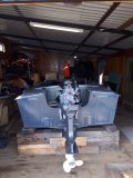
Всем привет. Только начинаю осваивать водный мир на Байкале. Собираю лодку Прогресс 2 с мотором ямаха 40 и 703 дистанцией. От машинки идет большой штекер и грядка контактов я так понял с плюсом, минусом и контактом на тахометр. А вот на карб нет тяг. Бывает электронный газ или у меня не комплект?

ETI
старшина 1ст.
-
#53
Всем привет. Только начинаю осваивать водный мир на Байкале. Собираю лодку Прогресс 2 с мотором ямаха 40 и 703 дистанцией. От машинки идет большой штекер и грядка контактов я так понял с плюсом, минусом и контактом на тахометр. А вот на карб нет тяг. Бывает электронный газ или у меня не комплект?
На газ и реверс в нижней части 703 машинки подсоединяются тяги в оболочках С-2
-
#54
Всем привет. Только начинаю осваивать водный мир на Байкале. Собираю лодку Прогресс 2 с мотором ямаха 40 и 703 дистанцией. От машинки идет большой штекер и грядка контактов я так понял с плюсом, минусом и контактом на тахометр. А вот на карб нет тяг. Бывает электронный газ или у меня не комплект?
Вот в кино всё показано, куда и что подсоединять.
-
#55
Вот в кино всё показано, куда и что подсоединять.
Спасибо) Еще вопрос по средствам чего вытягивая подсос на машинке он вытягивается на карбюраторе?)
-

209,6 КБ
Просмотры: 806
-
#56
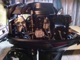
Спасибо) Еще вопрос по средствам чего вытягивая подсос на машинке он вытягивается на карбюраторе?)
Это не подсос. Это газ на холостых. Подсос на машинке управляется ключом, перед запуском ключ утопить внутрь(нажать на него), этим самым срабатывает электро-клапан подсоса, и можно запускать мотор. На фотке видно, под ручным стартером приблуда с катушкой и с проводами, это он.
-
183 КБ
Просмотры: 1 239
-
#57
Это не подсос. Это газ на холостых. Подсос на машинке управляется ключом, перед запуском ключ утопить внутрь(нажать на него), этим самым срабатывает электро-клапан подсоса, и можно запускать мотор. На фотке видно, под ручным стартером приблуда с катушкой и с проводами, это он.
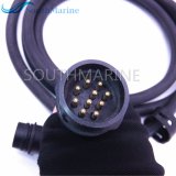
И еще прочитал что с машинки выходит пучек проводов, черный красный, зеленый и еще пара каких то) а на моей всего 3) черный, желтый и зеленый. что туда подключается и есть ли возможность подцепить тахометр от жигулей?)
луха
капитан 1-го ранга
-
#59
Минус, зажигание и сигнал тахометра. ИМХО жигулевский без доработки не будет работать….
-
#60
Минус, зажигание и сигнал тахометра. ИМХО жигулевский без доработки не будет работать….
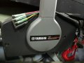
Добрый вечер, подскажите а что за три спаренных провода ещё выходят из 703й машинки??? Заранее благодарю!!!
луха
капитан 1-го ранга
-
#61
Добрый вечер, подскажите а что за три спаренных провода ещё выходят из 703й машинки??? Заранее благодарю!!!
Какие именно?
-
#62
Красный, серозеленый и сиреневый.
-
#63
Они идут именно спаренные…
Последнее редактирование: 30.07.2019
луха
капитан 1-го ранга
-
#64
Красный плюс, зеленый с синим подьем-опускание. Один провод на кнопку трим, выволы для подключения доп. Кнопки.
луха
капитан 1-го ранга
-
#66
Спасибо за вразумительный ответ. А на панели на указатель трима провода вести с мотора???
-
#67
Красный плюс, зеленый с синим подьем-опускание. Один провод на кнопку трим, выволы для подключения доп. Кнопки.
Или к этим проводам можно подключить указатель на панели приборов!!!
луха
капитан 1-го ранга
-
#68
Спасибо за вразумительный ответ. А на панели на указатель трима провода вести с мотора???
Да.
-
#69
Здравия всем!
Переделал ямаху 15-ку под дистанцию, но вот проблемка — чот я ни где не встретил чтоб кто то говорил про ответный разъём для 703-ей машинки? Не пойму как этот байонетный разъём подключают к мотору? В нете нашёл только удлинитель данного кабеля стоимостью 3000 руб. Жалко как то за такую сумму покупать и отрезать только нужный разъём. В видеороликах этот вопрос тоже ни кем не освещается. Короче подскажите может кто знает номенклатуру данного разъёма, как он собака обзывается, чтоб найти ответную часть.
Мне необходимо отсоединять этот кабель т.к. я снимаю двигатель при транспортировке.
-
#70
нужен вот такой
-
#71
И
И они бывают на 10 и 13 пинов. Последний под гидравлику.
-
#72
И они бывают на 10 и 13 пинов. Последний под гидравлику.
Мне нужен 10-пиновый.
3.
SAFETY FUNCTIONS
Depending on the
combination
of
the
remote control
box and engine, following function may not apply
some
models. Refer to
the Outboard motor
Owner’s
Manual for
further
information.
(1)
Warning buzzer
The buzzer will sound if the engine overheats,
the
engine
oil
pressure
drops (4-stroke engine) or
the
engine
oil tank nearly empties (2-stroke
engine)
which activated by
the sensor installed on the
en-
gine.
If the
warning buzzer sounds,
turn off the engine
and check
the cooling water inlet and engine oil
quantity-
Then, return
to
nearest
port
immedi-
ately at low speeds. Please
consult
your
Yamaha
dealer.
(2) Neutralswitch
The neutral switch prevents the engine from start-
ing
with in-gear position. When
the
remote control
lever is in forward
or
reverse,
the engine cannot
be
started
by
operating
the
main switch.
4.
REMOTE CONTROL BOX
POSITIONING AND REMOTE
CONTROL
CABLE
LENGTH
lncorrect selection or installation of a
remote
control box may
reeuE
in sudden and unexpect-
ed loss
of eonüol, thus resulting in
a
serious ac-
cident. Please consutt yourYamaha
dealer-
(1)
Remote
control box position
The remote control box should be set in
a
position
which
it does not obstruct the operations of the
re-
mote
control
lever and switches.
Make sure
there is
no obstruction on
the
path of the
remote control cables.
(2)
Remote
control cable length
Measure
the
distance
from the
«A»
point
(the center
of
the
remote control box)
io
the
«C»
point (the center
of
the
engine)
through the
«B»
point
(a
corner of
the
transom).
Add
1
m
(3
ft)
length
to
make
a
loop in the
motor-well.
Position
the
remote
control cables and check that
they
are
long enough. Connect
ihe
cables to
the
en-
gine and make
sure
they
do not
interfere
with
other
components when
the steering is fully turned
and
the engine
is
fulty
tilted
up.
Do
not bend the
33C
type (standard inner core)
remote eontro! cable
to the
400
mm (16 in) or
less in diameter, and the
33HPC
type (low-friction
inner core) remote control cable to the
300 mm
(12 in)
or less in diameter.
Bending
the cable sharper than
this
limit could
cause shorten
the !ife span of the cable
and
increase resistance
to the
movement
of the
re-
mote
control
lever.
1. Loop
INSTALLING THE REMOTE
CONTROL CABLES
Pinch the wire cover with your
fingers
and pull
it
out
to
remove.
5.
1)
1. Wire cover
2)
Remove
the two screws, and
remove the
panel
(loweO.
L
back
3)
-^/
1′
Back
panel
(lower)
Screw in
the
cable
joints about 11 mm (0.4
in)
over
ihe
ends
of the remote control
cables,
and
tighten
the
locknuts. Before installing the
cable joints, apply
the water-resistance
grease
(Yamaha Grease
A)
to the holes in the
cable
joints.
Машинка ямаха 703 выходят четыре провода куда что подключать?
-
#1
- Контактная информация
-
89875304391
Парни подскажите плиз мотор ямаха 4т 20лс
-

62.8 КБ
· Просмотры: 514
20190526_174309.jpg
Машинка ямаха 703 выходят четыре провода куда что подключать?
-
#2
Черный — минус
Желтый — плюс через ключ
Красный — плюс постоянный
Зеленый — сигнал для тахометра
Машинка ямаха 703 выходят четыре провода куда что подключать?
-
#3
Коллеги , день добрый.
Есть машинка аналог Я 703, коннектор 11 пин, и есть желание присоединить хотя бы кнопку страха к Тохе 18, подскажите каталожный номер разъема который устанавливается на моторах Ямаха.
Машинка ямаха 703 выходят четыре провода куда что подключать?
-
#4
Ребята помогите, отсоединил провода от машинки 703, протаскивал провода в гофру, все соединил по цветам, черный провод(-) присоединил к черному на замке зажигания, а черный с чеки (я так понимаю тоже минус) остался не у дел…. Куда его?)) Может я не увидел чего….


|


View a manual of the Yamaha 703 (2015) below. All manuals on ManualsCat.com can be viewed completely free of charge. By using the ‘Select a language’ button, you can choose the language of the manual you want to view.

MANUALSCAT | EN
Question & answers
Have a question about the Yamaha 703 (2015) but cannot find the answer in the user manual? Perhaps the users of ManualsCat.com can help you answer your question. By filling in the form below, your question will appear below the manual of the Yamaha 703 (2015). Please make sure that you describe your difficulty with the Yamaha 703 (2015) as precisely as you can. The more precies your question is, the higher the chances of quickly receiving an answer from another user. You will automatically be sent an e-mail to inform you when someone has reacted to your question.
Ask a question about the Yamaha 703 (2015)
Page: 1
703
703-28199-P0
SIDE MOUNT REMOTE CONTROL INSTRUCTION
INSTRUCTIONS COMMANDE A DISTANCE
MONTAGE LATERAL
INSTRUCCIONES DEL CONTROL REMOTO DEL
AMORTIGUADOR LATERAL
サイドマウントリモートコントロール取扱説明書
Printed in Japan
Dec. 2014 !
(E, F, ES, J)
EN
FR
ES
JP
q Read this manual carefully before operation.
q Il convient de lire attentivement ce manuel avant l’utilisation.
q Lea atentamente este manual antes del uso.
q 本書をよく読んでからお使いください。
Printed on recycled paper
Imprimé sur papier recyclé
Impreso en papel reciclado
再生紙を使用しています。
703-28199-P0_cover.indd 1 2014/12/02 15:57:28
Page: 2
CONTENTS
1. MAIN COMPONENTS……………………………………………………….2
2. OPERATION…………………………………………………………………….3
(1) Remote control lever……………………………………………………………….. 3
(2) Neutral interlock trigger.
…………………………………………………………… 3
(3) Neutral throttle lever.
……………………………………………………………….. 3
(4) Main switch……………………………………………………………………………. 3
(5) Choke switch.
…………………………………………………………………………. 3
(6) Engine shut-off cord (lanyard) and clip………………………………………. 4
(7) Engine stop button………………………………………………………………….. 4
(8) Power trim and tilt switch…………………………………………………………. 4
(9) Throttle friction adjuster…………………………………………………………… 4
3. Safety functions……………………………………………………….5
(1) Warning buzzer………………………………………………………………………. 5
(2) Neutral switch………………………………………………………………………… 5
4. REMOTE CONTROL BOX POSITIONING AND REMOTE
CONTROL CABLE LENGTH.
……………………………………………..5
(1) Remote control box position…………………………………………………….. 5
(2) Remote control cable length…………………………………………………….. 5
5. INSTALLING THE REMOTE CONTROL CABLES.
………………..5
6. CHANGE IN THE REMOTE CONTROL LEVER POSITION……7
7. CHANGE FROM THE PUSH-TO-OPEN THROTTLE TYPE
TO THE PULL-TO-OPEN THROTTLE TYPE…………………………8
8. THROTTLE OPENING ADJUSTMENT AT REVERSE.
…………10
9. REMOTE CONTROL BOX FOR TWIN-ENGINE………………….10
10.NOTE ON STORAGE.
………………………………………………………10
English
Français
Español
日本語
Page: 3
2
This remote control box has designed that both shift and throttle control can be actuated by operating the remote
control lever. For the correct operation and installation of the remote control box, please read this instructions care-
fully and thoroughly.
In this instructions particularly important information is distinguished in the following ways.
This is the safety alert symbol. It is used to alert you to potential personal injury hazards. Obey all safety mes-
sages that follow this symbol to avoid possible injury or death.
A WARNING indicates a hazardous situation which, if not avoided, could result in death or serious injury.
A NOTICE indicates special precautions that must be taken to avoid damage to the remote control box or
other property.
TIP
A TIP provides key information to make procedures easier or clearer.
Designs and specifications are subject to change without notice.
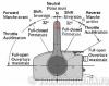
1. MAIN COMPONENTS
1
9
3
8
4
5
6 7
2
1. Grip
2. Neutral interlock trigger
3. Power trim and tilt switch*
4. Neutral throttle lever
5. Main switch/Choke switch*
6. Engine shut-off switch/Engine stop switch*
7. Wire harness (2, 7, or 10 pin)*
8. Throttle friction adjuster
9. Remote control lever
TIP
The mark (*) differs on the remote control specifications.
Page: 4
3
2. OPERATION
(1) Remote control lever
Moving the lever forward from the neutral position
engages forward gear. Pulling the lever back from
neutral engages reverse. The engine will continue to
run at idle until the lever is moved about 32° (a de-
tent can be felt). Moving the lever farther opens the
throttle, and the engine will begin to accelerate.
F R
1
2 3
4
4
5
5 6
6
F
N
R
1. Neutral “N”/Fully closed
2. Forward “F” (about 32°)
3. Reverse “R” (about 32°)
4. Shift
5. Throttle
6. Fully open
(2) Neutral interlock trigger
Keeps the remote control lever in the neutral posi-
tion. To shift in gear position, first pull the neutral
interlock trigger up and move the lever.
1
1. Neutral interlock trigger
(3) Neutral throttle lever
To open the throttle without shifting into either for-
ward or reverse, put the remote control lever in the
neutral position and lift the neutral throttle lever.
2
3
1
1. Neutral throttle lever
2. Fully open
3. Fully closed
TIP
The neutral throttle lever will operate only when the
remote control lever is in neutral. The remote control
lever will operate only when the neutral throttle lever
is in the closed position.
(4) Main switch
The main switch controls the ignition system; its op-
eration is described below.
OFF ON START
• “OFF” (off)
With the main switch in the “OFF” (off) position,
the engine stops. (The key can be removed.)
• “ON” (on)
With the main switch in the “ON” (on) position, the
accessory can be used. (The key cannot be re-
moved.)
• “START” (start)
With the main switch in the “START” (start) posi-
tion, the starter motor turns to start the engine.
When the key is released, it returns automatically
to the “ON” (on) position.
(5) Choke switch
To activate the choke system, press in the main
switch while the key is turned to the “ON” (on) or
“OFF” (off) position. The choke system will activate
and supply the rich fuel mixture required to start the
cold engine. (When the key is released, the choke
system will deactivate automatically.)
TIP
The choke switch functions, only with the engine
has the remote choke system.
Page: 5
4
(6) Engine shut-off cord (lanyard) and clip
The clip must be attached to the engine shut‑off
switch for the engine to run. The cord should be at-
tached to a secure place on the operator’s clothing,
or arm or leg. Should the operator fall overboard or
leave the helm, the cord will pull out the clip, stop-
ping ignition to the engine. This will prevent the boat
from running away under power.
• Attach the engine shut-off cord (lanyard) to a
secure place on your clothing, or your arm or
leg while operating.
• Do not attach the cord to clothing that could
tear loose. Do not route the cord where it
could become entangled, preventing it from
functioning.
• Avoid accidentally pulling the cord during nor-
mal operation. Loss of engine power means
the loss of most steering control. Also, without
engine power, the boat could slow rapidly. This
could cause people and objects in the boat to
be thrown forward.
1
2
3
1. Engine shut-off cord (lanyard)
2. Clip
3. Engine shut-off switch
(7) Engine stop button
The engine stop button (red) stops the engine when
the button is pushed.
(8) Power trim and tilt switch
The power trim and tilt system adjusts the outboard
motor angle in relation to the transom. Pushing the
switch “UP” (up) trims the outboard motor up, and
then tilts it up. Pushing the switch “DN” (down) tilts
the outboard motor down and trims it down. When
the switch is released, the outboard motor will stop
in its current position.
UP
DN
(9) Throttle friction adjuster
A friction device provides adjustable resistance to
movement of the remote control lever, and can be
set according to operator preference. To increase
resistance, turn the adjuster clockwise. To decrease
resistance, turn the adjuster counterclockwise.
Do not over tighten the throttle friction adjuster.
If there is too much resistance, it could be dif-
ficult to move the remote control lever, which
could result in an accident.
Page: 6
5
3. Safety functions
Depending on the combination of the remote control
box and engine, following function may not apply
some models. Refer to the Outboard motor Owner’s
Manual for further information.
(1) Warning buzzer
The buzzer will sound if the engine overheats, the
engine oil pressure drops (4‑stroke engine) or the
engine oil tank nearly empties (2‑stroke engine)
which activated by the sensor installed on the en-
gine.
If the warning buzzer sounds, turn off the engine
and check the cooling water inlet and engine oil
quantity. Then, return to nearest port immedi-
ately at low speeds. Please consult your Yamaha
dealer.
(2) Neutral switch
The neutral switch prevents the engine from start-
ing with in-gear position. When the remote control
lever is in forward or reverse, the engine cannot be
started by operating the main switch.
4. REMOTE CONTROL BOX
POSITIONING AND REMOTE
CONTROL CABLE LENGTH
Incorrect selection or installation of a remote
control box may result in sudden and unexpect-
ed loss of control, thus resulting in a serious ac-
cident. Please consult your Yamaha dealer.
(1) Remote control box position
The remote control box should be set in a position
which it does not obstruct the operations of the re-
mote control lever and switches.
Make sure there is no obstruction on the path of the
remote control cables.
(2) Remote control cable length
Measure the distance from the “A” point (the center
of the remote control box) to the “C” point (the center
of the engine) through the “B” point (a corner of the
transom). Add 1 m (3 ft) length to make a loop in the
motor-well.
Position the remote control cables and check that
they are long enough. Connect the cables to the en-
gine and make sure they do not interfere with other
components when the steering is fully turned and
the engine is fully tilted up.
Do not bend the 33C type (standard inner core)
remote control cable to the 400 mm (16 in) or
less in diameter, and the 33HPC type (low-friction
inner core) remote control cable to the 300 mm
(12 in) or less in diameter.
Bending the cable sharper than this limit could
cause shorten the life span of the cable and
increase resistance to the movement of the re-
mote control lever.
A
B
C
1
1. Loop
5. INSTALLING THE REMOTE
CONTROL CABLES
1) Pinch the wire cover with your fingers and pull it
out to remove.
1
1. Wire cover
2) Remove the two screws, and remove the back
panel (lower).
1
1. Back panel (lower)
3) Screw in the cable joints about 11 mm (0.4 in)
over the ends of the remote control cables,
and tighten the locknuts. Before installing the
cable joints, apply the water-resistance grease
(Yamaha Grease A) to the holes in the cable
joints.
Page: 7
6
11mm (0.4 in)
A
1 2 3
4
1. Remote control cable
2. Locknut
3. Cable joint
4. Apply grease
4) Insert the remote control cable outer groove
for shifting into the housing clamp so that the
groove on its end fits over the ridge in the
clamp. Fit the cable joint over the pin on the end
of the shift arm, and secure it with the circlip.
5) Fit the original grommet in the clamp groove.
3
2
1
4
1. Circlip
2. Shift arm
3. Grommet
4. Clamp groove
6) Connect the remote control cable for the throt-
tle to the throttle arm in the same manner.
1
3
2
1. Remote control cable for throttle
2. Remote control cable for shifting
3. Circlip
7) Secure the back panel (lower) with the two
screws, and install the wire cover.
Back panel screw:
4 Nm, 0.4 kgf-m, 3.0 lb‑ft
 After connecting the remote control cables,
install the remote control box in the previously
determined position using the fittings. It will be
easy to install the remote control box if the pre-
mounting holes are marked beforehand using
the remote control box mounting holes.
1
2 3
5
4
6
1. Remote control box
2. Screw
3. Spacer
4. Washer
5. Nut
6. Bulwark
Remote control box screw:
7 Nm, 0.7 kgf-m, 5.2 lb‑ft
9) Refer to the applicable service manual and con-
nect the remote control cables both for shifting
and throttle and wire harnesses to the engine.
When connecting, set the remote control lever
to the neutral position, and place the neutral
throttle lever in the fully closed position.
10) By operating the remote control lever few times,
check that when the lever is turned to forward
or reverse until it stops once (about 32°), the
gear shifts, and that when the lever is turned
further from this position to forward, the throt-
tle fully opens. Next, make sure that when the
remote control lever is returned to the neutral
position, the throttle on the engine side is com-
pletely closed. If not fully closed, adjust the
positions of cable joints on the engine side, and
install them again.
The cable joints on the engine side must be
screwed in at least 8 mm (0.3 in) over the remote
control cables.
Page: 8
7
6. CHANGE IN THE REMOTE
CONTROL LEVER POSITION
This remote control box can change the remote con-
trol lever to the opposite position as shown below.
Besides, the grip can be changed to reverse. Follow
the procedure for repositioning.
A
B C
A. Original remote control lever position
B. Repositioned remote control lever and grip
C. Repositioned remote control lever
TIP
Steps 4), 6) to 9), 11) to 13) are not necessary if the
grip is not repositioned.
1) Pinch the wire cover with your fingers, and pull
it out to remove.
2) Using a socket wrench (12 mm), loosen the
bolt.
3) Place a punch on the bolt head, and by tapping
it with a hammer, remove the remote control
lever from the remote control box.
Use care not to damage power trim and tilt
switch leads.
4) Remove the remote control lever cover and re-
move the power trim and tilt switch leads from
the guide of the remote control lever.
5) Remove two screws and neutral lock holder.
6) Remove the screw and neutral interlock trigger.
TIP
Make sure not to drop the spring.
7) Remove two screws and pull the grip from re-
mote control lever.
1
6
5
7
2 3
4
1. Remote control lever
2. Remote control lever cover
3. Power trim and tilt switch leads
4. Neutral lock holder
5. Neutral interlock trigger
6. Grip
7. Spring
Reverse the grip and put it into the remote con-
trol lever and secure it with two screws.
9) Install the neutral interlock trigger with the
screw.
10) Reverse the remote control box and secure the
neutral lock holder with two screws.
Screws
Grip screw:
3 Nm, 0.3 kgf-m, 2.2 lb-ft
Neutral interlock trigger screw:
3 Nm, 0.3 kgf-m, 2.2 lb-ft
Neutral lock holder screw:
4 Nm, 0.4 kgf-m, 3.0 lb-ft
11) Align the power trim and tilt switch leads at the
upper taped position with the end of the grip,
and the center taped position with the exit of
the spiral slit.
Page: 9
8
12) Install the power trim and tilt switch leads be-
tween those positioning tapes into the spiral slit.
• Make sure not to pinch the power trim and tilt
switch leads between the remote control lever
and the grip.
• Make sure that the plate located at the lower
end of the power trim and tilt switch leads is
facing upward and that the power trim and tilt
switch leads are not twisted.
13) Install the neutral interlock trigger and remote
control lever cover to the remote control lever.
14) Install the remote control lever, and secure it
with the bolt and washer from the back side.
Remote control lever bolt:
13 Nm, 1.3 kgf-m, 9.6 lb-ft
1
1. Bolt
TIP
Make sure that the excess portion of the power trim
and tilt switch leads are put in the box so that the
leads are not twisted or slackened while installing
the wire cover.
7. CHANGE FROM THE PUSH-TO-
OPEN THROTTLE TYPE TO THE
PULL-TO-OPEN THROTTLE TYPE
The remote control box permits to change from the
push-to-open throttle type to the pull-to-open throttle
type by changing some inner parts and their posi-
tions.
This instructions explain the procedure for changing
from the push-to-open throttle type to the pull-to-
open throttle type. Therefore, if it has to be changed
from the pull-to-open type to the push-to-open type,
simply reverse the procedure.
When reinstalling parts, apply the water-resist-
ant grease (Yamaha Grease A) to moving parts.
1 2
1. Throttle arm for pull-to-open throttle type
2. Throttle arm for push-to-open throttle type
1) Pinch the wire cover with your fingers and pull it
out to remove.
2) Remove the five screws, and remove both rear
housing (upper) and back panel (lower).
1
2
1. Rear housing (upper)
2. Back panel (lower)
Page: 10
9
3) Remove the two screws holding the neutral
throttle lever, and remove the throttle drum. Ro-
tate the drum 180°, and install it again with the
same screws.
TIP
Use care so that the roller does not jump out due to
spring force.
Throttle drum screw:
4 Nm, 0.4 kgf-m, 3.0 lb‑ft
1
2
1. Throttle drum
2. Roller
4) Remove the throttle arm for the push-to-open
throttle type, and install the throttle arm for the
pull-to-open throttle type.
TIP
Use care not to lose the cam roller attached to the
throttle arm.
1
1. Cam roller
5) Align the main shaft and throttle arm shaft with
the grooves, and align the drive pin with the
slot, and secure the rear housing (upper) with
the three screws.
Rear housing screw:
4 Nm, 0.4 kgf-m, 3.0 lb‑ft
1
3
2
1. Main shaft
2. Throttle arm shaft
3. Drive pin
6) Secure the back panel (lower) with the two
screws, and install the wire cover.
Back panel screw:
4 Nm, 0.4 kgf-m, 3.0 lb‑ft
1
1. Back panel (lower)
Page: 11
10
8. THROTTLE OPENING
ADJUSTMENT AT REVERSE
1) Remove the wire cover, remove the screws,
and remove the rear housing (upper) and back
panel (lower).
2) Loosen the locknut, and adjust the throttle by
turning the adjusting bolt. Turning the adjust-
ing bolt to the left makes the throttle opening
larger, and turning it to the right makes the
opening smaller.
If the reverse throttle opening is too large, it
may lead to an error in control operation. Set
the remote control lever so that it does not turn
more than 60° to the reverse.
1 2
1. Adjusting bolt
2. Locknut
3) After adjusting, tighten the adjusting bolt and
locknut.
Adjusting bolt, Locknut:
4 Nm, 0.4 kgf-m, 3.0 lb‑ft
4) Install both rear housing (upper) and back pan-
el (lower) with screw, and install the wire cover.
9. REMOTE CONTROL BOX FOR
TWIN-ENGINE
For twin-engine application, combine two remote
control boxes using the twin-attachment kit (P/N:
703-48290-01).
1
2 4
4
3
5
6
1. Screw
2. Spacer
3. Bulwark
4. Washer
5. Nut
6. Remote control box
10. NOTE ON STORAGE
Follow the instructions below when storing the re-
mote control box for a long period of time.
1) Remove the cable joints and apply water-resist-
ant grease (Yamaha grease A) to the threaded
portion of the inner cable.
2) Also apply water-resistant grease (Yamaha
grease A) to inner parts of the remote control
box, particularly to contact surfaces of moving
parts. If any rust is found, remove it and apply
the grease (Yamaha grease A).
3) Avoid bending the cables into a loop as much
as possible. But if they have to be looped, the
loop diameter should be more than 1 m (40 in).
4) Select a dry place for storage.
Page: 12
703
703-28199-P0
SIDE MOUNT REMOTE CONTROL INSTRUCTION
INSTRUCTIONS COMMANDE A DISTANCE
MONTAGE LATERAL
INSTRUCCIONES DEL CONTROL REMOTO DEL
AMORTIGUADOR LATERAL
サイドマウントリモートコントロール取扱説明書
Printed in Japan
Dec. 2014 !
(E, F, ES, J)
EN
FR
ES
JP
q Read this manual carefully before operation.
q Il convient de lire attentivement ce manuel avant l’utilisation.
q Lea atentamente este manual antes del uso.
q 本書をよく読んでからお使いください。
Printed on recycled paper
Imprimé sur papier recyclé
Impreso en papel reciclado
再生紙を使用しています。
703-28199-P0_cover.indd 1 2014/12/02 15:57:28
- Brand:
- Yamaha
- Product:
- outboard motors
- Model/name:
- 703 (2015)
- Filetype:
- Available languages:
- English
Related products Yamaha 703 (2015)
Рундук водномоторника файл:
Отсюда можно не только брать полезное, но и желательно что-либо ложить для других.
Взял — положи от себя. Спасибо всем, кто помогает развивать ресурс!
Проблемы со скачиванием/закачиванием — тебе сюда: Помощь
|
|
|
машинка yamaha 703 |
|||||||||
|
|||||||||
|
|||||||||
|
|||||||||
|
|||||||||
|
|||||||||
|
|||||||||
|
|||||||||
|
|
|
|
|
|
|
|
|
|
|
|
|
|
|
|
|
|
|
|
|