Краткое содержание страницы № 1
P7H55/USB3
Motherboard
Краткое содержание страницы № 2
E5833 First Edition (V1) May 2010 Copyright © 2010 ASUSTeK COMPUTER INC. All Rights Reserved. No part of this manual, including the products and software described in it, may be reproduced, transmitted, transcribed, stored in a retrieval system, or translated into any language in any form or by any means, except documentation kept by the purchaser for backup purposes, without the express written permission of ASUSTeK COMPUTER INC. (“ASUS”). Product warranty or service will not be extended if
Краткое содержание страницы № 3
Contents Notices …………………………………………………………………………………………… vi Safety information …………………………………………………………………………. vii About this guide …………………………………………………………………………… viii P7H55/USB3 specifications summary ……………………………………………… ix Chapter 1: Product introduction 1.1 Before you proceed ……..
Краткое содержание страницы № 4
Contents 2.1.1 ASUS Update ………………………………………………………… 2-1 2.1.2 ASUS EZ Flash 2 …………………………………………………… 2-2 2.1.3 ASUS CrashFree BIOS 3 utility ……………………………….. 2-3 2.2 BIOS setup program ………………………………………………………….. 2-4 2.3 Main menu ………………………………………………………………………… 2-4 2.3.1 SATA 1-6 ………………….
Краткое содержание страницы № 5
Contents 2.5.2 Uncore Configuration ……………………………………………. 2-17 2.5.3 Onboard Device Configuration ……………………………….. 2-17 2.5.4 USB Configuration ……………………………………………….. 2-17 2.5.5 PCIPnP ………………………………………………………………. 2-18 2.5.6 Intel VT-d Configuration ……………………………………….. 2-18 2.6 Power menu ………………………………………….
Краткое содержание страницы № 6
Notices Federal Communications Commission Statement This device complies with Part 15 of the FCC Rules. Operation is subject to the following two conditions: • This device may not cause harmful interference, and • This device must accept any interference received including interference that may cause undesired operation. This equipment has been tested and found to comply with the limits for a Class B digital device, pursuant to Part 15 of the FCC Rules. These limits are designed to provide r
Краткое содержание страницы № 7
Safety information Electrical safety • To prevent electrical shock hazard, disconnect the power cable from the electrical outlet before relocating the system. • When adding or removing devices to or from the system, ensure that the power cables for the devices are unplugged before the signal cables are connected. If possible, disconnect all power cables from the existing system before you add a device. • Before connecting or removing signal cables from the motherboard, ensure that all power
Краткое содержание страницы № 8
About this guide This user guide contains the information you need when installing and configuring the motherboard. How this guide is organized This guide contains the following parts: • Chapter 1: Product introduction This chapter describes the features of the motherboard and the new technology it supports. • Chapter 2: BIOS information This chapter tells how to change system settings through the BIOS Setup menus. Detailed descriptions of the BIOS parameters are also provided. Where to find
Краткое содержание страницы № 9
P7H55/USB3 specifications summary ® CPU LGA1156 socket for Intel Core™ i7 / Core™ i5 / Core™ i3 / Pentium™ Processors ® Supports Intel Turbo Boost Technology ® * The Intel Turbo Boost Technology support depends on the CPU types. ** Refer to www.asus.com for Intel CPU support list ® Chipset Intel H55 Express Chipset Memory 4 x DIMM, max. 16GB, DDR3 2200(O.C.)* / 2000 / 1866 / 1600 / 1333 MHz, non-ECC, un-buffered memory Dual channel memory architecture ® Supports Intel Extreme Mem
Краткое содержание страницы № 10
P7H55/USB3 specifications summary ASUS Unique Features Hybrid Processer: — ASUS TurboV EVO, TurboV, Auto Tuning Hybrid Switch: — Turbo Key II Hybrid OS: — Express Gate ASUS Exclusive Features: — MemOK! — ASUS EPU ASUS Quiet Thermal Solution: — ASUS Fanless Design: Stylish Heatsink Solution, MOS Heatsink — ASUS Fan Xpert ASUS EZ DIY: — ASUS O.C. Profile — ASUS CrashFree BIOS 3 — ASUS EZ Flash 2 — ASUS My Logo 2 — Multi-language BIOS ASUS Exclusive Precision Tweaker 2: Overclocking
Краткое содержание страницы № 11
P7H55/USB3 specifications summary Internal I/O Connectors 2 x USB connectors support additional 4 USB ports 6 x SATA 3Gb/s connectors 1 x 4-pin CPU Fan connector 1 x 3-pin Chassis Fan connector 1 x 3-pin Power Fan connector 1 x Front panel audio connector 1 x S/PDIF Out header 1 x CD audio in 1 x 24-pin EATX Power connector 1 x 4-pin ATX 12V Power connector 1 x System Panel 1 x MemOK! button 1 x COM connector BIOS Features 16 Mb Flash ROM, AMI BIOS, PnP, DMI2.0, WfM2.0, SM BIOS 2.5
Краткое содержание страницы № 12
xii
Краткое содержание страницы № 13
Chapter 1 Product introduction ® Thank you for buying an ASUS P7H55/USB3 motherboard! Before you start installing the motherboard, and hardware devices on it, check the items in your motherboard package. Refer to page ix for the list of accessories. If any of the items is damaged or missing, contact your retailer. 1.1 Before you proceed Take note of the following precautions before you install motherboard components or change any motherboard settings. • Unplug the power cord from the wall sock
Краткое содержание страницы № 14
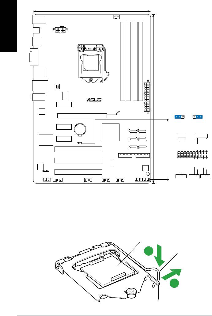
1.2 Motherboard overview 1.2.1 Motherboard layout Ensure that you install the motherboard into the chassis in the correct orientation. The edge with external ports goes to the rear part of the chassis. Place this side towards the rear of the chassis. Place six screws into the holes indicated by circles to secure the motherboard to the chassis. DO NOT overtighten the screws! Doing so can damage the motherboard. 1.2.2 Layout contents Connectors/Jumpers/Slots/LED Page Connectors/Jumpers/Slots/LE
Краткое содержание страницы № 15
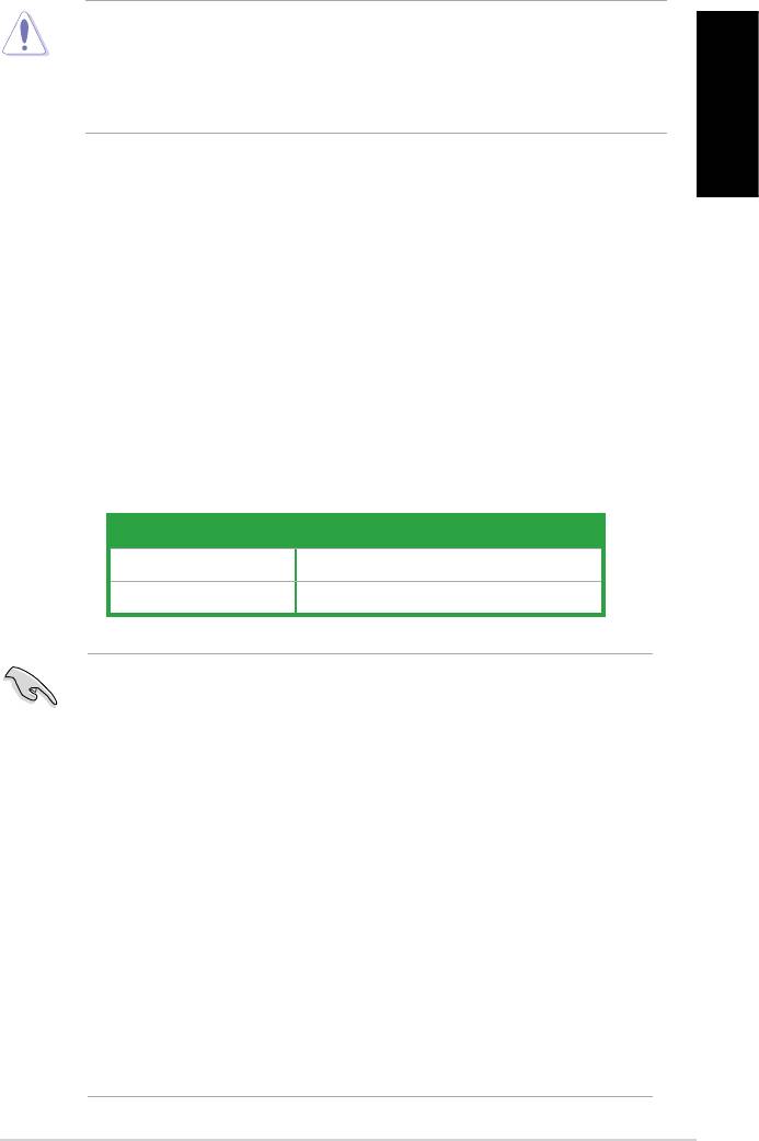
1.3 Central Processing Unit (CPU) ® The motherboard comes with a surface mount LGA1156 socket designed for the Intel Ensure that all power cables are unplugged before installing the CPU. • Upon purchase of the motherboard, ensure that the PnP cap is on the socket and the socket contacts are not bent. Contact your retailer immediately if the PnP cap is missing, or if you see any damage to the PnP cap/socket contacts/motherboard components. ASUS will shoulder the cost of repair only if the da
Краткое содержание страницы № 16
3. Lift the load lever in the direction of the arrow until the load plate is completely lifted. Load plate 4. Remove the PnP cap from the CPU socket by lifting the tab only. PnP cap Cap tab 5. Position the CPU over the socket, ensuring that the gold triangle is on the bottom-left corner of the socket, and then CPU notches fit the socket alignment keys into the CPU notches. The CPU fits in only one correct orientation. DO NOT force the CPU into the socket to prevent bending Gold the c
Краткое содержание страницы № 17
6. Apply some Thermal Interface Material to the exposed area of the CPU that the heatsink will be in contact with, ensuring that it is spread in an even thin layer. Some heatsinks come with pre- applied thermal paste. If so, skip this step. The Thermal Interface Material is toxic and inedible. DO NOT eat it. If it gets into your eyes or touches your skin, wash it off immediately, and seek professional medical help. 7. Close the load plate (A), and then push B down the load lever (B), en
Краткое содержание страницы № 18
1.3.2 Installing the CPU heatsink and fan ® The Intel LGA1156 processor requires a specially designed heatsink and fan assembly to ensure optimum thermal condition and performance. ® • When you buy a boxed Intel processor, the package includes the CPU fan and heatsink assembly. If you buy a CPU separately, ensure that you use only ® Intel -certified multi-directional heatsink and fan. ® • Your Intel LGA1156 heatsink and fan assembly comes in a push-pin design and requires no tool to install
Краткое содержание страницы № 19
3. Connect the CPU fan cable to the connector on the motherboard labeled CPU_FAN. DO NOT forget to connect the CPU fan connector! Hardware monitoring errors can occur if you fail to plug this connector. 1.3.3 Uninstalling the CPU heatsink and fan To uninstall the CPU heatsink and fan: 1. Disconnect the CPU fan cable from the A connector on the motherboard. B 2. Rotate each fastener counterclockwise. B 3. Pull up two fasteners at a time in a diagonal sequence to disengage the heatsink and fa
Краткое содержание страницы № 20
1.4 System memory 1.4.1 Overview The motherboard comes with four Double Data Rate 3 (DDR3) Dual Inline Memory Modules (DIMM) sockets. A DDR3 module has the same physical dimensions as a DDR2 DIMM but is notched differently to prevent installation on a DDR2 DIMM socket. DDR3 modules are developed for better performance with less power consumption. The figure illustrates the location of the DDR3 DIMM sockets: Recommended memory configurations One DIMM: Install one memory module in slot A1 or B1
P7H55

Регистрация устройства поможет вам управлять его гарантией, получать техническую поддержку и отслеживать статус ремонта.
Регистрация продукта
Руководства пользователя
Версия D073
403.03 KB
Turbo Unlocker (TurboV) Instruction
Версия IE5413
175.64 KB
P55/H55/H57/Q57 FAQ Insert page
Версия G5291
2.73 MB
P7H55 user’s manual (German)
Версия E5291
3.67 MB
P7H55 user’s manual (English)
Версия F5291
2.51 MB
P7H55 user’s manual (French)
-
Драйверы
21
-
Инструкции по эксплуатации
3
Языки:

ASUS P7H55 инструкция по эксплуатации
(66 страниц)
- Языки:Английский
-
Тип:
PDF -
Размер:
3.88 MB -
Описание:
P7H55 user’s manual (English)
Просмотр

ASUS P7H55 инструкция по эксплуатации
(1 страница)
- Языки:Английский
-
Тип:
PDF -
Размер:
407.58 KB
Просмотр

ASUS P7H55 инструкция по эксплуатации
(71 страница)
- Языки:Французский
-
Тип:
PDF -
Размер:
4.04 MB -
Описание:
P7H55 user’s manual (French)
Просмотр
На NoDevice можно скачать инструкцию по эксплуатации для ASUS P7H55. Руководство пользователя необходимо для ознакомления с правилами установки и эксплуатации ASUS P7H55. Инструкции по использованию помогут правильно настроить ASUS P7H55, исправить ошибки и выявить неполадки.

U5337
P7H55-V
Motherboard
Quick Start Guide
Français
Deutsh
Italiano
Español
Русский
Português
Polski
Česky
Magyar
Български
Română
Srpski
Türkçe
First Edition
January 2010
Copyright © 2010 ASUSTeK COMPUTER INC.
All Rights Reserved
1. Layout de la carte mère
Français
2. Installer le CPU
Pour installer le CPU :
1. Pressez le levier avec votre pouce (A) et déplacez-le vers la gauche (B)
jusqu’à ce qu’il soit libéré de son onglet de rétention.
Capuchon PnP
Levier
Languette de
retenue
2
ASUS P7H55-V
21.1cm(8.3in)
KB_USB56
CPU_FAN
SPDIF_O2
EATX12V
HDMI
VGA
LGA1156
F_USB34
DDR3 DIMM_A2 (64bit, 240-pin module)
DDR3 DIMM_A1 (64bit, 240-pin module)
DDR3 DIMM_B2 (64bit, 240-pin module)
DDR3 DIMM_B1 (64bit, 240-pin module)
LAN1_USB12
CHA_FAN1
AUDIO
ICS
954 A4
PCIEX1_1
P7H55-V
30.5cm(12.0in)
RTL
EATXPWR
CLRTC
8111E
1 2 2 3
PCIEX16
Normal
Clear RTC
PCIEX1_2
Lithium Cell
SATA2 SATA1
(Default)
CMOS Power
Intel
®
H55
SATA4 SATA3
PLED SPEAKER
Super
PCIEX1_3
I/O
CLRTC
SATA6 SATA5
PCI1
PLED+
PLED-
+5V
Ground
Ground
Speaker
PRI_IDE
PANEL
PIN 1
PCI2
VIA
VT6415
ALC
PWR
887
64Mb
Reset
BIOS
Ground
Ground
PCI3
IDE_LED+
IDE_LED-
SPDIF_OUT
SB_PWR
AAFP
COM1
USB1112 USB910 USB78
PANEL
IDE_LED PWRSW RESET
* Requires an ATX power supply
• Pour éviter d’endommager les broches du socket, ne retirez le couvercle
PnP que lors de l’installation d’un CPU.
• Veuillez garder le couvercle en cas de retour du produit.
• La garantie de ce produit ne couvre pas les dommages causés aux broches
du socket.
Français
2. Soulevez le levier jusqu’à ce que la plaque de chargement soit complètement
ouverte..
3. Retirez le cache PnP du socket du CPU.
4. Placez le CPU sur le socket, en vous assurant que la marque en forme de
triangle doré est placée en bas à gauche du socket. Les ergots d’alignement
du socket doivent correspondre aux encoches du CPU.
5. Refermez la plaque, puis pressez le levier jusqu’à ce qu’il se loge dans le
loquet de rétention.
3. Mémoire Système
Vous pouvez installer des DIMM DDR3 unbuffered non-ECC de 512 MO, 1 Go, 2 Go
et 4 Go dans les sockets.
Canal Emplacements
Canal A DIMM_A1 et DIMM_A2
Canal B DIMM_B1 et DIMM_B2
• Vous pouvez installer des modules mémoire de tailles variables dans le Canal A et B.
Le système mappe la taille totale du canal de plus petite taille pour les congurations
dual-channel. Tout excédant de mémoire du canal le plus grand est alors mappé pour
fonctionner en single-channel.
• En raison de certaines limitations des plate-formes Intel, les modules mémoire X.M.P
ne sont pris en charge qu’à raison d’un module mémoire par canal.
• Installez toujours des
modules mémoire avec une latence CAS identique. Pour obtenir
une compatibilité optimale, il vous est recommandé de vous équiper des modules de
mémoire auprès du même vendeur.
• En raison des limitations d’adressage mémoire sur les systèmes d’exploitation
Windows 32-bits, lorsque vous installez 4Go ou plus de mémoire sur cette carte mère,
le montant de mémoire utilisable par le système d’exploitation sera de 3 Go ou moins.
Pour une utilisation effective de la mémoire, vous pouvez :
— Utiliser un maximum de 3 Go lors de l’utilisation d’un système
d’exploitation 32-bits.
— Installer un système d’exploitation Windows 64-bits si vous souhaitez installer 4
Go ou plus de mémoire sur cette carte mère.
• Cette carte mère ne prend pas en charge les modules mémoire composés de puces
de 512Mb (64Mo) ou moins.
ASUS P7H55-V
3

1
Ру
сс
ки
й
ASUS P7H55-M
1.
Формат материнской платы
2.
Установка процессора
Для установки процессора выполните следующее:
1.
Нажмите на удерживающий рычаг большим пальцем (А), затем перемещайте его влево
(В) до тех пор, пока он не высвободится из-под фиксирующего язычка.
Удерживающий
рычаг
Фиксирующий
язычок
Отметка PnP
A
B
P7H55-M
PCIEX16
PCI1
PCIEX1_1
PCIEX1_2
LPT
USB1112 USB910
USB78
AAFP
ATX12V
EATXPW
R
CPU_FAN
CHA_FAN1
Lithium Cell
CMOS Power
Super
I/O
AUDIO
IC
S
9LRS954A
4
ALC
887
RTL
8111E
KB_USB56
64Mb
BIOS
SB_PWR
CLRTC
SPDIF_OUT
24.4cm(9.6in)
LGA1156
Intel
®
H55
DDR3 DIMM_A2 (64bit, 240-pin module)
DDR3 DIMM_A1 (64bit, 240-pin module)
DDR3 DIMM_B2 (64bit, 240-pin module)
DDR3 DIMM_B1 (64bit, 240-pin module)
LAN1_USB12
F_USB34
SATA1
SATA3
SATA5
SATA2
SATA4
SATA6
VG
A
PRI_EIDE
PANEL
SPDIF_O2
HDMI
COM1
22.4cm(8.8in)
1 2
2 3
Normal
(Default)
Clear RTC
CLRTC
PIN 1
* Requires an ATX power supply
PLED
SPEAKER
PLED
+
PLED
—
+5V
Groun
d
Groun
d
Speake
r
IDE_LED
+
IDE_LED
—
PWR
Groun
d
Rese
t
Groun
d
PANEL
IDE_LED
PWRSW
RESET