На этой странице размещены каталоги и инструкции на кондиционеры McQuay.
Каталог McQuay системы кондиционирования 2015.pdf
Каталог McQuay кассетные кондиционеры.pdf
Каталог McQuay настенные кондиционеры A5WM серии L,J,G 2011.pdf
Каталог McQuay оборудование 2009.pdf
Каталог MCQUAY бытовые кодиционеры 2012.pdf
Каталог McQuay мультисплит-системы.pdf
Каталог McQuay напольно-подпотолочные кондиционеры.pdf
Каталог McQuay настенные серии G.pdf
Каталог McQuay оборудование 2006.pdf
Каталог McQuay оборудование 2007.pdf
Каталог McQuay сплит-система M5LCY-10DR, M5LCY-15DR.pdf
Каталог McQuay Ceiling Concealed Split Systems MCC-2009.pdf
Каталог McQuay DC Inverter Multi Split M5MSX-2008.pdf
Каталог McQuay Multi-Split Systems MMS 2008.pdf
Каталог McQuay бытовое оборудование 2011.pdf
Каталог McQuay системы промышленного кондиционирования 2012.pdf
Каталог McQuay чиллеры AWS Inverter 2013.pdf
Каталог McQuay чиллеры AWS 2013.pdf
Каталог McQuay чиллеры ATS 2013.pdf
Каталог McQuay чиллеры ACZ 2013.pdf
Каталог McQuay оборудование 2013.pdf
Каталог McQuay бытовые и полупромышленные 2014.pdf
Каталог McQuay Infinity 2013.pdf
Каталог McQuay Essential 2013.pdf
Каталог McQuay Energy 2013.pdf
Руководство по обслуживанию McQuay канальные кондиционеры TMMDB-B-2140В.pdf
Руководство по эксплуатации McQuay ПДУ G4.pdf
Руководство по эксплуатации McQuay ПДУ G6.pdf
Руководство по эксплуатации McQuay ПДУ G7.pdf
Руководство по эксплуатации McQuay проводной пульт управления MC-CCS02B(MC303).pdf
Руководство по эксплуатации McQuay M5WMY10KR2010.pdf
Руководство по эксплуатации McQuay HAC 400 2001г.pdf
Руководство по эксплуатации McQuay MWME, MWMER, MLCB, MLCBR.pdf
Руководство по эксплуатации McQuay MCM(020-050) MLC(020-050).pdf
Руководство по эксплуатации McQuay MWM(015-025) MLC(015-020).pdf
Инструкция по монтажу McQuay IM-CECBW-0706.pdf
Инструкция по монтажу McQuay IM-SBBW-1102.pdf
Инструкция по монтажу McQuay IM-WMFW-0501.pdf
Инструкция по монтажу McQuay IM-WMGW-1205.pdf
Инструкция по монтажу McQuay фанк-ойлы серии MFU.pdf
Инструкция по монтажу McQuay чиллер IM-CCCW-1100.pdf
Инструкция по эксплуатации McQuay 401 B–04-11E.pdf
Инструкция по эксплуатации McQuay 401 C-98-10A.pdf
Инструкция по эксплуатации McQuay 402 B–04-11E.pdf
Инструкция по эксплуатации McQuay 403 B–04-11E.pdf
Инструкция по эксплуатации McQuay 403 C–02-06C.pdf
Инструкция по эксплуатации McQuay MWMS 010E,MWMS 010-020F,MMSD 1010-2020A.pdf
Инструкция по эксплуатации McQuay фанк-ойлы серии MCW.pdf
Инструкция пользователя McQuay Fan Coil MMCW200CD-MCW1200CD.pdf
Инструкция пользователя McQuay MCW-CFH (50 Гц) 2008.pdf
Инструкция пользователя McQuay MFU-C MFU-H,MFC-C MFC-H.pdf
Инструкция пользователя McQuay MWM 007-010E,MWM 007-010ER,MLC 007-010B.pdf
Инструкция пользователя McQuay MWM 007-025G GR,M5WM 007-025G GR.pdf
Инструкция пользователя McQuay канальные фанкойлы серии МСC 2009.pdf
Инструкция сервисная McQuay AC040-058A,AC040-058AR,AC075-125B,AC075-125BR.pdf
Инструкция сервисная McQuay M5MSX 2006.pdf
Инструкция сервисная McQuay M5MSX 2008.pdf
Инструкция сервисная McQuay MCC M5CC 010-050C CR.pdf
Инструкция сервисная McQuay MCW-C F H 2006.pdf
Инструкция сервисная McQuay чиллеры 4AC,MAC,YA,AC 80C-100C-120C-150C.pdf
Инструкция сервисная McQuay M5MSYBR.pdf
Инструкция сервисная McQuay MWM-G2.pdf
Инструкция сервисная McQuay M5LCY10-25CR.pdf
Инструкция сервисная McQuay MCM020-030D-DR MCM-M5CM040-062D-DR.pdf
Инструкция сервисная McQuay MWM-GW MCM-DW-EW MCK-AW-BW-CW MCC-CW MDB-BW.pdf
Техническое руководство McQuay Ducted Blower Split Systems MDB – 2005.pdf
Техническое руководство McQuay Ducted Blower Split Systems MDB – E – 2005.pdf
Техническое руководство McQuay канальные сплит-системы MDB 2004.pdf
Техническое руководство McQuay сплит-системы настенного типа MWM – J – 2009.pdf
Руководство по техническому обслуживанию оборудования McQuay.pdf
Таблица теплопроизводительности чиллеров McSmart McQuay.pdf
На этой странице размещены каталоги McQuay.
Вы можете бесплатно скачать каталог, инструкцию, руководство McQuay с нашего сайта.
-
Contents
-
Table of Contents
-
Troubleshooting
-
Bookmarks
Quick Links
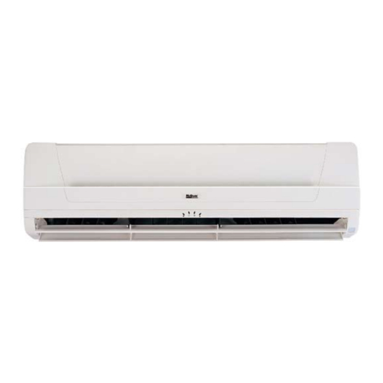
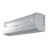
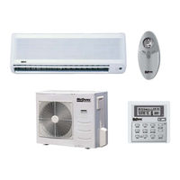
Wall Mounted Split Systems
Models: MWM 007G/GR
MWM 009G/GR
MWM 010G/GR
MWM 015G/GR
MWM 020G/GR
MWM 025G/GR
M5WM 007G/GR
M5WM 009G/GR
M5WM 010G/GR
M5WM 015G/GR
M5WM 020G/GR
M5WM 025G/GR
MWM — G — 2005
Related Manuals for McQuay MWM 007G
Summary of Contents for McQuay MWM 007G
-
Page 1
MWM — G — 2005 Wall Mounted Split Systems Models: MWM 007G/GR M5WM 007G/GR MWM 009G/GR M5WM 009G/GR MWM 010G/GR M5WM 010G/GR MWM 015G/GR M5WM 015G/GR MWM 020G/GR M5WM 020G/GR MWM 025G/GR M5WM 025G/GR… -
Page 2: Table Of Contents
«McQuay» is a registered trademark of McQuay International. All rights reserved throughout the world. c 2005 McQuay International «Bulletin illustrations cover the general appearance of McQuay International products at the time of publication and we reserve the right to make changes in design and construction at any time without notice.»…
-
Page 3: Features
F F F F F ea ea tur tur es • Easy Installation The wall mounted fan coil unit is easily installed because of its compact size, slimness and light weight. Slim and short outdoor unit can be easily installed even in a narrow balcony and passageway and yet have a stable profile.
-
Page 4
• High Efficiency Heat Exchanger — The compact design of the 3-fold structure heat exchanger provides a large surface are for better and efficient heat exchange. The unique Hydrophilic slit fin has greatly improved the air flow and the contact surfaces with the air thus to boost the cooling capacity. -
Page 5: Specifications
Specif Specif ica Specif ica tions tions tions tions Specif Specif tions R22 Models (Cooling only) INDOOR UNIT MWM 009G MWM 010G MWM 015G MODEL OUTDOOR UNIT MLC 009C MLC 010C MLC 015C 2640 2780 3520 NOMINAL COOLING CAPACITY Btu/h 9000 9500 12000…
-
Page 6
R22 Models (Cooling only) INDOOR UNIT MWM 020G MWM 025G MODEL OUTDOOR UNIT MLC 020C MLC 025C 5569 7034 NOMINAL COOLING CAPACITY Btu/h 19000 24000 INPUT POWER W (50 Hz) 1745 2448 RUNNING CURRENT A (50Hz) 12.3 POWER SOURCE V/Ph/Hz 220-240/1/50 REFRIGERANT / CONTROL R22 / OUTDOOR CAP. -
Page 7
R22 Models (Heatpump) INDOOR UNIT MWM 009GR MWM 010GR MWM 015GR MODEL OUTDOOR UNIT MLC 009CR MLC 010CR MLC 015CR 2640 2780 3520 NOMINAL COOLING CAPACITY 9000 Btu/h 9500 12000 2640 2780 3520 NOMINAL HEATING CAPACITY Btu/h 9000 9500 12000 INPUT POWER (COOLING) W (50 Hz) 1100… -
Page 8
R22 Models (Heatpump) INDOOR UNIT MWM 020GR MWM 025GR MODEL OUTDOOR UNIT MLC 020CR MLC 025CR 5569 7034 NOMINAL COOLING CAPACITY Btu/h 19000 24000 5569 7327 NOMINAL HEATING CAPACITY Btu/h 19000 25000 INPUT POWER (COOLING) W (50 Hz) 1715 2412 INPUT POWER (HEATING) W (50 Hz) 1802… -
Page 9
R407C Models (Cooling only) INDOOR UNIT MWM 007G MWM 010G MWM 015G MODEL OUTDOOR UNIT M4LC 007B M4LC 010B M4LC 015B 2169 2638 3224 NOMINAL COOLING CAPACITY Btu/h 7400 9000 11000 INPUT POWER W (50 Hz) 1438 RUNNING CURRENT A (50Hz) 3.64… -
Page 10
R407C Models (Cooling only) INDOOR UNIT MWM 020G MWM 025G MODEL OUTDOOR UNIT M4LC 020B M4LC 025B 5363 6155 NOMINAL COOLING CAPACITY Btu/h 18300 21000 INPUT POWER 2295 2862 RUNNING CURRENT 13.35 10.69 POWER SOURCE V/Ph/Hz 220-240/1/50 REFRIGERANT / CONTROL R22 / OUTDOOR CAP. -
Page 11
R407C Models (Heatpump) INDOOR UNIT MWM 007GR MWM 010GR MWM 015GR MODEL OUTDOOR UNIT M4LC 007BR M4LC 010BR M4LC 015BR 2227 2638 3224 NOMINAL COOLING CAPACITY Btu/h 7600 9000 11000 2169 2784 3663 NOMINAL HEATING CAPACITY Btu/h 7400 9500 12500 INPUT POWER (COOLING) W (50 Hz) 1441… -
Page 12
R407C Models (Heatpump) INDOOR UNIT MWM 020GR MWM 025GR MODEL OUTDOOR UNIT M4LC 020BR M4LC 025BR 5129 6008 NOMINAL COOLING CAPACITY Btu/h 17500 20500 5569 7034 NOMINAL HEATING CAPACITY Btu/h 19000 24000 2185 2773 INPUT POWER (COOLING) W (50 Hz) INPUT POWER (HEATING) W (50 Hz) 2279… -
Page 13
R410A Models (Cooling only) INDOOR UNIT M5WM 007G M5WM 009G M5WM 010G M5WM 015G MODEL OUTDOOR UNIT M5LC 007C M5LC 010C M5LC 010C M5LC 015C 2200 2640 2780 3520 NOMINAL COOLING CAPACITY Btu/h 7500 9000 9500 12000 INPUT POWER W (50 Hz) 1230 RUNNING CURRENT A (50Hz) -
Page 14
R410A Models (Cooling only) INDOOR UNIT M5WM 020G M5WM 025G MODEL OUTDOOR UNIT M5LC 020C M5LC 025C 5569 7034 NOMINAL COOLING CAPACITY Btu/h 19000 24000 INPUT POWER W (50 Hz) 1865 2602 RUNNING CURRENT A (50Hz) 12.4 POWER SOURCE V/Ph/Hz 220-240/1/50 REFRIGERANT / CONTROL R410A / OUTDOOR CAP.TUBE… -
Page 15
R410A Models (Heatpump) INDOOR UNIT M5WM 007GR M5WM 009GR M5WM 010GR M5WM 015GR MODEL OUTDOOR UNIT M5LC 007CR M5LC 010CR M5LC 010CR M5LC 015CR 2200 2640 2780 3520 NOMINAL COOLING CAPACITY Btu/h 7500 9000 9500 12000 2200 2640 2780 3520 NOMINAL HEATING CAPACITY Btu/h 7500… -
Page 16
R410A Models (Heatpump) INDOOR UNIT M5WM 020GR M5WM 025GR MODEL OUTDOOR UNIT M5LC 020CR M5LC 025CR 5569 6741 NOMINAL COOLING CAPACITY Btu/h 19000 23000 5569 6741 NOMINAL HEATING CAPACITY Btu/h 19000 23000 1921 2615 INPUT POWER (COOLING) W (50 Hz) INPUT POWER (HEATING) W (50 Hz) 1882… -
Page 17: Performance Table
Performance Table Interpolation and Extrapolation method can be used to get the total capacity, TC and sensible capacity, SC at those temperatures which are not stated out in the table. Example: Model: MWM 010G / MLC 010C Indoor Condition: 23°C DB, 15°C WB Outdoor Condition: 37°C DB Solution: Overall…
-
Page 18
Details: Step: To obtain the Total capacity and Sensible capacity for (a) Indoor Condition: 24°C DB, 15°C WB Outdoor Condition: 35°C DB Outdoor DB ° C Indoor DB Indoor WB ° C ° C TC (kW) SC (kW) 2.624 1.888 2.688 1.790 Total capacity, TC… -
Page 19
Step: To obtain the Total capacity and Sensible capacity for (a) Indoor Condition: 23°C DB, 15°C WB Outdoor Condition: 35°C DB Outdoor DB ° C Indoor DB Indoor WB ° C ° C TC (kW) SC (kW) 2.560 1.398 2.560 1.985 Total capacity, TC ⇒… -
Page 20
Step: To obtain the Total capacity and Sensible capacity for (a) Indoor Condition: 23°C DB, 15°C WB Outdoor Condition: 37°C DB Outdoor DB ° C Indoor DB Indoor WB ° C ° C TC (kW) SC (kW) TC (kW) SC (kW) TC (kW) SC (kW) 2.560… -
Page 21
R22 Models (Cooling Only) Model : MWM 009G / MLC 009C Outdoor DB°C ID DB°C ID WB°C TC(kW) SC(kW) TC(kW) SC(kW) TC(kW) SC(kW) TC(kW) SC(kW) TC(kW) SC(kW) TC(kW) SC(kW) 3.164 2.057 2.935 1.847 2.706 1.636 2.477 1.426 2.248 1.215 1.973 0.963 3.206 1.890… -
Page 22
R22 Models (Cooling Only) Model : MWM 015G / MLC 015C Outdoor DB°C ID DB°C ID WB°C TC(kW) SC(kW) TC(kW) SC(kW) TC(kW) SC(kW) TC(kW) SC(kW) TC(kW) SC(kW) TC(kW) SC(kW) 3.852 2.383 3.608 2.178 3.365 1.973 3.121 1.769 2.877 1.564 2.584 1.318 4.062 2.259… -
Page 23
R22 Models (Heatpump) Model : MWM 009GR / MLC 009CR COOLING MODE Outdoor DB°C ID DB°C ID WB°C TC(kW) SC(kW) TC(kW) SC(kW) TC(kW) SC(kW) TC(kW) SC(kW) TC(kW) SC(kW) TC(kW) SC(kW) 3.164 2.057 2.935 1.847 2.706 1.636 2.477 1.426 2.248 1.215 1.973 0.963 3.206… -
Page 24
R22 Models (Heatpump) Model : MWM 010GR / MLC 010CR COOLING MODE Outdoor DB°C ID DB°C ID WB°C TC(kW) SC(kW) TC(kW) SC(kW) TC(kW) SC(kW) TC(kW) SC(kW) TC(kW) SC(kW) TC(kW) SC(kW) 3.170 1.962 2.967 1.774 2.763 1.586 2.560 1.398 2.356 1.211 2.112 0.985 3.207… -
Page 25
R22 Models (Heatpump) Model : MWM 015GR / MLC 015CR COOLING MODE Outdoor DB°C ID DB°C ID WB°C TC(kW) SC(kW) TC(kW) SC(kW) TC(kW) SC(kW) TC(kW) SC(kW) TC(kW) SC(kW) TC(kW) SC(kW) 3.852 2.383 3.608 2.178 3.365 1.973 3.121 1.769 2.877 1.564 2.584 1.318 4.062… -
Page 26
R407C Models (Cooling Only) Model : MWM 007G / M4LC 007B Outdoor DB°C ID DB°C ID WB°C TC(kW) SC(kW) TC(kW) SC(kW) TC(kW) SC(kW) TC(kW) SC(kW) TC(kW) SC(kW) TC(kW) SC(kW) 2.629 1.618 2.438 1.439 2.247 1.261 2.056 1.083 1.865 0.904 1.636 0.690… -
Page 27
R407C Models (Cooling Only) Model : MWM 015G / M4LC 015B Outdoor DB°C ID DB°C ID WB°C TC(kW) SC(kW) TC(kW) SC(kW) TC(kW) SC(kW) TC(kW) SC(kW) TC(kW) SC(kW) TC(kW) SC(kW) 3.531 2.093 3.308 1.905 3.084 1.717 2.861 1.529 2.637 1.342 2.369 1.116 3.723 1.979… -
Page 28
R407C Models (Heatpump) Model : MWM 007GR / M4LC 007BR COOLING MODE Outdoor DB°C ID DB°C ID WB°C TC(kW) SC(kW) TC(kW) SC(kW) TC(kW) SC(kW) TC(kW) SC(kW) TC(kW) SC(kW) TC(kW) SC(kW) 2.701 1.684 2.504 1.501 2.308 1.318 2.112 1.134 1.915 0.951 1.680 0.732 2.707… -
Page 29
R407C Models (Heatpump) Model : MWM 010GR / M4LC 010BR COOLING MODE Outdoor DB°C ID DB°C ID WB°C TC(kW) SC(kW) TC(kW) SC(kW) TC(kW) SC(kW) TC(kW) SC(kW) TC(kW) SC(kW) TC(kW) SC(kW) 3.004 1.807 2.811 1.629 2.618 1.451 2.425 1.273 2.232 1.095 2.000 0.882 3.038… -
Page 30
R407C Models (Heatpump) Model : MWM 015GR / M4LC 015BR COOLING MODE Outdoor DB°C ID DB°C ID WB°C TC(kW) SC(kW) TC(kW) SC(kW) TC(kW) SC(kW) TC(kW) SC(kW) TC(kW) SC(kW) TC(kW) SC(kW) 3.531 2.093 3.308 1.905 3.084 1.717 2.861 1.529 2.637 1.342 2.369 1.116 3.723… -
Page 31
R410A Models (Cooling Only) Model : M5WM 007G / M5LC 007C Outdoor DB°C ID DB°C ID WB°C TC(kW) SC(kW) TC(kW) SC(kW) TC(kW) SC(kW) TC(kW) SC(kW) TC(kW) SC(kW) TC(kW) SC(kW) 2.542 1.626 2.345 1.429 2.152 1.237 1.960 1.044 1.767 0.851 1.535 0.620 2.589 1.510… -
Page 32
R410A Models (Cooling Only) Model : M5WM 010G / M5LC 010C Outdoor DB°C ID DB°C ID WB°C TC(kW) SC(kW) TC(kW) SC(kW) TC(kW) SC(kW) TC(kW) SC(kW) TC(kW) SC(kW) TC(kW) SC(kW) 3.029 1.991 2.825 1.787 2.633 1.595 2.440 1.402 2.248 1.210 2.017 0.979 3.111 1.851… -
Page 33
R410A Models (Heatpump) Model : M5WM 007GR / M5LC 007CR COOLING MODE Outdoor DB°C ID DB°C ID WB°C TC(kW) SC(kW) TC(kW) SC(kW) TC(kW) SC(kW) TC(kW) SC(kW) TC(kW) SC(kW) TC(kW) SC(kW) 2.248 1.516 2.115 1.383 1.997 1.265 1.879 1.147 1.761 1.028 1.619 0.887 2.329… -
Page 34
R410A Models (Heatpump) Model : M5WM 009GR / M5LC 010CR COOLING MODE Outdoor DB°C ID DB°C ID WB°C TC(kW) SC(kW) TC(kW) SC(kW) TC(kW) SC(kW) TC(kW) SC(kW) TC(kW) SC(kW) TC(kW) SC(kW) 2.721 1.766 2.556 1.601 2.407 1.452 2.258 1.303 2.109 1.153 1.929 0.974 2.817… -
Page 35
R410A Models (Heatpump) Model : M5WM 010GR / M5LC 010CR COOLING MODE Outdoor DB°C ID DB°C ID WB°C TC(kW) SC(kW) TC(kW) SC(kW) TC(kW) SC(kW) TC(kW) SC(kW) TC(kW) SC(kW) TC(kW) SC(kW) 2.910 1.878 2.702 1.670 2.503 1.470 2.303 1.271 2.104 1.072 1.864 0.832 3.003… -
Page 36
R410A Models (Heatpump) Model : M5WM 015GR / M5LC 015CR COOLING MODE Outdoor DB°C ID DB°C ID WB°C TC(kW) SC(kW) TC(kW) SC(kW) TC(kW) SC(kW) TC(kW) SC(kW) TC(kW) SC(kW) TC(kW) SC(kW) 3.618 2.382 3.427 2.167 3.205 1.971 2.983 1.776 2.761 1.580 2.495 1.345 3.728… -
Page 37: Noise Level
Model (RPM) 125 Hz 250 Hz 500 Hz 1 kHz 2 kHz 4 kHz 8 kHz A (dBA) Criteria HIGH MWM 007G/GR MWM 009G/GR MEDIUM M5WM 007G/GR M5WM 009G/GR HIGH MWM 010G/GR MEDIUM M5WM 010G/GR HIGH MWM 015G/GR MEDIUM M5WM 015G/GR Microphone position: 1m in front and 0.8m below the vertical centre line of the unit.
-
Page 38
MWM 007 / 009 G/GR , M5WM 007 / 009 G/GR NC CURVES NC-45 NC-40 High Fan NC-35 Medium Fan NC-30 Low Fan NC-25 NC-20 1000 2000 4000 8000 Octave-band frequency (Hz) Measured in anechoic room at 1m in front and 0.8m below the vertical centre line of the unit MWM 010 G/GR , M5WM 010 G/GR NC CURVES NC-45… -
Page 39
MWM 015 G/GR , M5WM 015 G/GR NC CURVES NC-45 NC-40 High Fan NC-35 Medium Fan NC-30 NC-25 NC-20 Low Fan 1000 2000 4000 8000 Octave-band frequency (Hz) Measured in anechoic room at 1m in front and 0.8m below the vertical centre line of the unit… -
Page 40: Operating Range
Operating Range Ensure the operating temperature is in allowable range. Cooling only Cooling HIGH AMBIENT UNIT Caution : The use of your air conditioner outside the range of working temperature and humidity can result in serious failure. LOW AMBIENT Indoor temp. (°CWB) Heatpump Heating Cooling…
-
Page 41: Refrigeration Cycle Diagram
Refrigeration Cycle Diagram Cooling Only Models Model : MLC 009C / 010C / 015C M4LC 007B / 010B / 015B M5LC 007C / 010C / 015C…
-
Page 42
Cooling Only Models Model : MLC / M5LC 020C M4LC 020B Model : MLC / M5LC 025C M4LC 025B… -
Page 43
Heatpump Models Model : MLC / M5LC 007CR Model : M4LC 007BR / 010BR MLC / M5LC 010CR… -
Page 44
Model : M4LC 015BR Model : MLC / M5LC 015CR… -
Page 45
Heatpump Models Model : MLC / M5LC 020CR M4LC 020BR Model : MLC / M5LC 025CR M4LC 025BR… -
Page 46: Outlines And Dimension
Outlines And Dimension Indoor Unit Model : MWM 007G / 007GR / 009G / 009GR M5WM 007G / 007GR / 009G / 009GR Note : Dimension in mm Outdoor Unit Model : MLC 009C / 009CR M5LC 007C / 007CR…
-
Page 47
Indoor Unit Model : MWM 010G / 010GR / 015G / 015GR M5WM 010G / 010GR / 015G / 015GR Note : Dimension in mm Outdoor Unit Model : MLC 010C / 010CR / 015C / 015CR M5LC 010C / 010CR / 015C / 015CR Note : Dimension in mm… -
Page 48
Indoor Unit Model : MWM 020G / 020GR / 025G / 025GR M5WM 020G / 020GR / 025G / 025GR Note : Dimension in mm Outdoor Unit Model : MLC 020C / 020CR / 025C / 025CR M5LC 020C / 020CR / 025C / 025CR For M5LC / MLC 025 C/CR Only Note : Dimension in mm MODEL… -
Page 49
Indoor Unit Model : MWM 007G / 007GR Note : Dimension in mm Outdoor Unit Model : M4LC 007B / 007BR Note : Dimension in mm… -
Page 50
Indoor Unit Model : MWM 010G / 010GR / 015G / 015GR Note : Dimension in mm Outdoor Unit Model : M4LC 010B / 010BR / 015B / 015BR Note : Dimension in mm… -
Page 51
Indoor Unit Model : MWM 020G / 020GR / 025G / 025GR Note : Dimension in mm Outdoor Unit Model : M4LC 020B / 020BR / 025B / 025BR Note : Dimension in mm… -
Page 52: Wiring Diagrams
Wiring Diagrams Cooling Only Models Outdoor Unit Model : MLC 009C / 010C, M5LC 007C / 010C / 015C Indoor Unit Model : MWM 009G / 010G, M5WM 007G / 009G / 010G / 015G (With Ionizer)
-
Page 53
Cooling Only Models Outdoor Unit Model : MLC 015C Indoor Unit Model : MWM 015G (With Ionizer) -
Page 54
Cooling Only Models Outdoor Unit Model : MLC / M5LC 020C / 025C Indoor Unit Model : MWM / M5WM 020G / 025G (With Ionizer) -
Page 55
Cooling Only Models Outdoor Unit Model : MLC 009C / 010C , M5LC 007C / 010C / 015C Indoor Unit Model : MWM 009G / 010G , M5WM 007G / 009G / 010G / 015G (With NTP) -
Page 56
Cooling Only Models Outdoor Unit Model : MLC 015C Indoor Unit Model : MWM 015G (With NTP) -
Page 57
Cooling Only Models Outdoor Unit Model : MLC / M5LC 020C / 025C Indoor Unit Model : MWM / M5WM 020G / 025G (With NTP) -
Page 58
Cooling Only Models Outdoor Unit Model : M4LC 007B / 010B / 015B Indoor Unit Model : MWM 007G / 010G / 015G (With Ionizer) -
Page 59
Cooling Only Models Outdoor Unit Model : M4LC 020B / 025B Indoor Unit Model : MWM / M5WM 020G / 025G (With Ionizer) -
Page 60
Cooling Only Models Outdoor Unit Model : M4LC 007B / 010B / 015B Indoor Unit Model : MWM 007G / 010G / 015G (With NTP) -
Page 61
Cooling Only Models Outdoor Unit Model : M4LC 020B / 025B Indoor Unit Model : MWM / M5WM 020G / 025G (With NTP) -
Page 62
Cooling Only Models Outdoor Unit Oxygen Unit Model : MLC 010C , M5LC 010C / 015C… -
Page 63
Heatpump Models Outdoor Unit Model : MLC 009CR / 010CR , M5LC 007CR / 010CR / 015CR Indoor Unit Model : MWM 009GR / 010GR , M5WM 007GR / 010GR / 015GR (With Ionizer) -
Page 64
Heatpump Models Outdoor Unit Model : MLC 015CR Indoor Unit Model : MWM 015GR (With Ionizer) -
Page 65
Heatpump Models Outdoor Unit Model : MLC / M5LC 020CR / 025CR Indoor Unit Model : MWM / M5WM 020GR / 025GR (With Ionizer) -
Page 66
Heatpump Models Outdoor Unit Model : MLC 009CR / 010CR , M5LC 007CR / 010CR / 015CR Indoor Unit Model : MWM 009GR / 010GR , M5WM 007GR / 009GR / 010GR / 015GR (With NTP) -
Page 67
Heatpump Models Outdoor Unit Model : MLC 015CR Indoor Unit Model : MWM 015GR (With NTP) -
Page 68
Heatpump Models Outdoor Unit Model : MLC / M5LC 020CR / 025CR Indoor Unit Model : MWM / M5WM 020GR / 025GR (With NTP) -
Page 69
Heatpump Models Outdoor Unit Model : M4LC 007BR / 010BR / 015BR Indoor Unit Model : MWM 007GR / 010GR / 015GR (With Ionizer) -
Page 70
Heatpump Models Outdoor Unit Model : M4LC 020BR / 025BR Indoor Unit Model : MWM / M5WM 020G / 025G (With Ionizer) -
Page 71
Heatpump Models Outdoor Unit Model : M4LC 007BR / 010BR / 015BR Indoor Unit Model : MWM 007GR / 010GR / 015GR (With NTP) -
Page 72
Heatpump Models Outdoor Unit Model : M4LC 020BR / 025BR Indoor Unit Model : MWM / M5WM 020G / 025G (With NTP) -
Page 73: Safety Precautions Before Installation
Safety Precautions Before Installation BEFORE OPERATING, PLEASE READ THE FOLLOWING “SAFETY PRECAUTIONS” CAREFULLY. To prevent injury to the user or other people and properties damage, the following instructions must be followed. Incorrect operation due to ignoring of instruction will cause harm or damage, the seriousness is classified by the following indications.
-
Page 74
Symbol (with white background) denotes item that is PROHIBITED from doing. Symbol (with black background) denotes item that is COMPULSORY to be carried Caution Please confirm the following important points when installation • Grounding is necessary It may cause electrical shock if grounding is not perfect. •… -
Page 75: Special Precautions For R407C
Special Precautions For R407C SPECIAL PRECAUTIONS WHEN DEALING WITH REFRIGERANT R407C UNIT 1) WHAT IS NEW REFRIGERANT R407C? R407C is a zeotropic refrigerant mixture which has Zero Ozone Depletion Potential (ODP = 0) and thus conformed to the Montreal Protocol regulation. It requires Polyol-ester oil (POE) oil for its compressor’s lubricant.
-
Page 76
c) Ensure that the compressor is not expose to open air for more than the recommended time specified by its manufacturer (typically less than 10 minutes). Removed the seal plugs only when the compressor is about to be brazed. d) The system should be thoroughly vacuumed to 1.0 Pa ( 700mmHg) or lower. This vacuuming level is more stringent than R22 system so as to ensure no incompressible gas and moisture in the system. -
Page 77: Special Precautions For R410A
Special Precautions For R410A SPECIAL PRECAUTIONS WHEN DEALING WITH REFRIGERANT R410A UNIT 1) WHAT IS NEW REFRIGERANT R410A? R410A is a new HFC refrigerant which does not damage the ozone layer. The working pressure of this new refrigerant is 1.6 times higher than conventional refrigerant (R22), thus proper installation / servicing is essential. 2) COMPONENTS Mixture weight composition R32(50%) and R125(50%)
-
Page 78
d) When charging R410A, ensure that only liquid is being withdrawn from the cylinder or can. This is to ensure that only the original composition of R410A is being delivered into the system. The liquid composition can be different from the vapor composition. Invert cylinder Dip-pipe without dip-pipe… -
Page 79: Installation
Installation Installation Diagram…
-
Page 80
CAUTION: Before installing the unit, ensure that the power supply matches the power requirement of the air conditioner. 1) Selection Of Location And Space (A) Indoor Unit Install the fan coil (indoor) unit at a location with the following requirements Location is suitable for wiring, piping and drainage. -
Page 81
(B) Outdoor Unit As condensing temperature rises, evaporating temperature rises and cooling capacity drops. In order to achieve maximum cooling capacity, the location selected for outdoor unit should fulfill the following requirements : Install the condensing (outdoor) unit in a way such that hot air distributed by the outdoor condensing unit cannot be drawn in again (as in the case of short circuit of hot discharge air). -
Page 82
Condensed Water Disposal Of Outdoor Unit (Heatpump Unit Only) There are 2 holes on the base of outdoor unit for condensed water to flow out. Insert the drain elbow to one of the holes. To install the drain elbow, first insert one portion of the hook to the base (portion A), then pull the drain elbow in the direction shown by the arrow while inserting the other portion to the base. -
Page 83
2) Drilling Holes And Mounting Installation Plate CAUTION: i) Please check the unit weight for each model. Always ensure that the wall is sufficiently strong to withstand the weight. If not, it is necessary to reinforce the wall with plate, beams or pillars. ii) The unit cannot be directly fixed onto the wall or the likes. -
Page 84
• Fixing method:- WOODEN REINFORCED CONCRETE BUILDING FRAME WALL NUT ANCHOR BOLT ANCHOR 3) Indoor Unit Preparation • • The refrigerant piping can be routed to the unit in 5 Carefully bend the pipes to the required position to direction, by using the cut outs in the unit casing. align with the hole. -
Page 85
6) Wiring Electrical Connection • Wiring regulation on wire diameters differ from country to country. Please refer to your LOCAL ELECTRICAL CODES for field wiring rules. Be sure that installation comply with such rules and regulations. General Precautions • Ensure that the rated voltage of the unit corresponds to the name plate before carrying out proper wiring according to the wiring diagram. -
Page 86
• Remove burr with the burr remover. Hold the flaring end down to prevent burrs from dropping inside pipe. • The exact length of pipe protruding from the face of the flare die is determined by the flaring tool. The table shows the use of an imperial die and riged die. -
Page 87
• When the piping length is more than 7.6m, please use the table below : Additional charge in gram. R22 & R407C MODELS MWM 007G / 009G / 010G / 015G MWM 020G MWM 025G MWM 007GR / 009GR / 010GR / 015GR… -
Page 88
Diagram shows typical charging method. Note : R407C – Fix filter dryer R22 — Nil R410A — Nil CAUTION FOR R407C / R410A Avoid prolong exposure of an opened compressor, or the internal part of refrigerant piping to moist air. The POE oil in the compressor and piping can absorb moisture from air. 9) Final Checking Ensure that steps 1 to 8 are closely followed. -
Page 89: Remote Controller Operation Guide
Remote Controller Operation Guide G11 Remote Controller Temperature Setting On/Off Button Press Once to start the air To set the desired room conditioner temperature, press the button to increase or decrease the set Press again to stop the unit temperature. The temperature setting range is from 16 C to 30 C Personalised Setting…
-
Page 90
Indicator Lights IR signal receiver When there is infrared remote control operating signal, the signal receiver on indoor unit will made a (beep) for signal acceptance confirmation. IR Receiver LED indicator lights The table below shows the LED indicator light for air conditioner unit under normal operation and fault condition. The LED indicator lights are located at the middle of the air conditioner unit. -
Page 91: Special Function
Special Function Special Function Special Function Special Function Special Function (A) 3 Hot System (Heating Cycle) a) Hot start At the beginning of heating operation (cold start, after defrosting or thermostat resumes operation) the indoor fan operation is controlled in accordance with the temperature of the indoor heat exchanger to send warm air from the start.
-
Page 92
c) Hot spurt During cold start, the set temperature of controller is increased by 2 C to stabilize the room temperature quickly. (B) TURBO Mode TURBO function is available in COOL, HEAT and DRY modes only. When TURBO function is set, working temperature for cooling cycle is decreased by 2 C, working temperature for heating cycle is increased by 2 The indoor fan will force to HIGH fan. -
Page 93
(E) Frost Prevention And Filter Check In order to prevent the freezing of indoor coil, the controller will operate as follow. 1°C (F) Auto Random Restart When power resumed, the unit will automatically restart and operate at the previous setting as before power failure occurred. -
Page 94: Servicing And Maintenance
Ser vicing vicing vicing And Maintenance vicing And Maintenance And Maintenance And Maintenance vicing And Maintenance Off the unit Unscrew the air discharge housing Flip open the air discharge housing Clean the blower Close the air discharge housing and tighten it with screw The unit is designed to give a long life operation with minimum maintenance required.
-
Page 95
Pre Start Up Maintenance (After Extended Shutdown) Inspect thoroughly and clean indoor and outdoor units. – Clean or replace air filters. – Clean condensate drain line. – Clean clogged indoor and outdoor coils. – Check fan imbalance before operation. – Tighten all wiring connections and panels. -
Page 96: Troubleshooting
T T T T T r r r r r oub oub leshooting leshooting leshooting leshooting leshooting By means of pressure readings : PRESSURE PROBABLE CAUSE Data Circuit High Side 1. Overcharged with refrigerant. Low Side 2. Non-condensable gases in refrigerant circuit (e.g. oil). 3.
-
Page 97
The most common causes of air conditioner failure to “start” are : a) Voltage not within +/ 10% of rated voltage. b) Power supply interrupted. c) Control settings improper d) Air Conditioner is disconnected from main power source. e) Fuse blown or circuit breaker off. II) Diagnosis Of Refrigerant Circuit /Application There might be some cases where the unit starts running but does not perform satisfactory, i.e. -
Page 98: Parts List
P P P P P ar ar ts List ts List ts List ts List ts List Indoor Unit Model: M5WM / MWM 007G / 007GR / 009G / 009GR / 010G / 010GR / 015G / 015GR…
-
Page 99
M5WM / MWM 007G / 009G / 010G / 015G No Descriptions Part No No Descriptions Part No Assy., Chassis Air Discharge Housing M5WM / MWM 007/009G A50124064147 M5WM / MWM 007/009G A50124062325 M5WM / MWM 010/015G M5WM / MWM 010/015G… -
Page 100
Model: M5WM / MWM 020G / 020GR / 025G / 025GR… -
Page 101
Model : M5WM / MWM 020G / 025G No Descriptions Part No No Descriptions Part No Assy., Chassis A50124068170 Assy., Control Box A50044071955 Fan, Motor Assy., Control Box Cover A50124071418 MWM 020G Assy., Front Cover A50124071424 A03034074205 MWM 025G Air Discharge Housing A50124071426 A03034074204 Cross Flow Fan… -
Page 102
Outdoor Unit Model: MLC 009C No Descriptions Part No No Descriptions Part No Assy., Base Pan A50014057372 11 Right Panel A01014052509 Assy., Condenser Coil A50024059248 12 Assy. Control Panel A50044054806 Valve Bracket A01014051164 13 Assy., Front Panel A01014052512 Compressor A50049016211 14 Assy., Valve Cover A50124055172 Assy., Partition… -
Page 103
Model: MLC 010C / 015C No Descriptions Part No No Descriptions Part No Assy., Base Pan A50014051158 11 Right Panel A01014051167 Assy., Condenser Coil A50024052499 12 Assy., Front Panel A01014051171 Valve Bracket A01014051164 13 Assy. Control Panel Compressor MLC 010C A50044058195 MLC 010C A04019019550… -
Page 104
Model: MLC 009CR No Descriptions Part No No Descriptions Part No Assy., Base Pan A50014057372 10 Fan Blade A03019004131 Assy., Condenser Coil A50024064204 11 Left Panel A01014052510 Valve Bracket A01014051164 12 Right Panel A01014052509 Compressor 13 Assy. Control Panel A50044059032 MLC 009CR A50049016211 14 Assy., Front Panel… -
Page 105
Model: MLC 010CR / 015CR No Descriptions Part No No Descriptions Part No Assy., Base Pan A50014051158 11 Left Panel A01014051166 Assy., Condenser Coil 12 Right Panel A01014051167 MLC 010CR A50024065601 13 Assy., Front Panel A01014051171 MLC 015CR A50024060071 14 Assy. Control Panel Valve Bracket A01014051164 MLC 010CR… -
Page 106
Outdoor Unit Model: M5LC 007C No Descriptions Part No No Descriptions Part No Assy., Base Pan A50014057372 10 Left Panel A01014052510 Assy., Condenser Coil A50024064720 11 Right Panel A01014052509 Valve Bracket A01014051164 12 Assy. Control Panel A50044054806 Compressor A04019019592 13 Assy., Front Panel A01014052512 Assy., Partition A50064065275… -
Page 107
Model: M5LC 010C / 015C No Descriptions Part No No Descriptions Part No Assy., Base Pan A50014051158 11 Right Panel A01014051167 Assy., Condenser Coil A50024064721 12 Assy., Front Panel A01014051171 Valve Bracket A01014051164 13 Assy. Control Panel Compressor M5LC 010C A50044058195 M5LC 010C A04019019590… -
Page 108
Model: M5LC 007CR No. Descriptions Part No No. Descriptions Part No Assy., Base Pan A50014057372 12 Right Panel A01014052509 Assy., Condenser Coil A50024064720 13 Assy. Control Panel A50044059032 Valve Bracket A01014051164 14 Assy., Front Panel A01014052512 Compressor A04019019592 15 Assy., Valve Cover A50124055172 Assy., Partition A50064065275… -
Page 109
Model: M5LC 010CR / 015CR No. Descriptions Part No No. Descriptions Part No Assy., Base Pan A50014051158 11 Left Panel A01014051166 Assy., Condenser Coil 12 Right Panel A01014051167 M5LC 010CR A50024064721 13 Assy., Front Panel A01014051171 M5LC 015CR A50024066517 14 Assy. Control Panel Valve Bracket A01014051164 M5LC 010CR… -
Page 110
Model: M4LC 007B / 010B / 015B No Descriptions Part No No Descriptions Part No Back Grille A50014041357 10 Assy., Base Pan Top Panel A01010011408 M4LC 007B A50014036357 Assy., Condenser Coil M4LC 010 / 015B A50014013142 M4LC 007B A50024022675 11 Assy., Cap. Tube M4LC 010B A50024043386 M4LC 007B… -
Page 111
Model: M4LC 020B / 025B No. Descriptions Part No No. Descriptions Part No Back Grille A50014043394 11 Assy., Cap. Tube Top Panel A01010011397 M4LC 020B A50024043567 Assy., Condenser Coil M4LC 025B A50024043576 M4LC 020B A50024043566 12 Assy., Partition A50014012920 M4LC 025B A50024043575 13 Assy., Terminal Box Panel A01014047406… -
Page 112
Model: M4LC 007BR / 010BR / 015BR No Descriptions Part No No Descriptions Part No Back Grille A50014041357 11 Assy., Base Pan A50014013142 Top Panel A01010011408 12 Assy., Restrictor Valve Assy., Condenser Coil M4LC 010BR A50024043723 M4LC 007 / 010BR A50024032349 Assy., Cap. -
Page 113
Model: M4LC 020BR / 025BR No. Descriptions Part No No. Descriptions Part No Back Grille A50014043394 12 Assy., Restrictor Valve Top Panel A01010011397 M4LC 020BR A50024042691 Assy., Condenser Coil M4LC 025BR A50024034401 M4LC 020BR A50024021529 13 Assy., Partition A50014012920 M4LC 025BR A50024033948 14 Assy., Terminal Box Panel A50044049929… -
Page 114
Model: M5LC / MLC 020C Description Description Assy. Base Pan Compressor Assy. Outdoor Coil Front Panel (Left) Motor Bracket Service Panel Fan Motor Terminal Cover Panel Nut, Fan Motor Hex Lock Assy. Terminal Panel Fan Blade Top Panel Valve Bracket Front Grille Assy., Flare Valve 3 Ways 5/8″… -
Page 115
Model: M5LC / MLC 025C Description Description Assy. Base Pan Front Panel (Left) Assy. Outdoor Coil Service Panel Motor Bracket Terminal Cover Panel Fan Motor Assy. Terminal Panel Nut, Fan Motor Hex Lock Top Panel Fan Blade Front Grille Valve Bracket Handle Assy., Flare Valve 3 Ways 5/8″… -
Page 116
Model: M5LC / MLC 020CR Description Description Assy. Base Pan Front Panel (Left) Assy. Outdoor Coil Service Panel Motor Bracket Terminal Cover Panel Fan Motor Assy. Terminal Panel Nut, Fan Motor Hex Lock Top Panel Fan Blade Front Grille Valve Bracket Handle Assy., Flare Valve 3 Ways 5/8″… -
Page 117
Model: M5LC / MLC 025CR Description Description Assy. Base Pan Front Panel (Left) Assy. Outdoor Coil Service Panel Motor Bracket Terminal Cover Panel Fan Motor Assy. Terminal Panel Nut, Fan Motor Hex Lock Top Panel Fan Blade Front Grille Valve Bracket Handle Assy., Flare Valve 3 Ways 5/8″… -
Page 118
©2005 McQuay International +1 (800) 432-1342 www.mcquay.com…
РУКОВОДСТВО ПО ИСПОЛЬЗОВАНИЮ
1.
Источник сигналов
• Источник, откуда сигнал будет передаваться.
2.
Индикация передачи сигнала
• Мигает для подтверждения того, что последняя установка была передана на
модуль.
3.
Кнопка «ВКЛ/ВЫКЛ» (ON/OFF)
• Нажмите один раз для включения кондиционера.
• Вновь нажмите для остановки модуля.
4.
Выбор скорости вентилятора
• Нажмите кнопку
в следующем порядке:
• Прекратите нажимание, как только на дисплее экрана появится желаемая
скорость вентилятора.
5.
Режим работы
• Нажмите кнопку MODE (РЕЖИМ) для выбора типа режима работы.
• Только для охлаждения, возможные режимы: COOL ( ) (ХОЛОД), DRY ( )
(ОСУШЕНИЕ) и FAN ( ) (BЕНТИЛЯЦИЯ).
• Для обогревательного насоса возможные режимы: AUTO ( ) (АВТО),
COOL ( ) (ХОЛОД), DRY ( ) (ОСУШЕНИЕ), FAN ( ) (ВЕНТИЛЯЦИЯ) и
HEAT ( ) (ОБОГРЕВ).
• Режим AUTO ( ) (ABTO) недоступен для кондиционеров с водяным
охлаждением.
6.
Автоматический поворот направления жалюзи
• Нажмите кнопку ПОВОРОТ
поворота жалюзи.
• Для распространения воздуха в определенном направлении, нажмите кнопку
ПОВОРОТ
желаемом направлении, и вновь нажмите кнопку один раз.
Метод выбора режима поворота (для модели CK-E)
• Нажимайте кнопку ПОВОРОТ ( ) в течение 4 секунд, чтобы войти
в режим настройки поля. При настройке поле отображается только режим
РЕЖИМ ПОВОРОТА (
• Нажмите кнопку настройки температуры
РЕЖИМ ПОВОРОТА (
• Имеется 3 различных РЕЖИМ ПОВОРОТА, а именно:
Режим
поворота 1
РЕЖИМ ПОВОРОТА активируется только при активации ПОВОРОТ.
Поворот указывается символом:
• Если в течение 4 секунд не происходит смены режима, устройство будет
работать в соответствии с выбранным режимом поворота РЕЖИМ ПОВОРОТА (
7.
Функция турбо (в зависимости от модели)
• Нажмите
• Установите максимальную скорость вентилятора.
• Для отключения данной функции нажмите эту кнопку еще раз.
• Возможны только при режимах HEAT (ОБОГРЕВ), COOL (ХОЛОД) и DRY
(ОСУШЕНИЕ).
• Данная функция отключается при изменении скорости вращения
вентилятора.
для непрерывного переключения скорости вентилятора
Низк ––– : Сред ––– : Высок ––– : Авто
и ждите до тех пор, пока жалюзи не установится в
).
) от режима поворота 1 до режима поворота 3.
Режим
Режим
поворота 2
поворота 3
для быстрого охлаждения или операции обогрева.
для включения функции автоматического
и , чтобы выбрать вращение
21
).
- Manuals
- Brands
- McQuay Manuals
- Air Conditioner
ManualsLib has more than 948 McQuay Air Conditioner manuals
Click on an alphabet below to see the full list of models starting with that letter:
1
4
5
6
A
C
E
G
H
I
J
L
M
O
P
R
S
T
W
Y

84 pages
MWM Service Manual
144 pages
MCK020A Technical Manual
38 pages
PDAE Installation & Maintenance Data
100 pages
G Series Installation Manual

66 pages
MWM Service Manual Book
54 pages
SWP Series Installation And Maintenance Manual
18 pages
CK20AR Installation Manual
18 pages
MWMXG Series Installation Manual
27 pages
M5WM Series Installation And Maintenance Manual
121 pages
M5WMY10LR Installation Manual
12 pages
ACU018ARAY Installation And Maintenance Manual
40 pages
MQS-174018-CFC216A Installation And Operation Manual
72 pages
MWM009J Instruction Manual
16 pages
PTAC 106018561 Installation & Maintenance Data
116 pages
MDS030AR Applications Manual

101 pages
MCK 020A User Manual
36 pages
PDAC Installation & Maintenance Data
163 pages
MDB075B Manual
124 pages
A Series Installation Manual
8 pages
OM 813 Operation & Maintenance Data
1

Installation & Maintenance Data
4
4AC20C / M4AC020C
Installation Manual
4AC20CR / M4AC020CR
Installation Manual
Installation Manual
4AC25CR / M4AC025CR
Installation Manual
4AC30C / M4AC030C
Installation Manual
4AC30CR / M4AC030CR
4AC40C / M4AC040C
Installation Manual
4AC40CR / M4AC040CR
Installation Manual
4AC50C / M4AC050C
Installation Manual
Installation Manual
4AC60C / M4AC060C
Installation Manual
4AC60CR / M4AC060CR
Installation Manual
5
Installation Manual
5CEX20ER
Installation Manual
5CEX25ER
Installation Manual
5CEY40ER
Installation Manual
Installation Manual
5CKWS 10CR
Installation Manual
5CKWS 15CR
Installation Manual
5CKWS 20CR
5CKY10C
Installation Manual
5CKY10CR
Installation Manual
5CKY15C
Installation Manual
5CKY15CR
5CKY20C
Installation Manual
5CKY20E
Installation Manual
5CKY20ER
Installation Manual
Installation Manual
5CKY25ER
Installation Manual
5CKY28ER
Installation Manual
5CKY40ER
Installation Manual
5CKY50ER
Installation Manual
5MDS
Service Manual
5MDS 50
Installation Manual
5SL07C
Installation Manual
5SL07CR
Installation Manual
5SL09C
Installation Manual
5SL09CR
Installation Manual
5SL10C
Installation Manual
5SL10CR
Installation Manual
5SL15C
Installation Manual
5SL15CR
Installation Manual
5SL20C
Installation Manual
5SL20CR
Installation Manual
5SL25C
Installation Manual
5SL25CR
Installation Manual
5SLX10C
Installation Manual
5SLX10CR
Installation Manual
5SLX15C
Installation Manual
5SLX15CR
Installation Manual • Installation Manual
5SLX20C
Installation Manual
5SLX20CR
Installation Manual • Installation Manual
5SLX25C
Installation Manual
5SLX25CR
Installation Manual • Installation Manual
5SLY10D
Installation Manual
5SLY10DR
Installation Manual
5SLY15D
Installation Manual
5SLY15DR
Installation Manual
5SLY20C
Installation Manual • Installation Manual
5SLY20CR
Installation Manual • Installation Manual
5SLY25C
Installation Manual
5SLY25CR
Installation Manual
5SLY28CR
Installation Manual
5SLY40FR
Installation Manual
5SLY50FR
Installation Manual
5WM07G
Installation Manual
5WM07GR
Installation Manual
5WM09G
Installation Manual
5WM09GR
Installation Manual
5WM10G
Installation Manual
5WM10GR
Installation Manual
5WM15G
Installation Manual
5WM15GR
Installation Manual
5WM20G
Installation Manual
5WM20GR
Installation Manual
5WM25G
Installation Manual
5WM25GR
Installation Manual
5WMX10G
Installation Manual
5WMX10GR
Installation Manual
5WMX15G
Installation Manual
5WMX15GR
Installation Manual
5WMX20G
Installation Manual
5WMX20GR
Installation Manual
5WMX25G
Installation Manual
5WMX25GR
Installation Manual
6
668967801
Installation & Maintenance
A
A Series
Installation Manual
A08019025457
Installation Manual
A08019025673
Installation Manual
A5HDC
Service Manual
AC20C / MAC020C
Installation Manual
AC20CR / MAC020CR
Installation Manual
AC25C / MAC025C
Installation Manual
AC25CR / MAC025CR
Installation Manual
AC30C / MAC030C
Installation Manual
AC30CR / MAC030CR
Installation Manual
AC40C / MAC040C
Installation Manual
AC40CR / MAC040CR
Installation Manual
AC50C / MAC050C
Installation Manual
AC50CR / MAC050CR
Installation Manual
AC60C / MAC060C
Installation Manual
AC60CR / MAC060CR
Installation Manual
ACC10C
Installation Manual
ACC10CR
Installation Manual
ACC15C
Installation Manual
ACC15CR
Installation Manual
ACC20C
Installation Manual
ACC20CR
Installation Manual
ACC25C
Installation Manual
ACC25CR
Installation Manual
ACC30C
Installation Manual
ACC30CR
Installation Manual
ACC40C
Installation Manual
ACC40CR
Installation Manual
ACC50C
Installation Manual
ACC50CR
Installation Manual
ACC60C
Installation Manual
ACC60CR
Installation Manual
ACK20A
Installation Manual
ACK20AR
Installation Manual
ACK25A
Installation Manual
ACK25AR
Installation Manual
ACK30A
Installation Manual
ACK30AR
Installation Manual
ACK40A
Installation Manual
ACK40AR
Installation Manual
ACK50A
Installation Manual
ACK50AR
Installation Manual
ACU018ARAY
Installation And Maintenance Manual
ACU018ARBY
Installation And Maintenance Manual
ACU024ARAY
Installation And Maintenance Manual
ACU024ARBY
Installation And Maintenance Manual
ACU024ARCY
Installation And Maintenance Manual
ACU024ARDY
Installation And Maintenance Manual
ACU030ARAY
Installation And Maintenance Manual
ACU030ARBY
Installation And Maintenance Manual
ACU030ARCY
Installation And Maintenance Manual
ACU030ARDY
Installation And Maintenance Manual
ACU036APAY
Installation And Maintenance Manual
ACU036ARAY
Installation And Maintenance Manual
ACU036ARBY
Installation And Maintenance Manual
ACU036ARCY
Installation And Maintenance Manual
ACU036ARDY
Installation And Maintenance Manual
ACU042ARAY
Installation And Maintenance Manual
ACU042ARBY
Installation And Maintenance Manual
ACU042ARCY
Installation And Maintenance Manual
ACU042ARDY
Installation And Maintenance Manual
ACU048ARBY
Installation And Maintenance Manual
ACU048ARCY
Installation And Maintenance Manual
ACU048ARDY
Installation And Maintenance Manual
ACU049APAY
Installation And Maintenance Manual
ACU049ARAY
Installation And Maintenance Manual
ACU060APAY
Installation And Maintenance Manual
ACU060AQAY
Installation And Maintenance Manual
ACU060ARAY
Installation And Maintenance Manual
ACU060ARBY
Installation And Maintenance Manual
ACU060ARCY
Installation And Maintenance Manual
ACU060ARDY
Installation And Maintenance Manual
ACU062ARAY
Installation And Maintenance Manual
AHDC
Service Manual
ALC10B
Installation Manual
ALC10BR
Installation Manual
ALC15B
Installation Manual
ALC15BR
Installation Manual
ALC20B
Installation Manual • Installation Manual • Installation Manual
ALC20BR
Installation Manual • Installation Manual
ALC20BRK
Installation Manual
ALC25B
Installation Manual • Installation Manual • Installation Manual
ALC25BR
Installation Manual • Installation Manual
ALC25BRK
Installation Manual
ALC30C
Installation Manual • Installation Manual • Installation Manual
ALC30CR
Installation Manual • Installation Manual • Installation Manual
ALC40C
Installation Manual • Installation Manual • Installation Manual
ALC40CR
Installation Manual • Installation Manual • Installation Manual
ALC50C
Installation Manual • Installation Manual • Installation Manual
ALC50CR
Installation Manual • Installation Manual • Installation Manual
ALC60C
Installation Manual
ALC60CR
Installation Manual
C
C Series
Installation Manual
CC Series
Installation Manual
CC10C
Installation Manual
CC10CR
Installation Manual
CC10CW/MCC010CW
Installation Manual
CC15C
Installation Manual
CC15CR
Installation Manual
CC15CW/MCC015CW
Installation Manual
CC20C
Installation Manual
CC20CR
Installation Manual
CC20CW/MCC020CW
Installation Manual
CC25C
Installation Manual
CC25CR
Installation Manual
CC25CW/MCC025CW
Installation Manual
CC30C
Installation Manual
CC30CR
Installation Manual
CC30CW/MCC030CW
Installation Manual
CC40C
Installation Manual
CC40CR
Installation Manual
CC40CW/MCC040CW
Installation Manual
CC50C
Installation Manual
CC50CR
Installation Manual
CC50CW/MCC050CW
Installation Manual
CC60C
Installation Manual
CC60CR
Installation Manual
CC60CW/MCC060CW
Installation Manual
CE 10C
Installation Manual
CE 15C
Installation Manual
CE 20C
Installation Manual
CE 25C
Installation Manual
CE 30C
Installation Manual
CE 35C
Installation Manual
CE 40C
Installation Manual
CE 50C
Installation Manual
CE 61C
Installation Manual
CE 62C
Installation Manual
CE Series
Installation Manual
CEX20E
Installation Manual
CEX25E
Installation Manual
CK Series
Installation Manual
CK20A
Installation Manual
CK20AR
Installation Manual
CK25A
Installation Manual
CK25AR
Installation Manual
CK30A
Installation Manual
CK30AR
Installation Manual
CK40A
Installation Manual
CK40AR
Installation Manual
CK50A
Installation Manual
CK50AR
Installation Manual
E
E Series
Installation Manual • Installation Manual
E-F5
Installation And Maintenance Manual • Installation And Maintenance Manual
EC 120 B
Technical Manual
EC 150 B
Technical Manual
EC 180 B
Technical Manual
EC 210 B
Technical Manual
EC 250 B
Technical Manual
EC 90 B
Technical Manual
G
G Series
Installation Manual
H
HI-F5
Installation And Maintenance Manual • Installation And Maintenance Manual
HI-F8
Installation And Maintenance Manual
I
IM 938-1
Installation & Maintenance Data
IM-811
Installation And Maintenance Manual
IM-CCC-0501-McQuay
Installation Manual
IM-CKA-0501 A Series
Installation Manual
IM-MSDT-0501
Installation Manual
IM-WMF-0501
Installation Manual
IM818
Installation And Maintenance Manual
Incremental Packaged Terminal
Installation & Maintenance Data
Incremental PDNC Series
Installation & Maintenance Data
Incremental PDNS Series
Installation & Maintenance Data
J
J Series
Installation Manual
L
LXCM20D
Installation Manual
LXCM20DR
Installation Manual
LXCM25D
Installation Manual
LXCM25DR
Installation Manual
LXCM30D
Installation Manual
LXCM30DR
Installation Manual
LXCM40D
Installation Manual
LXCM40DR
Installation Manual
LXCM50D
Installation Manual
LXCM50DR
Installation Manual
LXLC20B
Installation Manual
LXLC20BR
Installation Manual
LXLC25B
Installation Manual
LXLC25BR
Installation Manual
LXLC30C
Installation Manual
LXLC30CR
Installation Manual
LXLC40C
Installation Manual
LXLC40CR
Installation Manual
LXLC50C
Installation Manual
LXLC50CR
Installation Manual
M
M4LC
Service Manual Book • Service Manual
M4MAC
Service Manual Book • Service Manual
M4MC
Service Manual Book • Service Manual
M4MC075D
Owner’s Manual
M4MC075DR
Owner’s Manual
M4MC075Dx2
Owner’s Manual
M4MC100D
Owner’s Manual
M4MC100DR
Owner’s Manual
M4MC100DRx4
Owner’s Manual
M4MC100Dx2
Owner’s Manual
M4MC100Dx4
Owner’s Manual
M4MC125D
Owner’s Manual
M4MC125DR
Owner’s Manual
M4MC125DRx4
Owner’s Manual
M4MC125Dx2
Owner’s Manual
M4MC125Dx4
Owner’s Manual
M4MC150D
Owner’s Manual
M4MC150DR
Owner’s Manual
M4MC150DRx2
Owner’s Manual
M4MC150Dx2
Owner’s Manual
M4MSD
Service Manual Book • Service Manual
M4MST
Service Manual Book • Service Manual
M4RT
Service Manual Book • Service Manual
M5ACV
Service Manual Book • Service Manual
M5CC
Service Manual Book • Service Manual
M5CCY
Service Manual
M5CCY28CR
Technical Manual
M5CCY38CR
Technical Manual
M5CCY50CR
Technical Manual
M5CCY60CR
Technical Manual
M5CK
Service Manual Book • Service Manual
M5CK010C
Technical Manual
M5CK010CR
Technical Manual
M5CK015C
Technical Manual
M5CK015CR
Technical Manual
M5CKWS 010CR
Installation Manual
M5CKWS 015CR
Installation Manual
M5CKWS 020CR
Installation Manual
M5CKY
Service Manual
M5CKY28ER
Technical Manual
M5CKY40ER
Technical Manual
M5CKY50ER
Technical Manual
M5CM
Service Manual Book • Service Manual
M5CMY
Service Manual
M5CMY28ER
Technical Manual
M5CMY40ER
Technical Manual
M5CMY50ER
Technical Manual
M5CMY62CR
Technical Manual
M5HDC
Service Manual Book
M5LC
Service Manual Book • Service Manual
M5LC007C
Installation Manual
M5LC007CR
Installation Manual
M5LC009C
Installation Manual
M5LC009CR
Installation Manual
M5LC010C
Installation Manual
M5LC010CR
Installation Manual
M5LC015C
Installation Manual
M5LC015CR
Installation Manual
M5LC020C
Installation Manual
M5LC020CR
Installation Manual
M5LC025C
Installation Manual
M5LC025CR
Installation Manual
M5LC10C
Installation And Maintenance Manual
M5LC10CR
Installation And Maintenance Manual
M5LC15C
Installation And Maintenance Manual
M5LC15CR
Installation And Maintenance Manual
M5LC20C
Installation And Maintenance Manual
M5LC20CR
Installation And Maintenance Manual
M5LC25C
Installation And Maintenance Manual
M5LC25CR
Installation And Maintenance Manual
M5LCX
Service Manual Book • Service Manual
M5LCX010C
Installation Manual
M5LCX010CR
Installation Manual
M5LCX015C
Installation Manual
M5LCX015CR
Installation Manual
M5LCX020C
Installation Manual
M5LCX020CR
Installation Manual
M5LCX025C
Installation Manual
M5LCX025CR
Installation Manual
M5LCY
Service Manual
M5LCY10FR
Installation Manual
M5LCY15FR
Installation Manual
M5MAC
Service Manual Book • Service Manual
M5MSX
Service Manual Book • Service Manual
M5MSY
Service Manual
M5MSY18BR
Manual
M5MSY20BR
Manual • Manual
M5MSY25BR
Manual • Manual
M5MSY30BR
Manual • Manual
M5RT
Service Manual
M5RT 120 BR
Technical Manual
M5RT 150 BR
Technical Manual
M5RT 180 BR
Technical Manual
M5RT 210 BR
Technical Manual
M5RT 250 BR
Technical Manual
M5RT 90 BR
Technical Manual
M5WM 007G
Manual
M5WM 007GR
Manual
M5WM 009G
Manual
M5WM 009GR
Manual
M5WM 010G
Manual
M5WM 010GR
Manual
M5WM 015G
Manual
M5WM 015GR
Manual
M5WM 020G
Manual
M5WM 020GR
Manual
M5WM 025G
Manual
M5WM 025GR
Manual
M5WM Series
Installation And Maintenance Manual • Service Manual Book • Service Manual
M5WM007G
Installation Manual
M5WM007GR
Installation Manual
M5WM009G
Installation Manual
M5WM009GR
Installation Manual
M5WM010G
Installation Manual
M5WM010GR
Installation Manual
M5WM010J
Instruction Manual
M5WM010JR
Instruction Manual
M5WM015G
Installation Manual
M5WM015GR
Installation Manual
M5WM015J
Instruction Manual
M5WM015JR
Instruction Manual
M5WM020G
Installation Manual
M5WM020GR
Installation Manual
M5WM025G
Installation Manual
M5WM025GR
Installation Manual
M5WM10F
Installation And Maintenance Manual
M5WM10FR
Installation And Maintenance Manual
M5WM10J
Manual
M5WM10JR
Manual
M5WM15F
Installation And Maintenance Manual
M5WM15FR
Installation And Maintenance Manual
M5WM15J
Manual
M5WM15JR
Manual
M5WM20F
Installation And Maintenance Manual
M5WM20FR
Installation And Maintenance Manual
M5WM20J
Manual
M5WM20JR
Manual
M5WM25F
Installation And Maintenance Manual
M5WM25FR
Installation And Maintenance Manual
M5WM25J
Manual
M5WM25JR
Manual
M5WMX
Service Manual Book • Service Manual
M5WMX010G
Installation Manual
M5WMX010GR
Installation Manual
M5WMX015G
Installation Manual
M5WMX015GR
Installation Manual
M5WMX020G
Installation Manual
M5WMX020GR
Installation Manual
M5WMX025G
Installation Manual
M5WMX025GR
Installation Manual
M5WMY
Service Manual
M5WMY10KR
Installation Manual
M5WMY10LR
Installation Manual
M5WMY15KR
Installation Manual
M5WMY15LR
Installation Manual
M5WSS
Service Manual Book • Service Manual
MAC
Service Manual Book • Service Manual
Maverick I IM 865 MPS006AY
Installation And Maintenance Manual
Maverick I MPS006AG Series
Installation And Maintenance Manual
Maverick I MPS006AGCL10E
Installation And Maintenance Manual
Maverick I MPS006AGCL13E
Installation And Maintenance Manual
Maverick I MPS006AGCM10E
Installation And Maintenance Manual
Maverick I MPS006AGCM13E
Installation And Maintenance Manual
Maverick I MPS006AGDL10E
Installation And Maintenance Manual
Maverick I MPS006AGDL13E
Installation And Maintenance Manual
Maverick I MPS006AGDM10E
Installation And Maintenance Manual
Maverick I MPS006AGDM13E
Installation And Maintenance Manual
Maverick I MPS006AGYL13E
Installation And Maintenance Manual
Maverick I MPS006AGYM13E
Installation And Maintenance Manual
Maverick I MPS006AY
Installation And Maintenance Manual
MCC
Service Manual Book • Service Manual
MCC-CW
Technical Manual • Catalog • Technical Manual
MCC008T
Manual
MCC010C
Installation Manual
MCC010CR
Installation Manual
MCC010T
Manual
MCC015C
Installation Manual
MCC015CR
Installation Manual
MCC015T
Manual
MCC018T
Manual
MCC020C
Installation Manual
MCC020CR
Installation Manual
MCC020T
Manual
MCC025C
Installation Manual
MCC025CR
Installation Manual
MCC025T
Manual
MCC030C
Installation Manual
MCC030CR
Installation Manual
MCC030T
Manual
MCC040C
Installation Manual
MCC040CR
Installation Manual
MCC040T
Manual
MCC050C
Installation Manual
MCC050CR
Installation Manual
MCC050T
Manual
MCC060C
Installation Manual
MCC060CR
Installation Manual
MCC060T
Manual
MCK
Service Manual Book • Service Manual
MCK 010C
Technical Manual • User Manual
MCK 010CR
Technical Manual • User Manual
MCK 015C
Technical Manual • User Manual
MCK 015CR
Technical Manual • User Manual
MCK 020BR
Technical Manual • User Manual
MCK 020C
Technical Manual • User Manual
MCK 020CR
Technical Manual • User Manual
MCK 025B
Technical Manual • User Manual
MCK 025BR
Technical Manual • User Manual
MCK 030B
User Manual
MCK 030BR
User Manual
MCK-CW
Technical Manual • Catalog
MCK-EW
Technical Manual
MCK010T
Manual
MCK015B
Technical Manual • User Manual
MCK015BR
Technical Manual • User Manual
MCK015T
Manual
MCK018T
Manual
MCK020A
Technical Manual • User Manual • Manual
MCK020AR
Technical Manual • Installation Manual • User Manual • Manual
MCK020B
Technical Manual • User Manual
MCK020T
Manual
MCK025A
Technical Manual • Installation Manual • User Manual
MCK025AR
Technical Manual • Installation Manual • User Manual
MCK025T
Manual
MCK030A
Technical Manual • Installation Manual • User Manual • Manual
MCK030AR
Technical Manual • Installation Manual • User Manual • Manual
MCK030T
Manual
MCK040A
Technical Manual • Installation Manual • User Manual
MCK040AK
Technical Manual
MCK040AR
Technical Manual • Installation Manual • User Manual
MCK040T
Manual
MCK050A
Technical Manual • Installation Manual • User Manual • Manual
MCK050AK
Technical Manual
MCK050AR
Technical Manual • Installation Manual • User Manual • Manual
MCK050T
Manual
MCM
Service Manual Book • Service Manual
MCM 010C
Installation Manual
MCM 015C
Installation Manual
MCM 020 D
Manual
MCM 020 DR
Manual
MCM 020C
Installation Manual
MCM 025 D
Manual
MCM 025 DR
Manual
MCM 025C
Installation Manual
MCM 030 D
Manual
MCM 030 DR
Manual
MCM 030C
Installation Manual
MCM 035C
Installation Manual
MCM 040 D
Manual
MCM 040 DR
Manual
MCM 040C
Installation Manual
MCM 050 D
Manual
MCM 050 DR
Manual
MCM 050C
Installation Manual
MCM 061 C
Manual
MCM 061 CR
Manual
MCM 061C
Installation Manual
MCM 062 C
Manual
MCM 062 CR
Manual
MCM 062C
Installation Manual
MCM-DW
Technical Manual • Catalog • Technical Manual
MCM-EW
Technical Manual • Catalog
MCM020D
Installation Manual • Manual
MCM020DR
Installation Manual • Manual
MCM020T
Manual
MCM025D
Installation Manual
MCM025DR
Installation Manual
MCM030D
Installation Manual • Manual
MCM030DR
Installation Manual • Manual
MCM030T
Manual
MCM040D
Installation Manual
MCM040DR
Installation Manual
MCM050D
Installation Manual • Manual
MCM050DR
Installation Manual • Manual
MCM050T
Manual
MCW
Service Manual Book
MCW1000
Technical Manual • Technical Manual
MCW1200
Technical Manual • Technical Manual
MCW200
Technical Manual • Technical Manual
MCW300
Technical Manual • Technical Manual
MCW400
Technical Manual • Technical Manual
MCW600
Technical Manual • Technical Manual
MCW800
Technical Manual • Technical Manual
MDB
Service Manual Book • Service Manual
MDB-BW
Technical Manual • Catalog • Technical Manual
MDB050T
Manual
MDB060T
Manual
MDB075B
Manual
MDB075BR
Manual
MDB075D
Owner’s Manual
MDB075DR
Owner’s Manual
MDB100B
Manual
MDB100BR
Manual
MDB100D
Owner’s Manual
MDB100DR
Owner’s Manual
MDB125B
Manual
MDB125C
Manual
MDB125CR
Manual
MDB125D
Owner’s Manual
MDB125D2
Owner’s Manual
MDB125DR
Owner’s Manual
MDB125DR2
Owner’s Manual
MDB150B1
Manual
MDB150B2
Manual
MDB150BR2
Manual
MDB150C1
Manual
MDB150C2
Manual
MDB150D1
Owner’s Manual
MDB150D2
Owner’s Manual
MDB150DR1
Owner’s Manual
MDB150DR2
Owner’s Manual
MDB200B2
Manual
MDB200BR2
Manual
MDB200D2
Owner’s Manual
MDB200DR2
Owner’s Manual
MDB250B2
Manual
MDB250BR2
Manual
MDB250D2
Owner’s Manual
MDB250DR2
Owner’s Manual
MDB300B2
Manual
MDB300B3
Manual
MDB300BR3
Manual
MDB300D2
Owner’s Manual
MDB300DR2
Owner’s Manual
MDB350B3
Manual
MDB350BR3
Manual
MDB400B4
Manual
MDB400BR4
Manual
MDB400D4
Owner’s Manual
MDB400DR4
Owner’s Manual
MDB450B3
Manual
MDB500B4
Manual
MDB500BR4
Manual
MDB500D4
Owner’s Manual
MDB500DR4
Owner’s Manual
MDB600B4
Manual
MDB750B5
Manual
MDS
Service Manual
MDS 100B
Service Manual • Manual
MDS 120B
Service Manual • Manual
MDS 150B
Service Manual • Manual
MDS 180B
Service Manual • Manual
MDS 200B
Service Manual • Manual
MDS 220B
Service Manual • Manual
MDS 240B
Service Manual • Manual
MDS 260B
Service Manual • Manual
MDS 280B
Service Manual • Manual
MDS 30
Installation Manual
MDS 30-40A
Installation Manual
MDS 30-40AR
Installation Manual
MDS 80
Installation Manual
MDS030A
Applications Manual • Design & Installation Manual • Service Manual • Manual
MDS030AR
Applications Manual • Design & Installation Manual • Service Manual • Manual
MDS040A
Design & Installation Manual • Service Manual • Manual
MDS040AR
Design & Installation Manual • Service Manual • Manual
MDS050A
Design & Installation Manual • Service Manual • Manual
MDS050AR
Design & Installation Manual • Service Manual • Manual
MDS060A
Applications Manual • Design & Installation Manual • Service Manual • Manual
MDS060AR
Applications Manual • Design & Installation Manual • Service Manual • Manual
MDS080B
Applications Manual • Installation Manual • Manual
MDS080BR
Applications Manual • Service Manual • Manual
MDS080R
Design & Installation Manual
MDS100BR
Design & Installation Manual • Service Manual • Manual
MDS120BR
Design & Installation Manual • Service Manual • Manual
MDS150BR
Design & Installation Manual • Service Manual • Manual
MDS180BR
Design & Installation Manual • Service Manual • Manual
MDS200BR
Design & Installation Manual • Service Manual • Manual
MDS220BR
Design & Installation Manual • Service Manual • Manual
MDS240BR
Design & Installation Manual • Service Manual • Manual
MDS260BR
Design & Installation Manual • Service Manual • Manual
MDS280BR
Design & Installation Manual • Service Manual • Manual
MDS300B
Applications Manual • Service Manual • Manual
MDS300BR
Applications Manual • Design & Installation Manual • Service Manual • Manual
MDS320B R
Installation Manual
MDS50-60A
Installation Manual
MDS50-60AR
Installation Manual
MDS50A
Installation Manual
MDS50AR
Installation Manual
MDS60A
Installation Manual
MDS60AR
Installation Manual
MDS70A
Installation Manual
MDS70AR
Installation Manual
MEK 009 A 03 AS
Installation And Maintenance Data
MHDC
Service Manual Book
MHK 007 A 03 34
Installation And Maintenance Data
MLC
Service Manual Book • Service Manual
MLC 010B
Installation Manual • Installation Manual
MLC 015B
Installation Manual • Installation Manual
MLC 035C
Installation Manual
MLC 060C
Installation Manual • Installation Manual
MLC 061C
Installation Manual
MLC007C
Installation Manual
MLC007CR
Installation Manual
MLC009C
Installation Manual
MLC009CR
Installation Manual
MLC010BR
Installation Manual
MLC010C
Installation Manual
MLC010CR
Installation Manual
MLC010CR-ACPOA
Service Manual Book
MLC015BR
Installation Manual
MLC015C
Installation Manual
MLC015CR
Installation Manual
MLC020B
Installation Manual • Installation Manual • Installation Manual
MLC020BR
Installation Manual • Installation Manual
MLC020BRK
Installation Manual
MLC020C
Installation Manual
MLC020CR
Installation Manual
MLC025B
Installation Manual • Installation Manual • Installation Manual • Installation Manual
MLC025BR
Installation Manual • Installation Manual
MLC025BRK
Installation Manual
MLC025C
Installation Manual
MLC025CR
Installation Manual
MLC030C
Installation Manual • Installation Manual • Installation Manual
MLC030CR
Installation Manual • Installation Manual • Installation Manual
MLC040C
Installation Manual • Installation Manual • Installation Manual • Installation Manual
MLC040CR
Installation Manual • Installation Manual • Installation Manual
MLC050C
Installation Manual • Installation Manual • Installation Manual • Installation Manual
MLC050CR
Installation Manual • Installation Manual • Installation Manual
MLC060CR
Installation Manual
MLC061CRx2
Owner’s Manual
MLC061Cx2
Owner’s Manual
MLC30C
Installation Manual
MLCV
Service Manual Book • Service Manual
MLCV020B
Installation Manual
MLCX Series
Installation Manual
MMC
Service Manual Book • Service Manual
MMC075B
Manual
MMC075C
Manual
MMC075CR
Manual
MMC075D
Owner’s Manual
MMC075DR
Owner’s Manual
MMC075DRx2
Owner’s Manual
MMC075Dx2
Owner’s Manual
MMC100B
Manual
MMC100BR
Manual
MMC100C
Manual
MMC100D
Owner’s Manual
MMC100DR
Owner’s Manual
MMC100DRx2
Owner’s Manual
MMC100DRx4
Owner’s Manual
MMC100Dx2
Owner’s Manual
MMC100Dx4
Owner’s Manual
MMC125B
Manual
MMC125BR
Manual
MMC125D
Owner’s Manual
MMC125DR
Owner’s Manual
MMC125DRx2
Owner’s Manual
MMC125DRx4
Owner’s Manual
MMC125Dx2
Owner’s Manual
MMC125Dx4
Owner’s Manual
MMC150C
Manual
MMC150D
Owner’s Manual
MMC150DR
Owner’s Manual
MMC150DRx2
Owner’s Manual
MMC150Dx2
Owner’s Manual
MMSD
Service Manual Book • Service Manual
MMSH
Service Manual Book • Service Manual
MMST
Service Manual Book • Service Manual
MMSV
Service Manual Book • Service Manual
MQIU-174018-HCU216A
Installation And Operation Manual
MQIU-174024-HCU216A
Installation And Operation Manual
MQIU-174036-HCU216A
Installation And Operation Manual
MQIU-174048-HCU216A
Installation And Operation Manual
MQIU-174060-HCU216A
Installation And Operation Manual
MQS-174018-CFC216A
Installation And Operation Manual
MQS-174024-CFC216A
Installation And Operation Manual
MQS-174036-CFC216A
Installation And Operation Manual
MQS-174048-CFC216A
Installation And Operation Manual
MQS-174060-CFC216A
Installation And Operation Manual
MQS-24018-CFC216A
Installation And Operation Manual
MQS-24024-CFC216A
Installation And Operation Manual
MQS-24030-CFC216A
Installation And Operation Manual
MQS-24036-CFC216A
Installation And Operation Manual
MQS-24048-CFC216A
Installation And Operation Manual
MQS-24060-CFC216A
Installation And Operation Manual
MRT
Service Manual Book • Service Manual
MVCU
Service Manual Book • Service Manual
MWH
Service Manual Book • Service Manual
MWM
Service Manual Book • Service Manual
MWM 007F
Manual
MWM 007FR
Manual
MWM 010F
Manual
MWM 010FR
Manual
MWM 015F
Manual
MWM 015FR
Manual
MWM 020F
Manual
MWM 020FR
Manual
MWM 025F
Manual
MWM 025FR
Manual
MWM 030F
Manual
MWM 030FR
Manual
MWM-LW
Technical Manual
MWM005FW
Installation Manual
MWM007FW
Installation Manual
MWM007G
Installation Manual • Manual
MWM007GR
Installation Manual • Manual
MWM009G
Installation Manual • Manual
MWM009GR
Installation Manual • Manual
MWM009J
Instruction Manual
MWM009JR
Instruction Manual
MWM010FW
Installation Manual
MWM010G
Installation Manual • Manual
MWM010GR
Installation Manual • Manual
MWM010GR-ACIAA
Service Manual Book
MWM010GW-AXAA
Service Manual Book
MWM015FW
Installation Manual
MWM015G
Installation Manual • Manual
MWM015GR
Installation Manual • Manual
MWM015J
Instruction Manual
MWM015JR
Instruction Manual
MWM020FW
Installation Manual
MWM020G
Installation Manual • Manual
MWM020GR
Installation Manual • Manual
MWM025FW
Installation Manual
MWM025G
Installation Manual • Manual
MWM025GR
Installation Manual • Manual
MWM09J
Manual
MWM09JR
Manual
MWM15J
Manual
MWM15JR
Manual
MWM20J
Manual
MWM20JR
Manual
MWM25J
Manual
MWM25JR
Manual
MWMV
Service Manual Book • Service Manual
MWMX020G
Installation Manual
MWMXG Series
Installation Manual
MWSS
Service Manual Book • Service Manual
O
OM 813
Operation & Maintenance Data
P
PDAA
Installation & Maintenance Data
PDAC
Installation & Maintenance Data
PDAC Series
Installation & Maintenance Data • Installation & Maintenance Data
PDAE
Installation & Maintenance Data
PDHA
Installation & Maintenance Data
PDHE
Installation & Maintenance Data
PDHP
Installation & Maintenance Data
PDHP Series
Installation & Maintenance Data • Installation & Maintenance Data
PTAC 106018561
Installation & Maintenance Data
PTAC 106878501
Operation & Maintenance Data
R
R08019031289A
Installation Manual
R410A SINGLE COMPRESSOR SERIES
Installation Manual • Installation Manual
RCM20D
Installation Manual
RCM20DR
Installation Manual
RCM25D
Installation Manual
RCM25DR
Installation Manual
RCM30D
Installation Manual
RCM30DR
Installation Manual
RCM40D
Installation Manual
RCM40DR
Installation Manual
RCM50D
Installation Manual
RCM50DR
Installation Manual
Remington IM 841
Installation & Maintenance Data
Remington PTAC B+
Installation & Maintenance Data
Remington PTAC Series
Installation & Maintenance Data
Remington PTHP B+
Installation & Maintenance Data
Remington PTHP Series
Installation & Maintenance Data
ROOFTOP R08019034483
Installation Manual
S
SB00B
Installation Manual
SB250B
Installation Manual
SB300B
Installation Manual
SB350B
Installation Manual
SB400B
Installation Manual
SB450B
Installation Manual
seasoncon ALP-067A
Installation And Maintenance Data
seasoncon ALP-159A
Installation And Maintenance Data
SL 10B
Installation Manual • Installation Manual
SL 15B
Installation Manual • Installation Manual
SL 35C
Installation Manual
SL 60C
Installation Manual • Installation Manual
SL 61C
Installation Manual
SL07C
Installation Manual
SL07CR
Installation Manual
SL09C
Installation Manual
SL09CR
Installation Manual
SL10BR
Installation Manual
SL10C
Installation Manual
SL10CR
Installation Manual
SL15BR
Installation Manual
SL15C
Installation Manual
SL15CR
Installation Manual
SL20B
Installation Manual • Installation Manual • Installation Manual
SL20BR
Installation Manual
SL20BRK
Installation Manual
SL20C
Installation Manual
SL20CR
Installation Manual
SL25B
Installation Manual • Installation Manual • Installation Manual
SL25BR
Installation Manual
SL25BRK
Installation Manual
SL25C
Installation Manual
SL25CR
Installation Manual
SL30C
Installation Manual • Installation Manual • Installation Manual
SL30CR
Installation Manual • Installation Manual
SL40C
Installation Manual • Installation Manual • Installation Manual
SL40CR
Installation Manual • Installation Manual
SL50C
Installation Manual • Installation Manual • Installation Manual
SL50CR
Installation Manual • Installation Manual
SLV20B
Installation Manual • Installation Manual
SLV25B
Installation Manual
Suite II
Installation & Maintenance Data
Suite Incremental
Installation & Maintenance Data
SWP 018
Installation And Maintenance Manual • Manual
SWP 023
Installation And Maintenance Manual
SWP 028
Installation And Maintenance Manual
SWP 035
Installation And Maintenance Manual
SWP 040
Installation And Maintenance Manual
SWP 045
Installation And Maintenance Manual
SWP 055
Installation And Maintenance Manual
SWP 065
Installation And Maintenance Manual
SWP 070
Installation And Maintenance Manual
SWP 080
Installation And Maintenance Manual
SWP 095
Installation And Maintenance Manual
SWP 105
Installation And Maintenance Manual
SWP Series
Installation And Maintenance Manual
SWT C Series
Installation And Maintenance Manual
SWT018C
Installation And Maintenance Manual
SWT023C
Installation And Maintenance Manual
SWT028C
Installation And Maintenance Manual
SWT035C
Installation And Maintenance Manual
SWT040C
Installation And Maintenance Manual
T
TANDEM ROTARY
Installation Manual
THC02
Installation & Maintenance Manual
THC03
Installation & Maintenance Manual
THC04
Installation & Maintenance Manual
THC06
Installation & Maintenance Manual
THC08
Installation & Maintenance Manual
THC10
Installation & Maintenance Manual
THC12
Installation & Maintenance Manual
Type K Incremental Packaged Terminal Air Conditioner
Installation & Maintenance Data
W
WM07G
Installation Manual
WM07GR
Installation Manual
WM09G
Installation Manual
WM09GR
Installation Manual
WM10G
Installation Manual
WM10GR
Installation Manual
WM15G
Installation Manual
WM15GR
Installation Manual
WM20G
Installation Manual
WM20GR
Installation Manual
WM25G
Installation Manual
WM25GR
Installation Manual
WMX20G
Installation Manual
WSHP
Instalation Instructions
Y
YCE20D
Installation Manual
YCE20DR
Installation Manual
YCE25D
Installation Manual
YCE25DR
Installation Manual
YCE30D
Installation Manual
YCE30DR
Installation Manual
YCE40D
Installation Manual
YCE40DR
Installation Manual
YCE50D
Installation Manual
YCE50DR
Installation Manual
YCK20A
Installation Manual
YCK20AR
Installation Manual
YCK25A
Installation Manual
YCK25AR
Installation Manual
YCK30A
Installation Manual
YCK30AR
Installation Manual
YCK40A
Installation Manual
YCK40AR
Installation Manual
YCK50A
Installation Manual
YCK50AR
Installation Manual
YSL20B
Installation Manual • Installation Manual
YSL20BR
Installation Manual
YSL20BRK
Installation Manual
YSL25B
Installation Manual • Installation Manual
YSL25BR
Installation Manual
YSL25BRK
Installation Manual
YSL30C
Installation Manual • Installation Manual
YSL30CR
Installation Manual • Installation Manual
YSL40C
Installation Manual • Installation Manual
YSL40CR
Installation Manual • Installation Manual
YSL50C
Installation Manual • Installation Manual
YSL50CR
Installation Manual • Installation Manual
На этой странице размещены каталоги и инструкции на кондиционеры McQuay.
Каталог McQuay системы кондиционирования 2015.pdf
Каталог McQuay кассетные кондиционеры.pdf
Каталог McQuay настенные кондиционеры A5WM серии L,J,G 2011.pdf
Каталог McQuay оборудование 2009.pdf
Каталог MCQUAY бытовые кодиционеры 2012.pdf
Каталог McQuay мультисплит-системы.pdf
Каталог McQuay напольно-подпотолочные кондиционеры.pdf
Каталог McQuay настенные серии G.pdf
Каталог McQuay оборудование 2006.pdf
Каталог McQuay оборудование 2007.pdf
Каталог McQuay сплит-система M5LCY-10DR, M5LCY-15DR.pdf
Каталог McQuay Ceiling Concealed Split Systems MCC-2009.pdf
Каталог McQuay DC Inverter Multi Split M5MSX-2008.pdf
Каталог McQuay Multi-Split Systems MMS 2008.pdf
Каталог McQuay бытовое оборудование 2011.pdf
Каталог McQuay системы промышленного кондиционирования 2012.pdf
Каталог McQuay чиллеры AWS Inverter 2013.pdf
Каталог McQuay чиллеры AWS 2013.pdf
Каталог McQuay чиллеры ATS 2013.pdf
Каталог McQuay чиллеры ACZ 2013.pdf
Каталог McQuay оборудование 2013.pdf
Каталог McQuay бытовые и полупромышленные 2014.pdf
Каталог McQuay Infinity 2013.pdf
Каталог McQuay Essential 2013.pdf
Каталог McQuay Energy 2013.pdf
Руководство по обслуживанию McQuay канальные кондиционеры TMMDB-B-2140В.pdf
Руководство по эксплуатации McQuay ПДУ G4.pdf
Руководство по эксплуатации McQuay ПДУ G6.pdf
Руководство по эксплуатации McQuay ПДУ G7.pdf
Руководство по эксплуатации McQuay проводной пульт управления MC-CCS02B(MC303).pdf
Руководство по эксплуатации McQuay M5WMY10KR2010.pdf
Руководство по эксплуатации McQuay HAC 400 2001г.pdf
Руководство по эксплуатации McQuay MWME, MWMER, MLCB, MLCBR.pdf
Руководство по эксплуатации McQuay MCM(020-050) MLC(020-050).pdf
Руководство по эксплуатации McQuay MWM(015-025) MLC(015-020).pdf
Инструкция по монтажу McQuay IM-CECBW-0706.pdf
Инструкция по монтажу McQuay IM-SBBW-1102.pdf
Инструкция по монтажу McQuay IM-WMFW-0501.pdf
Инструкция по монтажу McQuay IM-WMGW-1205.pdf
Инструкция по монтажу McQuay фанк-ойлы серии MFU.pdf
Инструкция по монтажу McQuay чиллер IM-CCCW-1100.pdf
Инструкция по эксплуатации McQuay 401 B–04-11E.pdf
Инструкция по эксплуатации McQuay 401 C-98-10A.pdf
Инструкция по эксплуатации McQuay 402 B–04-11E.pdf
Инструкция по эксплуатации McQuay 403 B–04-11E.pdf
Инструкция по эксплуатации McQuay 403 C–02-06C.pdf
Инструкция по эксплуатации McQuay MWMS 010E,MWMS 010-020F,MMSD 1010-2020A.pdf
Инструкция по эксплуатации McQuay фанк-ойлы серии MCW.pdf
Инструкция пользователя McQuay Fan Coil MMCW200CD-MCW1200CD.pdf
Инструкция пользователя McQuay MCW-CFH (50 Гц) 2008.pdf
Инструкция пользователя McQuay MFU-C MFU-H,MFC-C MFC-H.pdf
Инструкция пользователя McQuay MWM 007-010E,MWM 007-010ER,MLC 007-010B.pdf
Инструкция пользователя McQuay MWM 007-025G GR,M5WM 007-025G GR.pdf
Инструкция пользователя McQuay канальные фанкойлы серии МСC 2009.pdf
Инструкция сервисная McQuay AC040-058A,AC040-058AR,AC075-125B,AC075-125BR.pdf
Инструкция сервисная McQuay M5MSX 2006.pdf
Инструкция сервисная McQuay M5MSX 2008.pdf
Инструкция сервисная McQuay MCC M5CC 010-050C CR.pdf
Инструкция сервисная McQuay MCW-C F H 2006.pdf
Инструкция сервисная McQuay чиллеры 4AC,MAC,YA,AC 80C-100C-120C-150C.pdf
Инструкция сервисная McQuay M5MSYBR.pdf
Инструкция сервисная McQuay MWM-G2.pdf
Инструкция сервисная McQuay M5LCY10-25CR.pdf
Инструкция сервисная McQuay MCM020-030D-DR MCM-M5CM040-062D-DR.pdf
Инструкция сервисная McQuay MWM-GW MCM-DW-EW MCK-AW-BW-CW MCC-CW MDB-BW.pdf
Техническое руководство McQuay Ducted Blower Split Systems MDB – 2005.pdf
Техническое руководство McQuay Ducted Blower Split Systems MDB – E – 2005.pdf
Техническое руководство McQuay канальные сплит-системы MDB 2004.pdf
Техническое руководство McQuay сплит-системы настенного типа MWM – J – 2009.pdf
Руководство по техническому обслуживанию оборудования McQuay.pdf
Таблица теплопроизводительности чиллеров McSmart McQuay.pdf
На этой странице размещены каталоги McQuay.
Вы можете бесплатно скачать каталог, инструкцию, руководство McQuay с нашего сайта.
РУКОВОДСТВО ПО ИСПОЛЬЗОВАНИЮ
1.
Источник сигналов
• Источник, откуда сигнал будет передаваться.
2.
Индикация передачи сигнала
• Мигает для подтверждения того, что последняя установка была передана на
модуль.
3.
Кнопка «ВКЛ/ВЫКЛ» (ON/OFF)
• Нажмите один раз для включения кондиционера.
• Вновь нажмите для остановки модуля.
4.
Выбор скорости вентилятора
• Нажмите кнопку
в следующем порядке:
• Прекратите нажимание, как только на дисплее экрана появится желаемая
скорость вентилятора.
5.
Режим работы
• Нажмите кнопку MODE (РЕЖИМ) для выбора типа режима работы.
• Только для охлаждения, возможные режимы: COOL ( ) (ХОЛОД), DRY ( )
(ОСУШЕНИЕ) и FAN ( ) (BЕНТИЛЯЦИЯ).
• Для обогревательного насоса возможные режимы: AUTO ( ) (АВТО),
COOL ( ) (ХОЛОД), DRY ( ) (ОСУШЕНИЕ), FAN ( ) (ВЕНТИЛЯЦИЯ) и
HEAT ( ) (ОБОГРЕВ).
• Режим AUTO ( ) (ABTO) недоступен для кондиционеров с водяным
охлаждением.
6.
Автоматический поворот направления жалюзи
• Нажмите кнопку ПОВОРОТ
поворота жалюзи.
• Для распространения воздуха в определенном направлении, нажмите кнопку
ПОВОРОТ
желаемом направлении, и вновь нажмите кнопку один раз.
Метод выбора режима поворота (для модели CK-E)
• Нажимайте кнопку ПОВОРОТ ( ) в течение 4 секунд, чтобы войти
в режим настройки поля. При настройке поле отображается только режим
РЕЖИМ ПОВОРОТА (
• Нажмите кнопку настройки температуры
РЕЖИМ ПОВОРОТА (
• Имеется 3 различных РЕЖИМ ПОВОРОТА, а именно:
Режим
поворота 1
РЕЖИМ ПОВОРОТА активируется только при активации ПОВОРОТ.
Поворот указывается символом:
• Если в течение 4 секунд не происходит смены режима, устройство будет
работать в соответствии с выбранным режимом поворота РЕЖИМ ПОВОРОТА (
7.
Функция турбо (в зависимости от модели)
• Нажмите
• Установите максимальную скорость вентилятора.
• Для отключения данной функции нажмите эту кнопку еще раз.
• Возможны только при режимах HEAT (ОБОГРЕВ), COOL (ХОЛОД) и DRY
(ОСУШЕНИЕ).
• Данная функция отключается при изменении скорости вращения
вентилятора.
для непрерывного переключения скорости вентилятора
Низк ––– : Сред ––– : Высок ––– : Авто
и ждите до тех пор, пока жалюзи не установится в
).
) от режима поворота 1 до режима поворота 3.
Режим
Режим
поворота 2
поворота 3
для быстрого охлаждения или операции обогрева.
для включения функции автоматического
и , чтобы выбрать вращение
21
).
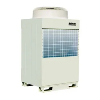
-
Contents
-
Table of Contents
-
Troubleshooting
-
Bookmarks
Quick Links
INSTALLATION, OPERATION & MAINTENANCE MANUAL
Air Cooled Chiller
Models: MAC060/090/120D4
Contents
Related Manuals for McQuay MAC060D4
Summary of Contents for McQuay MAC060D4
- Page 1
INSTALLATION, OPERATION & MAINTENANCE MANUAL Air Cooled Chiller Models: MAC060/090/120D4 Contents… -
Page 2: Table Of Contents
MAC0906-V2 Part No.: M08019320011 1. Introduction Introduction……………………………………………………………………………………………………3 Nomenclature ………………………………………………………………………………………………3 2. Features General Specification………………………………………………………………………………………6 Parameter……………………………………………………………………………………………………7 Performance Chart……………………………………………………………………………………………8 Outlines And Dimensions …………………………………………………………………………………11 Operation Limit………………………………………………………………………………………………13 3. Installation Unit Installation ………………………………………………………………………………………14 Water System Installation ……………………………………………………………………………16 Power Connection …………………………………………………………………………………………20 4. Servicing and Maintenance Servicing and Maintenance ………………………………………………………………………………21 Troubleshooting and Solution ……………………………………………………………………………22 Schematic Diagram ………………………………………………………………………………………27 5.
- Page 3
Installation and maintenance are to be performed only by qualified personnel who are familiar with local codes and regulations, and experienced with this type of equipment. McQuay is not responsible for any unit damage, personal injury or death due to not complying with these requirements. -
Page 4: Introduction
1 Introduction Introduction For years, McQuay international has earned a reputation for providing the industry with various highest quality and most technologically advanced air conditioning systems. Now Shenzhen McQuay is proud to introduce the new generation air-cooled chiller-MAC D series. Inherited from the advantage of the earlier product experiences and introduced the most up-to-date technology, the new MAC D series is designed with the always-in-mind concept — to satisfy customers’…
-
Page 5: Features
Detailed engineering work coupled with extensive market research has resulted the new MAC model come in new mono-block design to yield a compact and robust structure while maintaining the slim outlook. The smaller capacity models MAC060D4 are having side discharge design, while the larger capacity models MAC090/120D4 are having top discharge design.
- Page 6
Safety Control Protection devices such as dual pressure protection and overload protection etc. is provided to ensure unit operating within safety condition range. The microprocessor-based controller automatically directs system on or off by processing the water temperature feedback. If the water temperature falls to unacceptable low point, the controller automatically shut off the system to prevent hydraulic system internal freeze for unit safety operation. -
Page 7: General Specification
General Specification Compressor McQuay Mini Chillers are equipped with highly efficient, reliable and silence scroll compressors for MAC060/090/120D4 Air-Cooler Condenser The air-cooled condenser coil consists of staggered rows of 3/8’’ OD seamless copper tube, mechanically expanded into die formed aluminum fins to ensure optimum heat exchange capability.
-
Page 8: Parameter
Parameter MODEL MAC060D4 MAC090D4 MAC120D4 NOMINAL COOLING CAPACITY 17500 30000 33500 POWER SUPPLY 208-230V/3~/60Hz REFRIGERANT TYPE R407C RATED COOLING POWER INPUT 6000 10100 10600 RATED COOLING CURRENT 18.8 34.7 35.7 TYPE/DRIVE Propeller/Direct FAN MOTOR RATED POWER INPUT 1000 1000 RATED CURRENT…
-
Page 9: Performance Chart
Performance Chart Cooling Capacity Performance Chart MAC060D4 30.0 25.0 20.0 15℃ 12℃ 9℃ 15.0 7℃ 5℃ 10.0 15℃ 20℃ 25℃ 30℃ 35℃ 40℃ 45℃ 48℃ Ambient Temperature(℃) MAC090D4 45.0 40.0 35.0 30.0 15℃ 12℃ 9℃ 25.0 7℃ 5℃ 20.0 15℃…
- Page 10
35.0 12℃ 30.0 9℃ 7℃ 25.0 5℃ 20.0 15℃ 20℃ 25℃ 30℃ 35℃ 40℃ 45℃ 48℃ Ambient Temperature(℃) Cooling Power Input Char MAC060D4 8.50 15℃ 12℃ 7.50 9℃ 7℃ 5℃ 6.50 15℃ 5.50 12℃ 9℃ 7℃ 4.50 5℃ 3.50 15℃… - Page 11
MAC090D4 15℃ 14.00 12℃ 9℃ 13.00 7℃ 12.00 5℃ 11.00 10.00 9.00 8.00 7.00 15℃ 20℃ 25℃ 30℃ 35℃ 40℃ 45℃ 48℃ Ambient Temperature(℃) MAC120D4 15℃ 15.00 12℃ 14.00 9℃ 7℃ 13.00 5℃ 12.00 11.00 10.00 9.00 8.00 7.00 15℃ 20℃… -
Page 12: Outlines And Dimensions
Outlines and Dimensions Model: MAC060D4 4-10X20 2-Rc1 UNIT: mm Model MAC060D4 1212 1700 1135 1162 604.5 ©2009McQuay…
- Page 13
Model: MAC090D4 Fixing Hole 4-14 × 20 4-14 × 20 Fixing Hole Zoom Outlet G Inlet H UNIT: mm Model MAC090D4 Rc1-1/2 Rc1-1/2 MAC120D4 1200 1290 Rc1-1/2 Rc1-1/2 ©2009McQuay… -
Page 14: Operation Limit
Accessory Hydraulic Kit Accessory hydraulic kit consists of 40L capacity stainless steel water storage tank, 8L volume water expansion chamber, safety valve, dirt drainage valve, and auto air vent valve etc. MAC-S1U/M MAC-S4U/M 4-10×20 Chilled Water Inlet N Chilled Water Outlet N Dirt Drainage Port R1/2 151 61 Water Drainage Port DN25…
-
Page 15: Installation
3 Installation Unit Installation The chiller must be installed by qualified company or personnel, which is authorized by McQuay, and the installation must satisfy all the following requirements. Location In order to achieve maximum capacity, the location selection should fulfill the following requirements: The location must be well ventilated, so that air can be drawn in and discharge out efficiently.
- Page 16
7) It is advised to have sufficient clearance around the unit for proper condenser air flow and to facilitate access for maintenance.( see clearance shown in figure below) Back Side >450mm >450mm Front Side guiding device >45 ° >450mm+h1 >450mm+h2 >1000mm >450mm+h3 >100mm+h… -
Page 17: Water System Installation
Water System Installation Chilled water piping must be insulated and waterproof to avoid performance loss and moisture condensing on it. To guarantee the chilled water quality, the water strainer shipped with unit must be installed on the chilled water inlet pipe. Inlet/Outlet Side Panel When performing water pipe connection, use gripping pliers to fix the…
- Page 18
Vmin is referred to the below table: Item Model Setting EWT(℃) Vmin(l) MAC060D4 MAC090D4 MAC120D4 Notice: The total water volume of the entire hydraulic system includes the water in main pipe, water tank and terminal equipment, in which the 2-way valve is open. - Page 19
Unit Water Pressure Drop 1.36 2.44 2.98 3.07 3.47 3.58 3.91 4.61 5.12 5.63 6.08 6.51 7.17 Water Flowrate(m Water Pump Performance Chart Water Flowrate(m ©2009McQuay… - Page 20
Auxiliary heater in the diagram below is available for option, please choose either type of auxiliary electric heater or auxiliary gas heater. If you have the demand, please contact with local McQuay sales representation, and install it according to below diagram, if you have no need of this option, the components in dotted line box can be omitted. -
Page 21: Power Connection
Carry out the electrical connection according to the circuit diagram in unit electrical box so that achieved their automatic on/off governed by the unit controller. In addition, contact with local McQuay service representative for performing trail startup. ©2009McQuay…
-
Page 22: Servicing And Maintenance
There is no need to conduct any maintenance to refrigerant piping if the unit is under normal running. McQuay designers have given full consideration to make servicing convenient during unit development. After opening service panel, both servicing and maintenance can be easily carried out.
-
Page 23: Troubleshooting And Solution
Troubleshooting and Solutions Troubleshooting Displayed on controller and Descriptions Item Code Description Item Code Description compressor overload discharge temperature too high fan overload TH1 malfunction water pump malfunction TH2 malfunction lack of water flow TH3 malfunction high pressure malfunction TH4 malfunction low pressure malfunction TH6 malfunction TH7 malfunction…
- Page 24
Error code and Description Error Code Description Error Code Description Error Code Description ECXX ——- ER30 ——- ER45 TH6 malfunction compressor overload ER31 ——- ER46 TH7 malfunction ER16 suction temperature fan overload ER32 ER47 TH8 malfunction too high discharge ———— ER18 pump overload ER33… - Page 25
Reasons for Malfunction Generating and Solutions Item Error Code Description Reasons Solutions 1. communication cable is A/B connected opposite check communication cable connection 2. communication cable is loose re-do the wiring to avoid power cable and communication cable close; 3. communication cable and power cable is crossed use shield twisted cable communication 4. - Page 26
Item Error Code Description Reasons Solutions 1. motor is damaged(cooling) Change motor; 2. air is short circuit (cooling) improve condenser air circulation; 3. heat exchanger is dirty (cooling) clean condenser 4. refrigerant side filter is dirty check and replace ER20 high pressure (LED) - Page 27
Item Error Code Description Reasons Solutions 1. motor failure(cooling) Change fan motor; 2. return air short circuit (cooling) Improve terminal equipment air circulation; discharge ER33 Clean condenser 3. condenser is dirty (cooling) temperature (LED) 4. EWT is too high re-set EWT by service personal too high 5. -
Page 28: Schematic Diagram
Schematic Diagram MAC060D4 (MAC090/120D4 is two compressors paralleled) Chilled Water In Chilled Water Out LEGEND Refrigerant Fow Direction 2.Heat Exchanger Fan 3.Throttle Device 1.Compressor 5.Water Pump 6.Difference Pressure Switch 4.Bphe 7.Accumulator ©2009McQuay…
-
Page 29: Notice
6) Only clean water is suitable to fill in system, in addition, install the high efficiency water strainer, which is provided by McQuay, on the upstream pipe to unit water inlet 7) Special attention to winter antifreeze During long period shutdown in winter, the water in system must be completely drained out. Please refer to the diagram below and the labels stuck on unit.
- Page 30
While utmost care is taken in ensuring that all details in the publication are correct at the time of going to press, we are constantly striving for improvement and therefore reserve the right to alter model specifications and equipment without notice. Details of specifications and equipment are also subject to change to suit local conditions and requirements and not all models are available in every market.

OM-G11-0104-McQuay
14
11/21/05, 10:49 AM
G11 Remote Controller Indication
Indication De Télécommande G11
G11-Remote-Controller-Anzeige
Indicazioni Telecomando G11
Indicación Del Mando A Distancia G11
Пульт Дистанционного
Управления G11 Индикация
1
2
4
3
6
5
9
10
7
11
8
13
12
14
12
OM-G11-0104-McQuay
i
OM-G11-0104-McQuay
15
11/21/05, 10:49 AM
ii
OM-G11-0104-McQuay
16
11/21/05, 10:49 AM
1
OM-G11-0104-McQuay
1
11/21/05, 10:49 AM
2
OM-G11-0104-McQuay
2
11/21/05, 10:49 AM
OM-G11-0104-McQuay
3
11/21/05, 10:49 AM
4
OM-G11-0104-McQuay
4
11/21/05, 10:49 AM
OM-G11-0104-McQuay
5
11/21/05, 10:49 AM
OM-G11-0104-McQuay
6
11/21/05, 10:49 AM
7
OM-G11-0104-McQuay
7
11/21/05, 10:49 AM
ITALIANO
8
OM-G11-0104-McQuay
8
11/21/05, 10:49 AM
OM-G11-0104-McQuay
9
11/21/05, 10:49 AM
10
OM-G11-0104-McQuay
10
11/21/05, 10:49 AM
1. Источник сигналов
• Источник, откуда сигнал будет передаваться.
2. Индикация передачи сигнала
• Мигает для подтверждения того, что последняя установка была
передана на модуль.
3. Кнопка “ВКЛ/ВЫКЛ” (ON/OFF)
• Нажмите один раз для включения кондиционера.
• Вновь нажмите для остановки модуля.
4. Установка температуры
• Для установки желаемой температуры в комнате, нажмите + или -для повышения или понижения установленной температуры.
• Диапазон установленной температуры варьируется от 16°С до 30°С
(При наличии от 20°С до 30°С).
• Одновременно нажмите обе кнопки для переключения + и -- от
установки °С к °F.
5. Режим работы
• Нажмите кнопку MODE (РЕЖИМ) для выбора типа режима работы.
• Только для охлаждения, возможные режимы: COOL ( ) (ХОЛОД), DRY
( ) (ОСУШЕНИЕ) и FAN ( ) (BЕНТИЛЯЦИЯ).
• Для обогревательного насоса возможные режимы: AUTO ( ) (АВТО),
COOL ( ) (ХОЛОД), DRY ( ) (ОСУШЕНИЕ), FAN ( ) (ВЕНТИЛЯЦИЯ)
и HEAT ( ) (ОБОГРЕВ).
6. Выбор скорости вентилятора
• Нажмите кнопку для непрерывного переключения скорости
вентилятора в следующем порядке:
Низк –––: Сред –––: Высок –––: Авто
• Прекратите нажимание, как только на дисплее экрана появится
желаемая скорость вентилятора.
7. Функция турбо
• Нажмите для быстрого охлаждения или операции обогрева.
• Температура повышается в комнате при режиме HEAT (ОБОГРЕВ),
понижается при режиме COOL (ХОЛОД) или DRY (ОСУШЕНИЕ).
Скорость вентилятора повысится, если он не установлен на
максимальную скорость.
• Температура и скорость вентилятора вернутся на установленное
функционирование при повторном нажатии или после 20 минут.
• Возможны только при режимах HEAT (ОБОГРЕВ), COOL (ХОЛОД) и
DRY (ОСУШЕНИЕ).
8. Установка включения таймера
• Нажмите кнопку SET для запуска функции включения таймера.
• Установите желаемое время включения беспрерывным нажатием
кнопки SET. Если таймер установлен на 7:30 утра, то кондиционер
включится ровно в 7:30 утра.
11
OM-G11-0104-McQuay
11
11/21/05, 10:49 AM
РУCCKИЙ
РУКОВОДСТВО ПО ИСПОЛЬЗОВАНИЮ
• Нажмите кнопку СLR для отмены установки включения таймера.
9. Установка выключения таймера
• Нажмите кнопку SET для запуска функции выключения таймера.
• Установите желаемое время выключения беспрерывным нажатием
кнопки SET.
• Нажмите кнопку СLR для отмены установки выключения таймера.
10. Автоматический поворот направления жалюзи (при наличии)
• Нажмите кнопку SWING (ПОВОРОТ) для включения функции
автоматического поворота жалюзи.
• Для распространения воздуха в определенном направлении, нажмите
кнопку SWING (ПОВОРОТ) и ждите до тех пор, пока жалюзи не
установится в желаемом направлении, и вновь нажмите кнопку один раз.
11. Установка режима сна
• Нажмите кнопку SLEEP (СОН) для включения функции режима сна.
• Эта опция служит для энергосбережения. При работе модуля в
режиме охлаждения, установленная
температура повышается на 0,5°С
+2 C
после первого получаса, на 1°С после
следующего получаса и в сумме на 2°С +1 C
после следующего 1 часа. Эта функция
предотвращает от чрезмерного
охлаждения в течение летнего
-1C
периода времени.
• При работе модуля в режиме обогрева, - 2 C
0
0,5
1
1,5
2
установленная
температура
понижается на 1°С после первого
получаса, на 2°С после следующего получаса и в сумме на 3°С после
следующего 1 часа. Эта функция предотвращает от ночного
перегрева в течение летнего периода времени.
• Эта функция возможна в режимах COOL (ХОЛОД), HEAT
(ОБОГРЕВ) и AUTO (АВТО).
12. Установка времени часов
• Нажмите + для увеличения времени часов.
• Нажмите -- для уменьшения времени часов.
13. Персонализация
• Нажмите кнопку и удерживайте ее 3 сек, начнет мигать индикатор
. Нажмите еще раз для переключения между и .
• Установите требуемый параметр, после чего не нажимайте никакие
кнопки в течение 4 сек. Параметр будет сохранено в программе.
• Нажмите кнопку один раз для активации параметра P1; нажмите
еще раз для переключения между P1 и P2.
• Нажмите любую кнопку для отключения персонализации.
14. Ионизатор (дополнительно)
• Для активации функции ионизатора нажмите кнопку .
• Для отключения данной функции нажмите эту кнопку еще раз.
12
OM-G11-0104-McQuay
12
11/21/05, 10:49 AM
MEMO / LE MÉMO / MITTEILUNG / PROMEMORIA /
EL MEMORÁNDUM / ПАМЯТКА
memo
1
12/20/05, 11:06 AM
MEMO / LE MÉMO / MITTEILUNG / PROMEMORIA /
EL MEMORÁNDUM / ПАМЯТКА
memo
1
12/20/05, 11:06 AM
•
•
•
•
•
•
•
•
•
•
•
В случае противоречия перевода данного руководства с другими переводами одного и того же
текста, английский вариант рассматривается как приоритетный.
•
Завод-изготовитель оставляет за собой право изменять характеристики и конструкцию в любое
время без предварительного уведомления.
OM-G11-0104-McQuay
13
11/21/05, 10:49 AM
VOd²« VO²
r—
JANUARY 2004 ¥ a¹—Uð
Æq³I²LK lłdL tÐ ÿUH²Šô«Ë W¹UMFÐ «c¼
ULOKF²« VO² …¡«d vłd¹ ¨¡«uN« WHOJ ‰ULF²Ý« q³
OM-G11-0104-McQuay_AR
2
11/25/05, 6:10 PM
G11 bFÐ sŽ rJײ« ÕU²H …—Uý«
±
1
≤2
¥
4
≥
3
∑7
∂
6
±±
11
∏8
±≥
13
±≤
12
±¥
14
µ
5
π
9
±∞
10
W O Ðd F «
±≤
12
OM-G11-0104-McQuay
i
OM-G11-0104-McQuay_AR
1
11/25/05, 6:10 PM
—«b'« vKŽ XO³¦²« WOHO
U¹—UD³« ‰Ušœ≈
ii
2
13/1/2004, 6:00 PM
qOGA²« qOœ
‰UÝ—ô« —bB Ʊ
ÆtÐ …—Uýô« qI½ r²¹ Íc« —bB*«
•
Æ…bŠuK UNKI½ - b …dOšô« W¾ON²« ÊQÐ bOu² iuð
•
…—Uýô« ‰UÝ—« WöŽ Æ≤
“ON/OFF” —“
•
•
Æ¡«uN« WHOJ qOGA² …bŠ«Ë …d jG{«
Æ…bŠu« ·UI¹ô Èdš« …d jG{«
Æ≥
…—«d(« Wł—œ W¾ONð Æ¥
ÆWÞu³C*« …—«d(« Wł—œ qOKIð Ë« …œU¹e -- Ë« + —“ jG{« ¨WdGK WÐužd*« …—«d(« Wł—œ j³C
©Æ°≥∞ v« °≤∞ s W¹—UO²šô« W¾ON²«® Æ°≥∞ v« °±∂ 5ÐU …—«d(« Wł—œ Èb ÕË«d²¹
Æ°F v« °C s -- Ë + q¹uײ bŠ«Ë ʬ w ULNOK s¹—e« jG{«
•
•
•
qOGA²« l{Ë Æµ
Ë FAN (
Æ FAN ( ) Ë DRY (
) ¨DRY ( ) ¨COOL (
ÆqOGA²« l{Ë Ÿu½ —UO²šô MODE —“ jG{«
) ¨COOL ( ) ∫w¼ …du²*« ŸU{Ëô« Ê« ¨jI b¹d³²« …bŠu
) ¨AUTO ( ) ∫w?¼ …d?u?²?*« ŸU?{Ëô« ¨W?¾?b?²?« a{ …bŠu
ÆHEAT ( )
•
•
•
ÆwU²« VOðd²UÐ WŠËd*« WŽdÝ q¹uײ —«dL²ÝUÐ —“ jG{«
wzUIKð ;––– wUŽ ;––– jÝu² ;––– iHM
ÆWýUA« W{—UŽ vKŽ WŠËd*« WŽdÝ dNEð UbMŽ jGC« sŽ nuð
•
•
WOMOÐd²« WHOþu« Æ∑
ÆW¾b²« qOGAð Ë« l¹d« b¹d³²K jG{«
Ë« COOL l{Ë w X½U «–« qIðË ¨HEAT l{Ë w WHOJ*« X½U «–« WOKš«b« …—«d(« Wł—œ œ«œeð ·uÝ
ÆDRY
ÆÈuBI« UN²ŽdÝ w sJð r «–« WŠËd*« WŽdÝ œ«œeð ·uÝ
≤∞ —Ëd bFÐ Ë« Èdš« …d —“ XDG{ «–« Âb²*« W¾ONð v« WŠËd*« WŽdÝË …—«d(« Wł—œ …œUŽ« r²ð ·uÝ
ÆWIOœ
ÆjI DRY Ë COOL Ë HEAT ŸU{Ë« w du²¹
•
•
•
•
ON XR W¾ONð
ÆqOGA²« XR WHOþË jOAM² SET —e« jG{«
·uÝ ¨ÎU?ŠU³ 7.30 v?K?Ž X?R*« j³{ - «–« ÆSET —“ j?G?C?Ð —«d?L?²?ÝôUÐ »užd*« qOGA²« XË j³{«
Æj³CUÐ UŠU³
Î
7.30 WŽU« w ¡«uN« WHOJ qG²Að
ÆqOGA²« XR W¾ONð ¡UGô CLR —e« jG{«
±
3
13/1/2004, 6:00 PM
•
•
•
Æ∏
OFF XR W¾ONð
•
•
Æ·UI¹ô« XR WHOþË jOAM² SET —e« jG{«
ÆSET —“ jGCÐ —«dL²ÝôUÐ »užd*« ·UI¹ô« XË j³{«
Æ·UI¹ô« XR W¾ONð ¡UGô CLR —“ jG{«
Æπ
•
©Í—UO²š«® ¡«uNK wzUIK²« Ê«—Ëb« Ʊ∞
Æ¡«uN« Ê«—Ëœ WHOþË jOAM² SWING —“ jG{«
—e?« jG{«Ë »užd*« ÁU&ôUÐ oA« „dײ¹ Ê« v« dE²½«Ë SWING —“ j?G{« ¨5F ÁU&UÐ ¡«uN« l¹“u²
ÆÈdš« …d
•
•
ÆÂuM« l{Ë WHOþË jOAM² SLEEP —“ jG{«
X?% …b?Šu?« q?G?²?A?ð U?b?MŽ ÆWUDUÐ œUB²ô« —UOš u¼ «c¼
b?FР°∞[µ ‡?Ð W?Þu?³?C?*« …—«d?(« Wł—œ œ«œeð ¨b¹d³²« l{Ë
WŽU« s w½U¦« nBM« bFР°± ¨WŽU« s ‰Ëô« nBM«
◊«dô« s WHOþu« Ác¼ lM9 ÆWOU²« WŽU« bFР°≤ ŸuL−Ë
ÆnOB« qB ¡UMŁ« b¹d³²UÐ
…—«d?(« W?ł—œ q?I?ð ¨W?¾?b?²?« l?{Ë X?% …b?Šu?« qOGAð bMŽ
b?FР°≤ Ë ¨W?ŽU??« s? ‰Ëô« n?BM« bFР°± ‡?Ð W?Þu?³C*«
v?Ëô« WŽU« bFР°≥ Ÿu?L?:«Ë W?ŽU?« s w½U¦« nBM«
¡U?M?Ł√ q?O?K?« w? Àb?×?¹ Íc?« ‚d?F?²?« lM* WHOþu« Ác¼ ÆWOU²«
ÆnOB« qB
ÆAUTO Ë HEAT ¨COOL l{Ë X% WHOþu« Ác¼ du²ð
+2 C
+1 C
-1C
-2C
0
0,5
1
1,5
2
•
•
•
•
WŽU« XË W¾ONð Ʊ≤
ÆWŽU« XË …œU¹e + —e« jG{«
ÆWŽU« XË qOKI² -- —e« jG{«
•
•
WOBA« W¾ON²« Ʊ≥
Æ Ë 5Ð Ê«—ËbK Èdš√ …d
Î jG{« ¨ WöF« iuð rŁ ¨w½«uŁ ≥ …b* ÎUÞuGC tÐ kH²Š«Ë jG{«
w W¾ON²« kHŠ r²¹ ·uÝË ÕU²H Í√ jG{ ÊËœ s w½«uŁ ¥ …b* ÍËbO« “UN'« „dð« rŁ ¨WÐužd*« W¾ON²« j³{«
ÆZU½d³«
ÆP2 Ë P1 5Ð Ê«—ËbK Èdš√ …d jG{« rŁ ¨ P1 W¾ONð jOAM² jG{«
ÆWOBA« W¾ON²« qODF² ÕU²H Í« jG{«
•
•
•
•
©W¹—UO²š«® s¹R*« W¾ONð Ʊ¥
4
13/1/2004, 6:00 PM
•
•
Æs¹R*« WHOþË jOAM² jG{«
ÆWHOþu« qODF² Èdš« …d jG{«
Æ…bzU« w¼ W¹eOKJ½ô« WM« ÊuJð ¨X½U WG W¹QÐ UNH½ WLłd²« w ·ö²š« Í«Ë VO²J« «c¼ dOHð w ÷—UFð Í« ÀbŠ «–«
Æo³ —UFý≈ ÊËœ s XË Í« w UM¼ …œułu
OM-G6W-0501-McQuay_AR
2
UH«u W¹«Ë rOLB²« q¹bFð o×Ð lMB*« kH²×¹
11/28/05, 3:25 PM
•
•