-
Contents
-
Table of Contents
-
Bookmarks
Quick Links
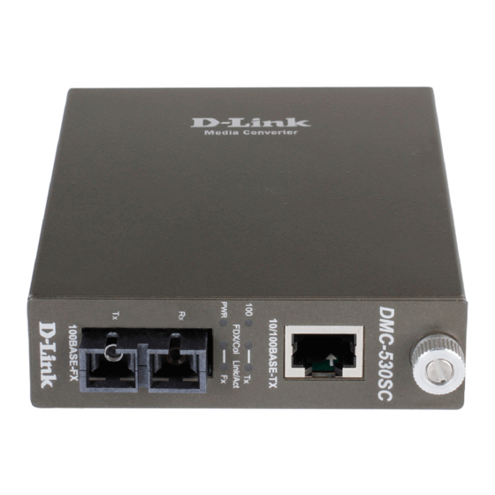
10/100BASE-TX to
100BASE-FX
Media Converter
User’s Guide
Rev. 01 (JUN. 2002)
1907M110MM16003
RECYCLABLE
Related Manuals for D-Link 10/100BASE-TX to 100BASE-FX Media Converter
Summary of Contents for D-Link 10/100BASE-TX to 100BASE-FX Media Converter
-
Page 1: Media Converter
10/100BASE-TX to 100BASE-FX Media Converter User’s Guide Rev. 01 (JUN. 2002) 1907M110MM16003 RECYCLABLE…
-
Page 2: Table Of Contents
TABLE ONTENTS TABLE OF CONTENTS ..2 INTRODUCTION ….3 ……..3 BOUT EDIA ONVERTER ……….3 RODUCT EATURES INSTALLATION ….4 ….4 ELECTING A ITE FOR THE QUIPMENT ………5 ONNECTING TO OWER …………5 LIDING WITCH ………6 ONNECTING TO OWER ……..6 NSTALLING IN A HASSIS LED I …………7 NDICATOR…
-
Page 3: Introduction
NTRODUCTION Thank you for choosing the 10/100BASE Fast Ethernet Media Converter, The Converter introduced here provides one channel media conversion between 10/100BASE-TX and 100BASE-FX. About Media Converter The Media Converter is a network technology specified by IEEE 802.3 10BASE-T, IEEE802.3u 100BASE-TX, 100BASE-FX standards.
-
Page 4: Installation
NSTALLATION This chapter gives step-by-step installation instructions for the Converter. Selecting a Site for the Equipment As with any electric device, you should place the equipment where it will not be subjected to extreme temperatures, humidity, or electromagnetic interference. Specifically, the site you select should meet the following requirements: The ambient temperature should be between 32 and 104 degrees Fahrenheit (0 to 40 degrees…
-
Page 5: Connecting To Power
Connecting to Power This Converter is a plug-and-play device. Connect the supplied AC to DC power adaptor with a power voltage of 7.5Vdc/1.5Amp to the receptacle on the rear panel of the converter, and then attach the plug into a standard AC outlet with a voltage range from 100 to 260 Vac.
-
Page 6: Connecting To Power
Connecting to Power This Converter is a plug-and-play device. Connect the supplied AC to DC power adaptor with a power voltage of 7.5Vdc/1.5Amp to the DC-Jack on the converter, and then attach the plug into a standard AC outlet Installing in a Chassis The Converter can be fit into any of the expansion slots on a special designed chassis.
-
Page 7: Led Indicator
LED Indicator The LED indicators give you instant feedback on status of the converter: LEDs State Indication Power Steady Power on (PWR) Power off 100 Mbps Steady Runs at 100Mbps on TX port (100) Runs at 10Mbps on TX port Steady Connection in full duplex (FDX)
-
Page 8: Specifications
PECIFICATIONS Applicable IEEE 802.3 10BASE-T Standards IEEE802.3u 100BASE-TX & 100BASE-FX Fixed Ports 1 TX port, 1 FX port Speed 10/20Mbps for half/full-duplex 100/200Mbps for half/full-duplex Forwarding 148,800pps rate LED Indicators Per Unit- (2 LEDs): Power; Speed( 100 ) Per Port- (2 LEDs): FDX/COL, LINK/ACT Cable 10BASE-T –…
-
Contents
-
Table of Contents
-
Troubleshooting
-
Bookmarks
Quick Links
User’s Manual
FST-801
FST-802
FST-802S15/802S35/802S50
FST-806A20/806B20
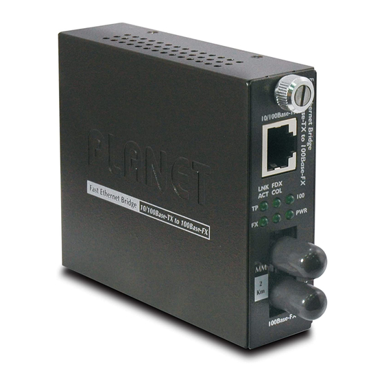
10/100Base-TX to 100Base-FX
Smart Media Converter
— 1 —
Related Manuals for Planet FST-801
Summary of Contents for Planet FST-801
-
Page 1
User’s Manual FST-801 FST-802 FST-802S15/802S35/802S50 FST-806A20/806B20 10/100Base-TX to 100Base-FX Smart Media Converter — 1 -… -
Page 2: Fcc Warning
Trademarks Copyright © PLANET Technology Corp. 2010 Contents subject to revision without prior notice. PLANET is a registered trademark of PLANET Technology Corp. All other trademarks belong to their respective owners. Disclaimer PLANET Technology does not warrant that the hardware will work properly in all environments and applications, and makes no warranty and representation, either implied or expressed, with respect to the quality, performance, merchantability, or fitness for a particular purpose.
-
Page 3: Table Of Contents
TABLE OF CONTENTS 1. INTRODUCTION …………………………4 1.1 C …………………………..4 HECKLIST 1.2 A 10/100B 100B -FX S …………. 4 BOUT THE MART EDIA ONVERTER 1.3 F …………………………… 4 EATURES 1.4 S …………………………..5 PECIFICATION 1.5 P …………………………6 RODUCT UTLOOK 2.
-
Page 4: Introduction
1. INTRODUCTION 1.1 Checklist Thank you for purchasing PLANET 10/100Base-TX to 100Base-FX Smart Media Converter, the 10/100Base-TX to 100Base-FX Smart Media Converter package shall contain following contents: Check the contents of your package for following parts: 10/100Base-TX to 100Base-FX Smart Media Converter x1 User’s manual CD x1 DC 5V 2A Power Adapter x1 If any of these pieces are missing or damaged, please contact your dealer immediately, if possible, retain the carton…
-
Page 5: Specification
1.4 Specification Model FST-801 FST-802 FST-802S15 FST-802S35 FST-802S50 FST-806A20 FST-806B20 Hardware Specification Standards IEEE 802.3 10Base-T, IEEE 802.3u 100Base-TX and 100Base-FX Ports 1 10/100Base-TX port , 1 100Base-FX port Fiber connector SC, WDM SC, WDM Wavelength 1310nm (Transmit and Receive)
-
Page 6: Product Outlook
1.5 Product Outlook Right View: there is one RJ-45 twisted-Pair jack (Auto-MDI/MDI-X), one fiber-optic connector (vary by model) and six LED indicators. Left View: there is one DC jack for DC 5V power adapter. 10/100Base-TX FDX Fast Ethernet Bridge 10/100Base-TX to 100Base-FX 100Base-FX LED Indicators Color…
-
Page 7: Hardware Installation
2. HARDWARE INSTALLATION This product provides two different running speeds – 10/100Base-TX and 100Base-FX in the same device and the 10/100Base-TX RJ-45 port can automatically distinguish the speed of incoming connection. This section describes the hardware installation of FST-80x. Before connecting any network device to the FST-80x, read this chapter carefully.
-
Page 8: Slide Media Converter Module Into Mc-1600Mr/R48 Chassis Installation
2.2 Slide Media Converter module into MC-1600MR/R48 Chassis installation Step 1- Unscrew and pull out the FST-80x Media Converter board. Step 2- Remove a blank faceplate from an empty expansion slot on the front of the chassis. The FST-80x Media Converter board can be installed in any expansion slot.
-
Page 9: Real Ethernet Environment Application
2.3 Real Ethernet environment application Standalone and centralize management Media Converter installation Afford the current network grows and expanding, the PLANET FST-80x provide advanced Media conversion technology to fill this kind of demand. The FST-80x provide the diverse fiber connect type options to meet different network application, it is very flexible for FST-80x work as a standalone devices or install into the central Web Smart Media converter chassis for centralize management.
-
Page 10: Manage The Media Converter
3. MANAGE THE MEDIA CONVERTER This product provides two different managed methods – configure through its DIP Switch or install into the central Web Smart Media converter chassis for centralize management. This section describes how to managed the FST-80x through its DIP Switch and Web Smart Media converter chassis. Before use the FST-80x smart function, please read this chapter carefully.
-
Page 11: Managed Media Converter Module Through Mc-1600Mr/R48 Chassis
3.2 Managed Media Converter module through MC-1600MR/R48 Chassis The Web Smart Media Coverter Chassis that can control FST-80X through the management system,FST-80X can be controlled through Web Browser and terminal emulation program. The Web Smart Media Converter Chassis will display out the status of FST-80x, also the Web Smart Media Coverter Chassis can control the function through the management system.
-
Page 12: Link Pass Through Function
4. LINK PASS THROUGH FUNCTION The LFP function includes the Link Fault Pass Through function (LLCF/LLR) and the DIP Switch design. LLCF/LLR can immediately alarm administrators the problem of the link media and provide efficient solution to monitor the net. The DIP Switch provides disable or enable the LFP function.
-
Page 13: Link Loss Return (Llr)
4.2 Link Loss Return (LLR) The fiber ports of FST-80X have been designed with an LLR function for troubleshooting a remote connection. LLR works in conjunction with LLCF. When LLR is enabled*, the port’s transmitter shuts down when its receiver fails to detect a valid receive link. LLR should only be enabled on one end of the link and is typically enabled on either the unmanaged or remote device.
-
Page 14: Troubleshooting
5. TROUBLESHOOTING This chapter contains information to help you solve issues. If the FST-80x is not functioning properly, make sure the FST-80x was set up according to instructions in this manual. The Power LED is not lit Solution: Check the power cable connection between power adapter and FST-80X. Why I connect FST-80x to device with 100Base-FX interface and the 100Base-FX fiber connection fail? Solution: Please check the fiber connection between two devices is correct.
-
Page 15: Appendix A Networking Connection
APPENDIX A NETWORKING CONNECTION A.1 Switch‘s RJ-45 Pin Assignments 10/100Mbps, 10/100Base-TX RJ-45 Connector pin assignment Contact MDI-X Media Dependant Media Dependant Interface Interface -Cross Tx + (transmit) Rx + (receive) Tx — (transmit) Rx — (receive) Rx + (receive) Tx + (transmit) 4, 5 Not used Rx — (receive)
-
Page 16: Cable Connection Parameter
A.3 Cable Connection Parameter The limitations are shown as below; Duplex Connection Limitation (max.) Twisted Pair Half / Full Node to Node 100 meters Node to Switch/ Hub Multi-Mode Converters MM Half Node to Node 412 meters Node to Switch MM Full Node to Node 2 kilometers…
-
Page 17: Ec Declaration Of Conformity
: FST-806A20/B20 * Produced by: Manufacturer‘s Name : Planet Technology Corp. Manufacturer‘s Address : 11F, No. 96, Min Chuan Road, Hsin Tien Taipei, Taiwan , R. O.C. is herewith confirmed to comply with the requirements set out in the Council Directive on the Approximation of the Laws of the Member States relating to Electromagnetic Compatibility Directive on (89/336/EEC).
-
Page 18
: FST-802S15_S35_S50 * Produced by: Manufacturer‘s Name : Planet Technology Corp. Manufacturer‘s Address : 11F, No. 96, Min Chuan Road, Hsin Tien Taipei, Taiwan , R. O.C. is herewith confirmed to comply with the requirements set out in the Council Directive on the Approximation of the Laws of the Member States relating to Electromagnetic Compatibility Directive on (89/336/EEC). -
Page 19
: FST-801_802 * Produced by: Manufacturer‘s Name : Planet Technology Corp. Manufacturer‘s Address : 11F, No. 96, Min Chuan Road, Hsin Tien Taipei, Taiwan , R. O.C. is herewith confirmed to comply with the requirements set out in the Council Directive on the Approximation of the Laws of the Member States relating to Electromagnetic Compatibility Directive on (89/336/EEC).
![]() 100Base-FX to 10/100Base-TX PoE Media Converter
100Base-FX to 10/100Base-TX PoE Media Converter
User Manual 
100Base-FX to 10/100Base-TX PoE
Media Converter
FCU-1802Px User’s Manual
100Base-FX to 10/100Base-TX PoE Media Converter
Trademarks
Copyright © Antaira Technologies 2013.
Contents are subject to revision without prior notice.
Antaira is a registered trademark of Antaira Technologies. The information in this manual is subject to change without notice. All other trademarks belong to their respective owners.
Disclaimer
Antaira Technologies does not warrant that the hardware will work properly in all environments and applications, and makes no warranty and representation, either implied or expressed, with respect to the quality, performance, merchantability, or fitness for a particular purpose.
Antaira has made every effort to ensure that this User’s Manual is accurate; Antaira disclaims liability for any inaccuracies or omissions that may have occurred.
Information in this User’s Manual is subject to change without notice and does not represent a commitment on the part of Antaira. Antaira assumes no responsibility for any inaccuracies that may be contained in this User’s Manual. Antaira makes no commitment to update or keep current the information in this User’s Manual and reserves the right to make improvements to this User’s Manual and/or to the products described in this User’s Manual, at any time without notice.
If you find information in this manual that is incorrect, misleading, or incomplete, we would appreciate your comments and suggestions.
FCC Warning
This equipment has been tested and found to comply with the regulations for a Class A digital device, pursuant to Part 15 of the FCC Rules. These limits are designed to provide reasonable protection against harmful interference when the equipment is operated in a commercial environment. This equipment generates, uses, and can radiate radio frequency energy and, if not installed and used in accordance with this user’s guide, may cause harmful interference to radio communications. Operation of this equipment in a residential area is likely to cause harmful interference, in which case the user will be required to correct the interference at his own expense.
CE Mark Warning
This is a Class A product. In a domestic environment, this product may cause radio interference, in which case the user may be required to take adequate measures.
Energy Saving Note of the Device
This power-required device does not support Standby mode operation.
For energy saving, please remove the DC plug or push the hardware Power Switch to the OFF position to disconnect the device from the power circuit.
Without removing the DC-Plug or switching to OFF, the device will still consume power from the power source. In view of Saving Energy and reducing unnecessary power consumption, it is strongly suggested to power off or to remove the DC plug for the device if this device is not intended to be active.
WEEE Warning![]() To avoid the potential effects on the environment and human health as a result of the presence of hazardous substances in electrical and electronic equipment, end users of electrical and electronic equipment should understand the meaning of the crossed-out wheeled bin symbol. Do not dispose of WEEE as unsorted municipal waste and have to collect such WEEE separately.
To avoid the potential effects on the environment and human health as a result of the presence of hazardous substances in electrical and electronic equipment, end users of electrical and electronic equipment should understand the meaning of the crossed-out wheeled bin symbol. Do not dispose of WEEE as unsorted municipal waste and have to collect such WEEE separately.
Revision
User’s manual for Antaira 100Base-FX to 10/100Base-TX PoE Media Converter
Rev 1.1 (April 2013)
Part No. 2350-AA3540-470
Overview
Thank you for purchasing Antaira’s FCU-1802Px family of 10/100Mbps Ethernet Twisted pair to 100Base-FX Fiber-optic PoE Bridge Converter. This converter is used to convert one type of media signal to another easily, efficiently, and inexpensively. The converter provides Power over Ethernet power injector function which is able to drive one IEEE 802.3af compliant powered device.
About the Power over Ethernet Injector
The FCU-1802Px has an IEEE 802.3af Power over Ethernet Injector that provides DC 48V over Ethernet cables. The FCU-1802Px IEEE 802.3af Power over Ethernet Injector inserts DC Voltage into Cat.5 cable, allowing the cable between the Injector (FCU-1802Px) and PoE PD (Powered Device) to transfer data and power simultaneously. The maximum distance between the Injector (FCU-1802Px) and PoE PD is 100 meters. With the FCU-1802Px installed, it combines the Ethernet digital data with power over the twisted pair cables as an IEEE 802.3af Power over Ethernet Injector. And the IEEE 802.3af Power over Ethernet splitter shall separate the digital data and the power into two outputs.
With IEEE 802.3af Power over Ethernet devices installed, the system administrator only has to use a single RJ-45 Ethernet cable to carriy both power and data to each device. Aside from connecting through the FCU-1802Px and PoE PD, you can also have the benefit of cost saving, easy for networking planning, and higher reliability. Moreover, upon any IEEE 802.3af device installation, the FCU-1802Px or PD can make the connection while migrating the Ethernet digital packets, such as connecting the FCU-1802Px to an IEEE 802.3af complied devices, AP or IP Camera.
Checklist
Your FCU-1802Px package should contain the following items:
- 100Base-FX to 10/100Base-TX PoE Media Converter x 1
- AC-DC Power Adapter (Input: 48V DC, 0.4A max.) x 1
- User’s Manual x 1
- If any items are missing or damaged, please consult the dealer from which you purchased your PoE Media Converter.
Product Outlook
Overview
The layout of the FCU-1802Px.

Left View
There is one RJ-45 Twisted-Pair jack (Auto-MDI/MDI-X), one fiber-optic connector (vary by model) and four LED indicators.
Right View
One DIP switch for Link Fault Pass Through (LFP) feature, “ON” to turn-on the LLCF and LLR detection. And “OFF” to turn off this feature. Please refer to the following sections for more. Also one DC 48V power socket for the PoE Media Converter.
Link Fault Pass-through (LFP)
The LFP function includes the Link Fault Pass Through function (LLCF/LLR) and the DIP Switch design. LLC/LLR can immediately alert administrators about problems with the link media and provide an efficient solution to monitor the net. The DIP Switch can disable or enable the LFP function.
With LLCF (Link Loss Carry Forward), when a device connected to the converter loses the TP line link, the converter’s fiber will disconnect the link of transmitting. With LLR (Link Loss Return), when a device is connected to the converter and loses the fiber line link, the converter’s fiber will disconnect the link of transmitting. Both can immediately alert administrators about link media problems and provide an efficient solution to monitor the net.
Link Loss Carry Forward (LLCF)
The FCU-1802Px incorporates an LLCF function for troubleshooting a remote connection. When the LFP function is enabled, the FL/TP ports do not transmit a link signal until they receive a link signal from the opposite port.
The diagram below shows a typical network configuration with a good link status using the FCU-1802Px for remote connectivity. If the connection breaks, the FCU-1802Px link loss forwards to the switch/hub which generates a trap to the management station. The administrator can then determine the source of the problem.
*Units are shipped with the LFP function disable (OFF).
Link Loss Return (LLR)
The fiber ports of the FCU-1802Px have been designed with an LLR function for troubleshooting a remote connection. LLR works in conjunction with LLC.
When the LFP function is enabled, the port’s transmitter shuts down when its receiver fails to detect a valid receive link. LLR should only be enabled on one end of the link and is typically enabled on either the unmanaged or remote device.
The diagram below shows a typical network configuration with a good link status using the FCU-1802Px for remote connectivity. Note that LLR and LLCF are enabled as indicated in the diagram. If one of the optical conductors is bad (as shown in the diagram box below), the converter with the LLR function will return a no-link condition to its link partner. With LLC function also enabled, the no-link condition is carried forward to the switch/hub where a trap is generated to the management station, and the administrator can then determine the source of the loss.
![]() Note
Note
The LFP function is turned on by default. This feature can also be turned off via the side DIP switch. If you are familiar with the network installation, for diagnostic purposes (i.e. check which end is broken), you can turn it off and reset the converter to make it take effect. Otherwise, please leave it at the default position.
Installing the Converter
Please follow these steps to install the PoE Media converter:
- Turn off the power of the device/station on the network to which the FCU-1802Px will be attached.
- Ensure that there is no activity in the network.
- Attach fiber cable from the FCU-1802Px to the fiber network. TX and RX must be paired at both ends. Attach a Cat. 5 UTP cable from the 10/100Base-TX network to
the RJ-45 port on the FCU-1802Px. - Connect the 48V DC power adapter to the FCU-1802Px and verify that the Power LED is lit.
- Turn on the power of the device/station, and the TX Link, and FX Link LEDs should light when all cables are attached.

![]() Note
Note
RJ-45/STP, UTP Cat 5, straight /crossover cable is accepted.
Please refer to section 9 for more about the wiring distance of your TP, Optic-fiber networks.
PoE function
FCU-1802Px and the IEEE 802.3af Injector / Splitter equipment installation: Before your installation, it is recommended to check your network environment. If there is any IEEE 802.3af devices that need to power on, the FCU-1802Px can provide a way to supply power for this Ethernet device conveniently and easily. The FCU-1802Px comes with an AC-DC adapter with DC 48V input and injects this DC power into the pin of the twisted pair cable (pair 1, 2 and pair 3, 6).
 LED indication
 LED indication
· System
| LED | Color | Function |
| PWR | Green | Lit: Indicate the device is powered. |
· 10/100Base-TX Port
| LED | Color |
Function |
|
| LNK/ACT | Green |
Blink |
Indicate that the Media Converter is actively sending or receiving data over that port. |
| Lit | Indicate that the port is linked up. | ||
| Off | Indicate that the port is linked down. | ||
| PoE in Use | Green |
Lit |
Indicate that the port is providing 48VDC to the remote-powered devices. |
|
Off |
Indicate that the port is not providing 48VDC to the remote-powered devices. |
· 100Base-FX SC Port
| LED | Color |
Function |
|
| LNK/ACT |
Green |
Blink | Indicate that the Media Converter is actively sending or receiving data over that port. |
| Lit | Indicate that the port is linked up. | ||
| Off | Indicate that the port is linked down. |
· System · 10/100Base-TX Port Function Blink Lit Off · 100Base-FX SC Port Function Green The FCU-1802Px comes with the following standard features: Connecting to Router, Bridge, or Switch, or Hub, please refer to the device’s Technical Manual. APPENDIX A A.1 Device’s RJ-45 Pin Assignments MDI-X Implicit implementation of the crossover function within a twisted-pair cable, or at a wiring panel, while not expressly forbidden, is beyond the scope of this standard. There are 8 wires on a standard UTP/STP cable and each wire is color-coded. The following shows the pin allocation and color of straight cable and crossover cable connection:![]() LED indication
LED indication
LED
Color
Function
PWR
Green
Lit: Indicate the device is powered.
LED
Color
LNK/ACT
Green
Indicate that the Media Converter is actively sending or receiving data over that port.
Lit
Indicate that the port is linked up.
Off
Indicate that the port is linked down.
PoE in Use
Green
Indicate that the port is providing 48VDC to the remote-powered devices.
Indicate that the port is not providing 48VDC to the remote-powered devices.
LED
Color
LNK/ACT
Blink
Indicate that the Media Converter is actively sending or receiving data over that port.
Lit
Indicate that the port is linked up.
Off
Indicate that the port is linked down.
![]() Note
Note
Fiber-optic Partner should be set to the correct mode according to this FDX indicator for optimal network performance.Cable Connection Parameter
Duplex
Connection
Limitation (max.)
Twisted Pair
Half / Full
Node to Node
Node to Switch/Hub100 meters
Multi-Mode Converters
MM Half
Node to Node
Node to Switch412 meters
MM Full
Node to Node
Node to Switch2 kilometers
Single-Mode Converters
SM Full
Node to Node
Node to Switch15 kilometers
FCU-1802Px Technical Specifications
· 10/100Mbps, 10/100Base-TX
Contact
MDI
1
1 (TX +)
3
2
2 (TX -)
6
3
3 (RX +)
1
6
6 (RX -)
2
4, 5, 7, 8
Not used
Not used
A.2 RJ-45 cable pin assignment
Straight Cable
There are 8 wires on a standard UTP/STP cable and each wire is color-coded. The following shows the pin allocation and color of straight cable and crossover cable connection:
Straight Cable
| SIDE 1 1 = White/Orange 2 = Orange 3 = White/Green 4 = Blue 5 = White/Blue 6 = Green 7 = White/Brown 8 = Brown |
SIDE 2 1 = White/Orange 2 = Orange 3 = White/Green 4 = Blue 5 = White/Blue 6 = Green 7 = White/Brown 8 = Brown |
Cross Over Cable
| SIDE 1 1 = White/Orange 2 = Orange 3 = White/Green 4 = Blue 5 = White/Blue 6 = Green 7 = White/Brown 8 = Brown |
SIDE 2 1 = White/Orange 2 = Orange 3 = White/Green 4 = Blue 5 = White/Blue 6 = Green 7 = White/Brown 8 = Brown |
Figure A-1: Straight-Through and Crossover Cable
Please make sure your connected cables are with the same pin assignment and color as the above picture before deploying the cables into your network.
A.3 Fiber Optical Cable Connection Parameter
The wiring details are as below:
· Fiber Optical patch Cables:
| Standard | Fiber Type | Cable Specification |
| 100Base-FX (1310nm) | Multi-mode | 50/125μm or 62.5/125μm |
| 100Base-FX (1310nm) | Single-mode | 9/125μm |
This page is intentionally left blank![]()
Documents / Resources
10/100BaseTX to 100BaseFX
Industrial Media Converter
User Manual
FCC Warning
This Equipment has been tested and found to comply with the limits for a
Class A digital device, pursuant to Part 15 of the FCC rules. These limits are designed to provide reasonable protection against harmful interference in a residential installation. This equipment generates, uses, and can radiate radio frequency energy. It may cause harmful interference to radio communications if the equipment is not installed and used in accordance with the instructions. However, there is no guarantee that interference will not occur in a particular installation. If this equipment does cause harmful interference to radio or television reception, which can be determined by turning the equipment off and on, the user is encouraged to try to correct the interference by one or more of the following measures:
Reorient or relocate the receiving antenna.
Increase the separation between the equipment and receiver.
Connect the equipment into an outlet on a circuit different from that to which the receiver is connected.
Consult the dealer or an experienced radio/TV technician for help.
CE Mark Warning
This is a class A product. In a domestic environment this product may cause radio interference in which case the user may be required to take adequate measures.
Content
FCC Warning ……………………………………………… i
CE Mark Warning ……………………………………….. ii
Overview …………………………………………………… 1
Introduction …………………………………………………….. 1
Features …………………………………………………………. 3
Packing List …………………………………………………….. 4
Safety Precaution …………………………………………….. 4
Hardware Description ………………………………….. 5
Front Panel ……………………………………………………… 5
Top View ………………………………………………………… 6
Wiring the Power Inputs ……………………………………. 6
Wiring the Fault Alarm Contact ………………………….. 7
LED Indicators …………………………………………………. 7
DIP-Switch ……………………………………………………… 8
Ports ………………………………………………………………. 9
Cabling …………………………………………………………. 11
Mounting Installation …………………………………. 12
DIN-Rail Mounting ………………………………………….. 12
Wall Mount Plate Mounting ……………………………… 14
Network Connection ………………………………….. 15
Installation Steps ……………………………………………. 15
Troubleshooting ……………………………………….. 17
Technical Specification ……………………………… 18
Overview
Introduction
The Industrial 10/100Base TX to 100BaseFX Media Converter is a cost-effective solution for the converting between 10/100Base-TX and
100Base-FX cabling, it allows you to extend the cabling distance of your
100Base-FX network up to 2 kilometers for multi-mode fiber or 30 kilometers for single-mode fiber. The Fast Fiber Converter module gives you the option to choose from the most popular fiber cabling connectors:
SC multi-mode and single-mode connector.
Fast Fiber Converters Module
The Industrial 10/100Base TX to 100BaseFX Media Converter provides you with one Fiber connector for your fiber optic cable and one Ethernet
RJ-45 port (Auto MDI/MDIX) for your 100Base-TX copper cable connection. There are four DIP-switches to set the operation mode for
UTP, Fiber ports and link loss forwarding function.
Dual Power Input
To reduce the risk of power failure, the Industrial 10/100Base TX to
100BaseFX Media Converter provides +12 ~ 48 V
DC
dual power inputs.
If there is power failure, Industrial 10/100Base TX to 100BaseFX Media
Converter will automatically switch to the secondary power input.
Flexible Mounting
Industrial 10/100Base TX to 100BaseFX Media Converter is extremely compact and can be mounted on a DIN-rail or a panel, so it is suitable for any space-constrained environment.
Advanced Protection
The power line of Industrial 10/100Base TX to 100BaseFX Media
Converter supports up to 3,000 V
DC
EFT protection, which secure equipment against unregulated voltage and make systems safer and more reliable. Meanwhile, 6,000 V
DC
ESD protections for Ethernet ports
1
make Industrial 10/100Base TX to 100BaseFX Media Converter more suitable for harsh environments.
Wide Operating Temperature
The operating temperature of the Industrial 10/100Base TX to
100BaseFX Media Converter is between -40 ~ 75 o
C (wide operating temperature model) or -10 ~ 60 o
C (standard model). With such a wide range, you can use the Industrial 10/100Base TX to 100BaseFX Media
Converter in some of the harshest industrial environments that exist.
Easy Troubleshooting
LED indicators make troubleshooting quick and easy. The 10/100
Base-TX port has 2 LEDs that display the link status, transmission speed and collision status. Also the three power indicators P1, P2 and
Fault help you diagnose immediately.
2
Features
Provides 1 x 10/100Mbps Ethernet ports with RJ-45 connector
Provides 1 x SC (multi-mode & single-mode) fiber connector
Supports full/half duplex flow control
Supports MDI/MDI-X auto-crossover
Supports surge (EFT) protection 3,000 V
DC
for power line
Supports 6,000 V
DC
Ethernet ESD protection
Supports auto-negotiation
Supports store & forward transmission
Supports redundant +12 ~ 48 V
DC
power input
Provides flexible mounting: DIN-rail, Wall Mounting
Supports operating temperatures from -40 ~ 75 o
C (wide operating temperature model) or -10 ~ 60 o
C (standard model)
3
Packing List
1 x Industrial 10/100BaseTX to 100BaseFX Media Converter
1 x User manual
2 x Wall Mounting Bracket and Screws
1 x DIN-rail Mounting Bracket and Screws
Safety Precaution
Attention IF DC voltage is supplied by an external circuit, please use a protection device on the power supply input.
4
Hardware Description
In this chapter, you will be given an overview of the Industrial
10/100Base TX to 100BaseFX Media Converter hardware installation procedures.
Front Panel
The Front Panel of the Industrial 10/100Base TX to 100BaseFX Media
Converter is shown as follows.
Front Panel of the Industrial 10/100TX to 100FX Media Converter
5
Top View
The top panel of the Industrial 10/100Base TX to 100BaseFX Media
Converter is equipped one terminal block connector of two DC power inputs.
Top Panel of the Industrial 10/100Base TX to 100BaseFX Media Converter
Wiring the Power Inputs
Please follow the steps below to insert the power wire.
Insert the positive and negative wires into the V+ and V- contacts on the terminal block connector.
Tighten the wire-clamp screws for preventing the wires from loosing.
6
Wiring the Fault Alarm Contact
The fault alarm contact is in the middle of terminal block connector as the picture shows below. Inserting the wires, it will detect the fault status including power failure/port link failure and form an open circuit.
Insert the wires into the fault alarm contact.
Note
The wire gauge for the terminal block should be in the range between 12~ 24 AWG.
If only using one power source, jumper Pin 1 to Pin 5 and Pin 2
to Pin 6 to eliminate power fault alarm.
LED Indicators
LED
P1
P2
Fault
There are few LEDs, which display the power status and network status, located on the front panel of the Industrial 10/100Base TX to
100BaseFX Media Converter, each of them has its own specific meaning as below table.
Color Description
Green
Green
Red
On
Off
On
Off
On
Off
Power input 1 is active
Power input 1 is inactive
Power input 2 is active
Power input 2 is inactive
Power input 1 or 2 has failed
Power input 1 and 2 are both functional, or no power inputs
7
FDX/COL
(fiber port)
LNK/ACT
(fiber port)
100M (RJ-45)
LNK/ACT
(RJ-45)
DIP-Switch
Yellow
Green
Yellow
Green
On Full-duplex mode
Flashing Packet collision occurred
Off
On
Half-duplex mode
Connected to network
Flashing Networking is active
Off
On
Off
On
Not connected to network
Link to 100Mbps network
Link to 10Mbps network
Connected to network
Flashing Networking is active
Off Not connected to network
The DIP-Switch is used to configure operation mode for LFP (Link Fault
Pass-Through) and operation mode for UTP/Fiber port. The default value of DIP-switch is OFF.
S/W No
1
2
3
4
Status Description
ON Enables Port/Power Alarm
OFF Disable Port/Power Alarm
ON
OFF
ON
OFF
ON
OFF
Enables LFP
Disables LFP
100Base-FX Half-mode
100Base-FX Full-mode
Media mode (100TX to 100FX)
Switching mode
Link Fault Pass-Through (DIP-Switch 2): When LFP enabled, it allows UTP link failures to be reported to the fiber side and also allows
Fiber link failures to be reported to the UTP side. Therefore, a link fault pass-through feature is provided in both UTP and Fiber side.
Media mode (DIP-Switch 4): When media mode is enabled (ON), it operates with the minimum latency. The transmission flow does not wait until entire frame is ready, but instead it forwards the received data immediately after the data being received. And TP port should be forced
8
Note
at 100M in this application. When DIP-Switch is in switching mode
(OFF), the converter function is the same as a Switch Hub.
Please don’t change the DIP-switch setting when UTP or fiber port is transmitting or receiving data. It may cause some data error.
Besides, if you change the DIP-switch setting, please power off the converter and power on again to make the setting effective.
Ports
RJ-45 ports (Auto MDI/MDIX): The RJ-45 ports are auto-sensing for
10Base-T or 100Base-TX devices connections. Auto MDI/MDIX means that you can connect to another switch or workstation without changing straight through or crossover cabling. See figures as below for straight through and crossover cable schematic.
RJ-45 Pin Assignments
Pin Number
1
2
3
6
Assignment
Tx+
Tx-
Rx+
Rx-
Note “+” and “-” signs represent the polarity of the wires that make up each wire pair.
All ports on this unit support automatic MDI/MDI-X operation, you can use straight-through cables (See Figure below) for all network connections to PCs or servers, or to other switches or hubs. In straight-through cable, pins 1, 2, 3, and 6, at one end of the cable, are connected straight through to pins 1, 2, 3 and 6 at the other end of the cable. The table below shows the 10BASE-T/ 100BASE-TX MDI and
MDI-X port pin outs.
9
Pin MDI-X
3
6
1
2
Signal Name MDI Signal Name
Receive Data plus (RD+) Transmit Data plus (TD+)
Receive Data minus (RD-) Transmit Data minus (TD-)
Transmit Data plus (TD+) Receive Data plus (RD+)
Transmit Data minus (TD-) Receive Data minus (RD-)
Straight Through Cable Schematic
Cross Over Cable Schematic
Fiber Port
The fiber port of SC type connector can work in multi mode (2Km) or single mode (30Km).
When you connect the fiber port to another one, please follow the figure below to connect accordingly. Wrong connection will cause the port cannot work normally.
10
ATTENTION
Cabling
This is a Class 1 Laser/LED product. Don’t stare into the Laser/LED Beam.
Twisted-pair segment can be connected with unshielded twisted pair (UTP) or shielded twisted pair (STP) cable. The cable must comply with the IEEE
802.3u 100Base TX standard for Category 5. The cable between the converter and the link partner (converter, switch, hub, workstation, etc.) must be less than 100 meters (328 ft.) long.
Fiber segment using single-mode connector type must use
9/125µm single-mode fiber cable. User can connect two devices in the distance up to 30 Kilometers.
Fiber segment using multi-mode connector type must use 50 or 62.5/125
µm multi-mode fiber cable. User can connect two devices up to 2Km distances.
11
Mounting Installation
DIN-Rail Mounting
The DIN-Rail is screwed on the unit when out of factory. If the DIN-Rail is not screwed on the unit, please see the pictures and follow the steps below to screw the DIN-Rail on the unit.
1. Use the screws to screw the DIN-Rail on the rear side of the unit.
2. To remove the DIN-Rail, reverse the step 1.
12
3. After the DIN-Rail is screwed on the rear side of the unit, insert the top of DIN-Rail into the track.
4. Then, lightly push the DIN-Rail into the track.
5. Check if the DIN-Rail is tightened on the track or not.
6. To remove the unit from the track, reverse steps above.
13
Wall Mount Plate Mounting
Follow the steps below to mount the unit with wall mount plate.
1. Remove the DIN-Rail from the unit; loose the screws to remove the
DIN-Rail.
2. Place the wall mount plate on the top & bottom side of the unit.
3. Use the screws to screw the wall mount plate on the unit.
4. Use the hook holes at the corners of the wall mount plate to hang the unit on the wall.
5. To remove the wall mount plate, reverse steps above.
14
Network Connection
In this paragraph, we will describe how to install the Industrial 10/100Base TX to 100BaseFX Media Converter.
Installation Steps
1. Unpack the unit packing.
2. Check the DIN-Rail is screwed on the unit. If the DIN-Rail is not screwed on the unit. Please refer to DIN-Rail Mounting section for DIN-Rail installation. If you want to wall mount the unit, then please refer to Wall
Mount Plate Mounting section for wall mount plate installation.
15
3. To hang the unit on the DIN-Rail track or wall, please refer to the
Mounting Installation section.
4. Power on the Unit. How to wire the power; please refer to the Wiring the
Power Inputs section. The power LED on the unit will light up. Please refer to the LED Indicators section for meaning of LED lights.
5. Prepare the twisted-pair, straight through Category 5 cable for Ethernet connection.
6. Insert one side of Category 5 cables into the Ethernet port (RJ-45 port) and another side of category 5 cables to the network devices’ Ethernet port (RJ-45 port), ex: switch, PC, or Server. The UTP port (RJ-45) LED on the unit will light up when the cable connected with the network device.
Please refer to the LED Indicators section for LED light meaning.
7. Connect one end of the fiber cable to the SC single-mode connector on this converter and the other end of the fiber cable to the SC single-mode connector on the other 100 Base-FX device.
Note Be sure the connected network devices support MDI/MDI-X. If it does not support, then use the crossover category 5 cable.
8. When all connections are all set and LED lights all show in normal, the installation is complete.
16
Troubleshooting
Verify that you are using the right power cord/adapter (DC 12-48V), please don’t use the power adapter with DC output bigger than 48V, or it will burn this converter down.
Select the proper UTP/STP cable to construct your network. Please check that you are using the right cable. Use unshielded twisted-pair (UTP) or shield twisted-pair (STP) cable for RJ-45 connections: 100
Ω Category 3,
4 or 5 cables for 10Mbps connections or 100
Ω Category 5 cable for
100Mbps connections. Also be sure that the length of any twisted-pair connection does not exceed 100 meters (328 feet).
Diagnosing LED Indicators: the unit can be easily monitored through panel indicators to assist in identifying problems, which describes common problems you may encounter and where you can find possible solutions.
IF the power indicator does not light on when the power cord is plugged in, you may have a problem with power cord. Than check for loose power connections, power losses or surges at power outlet. IF you still cannot resolve the problem, contact your local dealer for assistance.
If the LED indicators are normal and the connected cables are correct and the packets still cannot transmit. Please check your system’s Ethernet devices’ configuration or status.
17
Technical Specification
The technical specifications of the unit are listed as follows.
Communications
Compatibility
LAN
Transmission Distance
Transmission Speed
IEEE 802.3, 802.3u, 802.3x
10/100Base-TX
Multi-Mode Fiber 2km
Single-Mode Fiber 30km
Up to 100 Mbps
Interface
Connectors
LED Indicators
Fiber : SC (multi-mode & single-mode)
1 x RJ-45
6-pin removable screw terminal (power
& relay)
Unit: P1, P2, Fault
Ethernet port: 10/100M, Link/Active
Fiber: HDX/FDX, LNK/ACT
Power
Power Consumption
Power Input
Fault Output
2.74 W
2 x Unregulated +12 ~ 48 V
DC
1 Relay Output
(The power supply should meet the
“document listed by UL” and its output must comply with L.P.S)
18
Mechanism
Dimensions (WxHxD)
Enclosure
Mounting
Protection
ESD (Ethernet)
Surge (EFT for power)
Power Reverse
Environment
Operating Temperature
Operating Humidity
Storage Temperature
Certifications
Safety
EMI
30 x 95 x 140 mm
IP30, Metal shell with solid mounting kits
DIN35 rail, Wall
6,000 V
DC
3,000 V
DC
Yes
-40 ~ 75 o
C (wide operating temperature model)
-10 ~ 60 o
C
(standard model)
5% ~ 95% (non-condensing)
-40 ~ 85 o
C
UL, cUL, CE/EN60950-1
FCC Class A, CE EN61000-4-2 (ESD),
CE EN61000-4-3 (RS),
CE EN-61000-4-4 (EFT),
CE EN61000-4-5 (Surge),
CE EN61000-4-6 (CS),
CE EN61000-4-8,
CE EN61000-4-11,
19
Free Fall
Shock
Vibration
CE EN61000-4-12,
CE EN61000-6-2,
CE EN61000-6-4
IEC60068-2-32
IEC60068-2-27
IEC60068-2-6
20