-
Contents
-
Table of Contents
-
Bookmarks
Quick Links
Operation Manual
READ BEFORE USING
Related Manuals for Medrad Mark 7 Arterion
Summary of Contents for Medrad Mark 7 Arterion
-
Page 1
Operation Manual READ BEFORE USING… -
Page 3: Table Of Contents
5.11.2 Head Stand (KMA 320 RT) and Adjustable Height Stand (KMA 330) …………. 5 — 26 5.11.3 Mark 7 Arterion Stand Mounting Kit Configuration…………….5 — 27 6 Using and Understanding the Display Control Unit Screen ……..6 — 29 6.1 Home Tab ………………………….
-
Page 4
10.1 Installing the Mark 7 Arterion or Twist & Go Syringe ………………10 — 51 10.2 Filling and Purging the Mark 7 Arterion or Twist & Go Syringe …………..10 — 53 10.3 Installing and Purging Standard High Pressure Connector Tubing …………… 10 — 54 10.4 Installing and Purging Twist &… -
Page 5
10.6 Connecting to and Purging the Catheter …………………. 10 — 57 10.7 Enabling 15 mL Purge Feature and Choosing Configuration Options …………10 — 58 10.7.1 15 mL Purge ON ……………………..10 — 58 10.7.2 15 mL Purge OFF……………………..10 — 58 10.8 Defining a Protocol………………………. -
Page 6
® MEDRAD Mark 7 Arterion Injection System 16.2 Pedestal Mount Installation ……………………. 16 — 92 16.3 Power Unit Installation……………………..16 — 95 16.3.1 Power Unit Connections ……………………16 — 96 16.3.2 Power Unit Floor Mount Bracket Assembly………………16 — 97 16.3.3 Relocate Power Unit Connectors ………………….. -
Page 7
18 Options and Accessories ………………18 — 139 18.1 Mark 7 Arterion Disposables/Syringe Kits ………………..18 — 139 18.2 Mark 7 Arterion System Mount Options ………………… 18 — 139 18.2.1 Injector Head Mount Options………………….18 — 139 18.2.2 Power Unit Mount Options ………………….18 — 139 18.2.3 Display Control Unit Mount Options ……………….. -
Page 8
® MEDRAD Mark 7 Arterion Injection System… -
Page 9: Information
Bayer HealthCare Services. 1.3 Training Information This manual is intended as an extension of the user interface of the Mark 7 Arterion Injection System to provide procedural and technical information. Additional Mark 7 Arterion training information will be available in the following formats: •…
-
Page 10
® MEDRAD Mark 7 Arterion Injection System 1 — 2… -
Page 11: About This Manual
MEDRAD Mark 7 Arterion Injection System in a safe manner. 2.1 Intended Use The MEDRAD Mark 7 Arterion Injection System is intended to be used specifically for the purposes of injecting contrast medium and common flushing solutions into humans for angiographic studies.
-
Page 12: Additional Information Regarding Compliance To Iec 60601-1-2/2007
® MEDRAD Mark 7 Arterion Injection System 2.4 Additional Information Regarding Compliance to IEC 60601-1-2/2007 This section is intended to reflect conformance to IEC-60601-1-2 / 2007 3rd edition. The following statements are notices. Notices advise of circumstances that could result in damage to the device.
-
Page 13
About This Manual INJECTOR REQUIRES SPECIAL PRECAUTIONS REGARDING EMC. Install and put into service according to the EMC information provided below: Table 2 — 2: Guidance and manufacturer’s declaration — electromagnetic emissions The injector is intended for use in the electromagnetic environment specified below. The customer or user of the injector should assure that it is used in such an environment. -
Page 14
® MEDRAD Mark 7 Arterion Injection System Table 2 — 3: Guidance and manufacturer’s declaration — electromagnetic immunity <5% UT <5% UT (>95% dip in UT) (>95% dip in UT) for 0.5 cycle for 0.5 cycle Mains power quality should be that of a… -
Page 15: Restricted Sales
About This Manual Table 2 — 4: Guidance and manufacturer’s declaration — electromagnetic immunity 800 MHz to 2.5 GHz 2.33 p Where p is the maximum output power rating of the transmitter in watts (W) according to the transmitter manufacturer and d is the recommended separation distance in meters (m).
-
Page 16
® MEDRAD Mark 7 Arterion Injection System 2 — 8… -
Page 17: Symbols And Icons
(IEC 60529). Indicates separate collection for Electrical and Electronic Equipment per Directive 2002/96/EC . Refer to the following website for additional information: http://www.medrad.com/en-us/resources/Pages/WEEE.aspx 3.3 Warnings Indicates risk of electric shock. Warning: Refer to warnings and cautions on Instructions for Use packaged in each carton.
-
Page 18: Buttons And Icons
® MEDRAD Mark 7 Arterion Injection System Pushing Prohibited. Do not push at or above this point on the Injector. Air Warning Label • Air Embolism Hazard: injury or death can result. • Read operation manual. • Expel air from syringe/disposable before connecting or injecting to patient.
-
Page 19: Injector Head Buttons And Icons
Symbols and Icons The On/Off Switch. The hand switch connection location found on the back of the Display Control Unit. The Power Unit cable connection location found on the back of the Display Control Unit. Indicates that an Imaging System Interface (ISI) is enabled and functioning properly.
-
Page 20: Power Unit Icons
® MEDRAD Mark 7 Arterion Injection System Hand Controller. Identifies the Service Port. Pressure Jacket Syringe Alignment. 3.4.3 Power Unit Icons Power Unit On/Off switch. Indicates Alternating Current and identifies the Power Unit power cord connection. Identifies a connection for Display Control Unit1. The Power Unit has two connection points.
-
Page 21: Packaging
Symbols and Icons Identifies the service port. NOTE: Used by Bayer HealthCare Services or Bayer trained personnel. Future expansion port. Future expansion port. Future expansion port. 3.5 Packaging Catalog Number Do not Re-sterilize. Do not use if package is damaged. Do Not Reuse Batch Code Date of Manufacture/Sterilization…
-
Page 22
® MEDRAD Mark 7 Arterion Injection System Sterilized with Ethylene Oxide. Use By Atmospheric Pressure Limitation Chinese Recycling symbol for paperboard. Chinese Recycling symbol for corrugated cardboard. Do Not Stack Authorized Representative in the European Community. Fragile, Handle with care… -
Page 23
Symbols and Icons This Way Up Not made with natural rubber latex. 3 — 15… -
Page 24
® MEDRAD Mark 7 Arterion Injection System 3 — 16… -
Page 25: System Warnings, Precautions, And Notices
The system should be opened and serviced by Bayer HealthCare Services or Bayer trained service personnel. • Use only power cord approved for use on Mark 7 Arterion. • For U.S. installations, equipment shall only be connected to Hospital Grade or Hospital Only outlets.
-
Page 26: Cautions
® MEDRAD Mark 7 Arterion Injection System 4.2 Cautions CAUTION Environmental Contamination Hazard — Minor or moderate patient and/ or worker injury may result. • Follow sterile technique specifically, maintain sterility of the syringe tip and plunger, syringe barrel internal surface, Quick Fill Tube, high pressure connector tubing, catheter, and Display Control Unit Sheath.
-
Page 27: System Overview
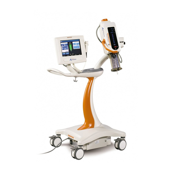
«Imaging System Interface» • «Start Switches» • «Pedestal and Stand Movement» Figure 5 — 1: Mark 7 Arterion Injection System Display Control Unit Injector Head Power Unit 5.1 Injection Protection The following means are provided to protect against over and under injections: An on-screen indication of insufficient volume is provided whenever the total volume programmed to be delivered is greater than the amount of fluid in the syringe.
-
Page 28: Pressure Limiting
® MEDRAD Mark 7 Arterion Injection System 5.2 Pressure Limiting The purpose of the programmed pressure limit is to protect the patient, the catheter, and any disposable device attached to the injector. As a general rule, set pressure limit no higher than the max pressure rating of the weakest component in the fluid path (tubing, stopcocks, connectors, catheters, administration sets, etc.).
-
Page 29: Technical Specifications
5.4 High Pressure Connector Tubing Specifications (Non-Twist & Go) The injection system was designed to use the MEDRAD Mark 7 Arterion Syringe and Twist and Go Syringe. When using the Mark 7 Arterion Syringe, tubing should meet the following specifications to operate in a safe and effective manner.
-
Page 30: Display Control Unit
® MEDRAD Mark 7 Arterion Injection System 5.5 Display Control Unit The injection system Display Control Unit consists of a touch screen display. From the Display Control Unit, an operator can manage protocols, arm and disarm the injector, review injection history, set options, and view help topics.
-
Page 31: Power Unit
5.9 MEDRAD VFlow MEDRAD VFlow (VFlow) enables the use of Variable Flow Rate injections. In the Variable Flow Rate injection mode, the injector automatically re-arms after each injection. A Variable Flow Rate injection can be initiated by the Hand Controller and ranges from 1 — 10 mL/sec in increments of 0.1 mL/sec.
-
Page 32: Medrad Vflow Hand Controller
The Hand Controller button (B) is non-functional and will beep from the Injector head and DCU when depressed. Figure 5 — 5: Hand Controller NOTE: The hand controller is required to perform Variable Flow Rate injections. For installation instructions, see»10.5 — Installing the MEDRAD® VFlow Hand Controller». 5 — 24…
-
Page 33: Pedestal And Stand Movement
System Overview 5.11 Pedestal and Stand Movement 5.11.1 Pedestal System Place pedestal system components into the approximate positions shown in Figure 5 — 6 prior to moving the system. When necessary, lift pedestal by using the handle to move over obstacles. Figure 5 — 6: Approximate Component Positions for System Movement 5 — 25…
-
Page 34: Head Stand (Kma 320 Rt) And Adjustable Height Stand (Kma 330)
® MEDRAD Mark 7 Arterion Injection System 5.11.2 Head Stand (KMA 320 RT) and Adjustable Height Stand (KMA 330) Place hands in the positions shown in Figure 5 — 7 to move an injector Head mounted on a Head Stand and Adjustable Height Stand over obstacles.
-
Page 35: Mark 7 Arterion Stand Mounting Kit Configuration
System Overview 5.11.3 Mark 7 Arterion Stand Mounting Kit Configuration Place the Mark 7 Arterion Stand Mounting Kit components into the approximate positions and place hands in the positions shown in Figure 5 — 8 prior to moving the system.
-
Page 36
® MEDRAD Mark 7 Arterion Injection System 5 — 28… -
Page 37: Using And Understanding The Display Control Unit Screen
Using and Understanding the Display Control Unit Screen The Display Control Unit touch screen has five tabs from which an operator can manage protocols, arm and disarm the injector, review injection history, set options, and view help topics. NOTE: An operator will be locked-out from a Display Control Unit if another operator is performing functions on the Injector Head or another Display Control Unit connected to the same system.
-
Page 38: Actuals Window
® MEDRAD Mark 7 Arterion Injection System 6.1.2 Actuals Window The Actuals window displays Peak (maximum Flow Rate achieved), Delivered (actual total volume delivered), Total Contrast (total volume delivered for the current case), and the End Case button. An operator presses the End Case button after completing a patient procedure and before removing the disposables to retract the syringe plunger.
-
Page 39: Modify Options
Used by Bayer HealthCare Services or Bayer trained personnel to Upgrade activate features. Enables Variable Flow Rate injections when this feature is activated ® MEDRAD VFlow from Upgrade. Contact Bayer to enable this feature. When VFlow is enabled, the system provides a sound when the Hand Audio Feedback Controller plunger is depressed.
-
Page 40: Display Control Unit Lock-Outs
® MEDRAD Mark 7 Arterion Injection System 6.6 Display Control Unit Lock-outs The Display Control Unit will be locked-out while an operator is interacting with the Injector Head controls, or while an operator is accessing another Display Control Unit in a dual Display Control Unit system.
-
Page 41: Using And Understanding The Injector Head
Using and Understanding the Injector Head This chapter describes: • «Injector Head Components» • «Injector Head Position» • «Syringe Interface» • «Pressure Jacket» • «Injector Head Displays» • «Injector Head Controls» • «Armed Light» • «Manual Knob» • «Syringe Heat Maintainer» •…
-
Page 42: Injector Head Position
Mark 7 Arterion Injection System 7.2 Injector Head Position The Mark 7 Arterion Injector Head contains a sensor that monitors the head’s position: Purge (upright) (X), Intermediate (Y), or Inject (downward) (Z). The head position determines how the data displays and the available functions.
-
Page 43: Piston Auto Retract
«6.4 — Options Tab» more information. 7.4 Pressure Jacket The Mark 7 Arterion has a Pressure Jacket designed to hold the syringe in place and help to maintain syringe integrity during use. Figure 7 — 3: Pressure Jacket The Pressure Jacket is manufactured from high impact resistant material; however, sharp impacts such as from dropping, may cause small barely visible cracks to form, which may propagate during subsequent pressure cycles.
-
Page 44: Injector Head Displays
® MEDRAD Mark 7 Arterion Injection System 7.5 Injector Head Displays The Injector Head has two display areas. One area shows the programmed parameters for flow rate, volume, and pressure limit. The other area shows the volume remaining in the syringe.
-
Page 45: Injector Head Controls
Using and Understanding the Injector Head 7.6 Injector Head Controls The Injector Head Controls on the injection head display contain the Enable button, Enable Indicator, Fill Strip, and Auto-Fill button. 7.6.1 Enable Button (F) The Enable button activates the Fill Strip and Auto-Fill button. After pressing the Enable button, the Enable Indicator (G) illuminates and the Fill Strip and Auto-Fill button stay active while in use or for five seconds of inactivity.
-
Page 46: Manual Knob
® MEDRAD Mark 7 Arterion Injection System 7.8 Manual Knob Use the Manual Knob (K) to manually advance or retract the piston. Turn the knob clockwise to advance the piston and counterclockwise to retract the piston. Figure 7 — 6: Manual Knob 7.9 Syringe Heat Maintainer…
-
Page 47: Power Up And Shutdown The Injector
Power Up and Shutdown the Injector This chapter describes: • «Powering up the System» • «Shutdown» 8.1 Powering up the System CAUTION Electric Shock Hazard — Minor or moderate patient and/ or worker injury may result. • Verify that the voltage and frequency marked on the serial tag on the Power Unit matches the voltage and frequency of the electrical outlet.
-
Page 48
® MEDRAD Mark 7 Arterion Injection System 8 — 40… -
Page 49: Setting And Managing Protocols
Setting and Managing Protocols Setting and Managing Protocols Over Volume Hazard — Serious patient injury or death may result. • Do not program a protocol outside of the clinically accepted volume range. • Ensure that the correct volume is programmed in the protocol for the target anatomy. Vessel Dissection Hazard — Serious patient injury or death may result.
-
Page 50: Set Injection Parameters On Home Tab — Phased
® MEDRAD Mark 7 Arterion Injection System NOTE: The displayed values are based on the last used protocol or the default values. 2. Select the box corresponding to a parameter to change it. 3. Use the numeric keypad to enter the protocol parameter.
-
Page 51: Set Injection Parameters On Home Tab — Variable Flow Rate
Controller. As an operator depresses the Hand Controller plunger, the system increases the Flow Rate until it reaches the maximum Flow Rate set by the operator. NOTE: If the Variable Flow Rate option is not visible, go to the Display Control Unit Options tab to enable MEDRAD VFlow. See «6.4 — Options Tab».
-
Page 52: Manage Protocols From The Protocols Tab
® MEDRAD Mark 7 Arterion Injection System 9.2 Manage Protocols from the Protocols Tab NOTE: To store, view, or edit mL/m, Phased, or Variable Flow Rate protocols, enable that protocol type from the Display Control Unit Options tab. See «6.4 — Options Tab».
-
Page 53
Setting and Managing Protocols 9.2.1.2 Create a New Phased mL/s Protocol on the Protocols tab Phased protocols consist of multiple phases of Volumes and flow rates with a single pressure limit and rise time. NOTE: ISI does not function with Phased protocols. 1. -
Page 54
® MEDRAD Mark 7 Arterion Injection System Figure 9 — 6: Index Number c. To enter a new phase, select an empty index number (C). A new phase is added with default values for flow rate and volume. d. Enter the phase values, as needed NOTE: The currently selected values update in the top row parameters. -
Page 55: Recall A Stored Protocol
Setting and Managing Protocols Figure 9 — 7: Protocols Tab — Variable Flow Rate Protocols 3. Select the blank blue button (A). NOTE: If a blank button is not visible, scroll through the list of protocols until one displays. If a blank button is not available or 0 Available displays in the upper right corner, the system cannot store any more protocols.
-
Page 56: Edit An Existing Protocol
® MEDRAD Mark 7 Arterion Injection System 2. Select the Type button to display the type of protocol to be recalled. 3. Select the Sort button to sort the protocols. The options are: • Sort A-Z • Sort Z-A •…
-
Page 57: Delete A Protocol
Setting and Managing Protocols Figure 9 — 9: Edit Phased Protocols e. To commit the values, select a different parameter. Repeat steps b through e for each parameter to be edited. 7. To add phases: a. Select an empty index number (B) for the phase. A new phase is added with Flow Rate and Volume both equal to “1”and Flow Rate is selected.
-
Page 58
® MEDRAD Mark 7 Arterion Injection System 9 — 50… -
Page 59: Preparing For Injection
This chapter describes: • «Installing the Mark 7 Arterion or Twist & Go Syringe» • «Filling and Purging the Mark 7 Arterion or Twist & Go Syringe» • «Installing and Purging Standard High Pressure Connector Tubing» • «Installing and Purging Twist & Go HPCT»…
-
Page 60
® MEDRAD Mark 7 Arterion Injection System CAUTION Environmental Contamination Hazard — Minor or moderate patient and/ or worker injury may result. • Visually inspect contents and package before use. • Do not use disposables past Use By date identified on the package. -
Page 61: Filling And Purging The Mark 7 Arterion Or Twist & Go Syringe
Alternatively, on the Injector Head, press the Enable button and then press and release the Auto-Fill button (I). The Mark 7 Arterion fills the syringe with the preconfigured contrast volume at the preconfigured speed. The volume and speed are configured from the Display Control Unit Options tab.
-
Page 62: Installing And Purging Standard High Pressure Connector Tubing
® MEDRAD Mark 7 Arterion Injection System 8. Carefully observe the FluiDots indicators to ensure that fluid is present in the syringe. Verify that the FluiDots indicators are round in the filled portion of the syringe. The rounded shape of the FluiDots indicators varies according to the type of contrast media, but an oblong shape indicates the presence of air.
-
Page 63: Installing And Purging Twist & Go Hpct
Preparing for Injection NOTE: Refer to «5.4 — High Pressure Connector Tubing Specifications (Non-Twist & Go)» for high pressure connector tubing specifications. 1. Remove the Dust cap from the syringe tip if attached. 2. Insert the high pressure connector tubing into FasTurn nut (H) on the Mark 7 Arterion Syringe.
-
Page 64: Installing The Medrad Vflow Hand Controller
® MEDRAD Mark 7 Arterion Injection System Figure 10 — 3: Twist & Go Connection 3. Turn the (A) Luer nut clockwise to securely tighten the high pressure connector tubing to the syringe tip (B). 4. Purge all air from the high pressure connector tubing. Turn the Manual Knob clockwise to push contrast out until all of the air bubbles have been removed from the High Pressure Connector Tube.
-
Page 65: Connecting To And Purging The Catheter
Preparing for Injection 10.6 Connecting to and Purging the Catheter Air Embolism Hazard — Serious patient injury or death may result. • Advance the piston prior to connection between the high pressure connector tubing and a catheter or other non-Bayer disposables including administration sets and additions to administration sets, such as but not limited to bleed back control devices and pressure transducers.
-
Page 66: Enabling 15 Ml Purge Feature And Choosing Configuration Options
® MEDRAD Mark 7 Arterion Injection System 6. Stop aspirating with manual knob once blood is visualized in the high pressure connector tubing. 7. Verify that there no air is in the high pressure connector tubing. a. If there is air in the tubing, disconnect from patient, remove air, and try fluid to fluid connection again.
-
Page 67: Defining A Protocol
Preparing for Injection Table 10 — 1: 15 mL Purge Configuration Options (ON or OFF) 15 mL Purge ON 15 mL Purge OFF < ≥15 mL Plunger <15 mL Plunger ≥15 mL Plunger 15 mL Plunger Retraction Retraction Retraction Retraction MUST purge 3.5 MUST purge 3.5 mL or more ONLY…
-
Page 68
® MEDRAD Mark 7 Arterion Injection System Figure 10 — 5: ISI Enabled 10 — 60… -
Page 69: Arming And Injecting
Arming and Injecting Vessel Dissection Hazard — Serious patient injury or death may result. • Do not move injector head or pedestal while catheter is connected to patient. This chapter discusses: • «Purged Air Confirmation» • «Arming the Injector» • «Performing an Injection»…
-
Page 70: Arm Single Mode
® MEDRAD Mark 7 Arterion Injection System Before an operator performs the arming process, the Sentinel window displays messages to indicate any remaining tasks that need to be performed to complete the arming process: • a syringe is present. •…
-
Page 71
Arming and Injecting Single mL/m and Phased protocols: select Arm (B). Figure 11 — 2: Phased protocol 3. Visually confirm that all air has been purged from the syringe and disposable set, and select Yes. NOTE: There is sufficient volume remaining in the syringe. For Single mL/s and mL/m protocols with insufficient volume remaining in the syringe for the programmed protocol, the system gives the option of overriding the programmed volume and using the available volume remaining. -
Page 72: Arm Multi Mode
® MEDRAD Mark 7 Arterion Injection System 11.2.2 Arm Multi Mode NOTE: The term start switch in this section is used to refer to the hand switch, foot switch or hand controller. The Arm Multi mode is available only for Single mL/s and Variable Flow Rate protocols. This mode allows for multiple injections per arming sequence.
-
Page 73: Performing An Injection
Injection». 11.3 Performing an Injection The Mark 7 Arterion Injection System can perform Fixed Flow Rate and Variable Flow Rate injections. For Fixed Flow Rate, Arm Single mode injections, the injector disarms after the injection is complete or an operator releases the hand switch, foot switch, or Imaging System start switch. For Fixed Flow Rate, Arm Multi mode injections and Variable Flow Rate injections, the injector remains armed until one of the disarm criteria are met.
-
Page 74: Performing A Phased Injection
Imaging System to confirm its internal configuration. The tables in the subsections below show the Imaging Systems covered in this section and how each functions with the Mark 7 Arterion Injection System. NOTE: Call Bayer HealthCare Services to determine compatibility of other Imaging Systems.
-
Page 75
Arming and Injecting 11.3.5.1 Injection System Initiates Injection Table 11 — 1 shows the results of pressing the Mark 7 Arterion Injection System hand switch or foot switch to initiate the protocol. Table 11 — 1: Injection System Initiates Injection… -
Page 76
11.3.5.3 Injection System and Imaging System Initiate Protocol — (Philips Imaging Systems Only) Table 11 — 3 shows the results of pressing the Mark 7 Arterion Injection System hand switch or foot switch and the Philips Imaging System start switch simultaneously to initiate the protocol. -
Page 77: Completing An Injection
Arming and Injecting Table 11 — 3: Injection System and Imaging System Initiate Protocol Bayer Catalog Number Action XMC 928A Independent Actions — See 1 knob operation Tables 10-1 and 10-2 XMC 928A Injection and X-ray 2 knob operation XMC 945 40 No Action XMC947R Independent Actions — See…
-
Page 78: Refilling Syringe During A Procedure
Alternatively, on the Injector Head, press the Enable button and then press the Auto-Fill button. The Mark 7 Arterion fills the syringe with the preconfigured contrast volume at the preconfigured speed. The volume and speed are configured from the Display Control Unit Options tab.
-
Page 79: Refilling Syringe With 15 Ml Purge Feature Enabled
Arming and Injecting 8. Visually confirm that all air bubbles have been removed from the syringe. Tap the pressure jacket after filling to facilitate air removal. 9. Secure the distal connector of the high pressure connector tubing. 10. Turn the Manual Knob clockwise to push contrast out until all of the air bubbles have been removed from the high pressure connector tubing.
-
Page 80
® MEDRAD Mark 7 Arterion Injection System 11 — 72… -
Page 81: Tear Down
Tear Down Biological Contamination Hazard — Serious patient and/or worker injury or death may result. • Properly discard disposables after use or if contamination may have occurred during setup or use. This chapter discusses how to tear down and immediate cleaning of the injection system. 12.1 Remove Disposables Bloodborne Contamination Hazard — Serious patient and/or worker injury or death may result.
-
Page 82: Storing The Injector
® MEDRAD Mark 7 Arterion Injection System 6. Wipe components with: • a germicidal wipe, or • a bleach wipe, for isolation patients NOTE: If contrast media has leaked inside any system component, turn off the power immediately. The affected subassembly should be disassembled and cleaned by Services personnel or returned to Bayer HealthCare Services.
-
Page 83: System Messages
System Messages The Mark 7 Arterion Injection System displays Sentinel Messages and Popups to alert the operator that action is required. This chapter describes: • «Error Messages» • «Sentinel Messages» • «Popup Messages» 13.1 Error Messages Electric Shock Hazard — Serious patient and/ or worker injury or death may result.
-
Page 84
® MEDRAD Mark 7 Arterion Injection System Table 13 — 1: Sentinel Messages Sentinel Message Description/Resolution Use the handle and the back of the Injector Head (but not the Manual Knob or tubing) to rotate the Head in the Purge position (upward), Rotate head up and purge and purge the system of all air. -
Page 85: Popup Messages
System Messages 13.3 Popup Messages Popups display on the touch screen and require the operator to make a selection on the screen to close the Popup. Table 13 — 2: Popup Messages Popup Message Description/Resolution The Check for Air popup displays when initially arming the injector.
-
Page 86
® MEDRAD Mark 7 Arterion Injection System Table 13 — 2: Popup Messages Popup Message Description/Resolution The system was not able to achieve the programmed flow rate. System Disarmed — Pressure limit exceed. The high pressure connector tubing or catheter Check for occlusion, reduce rate or increase may be kinked limiting the flow of contrast. -
Page 87
System Messages Table 13 — 2: Popup Messages Popup Message Description/Resolution The system remained idle for 30 minutes. System Disarmed — User Inactivity Timeout. Rearm the system. ISI is not communicating correctly with the System Disarmed — ISI not ready system. -
Page 88
® MEDRAD Mark 7 Arterion Injection System Table 13 — 2: Popup Messages Popup Message Description/Resolution Displays when an operator enters an invalid Please enter a valid month. month. Enter a valid month. Change flow mode? Select Yes to change the flow mode to mL/m. -
Page 89: Virtualcare Option
VirtualCare Option VirtualCare is a Service expansion option that can be installed for the Mark 7 Arterion Injection System. The VirtualCare provides remote service functionality that allows Bayer HealthCare Services to remotely update injector firmware, diagnose injector errors, and retrieve logs.
-
Page 90
® MEDRAD Mark 7 Arterion Injection System 14 — 82… -
Page 91: Cleaning And Maintenance
Cleaning and Maintenance Cross Contamination Hazard — Serious patient and/or worker injury or death may result. • Do not contact disposables with cleaning agent during cleaning. • Do not conduct cleaning process during injection procedure. NOTICE Electro-Mechanical Hazard — Equipment Damage may result. •…
-
Page 92
® MEDRAD Mark 7 Arterion Injection System 3. Clean the Syringe Heat Maintainer with a dampened cloth using soap and water. 4. Remove the Drop Front Cover. 5. Clean the Drop Front Cover with a soft cloth or a paper towel dampened with a cleaning solution to remove contrast media and other contamination. -
Page 93: Inspecting The Injector Head
Cleaning and Maintenance 8. Fully advance the piston 9. Turn off the system at the Power Unit. 10. Clean the piston. 11. Clean the inner area of the syringe interface. 12. Clean the drop front. The drop front cone should pivot freely back and forth. If it does not, it may be contaminated with contrast.
-
Page 94: Inspecting The Heat Maintainer
® MEDRAD Mark 7 Arterion Injection System Stress Cracks may appear after the Pressure Jacket has been subjected to a number of pressure cycles. These tiny cracks appear around the front area of the Pressure Jacket, and usually form a pattern around the jacket’s circumference.
-
Page 95: Inspecting The Pedestal
Cleaning and Maintenance 15.1.7 Inspecting the Pedestal • Inspect the base, column, casters and handle for cracks and other defects that could weaken the structure • Ensure all mounting bolts and screws are secure. • Ensure that the casters roll smoothly with no binding or scraping. •…
-
Page 96: Performing An Operational Checkout
® MEDRAD Mark 7 Arterion Injection System 4. Vacuum or rinse the air filter with water and thoroughly dry before re-installing. 5. Re-install the clean, dry air filter (Note the direction of arrow for air flow — air should flow into the unit).
-
Page 97
Cleaning and Maintenance b. Vary the position of your finger on the Fill Strip to ensure the piston load speed varies. c. Ensure that the Volume Remaining display on the head decreases. 10. Press the Enable button, and press Reverse on the Fill Strip within five seconds. a. -
Page 98: Annually
® MEDRAD Mark 7 Arterion Injection System 18. Select either Arm Single or Arm Multiple to arm the injector. a. Press any button on the Injector Head. b. Ensure the system disarms. 19. Select either Arm Single or Arm Multiple to arm the injector.
-
Page 99: Installation — System And Accessory
Installation — System and Accessory CAUTION Mechanical Hazard — Minor or moderate patient and/ or worker injury may result. • Do not create a trip hazard when routing cables. • Follow installation procedures including use of proper screws and plugging all unused holes.
-
Page 100: Pedestal Mount Installation
• Do not mount DCU to Articulating Arm. The Mark 7 Arterion pedestal mount configuration ships in two boxes as noted in “Unpacking the Injection System.” The installer needs to complete the pedestal assembly, attach the Injector Head and Display Control Unit, route cables, and make the connections to the Power Unit.
-
Page 101
Installation — System and Accessory Figure 16 — 3: Attach Injector Head to Articulating Arm c. Secure the Injector Head by turning the Injector Head Knob as far as possible clockwise. d. Ensure that the Injector Head Knob is as tight as possible to facilitate a secure fit of the Injector Head in the Articulating Arm. -
Page 102
® MEDRAD Mark 7 Arterion Injection System Figure 16 — 5: Insert Power Unit • Secure the Power Unit with the four thumb screws (J) attached to the base. 15. Connect Display Control Unit cord to Display Control Unit connection on the top of the Power Unit. -
Page 103: Power Unit Installation
Electric Shock Hazard — Serious patient and/ or worker injury or death may result. • Use only power cord approved for use on Mark 7 Arterion. • For U.S installations, equipment shall only be connected to Hospital Grade or Hospital Only outlets.
-
Page 104: Power Unit Connections
® MEDRAD Mark 7 Arterion Injection System 16.3.1 Power Unit Connections The Power Unit has connection ports on the top plate, front plate, and back plate. When the Power Unit ships from the factory, only the ports on the top plate and front plate have live connections. This section shows the location of each port and provides a brief description of each.
-
Page 105: Power Unit Floor Mount Bracket Assembly
Installation — System and Accessory Display Control Unit Connection for a second Display Control Unit Future Expansion Port in a two Display Control Unit system Power Switch The connections on the back plate do not have live connections when the Power Unit ships from the factory.
-
Page 106: Relocate Power Unit Connectors
Disconnect the power cord before removing or replacing PC boards. The Display Control Unit and Injector Head connectors on the Mark 7 Arterion Power Unit can be moved to accommodate different configurations. The Display Control Unit and Injector Head connectors found on the top of the Power Unit can be moved to the back.
-
Page 107: Injector Head Mounting Options
16.4.3 Adjustable Table Bracket Installation (KMA 350) Refer to 3040373 for installation instructions. 16.4.4 Overhead Counterpoised System Installation ® For OCS installation instructions refer to the MAVIG Portegra2 Suspension System for MEDRAD Injectors Installation Manual (MED01002E). 16.5 Display Control Unit Mounting Options •…
-
Page 108: Desk Stand Kit Installation
® MEDRAD Mark 7 Arterion Injection System 16.5.2 Desk Stand Kit Installation P/N 3007412 #8-32 x 5/8” Figure 16 — 15: Attach Bracket (A) to Display Control Unit Stand P/N 600-5007-400 Figure 16 — 16: Attach Rubber Feet Figure 16 — 17: Display Control Unit Back — Remove Screws Figure 16 — 18: Display Control Unit Desk Stand Attached NOTE: Reuse #8-32 1/2”…
-
Page 109: Fixed Table Mount Installation
Installation — System and Accessory 16.5.3 Fixed Table Mount Installation NOTICE Electro-Mechanical Hazard — Equipment damage may result. • Before installing the Table Mount, ensure the table rail can withstand a minimum vertical static load of 18 kg (40 lbs.) Refer to the table manufacturer documentation for weight load information.
-
Page 110
® MEDRAD Mark 7 Arterion Injection System Figure 16 — 20: Tightening the Clamp Knob 4. Using the 3/16” Hex Key provided, turn the adjusting screw (A) clockwise until Mounting Lever (B) contacts the bottom of the rail. Figure 16 — 21: Adjust Screw and Mounting Lever 5. -
Page 111: Wall Mount Bracket Installation
Installation — System and Accessory 16.5.4 Wall Mount Bracket Installation NOTE: Before attaching the bracket to the wall, the installer must know if the wall studs in the room are made of metal or wood. This will determine the kind of hardware required to complete the installation.
-
Page 112
® MEDRAD Mark 7 Arterion Injection System 8. Connect the cable to the rear of the Display Control Unit (a small flat head screwdriver may be required). Route the Display Control Unit cable toward the Display Control Unit wall bracket hinge. -
Page 113: Accessory Installation
Installation — System and Accessory Figure 16 — 27: Wall Mount Friction Plate — Close-up 2. Remove the wing nut (B) from the top of the pivot bolt (A). 3. Remove the washer and spring (C). 4. Lift the mounting plate (D) off of the mounting pins and flip over. 5.
-
Page 114: Syringe Pressure Jacket Installation
® MEDRAD Mark 7 Arterion Injection System Figure 16 — 29: Syringe Heat Maintainer Figure 16 — 30: Syringe Heat Maintainer Connected 16.6.2 Syringe Pressure Jacket Installation Install the Pressure Jacket on to the front of the injector prior to installing a syringe.
-
Page 115: Hand Switch Mount Kit
Installation — System and Accessory Figure 16 — 32: Hand Switch Display Control Unit Location Figure 16 — 33: Use Clip to Attach Hand Switch Cable to the Display Control Unit 16.6.4 Hand Switch Mount Kit The hand switch mount kit contains hardware to allow the operator to mount the hand switch to any flat surface (such as the back of the Display Control Unit) and onto a pole or similarly shaped object.
-
Page 116: Display Control Unit Sterile Sheath Installation
NOTE: Contents are sterile. Display Control Unit sheath should be applied using sterile technique. The Mark 7 Arterion Display Control Unit Sterile Sheath is intended for single patient use. 1. Use sterile technique to open the Display Control Unit Sterile Sheath package.
-
Page 117: Cable Bracket Installation
NOTE: DO NOT photocopy the template as photocopying may distort the image. ALWAYS MEASURE BEFORE DRILLING. 2. Route MEDRAD Mark 7 Arterion Injection System Injector Head Extension Cable and Display Control Unit Cable through the table opening. 3. Locate the Table Cable Bracket (A). Remove the four screws (B) attaching the insert to the bracket.
-
Page 118
® MEDRAD Mark 7 Arterion Injection System cient length of the Display Control Unit Cable extending beyond the opening of the bracket to connect to the Display Control Unit in the desired location. NOTE: When installing only one cable, insert the appropriate sized plug (included) into the empty hole. -
Page 119
NOTE: DO NOT photocopy the template as photocopying may distort the image. ALWAYS MEASURE BEFORE DRILLING. 2. Route Mark 7 Arterion Injection System Injector Head Extension Cable and Display Control Unit Cable through the table opening. 3. Locate the Table Cable Bracket (A). Remove the four screws (B) attaching the insert to the bracket. -
Page 120
NOTE: DO NOT photocopy the template as photocopying may distort the image. ALWAYS MEASURE BEFORE DRILLING. 2. Thread MEDRAD Mark 7 Arterion Injection System Injector Head Extension Cable and Display Control Unit Cable through the floor opening. 16 — 112… -
Page 121
Installation — System and Accessory Figure 16 — 43: Cable Routing for Extension Cables NOTE: Avoid routing extension cables with high power cables. 3. Locate the Floor Cable Bracket (A). Remove the four screws (B) attaching the insert to the bracket. -
Page 122
NOTE: DO NOT photocopy the template as photocopying may distort the image. ALWAYS MEASURE BEFORE DRILLING 2. Thread MEDRAD Mark 7 Arterion Injection System Injector Head Extension Cable and Display Control Unit Cable through the floor opening. NOTE: Avoid routing extension cables with high power cables. -
Page 123
Installation — System and Accessory Figure 16 — 47: Cable Strain Relief Removal 6. Insert the cables connectors in the corresponding sized holes in the plate. Figure 16 — 48: Removing Cable Plate NOTE: If attaching the DCU cable, remove the cover plate (C) from the plate. 7. -
Page 124: Stand Mounting Kit Installation
16.7 Stand Mounting Kit Installation The Mark 7 Arterion Pedestal Mounting Kit is for use with the KMA 320 RT and the KMA 330. NOTE: Ensure the KMA 320 RT and KMA 330 have five (5) locking casters. If the stand does not have five locking casters, contact service for part number 699-4645-100.
-
Page 125
Installation — System and Accessory 5. Lock the casters on the pedestal. 6. Position Power Unit on the stand as shown below. 7. Loosely attach the Crescent Clamp (D) to the bottom half of the Tube Clamp using two 10-32 x 3/4 socket head screws (E) and 3/16 hex key. -
Page 126: Display Control Unit (Dcu) Support Assembly Installation
® MEDRAD Mark 7 Arterion Injection System 16.9 Display Control Unit (DCU) Support Assembly Installation 1. Insert the DCU Mounting Bushing (A) into the DCU Support Post (B). 2. Align holes and secure with two 8-32 x 3/8 Phillips screws (C) using a #2 Phillips screw driver.
-
Page 127
Installation — System and Accessory 3. Ensure the Pedestal Arm has been rotated counterclockwise until you hit the stop. 4. Locate two DCU Mounting Bracket halves (D). 5. Orient halves together ensuring each threaded hole lines up with a through hole. 6. -
Page 128
® MEDRAD Mark 7 Arterion Injection System 9. Insert and fasten one 1/4-20 x 1-1/4 screw (E) on the DCU Mounting Bracket into the hole closest to the DCU Support Post. 10. Rotate DCU Support Bracket so that the bracket is positioned directly under the Pedestal Arm. -
Page 129: Specifications
Specifications This chapter lists: • «System Component Weights and Dimensions» • «Mounting Components Weights and Dimensions» • «ISI Technical Specifications» • «Environmental Specifications» 17.1 System Component Weights and Dimensions NOTE: All listed weights and dimensions are approximate. 17.1.1 Pedestal System Weight and Dimensions 47.3 in 120.1 cm 90°…
-
Page 130: Display Control Unit Weight And Dimensions
® MEDRAD Mark 7 Arterion Injection System 17.1.2 Display Control Unit Weight and Dimensions 3.040 in. 7.7 cm 12.62 in. 32.1 cm 11.042 in. 28 cm Weight: 7lbs. (3.18kg) 17.1.3 Injector Head Weight and Dimensions 5.470 in. 13.9 cm 21.219 in.
-
Page 131: Power Unit Weight And Dimensions
Specifications 17.1.4 Power Unit Weight and Dimensions 9.765 in. 24.8 cm 15.213 in. 4.641 in. 38.6 cm 11.8 cm 9.765 in. 24.8 cm Weight: 11 lbs. (4.99 kg) 17.2 Mounting Components Weights and Dimensions NOTE: All listed weights and dimensions are approximate. 17.2.1 Pedestal Mount Weight and Dimensions Weight*: 100 lbs.
-
Page 132: Head Stand Weight And Dimensions
® MEDRAD Mark 7 Arterion Injection System 17.2.2 Head Stand Weight and Dimensions 2 in. 5.08 cm 48.5 in. 123.19 cm 35.6 in. 26.75 in. 90.42 cm 67.95 cm Weight*: 51.4 lbs. (23.32 kg) *Weight does not include the Injector Head weight.
-
Page 133: Stand Mounting Kit Components Weights And Dimension
Specifications 17.2.4 Stand Mounting Kit Components Weights and Dimension. 17.2.4.1 Display Control Unit (DCU) Bracket Weight and Dimensions Weight: 4.0 lbs. (1.8 kg) *Measurements are in inches. Weight does not include DCU weight. 17.2.4.2 Power Unit Bracket Weight and Dimensions Weight: 1.2 lbs.
-
Page 134: Adjustable Table Mount (Kma 350) Weight And Dimensions
® MEDRAD Mark 7 Arterion Injection System 17.2.5 Adjustable Table Mount (KMA 350) Weight and Dimensions 1.99 in. 5.1 cm 12 in. Compressed 30.5 cm 17 in. Extended 43.2 cm 5.375 in. 13.7 cm 1.44 in. 3.7 cm Weight*: 5.4 lbs. (2.44 kg) *Weight does not include the Injector Head weight.
-
Page 135
Specifications 17.2.6.1 Ceiling Mount Weight and Dimensions Long 39.4 in. (100.1 cm) Medium 33.5 in. (85.1 cm) Short 22.8 in. (57.9 cm) 29.5 in. 360 o 74.9 cm 360 o 35.8 in. 90.9 cm 360 o 50 o 360 o 360 o 32 in. -
Page 136
® MEDRAD Mark 7 Arterion Injection System 17.2.6.3 Wall Mount Weight and Dimensions 70.5 in. 179 cm Required for fully extended rotation 45 ° 31.5 in. 3.5 in. 31.5 in. 80 cm 80 cm 9 cm 22 in. 56 cm 1.5 in. -
Page 137: Fixed Table Mount Weight And Dimensions
Specifications 17.2.7 Fixed Table Mount Weight and Dimensions 1.99 in. 5.1 cm 8.06 in. 20.5 cm 5.375 in. 13.7 cm 1.438 in. 3.7 cm Weight*: 3.8 lbs (1.72 kg) *Weight does not include the Display Control Unit weight. 17.2.8 Display Control Unit Desk Stand Mount Weight and Dimensions 8.76 in.
-
Page 138: Display Control Unit Wall Mount Weight And Dimensions
® MEDRAD Mark 7 Arterion Injection System 17.2.9 Display Control Unit Wall Mount Weight and Dimensions 12.56 in. 31.9 cm 11.87 in. 13.08 in. 30.1 cm 33.2 cm 1 in. 2.5 cm 1.83 in. 4.6 cm Weight*: Weight*: 4.4 lbs (1.99 kg) *Weight does not include the Display Control Unit weight.
-
Page 139: Isi Technical Specifications
NOTE: Systems are configured for Universal ISI operation. If configuring for Siemens sys- tem, contact local service for assistance. 17.3.1 ISI Output Specifications The tables below list the output signals and the relay contact outputs for the Mark 7 Arterion ISI. Table 17 — 1: Output Signals Signal Name Description This signal is a pair of relay contacts output from the Injector.
-
Page 140: Isi Input Specifications
Mark 7 Arterion Injection System 17.3.2 ISI Input Specifications The Mark 7 Arterion ISI is activated by a contact closure at the imaging system, and it is powered by internal 24VDC isolated supply with short circuit protection at the Mark 7 Arterion Injector.
-
Page 141
Arterion design and is only presented for informational purposes. Output signal to Imaging System that shorts pins 14 and 15 together as an Handswitch closed indication that the Mark 7 Arterion hand switch or foot switch is pressed. 17 — 133… -
Page 142
® MEDRAD Mark 7 Arterion Injection System ISOLATED +24Vdc INJ_START ISOLATED RELAY GROUND ISOLATED +24Vdc INJ_DISARM ISOLATED RELAY GROUND ISOLATED +24Vdc INJ_HAND_ SWITCH_DISABLE RELAY EXTENDED_ARM RELAY INJECTING RELAY X-RAY_TRIGGER RELAY A closed relay contact INJ_HAND_SWITCH_ON indicates the corresponding signal is active… -
Page 143
Specifications INJ_START RELAY ISOLATED GROUND ISOLATED +24Vdc INJ_DISARM ISOLATED RELAY GROUND ISOLATED +24Vdc INJ_HAND_ SWITCH_DISABLE RELAY ISOLATED +24Vdc EXTENDED_ARM RELAY ISOLATED GROUND ISOLATED +24Vdc INJECTING ARMED_RETURN ISOLATED GROUND X-RAY_TRIGGER RELAY A closed relay contact indicates the corresponding INJ_HAND_SWITCH_ON signal is active RELAY Imaging System Injector Side… -
Page 144: Environmental Specifications
® MEDRAD Mark 7 Arterion Injection System 17.4 Environmental Specifications 17.4.1 Operating The system may not meet all performance specifications if operated outside the following conditions. Temperature: +15ºC to +30º C (+59ºF to +104ºF) Humidity: 20% to 75% R.H. Air Pressure: 70 kPa to 106 kPa after it has stabilized to within the operating pressure ranges.
-
Page 145: Continuous Mode Of Operation
Operation under normal load for an unlimited period, without the specified limits of temperature being exceeded. 17.4.9 EU Directive The MEDRAD Mark 7 Arterion Injection System complies with the essential requirements of the Medical Device Directive 93/42/EEC and bears the CE Mark to show conformity with the provisions of this Directive.
-
Page 146
® MEDRAD Mark 7 Arterion Injection System 17 — 138… -
Page 147: Options And Accessories
Options and Accessories The sections below list catalog numbers for: • «Mark 7 Arterion System Mount Options» • «Mark 7 Arterion Accessory Devices and Kits» • «Mark 7 Arterion Cords and Cables» • «OCS Mounting Systems» • «OEM Imaging System Interface Cables»…
-
Page 148: Display Control Unit Mount Options
Description Catalog Number Floor Cable Bracket ART 700 CB F Table Cable Bracket ART 700 CB T 18.3 Mark 7 Arterion Accessory Devices and Kits 18.3.1 Switches Description Catalog Number Foot switch 25 ft. (7 m) (Optional) ART 700 FS Hand switch 6 ft.
-
Page 149: Mark 7 Arterion Cords And Cables
Options and Accessories 18.4 Mark 7 Arterion Cords and Cables 18.4.1 Power Cords Description Catalog Number Power Cord — North America and Japan — Standard Length AVA 500 PC110V Power Cord — North America and Japan — 20 ft. (6 m)
-
Page 150: Ocs Mounting Systems
® MEDRAD Mark 7 Arterion Injection System 18.5 OCS Mounting Systems 18.5.1 Stationary Ceiling Mount Description Catalog Number Portegra — Stationary Ceiling Mount — 22.8 in. (58 cm) Post OCS CEIL 58-P Portegra — Stationary Ceiling Mount — 33.5 in. (85 cm) Post OCS CEIL 85-P Portegra — Stationary Ceiling Mount — 39.4 in.
-
Page 151: Philips
Options and Accessories 18.6.2 Philips Description Catalog Number MultiDiagnost (MD) and Integris, 15 ft. (4.5 m)-ISI, Equipotential XMC 925A Integris (Including Integris Allura), 15 ft. (4.5 m) ISI, Equipotential XMC 925A XPER, 15 ft. (4.5 m)-ISI, Power, Equipotential XMC 927A XPER, 26 ft.
-
Page 152
® MEDRAD Mark 7 Arterion Injection System 18 — 144… -
Page 153
Appendix — A Cable Bracket Installation Templates TABLE MOUNT CABLE BRACKET HOLE TEMPLATE NOTE TEMPLATE MAY NOT BE TO SCALE. ALWAYS MEASURE BEFORE DRILLING. 3.70” (93.98 mm) 0.17” (4.19 mm) Through-Hole 1.0” DO NOT Photocopy. Photocopying Can Distort The Template. 3 cm 5.90”… -
Page 154
® MEDRAD Mark 7 Arterion Injection System TABLE MOUNT CABLE INSERT HOLE TEMPLATE NOTE TEMPLATE MAY NOT BE TO SCALE. ALWAYS MEASURE BEFORE DRILLING. 2.20” (55.88 mm) 2.20” (55.88 mm) 1.10” (27.94 mm) MINIMUM MINIMUM 2.60”(66.04 mm) 0.14” (3.45 mm) -
Page 155
5.00” (127.00 mm) 0.28” (7.13 mm) 0.50” (12.70 mm) X Through-Hole 1.25” (31.80 mm) FOR CABLE CONDUIT FOR CEMENT FLOOR INSTALLATION INSTALLATION FLOOR MOUNT CABLE BRACKET HOLE TEMPLATE NOTE TEMPLATE MAY NOT BE TO SCALE. ALWAYS MEASURE BEFORE DRILLING. DO NOT Photocopy. 1.0”… -
Page 156
® MEDRAD Mark 7 Arterion Injection System A — 148… -
Page 157
Home tab 29 Actuals window 29, 30 inspection 86 adjustable table mount installation 99 weight and dimensions 124 mounting options 99, 140 Arm Multi 64 Options tab 30 prerequisites 64 sterile sheath 22 Arm Single 62 sterile sheath installation 108 armed light 33, 37 wall mount 103 arming… -
Page 158
® MEDRAD Mark 7 Arterion Injection System mount 107 Inject position 34 head stand Intermediate position 34 weight and dimensions 124 Purge position 34 Help tab 31 syringe interface 34 high pressure connector tubing injector storage 74 installation 54, 55… -
Page 159
Protocols tab 30 Pedestal create Phased protocol 45 cleaning 87 create Single ml/m 44 inspection 87 create Single ml/s 44 installation 92 purge weight and dimensions 123 confirmation 61 pedestal system high pressure connector tubing 55 weight and dimensions 121 purge action 61 piston syringe 53, 70… -
Page 160
® MEDRAD Mark 7 Arterion Injection System weight and dimensions 130 weight and dimensions adjustable table mount 124 desk stand 129 Display Control Unit 122 Fixed table mount 129 head stand 124 Injector Head 122 OCS 126 Pedestal 123 pedestal system 121… -
Page 162
Bayer Medical Care Inc. Bayer, the Bayer Cross, MEDRAD, Mark 7 Arterion, MEDRAD Mark 7 Arterion, ProVis, FluiDots, MEDRAD VFlow, Twist & Go and VirtualCare may be registered trademarks of Bayer in the US and other countries.
-
Bookmarks
-
ENGLISH, page 7
-
РУССКИЙ, страница 35
-
FRANÇAIS, page 13
-
ESPAÑOL, página 17
-
DEUTSCH, seite 11
-
ITALIANO, pagina 15
-
DUTCH, pagina 23
-
PORTUGUÊS, página 57
-
SVENSKA, sida 21
-
POLSKI, strona 29
-
DANSK, side 25
-
SUOMI, sivu 27
-
ČEŠTINA, strana 41
-
NORSK, side 33
-
ΕΛΛΗΝΙΚΆ, σελίδα 19
-
MAGYAR, oldal 45
-
SLOVENČINA, strana 47
-
TÜRKÇE, sayfa 39
-
ROMÂNĂ, pagina 43
-
SLOVENŠČINA, stran 65
-
БЪЛГАРСКИ, страница 37
-
日本語, 9ページ
-
LIETUVIŲ, puslapis 55
-
EESTI, lehekülg 61
-
LATVIEŠU, 53. lappuse
-
УКРАЇНСЬКА, сторінка 75
-
조선말/한국어, 49페이지
-
漢語, 第 67 页
-
HRVATSKI, stranica 51
-
BAHASA INDONESIA, halaman 71
-
ไทย, หน้า 59
-
ҚАЗАҚША, 73-бет
-
TIẾNG VIỆT, trang 77
Quick Links
Disposable Syringe / Seringue jetable
Instructions for Use / Mode d’emploi
Catalog Number
Product Name
Référence catalogue
Nom du Produit
Disposable Syringe 150 mL with Quick Fill Tube
ART 700 SYR
Seringue jetable 150 mL avec canule de remplissage rapide
©2011-2014, 2017, 2019 Bayer. This material may not be reproduced, displayed, modified,
or distributed without the express prior written consent of Bayer.
©2011-2014, 2017, 2019 Bayer. Ce matériel ne peut pas être reproduit, exposé, modifié ou
diffusé sans l’accord écrit explicite de Bayer.
Bayer, the Bayer Cross, MEDRAD, Mark 7 Arterion, MEDRAD Mark 7 Arterion
MEDRAD FluiDots are trademarks owned by and/or registered to Bayer in the U.S. and/or
other countries.
Bayer, la croix de Bayer, MEDRAD, Mark 7 Arterion, MEDRAD Mark 7 Arterion, FluiDots, et
MEDRAD FluiDots sont des marques commerciales qui détenues et/ou déposées par Bayer
aux États-Unis et/ou dans d’autres pays.
A glossary of the symbols used on the MEDRAD® Mark 7 Arterion sterile disposable
products can be found on page 2 of these Instructions for Use.
Bayer Medical Care Inc.
1 Bayer Drive
Indianola, PA 15051-0780
U.S.A.
Phone: +1 (412) 767-2400
+1 (800) 633-7231
Fax:
+1 (412) 767-4120
Bayer Medical Care B.V.
Horsterweg 24
6199 AC Maastricht Airport
The Netherlands
Phone: +31 (0) 43-3585601
Fax:
+31 (0) 43-3656598
Importer BMC B.V.:
Bayer Medical Care B.V.
Avenue Céramique 27
6221 KV Maastricht,
FluiDots, and
,
The Netherlands
READ BEFORE USING
À lire avant l’utilisation
日本語
English
7
Deutsch
11
Français
Italiano
15
Español (España)
ελληνικά
19
Svenska
Nederlands
23
Dansk
Suomi
27
Polski
Português
31
Norsk
(Brasileiro)
Русский
35
Български
Türkçe
39
Česky
Română
43
Magyar
한국어
Slovenský
47
Hrvatski
51
Latvija
Português
Lietuvių
55
(Europeu)
ไทย
59
Eesti
Srpski
63
Slovenščina
67
Español (LatAm)
繁體中文
Bahasa
Қазақша
71
Indonesia
Tiếng Việt
Українська
75
86617587 Rev. A
March 14, 2019
9
13
17
21
25
29
33
37
41
45
49
53
57
61
65
69
73
77
Summary of Contents for Medrad Mark 7 Arterion
Table of Contents for Medrad Mark 7 Arterion:
-
59 : �
-
19 Ανατρέξτε στην επόμενη σελίδα για Πλήρωση, Εκκένωση και Αφαίρεση της Σύριγγας Εισαγωγή: ∆ιαβάστε τις πληροφορίες που περιέχονται στις παρούσες οδηγίες χρήσης. Η κατανόηση των πληροφοριών θα σας βοηθήσει στην ορθή χρήση της σύριγγας MEDRAD ® Mark 7 Arterion. Σημαντική σημείωση ασφαλείας: Η σύριγγα MEDRAD Mark 7
-
24 1. Controleer of de zuiger van de spuit volledig is teruggetrokken. Om de zuiger terug te trekken, drukt u op de knop Inschakelen (A), en drukt u vervolgens op de vulstrip (C) op de pijlen Achteruit (B). OPMERKING: De plaatsing van uw vinger op de vulstrip bepaalt de snelheid waarmee de spuit wordt teruggetrokken of naar voren beweegt. Beweeg uw vinger weg van de knop Inschakelen om de snelheid te verhogen. 2. Open de spuitverpakking en haal de spuit eruit. 3. Breng de spuit in de drukhuls. Installeer de spuit met he
-
40 ŞIRINGANIN TAKILMASI Bir şırıngayı takmadan önce sistemin açık ve basınç ceketinin takılı olduğundan emin olun. 1. Şırınga pistonunun tamamen geri çekilmiş olduğundan emin olun. Pistonu geri çekmek için, önce Etkinleştir düğmesine (A), daha sonra Dolum Şeridi (C) üzerinde bulunan ters yöndeki oklara (B) basın. NOT: Parmağınızın Dolum Şeridi üzerindeki konumu şırınganın geri çekilme veya ilerleme hızını belirler. Hızı arttırmak için parma�
-
70 INSTALACIÓN DE UNA JERINGA Antes de instalar una jeringa, verifique que el sistema esté encendido y que la camisa de presión esté colocada. 1. Asegúrese de que el pistón de la jeringa esté completamente retraído. Para retraer el pistón, presione el botón Activar (A), y luego presione las flechas de retroceso (B) en la banda de llenado (C). NOTA: La colocación de los dedos sobre la banda de llenado determina la velocidad a la cual la jeringa
-
27 Ruiskun täyttö-, tyhjennys- ja irrotusohjeet ovat seuraavalla sivulla. Johdanto: Lue tämän käyttöohjeen tiedot. Kun olet perehtynyt näihin tietoihin, sinun on helpompi käyttää MEDRAD ® Mark 7 Arterion -ruiskua oikein. Tärkeä turvallisuustiedote: MEDRAD Mark 7 Arterion -ruisku on tarkoitettu sellaisten terveydenhuollon ammattilaisten käyttöön, jotka ovat saaneet oikeanlaisen koulutuksen angiografisten
-
52 INSTALIRANJE ŠTRCALJKE Prije postavljanja štrcaljke sustav mora biti uključen, a tlačni plašt mora biti postavljen. 1. Stap štrcaljke mora biti dokraja uvučen. Da biste ga uvukli, pritisnite gumb Omogući (A), a zatim pritisnite strjelice koje pokazuju prema natrag (B) na traci za punjenje (C). NAPOMENA: Postavljanje prsta na traku za punjenje određuje brzinu kojom se štrcaljka uvlači ili izvlači
-
57 Consulte a página seguinte para obter informações sobre como encher, purgar e retirar a seringa Introdução: Leia a informação contida nestas instruções de utilização. Compreender a informação irá ajudá-lo a utilizar adequadamente a seringa Mark 7 Arterion da MEDRAD ® . Aviso de segurança importante: A seringa Mark 7 Arterion da MEDRAD destina-se a ser utilizada por profissionais médicos qualificados que possuam formação e experiência adequadas
-
68 裝填並排出注射針筒的空氣 操作者可使用裝填帶或自動裝填按鈕來裝填注射針 筒。 1. 裝填注射針筒和排出空氣時,請將注射器頭調到 「排出」( 直立 ) 位置。 2. 從注射針筒包裝中取出快速裝填導管。 3. 取下注射針筒尖端的防塵蓋並放置一旁,保持其 無菌狀態。 4. 將快速裝填導管的短端插入注射針筒尖端內。 附註 : 連接快速裝填導管時,不用調整接在�
-
50 주사기 충전 및 공기 빼기 시술자가 충전 스트립 또는 Auto-Fill( 자동 충전 ) 버튼 을 사용하여 주사기를 충전할 수 있습니다 . 1. 주입기 헤드를 퍼지 ( 바로 세움 ) 지점에 맞추어 주사기를 충전하고 공기를 빼냅니다 . 2. 주사기 패키지에서 고속 충전 튜브를 뺍니다 . 3. 주사기 끝에서 덮개를 제거하고 오염되지 않도 록 �
-
25 Se Næste side for fyldning, tømning og afmontering af sprøjten Indledning: Læs informationerne i denne brugsanvisning. Hvis du forstår informationerne, vil du bedre kunne anvende MEDRAD® Mark 7 Arterion sprøjten korrekt. Vigtig sikkerhedsbemærkning: MEDRAD Mark 7 Arterion sprøjten er beregnet til brug af læger med tilstrækkelig uddannelse og erfaring i angiografiske procedurer samt anvendelse af MEDRAD Mark 7 A
-
10 2. シリンジパッケージを開封して、シリンジを取り出 します。 3. シリンジをプレッシャージャケット内に挿入します。 突起しているシリンジ位置合わせキー (D) をプレッ シャージャケットの位置合わせ矢印 (E) に合わせて、 シリンジを取り付けます。 4. シリンジ先端は滅菌状態を維持し、
-
55 Kaip užpildyti, išvalyti ir išimti švirkštą žr. kitame puslapyje Įvadas. Perskaitykite šiose naudojimo instrukcijose esančią informaciją. Supratus informaciją bus lengviau tinkamai naudoti „MEDRAD ® Mark 7 Arterion“ švirkštą. Svarbus saugumo įspėjimas. „MEDRAD Mark 7 Arterion“ švirkštą turėtų naudoti kvalifikuoti medicinos specialistai, tinkamai išmokyti ir turintys angiografinių procedūrų ir „MEDRAD Mark 7 Arterion“ injekcijų sistemos naudojimo patirties. „MEDRAD Mark 7 Arterion“ naudoji
-
77 Xem các phần Nạp, Đẩy khí và Tháo Ống tiêm ở Trang Tiếp theo Hướng dẫn: Đọc thông tin trong các hướng dẫn sử dụng này. Việc hiểu rõ thông tin sẽ giúp bạn sử dụng ống tiêm MEDRAD ® Mark 7 Arterion đúng cách. Lưu ý An toàn Quan trọng: Ống tiêm MEDRAD Mark 7 Arterion được thiết kế dành cho bác sĩ chuyên khoa có trình độ, được đào tạo phù hợp, có kinh nghiệm về chụp X quang mạch và có kinh nghiệm sử
-
69 Consulte la página siguiente para conocer las instrucciones de llenado, purgado y extracción de la jeringa. Introducción: lea la información suministrada en estas instrucciones de uso. Entender esta información le ayudará a usar de manera apropiada la jeringa MEDRAD® Mark 7 Arterion . Aviso de seguridad importante: la jeringa MEDRAD Mark 7 Arterion debe ser utilizada por personal médico profesional con la formación y experiencia adecuadas en procedimientos
Questions, Opinions and Exploitation Impressions:
You can ask a question, express your opinion or share our experience of Medrad Mark 7 Arterion device using right now.

Operation Manual READ BEFORE USING 1 Information ....................................................................................................................... 1 - 1 1.1 Important Safety Notice..................................................................................................................................... 1 - 1 1.2 Disclaimers ....................................................................................................................................................... 1 - 1 1.3 Training Information .......................................................................................................................................... 1 - 1 2 About This Manual ........................................................................................................... 2 - 3 2.1 Intended Use ..................................................................................................................................................... 2 - 3 2.2 Contraindications .............................................................................................................................................. 2 - 3 2.3 Certifications..................................................................................................................................................... 2 - 3 2.3.1 Safety Certifications................................................................................................................................ 2 - 3 2.3.2 EMC Certifications .................................................................................................................................. 2 - 3 2.4 Additional Information Regarding Compliance to IEC 60601-1-2/2007............................................................... 2 - 4 2.5 Restricted Sales ................................................................................................................................................ 2 - 7 3 Symbols and Icons .......................................................................................................... 3 - 9 3.1 Notified Body..................................................................................................................................................... 3 - 9 3.2 Regulatory Classifications ................................................................................................................................. 3 - 9 3.3 Warnings........................................................................................................................................................... 3 - 9 3.4 Buttons and Icons ........................................................................................................................................... 3 - 10 3.4.1 Display Control Unit Buttons and Icons.................................................................................................. 3 - 10 3.4.2 Injector Head Buttons and Icons............................................................................................................ 3 - 11 3.4.3 Power Unit Icons................................................................................................................................... 3 - 12 3.5 Packaging ....................................................................................................................................................... 3 - 13 4 System Warnings, Precautions, and Notices .............................................................. 4 - 17 4.1 Warnings......................................................................................................................................................... 4 - 17 4.2 Cautions.......................................................................................................................................................... 4 - 18 4.3 Notices............................................................................................................................................................ 4 - 18 5 System Overview ........................................................................................................... 5 - 19 5.1 Injection Protection.......................................................................................................................................... 5 - 19 5.2 Pressure Limiting ............................................................................................................................................ 5 - 20 5.3 System Technical Specifications ..................................................................................................................... 5 - 20 5.3.1 Input Power Requirements.................................................................................................................... 5 - 20 5.3.2 Technical Specifications ....................................................................................................................... 5 - 21 5.4 High Pressure Connector Tubing Specifications (Non-Twist & Go).................................................................... 5 - 21 5.5 Display Control Unit......................................................................................................................................... 5 - 22 5.5.1 Display Control Unit Sterile Sheath........................................................................................................ 5 - 22 5.6 Injector Head................................................................................................................................................... 5 - 22 5.7 Power Unit ...................................................................................................................................................... 5 - 23 5.8 Imaging System Interface................................................................................................................................ 5 - 23 5.9 MEDRAD® VFlow........................................................................................................................................... 5 - 23 5.10 Start Switches............................................................................................................................................... 5 - 23 5.10.1 Hand Switch and Foot Switch ............................................................................................................. 5 - 23 5.10.2 MEDRAD VFlow Hand Controller ......................................................................................................... 5 - 24 5.11 Pedestal and Stand Movement ...................................................................................................................... 5 - 25 5.11.1 Pedestal System ................................................................................................................................. 5 - 25 5.11.2 Head Stand (KMA 320 RT) and Adjustable Height Stand (KMA 330) ..................................................... 5 - 26 5.11.3 Mark 7 Arterion Stand Mounting Kit Configuration............................................................................... 5 - 27 6 Using and Understanding the Display Control Unit Screen ...................................... 6 - 29 6.1 Home Tab ....................................................................................................................................................... 6 - 29 6.1.1 Programmed Window ........................................................................................................................... 6 - 29 i MEDRAD® Mark 7 Arterion Injection System 6.1.2 Actuals Window .................................................................................................................................... 6 - 30 6.1.3 Sentinel Window................................................................................................................................... 6 - 30 6.2 Protocols Tab .................................................................................................................................................. 6 - 30 6.3 History Tab...................................................................................................................................................... 6 - 30 6.4 Options Tab..................................................................................................................................................... 6 - 30 6.4.1 Modify Options ..................................................................................................................................... 6 - 31 6.5 Help Tab ......................................................................................................................................................... 6 - 31 6.6 Display Control Unit Lock-outs ........................................................................................................................ 6 - 32 6.7 Performing Touch Screen Calibration .............................................................................................................. 6 - 32 7 Using and Understanding the Injector Head............................................................... 7 - 33 7.1 Injector Head Components .............................................................................................................................. 7 - 33 7.2 Injector Head Position...................................................................................................................................... 7 - 34 7.3 Syringe Interface............................................................................................................................................. 7 - 34 7.3.1 Piston Auto Retract ............................................................................................................................... 7 - 35 7.4 Pressure Jacket .............................................................................................................................................. 7 - 35 7.4.1 Pressure Jacket Storage ....................................................................................................................... 7 - 35 7.5 Injector Head Displays..................................................................................................................................... 7 - 36 7.5.1 Flow Rate (A) ........................................................................................................................................ 7 - 36 7.5.2 Volume (B)............................................................................................................................................ 7 - 36 7.5.3 Pressure Limit (C) ................................................................................................................................. 7 - 36 7.5.4 Volume Remaining (D) .......................................................................................................................... 7 - 36 7.6 Injector Head Controls ..................................................................................................................................... 7 - 37 7.6.1 Enable Button (F) .................................................................................................................................. 7 - 37 7.6.2 Fill Strip (H)........................................................................................................................................... 7 - 37 7.6.3 Auto-Fill Button (I)................................................................................................................................. 7 - 37 7.7 Armed Light .................................................................................................................................................... 7 - 37 7.8 Manual Knob................................................................................................................................................... 7 - 38 7.9 Syringe Heat Maintainer .................................................................................................................................. 7 - 38 7.10 Injector Head Lock-outs ................................................................................................................................ 7 - 38 8 Power Up and Shutdown the Injector.......................................................................... 8 - 39 8.1 Powering up the System.................................................................................................................................. 8 - 39 8.2 Shutdown........................................................................................................................................................ 8 - 39 8.3 Emergency Shutdown ..................................................................................................................................... 8 - 39 9 Setting and Managing Protocols.................................................................................. 9 - 41 9.1 Set Injection Parameters from the Home Tab................................................................................................... 9 - 41 9.1.1 Set Injection Parameters on Home Tab - Single .................................................................................... 9 - 41 9.1.2 Set Injection Parameters on Home Tab - Phased................................................................................... 9 - 42 9.1.3 Set Injection Parameters on Home Tab - Variable Flow Rate ................................................................. 9 - 43 9.2 Manage Protocols from the Protocols Tab........................................................................................................ 9 - 44 9.2.1 Create Protocols ................................................................................................................................... 9 - 44 9.2.2 Recall a Stored Protocol........................................................................................................................ 9 - 47 9.2.3 Edit an Existing Protocol ....................................................................................................................... 9 - 48 9.2.4 Delete a Protocol .................................................................................................................................. 9 - 49 10 Preparing for Injection .............................................................................................. 10 - 51 10.1 Installing the Mark 7 Arterion or Twist & Go Syringe .................................................................................... 10 - 51 10.2 Filling and Purging the Mark 7 Arterion or Twist & Go Syringe ..................................................................... 10 - 53 10.3 Installing and Purging Standard High Pressure Connector Tubing ............................................................... 10 - 54 10.4 Installing and Purging Twist & Go HPCT....................................................................................................... 10 - 55 10.5 Installing the MEDRAD® VFlow Hand Controller .......................................................................................... 10 - 56 ii 10.6 Connecting to and Purging the Catheter ...................................................................................................... 10 - 57 10.7 Enabling 15 mL Purge Feature and Choosing Configuration Options ............................................................ 10 - 58 10.7.1 15 mL Purge ON ............................................................................................................................... 10 - 58 10.7.2 15 mL Purge OFF.............................................................................................................................. 10 - 58 10.8 Defining a Protocol...................................................................................................................................... 10 - 59 10.9 Turning ISI On or Off.................................................................................................................................... 10 - 59 11 Arming and Injecting ................................................................................................. 11 - 61 11.1 Purged Air Confirmation .............................................................................................................................. 11 - 61 11.2 Arming the Injector...................................................................................................................................... 11 - 61 11.2.1 Arm Single Mode .............................................................................................................................. 11 - 62 11.2.2 Arm Multi Mode ................................................................................................................................ 11 - 64 11.3 Performing an Injection ............................................................................................................................... 11 - 65 11.3.1 Performing a Single mL/s Injection in Arm Single Mode .................................................................... 11 - 65 11.3.2 Performing a Single mL/m Injection in Arm Single Mode .................................................................. 11 - 65 11.3.3 Performing a Single mL/s or Variable Flow Rate Injection in Arm Multi Mode..................................... 11 - 65 11.3.4 Performing a Phased Injection ......................................................................................................... 11 - 66 11.3.5 Performing an Injection with Imaging System Interface (ISI) .............................................................. 11 - 66 11.4 Completing an Injection .............................................................................................................................. 11 - 69 11.5 Refilling Syringe During a Procedure ........................................................................................................... 11 - 70 11.5.1 Refilling Syringe with 15 mL Purge Feature Enabled ......................................................................... 11 - 71 12 Tear Down .................................................................................................................. 12 - 73 12.1 Remove Disposables ................................................................................................................................... 12 - 73 12.2 Clean up ..................................................................................................................................................... 12 - 73 12.3 Storing the Injector...................................................................................................................................... 12 - 74 13 System Messages...................................................................................................... 13 - 75 13.1 Error Messages ........................................................................................................................................... 13 - 75 13.2 Sentinel Messages ...................................................................................................................................... 13 - 75 13.3 Popup Messages......................................................................................................................................... 13 - 77 14 VirtualCare Option ..................................................................................................... 14 - 81 15 Cleaning and Maintenance ....................................................................................... 15 - 83 15.1 Daily ........................................................................................................................................................... 15 - 83 15.1.1 Cleaning the Injector Head, Syringe Heat Maintainer, Drop Front Cover, Pressure Jacket, Piston, Syringe Interface, and Table Bracket ....................................................................................................................................... 15 - 83 15.1.2 Inspecting the Injector Head.............................................................................................................. 15 - 85 15.1.3 Inspecting the Pressure Jacket ......................................................................................................... 15 - 85 15.1.4 Inspecting the Heat Maintainer ......................................................................................................... 15 - 86 15.1.5 Inspecting the Display Control Unit.................................................................................................... 15 - 86 15.1.6 Inspecting the Table Mount Bracket.................................................................................................. 15 - 86 15.1.7 Inspecting the Pedestal..................................................................................................................... 15 - 87 15.1.8 Inspecting the Power Unit ................................................................................................................. 15 - 87 15.2 Monthly....................................................................................................................................................... 15 - 87 15.2.1 Cleaning the Display Control Unit, Pedestal, Power Unit, and Table Bracket ...................................... 15 - 87 15.2.2 Inspecting and Cleaning the Internal Air Filter ................................................................................... 15 - 87 15.2.3 Performing an Operational Checkout................................................................................................. 15 - 88 15.3 Annually...................................................................................................................................................... 15 - 90 15.3.1 Injection System Calibration.............................................................................................................. 15 - 90 15.3.2 Checking Leakage ............................................................................................................................ 15 - 90 16 Installation - System and Accessory ....................................................................... 16 - 91 16.1 Unpacking the Injection System................................................................................................................... 16 - 91 iii MEDRAD® Mark 7 Arterion Injection System 16.2 Pedestal Mount Installation ......................................................................................................................... 16 - 92 16.3 Power Unit Installation................................................................................................................................. 16 - 95 16.3.1 Power Unit Connections .................................................................................................................... 16 - 96 16.3.2 Power Unit Floor Mount Bracket Assembly........................................................................................ 16 - 97 16.3.3 Relocate Power Unit Connectors ....................................................................................................... 16 - 98 16.4 Injector Head Mounting Options................................................................................................................... 16 - 99 16.4.1 Head Stand Installation (KMA 320RT)................................................................................................ 16 - 99 16.4.2 Adjustable Height Stand Installation (KMA 330) ................................................................................. 16 - 99 16.4.3 Adjustable Table Bracket Installation (KMA 350) ............................................................................... 16 - 99 16.4.4 Overhead Counterpoised System Installation..................................................................................... 16 - 99 16.5 Display Control Unit Mounting Options......................................................................................................... 16 - 99 16.5.1 Fulcrum Mount Kit Installation........................................................................................................... 16 - 99 16.5.2 Desk Stand Kit Installation .............................................................................................................. 16 - 100 16.5.3 Fixed Table Mount Installation......................................................................................................... 16 - 101 16.5.4 Wall Mount Bracket Installation....................................................................................................... 16 - 103 16.6 Accessory Installation................................................................................................................................ 16 - 105 16.6.1 Syringe Heat Maintainer Installation................................................................................................ 16 - 105 16.6.2 Syringe Pressure Jacket Installation................................................................................................ 16 - 106 16.6.3 Hand Switch and Foot Switch Installation........................................................................................ 16 - 106 16.6.4 Hand Switch Mount Kit .................................................................................................................. 16 - 107 16.6.5 Display Control Unit Sterile Sheath Installation ................................................................................ 16 - 108 16.6.6 Cable Bracket Installation ............................................................................................................... 16 - 109 16.7 Stand Mounting Kit Installation .................................................................................................................. 16 - 116 16.8 Power Unit Bracket Installation.................................................................................................................. 16 - 116 16.9 Display Control Unit (DCU) Support Assembly Installation........................................................................... 16 - 118 17 Specifications........................................................................................................... 17 - 121 17.1 System Component Weights and Dimensions ............................................................................................ 17 - 121 17.1.1 Pedestal System Weight and Dimensions........................................................................................ 17 - 121 17.1.2 Display Control Unit Weight and Dimensions ................................................................................... 17 - 122 17.1.3 Injector Head Weight and Dimensions............................................................................................. 17 - 122 17.1.4 Power Unit Weight and Dimensions ................................................................................................ 17 - 123 17.2 Mounting Components Weights and Dimensions ....................................................................................... 17 - 123 17.2.1 Pedestal Mount Weight and Dimensions ......................................................................................... 17 - 123 17.2.2 Head Stand Weight and Dimensions ............................................................................................... 17 - 124 17.2.3 Adjustable Height Stand Weight and Dimensions ............................................................................ 17 - 124 17.2.4 Stand Mounting Kit Components Weights and Dimension................................................................ 17 - 125 17.2.5 Adjustable Table Mount (KMA 350) Weight and Dimensions............................................................ 17 - 126 17.2.6 OCS Mount Weight and Dimensions................................................................................................ 17 - 126 17.2.7 Fixed Table Mount Weight and Dimensions..................................................................................... 17 - 129 17.2.8 Display Control Unit Desk Stand Mount Weight and Dimensions...................................................... 17 - 129 17.2.9 Display Control Unit Wall Mount Weight and Dimensions................................................................. 17 - 130 17.2.10 Power Unit Floor Mount Weight and Dimensions ........................................................................... 17 - 130 17.3 ISI Technical Specifications ....................................................................................................................... 17 - 131 17.3.1 ISI Output Specifications ................................................................................................................. 17 - 131 17.3.2 ISI Input Specifications.................................................................................................................... 17 - 132 17.3.3 ISI Connector Specifications............................................................................................................ 17 - 132 17.4 Environmental Specifications..................................................................................................................... 17 - 136 17.4.1 Operating........................................................................................................................................ 17 - 136 17.4.2 Non-Operating: (Transportation and Storage) .................................................................................. 17 - 136 17.4.3 EMI/RFI........................................................................................................................................... 17 - 136 17.4.4 Equipment Classification................................................................................................................. 17 - 136 17.4.5 Class I Product................................................................................................................................ 17 - 136 iv 17.4.6 Type CF Defibrillation-proof Applied Part......................................................................................... 17 - 136 17.4.7 IPX1................................................................................................................................................ 17 - 136 17.4.8 Continuous Mode of Operation........................................................................................................ 17 - 137 17.4.9 EU Directive.................................................................................................................................... 17 - 137 18 Options and Accessories ........................................................................................ 18 - 139 18.1 Mark 7 Arterion Disposables/Syringe Kits .................................................................................................. 18 - 139 18.2 Mark 7 Arterion System Mount Options ..................................................................................................... 18 - 139 18.2.1 Injector Head Mount Options........................................................................................................... 18 - 139 18.2.2 Power Unit Mount Options .............................................................................................................. 18 - 139 18.2.3 Display Control Unit Mount Options ................................................................................................. 18 - 140 18.2.4 Cable Brackets ............................................................................................................................... 18 - 140 18.3 Mark 7 Arterion Accessory Devices and Kits.............................................................................................. 18 - 140 18.3.1 Switches......................................................................................................................................... 18 - 140 18.3.2 Accessory Devices and Kits ............................................................................................................ 18 - 140 18.4 Mark 7 Arterion Cords and Cables ............................................................................................................. 18 - 141 18.4.1 Power Cords ................................................................................................................................... 18 - 141 18.4.2 Head Power and Communication Extension Cables ......................................................................... 18 - 141 18.4.3 Display Cables ................................................................................................................................ 18 - 141 18.5 OCS Mounting Systems............................................................................................................................. 18 - 142 18.5.1 Stationary Ceiling Mount................................................................................................................. 18 - 142 18.5.2 Mobile Ceiling Mount ..................................................................................................................... 18 - 142 18.5.3 Wall Mount .................................................................................................................................... 18 - 142 18.5.4 Ceiling Mount Plate......................................................................................................................... 18 - 142 18.6 OEM Imaging System Interface Cables ...................................................................................................... 18 - 142 18.6.1 General Electric .............................................................................................................................. 18 - 142 18.6.2 Philips ............................................................................................................................................ 18 - 143 18.6.3 Siemens ......................................................................................................................................... 18 - 143 18.6.4 Ziehm............................................................................................................................................. 18 - 143 18.6.5 Universal Imaging System Interface Cables..................................................................................... 18 - 143 18.6.6 Equipotential Cables ....................................................................................................................... 18 - 143 v MEDRAD® Mark 7 Arterion Injection System vi 1 Information 1.1 Important Safety Notice This manual and the equipment it describes are for use by qualified medical professionals with proper training and experience in angiographic procedures and the use of the MEDRAD® Mark 7 Arterion (Mark 7 Arterion) Injection System. The manual is intended as instructions on the proper use of the Mark 7 Arterion Injector and Syringe. The Mark 7 Arterion injector system is designed to operate with syringes from Bayer and that use of other, unauthorized syringes, may result in syringe rupture or leaking. Accordingly, only authentic syringes from Bayer should be used in the operation of Arterion Injector system. The safe and effective use of the Mark 7 Arterion Injection System to a large degree depends upon factors solely under the control of the medical professionals using the system. There is no substitute for a properly trained and vigilant angiographic team. It is important that the operating instructions and the user warnings and cautions supplied with this injection system be read, understood and followed. Before starting any angiographic injection procedure, the angiographic team should be trained in the particular angiographic procedures to be performed. In addition, the angiographic team should be familiar with the medical literature related to angiographic procedures and the benefits of performing angiographic procedures with automated injection systems versus the potential complications and risks, including but not limited to air embolism. Read and understand all the information contained in this manual. Understanding this information will assist you in operating the Mark 7 Arterion Injection System in a safe and effective manner. 1.2 Disclaimers Operating specifications and feature availability may vary by country. Check with your local product representative and county-specific operating instructions. External wiring and modifications disclaimers: Bayer disclaims liability for any modifications or interfaces with other equipment that are not in conformity with the specifications and information contained in this manual. Accessory equipment connected to the MEDRAD Mark 7 Arterion Injection System must be certified according to EN 60601-1 / IEC 60601-1 standard. Furthermore, all configurations shall comply with system standard EN 60601-1-1/IEC 60601-1-1 Second Edition and EN 60601-1/IEC 60601-1 Third Edition. Anyone who connects additional equipment to the signal input or output part configures a medical system and is therefore responsible that the system complies with the requirements of the standard EN 60601-1-1/IEC 60601-1-1 Second Edition and EN 60601-1/IEC 60601-1 Third Edition. To obtain on-site consulting or consulting references, contact Bayer HealthCare Services. 1.3 Training Information This manual is intended as an extension of the user interface of the Mark 7 Arterion Injection System to provide procedural and technical information. Additional Mark 7 Arterion training information will be available in the following formats: • • • • On-site initial installation and additional training, as requested In-service video/DVD Syringe instruction for use (IFU) Service Manual Please contact Bayer HealthCare Services or local Bayer representative if any of these resources are needed. 1-1 MEDRAD® Mark 7 Arterion Injection System 1-2 2 About This Manual This manual applies to the MEDRAD Mark 7 Arterion Injection System. Read all of the information contained in this manual. Understanding this information will assist you in operation of the MEDRAD Mark 7 Arterion Injection System in a safe manner. 2.1 Intended Use The MEDRAD Mark 7 Arterion Injection System is intended to be used specifically for the purposes of injecting contrast medium and common flushing solutions into humans for angiographic studies. 2.2 Contraindications This device is not intended to be used for chemotherapy and is not intended to administer fluids other than intravascular contrast agents and common flushing solutions. 2.3 Certifications This device is equipped to operate at 100-240 VAC, 50/60 Hz, and is designed to comply with EN 60601-1 / IEC 60601-1 Second/Third Edition and EN 60601-1-2/IEC 60601-1-2 Third Edition. 2.3.1 Safety Certifications The MEDRAD Mark 7 Arterion Injection System complies with the requirements of CAN/CSA-C22.2 No. 0-M91 - General Requirements - Canadian Electrical Code, Part II CAN/CSA-C22.2 No. 601.1-M90 Medical Electrical Equipment Part I: General Requirements for Safety UL 60601-1 - Medical Electrical Equipment IEC 60601-1:2005 - Medical Electrical Equipment Part 1: General Requirements for Safety, CAN/CSA-C22.2 No. 60601-1-08 Medical Electrical Equipment - Part 1: General Requirements for basic safety and essential performance, ANSI/AAMI ES60601-1:2005 Medical electrical equipment, Part 1: General requirements for basic safety and essential performance. 2.3.2 EMC Certifications The MEDRAD Mark 7 Arterion Injection System complies with the requirements of: EN 60601-1-2:2007, (3rd Ed.). Medical Electrical Equipment-Part 1: General Requirements for Safety, Amendment No. 2. Collateral Standard: Electromagnetic Compatibility Requirements and Tests. 2-3 MEDRAD® Mark 7 Arterion Injection System 2.4 Additional Information Regarding Compliance to IEC 60601-1-2/2007 This section is intended to reflect conformance to IEC-60601-1-2 / 2007 3rd edition. The following statements are notices. Notices advise of circumstances that could result in damage to the device. Read and understand these cautions before operating the injector system. NOTICE Electro-Mechanical Hazard - Equipment Damage may result. • For proper operation, use only accessories and options provided by Bayer that are designed specifically for the injector system. Other non-Bayer approved accessories or options may cause equipment damage or may result in increased emissions or decreased immunity of the injector system. Injector system accessories listed in it’s operation manual comply with the requirements of electromagnetic emissions and immunity standards IEC 60601-1-2/2007 3rd edition. • Injector may disarm or fail to operate when exposed to high magnetic fields. Portable and mobile RF communications equipment can affect the injector. • Do not use injector adjacent to or stacked with other equipment. If adjacent or stacked use is necessary, the injector should be observed to verify normal operation in the configuration in which it will be used. Table 2 - 1: Recommended separation distances between portable and mobile RF communications equipment and the injector The injector is intended for use in an electromagnetic environment in which radiated RF disturbances are controlled. The customer or the user of the injector can help prevent electromagnetic interference by maintaining a minimum distance between portable and mobile RF communications equipment (transmitters) and the injector as recommended below, according to the maximum output power of the communications equipment Separation distance according to frequency of transmitter Rated maximum output power of transmitter W 80 MHz to 800 MHz 150 KHz to 80 MHz 3.5 d = ------V1 3.5 d = ------E1 p 800 MHz to 2.5 GHz 7 d = -----E1 p 0.01 0.12 0.12 0.23 0.1 0.37 0.37 0.74 1 1.17 1.17 2.33 10 3.69 3.69 7.38 100 11.67 11.67 23.33 p For transmitters rated at a maximum output power not listed above, the recommended separation distance d in meters (m) can be estimated using the equation applicable to the frequency of the transmitter, where p is the maximum output power rating of the transmitter in watts (W) according to the transmitter manufacturer. NOTE 1 At 80 MHz and 800 MHz, the separation distance for the higher frequency applies. NOTE 2 These guidelines may not apply in all situations. Electromagnetic propagation is affected by absorption and reflection from structures, objects and people. 2-4 About This Manual INJECTOR REQUIRES SPECIAL PRECAUTIONS REGARDING EMC. Install and put into service according to the EMC information provided below: Table 2 - 2: Guidance and manufacturer's declaration - electromagnetic emissions The injector is intended for use in the electromagnetic environment specified below. The customer or user of the injector should assure that it is used in such an environment. Emission Test Compliance Electromagnetic Environment - Guidance RF emissions CISPR 11 Group 1 The injector uses RF energy only for its internal function. Therefore, its RF emissions are very low and are not likely to cause any interference in nearby electronic equipment. RF emissions CISPR 11 Class A Harmonic current emissions IEC 61000-3-2 Class A Voltage fluctuations/flicker emissions IEC 61000-3-3 Complies Notice: This injector is intended for use by healthcare professionals only. This injector may cause radio interference or may disrupt the operation of nearby equipment. It may be necessary to take mitigation measures, such as re-orienting or relocating the injector or shielding the location. Table 2 - 3: Guidance and manufacturer's declaration - electromagnetic immunity The injector is intended for use in the electromagnetic environment specified below. The customer or user of the injector should assure that it is used in such an environment. Immunity test IEC 60601 test level Compliance level Electromagnetic environment - guidance Electrostatic discharge (ESD) IEC 61000-4-2 6 kV contact 8 kV air 6 kV contact 8 kV air Floors should be wood, concrete or ceramic tile. If floors are covered with a synthetic material, the relative humidity should be at least 30% 2 kV for power supply 2 kV for power supply lines 1 kV for input/output lines lines 1 kV for input/output lines 1 kV differential 1 kV differential mode 2 kV common mode mode 2 kV common mode Electrical/fast transient/burst IEC 61000-4-4 Surge IEC 61000-4-5 Mains power quality should be that of a typical commercial or hospital environment. Mains power quality should be that of a typical commercial or hospital environment 2-5 MEDRAD® Mark 7 Arterion Injection System Table 2 - 3: Guidance and manufacturer's declaration - electromagnetic immunity Voltage dips, short interruptions and voltage variations on power supply input lines IEC 61000-4-11 Power frequency (50/60 Hz) magnetic field IEC 61000-4-8 NOTE: <5% UT (>95% dip in UT) for 0.5 cycle <5% UT (>95% dip in UT) for 0.5 cycle 40% UT (60% dip in UT) for 5 cycles 40% UT (60% dip in UT) for 5 cycles 70% UT (30% dip in UT) for 25 cycles 70% UT (30% dip in UT) for 25 cycles <5% UT (>95% dip in UT) for 5 sec <5% UT (>95% dip in UT) for 5 sec 3 A/m 3 A/m Mains power quality should be that of a typical commercial or hospital environment. If the user of the injector requires continuous operation during power mains interruptions, it is recommended the injector be powered from an uninterruptible power supply or battery Power frequency magnetic fields should be at levels characteristic of a typical location in a typical commercial or hospital environment. UT is the a.c. mains voltage prior to application of the test level. Table 2 - 4: Guidance and manufacturer's declaration - electromagnetic immunity The injector is intended for use in the electromagnetic environment specified below. The customer or user of the injector should assure that it is used in such an environment. Immunity test IEC 60601 test level Compliance level Electromagnetic environment - guidance Portable and mobile RF communications equipment should be used no closer to any part of the injector, including cables, than the recommended separation distance calculated from the equation applicable to the frequency of the transmitter. Recommended Separation Distance Conducted RF IEC-61000-4-6 3 V rms 150 kHz to 80 MHz 3 V rms d = 1.17 p Radiated RF IEC 61000-4-3 3 V/m 80 MHz to 2.5 GHz 3 V/m d = 1.17 p 2-6 80 MHz to 800 MHz About This Manual Table 2 - 4: Guidance and manufacturer's declaration - electromagnetic immunity d = 2.33 p 800 MHz to 2.5 GHz Where p is the maximum output power rating of the transmitter in watts (W) according to the transmitter manufacturer and d is the recommended separation distance in meters (m). Field strengths from fixed RF transmitters, as determined by an electromagnetic site survey,a should be less than the compliance level in each frequency range.b Interference may occur in the vicinity of equipment marked with the following symbol: NOTE 1 At 80 MHz and 800 MHz, the higher frequency range applies. NOTE 2 These guidelines may not apply in all situations. Electromagnetic propagation is affected by absorption and reflection from structures, objects and people. a Field strengths from fixed transmitters, such as base stations for radio (cellular/cordless) telephones and land mobile radios, amateur radio, AM and FM radio broadcast cannot be predicted theoretically with accuracy. To assess the electromagnetic environment due to fixed RF transmitters, an electromagnetic site survey should be considered. If the measured field strength in the location in which the injector is used exceeds the applicable RF compliance level above, the injector should be observed to verify normal operation. If abnormal performance is observed, additional measures may be necessary, such as reorienting or relocating the injector. b Over the frequency range 150 kHz to 80 MHz, field strengths should be less than 3 V/m. 2.5 Restricted Sales Rx Only - U.S. Federal law restricts this device to sale by or on the order of a licensed health care practitioner. 2-7 MEDRAD® Mark 7 Arterion Injection System 2-8 3 Symbols and Icons The symbols and icons discussed in the sections below describe the requirements to which the Mark 7 Arterion Injection System conforms, how warnings are displayed in manual, and the icons used on the equipment and equipment packaging. 3.1 Notified Body Indicates that this device conforms to requirements of the European Medical Device Directive 93/42/EEC 3.2 Regulatory Classifications . Type Cardial Floating (CF) Defibrillation-Proof applied part as defined by IEC 60417-2. IPX1 IPX1 Code that specifies the degree of protection against vertically falling water drops (IEC 60529). Indicates separate collection for Electrical and Electronic Equipment per Directive 2002/96/EC . Refer to the following website for additional information: http://www.medrad.com/en-us/resources/Pages/WEEE.aspx 3.3 Warnings Indicates risk of electric shock. Warning: Refer to warnings and cautions on Instructions for Use packaged in each carton. Indicates a pinch or crush hazard. Attention: Refer to warnings and cautions on Instructions for Use packaged in each carton. Indicates hot surface. Item can be hot and should not be touched without taking care. 3-9 MEDRAD® Mark 7 Arterion Injection System Pushing Prohibited. Do not push at or above this point on the Injector. Air Warning Label • Air Embolism Hazard: injury or death can result. • Read operation manual. • Expel air from syringe/disposable before connecting or injecting to patient. • Observe change in FluiDots Indicators, for syringes from Bayer. Table Mount Warning Patient or operator injury could occur if all knobs are not properly tightened. Ensure that all knobs are securely tightened before use. Do not overtighten. WARNING Indicates that the information is a warning. Warnings advise you of circumstances that could result in serious injury or death to the patient or operator. Read and understand the warnings before operating the injection system. CAUTION Indicates that the information is a caution. Cautions advise you of circumstances that could result in minor or moderate injury to the patient or operator. Read and understand the cautions before operating the injection system. NOTICE Indicates that the information is a notice. Notices advise you of circumstances that could result in damage to the device. Read and understand the notices before operating the injection system. NOTE Indicates that the information that follows is additional important information or a tip that will help you recover from an error or point you to related information within the manual. 3.4 Buttons and Icons The buttons on the Display Control Unit (DCU), Injector Head, and Power Unit allow operators to access functions on the injector system. The icons used on the DCU, Injector Head, and Power Unit notify operators about system processes and identify connection ports. 3.4.1 Display Control Unit Buttons and Icons The Display Control Unit brightness controls. Purged Air Confirmation icon - indicates that the operator has confirmed that all air has been purged. Indicates that Display Control Unit is locked because someone is accessing another Display Control Unit or the Injector Head controls. 3 - 10 Symbols and Icons The On/Off Switch. The hand switch connection location found on the back of the Display Control Unit. The Power Unit cable connection location found on the back of the Display Control Unit. Indicates that an Imaging System Interface (ISI) is enabled and functioning properly. This symbol is also used throughout the manual to indicate ISI specific steps. Operators use the End Case button to end the injection for a patient case, to retract the syringe plunger, to clear the Total Contrast number, and to create a record of the case. Injection Indicator displays during an injection. 3.4.2 Injector Head Buttons and Icons The Enable button activates the Fill Strip and Auto-Fill button. Displays in Volume Remaining LED on the Injector Head when an operator is accessing the Display Control Unit. The Fill Strip allows operators to retract and advance the piston from the Injector Head. The Auto-Fill button fills the syringe with a user defined contrast volume and at a user defined speed. Identifies the Volume Remaining LED. Identifies rotation direction on the manual knob for manually moving the piston. Clockwise is forward movement. The Syringe Heat Maintainer connection location. Future expansion port. 3 - 11 MEDRAD® Mark 7 Arterion Injection System J31 J32 Hand Controller. Identifies the Service Port. Pressure Jacket Syringe Alignment. 3.4.3 Power Unit Icons Power Unit On/Off switch. Indicates Alternating Current and identifies the Power Unit power cord connection. Identifies a connection for Display Control Unit1. The Power Unit has two connection points. Identifies a connection for Display Control Unit2. The Power Unit has two connection points. Identifies the hand switch or foot switch connection. Identifies the Equipotential connection. The Equipotential Connector (EPC) is an electrically bonded terminal on the injector, used as a connection point between other medical electrical equipment. The EPCs function is to minimize any voltage potentials differences between all connected equipment. The EPC is not designed to be an electrical safety ground. Identifies the Earth Ground point (this terminal is meant for supplementary grounding please contact Bayer prior to using this terminal). Identifies an Injector Head connection. The Power Unit has two connection points. Identifies the Imaging System Interface connection. Identifies the CAN connection. 3 - 12 Symbols and Icons Identifies the service port. NOTE: Used by Bayer HealthCare Services or Bayer trained personnel. Future expansion port. Future expansion port. Future expansion port. 3.5 Packaging Catalog Number Do not Re-sterilize. Do not use if package is damaged. Do Not Reuse Batch Code Date of Manufacture/Sterilization Non-Pyrogenic Fluid Path Rx Only Prescription Device - U.S. Federal law restricts this device to sale by or on the order of a (licensed health care practitioner). Serial number Sterilized using Irradiation. 3 - 13 MEDRAD® Mark 7 Arterion Injection System Sterilized with Ethylene Oxide. Use By Atmospheric Pressure Limitation Chinese Recycling symbol for paperboard. CB Chinese Recycling symbol for corrugated cardboard. Do Not Stack Authorized Representative in the European Community. Fragile, Handle with care Humidity limitation ISTA tested Keep Dry Manufacturer China ROHS - Environmental Protection use Period Mark. Temperature Limitation 3 - 14 Symbols and Icons This Way Up Not made with natural rubber latex. 3 - 15 MEDRAD® Mark 7 Arterion Injection System 3 - 16 4 System Warnings, Precautions, and Notices 4.1 Warnings Air Embolism Hazard - Serious patient injury or death may result. • Do not inject air. • Purge all air from syringe and disposables before connecting or injecting to patient. • Use only accessories and options provided by Bayer which are designed specifically for the injection system. • Inspect system and do not use when signs of damage are evident. • Verify that the FluiDots indicators are rounded to ensure that fluid is present in the syringe. • No modification of equipment is allowed. Serious patient and/or worker injury or death may result. • Use of non-Bayer supplied disposables, including administration sets and additions to administration sets, such as but not limited to bleed back control devices and pressure transducers may cause patient injury if not properly connected or flushed. These devices must be compatible with your system. Refer to manufacturer's instructions for proper use of these devices. Do not use if sterile package is opened or damaged. • Patient or operator injury may result if package is opened or damaged, or if damaged components are used. Visually inspect contents and package before each use. Cross contamination hazard - Serious patient and/or worker injury or death may result. • Ensure only syringes from Bayer are used on the system. • Do not store filled syringes for later use. • Discard previously filled unused syringes. • Do not reuse disposables. • For devices labeled for single use, please note: This product is intended for single use only. Do not resterilize, reprocess or reuse. The disposable devices have been designed and validated for single use only. Re-use of the single use disposable devices pose risks of device failure and risks to the patient. Potential device failure includes significant component deterioration with extended use, component malfunction, and system failure. Potential risks to the patient include injury due to device malfunction or infection as the device has not been validated to be cleaned or re-sterilized. Procedure Delay Hazard - Serious patient and/or worker injury or death may result. • Turn off any equipment that could generate an electrostatic discharge during procedure. Electric Shock Hazard - Serious patient and/ or worker injury or death may result. • The system should be opened and serviced by Bayer HealthCare Services or Bayer trained service personnel. • Use only power cord approved for use on Mark 7 Arterion. • For U.S. installations, equipment shall only be connected to Hospital Grade or Hospital Only outlets. • Disconnect the system from line power before cleaning or attempting to perform any maintenance or repairs. • Avoid contact with pins. • Ensure that connector covers are in place or cables are connected. • Do not allow injector head to contact patient. • Equipment must only be connected to supply mains with protective earth. • Unplug system prior to servicing. 4 - 17 MEDRAD® Mark 7 Arterion Injection System 4.2 Cautions CAUTION Environmental Contamination Hazard - Minor or moderate patient and/ or worker injury may result. • Follow sterile technique specifically, maintain sterility of the syringe tip and plunger, syringe barrel internal surface, Quick Fill Tube, high pressure connector tubing, catheter, and Display Control Unit Sheath. • Properly discard disposables after use, in accordance with hospital hazard waste disposal procedures. Mechanical Hazard - Minor or moderate patient and/ or worker injury may result. • Do not use injector head handle to move injector system. • Do not use the cabling or syringe to position injector system. • Do not use system in the presence of flammable or combustible gases or other agents. • Turn off system power and disconnect patient when system malfunction occurs. 4.3 Notices NOTICE Mechanical Hazard - Equipment Damage may result. • Do not hang items on the Display Control Unit or Wall Mounting Bracket. • Do not oil the friction plate on the Wall Mount Bracket. Electro-Mechanical Hazard - Equipment Damage may result. • Do not use tools to over tighten connections or to assist in the removal of disposables. • Do not roll pedestal over cables. • Regular preventive maintenance is recommended to ensure that the system stays calibrated and functions properly. Refer to maintenance section of this manual or contact Bayer for additional information. • Allow two hours for the injector to reach room temperature before use. • Follow Electrostatic Discharge (ESD) protection practices. • Disconnect the power cord before removing or replacing PC boards. • Do not apply voltage to ISI connector. • Provide only a switch closure if the injector is being started by an external start connection. • Do not block Power Unit vents. • Installation clearance should be a minimum of 3 to 5 inches (8 to 13 cm). • Before installing the Table Mount, ensure the table rail can withstand a minimum vertical static load of 18 kg (40 lbs.) Refer to the table manufacturer documentation for weight load information. • Do not over tighten Table Mount knob. • Do not force the Table Mount onto the table rail. • Loosen Table Mount knob prior to removal of components. 4 - 18 5 System Overview This chapter describes: • • • • • • • • • • "Injection Protection" "Pressure Limiting" "System Technical Specifications" "High Pressure Connector Tubing Specifications (Non-Twist & Go)" "Display Control Unit" "Injector Head" "Power Unit" "Imaging System Interface" "Start Switches" "Pedestal and Stand Movement" Figure 5 - 1: Mark 7 Arterion Injection System A Display Control Unit B Injector Head C Power Unit 5.1 Injection Protection The following means are provided to protect against over and under injections: An on-screen indication of insufficient volume is provided whenever the total volume programmed to be delivered is greater than the amount of fluid in the syringe. The system monitors injections to detect over rate or over volume conditions due to system faults. The delivered volume is also monitored against the total programmed volume for the injection. Once the system has disarmed a tone will sound and a disarm message displays on the Display Control Unit screen. When any fault condition is detected, the injection will stop. 5 - 19 MEDRAD® Mark 7 Arterion Injection System 5.2 Pressure Limiting The purpose of the programmed pressure limit is to protect the patient, the catheter, and any disposable device attached to the injector. As a general rule, set pressure limit no higher than the max pressure rating of the weakest component in the fluid path (tubing, stopcocks, connectors, catheters, administration sets, etc.). Max pressure rating examples for an example scenario: • • • Tubing - 1200 psi Stopcock - 1050 psi Catheter - 1200 psi In this case, set the pressure limit no higher than 1050 psi because anything higher could potentially cause the component to fail. Typical factors to consider and how they affect Pressure: Effects on Pressure Factors Decrease Pressure Increase Pressure Fluid Viscosity Low High Catheter and Tubing Length Short Long Catheter ID Large Small Consider the above factors when setting pressure limit to achieve the desired injection flow rate. Proper pressure limit setting optimizes the angiographic images. The injector applies the minimum pressure needed to achieve the programmed flow rate. If the pressure from the injector exceeds the programmed pressure limit, the system cannot achieve the flow rate and a Sentinel message displays. Pressure information can be found in the History tab. 5.3 System Technical Specifications 5.3.1 Input Power Requirements 100-240 VAC 50/60 Hz 1000 VA 5 - 20 System Overview 5.3.2 Technical Specifications Table 5 - 1: System Technical Specs 0.1-45.0 mL/s in 0.1 mL/s increments (single and phased) Flow Rate: 0.1-59.9 mL/m in 0.1 mL/m increments (single mL/m) 1.0-10.0 mL/s in 0.1mL/s increments (variable) Volume: 1-150 mL in 1 mL increments Pressure Limit (150 mL syringe): 100-1200 psi in 1 psi increments Rise Time: 0.0-9.9 seconds in 0.1s increments Delay Time: 0.0-99.9 seconds in 0.1s increments Manual Fill Speed: 1-20 mL/s in 1 mL/s increments Auto Fill Speed: 1-10 mL/s in 1 mL/s increments Fill Volume: 1-150 mL in 1 mL increments Syringe Size: 150 mL Protocol Memory: 39 Protocols (4 default, 35 storable) Injection History Memory Approximately 50 injections 689-8273 kPa in 1 kPa increments 5.4 High Pressure Connector Tubing Specifications (Non-Twist & Go) The injection system was designed to use the MEDRAD Mark 7 Arterion Syringe and Twist and Go Syringe. When using the Mark 7 Arterion Syringe, tubing should meet the following specifications to operate in a safe and effective manner. • • • • • Disposable tubing shall be rated to a minimum of 1200 psi Disposable tubing shall have a minimum internal diameter of .070" with a maximum length of 72". Syringe interface luer shall be a standard female luer as defined in: • ISO 594-1:1986 • EN 20594-1:1993/AC:1996/A1:1997. Catheter interface luer shall be a standard male luer as defined in: • ISO 594-1:1986 • ISO 594-2: 1998 • EN 20594-1:1993/AC:1996/A1:1997. Disposable tubing shall be made from a clear polymeric material that allows for proper visualization of fluid path to ensure all air has been adequately purged with fluid before connection to a patient. 5 - 21 MEDRAD® Mark 7 Arterion Injection System 5.5 Display Control Unit The injection system Display Control Unit consists of a touch screen display. From the Display Control Unit, an operator can manage protocols, arm and disarm the injector, review injection history, set options, and view help topics. Figure 5 - 2: Display Control Unit The injection system supports the connection of a second Display Control Unit. In a two Display Control Unit system, both Display Control Units have the same controls and functionality. Depending on operational situations, only one of the Display Control Units may be active at a time. For example, if an operator is entering a protocol on a Display Control Unit in the Control room, the system locks-out the Display Control Unit in the Scan room. See "6.6 - Display Control Unit Lock-outs" for more information. For more information about the navigating through Display Control Unit screens, see "Chapter 6 - Using and Understanding the Display Control Unit Screen". 5.5.1 Display Control Unit Sterile Sheath If the Display Control Unit will be used in the Sterile Field, a sheath such as the Display Control Unit Sheath (AVA 500 DCOV) from Bayer should be used. See "16.6.5 - Display Control Unit Sterile Sheath Installation". 5.6 Injector Head The Injector Head has a handle that is used to rotate the head. The Injector Head position determines what functions are active and what values display on the Injector Head. The Injector Head keypad and Manual Knob can be used to fill and purge a syringe. A drop front allows operators to load syringes from the front. The Syringe Heat Maintainer clamps onto the Pressure Jacket and connects to the underside of the Injector Head and is designed to keep pre-warmed contrast in the syringe. For more information about the Injector Head or the Syringe Heat Maintainer, see "Chapter 7 - Using and Understanding the Injector Head". Figure 5 - 3: Injector Head 5 - 22 System Overview 5.7 Power Unit The injection system Power Unit supplies power to the Injector Head and the Display Control Unit. As the main communications hub, the Power Unit provides system communications to all connected components. A green light illuminates when the Power Unit is on. The front plate on the Power Unit contains a serviceable air filter. For cleaning instructions, see "Chapter 15 - Cleaning and Maintenance". 5.8 Imaging System Interface The Imaging System Interface (ISI) allows the injection system to interface with an imaging system to provide synchronization of an injection and an X-ray exposure. To use ISI on the injection system, configure the system from the Display Control Unit Options tab. See "Chapter 6 - Using and Understanding the Display Control Unit Screen". For more information on how ISI interacts with the injection system, see "11.3.5 - Performing an Injection with Imaging System Interface (ISI)". 5.9 MEDRAD® VFlow MEDRAD VFlow (VFlow) enables the use of Variable Flow Rate injections. In the Variable Flow Rate injection mode, the injector automatically re-arms after each injection. A Variable Flow Rate injection can be initiated by the Hand Controller and ranges from 1 - 10 mL/sec in increments of 0.1 mL/sec. Variable Flow Rate is intended for use in those procedures where low volumes are injected and Variable Flow Rate control is desired. The system has an option for receiving audible feedback when using the Hand Controller. The feedback indicates the flow rate. See "6.4 - Options Tab" for instructions on how to enable VFlow. 5.10 Start Switches The injection system can be used with a hand switch, foot switch and/or hand controller. The switches allow the operator to initiate an injection. Hand switch Foot switch Hand Controller Single mL/s X X X Phased X X X Variable Flow Rate Single mL/m X X X X 5.10.1 Hand Switch and Foot Switch Figure 5 - 4: Hand Switch and Foot Switch For installation instructions, see "16.6.3 - Hand Switch and Foot Switch Installation". 5 - 23 MEDRAD® Mark 7 Arterion Injection System 5.10.2 MEDRAD VFlow Hand Controller The VFlow Hand Controller is a sterile device intended for single patient use. The Hand Controller works in two different modes, Variable Flow Rate and Fixed Flow Rate. When in the Variable Flow Rate injection mode, the flow rate increases incrementally as the Hand Controller plunger (A) is depressed, and decreases as the Hand Controller is released. In the Fixed Flow Rate injection mode, the Hand Controller acts as a start switch, and release of the device ceases all flow. The Hand Controller button (B) is non-functional and will beep from the Injector head and DCU when depressed. A B Figure 5 - 5: Hand Controller NOTE: The hand controller is required to perform Variable Flow Rate injections. For installation instructions, see"10.5 - Installing the MEDRAD® VFlow Hand Controller". 5 - 24 System Overview 5.11 Pedestal and Stand Movement 5.11.1 Pedestal System Place pedestal system components into the approximate positions shown in Figure 5 - 6 prior to moving the system. When necessary, lift pedestal by using the handle to move over obstacles. Figure 5 - 6: Approximate Component Positions for System Movement 5 - 25 MEDRAD® Mark 7 Arterion Injection System 5.11.2 Head Stand (KMA 320 RT) and Adjustable Height Stand (KMA 330) Place hands in the positions shown in Figure 5 - 7 to move an injector Head mounted on a Head Stand and Adjustable Height Stand over obstacles. Figure 5 - 7: Approximate Hand Positions to Move Head Stand and Adjustable Height Stand Over Obstruction 5 - 26 System Overview 5.11.3 Mark 7 Arterion Stand Mounting Kit Configuration Place the Mark 7 Arterion Stand Mounting Kit components into the approximate positions and place hands in the positions shown in Figure 5 - 8 prior to moving the system. Figure 5 - 8: Approximate Hand Positions to Move Stand Mounting Kit Configuration over Obstruction 5 - 27 MEDRAD® Mark 7 Arterion Injection System 5 - 28 6 Using and Understanding the Display Control Unit Screen The Display Control Unit touch screen has five tabs from which an operator can manage protocols, arm and disarm the injector, review injection history, set options, and view help topics. NOTE: An operator will be locked-out from a Display Control Unit if another operator is performing functions on the Injector Head or another Display Control Unit connected to the same system. The chapter discusses: • • • • • • • "Home Tab" "Protocols Tab" "History Tab" "Options Tab" "Help Tab" "Display Control Unit Lock-outs" "Performing Touch Screen Calibration" 6.1 Home Tab Operators can set protocols, select the Single or Phased protocol, or arm the injector on the Home tab. This tab has a Programmed window (A), Actuals window (B), and Sentinel window (C). Each of these windows is discussed below. Figure 6 - 1: Home Tab 6.1.1 Programmed Window The Programmed window displays the protocol parameters for an injection including Flow Rate, Volume, Pressure, Rise time (Rise Time is not listed for Variable Flow Rate or mL/m protocols), and Delay (Delay is not listed for phased and Variable Flow Rate or mL/m protocols). Operators can set Single mL/s and mL/m, Phased, and Variable Flow Rate protocols from the Programmed window. For more information, see "9.1 - Set Injection Parameters from the Home Tab". 6 - 29 MEDRAD® Mark 7 Arterion Injection System 6.1.2 Actuals Window The Actuals window displays Peak (maximum Flow Rate achieved), Delivered (actual total volume delivered), Total Contrast (total volume delivered for the current case), and the End Case button. An operator presses the End Case button after completing a patient procedure and before removing the disposables to retract the syringe plunger. This button also zeroes the Total Contrast and creates a new case entry on the History tab. For more information on cases, see "6.3 - History Tab". 6.1.3 Sentinel Window The Sentinel window displays system messages, such as “Rotate head down to arm”. The Sentinel window also displays the status of the last injection. The Sentinel window message flashes momentarily when the system cannot arm. A list of messages is available in Chapter 13 “System Messages.” 6.2 Protocols Tab Operators can store new protocols, recall stored protocols, and edit existing protocols on the Protocols tab. For information on how to manage protocols from the Protocols tab, see "9.2 - Manage Protocols from the Protocols Tab". NOTE:To set protocol parameters from the Home tab, see "9.1 - Set Injection Parameters from the Home Tab". 6.3 History Tab The History tab shows a list of recent injections with date and time of the injection and the programmed parameters and actuals. Injections are grouped by case. Cases are reset when an operator selects the End Case button from the Home tab. For example, an operator may want to group all of the injections for one patient together. The operator performs all of the injections for a patient. The operator then selects the End Case button after the last injection has completed. The system groups all of the injections for that patient together. This group of injections can be retrieved from the History tab. 6.4 Options Tab Operators can modify system settings from the Options tab. A green LED displays beside the current setting for each option. When an operator changes a setting, the system adds an asterisk next to the option name to identify unconfirmed setting changes. To enable the new settings, select one of the other tabs, such as Home. A popup displays requesting confirmation for the new value. Select Yes to confirm the setting. Select No to go to the selected tab without saving the changes; the system reverts to the previous settings. Table 6 - 1: Options 6 - 30 Option Description Language Sets the Display Control Unit display language. Flow Rate Select mL/m or mL/s. Fill Volume Determines the volume of contrast drawn into the syringe when an operator presses the Auto-Fill button on the Injector Head. Fill Speed Determines the speed at which the injector draws contrast into the syringe when an operator presses the Auto-Fill button on the Injector Head. Using and Understanding the Display Control Unit Screen Table 6 - 1: Options Option Description ISI Enables or disables Imaging System Interface (Single mL/s protocols only). Auto Retract Enables or disables the piston auto retract feature. See "7.3.1 - Piston Auto Retract" for more information. Phased Enables or disables Phased protocols. Date/Time Sets the system date and time and the calibration date. Pressure Units Sets the pressure measurement to PSI or kPa. PSI is set by default. Head Audio Volume Sets the audio volume level for the Injector Head. DCU Audio Volume Sets the audio volume level for the Display Control Unit. Upgrade Used by Bayer HealthCare Services or Bayer trained personnel to activate features. ® MEDRAD VFlow Enables Variable Flow Rate injections when this feature is activated from Upgrade. Contact Bayer to enable this feature. Audio Feedback When VFlow is enabled, the system provides a sound when the Hand Controller plunger is depressed. 15 mL Purge With this feature enabled, the system provides a choice between two configurations (ON or OFF) of the 15 mL Purge Option. Contact Bayer to enable this feature. 6.4.1 Modify Options To modify an option: 1. Select the Options tab. A list of options displays. For an explanation of the options, see Table 6 - 1. 2. Select an option. A center panel displays with setting choices or a numeric keypad based on the option. 3. Make the appropriate changes. 4. Select another tab to save the changes. A popup displays requiring confirmation to save the changes or revert back to previous settings. Select Yes to save changes. Select No to revert back to previous settings. 6.5 Help Tab The Help tab provides a list of help topics. To view a help topic 1. Select the Help tab. 2. Select the topic name. 6 - 31 MEDRAD® Mark 7 Arterion Injection System 6.6 Display Control Unit Lock-outs The Display Control Unit will be locked-out while an operator is interacting with the Injector Head controls, or while an operator is accessing another Display Control Unit in a dual Display Control Unit system. The inactive Display Control Unit remains in lock-out until (A): 1. the operator finishes accessing the active Display Control Unit, and active Display Control Unit displays the Home tab, 2. or, an operator has accessed the active Display Control Unit and doesn’t do anything for a minute, 3. or, an operator has not interacted with the Injector Head controls for a period of several seconds. Figure 6 - 2: Display Control Unit Locked Out 6.7 Performing Touch Screen Calibration Calibrate the Display Control Unit if the touch screen does not respond appropriately when pressing buttons on the screen. To calibrate at the Safety Screen, simultaneously press the Brightness Up and Brightness Down buttons on the back of the Display Control Unit. Follow the on-screen instructions that display. NOTE: Touch the center of the calibration targets to ensure proper touch screen calibration. Figure 6 - 3: Touch Screen Calibration 6 - 32 7 Using and Understanding the Injector Head This chapter describes: • • • • • • • • • • "Injector Head Components" "Injector Head Position" "Syringe Interface" "Pressure Jacket" "Injector Head Displays" "Injector Head Controls" "Armed Light" "Manual Knob" "Syringe Heat Maintainer" "Injector Head Lock-outs" 7.1 Injector Head Components Figure 7 - 1: Injector Head A Drop Front B Pressure Jacket - See"7.4 - Pressure Jacket" C Injector Head Handle. D Injector Head Displays - See "7.5 - Injector Head Displays" E Injector Head Controls - See "7.6 - Injector Head Controls" F Armed Light - See "7.7 - Armed Light" G Manual Knob - See "7.8 - Manual Knob" 7 - 33 MEDRAD® Mark 7 Arterion Injection System 7.2 Injector Head Position The Mark 7 Arterion Injector Head contains a sensor that monitors the head’s position: Purge (upright) (X), Intermediate (Y), or Inject (downward) (Z). The head position determines how the data displays and the available functions. Use the handle and the back of the Injector Head (but not the Manual Knob) to rotate the head into position. X Y Z Figure 7 - 2: Injector Head Position Table 7 - 1: Injector Head Position and Functionality Injector Head Position Functions Purge (X) Intermediate (Y) Inject (Z) Fill Enabled Enabled Enabled Inject Disabled Disabled Enabled 7.3 Syringe Interface The syringe interface supports a single 150 mL syringe. Operators can attach a syringe to the head from the front of the injector (front loading). The syringe locks into place when the drop front is fully 7 - 34 Using and Understanding the Injector Head closed. An operator can remove the syringe from the piston rod at any point within the normal travel of the piston by rotating the syringe 1/4 turn clockwise, while the Injector Head is powered on or off, and without removing the disposable set from the syringe. 7.3.1 Piston Auto Retract The Mark 7 Arterion Injection System has an auto retract option that automatically retracts the piston when the Injector Head is in the Purge position. Below are the two scenarios that describe how this feature functions when the Injector Head is in the Purge Position or in the Intermediate and Inject Positions (see "7.2 - Injector Head Position" for a description of the positions). • • Purge position - The operator lowers the drop front and removes the syringe. The Injector Head beeps three times and auto-retracts to the syringe ready position. Intermediate and Inject Positions - The operator lowers the drop front, removes the syringe, and rotates the Injector Head into the Purge (upright) position. The injector Head beeps three times and auto-retracts to the syringe ready position. NOTE: Press any key on the Injector Head to halt the auto retract. NOTE: Enable the auto retract feature from the Options tab. See "6.4 - Options Tab" for more information. 7.4 Pressure Jacket The Mark 7 Arterion has a Pressure Jacket designed to hold the syringe in place and help to maintain syringe integrity during use. Figure 7 - 3: Pressure Jacket The Pressure Jacket is manufactured from high impact resistant material; however, sharp impacts such as from dropping, may cause small barely visible cracks to form, which may propagate during subsequent pressure cycles. 7.4.1 Pressure Jacket Storage When not in use, the Pressure Jacket should remain securely attached to the Injector Head. Alternatively, the Pressure Jacket may be wrapped in a cloth and stored where it will not be hit or dropped. After each procedure, check the Pressure Jacket for contrast build up. For Pressure Jacket cleaning and maintenance, see "Chapter 15 - Cleaning and Maintenance". 7 - 35 MEDRAD® Mark 7 Arterion Injection System 7.5 Injector Head Displays The Injector Head has two display areas. One area shows the programmed parameters for flow rate, volume, and pressure limit. The other area shows the volume remaining in the syringe. A B D C G F H I E Figure 7 - 4: Injector Head Display A Flow Rate B Volume C Pressure Limit D Volume Remaining E Volume Remaining Icon F Enable Button G Enable Indicator H Fill Strip I Auto-Fill Button 7.5.1 Flow Rate (A) The flow rate displays the programmed rate. For Phased protocols, the Injector Head displays the values of the current phase. The flow rate displays in per second or per minute mode based on the protocol parameters. Operators can change the flow rate mode using the Options tab. See "6.4 Options Tab" for more information. 7.5.2 Volume (B) The volume displays the programmed volume in milliliters. For Phased protocols, the Injector Head displays the values of the current phase. 7.5.3 Pressure Limit (C) The pressure limit indicates the maximum pressure that the system can use to inject contrast for the programmed protocol. The limit displays in either psi or kPa. To understand more about pressure limiting, see "5.2 - Pressure Limiting" or the Display Control Unit Help Tab. 7.5.4 Volume Remaining (D) The volume remaining indicates the amount of contrast currently in the syringe. 7 - 36 Using and Understanding the Injector Head 7.6 Injector Head Controls The Injector Head Controls on the injection head display contain the Enable button, Enable Indicator, Fill Strip, and Auto-Fill button. 7.6.1 Enable Button (F) The Enable button activates the Fill Strip and Auto-Fill button. After pressing the Enable button, the Enable Indicator (G) illuminates and the Fill Strip and Auto-Fill button stay active while in use or for five seconds of inactivity. 7.6.2 Fill Strip (H) The Fill Strip allow operators to advance and retract the piston on the Injector Head. After pressing the Enable button, press the forward arrows (closest to syringe) to advance the piston, or press the reverse arrows (farthest from syringe) to retract the piston. The piston speed increases progressively as an operator presses the arrows farther away from the Enable button. 7.6.3 Auto-Fill Button (I) The Auto-Fill button fills the syringe with a user-defined contrast volume and at a user defined speed. After pressing the Enable button, press the Auto-Fill button. Configure the volume and speed from the Options tab. See "6.4 - Options Tab". 7.6.3.1 Auto-Fill Button with 15 mL Purge Configuration Options Table 7 - 2: 15 mL Purge Configuration Options 15 mL Purge ON Auto-Fill available for use in any Injector position. 15 mL Purge OFF Auto-Fill only available for use in the Injector’s upright position. 7.7 Armed Light The Armed Light (J) remains illuminated when the system is armed. The light flashes once every second when injecting Figure 7 - 5: Armed Light 7 - 37 MEDRAD® Mark 7 Arterion Injection System 7.8 Manual Knob Use the Manual Knob (K) to manually advance or retract the piston. Turn the knob clockwise to advance the piston and counterclockwise to retract the piston. Figure 7 - 6: Manual Knob 7.9 Syringe Heat Maintainer The Syringe Heat Maintainer clamps onto the Pressure Jacket and connects to the underside of the Injector Head and is designed to keep pre-warmed contrast in the syringe. For information on installing the Syringe Heat Maintainer, see "16.6.1 - Syringe Heat Maintainer Installation". 7.10 Injector Head Lock-outs The Injector Head will be locked-out while an operator is accessing a Display Control Unit. LOC displays in the volume remaining. The Injector Head remains in lock-out until: 1. An operator finishes accessing the active Display Control Unit, and active Display Control Unit displays the Home tab, 2. Or, an operator has accessed the active Display Control Unit and doesn’t do anything for a minute. 7 - 38 8 Power Up and Shutdown the Injector This chapter describes: • • "Powering up the System" "Shutdown" 8.1 Powering up the System CAUTION Electric Shock Hazard - Minor or moderate patient and/ or worker injury may result. • Verify that the voltage and frequency marked on the serial tag on the Power Unit matches the voltage and frequency of the electrical outlet. • Do not use extension cord or power adaptor with the system. 1. Press the Power Switch on the Power Unit. 2. Open the power switch cover on the Display Control Unit, and press the Power Switch. A splash screen and then a safety screen displays. 3. Close the power switch cover. 4. Read the warnings and press Continue. The Home tab displays. 8.2 Shutdown 1. Open the power switch cover on the Display Control Unit, and press the Power Switch. 2. Close the power switch cover. 3. Press the Power Switch on the Power Unit. 8.3 Emergency Shutdown CAUTION Mechanical Hazard - Minor or moderate patient and/ or worker injury may result. • Turn off system power and disconnect patient when system malfunction occurs. In the event of an emergency such as a fire, explosion, or electrical shock, press the Power Switch at either the Display Control Unit or Power Unit, or disconnect the power cord from the wall outlet to shut down the system. 8 - 39 MEDRAD® Mark 7 Arterion Injection System 8 - 40 Setting and Managing Protocols 9 Setting and Managing Protocols Over Volume Hazard - Serious patient injury or death may result. • Do not program a protocol outside of the clinically accepted volume range. • Ensure that the correct volume is programmed in the protocol for the target anatomy. Vessel Dissection Hazard - Serious patient injury or death may result. • Do not program a protocol outside of the clinically accepted flow rate range. • Ensure that the correct flow rate is programmed in the protocol for the target anatomy. • Do not program a protocol outside of the clinically accepted pressure limit. • Ensure that the correct pressure limit is programmed in the protocol for the target anatomy. Foreign Body Embolism Hazard - Serious patient injury or death may result. • Do not program a pressure greater than the lowest rated disposable’s pressure rating. Bloodborne contamination hazard - Serious patient and/or worker injury or death may result. • Do not program a pressure greater than the lowest rated disposable’s pressure rating. This chapter discusses how to: • • "Set Injection Parameters from the Home Tab" "Manage Protocols from the Protocols Tab" 9.1 Set Injection Parameters from the Home Tab NOTE: Refer to syringe and disposable packaging to confirm lowest pressure rating prior to programing an injection. 9.1.1 Set Injection Parameters on Home Tab - Single A Single protocol injects a set Volume of contrast at one flow rate, pressure, rise time, and delay time (if using ISI). NOTE: Delay and rise time are not available for mL/m protocols. 1. Select the Single tab (A). Figure 9 - 1: Set Single Protocol 9 - 41 MEDRAD® Mark 7 Arterion Injection System 2. 3. 4. 5. NOTE: The displayed values are based on the last used protocol or the default values. Select the box corresponding to a parameter to change it. Use the numeric keypad to enter the protocol parameter. Commit the value by selecting Enter or another parameter. Select Delay. A numeric keypad displays with X-Ray and Inject buttons. a. Enter the delay time. Setting delay time to zero is equivalent to having no delay. b. Select X-Ray or Inject. c. Select Enter to commit the value. NOTE: A programmed delay parameter only functions when using ISI. 6. Repeat steps 2-4 to change additional parameters. 9.1.2 Set Injection Parameters on Home Tab - Phased Phased Protocols have up to four different sets of flow rates and volumes for single continuous injection. Operators can enter up to four phases per protocol. The pressure limit remains consistent for each phase. NOTE: The initial rise time is dependent on the value the operator enters. The intra-phase rise time is fixed. NOTE: If the Phased option is not visible, go to the Display Control Unit Options tab to enable Phased injections. See "6.4 - Options Tab". NOTE: ISI does not function with Phased protocols. 1. Select the Phased tab (A). Figure 9 - 2: Set Phased Protocol From the Programmed window, operators can modify protocol parameters and existing phases, add phases, or delete phases. • To modify an existing phase, go to step 2. • To modify the pressure limit, rise time, or delay, go to step 3. • To add a phase, go to step 4. • To delete a phase, go to step 5. 2. To modify values for an existing Phase, select the Flow Rate or Volume to the right of the index number (B) for that phase. a. Select either Flow Rate or Volume. b. Use the numeric keypad to enter the protocol parameter. c. Commit the value by selecting Enter or another parameter. 9 - 42 Setting and Managing Protocols d. Repeat this step to change additional parameters. NOTE: When editing a phase, an operator cannot delete a phase. 3. Select Pressure Limit or Rise Time to change that parameter. a. Use the numeric keypad to enter the protocol parameter. b. Commit the value by selecting Enter or another parameter. 4. To add a phase, select the index number (C) for the phase directly below the last entered phase. A new phase is added with flow rate and volume both equal to “1”. a. In the new phase, select either Flow Rate or Volume. b. Use the numeric keypad to enter the protocol parameter. c. Commit the value by selecting Enter or another parameter. d. Repeat this step to add additional parameters. 5. To delete a phase, select the index number for the phase. If a lower numbered phase is deleted, the higher number remaining phases are renumbered. For example, in a three phase protocol, if Phase 1 is deleted, Phases 2 and 3 become Phases 1 and 2. NOTE: If values for only one phase exist, that phase cannot be deleted. 9.1.3 Set Injection Parameters on Home Tab - Variable Flow Rate A Variable Flow Rate protocol injects a set Volume of contrast at a Flow Rate determined by the Hand Controller. As an operator depresses the Hand Controller plunger, the system increases the Flow Rate until it reaches the maximum Flow Rate set by the operator. NOTE: If the Variable Flow Rate option is not visible, go to the Display Control Unit Options tab to enable MEDRAD VFlow. See "6.4 - Options Tab". NOTE: ISI does not function with Variable Flow Rate protocols. 1. Select the Variable tab (A). Figure 9 - 3: Set Variable Flow Rate Protocol 2. 3. 4. 5. NOTE: The displayed values are based on the last used protocol or the default values. Select the box corresponding to a parameter to change it. Use the numeric keypad to enter the protocol parameter. Commit the value by selecting Enter or another parameter. Repeat steps 2-4 to change additional parameters. 9 - 43 MEDRAD® Mark 7 Arterion Injection System 9.2 Manage Protocols from the Protocols Tab NOTE: To store, view, or edit mL/m, Phased, or Variable Flow Rate protocols, enable that protocol type from the Display Control Unit Options tab. See "6.4 - Options Tab". If the mL/m option is enabled, only mL/m protocols display. 9.2.1 Create Protocols The injection system can store up to 40 protocols. The number of protocols stored on the system displays in the upper right corner of the Protocols tab. Each protocol stores the volume, flow rate, pressure limit, rise time, and delay. NOTE: Refer to syringe and disposable packaging to confirm lowest pressure rating prior to programing and injection. 9.2.1.1 Create a New Single mL/s or mL/m Protocol on the Protocols tab A Single protocol consists of a single volume, flow rate, pressure limit, rise time, and delay. NOTE: Delay and rise time are not available for mL/m protocols. 1. Select the Protocols tab. Figure 9 - 4: Protocols Tab - Single Protocols 2. Select the Type (B) button until Single is highlighted. A list of Single protocols displays. 3. Select the blank blue button (A). NOTE: If a blank button is not visible, scroll through the list of protocols until one displays. If a blank button is not available or 0 Available displays in the upper right corner, the system cannot store any more protocols. Delete a protocol to add a new one. 4. Enter the protocol name. 5. Select a parameter and enter the values for the selected parameter. NOTE: If an operator tries to commit a value outside of the acceptable range, an audible beep sounds and the parameter range blinks in the keypad. 6. Select a different parameter to commit the values. 7. To enter a delay, select Delay. a. Enter the delay time. Setting the delay time to zero is equivalent to having no delay. b. Select X-Ray or Inject. NOTE: A programmed delay parameter only functions when using ISI. 8. Select Save. 9 - 44 Setting and Managing Protocols 9.2.1.2 Create a New Phased mL/s Protocol on the Protocols tab Phased protocols consist of multiple phases of Volumes and flow rates with a single pressure limit and rise time. NOTE: ISI does not function with Phased protocols. 1. Select the Protocols tab. Figure 9 - 5: Protocols Tab - Phased Protocols 2. Select the Type (B) button until Phased is highlighted. A list of Phased protocols displays. NOTE: If the Phased button on the Protocols tab is not displayed, go to the Options tab to enable Phased Protocol. See "6.4 - Options Tab" for more information. 3. Select the blank blue button (A). NOTE: If a blank button is not visible, scroll through the list of protocols until one displays. If a blank button is not available or “0 Available” displays in the upper right corner, the system cannot store any more protocols. Delete a protocol to add a new one. 4. Enter the protocol name. 5. To enter phases: a. Select Volume or Flow Rate. Phase 1 displays with default values. b. Select Volume or Flow Rate for Phase 1 to modify the settings. 9 - 45 MEDRAD® Mark 7 Arterion Injection System Figure 9 - 6: Index Number c. To enter a new phase, select an empty index number (C). A new phase is added with default values for flow rate and volume. d. Enter the phase values, as needed NOTE: The currently selected values update in the top row parameters. The value in the Phased Selection pane does not update until the value is committed. e. To commit the values, select a different parameter. f. Repeat this step for each phase to be added. 6. Select Pressure or Rise Time. a. Enter the parameter values. b. To commit the values, select a different parameter. c. Repeat this step for each parameter to be set. NOTE: The operator enters the initial rise time. The intra-phase rise time is fixed. 7. Select Save. 9.2.1.3 Create a New Variable Flow Rate Protocol on the Protocols tab A Variable Flow Rate protocol injects a set Volume of contrast at a Flow Rate determined by the Hand Controller. As an operator depresses the Hand Controller plunger, the system increases the flow rate until it reaches the maximum Flow Rate set by the operator. NOTE: If the Variable Flow Rate option is not visible, go to the Display Control Unit Options tab to enable MEDRAD VFlow. See "6.4 - Options Tab". NOTE: ISI does not function with Variable Flow Rate protocols. 1. Select the Protocols tab. 2. Select the Type button until Variable is highlighted. A list of Variable Flow Rate protocols displays. 9 - 46 Setting and Managing Protocols Figure 9 - 7: Protocols Tab - Variable Flow Rate Protocols 3. Select the blank blue button (A). NOTE: If a blank button is not visible, scroll through the list of protocols until one displays. If a blank button is not available or 0 Available displays in the upper right corner, the system cannot store any more protocols. Delete a protocol to add a new one. 4. Enter the protocol name. 5. Select a parameter and enter the values for the selected parameter. NOTE: If an operator tries to commit a value outside of the acceptable range, an audible beep sounds and the parameter range blinks in the keypad. 6. Select a different parameter to commit the values. 7. Select Save. 9.2.2 Recall a Stored Protocol An operator can recall a protocol for use, view the parameters, edit the parameters, or delete the protocol. 1. Select the Protocols tab. The currently selected protocol (A) on the Home tab displays at the top of the list. Figure 9 - 8: Active Protocol 9 - 47 MEDRAD® Mark 7 Arterion Injection System 2. Select the Type button to display the type of protocol to be recalled. 3. Select the Sort button to sort the protocols. The options are: • Sort A-Z • Sort Z-A • Most Frequently Used • Most Recently Used 4. Press the up or down arrow to locate the protocol. 5. Select the protocol name to load the protocol for use. The system returns to the Home tab with the selected protocol parameters displayed. 9.2.3 Edit an Existing Protocol 9.2.3.1 Edit Single ml/s or ml/m or Variable Flow Rate Protocol 1. If in the Armed state, select Disarm. 2. Select the Protocols tab. 3. Select the Type button to display the protocol type to be edited. 4. 5. 6. 7. 8. NOTE: If the Variable Flow Rate type is not displayed, go to the Options tab to enable MEDRAD® VFlow. See "6.4 - Options Tab". Navigate to the desired protocol. Select the Edit button. Select a parameter to change it. Use the keypad to enter the new values. Commit the value by selecting Enter or another parameter. 9.2.3.2 Edit Phased mL/s Protocol 1. If in the Armed state, select Disarm. 2. Select the Protocols tab. 3. Select the Type button to display the protocol type to be edited. NOTE: If the Phased type is not displayed, go to the Options tab to enable Phased Protocol. See "6.4 - Options Tab". 4. Navigate to the desired protocol. 5. Select the Edit button. 6. To edit phases: a. Select a parameter. The phased protocol displays. b. Locate the phase to be edited. c. Select a parameter, such as Volume or Flow Rate. d. Use the keypad (A) to enter the values for the selected parameter. 9 - 48 Setting and Managing Protocols Figure 9 - 9: Edit Phased Protocols 7. 8. 9. 10. e. To commit the values, select a different parameter. f. Repeat steps b through e for each parameter to be edited. To add phases: a. Select an empty index number (B) for the phase. A new phase is added with Flow Rate and Volume both equal to “1”and Flow Rate is selected. b. Edit Flow Rate or select another parameter. c. Use the keypad (A) to enter the values for the selected parameter. d. To commit the values, select a different parameter. To delete a phase, select the index number for the phase. If a lower numbered phase is deleted, the higher number remaining phases are renumbered. For example, in a three phase protocol, if Phase 1 is deleted, Phases 2 and 3 become Phases 1 and 2. To edit the Pressure Limit or Rise Time select the corresponding box. a. Enter the values for the selected parameter. b. To commit the values, select a different parameter. c. Repeat this step for each parameter to be edited. Select Save. 9.2.4 Delete a Protocol 1. 2. 3. 4. 5. NOTE: An operator cannot delete a protocol, if it is active on the Home tab. Select the Protocols tab. Select the Type button to display the protocol type to be deleted. Navigate to the desired protocol using the page arrows or sort button. Select the Edit button for the protocol to be deleted. Select Delete. 6. Select Yes on the confirmation popup to delete the protocol. 9 - 49 MEDRAD® Mark 7 Arterion Injection System 9 - 50 10 Preparing for Injection Cross Contamination Hazard - Serious patient and/or worker injury or death may result. • Do not re-use disposables Foreign Body Embolism Hazard - Serious patient injury or death may result. • Follow contrast manufacturer recommendations for contrast use. • Ensure that contrast has not crystallized in the system prior to use. Thrombus Hazard - Serious patient injury or death may result: • Do not leave injector system attached to a static fluid system for an extended period of time. CAUTION Environmental Contamination Hazard - Minor or moderate patient and/ or worker injury may result. • Properly discard disposables after use, in accordance with hospital hazard waste disposal procedures. • Do not store contrast media in syringe. • Follow contrast manufacturer recommendations for contrast use. This chapter describes: • • • • • • • • • "Installing the Mark 7 Arterion or Twist & Go Syringe" "Filling and Purging the Mark 7 Arterion or Twist & Go Syringe" "Installing and Purging Standard High Pressure Connector Tubing" "Installing and Purging Twist & Go HPCT" "Installing the MEDRAD® VFlow Hand Controller" "Connecting to and Purging the Catheter" "Enabling 15 mL Purge Feature and Choosing Configuration Options" "Defining a Protocol" "Turning ISI On or Off" 10.1 Installing the Mark 7 Arterion or Twist & Go Syringe Air Embolism Hazard - Serious patient injury or death may result. • Ensure that patient is not connected while purging air from syringe, or engaging or advancing plunger. • Inspect Pressure Jacket and replace when signs of damage are evident. Environmental Contamination Hazard - Minor or moderate patient and/ or worker injury may result. • Visually inspect contents and package before use. • Do not use if package integrity is compromised. Cross Contamination Hazard - Serious patient and/or worker injury or death may result. • Use caution when removing air from the syringe. Component damage may result from the use of tools during air removal. • Do not store filled syringes for later use. Bloodborne Contamination Hazard- Serious patient and/or worker injury or death may result. • Ensure only syringes from Bayer are used on the system. 10 - 51 MEDRAD® Mark 7 Arterion Injection System CAUTION Environmental Contamination Hazard - Minor or moderate patient and/ or worker injury may result. • Visually inspect contents and package before use. • Do not use disposables past Use By date identified on the package. • Do not use if package integrity is compromised. • Follow sterile technique principles, specifically, maintain sterility of the syringe tip, plunger, syringe barrel internal surface, and Quick Fill Tube. • Do not scrape off dried, potentially contaminated contrast into the head cavity during syringe installation. • Do not reuse disposables. Prior to installing a syringe, ensure that the system is on and the pressure jacket is installed. 1. Ensure the syringe piston is fully retracted. To retract the piston, press the Enable button (A), and then press reverse arrows (B) on the Fill Strip (C). Figure 10 - 1: Install Syringe 2. 3. 4. 5. 10 - 52 NOTE: Your finger placement on the Fill Strip determines the speed at which the syringe retracts or advances. Move your finger farther from the Enable button to increase the speed. Open the syringe package and remove the syringe. Insert the syringe in the Pressure Jacket. Install the syringe with the raised syringe alignment key (D) aligned with the triangle (E) on the Pressure Jacket. Maintain syringe tip sterility, and raise and completely close the drop front (F). On the Injector Head, press the Enable button, and then press the forward arrows (G) on the Fill Strip to fully advance the plunger in the syringe. Preparing for Injection 10.2 Filling and Purging the Mark 7 Arterion or Twist & Go Syringe Air Embolism Hazard - Serious Patient Injury or Death May Result. • Ensure that one operator is designated as being responsible for filling and refilling the syringe. Do not change operators during the procedure. If an operator change must occur, ensure that the new operator verifies that the fluid path is purged of air. • Ensure that patient is not connected while purging air from syringe, or engaging or advancing plunger. • Orient the Injector head to the Purge (upright) position during filling of syringe and purging of air. • Purge all air out of syringe and any and all disposables after filling. • Tap syringe after filling to facilitate air removal. • Verify that the FluiDots indicators are rounded to ensure that fluid is present in the syringe. Bloodborne Contamination Hazard - Serious patient and/or worker injury or death may result. • Do not grasp the drop front, pressure jacket, or syringe to rotate the Injector Head. Cross Contamination Hazard - Serious patient and/or worker injury or death may result. • Use caution when removing air from the syringe. Component damage may result from the use of tools during air removal. CAUTION Environmental Contamination Hazard - Minor or moderate patient and/ or worker injury may result. • Follow sterile technique principles, specifically, maintain sterility of the syringe tip, plunger, syringe barrel internal surface, and Quick Fill Tube. Operators can fill a syringe using the Fill Strip or the Auto-Fill button. 1. Use the handle and the back of the Injector Head (but not the Manual Knob) to rotate the Injector Head to the Purge (upright) position. 2. Remove the Quick Fill Tube from the syringe package. 3. Remove the dustcap from the syringe tip and set aside maintaining sterility. 4. Attach the short end of the Quick Fill Tube to the syringe tip. NOTE: The Quick Fill Tube can be attached without repositioning the FasTurn nut (H) (Mark 7 Arterion Syringe only) attached to the syringe tip. 5. Insert the long end of the Quick Fill Tube into the fluid source (usually contrast media). Raise the contrast bottle until the Quick Fill Tube is fully inserted into the contrast. NOTE: Use a Quick Fill Tube or equivalent device to reduce the volume and size of air bubbles drawn into the syringe during filling. It is more difficult to remove the air bubbles if you use smaller diameter tubes or a tube longer than 10 in. (25 cm.) 6. On the Injector Head, press the Enable button (A), and then press and hold the reverse arrows (B) on the Fill Strip (C) until the system fills the syringe with the desired contrast volume. • Alternatively, on the Injector Head, press the Enable button and then press and release the Auto-Fill button (I). The Mark 7 Arterion fills the syringe with the preconfigured contrast volume at the preconfigured speed. The volume and speed are configured from the Display Control Unit Options tab. 7. If required, use your free hand to gently tap the base of the Pressure Jacket to facilitate migration of air bubbles remaining within the syringe and on the syringe plunger to the syringe tip. 10 - 53 MEDRAD® Mark 7 Arterion Injection System 8. Carefully observe the FluiDots indicators to ensure that fluid is present in the syringe. Verify that the FluiDots indicators are round in the filled portion of the syringe. The rounded shape of the FluiDots indicators varies according to the type of contrast media, but an oblong shape indicates the presence of air. Rounded FluiDots indicators do not indicate the total absence of air bubbles in the syringe tip. Figure 10 - 2: FluiDots Indicators 9. Purge all air out of syringe after filling. Turn the Manual Knob (J) clockwise to remove air from the syringe. 10. Visually confirm that all air bubbles have been removed from the syringe. Tap syringe after filling to facilitate air removal. 11. Remove the Quick Fill Tube from the syringe tip. 12. The system is ready to accept installation of the High Pressure Connector Tubing (HPCT). If you are not installing the HPCT at this time, replace the sterile dustcap. NOTE: Refer to "5.4 - High Pressure Connector Tubing Specifications (Non-Twist & Go)" for high pressure connector tubing specifications. 10.3 Installing and Purging Standard High Pressure Connector Tubing Air Embolism Hazard - Serious patient injury or death may result. • Securely tighten the high pressure connector tubing to syringe connection. Component damage may result from the use of tools during tightening. • Remove all air from the high pressure connector tubing. • Use caution when removing air from the syringe or tubing connections. Component damage may result from the use of tools during air removal. • Ensure that patient is not connected while purging air from high pressure connecting tubing, or engaging or advancing plunger. Bloodborne Contamination Hazard - Serious patient and/or worker injury or death may result. • Securely tighten the high pressure connector tubing to syringe connection. Component damage may result from the use of tools during tightening. • Use caution when removing air from the syringe or tubing connections. Component damage may result from the use of tools during air removal. • Avoid contact of and damage to syringe tip, tubing, and connections when manipulating injector position. • Do no reuse disposables. • Do not exceed pressure identified on the disposable packaging. CAUTION Environmental Contamination Hazard - Minor or moderate patient and/or worker injury may result. • Follow sterile technique principles, specifically, maintain sterility of the syringe tip and the high pressure connector tubing. • Do not reuse disposables. 10 - 54 Preparing for Injection 1. 2. 3. 4. NOTE: Refer to "5.4 - High Pressure Connector Tubing Specifications (Non-Twist & Go)" for high pressure connector tubing specifications. Remove the Dust cap from the syringe tip if attached. Insert the high pressure connector tubing into FasTurn nut (H) on the Mark 7 Arterion Syringe. Turn the FasTurn nut clockwise to securely tighten the high pressure connector tubing to the syringe tip. Purge all air from the high pressure connector tubing. Turn the Manual Knob clockwise to push contrast out until all of the air bubbles have been removed from the high pressure connector tubing. Gentle tapping at any connection point may be needed to facilitate air removal. NOTE: Ensure at least 3.5mL of fluid has been purged. 5. Rotate the head to the downward position prior to arming and injecting. Do not grasp the drop front, pressure jacket, syringe or tubing to rotate the injector head. 10.4 Installing and Purging Twist & Go HPCT Air Embolism Hazard - Serious patient injury or death may result. • Securely tighten the high pressure connector tubing to syringe connection. Component damage may result from the use of tools during tightening. • Remove all air from the high pressure connector tubing. • Use caution when removing air from the syringe or tubing connections. Component damage may result from the use of tools during air removal. • Ensure that patient is not connected while purging air from high pressure connecting tubing, or engaging or advancing plunger. Bloodborne Contamination Hazard - Serious patient and/or worker injury or death may result. • Securely tighten the high pressure connector tubing to syringe connection. Component damage may result from the use of tools during tightening. • Use caution when removing air from the syringe or tubing connections. Component damage may result from the use of tools during air removal. • Avoid contact of and damage to syringe tip, tubing, and connections when manipulating injector position. • Do no reuse disposables. • Do not exceed 1200 PSI. • Use only Twist & Go High Pressure Connector Tubing with the Twist & Go Syringe. CAUTION Environmental Contamination Hazard - Minor or moderate patient and/or worker injury may result. • Follow sterile technique principles, specifically, maintain sterility of the syringe tip and the high pressure connector tubing. • Do not reuse disposables. NOTE: Use Twist & Go HPCT only with Twist & Go Syringes. 1. Remove the dust cap from the syringe tip if attached. 2. Insert the Twist & Go High Pressure Connector Tube onto the Twist & Go syringe tip. 10 - 55 MEDRAD® Mark 7 Arterion Injection System Figure 10 - 3: Twist & Go Connection 3. Turn the (A) Luer nut clockwise to securely tighten the high pressure connector tubing to the syringe tip (B). 4. Purge all air from the high pressure connector tubing. Turn the Manual Knob clockwise to push contrast out until all of the air bubbles have been removed from the High Pressure Connector Tube. Gentle tapping at any connection point may be needed to facilitate air removal. 10.5 Installing the MEDRAD® VFlow Hand Controller 1. 2. 3. 4. Ensure that the injector is in the disarmed state. Open the hand controller bag using sterile technique. Using sterile technique, remove the hand controller from the bag. Plug the hand controller into the underside of the Injector Head (see drawing below). Listen for an audible “click” to confirm proper connection. Figure 10 - 4: Hand Controller Connector NOTE: If the hand controller is damaged or does not work properly, discontinue use and discard. 10 - 56 Preparing for Injection 10.6 Connecting to and Purging the Catheter Air Embolism Hazard - Serious patient injury or death may result. • Advance the piston prior to connection between the high pressure connector tubing and a catheter or other non-Bayer disposables including administration sets and additions to administration sets, such as but not limited to bleed back control devices and pressure transducers. • Aspirate via the manual knob when connecting to the high pressure connector tubing and a catheter or other non-Bayer disposables including administration sets and additions to administration sets, such as but not limited to bleed back control devices and pressure transducers to ensure all air has been removed from the fluid path. • Securely tighten the catheter to high pressure connector tubing connection to the catheter or other non-Bayer disposables including administration sets and additions to administrations sets, such as but not limited to bleed back control devices and pressure transducers to ensure all air has been removed from the fluid path. • Do not inject air. • Purge all air from syringe and disposables before connecting or injecting to patient. Bloodborne Contamination Hazard - Serious patient and/or worker injury or death may result. • Securely tighten the catheter to high pressure connector tubing connection to catheter or other non-Bayer disposables including administration sets and additions to administration sets, such as but not limited to bleed back control devices and pressure transducers to ensure all air has been removed from the fluid path. • Do not grasp the drop front, pressure jacket, or syringe to rotate the Injector Head. Thrombus Hazard - Serious patient injury or death may result: • Do not pull excessive blood back into syringe. CAUTION Environmental Contamination Hazard - Minor or moderate patient and/or worker injury may result. • Follow sterile technique principles, specifically, maintain sterility of the high pressure connector tubing, catheter, and other connection points. This section assumes that the catheter has already been inserted into the patient and that air has been removed from the high pressure connector tubing as outlined in "10.3 - Installing and Purging Standard High Pressure Connector Tubing" or "10.4 - Installing and Purging Twist & Go HPCT". 1. Use the handle and the back of the Injector Head (but not the Manual Knob or tubing) to rotate the Injector Head to the Inject (downward) position. 2. Secure the catheter hub in one hand and the distal rotating luer of the HPCT in the other hand. 3. Advance the piston using the Manual Knob prior to connecting the high pressure connector tubing to a catheter or other non-Bayer disposables including administration sets and additions to administration sets, such as but not limited to bleed back control devices and pressure transducers. 4. Securely tighten the high pressure connector tubing connection to the catheter or other nonBayer disposables including administration sets and additions to administration sets, such as but not limited to bleed back control devices and pressure transducers. 5. Aspirate via the manual knob when connecting to the high pressure connector tubing and a catheter or other non-Bayer disposables including administration sets and additions to administration sets, such as but not limited to bleed back control devices and pressure transducers to ensure all air has been removed from the fluid path. 10 - 57 MEDRAD® Mark 7 Arterion Injection System 6. Stop aspirating with manual knob once blood is visualized in the high pressure connector tubing. 7. Verify that there no air is in the high pressure connector tubing. a. If there is air in the tubing, disconnect from patient, remove air, and try fluid to fluid connection again. 8. Once it has been established that all air has been removed, turn the Manual Knob clockwise to clear blood from high pressure connector tubing. The system is ready to define protocols or arm. 10.7 Enabling 15 mL Purge Feature and Choosing Configuration Options The operator can choose between two different configurations (ON or OFF) of the 15 mL Purge Option. NOTE: Access the 15 mL Purge Configurations (ON or OFF) from the Options menu. NOTE: Default configuration upon power-up is 15 mL Purge ON. 10.7.1 15 mL Purge ON • • • • The system will require a purge of 3.5 mL or more with the Injector in the upright position with a plunger retraction of 15 mL or more, regardless of whether the Injector head is in the upright or downward position. The system will NOT require a purge in the upright position with a plunger retraction of less than 15 mL, regardless of whether the Injector head is in the upright or downward position. Auto-Fill will remain available for use with 15 mL Purge turned ON. With 15 mL Purge turned ON, the system will require a purge in the upright position during system power-up, syringe installation, and new case. NOTE: The operator can still choose to purge prior to arming, if desired, with a plunger retraction of less than 15 mL but the system will not require it. 10.7.2 15 mL Purge OFF • • • The system will require a purge of 3.5 mL or more in the Injector’s upright position ONLY with a plunger retraction of 15 mL or more in the Injector’s upright position. Auto-Fill will be available for use ONLY in the Injector’s upright position. With 15 mL Purge turned OFF, the system will require a purge in the upright position during system power-up, syringe installation, and new case. NOTE: The operator can still choose to purge, if desired, with a plunger retraction of less than 15 mL and/or upon plunger retraction in the Injector’s downward position. 10 - 58 Preparing for Injection Table 10 - 1: 15 mL Purge Configuration Options (ON or OFF) 15 mL Purge ON ≥15 mL Plunger Retraction Arming Requirements MUST purge 3.5 mL or more with Injector in upright position 15 mL Purge OFF <15 mL Plunger Retraction ≥15 mL Plunger Retraction NOT REQUIRED to purge MUST purge 3.5 mL or more ONLY when retraction occurs in Injector’s upright position Auto-Fill remains available for use NOTE: Operator can still choose to purge prior to arming, if desired, with plunger retraction of < 15 mL but system will not require it <15 mL Plunger Retraction NOT REQUIRED to purge Auto-Fill only available in Injector’s upright position NOTE: Operator can still choose to purge, if desired, with plunger retraction of < 15 mL and/or upon plunger retraction in Injector’s downward position NOTE: With 15 mL Purge turned ON or OFF, the system will require a purge in the upright position during system power-up, syringe installation, and new case. 10.8 Defining a Protocol Recall a protocol from the Protocols tab or set a protocol from the Home tab. For more information, see "Chapter 9 - Setting and Managing Protocols". The Injector is ready to be armed. For more information, refer to "Chapter 11 - Arming and Injecting". 10.9 Turning ISI On or Off NOTE: To use ISI, ISI must be enabled from the Options tab and turned on from the Home tab. 1. Select the Single tab. NOTE: If the ISI On/Off buttons are not available, confirm the ISI has been enabled on the Options tab. NOTE: The ISI tab is not available for ml/m, Phased, or Variable Flow Rate protocols. 2. Select On or Off. The ISI symbol (A) indicates that ISI is on. 10 - 59 MEDRAD® Mark 7 Arterion Injection System Figure 10 - 5: ISI Enabled 10 - 60 11 Arming and Injecting Vessel Dissection Hazard - Serious patient injury or death may result. • Do not move injector head or pedestal while catheter is connected to patient. This chapter discusses: • • • • • "Purged Air Confirmation" "Arming the Injector" "Performing an Injection" "Completing an Injection" "Refilling Syringe During a Procedure" 11.1 Purged Air Confirmation Air Embolism Hazard - Serious patient injury or death may result. • Do not inject air. • Purge all air from syringe and disposables before connecting or injecting to patient. • Verify that the FluiDots indicators are rounded to ensure that fluid is present in the syringe. Before arming, the system prompts the operator to confirm that air has been purged from the syringe and disposable set. Once in the armed stated, the system will not prompt the operator to check for air unless the operator performs an action that may introduce air into the disposable set, such as opening the drop front or a powered reverse piston movement. It is the operator’s responsibility to successfully purge all air from the system. The Purged Air Confirmation icon displays on the Display Control Unit after the operator confirms air is expelled from syringe and disposable set. The icon remains active until the system requires the operator to re-check for air. 11.2 Arming the Injector Air Embolism Hazard - Serious patient injury or death may result. • Do not inject air. • Purge all air from syringe and disposables before connecting or injecting to patient. • Use only accessories and options provided by Bayer which are designed specifically for the injection system. • Inspect system and do not use when signs of damage are evident. • Verify that the FluiDots indicators are rounded to ensure that fluid is present in the syringe. • Use the handle and the back of the Injector Head (but not the Manual Knob or tubing) to rotate the head to the Inject (downward) position prior to arming and injecting. • Avoid contact of and damage to syringe tip, tubing, and connections when manipulating injector position. This section describes how to arm in arm single mode and arm multi mode. 11 - 61 MEDRAD® Mark 7 Arterion Injection System Before an operator performs the arming process, the Sentinel window displays messages to indicate any remaining tasks that need to be performed to complete the arming process: • • • • a syringe is present. the Injector Head is in the Inject (downward) position. the drop front is closed. a purge has been completed. The system removes the messages as each task is performed. Operators can change the protocol parameters from the Home tab or Protocols tab when in the armed state. 11.2.1 Arm Single Mode NOTE: The term start switch is used in this section to refer to the hand switch, foot switch or hand controller. The Arm Single mode is used in Single (mL/s and mL/m) protocols and Phased protocols. This mode allows for one injection. Single and Phased mL/s Injection: The injection starts when the operator presses and holds the start switch. Single mL/m Injection: The injection starts when the operator presses the start switch. 1. Select the Home tab. 2. Single mL/s protocols: select Arm Single (A). Figure 11 - 1: Single Arm 11 - 62 Arming and Injecting Single mL/m and Phased protocols: select Arm (B). Figure 11 - 2: Phased protocol 3. Visually confirm that all air has been purged from the syringe and disposable set, and select Yes. NOTE: There is sufficient volume remaining in the syringe. For Single mL/s and mL/m protocols with insufficient volume remaining in the syringe for the programmed protocol, the system gives the option of overriding the programmed volume and using the available volume remaining. If the operator selects Yes, the system arms with the new programmed volume. If the operator selects No, the system will not arm. Adjust the protocol volume to be equal or less than the volume remaining in the syringe. For Phased protocols with insufficient volume remaining in the syringe for the programmed protocol, the system will not arm. NOTE: If the injector is set in the mL/m mode, a confirmation popup displays confirming that the injection will be performed using mL/m. NOTE: The system stays armed until: • the operator presses Disarm. • any Injector Head button is pressed. • a reverse piston motion of greater than 2 mL occurs via the Manual Knob. • the drop front is lowered. • the Injector Head is rotated out of the Inject position. • a start switch is connected or disconnected. • a 30 minute time-out occurs. • ISI signals a disarm. 4. The Armed Light illuminates solid and the system is ready for injection. For more information, refer to "11.3-Performing an Injection" 11 - 63 MEDRAD® Mark 7 Arterion Injection System 11.2.2 Arm Multi Mode NOTE: The term start switch in this section is used to refer to the hand switch, foot switch or hand controller. The Arm Multi mode is available only for Single mL/s and Variable Flow Rate protocols. This mode allows for multiple injections per arming sequence. An injection starts when the operator presses and holds the start switch. After each injection, the system re-arms if all of the system tests described in step 3 below pass. 1. Select the Home tab. 2. Single mL/s protocols: select Arm Multi (A). Variable Flow Rate protocols: select Arm (B). Figure 11 - 3: Arm Multi Figure 11 - 4: Arm Variable 3. Visually confirm that all air has been purged from the syringe and disposable set, and select Yes. NOTE: There is sufficient volume remaining in the syringe. If there is not sufficient volume remaining in the syringe for the programmed protocol, the system gives the option of overriding the programmed volume and using the available volume remaining. If the operator selects Yes, the system arms with the new programmed volume. If the operator selects No, the system will not arm. The operator needs to adjust the protocol Volume equal to or less than the volume remaining in the syringe. 11 - 64 Arming and Injecting NOTE: The system will stay armed until: • the user presses Disarm. • any Injector Head button is pressed. • a reverse piston motion of greater than 2 mL occurs via the manual knob. • the drop front is lowered. • the head is rotated out of the Inject position. • a start switch is connected or disconnected. • a 30 minute time-out occurs. • ISI signals a disarm. 4. The Armed Light illuminates solid and the system is ready for injection. For more information, refer to "11.3-Performing an Injection". 11.3 Performing an Injection The Mark 7 Arterion Injection System can perform Fixed Flow Rate and Variable Flow Rate injections. For Fixed Flow Rate, Arm Single mode injections, the injector disarms after the injection is complete or an operator releases the hand switch, foot switch, or Imaging System start switch. For Fixed Flow Rate, Arm Multi mode injections and Variable Flow Rate injections, the injector remains armed until one of the disarm criteria are met. NOTE: Ensure the fluid path is open before performing an injection. 11.3.1 Performing a Single mL/s Injection in Arm Single Mode NOTE: The term start switch in this section is used to refer to the hand switch, foot switch or hand controller. 1. Press and hold the start switch to start the injection, and continue holding until the injection is complete. The system stops injecting and disarms when: • the programmed volume is delivered, or • the operator releases the start switch, or • the operator presses the Display Control Unit screen or Injector Head controls. During the injection, the Injection Indicator displays below the syringe graphic and the Armed Light flashes. 2. Go to "11.4-Completing an Injection". 11.3.2 Performing a Single mL/m Injection in Arm Single Mode NOTE: The term start switch in this section is used to refer to the hand switch, foot switch or hand controller. 1. Press and release the start switch to start the injection. The system stops injecting and disarms when: • the programmed volume is delivered, or • the operator presses and releases the start switch again, or • the operator presses the Display Control Unit screen or Injector Head controls. During the injection, the Injection Indicator displays below the syringe graphic and the Armed Light flashes. 2. Go to "11.4-Completing an Injection". 11.3.3 Performing a Single mL/s or Variable Flow Rate Injection in Arm Multi Mode NOTE: The term start switch in this section is used to refer to the hand switch, foot switch or hand controller. 1. Press and hold the start switch to start the injection, and continue holding until the injection is complete. The system stops injecting and remains armed when: 11 - 65 MEDRAD® Mark 7 Arterion Injection System • the programmed volume is delivered and the volume remaining in the syringe is sufficient to perform another injection, or • the operator release the start switch and the volume remaining in the syringe is sufficient to perform another injection, or • the operator presses and release another start switch connected to the system and the volume remaining in the syringe is sufficient to perform another injection. The system disarms when: • the operator releases the start switch and the volume remaining in the syringe is insufficient to perform another injection, or • the operator presses and releases another start switch and the volume remaining in the syringe is in-sufficient to perform another injection, or • the operator presses the Display Control Unit screen or Injector Head controls. During the injection, the Injection Indicator displays below the syringe graphic and the Armed Light flashes. 2. Repeat step step 1 to perform additional injections. 3. Go to"11.4-Completing an Injection". 11.3.4 Performing a Phased Injection NOTE: The term start switch in this section is used to refer to the hand switch, foot switch or hand controller. 1. Press and hold the start switch to start the injection, and continue holding until the injection is complete. The system injects the contrast per the parameters for each phase. The system stops injecting and disarms when: • the programmed volume is delivered, or • the operator releases the start switch, or • the operator presses and releases another start switch connected to the system, or • the operator presses the Display Control Unit screen or Injector Head controls. During the injection, the Injection Indicator displays below the syringe graphic and the Armed Light flashes. 2. Go to "11.4-Completing an Injection". 11.3.5 Performing an Injection with Imaging System Interface (ISI) NOTE: To use ISI, it must enabled from the Options tab and turned on from the ISI tab. The functionality of the Injector hand switch or foot switch and the Imaging System start switch is determined by the interconnecting cable and the configuration within the Imaging System. The order in which the systems are initiated determines whether an injection occurs, an X-ray occurs, or neither. The typical operating scenarios are described in the following tables. Consult with the Field Engineer for the Imaging System to confirm its internal configuration. The tables in the subsections below show the Imaging Systems covered in this section and how each functions with the Mark 7 Arterion Injection System. NOTE: Call Bayer HealthCare Services to determine compatibility of other Imaging Systems. NOTE: The Bayer catalog numbers, for the Imaging Systems listed below, is located on the cable near the Mark 7 Arterion Power Unit. 11 - 66 Arming and Injecting 11.3.5.1 Injection System Initiates Injection Table 11 - 1 shows the results of pressing the Mark 7 Arterion Injection System hand switch or foot switch to initiate the protocol. Table 11 - 1: Injection System Initiates Injection OEM GE Bayer Catalog Number Action XMC 915R No Injection/No X-ray XMC 917A No Injection/No X-ray GE/OEC XMC 990R Injection Only Philips XMC 925A No Injection/No X-ray XMC 927A 1 knob operation Injection Only XMC 927A 2 knob operation XMC 928A 1 knob operation No injection/No X-ray Injection Only XMC 928A 2 knob operation No injection/No X-ray XMC 945 40 No Injection/No X-ray XMC 947R 1 knob operation Injection Only XMC 947R 2 knob operation No Injection/No X-ray XMC 970A No Injection/No X-ray XMC 977A No Injection/No X-ray Toshiba XMC 906i Injection Only Shimadzu XMC 906i Injection Only Hitachi XMC 906i Injection Only Ziehm XMC 951A Injection Only Siemens 11.3.5.2 Imaging System Initiates Protocol Table 11 - 2 shows the results of pressing the Imaging System start switch to initiate the protocol. Table 11 - 2: Imaging System Initiates Injection OEM GE Bayer Catalog Number Action XMC 915R Injection and X-ray XMC 917A Injection and X-ray 11 - 67 MEDRAD® Mark 7 Arterion Injection System Table 11 - 2: Imaging System Initiates Injection OEM Bayer Catalog Number Action GE/OEC XMC 990R Injection and X-ray Philips XMC 925A No Injection/No X-ray XMC 927A 1 knob operation Injection and X-ray XMC 927A 2 knob operation No Injection/No X-ray XMC 928A 1 knob operation Injection and X-ray XMC 928A 2 knob operation No Injection/No X-ray XMC 945 40 No Injection/No X-ray XMC 947R 1 knob operation Injection and X-ray XMC 947R 2 knob operation No Injection/No X-ray XMC 970A Injection and X-ray XMC 977A Injection and X-ray Toshiba XMC 906i Injection and X-ray Shimadzu XMC 906i Injection and X-ray Hitachi XMC 906i Injection and X-ray Ziehm XMC 951A Injection and X-ray Siemens 11.3.5.3 Injection System and Imaging System Initiate Protocol - (Philips Imaging Systems Only) Table 11 - 3 shows the results of pressing the Mark 7 Arterion Injection System hand switch or foot switch and the Philips Imaging System start switch simultaneously to initiate the protocol. NOTE: For the Imaging Systems listed in this chapter, only Philips requires an operator to press the injector hand switch or foot switch and Imaging System switch simultaneously to initiate a protocol. Table 11 - 3: Injection System and Imaging System Initiate Protocol OEM Philips 11 - 68 Bayer Catalog Number Action XMC 925A Injection and X-ray XMC 927A 1 knob operation Independent Actions - See Tables 10-1 and 10-2 XMC 927A 2 knob operation Injection and X-ray Arming and Injecting Table 11 - 3: Injection System and Imaging System Initiate Protocol OEM Bayer Catalog Number Action XMC 928A 1 knob operation Independent Actions - See Tables 10-1 and 10-2 XMC 928A 2 knob operation Injection and X-ray XMC 945 40 No Action XMC947R 1 knob operation Independent Actions - See Tables 10-1 and 10-2 XMC 947R 2 knob operation Injection and X-ray 11.4 Completing an Injection The injection system stops an injection when the programmed volume is delivered, or an operator terminates the injection. In the Sentinel window, an Injection Complete message displays for a completed injection, and a Premature Termination message displays for an operator terminated injection. The system emits an audible beep when the injection is complete. NOTE: If finished with a Case, proceed to "Chapter 12 - Tear Down". NOTE: To continue with a case, proceed to "11.5-Refilling Syringe During a Procedure" to refill a syringe, or return to "11.2-Arming the Injector" to rearm. NOTE: If End Case pressed inadvertently, press No on the popup that appears to return to the current Case. NOTE: To continue with a case after inadvertently pressing End Case and then pressing Yes on the popup, disconnect the patient, rotate the Head in the Purge position (upward), and purge the system of all air. Rearm the system. 11 - 69 MEDRAD® Mark 7 Arterion Injection System 11.5 Refilling Syringe During a Procedure Air Embolism Hazard - Serious patient injury or death may result. • Ensure that one operator is designated as being responsible for filling and refilling the syringe. Do not change operators during the procedure. If an operator change must occur, ensure that the new operator verifies that the fluid path is purged of air. • Ensure that patient is not connected while purging air from syringe, or engaging or advancing plunger. • Orient the Injector Head to the upright (Purge) position during filling of syringe and purging of air. • Purge all air out of both the high pressure connector tubing and syringe after refilling syringe. • Tap syringe after filling to facilitate air removal. • Verify that the FluiDots indicators are rounded to ensure that fluid is present in the syringe. Cross Contamination Hazard - Serious patient and/or worker injury or death may result. • Use caution when removing air from the syringe. Component damage may result from the use of tools during air removal. CAUTION Environmental Contamination Hazard - Minor or moderate patient and/ or worker injury may result. • Follow sterile technique principles, specifically, maintain sterility of the syringe tip, high pressure connector tubing, and catheter. Refill only using the high pressure connector tubing from an appropriately labeled fluid source within the sterile field as described below. 1. Disconnect the high pressure connector tubing from the catheter. 2. Secure the distal connector of the high pressure connector tubing while using the handle and the back of the Injector Head (but not the Manual Knob) to rotate the Injector Head in the Purge (upright) position. 3. Insert the distal connector of the high pressure connector tubing into the contrast medium. 4. On the Injector Head, press the Enable button, and then press the reverse arrows on the Fill Strip until the system fills the syringe with the desired contrast volume. • Alternatively, on the Injector Head, press the Enable button and then press the Auto-Fill button. The Mark 7 Arterion fills the syringe with the preconfigured contrast volume at the preconfigured speed. The volume and speed are configured from the Display Control Unit Options tab. NOTE: Refer to "7.6.3.1-Auto-Fill Button with 15 mL Purge Configuration Options" for Auto-Fill use with 15 mL Purge Configuration Options. 5. If air bubbles remain within the syringe, including the syringe plunger, use your free hand to gently tap the base of the Pressure Jacket to facilitate migration of the bubbles to the syringe tip to ensure that all air bubbles are expelled. 6. Carefully observe the FluiDots indicators to ensure that fluid is present in the syringe. Verify that the FluiDots indicators are round in the filled portion of the syringe. The rounded shape of the FluiDots indicators varies according to the type of contrast media, but an oblong shape indicates the presence of air. Rounded FluiDots indicators do not indicate the total absence of air bubbles in the syringe tip. 7. Turn the Manual Knob clockwise to purge all air out of the syringe. 11 - 70 Arming and Injecting 8. Visually confirm that all air bubbles have been removed from the syringe. Tap the pressure jacket after filling to facilitate air removal. 9. Secure the distal connector of the high pressure connector tubing. 10. Turn the Manual Knob clockwise to push contrast out until all of the air bubbles have been removed from the high pressure connector tubing. Gentle tapping at any connection point may be needed to facilitate air removal. 11. Use the handle and the back of the Injector Head (but not the Manual Knob or tubing) to rotate the Injector Head to the Inject (downward) position. 12. Secure the catheter hub in one hand and the distal rotating luer of the high pressure connector tubing in the other hand. 13. Advance the piston using the Manual Knob prior to connecting the high pressure connector tubing to a catheter or other non-Bayer disposables including administration sets and additions to administration sets, such as but not limited to bleed back control devices and pressure transducers. 14. Securely tighten the high pressure connector tubing connection to the catheter or other nonBayer disposables including administration sets and additions to administration sets, such as but not limited to bleed back control devices and pressure transducers. 15. Aspirate via the manual knob when connecting to the high pressure connector tubing and a catheter or other non-Bayer disposables including administration sets and additions to administration sets, such as but not limited to bleed back control devices and pressure transducers to ensure all air has been removed from the fluid path. 16. Stop aspirating with manual knob once blood is visualized in high pressure connector tubing. 17. Verify that there is no air in the high pressure connector tubing. a. If there is air in the tubing, disconnect from patient, remove air, and try fluid to fluid connection again. 18. Once it has been established that all air has been removed, advance the Manual Knob forward to clear blood from high pressure connector tubing. 11.5.1 Refilling Syringe with 15 mL Purge Feature Enabled For a full explanation of the system’s purge options and configurations, refer to "10.7-Enabling 15 mL Purge Feature and Choosing Configuration Options". 15 mL Purge ON ≥15 mL Plunger Retraction Arming Requirements MUST purge 3.5 mL or more with Injector in upright position 15 mL Purge OFF <15 mL Plunger Retraction ≥15 mL Plunger Retraction NOT REQUIRED to purge MUST purge 3.5 mL or more ONLY when retraction occurs in Injector’s upright position <15 mL Plunger Retraction NOT REQUIRED to purge Auto-Fill remains available for use Auto-Fill only available in Injector’s upright position NOTE: Operator can still choose to purge prior to arming, if desired, with plunger retraction of < 15 mL but system will not require it NOTE: Operator can still choose to purge, if desired, with plunger retraction of < 15 mL and/or upon plunger retraction in Injector’s downward position NOTE: With 15 mL Purge turned ON or OFF, the system will require a purge in the upright position during system power-up, syringe installation, and new case. 11 - 71 MEDRAD® Mark 7 Arterion Injection System 11 - 72 12 Tear Down Biological Contamination Hazard - Serious patient and/or worker injury or death may result. • Properly discard disposables after use or if contamination may have occurred during setup or use. This chapter discusses how to tear down and immediate cleaning of the injection system. 12.1 Remove Disposables Bloodborne Contamination Hazard - Serious patient and/or worker injury or death may result. • Press the End Case button on the Display Control Unit. Select Yes to acknowledge that you want to end the case, and that the patient has been disconnected from the system. • Alternatively, turn the Manual Knob counter-clockwise to retract the syringe plunger at least 2 mL. • Properly discard disposables after use, in accordance with hospital hazard waste disposal procedures. 1. Disconnect the disposable tubing set from the vascular entry device, such as a catheter or sheath. The disposable tubing set does not need to be disconnected from the syringe. 2. Press the End Case button on the Display Control Unit. Select Yes to acknowledge that you want to end the case, and that the patient has been disconnected from the system. • Alternatively, turn the Manual Knob counter-clockwise to retract the syringe plunger at least 2 mL. 3. Open the drop front. 4. Rotate the syringe 1/4 turn clockwise and gently pull the syringe out of the Pressure Jacket. Discard the syringe with disposable tubing set into a bio-hazard container. NOTE: Once the syringe is removed from the injector and the Injector Head is rotated into the Purge position, the injector sounds an audible beep three times, and the piston automatically retracts to the home position. Auto Retract must be enabled for this feature to function. 5. If an operator used the Manual Knob to retract the syringe plunger, press End Case button on the Display Control Unit to reset the Actuals window and History. 12.2 Clean up Cross Contamination Hazard - Serious patient and/or worker injury or death may result. • Do not clean disposables. • Do not contact disposables with cleaning agent during cleaning. • Do not conduct cleaning process during injection procedure. 1. Wipe off contrast spills with warm water before they dry. 2. For all body fluid spills, follow institutional decontamination procedures. 3. Clean the Syringe Heat Maintainer. Remove the Syringe Heat Maintainer before cleaning. To clean the Syringe Heat Maintainer, refer to "Chapter 15 - Cleaning and Maintenance". 4. Clean the Pressure Jacket. Remove the Pressure Jacket from the syringe interface before cleaning. To clean Pressure Jacket, refer to "Chapter 15 - Cleaning and Maintenance". 5. If cleaning the piston is required fully advance the piston, then turn off the power. 12 - 73 MEDRAD® Mark 7 Arterion Injection System 6. Wipe components with: • a germicidal wipe, or • a bleach wipe, for isolation patients NOTE: If contrast media has leaked inside any system component, turn off the power immediately. The affected subassembly should be disassembled and cleaned by Services personnel or returned to Bayer HealthCare Services. 12.3 Storing the Injector Move the injector to a safe place, away from extreme or changing temperatures (hot or cold), dust, and spills. 12 - 74 13 System Messages The Mark 7 Arterion Injection System displays Sentinel Messages and Popups to alert the operator that action is required. This chapter describes: • • • "Error Messages" "Sentinel Messages" "Popup Messages" 13.1 Error Messages Electric Shock Hazard - Serious patient and/ or worker injury or death may result. • Perform calibration when specific components listed in “Disassembly/Assembly & Replacement Parts” are replaced in the system. CAUTION Mechanical Hazard - Minor or moderate patient and/or worker injury may result. • Remove power and disconnect patient when system malfunction occurs. Error messages are system malfunction messages which require power to be removed from the system. Error messages are accompanied by three beeps. Some error messages provide suggestions to prevent the condition from recurring. If the condition cannot be corrected, record the code and number from the lower left corner of the dialog box, then call Bayer HealthCare Services for assistance. Error messages are divided into categories of function level. Each category is also divided into specific errors. Below is a list of the categories and suggested repair sequences. These are to be tried in order, not to be performed all at once. For further assistance, contact Bayer HealthCare Services or an authorized dealer. NOTE: Before replacing any parts, cycle power to the system. This initiates a system selftest. If this does not correct the problem, replacement of serviceable components as needed may be required. 13.2 Sentinel Messages Sentinel messages display in the Sentinel window located in the lower right of the touch screen. A Sentinel message informs an operator of items that need attention. If multiple items need to be corrected, the Sentinel window shows a list of the items that need to be corrected. As each item is corrected, the system removes the corresponding message from the Sentinel window. Table 13 - 1: Sentinel Messages Sentinel Message Description/Resolution Attach hand controller Attach hand controller Attach start switch or enable ISI Attach a start switch or enable ISI. Install Syringe Install a syringe. Close Drop Front Completely close the drop front. Advance Plunger Fully advance the plunger in the syringe. 13 - 75 MEDRAD® Mark 7 Arterion Injection System Table 13 - 1: Sentinel Messages 13 - 76 Sentinel Message Description/Resolution Rotate head up and purge Use the handle and the back of the Injector Head (but not the Manual Knob or tubing) to rotate the Head in the Purge position (upward), and purge the system of all air. A minimum purge of 3.5 mL is required for the system to recognize it as a purge. Rotate head down to arm Use the handle and the back of the Injector Head (but not the Manual Knob or tubing) to rotate the Injector Head in Inject position (downward). Flow Rate Reduced The system reduced the flow rate during the injection. Injection Complete The injection has completed. Disconnect Patient An operator has selected End Case and Yes on the confirmation popup to end the case. Disconnect the patient. Case Ended Displays after an operator has selected End Case and Yes on the confirmation popup. Rotate Syringe and Remove Displays after an operator has selected End Case and Yes on the confirmation popup and a Syringe is present. Procedure Halt - Display touch The injection stopped, an operator touched the display touch screen. Procedure Halt - Head Touch The injection stopped, an operator pressed a button on the Injector Head. Procedure Halt - ISI The injection stopped, the imaging system interface terminated the injection. Procedure Halt - Low Volume The injection stopped, an insufficient volume condition occurs after an injection during a Multi Arm injection. Procedure Halt - Start Switch The injection stopped, an operator released the start switch during a mL/s injections or pressed the start switch a second time during a mL/m injection. Calibration Needed Have the system calibrated by Bayer HealthCare Services or qualified Services personnel. System Messages 13.3 Popup Messages Popups display on the touch screen and require the operator to make a selection on the screen to close the Popup. Table 13 - 2: Popup Messages Popup Message Description/Resolution WARNING - Do Not Inject Air. Have you expelled all air from syringe/disposable? The Check for Air popup displays when initially arming the injector. This message displays again after any powered reverse piston motion or the drop front disengages. Confirm the disposable system is free of air, and select Yes. Ensure the patient is disconnected. Are you sure you want to end the case? Displays after an operator selects End Case. Select Yes to acknowledge that you want to end the case, and that the patient has been disconnected from the system. Select No to resume the case. Purge Terminated. Check fluid path for occlusion. The high pressure connector tubing or catheter may be kinked limiting the flow of contrast. Insufficient volume. Continue with remaining volume? (Single Protocol) The programmed volume exceed the remaining volume in the syringe. Select Yes to allow the system to adjust the protocol to use the volume remaining in the syringe. Select No to abort the arming process. Refill the syringe with the appropriate volume and rearm the system. Lock released - User inactivity timeout. The display control unit is no longer locked out. The timeout period has elapsed. Insufficient volume for phased protocol. Revise protocol. The programmed volume exceed the remaining volume in the syringe. Fill the syringe with the sufficient volume or revise the protocol. Rearm the system. Unplug or replace Syringe Heat Maintainer. The syringe heat maintainer is non-functional. Select OK to proceed with arming process. Injector will keep syringe heat maintainer disabled until it can determine that the fault is corrected or the heat maintainer is removed. System Disarmed - Fluid flow stopped. Check for occlusion, reduce rate or increase pressure limit. The system was not able to achieve the programmed flow rate. The high pressure connector tubing or catheter may be kinked limiting the flow of contrast. The programmed pressure limit is insufficient. Verify that the pressure limit matches the pressure rating of the disposables being used. 13 - 77 MEDRAD® Mark 7 Arterion Injection System Table 13 - 2: Popup Messages 13 - 78 Popup Message Description/Resolution System Disarmed - Pressure limit exceed. Check for occlusion, reduce rate or increase pressure limit. The system was not able to achieve the programmed flow rate. The high pressure connector tubing or catheter may be kinked limiting the flow of contrast. The programmed pressure limit is insufficient. Verify the pressure limit matches the pressure rating of the disposables being used. System Disarmed - Drop front opened. Drop front has dislodged from the syringe. Disconnect Patient. Close the drop front, Purge the system, and rearm the injector. System Disarmed - Head position changed. The Injector Head was rotated out of the inject position. Use the handle and the back of the Injector Head (but not the Manual Knob or tubing) to rotate injector head to the Inject (downward) position. System Disarmed - Piston moved more than 2mL. A reverse piston motion of more than 2mL occurred via the manual knob. Rearm the system. System Disarmed - No start switch or ISI is available. All start switches have been disconnected from the system, and/or ISI has been disabled. Attach start switch and/or confirm ISI is available, and rearm the system. System Disarmed – Start switch disconnected. A start switch was disconnected during an injection. Attach a start switch, and rearm the system. System Disarmed - Hand switch disconnected. A hand switch was disconnected when the system was armed. Reconnect the hand switch, and rearm the system. System Disarmed - Hand switch connected. Rearm. A hand switch was connected to the system when the system was armed. Rearm the system. System Disarmed - Foot switch disconnected. A foot switch was disconnected when the system was armed. Reconnect the foot switch, and rearm the system. System Disarmed - Foot switch connected. Rearm. A foot switch was connected to the system when the system was armed. Rearm the system. System Disarmed - Injector temperature exceeded. The temperature of the Injector Head exceeded the limits. Check the system. System Messages Table 13 - 2: Popup Messages Popup Message Description/Resolution System Disarmed - User Inactivity Timeout. The system remained idle for 30 minutes. Rearm the system. System Disarmed - ISI not ready ISI is not communicating correctly with the system. Check ISI connections and communication. System Disarmed ISI interface module failure. Disable ISI to proceed. The ISI interface is not functioning properly. Disable ISI at the injector system to continue with the injection. System Disarmed - ISI not synchronized The ISI remote start is already on when the injector is armed, or the ISI hand switch disable is turned on after an injection is started using the injector hand switch or foot switch. Local DCU communication lost. The system lost communication withe Display Control Unit. Check cable connections and communication. Remote DCU communication lost. The system lost communication withe Display Control Unit. Check cable connections and communication. Local DCU attempts to establish communication with injector. The system lost communication withe Display Control Unit. Check cable connections and communication. Are you sure you want to delete? Displays when an operator deletes a protocol. Select Yes to confirm the deletion. Select No to return to the Protocol Edit screen. Settings changed. Confirm? Displays when an operator makes changes to an option on the Options tab and selects another tab without saving those changes. Select Yes to save the change and go to the selected tab. Select No cancel the change and go to the selected tab. Select calibration Interval. An interval has not been set for the calibration. Enter a interval. Protocol storage is full. Please delete a protocol before adding a new one. Displays when Protocol storage is full and an operator attempts to save a new one. Delete a protocol. Please choose another name for this protocol. Displays when an operator attempts to save a protocol using the same name as an existing protocol. Please enter a valid day. Displays when an operator enters an invalid date. Enter a valid date. 13 - 79 MEDRAD® Mark 7 Arterion Injection System Table 13 - 2: Popup Messages 13 - 80 Popup Message Description/Resolution Please enter a valid month. Displays when an operator enters an invalid month. Enter a valid month. Change flow mode? Select Yes to change the flow mode to mL/m. ISI interface module failure. Disable ISI to proceed. The ISI interface is not functioning properly. Disable ISI at the injector system to continue with the injection. ISI not synchronized The ISI remote start is already on when the injector is armed, or the ISI hand switch disable is turned on after an injection is started using the injector hand switch or foot switch. ISI not ready ISI is not communicating correctly with the system. Check ISI connections and communication. 14 VirtualCare Option VirtualCare is a Service expansion option that can be installed for the Mark 7 Arterion Injection System. The VirtualCare provides remote service functionality that allows Bayer HealthCare Services to remotely update injector firmware, diagnose injector errors, and retrieve logs. Contact your local Bayer representative for additional information. 14 - 81 MEDRAD® Mark 7 Arterion Injection System 14 - 82 15 Cleaning and Maintenance Cross Contamination Hazard - Serious patient and/or worker injury or death may result. • Do not contact disposables with cleaning agent during cleaning. • Do not conduct cleaning process during injection procedure. NOTICE Electro-Mechanical Hazard - Equipment Damage may result. • Disconnect power before cleaning. • Use a wipe or dampened cloth for cleaning. • Do not soak or immerse components. • Do not use strong cleaning agents. • Perform routine cleaning and maintenance. • Remove power when connecting or disconnecting cables. • Do not clean the syringe. This chapter identifies the proper methods for cleaning the injection system, the recommended maintenance schedule, and an operational checkout of the injection system. The injection system must be properly maintained to ensure it is in peak operating condition. Your individual maintenance schedule depends upon how your injection system is used, the type of procedures performed, and frequency of use. Failures which occur due to lack of proper maintenance will not be covered under warranty. NOTE: Bayer HealthCare Services will make available for purchase upon request: • Service and schematic manuals that will assist qualified technicians to repair components classified as repairable. • On-site consulting services. 15.1 Daily CAUTION Mechanical Hazard - Minor or moderate patient and/or worker injury may result. • Do not use an autoclave to sterilize the Pressure Jacket. • Refer to Pressure Jacket cleaning instructions. The following procedures are recommended for daily cleaning and inspection of all components on the injection system. If any defects are detected, either repair the system, or call the local Bayer office or the local authorized dealer for service. Do not use the system until the problem is corrected. 15.1.1 Cleaning the Injector Head, Syringe Heat Maintainer, Drop Front Cover, Pressure Jacket, Piston, Syringe Interface, and Table Bracket Clean components, except Heat Maintainer and Pressure Jacket, with: • • a germicidal wipe, or a bleach wipe, for isolation patients 1. Do not remove any covers except the Drop Front Cover. Do not disassemble the injector. 2. Remove the Syringe Heat Maintainer. 15 - 83 MEDRAD® Mark 7 Arterion Injection System 3. Clean the Syringe Heat Maintainer with a dampened cloth using soap and water. 4. Remove the Drop Front Cover. 5. Clean the Drop Front Cover with a soft cloth or a paper towel dampened with a cleaning solution to remove contrast media and other contamination. 6. Remove the Pressure Jacket. 7. Clean the Pressure Jacket with a soft cloth or a paper towel dampened with a cleaning solution to remove contrast media and other contamination. Some cleaning agents react with the plastic material and may cause structural degradation. Bayer recommends that the Pressure Jacket be washed in a solution of warm tap water (35° – 45° C) and mild non-abrasive detergent (neutral grade low pH, enzymatic cleaner), and then rinsed thoroughly and dried with a soft towel. A solution of dish washing detergent and water is compatible with the Pressure Jacket. If a germicidal cleaning agent is desired, contact the germicide manufacturer to check the recommended dilution and compatibility with polycarbonates. If the solution is acceptable, follow the manufacturer’s directions exactly. Do not clean the Pressure Jacket with an automatic dishwasher. The Pressure Jacket is not dishwasher safe. Do not leave the Pressure Jacket in germicide for extended periods of time. Do not expose the Pressure Jacket to fluorocarbons (such as Freon), or other solvents (acetone, benzol, carbon tetrachloride, MEK, MIBK, toluol, trichlor, and triclene). Gasses used to pressurize aerosol cans can be damaging to the Pressure Jacket. Therefore, do not use aerosols in or around the Pressure Jacket. 15 - 84 Cleaning and Maintenance 8. 9. 10. 11. 12. 13. 14. 15. 16. 17. Fully advance the piston Turn off the system at the Power Unit. Clean the piston. Clean the inner area of the syringe interface. Clean the drop front. The drop front cone should pivot freely back and forth. If it does not, it may be contaminated with contrast. Clean the Injector Head case. Re-install the clean Pressure Jacket. Re-install the clean Drop Front Cover. Re-install the clean Syringe Heat Maintainer. Clean any spilled contrast media from the Table Bracket and table rail to assure free movement of the bracket along the rail. 15.1.2 Inspecting the Injector Head • • • • • • Inspect the housing for any damage or cracks that could allow fluid to leak inside, or weaken the structural integrity of the unit. Inspect all cables connected to the unit. • Look for cuts, cracks, worn spots or other obvious damage to the cables. • Ensure that all connectors are properly seated. Ensure that all mounting bolts and screws are secure. Inspect for contrast media build-up in the syringe interface area, including the Syringe Heat Maintainer and the Pressure Jacket. Follow the cleaning guidelines outlined in this chapter. Inspect the pivot points to ensure they move freely. Inspect the Injector Head Controls for damage or excessive wear. 15.1.3 Inspecting the Pressure Jacket Prior to each procedure, inspect the Pressure Jacket for signs of deterioration or fatigue by looking through it with light shining through the Pressure Jacket. Bayer recommends replacing the Pressure Jacket if defects are found during daily inspection. Rotate the Pressure Jacket while looking through it to view all areas. This includes the front edges and the entire cylindrical surface and the grooves that interface with the injector head. A Pressure Jacket should be rejected for cracks, crazing, scratches (if a fingernail can catch on the scratch), and opacity. These conditions indicate that the Pressure Jacket has been weakened and may fracture during a high pressure injection. The Pressure Jacket should NOT BE USED if any of these conditions exist. Cracks are usually the result of a sharp impact (such as from dropping). A crack may appear simply as a line, usually originating at the radius or edge and may also appear in conjunction with crazing. Figure 15 - 1: Cracks 15 - 85 MEDRAD® Mark 7 Arterion Injection System Stress Cracks may appear after the Pressure Jacket has been subjected to a number of pressure cycles. These tiny cracks appear around the front area of the Pressure Jacket, and usually form a pattern around the jacket’s circumference. Stress cracks are easiest to see while rotating the Pressure Jacket in front of a light source. Figure 15 - 2: Stress Cracks Crazing can occur when non-compatible cleaning solutions or solvents are used on the Pressure Jacket. Crazing can also occur when the Pressure Jacket has reached the end of its expected life. Crazing appears as small lines that interfere with the transparency of the Pressure Jacket. Crazing usually appears localized to a point of impact or fatigue. Figure 15 - 3: Crazing Scratches result from objects striking or scraping the inside or outside surface of the Pressure Jacket. Scratches may occur when the Pressure Jacket is improperly handled. Check depth of scratches by pulling your finger across the scratch, perpendicular to the surface. If your fingernail catches on a scratch, the Pressure Jacket should NOT BE USED. Figure 15 - 4: Scratches Normally the Pressure Jacket is transparent, enabling you to clearly see through the barrel. Figure 15 - 5: Opacity 15.1.4 Inspecting the Heat Maintainer • Inspect the Heat Maintainer for cracks. Bayer recommends replacing the Heat Maintainer if cracks are found during inspection. 15.1.5 Inspecting the Display Control Unit • • Inspect the cable connected to the Display Control Unit. • Look for cuts, cracks, or worn spots, or other obvious damage. • Ensure that the connector is properly seated and fastened securely. Inspect the housing for any damage or cracks that could allow fluid to leak inside, or weaken the structural integrity of the unit. 15.1.6 Inspecting the Table Mount Bracket • • • • 15 - 86 Inspect the Clamp knob to ensure that it is tightened. Inspect the Injector Head knob to ensure it is tight and the Injector Head fits securely in the Table Bracket. Inspect for broken or damaged parts. Check the vertical motion of the Table Bracket. If the gas spring is not functioning properly, do not use the bracket. Cleaning and Maintenance 15.1.7 Inspecting the Pedestal • • • • Inspect the base, column, casters and handle for cracks and other defects that could weaken the structure Ensure all mounting bolts and screws are secure. Ensure that the casters roll smoothly with no binding or scraping. Ensure all locking mechanisms on the casters are functional. 15.1.8 Inspecting the Power Unit • • • Inspect the cables connected to the Power Unit. • Look for cuts, cracks, or worn spots, or other obvious damage. • Ensure that the connectors are properly seated. Inspect the housing for any damage or cracks that could allow fluid to leak inside, or weaken the structural integrity of the unit. Ensure that the air vents are not clogged. 15.2 Monthly Once a month, the entire system should be thoroughly inspected and cleaned, and an Operation Checkout should be performed using the procedures outlined in “15.2.3 Performing an Operational Checkout”. 15.2.1 Cleaning the Display Control Unit, Pedestal, Power Unit, and Table Bracket NOTICE Electro-Mechanical Hazard - Equipment Damage may result. • Remove power when connecting or disconnecting cables. • Do not spray cleaning solutions directly onto the DCU touch screen. Clean components, except Pressure Jacket, with: • • a germicidal wipe, or a bleach wipe, for isolation patients Turn off the system at the Power Unit. Clean the Display Control Unit, Pedestal, and Power Unit. Remove the table bracket from the rail and clean off accumulated contrast media using soapy water and dry thoroughly. 15.2.2 Inspecting and Cleaning the Internal Air Filter 1. Turn off the system at the Power Unit. 2. Remove the two screws shown in the drawing below. Figure 15 - 6: Power Unit Air Filter 3. Pull out the air filter. 15 - 87 MEDRAD® Mark 7 Arterion Injection System 4. Vacuum or rinse the air filter with water and thoroughly dry before re-installing. 5. Re-install the clean, dry air filter (Note the direction of arrow for air flow - air should flow into the unit). 6. Replace the two screws. NOTE: Inspect the internal air filter monthly and clean at least once per year (this can be done more frequently as needed). 15.2.3 Performing an Operational Checkout Equipment Malfunction Hazard - Serious patient and/or worker injury or death may result. • Do not use the injection system if any problems are detected during the operational checkout. A basic functional checkout of the injection system should be included as part of monthly maintenance. Verify proper operation of the injection system to help detect any problems that may not be noticed in day-to-day operation. The following procedure represents a suggested series of activities which encompasses typical operation of the system. Read the following procedure carefully before beginning the checkout. If problems are detected or any step fails this checkout, contact your Services Representative. An empty Syringe is required to perform this checkout. 1. Plug in the injection system. 2. Press the Power Switch on the Power Unit, and press the Power Switch on the Display Control Unit. Both power switches should illuminate green. a. Ensure that the system passes self-test with no error messages. When self-test completes, a safety screen displays. b. Press Continue to clear the safety information. c. Ensure that the Home tab displays. 3. Press the brightness controls to ensure that the controls vary the display brightness without completely obscuring information at either extreme. Adjust to a suitable brightness. 4. Use the handle and the back of the Injector Head (but not the Manual Knob) to rotate the Injector Head to the Purge position (upright). a. Ensure that the Volume Remaining display on the Injector Head is active and is properly oriented. b. Ensure that the Flow Rate, Volume, and Pressure Limit are not active. 5. Use the handle and the back of the Injector Head (but not the Manual Knob) to the Inject position (downward). a. Ensure that the Volume Remaining display inverts. b. Ensure that the Flow Rate, Volume, and Pressure Limit display and are properly oriented. 6. Insert an empty syringe into the syringe interface. a. Completely close the drop front. b. Ensure that the Volume Remaining icon on the Injector Head illuminates. 7. Press the Forward and Reverse on the Fill Strip. a. Ensure the piston does not move. 8. Press the Enable button. a. Ensure the green indicator near the enable key illuminates. b. Ensure the green indicator goes out after approximately five seconds. 9. Press the Enable button, and press Forward on the Fill Strip within five seconds. a. Ensure that the piston extends. 15 - 88 Cleaning and Maintenance 10. 11. 12. 13. 14. 15. 16. 17. b. Vary the position of your finger on the Fill Strip to ensure the piston load speed varies. c. Ensure that the Volume Remaining display on the head decreases. Press the Enable button, and press Reverse on the Fill Strip within five seconds. a. Ensure that the piston retracts. b. Vary the position of your finger on the Fill Strip to ensure the piston load speed varies. c. Ensure that the Volume Remaining display on the head increases. d. Retract the piston to its rear limit. The Volume Remaining should read “150mL”. From the Home tab, enter a protocol with the following parameters: Volume - 20 mL Flow Rate - 10 mL/s Pressure Limit - 500 PSI a. Ensure the Injector Head displays these value. Select Arm Single to Arm the injector. a. Ensure that the display indicates that the injector is in the Armed state. b. Ensure that the Armed light on the injector head is on solid. Using the hand switch or foot switch, initiate an injection. a. Ensure that the Display Control Unit display indicates that the injector is in the “Injecting” state and the Armed light on the injector head flashes. b. Confirm that the injection completes in approximately 2 seconds. c. Ensure that the Armed light on the Injector Head goes out. d. When the injection is complete, release the switch. e. Ensure the Actuals window on the Display Control Unit indicates that 20 mL volume was delivered at a rate of 10 mL/s. From the Display Control Unit touch screen, change the Volume to 50mL. a. Select Arm Single to arm the injector. b. Use the hand switch or foot switch to initiate an injection. c. Release it within 2 seconds. d. Ensure the injection stops and disarms. e. Ensure a “Premature Termination” message displays in the Sentinel window. From the Home tab, select the Variable tab and enter a protocol with the following parameters: Volume - 10mL, Flow Rate - 1 mL/s, Pressure Limit - 300 PSI a. Arm the system. the armed light should be solid while armed and the system should initially beep. b. Initiate the Variable Flow Rate injection via the Hand Controller. Vary the flow during the injection. Confirm that the rate can be varied from 0 to 1 mL/s. Volume delivered should indicate 10 mL (if the injection is completed). No pressure limiting should occur. c. The flow rate of the delivery should change in accordance with Hand Controller trigger position. The DCU should display instantaneous flow rate during injection. d. The armed light should switch from solid to flashing illumination during injection. The injection should complete without error. If the system has sufficient fluid for another injection, the system should return tot he armed state. If the system has insufficient fluid, the unit will disarm at the end of the injection and display “Procedure Halt - Low Volume” in the sentinel window. Retract the piston to its rear limit. a. Select either Arm Single or Arm Multiple to arm the injector. b. Open the drop front. c. Ensure that the system disarms. d. Close the drop front. Select either Arm Single or Arm Multiple to arm the injector. a. Press the Disarm button on the Display Control Unit. b. Ensure the system disarms. 15 - 89 MEDRAD® Mark 7 Arterion Injection System 18. Select either Arm Single or Arm Multiple to arm the injector. a. Press any button on the Injector Head. b. Ensure the system disarms. 19. Select either Arm Single or Arm Multiple to arm the injector. a. Use the handle and the back of the Injector Head (but not the Manual Knob) to rotate the Injector Head to the Purge position (upright). b. Ensure the system disarms and cannot be re-armed unless the head is rotated back to the Injection position. 20. If a Syringe Heat Maintainer is connected to the Injector Head, ensure that it is warm to the touch. a. Ensure the over-temperature message is not displayed in Sentinel window. 21. If ISI is connected, enable ISI and check for errors. 22. Power down the system and remove the syringe and dispose of it properly. 15.3 Annually Bayer offers Preventative Maintenance Programs. These annual programs greatly assist in maintaining accuracy and reliability, and can also extend the life of the system. Contact your local Bayer office or your local authorized dealer for further information. Refer to the back of the title page of this manual for address, telephone and fax information. 15.3.1 Injection System Calibration Bayer recommends a complete system calibration and performance checkout be performed annually. Contact Bayer HealthCare Services, or your local Bayer office for complete details. 15.3.2 Checking Leakage As part of an annual maintenance program performed by a qualified Services Representative or authorized dealer, both Electrical leakage and protective earth ground continuity checks should be performed. NOTE: Local regulations or hospital protocol may require electrical leakage checks at more frequent intervals. If this applies, the local regulations for leakage must be followed. 15 - 90 16 Installation - System and Accessory CAUTION Mechanical Hazard - Minor or moderate patient and/ or worker injury may result. • Do not create a trip hazard when routing cables. • Follow installation procedures including use of proper screws and plugging all unused holes. This chapter describes: • • • • • • "Unpacking the Injection System" "Pedestal Mount Installation" "Power Unit Installation" "Injector Head Mounting Options" "Display Control Unit Mounting Options" "Accessory Installation" NOTE: All relevant guidelines for institutional, local or national safety recommendations related to cable routing and installation should be followed. NOTE: After installation, it is recommended that an operational checkout be performed. See "15.2.3-Performing an Operational Checkout" for more information. 16.1 Unpacking the Injection System CAUTION Mechanical Hazard - Minor or moderate worker Injury May Result. • Use two persons to lift or move heavy or large packaging. • Visually inspect contents and package before use. • Do not use if package is damaged. The system is shipped in multiple cartons, with the number of cartons depending on the type of installation. The major components of the injector system are shipped in two cartons. Shipper cartons: • • Carton containing the injector head, display and base. Carton containing the accessory items/interconnect cables. Additional Shipper Cartons: • Carton containing the injector head mounting option, either a Pedestal or Overhead Counterpoised System (OCS). NOTE: Before installing, remove and inspect the contents from each carton and verify that all components are present. Call Bayer immediately regarding damaged or missing components. 16 - 91 MEDRAD® Mark 7 Arterion Injection System 16.2 Pedestal Mount Installation Air Embolism Hazard - Serious patient injury or death may result. • Injector head shall be mounted on Articulating Arm. CAUTION Mechanical Hazard - Minor or moderate patient and/ or worker injury may result. • Move Articulating Arm to upper position prior to removing head. • Do not mount DCU to Articulating Arm. The Mark 7 Arterion pedestal mount configuration ships in two boxes as noted in “Unpacking the Injection System.” The installer needs to complete the pedestal assembly, attach the Injector Head and Display Control Unit, route cables, and make the connections to the Power Unit. 1. Remove the pedestal from the box. Figure 16 - 1: Pedestal 2. Insert the male end of the articulating arm into top of the upper mast (A). • Tighten the thumb screw. 3. Attach the Injector Head to the articulating arm. a. Loosen the Injector Head Knob (B) by turning counterclockwise until it spins freely. Figure 16 - 2: Loosen the Injector Head Knob b. Insert the Injector Head mounting pin into the top of the Articulating Arm. 16 - 92 Installation - System and Accessory Figure 16 - 3: Attach Injector Head to Articulating Arm c. Secure the Injector Head by turning the Injector Head Knob as far as possible clockwise. d. Ensure that the Injector Head Knob is as tight as possible to facilitate a secure fit of the Injector Head in the Articulating Arm. Figure 16 - 4: Injector Head Mounted on Articulating Arm NOTE: Loosen the Injector Head Knob prior to repositioning the Injector Head. 4. 5. 6. 7. 8. 9. 10. 11. 12. 13. 14. NOTE: Removing the Injector Head is the reverse of installation. Remove the upper mast cover (C) and retain the screws. Loosen the contrast tray (D) by pushing from the bottom. Remove the lower mast (E) cover and retain the screw. In the lower mast, remove the cable guide and retain the screws. Route the injector head cable through the opening of the contrast tray and then down through the hole in the top of the upper mast. Attach the Fulcrum Mount to the Display Control Unit (see "Fulcrum Mount Kit Installation" in this chapter). Insert the mounting pin of the fulcrum mount into the Display Control Unit post (F). • Tighten the thumb screw on the Display Control Unit mast. Loosen the screws on the Display Control Unit mast cover (G) to remove the cover opposite the screw heads. Remove the hook plate (H) from the underside of the handle assembly and retain the screws. Feed the Display Control Unit cable through hole adjacent to the Display Control Unit mast. Insert Power Unit into base (I) from the handle side of the pedestal. • Line up the target on the side of the power unit with the opening in the side of the bracket. 16 - 93 MEDRAD® Mark 7 Arterion Injection System J J Figure 16 - 5: Insert Power Unit • Secure the Power Unit with the four thumb screws (J) attached to the base. 15. Connect Display Control Unit cord to Display Control Unit connection on the top of the Power Unit. 16. Connect the Injector Head connection on the top of the Power Unit. 17. Align the Display Control Unit cable into the channel on the bottom of the handle assembly and attach the hook plate (H) to the bottom of the upper mast. Center the black tape on the cord with the opening of the cover. Leave enough slack in the cable to allow the Display Control Unit to turn freely. Figure 16 - 6: Assemble Pedestal 16 - 94 Installation - System and Accessory 18. Attach the Display Control Unit mast cover (G), and reconnect the contrast tray (D). 19. Attach the Upper mast cover (C) while aligning the Injector Head cable into the molded guides in the mast cover piece. Leave enough slack to allow full movement of the Injector Head on the upper mast. 20. Loop the Display Control Unit and Injector Head cables and secure with the Cable loop as shown in the figure below. Figure 16 - 7: Pedestal Cable Routing 21. In the Lower mast, attach the cable guide with the Display Control Unit and Injector Head cables behind it and in the channel on the lower mast. Ensure the flange hole for the upper mast screw is facing up. 22. Attach the Lower Mast cover (E). 23. Connect the Power Unit power cord to the inlet plug on the Power Unit. 16.3 Power Unit Installation Electric Shock Hazard - Serious patient and/ or worker injury or death may result. • Use only power cord approved for use on Mark 7 Arterion. • For U.S installations, equipment shall only be connected to Hospital Grade or Hospital Only outlets. NOTICE Electro-Mechanical Hazard - Equipment damage may result. • Do not block Power Unit Vents. • Installation clearance should be a minimum of 3 to 5 inches (8 to 13 cm). For U.S installations, equipment shall only be connected to Hospital Grade or Hospital Only outlets. This section shows all of the Power Unit connection points, describes how to relocate the connections from the top plate to the back plate, and shows how to assemble the Power Unit floor mount bracket,. 16 - 95 MEDRAD® Mark 7 Arterion Injection System 16.3.1 Power Unit Connections The Power Unit has connection ports on the top plate, front plate, and back plate. When the Power Unit ships from the factory, only the ports on the top plate and front plate have live connections. This section shows the location of each port and provides a brief description of each. NOTE: The connectors on the top plate should only be used for the Pedestal mount configuration. NOTE: See "16.3.3-Relocate Power Unit Connectors" for information on switching connection ports from the top plate to the back plate. Figure 16 - 8: Top Plate A Display Control Unit Connection for a single or first Display Control Unit in a two Display Control Unit System B Injector Head Connection Figure 16 - 9: Front Plate 16 - 96 A A/C Inlet Plug B Hand Switch or Foot Switch Connection C ISI connection D CAN Connection (Future Use) Installation - System and Accessory E Display Control Unit Connection for a second Display Control Unit in a two Display Control Unit system G Power Switch F Future Expansion Port The connections on the back plate do not have live connections when the Power Unit ships from the factory. To use these ports, see "16.3.3-Relocate Power Unit Connectors" for more information. Figure 16 - 10: Back Plate A Future Expansion Port B Display Control Unit Connection for a single or first Display Control Unit in a two Display Control Unit System C Display Control Unit Connection for a second Display Control Unit D Injector Head Connection 16.3.2 Power Unit Floor Mount Bracket Assembly Figure 16 - 11: Install Rubber Feet 16 - 97 MEDRAD® Mark 7 Arterion Injection System Figure 16 - 12: Attach Floor Mount Figure 16 - 13: Attach Handle 16.3.3 Relocate Power Unit Connectors NOTICE Electro-Mechanical Hazard - Equipment damage may result. • Follow Electrostatic Discharge (ESD) protection practices. • Disconnect the power cord before removing or replacing PC boards. The Display Control Unit and Injector Head connectors on the Mark 7 Arterion Power Unit can be moved to accommodate different configurations. The Display Control Unit and Injector Head connectors found on the top of the Power Unit can be moved to the back. The Display Control Unit 2 connection on the front of the Power Unit can be moved to the back. Contact your local service representative for assistance. 16 - 98 Installation - System and Accessory 16.4 Injector Head Mounting Options • • • • "Head Stand Installation (KMA 320RT)" "Adjustable Height Stand Installation (KMA 330)" "Overhead Counterpoised System Installation" “Adjustable Table Bracket Installation (KMA 350) NOTE: This section assumes that the operator has installed the mounting devices. NOTE: See "16.3.1-Power Unit Connections" for connection locations. 16.4.1 Head Stand Installation (KMA 320RT) Refer to DN-231999 for installation instructions. 16.4.2 Adjustable Height Stand Installation (KMA 330) Refer to 201011 (English) or 201061 (Japanese) for installation instructions. 16.4.3 Adjustable Table Bracket Installation (KMA 350) Refer to 3040373 for installation instructions. 16.4.4 Overhead Counterpoised System Installation For OCS installation instructions refer to the MAVIG Portegra2 Suspension System for MEDRAD® Injectors Installation Manual (MED01002E). 16.5 Display Control Unit Mounting Options • • • • "Fulcrum Mount Kit Installation" "Desk Stand Kit Installation" "Fixed Table Mount Installation" "Wall Mount Bracket Installation" 16.5.1 Fulcrum Mount Kit Installation The Display Control Unit Display Mount Fulcrum interfaces with the Pedestal (ART 700 PED), Fixed Table Mount (ART 700 DCU TM), and Universal Adjustable T-Rail Table Mount (KMA 350). Figure 16 - 14: Attach Fulcrum Plate 16 - 99 MEDRAD® Mark 7 Arterion Injection System 16.5.2 Desk Stand Kit Installation A P/N 3007412 #8-32 x 5/8” Figure 16 - 15: Attach Bracket (A) to Display Control Unit Stand P/N 600-5007-400 Figure 16 - 16: Attach Rubber Feet Figure 16 - 17: Display Control Unit Back - Remove Screws Figure 16 - 18: Display Control Unit Desk Stand Attached NOTE: Reuse #8-32 1/2” screws removed in Figure 16 - 17. 16 - 100 Installation - System and Accessory 16.5.3 Fixed Table Mount Installation NOTICE Electro-Mechanical Hazard - Equipment damage may result. • Before installing the Table Mount, ensure the table rail can withstand a minimum vertical static load of 18 kg (40 lbs.) Refer to the table manufacturer documentation for weight load information. • Do not over tighten Table Mount knob. • Do not force the Table Mount onto the table rail. • Loosen Table Mount knob prior to removal of components. The Fixed Table Mount can be used to mount a Display Control Unit using the Fulcrum Mount Bracket kit to a bed rail. The Fixed Table Mount bracket is designed to accommodate rails from 1/4” (6.4mm) to 1/2” (12.7mm) thick and 7/8” (22.2mm) high. NOTE: The Fixed Table Mount is not intended to support the Injector Head. 1. Slightly angle the Fixed Table Mount bracket towards the center of the table and hook onto the top of the accessory rail. Figure 16 - 19: Attaching the Fixed Table Mount 2. Rotate bracket away from the center of the table until the Mounting Lever engages with table rail. NOTE: It may be necessary to adjust the Mounting Lever prior to attachment to get the Mount Lever to engage properly (see step 4 and then return to step 3). 3. Tighten the Clamp Knob until the Bracket Mount is parallel to the rail. 16 - 101 MEDRAD® Mark 7 Arterion Injection System Figure 16 - 20: Tightening the Clamp Knob 4. Using the 3/16” Hex Key provided, turn the adjusting screw (A) clockwise until Mounting Lever (B) contacts the bottom of the rail. B A Figure 16 - 21: Adjust Screw and Mounting Lever 5. Turn the same adjusting screw (A) counterclockwise approximately 45 degrees; remove the Hex Key. C Figure 16 - 22: Table Mount Knob 6. Tighten the Clamp Knob until the Bracket Mount is firmly attached to the rail. 7. Loosen the knob (C) by turning as far as possible counterclockwise. 8. With the Display Control Unit attached to the Fulcrum Mount, insert the Fulcrum Mount pin into the top of the Fixed Table Mount bracket. 9. Secure the Display Control Unit by turning the knob (C) clockwise. When tightened properly, the Display Control Unit should not move when pressing the touch screen. 16 - 102 Installation - System and Accessory 16.5.4 Wall Mount Bracket Installation NOTE: Before attaching the bracket to the wall, the installer must know if the wall studs in the room are made of metal or wood. This will determine the kind of hardware required to complete the installation. NOTE: The bracket must be mounted to a stud to insure a secure mount. Wallboard and wing anchors will not support the weight and movement created by swinging the control console into position during routine use. NOTE: Do not install the wall mount bracket on a wall which contains shielding unless the installation does not violate the shield. 1. 2. 3. 4. 5. NOTE: If the wallboard is thicker than 5/8 inch, longer screws must be purchased to insure a secure mount. Hold the bracket with the friction plates on the bottom and position the wall bracket on the wall where it is to be installed and mark the mounting holes. The bracket must be mounted to a stud to insure a secure mount. Drill a 5/32” by 2” deep hole through the wall and into the stud (3/8” hole if there is a metal stud). On metal studs only, place the hollow wall anchors into the holes drilled. Place the wall bracket onto the wall and secure with the fasteners provided. (#12 x 2” screws for wood studs, #10-24 x 2 1/2“screws for metal studs) Remove the four screws from the back of the Display Control Unit. Figure 16 - 23: Remove Screws 6. Leave the cable retainers (A) attached to their respective cables. 7. Place the Display Control Unit onto the plate and secure the Display Control Unit to the bracket with the #8-32 x 5/8” screws provided, as shown in Figure 16 - 24. Ensure to attach the cable retainer clips to the upper right and lower right holes on the Display Control Unit. Figure 16 - 24: Wall Mount Screws and Mounted Display Control Unit 16 - 103 MEDRAD® Mark 7 Arterion Injection System 8. Connect the cable to the rear of the Display Control Unit (a small flat head screwdriver may be required). Route the Display Control Unit cable toward the Display Control Unit wall bracket hinge. NOTE: The minimum bend radius for the cable is five inches. 9. Use the cable ties and cable mounts to fasten the cable to the wall. Allow sufficient length in the Display Control Unit cable to permit full range of movement of the bracket. Route the cable away from the bracket to prevent the cable from becoming pinched in the bracket hinge. To swing the Display Control Unit from side to side, push up on the bottom of the Display Control Unit. While in this position, the bracket and Display Control Unit swings from side to side. After the Display Control Unit is positioned, allow the Display Control Unit to drop down to lock into position. A light tap on the top of the Display Control Unit will insure a lock condition. Figure 16 - 25: Positioning a Wall Mounted Display Control Unit 16.5.4.1 Convert Wall Mount Swing Direction The Display Control Unit Wall Mount Bracket swings from the right. It can be converted to swing from the left. Figure 16 - 26: Swing Right and Swing Left Wall Mount Configurations 1. Remove the Display Control Unit from the wall mount bracket. 16 - 104 Installation - System and Accessory A B C D Figure 16 - 27: Wall Mount Friction Plate - Close-up 2. 3. 4. 5. 6. 7. Remove the wing nut (B) from the top of the pivot bolt (A). Remove the washer and spring (C). Lift the mounting plate (D) off of the mounting pins and flip over. Install the spring and washer (C) onto the mounting pin. Install wing nut (B) on mounting bolt (A) and tighten down until it stops. Install the Display Control Unit onto the wall mount bracket. 16.6 Accessory Installation • • • • • • "Syringe Heat Maintainer Installation" "Syringe Pressure Jacket Installation" "Hand Switch and Foot Switch Installation" "Hand Switch Mount Kit" "Display Control Unit Sterile Sheath Installation" "Cable Bracket Installation" 16.6.1 Syringe Heat Maintainer Installation A Figure 16 - 28: Syringe Heat Maintainer Port (A) NOTE: Remove and discard cap covering the port (A). 16 - 105 MEDRAD® Mark 7 Arterion Injection System Figure 16 - 29: Syringe Heat Maintainer Figure 16 - 30: Syringe Heat Maintainer Connected 16.6.2 Syringe Pressure Jacket Installation Install the Pressure Jacket on to the front of the injector prior to installing a syringe. 1. Align the slot in the pressure jacket with the protrusion on the front of the injector. 2. Push firmly on the face of the pressure jacket until it snaps on to the injector. 3. Ensure that the syringe interface can close properly. 16.6.3 Hand Switch and Foot Switch Installation Figure 16 - 31: Hand Switch and Foot Switch Power Unit Location 16 - 106 Installation - System and Accessory Figure 16 - 32: Hand Switch Display Control Unit Location Figure 16 - 33: Use Clip to Attach Hand Switch Cable to the Display Control Unit 16.6.4 Hand Switch Mount Kit The hand switch mount kit contains hardware to allow the operator to mount the hand switch to any flat surface (such as the back of the Display Control Unit) and onto a pole or similarly shaped object. 1. To mount using the metal bracket and double-sided tape, a. Attach the hand switch holster (A) to the metal bracket using the included screws. Figure 16 - 34: Hand Switch Holster with Bracket b. Using the supplied alcohol wipe, thoroughly clean an area on the mounting surface approximately the shape and size of the pre-cut double-sided tape. c. Apply a thin film of the included surface primer to the area (B) where it will be mounted and to the metal bracket. 16 - 107 MEDRAD® Mark 7 Arterion Injection System d. Orient as desired prior to applying to surface; the tape will adhere on contact. Apply the double-sided tape to the metal bracket then affix to the prepared surface. e. Apply firm pressure to fully seat the bracket. 2. To mount the hand switch using the Velcro strap, a. Feed the Velcro strap through the two slots on the hand switch holster. Figure 16 - 35: Hand Switch Holster with Velcro b. Wrap the Velcro strap around a pole or similar object. c. Ensure strap is snug to prevent the holster from slipping during use. The double-sided tape can also be used between the holster and pole to help prevent slipping. 16.6.5 Display Control Unit Sterile Sheath Installation Biological Contamination Hazard - Serious patient and/or worker injury or death may result. • Properly discard disposables after use or if contamination may have occurred during setup or use. CAUTION Environmental Contamination Hazard - Minor or moderate patient and/or worker injury may result. • Visually inspect contents and package before use. • Do not use if package integrity is compromised. • Follow sterile technique principles when installing the Display Control Unit Sheath. NOTE: Contents are sterile. Display Control Unit sheath should be applied using sterile technique. The Mark 7 Arterion Display Control Unit Sterile Sheath is intended for single patient use. 1. Use sterile technique to open the Display Control Unit Sterile Sheath package. 2. Slip the sheath over the Display Control Unit. 3. Ensure the sheath completely covers the Display Control Unit. Figure 16 - 36: Sheath Installation 16 - 108 Installation - System and Accessory 16.6.6 Cable Bracket Installation CAUTION Mechanical Hazard - Minor or moderate patient and/ or worker injury may result. • Do not create a trip hazard when installing cable bracket. • • "Table Cable Bracket Installation" "Floor Cable Bracket Installation" 16.6.6.1 Table Cable Bracket Installation The Table Cable Bracket, cable insert, and panel mount plate, can be installed using the bracket and insert only, or bracket and panel mount plate. • • • "Installing the Bracket and Insert" "Installing the Insert Only" “Installing the Bracket and Panel Mount Plate” 16.6.6.1.1 Installing the Bracket and Insert NOTE: Before drilling, check clearance behind the desired mounting location inside the table. Ensure that no cables or other hardware will interfere with the installation and function of the Table Cable Bracket. 1. Pre-drill mounting holes (if not already provided on the table) using the Table Mount Cable Bracket Hole Template provided in Appendix A as a guide. NOTE: DO NOT photocopy the template as photocopying may distort the image. ALWAYS MEASURE BEFORE DRILLING. 2. Route MEDRAD Mark 7 Arterion Injection System Injector Head Extension Cable and Display Control Unit Cable through the table opening. 3. Locate the Table Cable Bracket (A). Remove the four screws (B) attaching the insert to the bracket. A B C D Figure 16 - 37: Table Cable Bracket Assembly 4. 5. 6. 7. Disassemble the insert (C) by removing the socket head screws (D). Insert and route cables through the bracket opening. Attach the top of the insert (C) to the bracket. Align the cables in the corresponding sized slots in the insert. Leave 4 to 6 inches of the Injector Head Extension Cable extending beyond the opening of the bracket. Leave a suffi- 16 - 109 MEDRAD® Mark 7 Arterion Injection System cient length of the Display Control Unit Cable extending beyond the opening of the bracket to connect to the Display Control Unit in the desired location. NOTE: When installing only one cable, insert the appropriate sized plug (included) into the empty hole. 8. Re-assemble the insert (C) using the socket head screws (D) removed in step 4. 9. Mount the bracket to the table using existing hardware if already available on table. Use the included #8 sheet metal screws if no existing hardware is available. Figure 16 - 38: Table Mount Mounted to Table NOTE: The minimum bend radius for the Injector Head Extension Cable is seven inches and five inches for the Display Control Unit Cable. 16.6.6.1.2 Installing the Insert Only 1. 2. 3. 4. 5. NOTE: Before drilling, check clearance behind the desired mounting location inside the table. Ensure that no cables or other hardware will interfere with the installation and function of the Table Cable Insert. Pre-drill mounting holes using the Table Mount Cable Maintenance Insert Hole Template provided in Appendix A. Route Injector Head Extension Cable and Display Control Unit Cable through the opening on the table. Locate the Table Cable Bracket and disassemble. Remove the four screws attaching the insert to the bracket. Attach the top of the insert to the inside of the opening. Align the cables in the corresponding sized slots in the insert. Leave 4 to 6 inches of the Injector Head Extension Cable extending beyond the opening of the bracket. Leave a sufficient length of the Display Control Unit Cable extending beyond the opening of the bracket to connect to the Display Control Unit in the desired location. NOTE: When installing only one cable, insert the appropriate sized plug (included) into the empty hole. 6. Attach the bottom of the insert to the top of the insert. NOTE: The minimum bend radius for the Injector Head Extension Cable is seven inches and five inches for the Display Control Unit Cable. 16.6.6.1.3 Installing the Bracket and Panel Mount Plate CAUTION Mechanical Hazard - Minor or moderate patient and/ or worker injury may result. • Do not create a trip hazard when installing cable bracket. NOTE: Before drilling, check clearance behind the desired mounting location inside the table. Ensure that no cables or other hardware will interfere with the installation and function of the Table Cable Bracket. 1. Pre-drill mounting holes (if not already provided on the table) using the Table Mount Cable Bracket Hole Template provided in Appendix A as a guide. 16 - 110 Installation - System and Accessory NOTE: DO NOT photocopy the template as photocopying may distort the image. ALWAYS MEASURE BEFORE DRILLING. 2. Route Mark 7 Arterion Injection System Injector Head Extension Cable and Display Control Unit Cable through the table opening. 3. Locate the Table Cable Bracket (A). Remove the four screws (B) attaching the insert to the bracket. Control Unit Cable through the table opening. Figure 16 - 39: Table Cable Bracket Assembly 4. Discard the screws and the insert. 5. Align the cable connectors to the corresponding sized slots in the mount plate. Figure 16 - 40: Attach Cables to Panel Mount Plate NOTE: If attaching the DCU cable, remove the cover plate (C) from the plate. 6. Insert the cables connectors in the corresponding sized holes in the plate. 7. Attach the Panel Mount Plate to the bracket using the four 4-40 flat head, thread cutting screws. 16 - 111 MEDRAD® Mark 7 Arterion Injection System Figure 16 - 41: Mount Plate to Bracket 8. Mount the bracket to the table using existing hardware if already available on the table. Use the included #8 sheet metal screws if no existing hardware is available. Figure 16 - 42: Table Mount Mounted to Table NOTE: The minimum bend radius for the Injector Head Extension Cable is seven inches and five inches for the Display Control Unit CAble. 16.6.6.2 Floor Cable Bracket Installation NOTE: Before drilling, check clearance behind the desired mounting location on the floor. Ensure that no cables or other hardware will interfere with the installation and function of the Floor Cable Bracket. 1. Pre-drill mounting holes using the template provided in Floor Mount Cable Bracket Hold Template in Appendix A as a guide. NOTE: DO NOT photocopy the template as photocopying may distort the image. ALWAYS MEASURE BEFORE DRILLING. 2. Thread MEDRAD Mark 7 Arterion Injection System Injector Head Extension Cable and Display Control Unit Cable through the floor opening. 16 - 112 Installation - System and Accessory Figure 16 - 43: Cable Routing for Extension Cables NOTE: Avoid routing extension cables with high power cables. 3. Locate the Floor Cable Bracket (A). Remove the four screws (B) attaching the insert to the bracket. A B C D Figure 16 - 44: Floor Cable Bracket Assembly 4. 5. 6. 7. Disassemble the insert (C) by removing the three socket head cap screws (D). Route extension cables through the opening in the floor bracket and the cable insert. Attach the top of the cable insert to the bracket using the four #4-40 x 3/8” screws (B). Align the cables in the corresponding sized slots in the insert. Leave a sufficient length of the Display Control Unit Cable and Injector Head Extension Cable extending beyond the opening of the bracket to connect to the Display Control Unit and Injector Head in the desired locations. NOTE: When installing only one cable, insert the appropriate sized plug (included) into the empty hole. 8. Attach the bottom of the insert to the top of the insert using the socket head cap screws (D). Ensure that the top and bottom of the insert are fully seated to each other. 9. Apply RTV to the underside of the mounting bracket. 10. Mount the bracket to the floor. Hardware is included to mount the bracket to either concrete or to wooden floors. 16 - 113 MEDRAD® Mark 7 Arterion Injection System Figure 16 - 45: Floor Mount Mounted to Floor NOTE: The minimum bend radius for the Injector Head Extension Cable is seven inches and five inches for the Display Control Unit Cable. 16.6.6.2.1 Installing the Floor Bracket and Panel Mount Plate CAUTION Mechanical Hazard - Minor or moderate patient and/ or worker injury may result. • Do not create a trip hazard when installing cable bracket. NOTE: Before drilling, check clearance behind the desired mounting location on the floor. Ensure that no cables or other hardware will interfere with the installation and function of the Floor Cable Bracket. 1. Pre-drill mounting holes using the template provided in Floor Mount Cable Bracket Hole Template in Appendix A as a guide. NOTE: DO NOT photocopy the template as photocopying may distort the image. ALWAYS MEASURE BEFORE DRILLING 2. Thread MEDRAD Mark 7 Arterion Injection System Injector Head Extension Cable and Display Control Unit Cable through the floor opening. NOTE: Avoid routing extension cables with high power cables. 3. Locate the Floor Cable Bracket (A). Remove the four screws (B) attaching the insert to the bracket. Figure 16 - 46: Floor Cable Bracket Assembly 4. Discard the screws and the insert. 5. Remove the cable strain relief from the cables to be mounted as shown below. 16 - 114 Installation - System and Accessory Figure 16 - 47: Cable Strain Relief Removal 6. Insert the cables connectors in the corresponding sized holes in the plate. Figure 16 - 48: Removing Cable Plate NOTE: If attaching the DCU cable, remove the cover plate (C) from the plate. 7. Attach the Panel Mount Plate to the bracket using the four 4-40 flat head, thread cutting screws. Figure 16 - 49: Mount Plate to Bracket 8. Apply RTV to the underside of the mounting bracket. 9. Mount the bracket to the floor. hardware is included to mount the bracket to either concrete or to wooden floors. 16 - 115 MEDRAD® Mark 7 Arterion Injection System Figure 16 - 50: Floor Mount Mounted to Floor NOTE: The minimum bend radius for the Injector Head Extension Cable is seven inches and five inches for the Display Control Unit Cable. 16.7 Stand Mounting Kit Installation The Mark 7 Arterion Pedestal Mounting Kit is for use with the KMA 320 RT and the KMA 330. NOTE: Ensure the KMA 320 RT and KMA 330 have five (5) locking casters. If the stand does not have five locking casters, contact service for part number 699-4645-100. 16.8 Power Unit Bracket Installation A C D B E 1. Rotate the Pedestal Arm counterclockwise until you hit the stop. 2. Attach Power Unit Mounting Bracket Plate (A) to the Power Unit Tube Clamp (B) using two 1032 x 3/8 pan head Phillips screws.(C) 3. Repeat step 2. 4. Attach the assembled Power Unit Brackets to the top and bottom of the Power Unit. NOTE: The screw head aligns with the hole in the bracket plate. 16 - 116 Installation - System and Accessory 5. Lock the casters on the pedestal. 6. Position Power Unit on the stand as shown below. 7. Loosely attach the Crescent Clamp (D) to the bottom half of the Tube Clamp using two 10-32 x 3/4 socket head screws (E) and 3/16 hex key. 8. Loosely attach the Crescent Clamp (D) to the top of the Tube Clamp using two 10-32 x 3/4 socket head screws (E) and 3/16 hex key. The Power Unit should be resting on the lowest point of the stand. 9. Align the Power Unit as shown below and securely tighten the clamps. 16 - 117 MEDRAD® Mark 7 Arterion Injection System 16.9 Display Control Unit (DCU) Support Assembly Installation B A D F E G C 1. Insert the DCU Mounting Bushing (A) into the DCU Support Post (B). 2. Align holes and secure with two 8-32 x 3/8 Phillips screws (C) using a #2 Phillips screw driver. Do not overtighten. 16 - 118 Installation - System and Accessory 3. 4. 5. 6. Ensure the Pedestal Arm has been rotated counterclockwise until you hit the stop. Locate two DCU Mounting Bracket halves (D). Orient halves together ensuring each threaded hole lines up with a through hole. Position the DCU Mounting Bracket around the DCU post so that the bottom is approximately 41 inches from the ground. 7. Insert and loosely fasten one 1/4-20 x 1-1/4 screw (E) in the hole closest to the Stand Post. 8. Insert the assembled DCU Support Post into open hole of the DCU Mounting Bracket so that the stop pin (H) is away from the Stand Post and bottom of the post is flush with the support. See image below. 16 - 119 MEDRAD® Mark 7 Arterion Injection System H 9. Insert and fasten one 1/4-20 x 1-1/4 screw (E) on the DCU Mounting Bracket into the hole closest to the DCU Support Post. 10. Rotate DCU Support Bracket so that the bracket is positioned directly under the Pedestal Arm. 11. Insert two 1/4-20 x 1-1/4 screws (E) into holes at ends of the DCU Mounting Bracket. 12. Position the Hand Switch and cable management (I) in between the DCU Support Post and stand as shown below I 13. Insert the 1/4-20 x 1 button head cap screw (G) and tighten. 14. Insert the remaining 1/4-20 x 1-1/4 screws (E) into the remaining holes on the DCU Mounting Bracket. 15. Securely tighten all of the 1/4-20 x 1-1/4 screws on the DCU Mounting Bracket. 16 - 120 17 Specifications This chapter lists: • • • • "System Component Weights and Dimensions" "Mounting Components Weights and Dimensions" "ISI Technical Specifications" "Environmental Specifications" 17.1 System Component Weights and Dimensions NOTE: All listed weights and dimensions are approximate. 17.1.1 Pedestal System Weight and Dimensions 47.3 in 120.1 cm 90° 180° 150° 180° 22.0 in. 55.9 cm 45° 170° 8.6 in 21.8 cm 70° 57.4 in 145.8 cm 90° 55.8 in 141.7 cm 53.1 in 134.8 cm 48.2 in 122.4 cm 23.5 in 59.6 cm 26.1 in 66.2 cm Weight: 146 lbs. (66.22 kg) 17 - 121 MEDRAD® Mark 7 Arterion Injection System 17.1.2 Display Control Unit Weight and Dimensions 3.040 in. 7.7 cm 12.62 in. 32.1 cm 11.042 in. 28 cm Weight: 7lbs. (3.18kg) 17.1.3 Injector Head Weight and Dimensions 5.470 in. 13.9 cm 21.219 in. 53.9 cm 14.319 in. 36.6 cm 7.150 in. 18.2 cm 9.853 in. 25 cm 8.659 in. 22 cm Weight: 18lbs. (8.16 kg) 17 - 122 Specifications 17.1.4 Power Unit Weight and Dimensions 9.765 in. 24.8 cm 15.213 in. 38.6 cm 4.641 in. 11.8 cm 9.765 in. 24.8 cm Weight: 11 lbs. (4.99 kg) 17.2 Mounting Components Weights and Dimensions NOTE: All listed weights and dimensions are approximate. 17.2.1 Pedestal Mount Weight and Dimensions Weight*: 100 lbs. (45.35 kg) *Weight does not include the Injector Head, Display Control Unit, or Power Unit weights. 17 - 123 MEDRAD® Mark 7 Arterion Injection System 17.2.2 Head Stand Weight and Dimensions 48.5 in. 123.19 cm 35.6 in. 90.42 cm 2 in. 5.08 cm 26.75 in. 67.95 cm Weight*: 51.4 lbs. (23.32 kg) *Weight does not include the Injector Head weight. 17.2.3 Adjustable Height Stand Weight and Dimensions Weight: 56.0 lbs. (25.4 kg.) *Measurements are in inches. 17 - 124 Specifications 17.2.4 Stand Mounting Kit Components Weights and Dimension. 17.2.4.1 Display Control Unit (DCU) Bracket Weight and Dimensions Weight: 4.0 lbs. (1.8 kg) *Measurements are in inches. Weight does not include DCU weight. 17.2.4.2 Power Unit Bracket Weight and Dimensions Weight: 1.2 lbs. (0.54 kg) * Measurement are in inches. Weight does not include Power Unit weight. 17 - 125 MEDRAD® Mark 7 Arterion Injection System 17.2.5 Adjustable Table Mount (KMA 350) Weight and Dimensions 1.99 in. 5.1 cm 12 in. Compressed 30.5 cm 17 in. Extended 43.2 cm 5.375 in. 1.44 in. 13.7 cm 3.7 cm Weight*: 5.4 lbs. (2.44 kg) *Weight does not include the Injector Head weight. 17.2.6 OCS Mount Weight and Dimensions • • • 17 - 126 "Ceiling Mount Weight and Dimensions" "Trolley Mount Weight and Dimensions" "Wall Mount Weight and Dimensions" Specifications 17.2.6.1 Ceiling Mount Weight and Dimensions Long 39.4 in. (100.1 cm) Medium 33.5 in. (85.1 cm) Short 22.8 in. (57.9 cm) 29.5 in. 74.9 cm 360o 360 o 45 o 35.8 in. 90.9 cm 360 o 50 o 360 o 360o 32 in. 81 cm System Weight*: Short Column 89.58 lbs (40.63 kg) Medium Column 96.18 lbs (43.63 kg) Long Column 100.66 lbs (45.66 kg) *Weight does not include Injector Head weight. 17.2.6.2 Trolley Mount Weight and Dimensions 98.4 in. to max 157.5 in. 249.9 cm to max 400 cm 33.5 in. (85.1 cm) Medium 22.8 in. (57.9 cm) Short 29.5 in. (74.9 cm) 35.8 in. (90.9 cm) System Weight*: Short Column 76.38 lbs (34.65 kg) Long Column 78.58 lbs (35.64 kg) *Weight does not include Injector Head weight. 17 - 127 MEDRAD® Mark 7 Arterion Injection System 17.2.6.3 Wall Mount Weight and Dimensions 70.5 in. 179 cm Required for fully extended rotation 45 ° 31.5 in. 80 cm 31.5 in. 80 cm 22 in. 56 cm 1.5 in. 3.8 cm Wall 2.5 in. 6.4 cm 50 ° 57 in. 145 cm 4.5 in. 11.4 cm 28 in. 71 cm 80 in. 203 cm Floor System Weight*: 43.28 lbs (19.63 kg) * Weight does not include Injector Head weight. 17 - 128 3.5 in. 9 cm Specifications 17.2.7 Fixed Table Mount Weight and Dimensions 1.99 in. 5.1 cm 8.06 in. 20.5 cm 5.375 in. 1.438 in.13.7 cm 3.7 cm Weight*: 3.8 lbs (1.72 kg) *Weight does not include the Display Control Unit weight. 17.2.8 Display Control Unit Desk Stand Mount Weight and Dimensions 8.76 in. 22.3 cm 8.09 in. 20.5 cm Weight*: Weight*: 2.6 lbs (1.17 kg) *Weight does not include the Display Control Unit weight. 17 - 129 MEDRAD® Mark 7 Arterion Injection System 17.2.9 Display Control Unit Wall Mount Weight and Dimensions 12.56 in. 31.9 cm 11.87 in. 30.1 cm 13.08 in. 33.2 cm (1.00) 1 in. 2.5 cm 1.83 in. 4.6 cm Weight*: Weight*: 4.4 lbs (1.99 kg) *Weight does not include the Display Control Unit weight. 17.2.10 Power Unit Floor Mount Weight and Dimensions Weight*: 2.2 lbs (1 kg) *Weight does not include the Power Unit weight. 17 - 130 Specifications 17.3 ISI Technical Specifications This section outlines the Mark 7 Arterion specifications for the output signals and input signals for the ISI, and shows pinouts for legacy ISI connector, universal cable, and Siemens cable. NOTE: Systems are configured for Universal ISI operation. If configuring for Siemens system, contact local service for assistance. 17.3.1 ISI Output Specifications The tables below list the output signals and the relay contact outputs for the Mark 7 Arterion ISI. Table 17 - 1: Output Signals Signal Name Extended_Arm Description This signal is a pair of relay contacts output from the Injector. When active, it indicates that the Injector is in an armed state and is ready to accept the start input from the Imaging System. This signal operates as an Extended Arm; it becomes active with the arming of the Injector and remains active after an injection until the signal that initiated the injection (e.g. INJ_START signal from the Imaging System) is deactivated. NOTE: The Injector still disarms at the completion of the injection; only this ISI armed signal is extended. Injecting This signal is a pair of relay contacts output from the Injector. It indicates that the piston on the Injector is in motion. X-Ray Trigger This signal is a pair of relay contacts output from the Injector. When the Injector X-ray delay has expired, this signal becomes active and notifies the Imaging System to start the X-ray. Like the Extended Arm signal, the X-RAY_TRIGGER signal remains active until the signal initiating the injection (e.g. INJ_START signal from the Imaging System) is deactivated. Inj_Hand_Switch_On This signal is a pair of relay contacts output from the Injector. When the INJ_HAND_SWITCH_DISABLE input is active and the Injector is armed, this signal indicates when the Injector hand switch (contrast activation only) or foot switch is in an “on” position; otherwise, this signal is inactive. Table 17 - 2: Relay Contact Outputs 2A @ 28VDC or 0.5A @ 125VAC 17 - 131 MEDRAD® Mark 7 Arterion Injection System 17.3.2 ISI Input Specifications The Mark 7 Arterion ISI is activated by a contact closure at the imaging system, and it is powered by internal 24VDC isolated supply with short circuit protection at the Mark 7 Arterion Injector. The tables below list the output signals and the Opto-isolated Input requirements. Table 17 - 3: ISI Input Signals Signal Name Description Inj_Start This signal is an input to the Injector and is generated by the Imaging System. Once the Injector is armed and the EXTENDED_ARM signal is active, activating this signal enables the Injector to start. Deactivating this signal during an injection will abort any injection in progress and disarm the Injector. Inj_Disarm This signal is an input to the Injector and is generated by the Imaging System. This signal must be inactive to allow the Injector to be armed. When the Injector is armed or is injecting, activating this signal will disarm the Injector and abort any injection in progress. Inj_Hand_Switch_Disable This signal is an input to the Injector and is generated by the Imaging System. This signal must be inactive to allow the Injector hand switch and foot switch to function normally when in ISI mode. When this signal is active, the Injector hand switch (contrast activation only) and foot switch are disabled from directly starting the Injector and the Injector can only be started from a remote INJ_START control. Table 17 - 4: Opto-isolated Inputs Requirements 10mA at 24VDC (nominal), 15mA at 30VDC (maximum). 17.3.3 ISI Connector Specifications The figures below show the pinouts for the Legacy ISI connector, ISI Universal cable, and ISI Siemens cable. Table 17 - 5 on page 17 - 133 provides a brief description of each pin in the Legacy ISI Connector. 17 - 132 Specifications Figure 17 - 1: ISI Legacy Connector (View Into Injector Connector) 1 - Injecting N/O 2 - Injecting N/O 3 - Extended_Arm N/O 4 - Extended_Arm N/O 5 - Handswitch Disable 6 - ISO_GND 7 - Remote Start 8 - Remote Disarm 9 -Remote Start 10 - X-Ray Trigger N/O 11 - X-Ray Trigger N/O 12 - Gate Out (unused) 13 - Gate Out (unused) 14 - Handswitch On N/O 15 - Handswitch On N/O 16 - AC Ground - cable shield Table 17 - 5: ISI Legacy Connector Signals Signal Description Injecting Output signal to Imaging System that shorts pins 1 and 2 together when the system is injecting. When not injecting, pins 1 and 2 are open. Extended_Arm Output signal to Imaging System that shorts pins 3 and 4 together when the system is armed. When not armed, pins 3 to 4 are open. Handswitch Disable Input signal from Imaging System; when pins 5 and 6 are shorted, the injector hand switch and/or foot switch is disabled from directly initiating an injection. When open, the injector hand switch and/or foot switch functions normally. Remote Start Input signal from Imaging System; when pins 7 and 9 are shorted, the injector is commanded to start the injection. Remote Disarm Input signal from Imaging System; when pins 8 and 6 are shorted, the injector is commanded to disarm. X-Ray Trigger Output signal to Imaging System that shorts pins 10 and 11 together when active. Gate Out Output signal to Imaging System that shorts pins 12 and 13 together based on an ECG R-wave signal. This signal will not be used in the Mark 7 Arterion design and is only presented for informational purposes. Handswitch closed Output signal to Imaging System that shorts pins 14 and 15 together as an indication that the Mark 7 Arterion hand switch or foot switch is pressed. 17 - 133 MEDRAD® Mark 7 Arterion Injection System ISOLATED +24Vdc INJ_START 9 7 ISOLATED GROUND RELAY ISOLATED +24Vdc INJ_DISARM 8 6 ISOLATED GROUND RELAY ISOLATED +24Vdc INJ_HAND_ SWITCH_DISABLE 5 RELAY 3 EXTENDED_ARM 4 RELAY 1 INJECTING 2 RELAY 10 X-RAY_TRIGGER 11 RELAY 14 INJ_HAND_SWITCH_ON 15 A closed relay contact indicates the corresponding signal is active RELAY Imaging System Injector Side Figure 17 - 2: ISI Universal Cable 17 - 134 Specifications 9 INJ_START RELAY ISOLATED GROUND ISOLATED +24Vdc INJ_DISARM 8 6 ISOLATED GROUND RELAY ISOLATED +24Vdc INJ_HAND_ SWITCH_DISABLE 5 RELAY ISOLATED +24Vdc EXTENDED_ARM 4 RELAY 3 ISOLATED GROUND ISOLATED +24Vdc INJECTING 2 ARMED_RETURN ISOLATED GROUND 10 X-RAY_TRIGGER 11 RELAY 14 INJ_HAND_SWITCH_ON 15 A closed relay contact indicates the corresponding signal is active RELAY Imaging System Injector Side Figure 17 - 3: ISI Siemens 17 - 135 MEDRAD® Mark 7 Arterion Injection System 17.4 Environmental Specifications 17.4.1 Operating The system may not meet all performance specifications if operated outside the following conditions. Temperature: +15ºC to +30º C (+59ºF to +104ºF) Humidity: 20% to 75% R.H. Air Pressure: 70 kPa to 106 kPa after it has stabilized to within the operating pressure ranges. 17.4.2 Non-Operating: (Transportation and Storage) Temperature: -20ºC to 60ºC (-4ºF to +140ºF) Humidity: 5% to 100% R.H. Air Pressure: 57 kPa to 106 kPa after it has stabilized to ambient conditions. 17.4.3 EMI/RFI The injector system is classified as Group 1, Class A equipment per the RF emission requirements of EN 60601-1-2. Accessories provided by Bayer will also comply with this standard. 17.4.4 Equipment Classification Type of protection against electrical shock: Class 1. Degree of protection against electrical shock: Type CF Defibrillation-proof applied part. Degree of protection against ingress of water: IPX1. Degree of safety of application in the presence of a flammable anaesthetic mixture with air or with oxygen or nitrous oxide: Equipment is not suitable for use in the presence of a flammable anaesthetic mixture with air or with oxygen or with nitrous oxide. Mode of operation: Continuous. 17.4.5 Class I Product A product that is provided with a reliable protective earth (PE) such that all accessible metal parts cannot become live in the event of a failure of basic insulation and therefore will provide protection against electric shock in the case of failure of basic insulation. 17.4.6 Type CF Defibrillation-proof Applied Part The Injection System is Type CF Defibrillation-proof as the System may be utilized in a situation when the applied part is connected to the patient while defibrillation is applied. During the discharge of a cardiac defibrillator to a patient connected to the Defibrillation-proof applied part, hazardous energies do not appear on the enclosures, signal input and output parts. 17.4.7 IPX1 IEC 60529 classification of degree of protection (IP Code) provided by enclosures of electrical equipment against ingress of vertically dripping water with harmful effects. 17 - 136 Specifications 17.4.8 Continuous Mode of Operation Operation under normal load for an unlimited period, without the specified limits of temperature being exceeded. 17.4.9 EU Directive The MEDRAD Mark 7 Arterion Injection System complies with the essential requirements of the Medical Device Directive 93/42/EEC and bears the CE Mark to show conformity with the provisions of this Directive. 17 - 137 MEDRAD® Mark 7 Arterion Injection System 17 - 138 18 Options and Accessories The sections below list catalog numbers for: • • • • • "Mark 7 Arterion System Mount Options" "Mark 7 Arterion Accessory Devices and Kits" "Mark 7 Arterion Cords and Cables" "OCS Mounting Systems" "OEM Imaging System Interface Cables" 18.1 Mark 7 Arterion Disposables/Syringe Kits Description Catalog Number Disposable Syringe with Quick Fill Tube ART 700 SYR Display Control Unit Sheath AVA 500 DCOV 18.2 Mark 7 Arterion System Mount Options 18.2.1 Injector Head Mount Options Description Catalog Number Mark 7 Arterion Pedestal ART 700 PED A Adjustable Table Mount KMA 350 Free Standing Stand on Wheels KMA 320RT Adjustable Height Stand KMA 330 18.2.2 Power Unit Mount Options Description Catalog Number Mark 7 Arterion Pedestal ART 700 PED A Floor Mount ART 700 F PSU 18 - 139 MEDRAD® Mark 7 Arterion Injection System 18.2.3 Display Control Unit Mount Options Description Catalog Number Mark 7 Arterion Pedestal ART 700 PED Adjustable Table Mount Kit (includes adjustable table mount and display mount fulcrum) ART 700 DCU TM A Fixed Table Mount Kit (includes fixed table mount and display mount fulcrum) ART 700 DCU TM Display Mount Fulcrum ART 700 DCU FMK Desk Stand Kit ART 700 DCU DM Wall Mount ART 700 DCU WM 18.2.4 Cable Brackets Description Catalog Number Floor Cable Bracket ART 700 CB F Table Cable Bracket ART 700 CB T 18.3 Mark 7 Arterion Accessory Devices and Kits 18.3.1 Switches Description Catalog Number Foot switch 25 ft. (7 m) (Optional) ART 700 FS Hand switch 6 ft. (1.8 m) (Standard) ART 700 HS6 Hand switch 12 ft. (3.7 m) (Optional) ART 700 HS12 Hand switch Mount Kit ART 700 HSM VFlow Hand Controller VF HC 18.3.2 Accessory Devices and Kits Description 18 - 140 Catalog Number Syringe Heat Maintainer ART 700 HM Dual Display Option (Does not include mounting) ART 700 2DCU Pressure Jacket AVA 500 PJ150 Options and Accessories 18.4 Mark 7 Arterion Cords and Cables 18.4.1 Power Cords Description Catalog Number Power Cord - North America and Japan - Standard Length AVA 500 PC110V Power Cord - North America and Japan - 20 ft. (6 m) AVA 500 PP Power Cord - International AVA 500 PC220V Power Cord - China AVA 500 PCCHINA Power Cord - Brazil AVA 500 PCBRAZIL Power Cord - Philips Cabinet - 20 ft. (6m) ART 700 UMNL 18.4.2 Head Power and Communication Extension Cables Description Catalog Number Cable Head Power - 15 ft. (4.5 m) ART 700 HC 15 Cable Head Power - 40 ft. (12. m) ART 700 HC 40 Cable Head Power - 65 ft. (20 m) ART 700 HC 65 Cable Head Power - 90 ft. (27 m) ART 700 HC 90 18.4.3 Display Cables Description Catalog Number Cable Display - 10 ft. (3 m) ART 700 DC 10 Cable Display - 25 ft. (7.5 m) ART 700 DC 25 Cable Display - 50 ft. (15 m) ART 700 DC 50 Cable Display - 75 ft. (23 m) ART 700 DC 75 Cable Display - 100 ft. (30.5 m) ART 700 DC 100 Display Extension Cable - 90 ft. (27.4m) ART 700 DC 90 18 - 141 MEDRAD® Mark 7 Arterion Injection System 18.5 OCS Mounting Systems 18.5.1 Stationary Ceiling Mount Description Catalog Number Portegra - Stationary Ceiling Mount - 22.8 in. (58 cm) Post OCS CEIL 58-P Portegra - Stationary Ceiling Mount - 33.5 in. (85 cm) Post OCS CEIL 85-P Portegra - Stationary Ceiling Mount - 39.4 in. (100 cm) Post OCS CEIL 100-P 18.5.2 Mobile Ceiling Mount Description Catalog Number Portegra 2 - Track Ceiling Mount - 22.8 in. (58 cm) Post OCS TRACK 58-P Portegra 2 Track Ceiling Mount - 33.5 in, (85 cm) Post OCS TRACK 85-P 18.5.3 Wall Mount Description Portegra 2 - Wall mount - 33.5 in. (85 cm) Post Catalog Number OCS WALL-P 18.5.4 Ceiling Mount Plate Description Portegra 2 - Ceiling Mount Plate Catalog Number OCA PLATE CEIL 18.6 OEM Imaging System Interface Cables 18.6.1 General Electric Description 18 - 142 Catalog Number GE Advantx, 15 ft. (4.5 m)-ISI Signals Only XMC 915R GE Innova, 15 ft. (4.5 m)-ISI Signals Only XMC 915R GE Advantx, 20 ft. (6 m) Remote Power Unit, ISI Signals Only XMC 917A GE Innova, 20 ft. (6 m) Remote Power Unit, ISI Signals Only XMC 917A GE/OEC 25 ft. (8 m) - ISI Signals Only XMC 990R Options and Accessories 18.6.2 Philips Description Catalog Number MultiDiagnost (MD) and Integris, 15 ft. (4.5 m)-ISI, Equipotential XMC 925A Integris (Including Integris Allura), 15 ft. (4.5 m) ISI, Equipotential XMC 925A XPER, 15 ft. (4.5 m)-ISI, Power, Equipotential XMC 927A XPER, 26 ft. (8m)-ISI, Power, Equipotential XMC 928-A MultiDiagnost (MD) and Integris, 40 ft. (12.2)-ISI SIgnals Only, Remote Power Unit XMC 945 40 XPER, 80 ft. (24 m) ISI Signals, Remote Power Unit XMC 947R 18.6.3 Siemens Description Catalog Number Axiom Artis, 16.5 ft. (5 m)-ISI, Power, Equipotential XMC 977A Multistar/Angiostar, 13 ft. (4 m)-ISI, Power, Equipotential XMC 970A with 3016360 18.6.4 Ziehm Description Vision 26 ft. (8m) ISI Signals Only Catalog Number XMC 951 AI 18.6.5 Universal Imaging System Interface Cables Description Catalog Number Universal Synchronization Cable, 25 ft. (8 m) XMC 906I Universal Synchronization Cable, 50 ft. (15 m) XMC 906 50I Universal Synchronization Cable, 75 ft. (23 m) XMC 906 75I Universal Synchronization Cable, 100 ft. (31 m) XMC 906 100I 18.6.6 Equipotential Cables Description Catalog Number Equipotential Cable, 16.4 ft. (5 m) 78101-15-AC-26 Equipotential Cable, 19.7 ft. (6 m) GE EP TABL 18 - 143 MEDRAD® Mark 7 Arterion Injection System 18 - 144 Appendix - A Cable Bracket Installation Templates TABLE MOUNT CABLE BRACKET HOLE TEMPLATE NOTE TEMPLATE MAY NOT BE TO SCALE. ALWAYS MEASURE BEFORE DRILLING. 3.70” (93.98 mm) 0.17” (4.19 mm) Through-Hole 1.0” 3 cm DO NOT Photocopy. Photocopying Can Distort The Template. 5.90” (149.86 mm) 3.00” (76.20 mm) MINIMUM 3.00” (76.20 mm) Through-Hole A - 145 MEDRAD® Mark 7 Arterion Injection System TABLE MOUNT CABLE INSERT HOLE TEMPLATE NOTE TEMPLATE MAY NOT BE TO SCALE. ALWAYS MEASURE BEFORE DRILLING. 2.20” (55.88 mm) 2.20” (55.88 mm) 1.10” (27.94 mm) MINIMUM 2.60”(66.04 mm) Through-Hole DO NOT Photocopy. Photocopying Can Distort The Template. A - 146 MINIMUM 0.14” (3.45 mm) Through-Hole 1.0” 3 cm 5.00” (127.00 mm) 0.28” (7.13 mm) Through-Hole FOR CABLE CONDUIT INSTALLATION OR 0.50” (12.70 mm) X 1.25” (31.80 mm) FOR CEMENT FLOOR INSTALLATION FLOOR MOUNT CABLE BRACKET HOLE TEMPLATE NOTE TEMPLATE MAY NOT BE TO SCALE. ALWAYS MEASURE BEFORE DRILLING. DO NOT Photocopy. Photocopying Can Distort The Template. 1.0” 3 cm 8.25” (209.50 mm) MINIMUM 3.00” (76.20 mm) Through-Hole 3.50” (88.90 mm) MUST BE A MINIMUM OF 5.00” (127.00 mm) FROM THE TABLE MOUNT PLATE THIS END TOWARD TABLE MOUNT PLATE A - 147 MEDRAD® Mark 7 Arterion Injection System A - 148 A Actuals window 29, 30 adjustable table mount weight and dimensions 124 Arm Multi 64 prerequisites 64 Arm Single 62 armed light 33, 37 arming Arm Multi 64 Arm Single prerequisites 62 prerequisites 61, 63, 64 auto retract 35 Auto-Fill button 36, 37 C cable bracket floor 112 installation 109 table 109 catheter connect 57 cleaning daily 83 Display Control Unit 87 Injector Head 83 monthly 87 Pedestal 87 piston 83 Power Unit 87 Pressure Jacket 83 Syringe Heat Maintainer 87 syringe interface 83 Table Bracket 83, 87 D desk stand 100 weight and dimensions 129 Display Control Unit 22 calibration 32 cleaning 87 desk stand 100 fixed table mount 101 fulcrum mount kit 99 Help tab 31 History tab 30 Home tab 29 inspection 86 installation 99 mounting options 99, 140 Options tab 30 sterile sheath 22 sterile sheath installation 108 wall mount 103 weight and dimensions 122 disposables remove 73 specifications 21 drop front 33 E Enable button 36, 37 Enable indicator 36 End Case button 30, 73 Environmental specifications Class I Product 136 Continuous Mode of Operation 137 EMC Certifications 3 EMI/RFI 136 Equipment classification 136 EU Directive 137 IPX1 136 non-operating 136 operating 136 Safety Certifications 3 Type CF Defibrillation-proof Applied Part 136 F fill syringe 53 Fill Strip 36, 37 Fixed table mount weight and dimensions 129 fixed table mount 101 floor cable bracket 112 flow rate 36 FluiDots indicators 54 foot switch 23 installation 106 fulcrum mount kit 99 H hand switch 23 installation 106 Index - cxlvii MEDRAD® Mark 7 Arterion Injection System mount 107 head stand weight and dimensions 124 Help tab 31 high pressure connector tubing installation 54, 55 purge 55 specifications 21 History tab 30 Home tab 29 I Imaging System Interface 23 Imaging System initiates protocol 67 Imaging System initiates protocol (Philips Imaging Systems Only) 68 Injection system initiates injection 67 input specifications 132 output specifications 131 Inject position 34 injection complete 69 initiate 65 initiate phased 66 initiate single ml/m 65 initiate single ml/s (Arm Multi) 65 initiate single ml/s (Arm Single) 65 perform with Imaging System Interface 66 injector unpack 91 Injector Head armed light 33, 37 cleaning 83 controls 33 displays 33, 36 drop front 33 handle 33 head stand installation 99 inspection 85 manual knob 33, 38 mounting options 99 OCS 99 Pressure Jacket 33 weight and dimensions 122 Injector Head displays 36, 37 Injector Head Orientation Index - cxlviii Inject position 34 Intermediate position 34 Purge position 34 syringe interface 34 injector storage 74 inspection Display Control Unit 86 Injector Head 85 Pedestal 87 Power Unit 87 Air Filter 87 Pressure Jacket 85 Table Mount 86 installation cable bracket 109 desk stand (Display Control Unit) 100 Display Control Unit 99 fixed table mount (Display Control Unit) 101 floor cable bracket 112 floor mount bracket (Power Unit) 97 foot switch 106 fulcrum mount kit (Display Control Unit) 99 hand switch 106 head stand (Injector Head) 99 high pressure connector tubing 54, 55 Injector Head 99 OCS (Injector Head) 99 Pedestal 92 Power Unit 95 syringe 51 Syringe Heat Maintainer 105 wall mount (Display Control Unit) 103 Intermediate position 34 ISI, see Imaging System Interface M manual knob 33, 38 modify options 31 O OCS installation 99 weight and dimensions 126 Operational Checkout 88 Options tab 30 modify 31 P Pedestal cleaning 87 inspection 87 installation 92 weight and dimensions 123 pedestal system weight and dimensions 121 piston cleaning 83 Popups 77 Power Unit 23 Air Filter 87 cleaning 87 connections 96 floor mount 97 input requirements 20 inspection 87 installation 95 relocate connectors 98 weight and dimensions 123 Power up 39 Pressure Jacket 33, 84 cleaning 83, 84 description 35 inspection 85 storage 35 pressure limit 36 pressure limiting 20 Programmed window 29 set Phased protocol 42 set Single protocol 41 protocol create Phased on Protocols tab 45 create Single ml/m on Protocols tab 44 create Single ml/s on Protocols tab 44 define 59 delete 49 edit 48 edit phased 48 edit single ml/m 48 edit single ml/s 48 recall stored 47 set phased in Programmed window 42 set single in Programmed window 41 Protocols tab 30 create Phased protocol 45 create Single ml/m 44 create Single ml/s 44 purge confirmation 61 high pressure connector tubing 55 purge action 61 syringe 53, 70 Purge position 34 purge, 15 mL Purge Feature 58, 71 Q Quick Fill Tube 53 R refill syringe 70 rise time 42 S Sentinel window 29, 30 messages 75 sterile sheath installation 108 syringe fill 53 installation 51 purge 53, 70 refill 70 Syringe Heat Maintainer 22, 38 cleaning 87 installation 105 syringe interface 34 cleaning 83 T Table Bracket cleaning 83, 87 table cable bracket 109 installation 109 insert only 110 Table Mount inspection 86 V volume 36 volume remaining 36 volume remaining icon 36 W wall mount 103 convert swing direction 104 Index - cxlix MEDRAD® Mark 7 Arterion Injection System weight and dimensions 130 weight and dimensions adjustable table mount 124 desk stand 129 Display Control Unit 122 Fixed table mount 129 head stand 124 Injector Head 122 OCS 126 Pedestal 123 pedestal system 121 Power Unit 123 wall mount 130 Index - cl © 2011-2014, 2016 Bayer. All rights reserved. Reproduction of this manual is strictly prohibited without express written consent of Bayer Medical Care Inc. Bayer, the Bayer Cross, MEDRAD, Mark 7 Arterion, MEDRAD Mark 7 Arterion, ProVis, FluiDots, MEDRAD VFlow, Twist & Go and VirtualCare may be registered trademarks of Bayer in the US and other countries. MAVIG, Portegra, Innova, Advantx, Allura, Integris, Integris Allura, MultiDiagnost, XPER, Axiom, Artis, Multistar, Angiostar and Ziehm Vision may be registered trademarks of their respective owners and are used herein solely for informative purposes. No relationship or endorsement should be inferred or implied. In accordance with data privacy and protection laws in the United States and other countries, all patient data that appear in this document are fictitious. No actual patient information is shown. Radiology www.radiology.bayer.com UNITED STATES Bayer Medical Care Inc. 1 Bayer Drive Indianola, PA 15051-0780 U.S.A. Phone: +1.412.767.2400 +1.800.633.7231 Fax: +1.412.767.4120 EUROPE Bayer Medical Care B.V. Horsterweg 24 6199 AC Maastricht Airport The Netherlands Phone: +31 (0) 43-3585601 Fax: +31 (0) 43-3656598 JAPAN バイエル薬品株式会社 〒 530-0001 大阪市北区梅田 2-4-9 日本 電話 : +81 (0) 6-6133-6250 Fax: +81 (0) 6-6344-2395 60725959 Rev. H October 25, 2016 For a full list of Bayer offices and authorized dealers, go to: http://www.radiology.bayer.com
 |
[Page 1] Medrad Mark 7 Arterion Operation Manual READ BEFORE USING |
 |
[Page 2] Medrad Mark 7 Arterion … |
 |
[Page 3] Medrad Mark 7 Arterion i 1 Information ………………………………………………………………………………………………………..1 — 1 1.1 Important Safety Notice…………………………………………………………………………. |
 |
[Page 4] Medrad Mark 7 Arterion MEDRAD ® Mark 7 Arterion Injection System ii 6.1.2 Actuals Window…………………………………………………………………………………………………………………… 6 — 30 6.1.3 Sentinel Window……………………. |
 |
[Page 5] Medrad Mark 7 Arterion iii 10.6 Connecting to and Purging the Catheter ………………………………………………………………………………………… 10 — 57 10.7 Enabling 15 mL Purge Feature and Choosing Configuration Options ……………………. |
 |
[Page 6] Medrad Mark 7 Arterion MEDRAD ® Mark 7 Arterion Injection System iv 16.2 Pedestal Mount Installation …………………………………………………………………………………………………………. 16 — 92 16.3 Power Unit Installation…………… |
 |
[Page 7] Medrad Mark 7 Arterion v 17.4.6 Type CF Defibrillation-proof Applied Part…………………………………………………………………………….. 17 — 136 17.4.7 IPX1………………………………………………………………………………… |
 |
[Page 8] Medrad Mark 7 Arterion MEDRAD ® Mark 7 Arterion Injection System vi |
 |
[Page 9] Medrad Mark 7 Arterion 1 — 1 1Information 1.1 Important Safety Notice 1.2 Disclaimers Operating specifications and feature availability may vary by country. Check with your local product representative and county-specific operating instructions. External wiring and modifi… |
 |
[Page 10] Medrad Mark 7 Arterion MEDRAD ® Mark 7 Arterion Injection System 1 — 2 |
 |
[Page 11] Medrad Mark 7 Arterion 2 — 3 2 About This Manual This manual applies to the MEDRAD Mark 7 Arterion Injection System. Read all of the information contained in this manual. Understanding this information will assist you in operation of the MEDRAD Mark 7 Arterion Injection S… |
 |
[Page 12] Medrad Mark 7 Arterion MEDRAD ® Mark 7 Arterion Injection System 2 — 4 2.4 Additional Information Regarding Compliance to IEC 60601-1-2/2007 This section is intended to reflect conformance to IEC-60601-1-2 / 2007 3rd edition. The following statements are notices. Notices… |
 |
[Page 13] Medrad Mark 7 Arterion About This Manual 2 — 5 INJECTOR REQUIRES SPECIAL PRECAUTIONS REGARDING EMC. Install and put into service according to the EMC information provided below: Table 2 — 2: Guidance and manufacturer’s declaration — electromagnetic emissions The inje… |
 |
[Page 14] Medrad Mark 7 Arterion MEDRAD ® Mark 7 Arterion Injection System 2 — 6 Voltage dips, short interruptions and voltage variations on power supply input lines IEC 61000-4-11 <5% UT (>95% dip in UT) for 0.5 cycle 40% UT (60% dip in UT) for 5 cycles 70% UT (30% dip … |
 |
[Page 15] Medrad Mark 7 Arterion About This Manual 2 — 7 2.5 Restricted Sales Rx Only — U.S. Federal law restricts this device to sale by or on the order of a licensed health care practitioner. 800 MHz to 2.5 GHz Where p is the maximum output power rating of the transmitter in wa… |
 |
[Page 16] Medrad Mark 7 Arterion MEDRAD ® Mark 7 Arterion Injection System 2 — 8 |
 |
[Page 17] Medrad Mark 7 Arterion 3 — 9 3 Symbols and Icons The symbols and icons discussed in the sections below describe the requirements to which the Mark 7 Arterion Injection System conforms, how warnings are displayed in manual, and the icons used on the equipment and equipmen… |
 |
[Page 18] Medrad Mark 7 Arterion MEDRAD ® Mark 7 Arterion Injection System 3 — 10 3.4 Buttons and Icons The buttons on the Display Control Unit (DCU), Injector Head, and Power Unit allow operators to access functions on the injector system. The icons used on the DCU, Injector Hea… |
 |
[Page 19] Medrad Mark 7 Arterion Symbols and Icons 3 — 11 3.4.2 Injector Head Buttons and Icons The On/Off Switch. The hand switch connection location found on the back of the Display Control Unit. The Power Unit cable connection location found on the back of the Display Control U… |
 |
[Page 20] Medrad Mark 7 Arterion MEDRAD ® Mark 7 Arterion Injection System 3 — 12 3.4.3 Power Unit Icons Hand Controller. Identifies the Service Port. Pressure Jacket Syringe Alignment. J31 J32 Power Unit On/Off switch. Indicates Alternating Current and identifies the Power Unit… |
 |
[Page 21] Medrad Mark 7 Arterion Symbols and Icons 3 — 13 3.5 Packaging Identifies the service port. NOTE: Used by Bayer HealthCare Services or Bayer trained personnel. Future expansion port. Future expansion port. Future expansion port. Catalog Number Do not Re-sterilize. Do not… |
 |
[Page 22] Medrad Mark 7 Arterion MEDRAD ® Mark 7 Arterion Injection System 3 — 14 Sterilized with Ethylene Oxide. Use By Atmospheric Pressure Limitation Chinese Recycling symbol for paperboard. Chinese Recycling symbol for corrugated cardboard. Do Not Stack Authorized Representati… |
 |
[Page 23] Medrad Mark 7 Arterion Symbols and Icons 3 — 15 This Way Up Not made with natural rubber latex. |
 |
[Page 24] Medrad Mark 7 Arterion MEDRAD ® Mark 7 Arterion Injection System 3 — 16 |
 |
[Page 25] Medrad Mark 7 Arterion 4 — 17 4 System Warnings, Precautions, and Notices 4.1 Warnings Air Embolism Hazard — Serious patient injury or death may result. • Do not inject air. • Purge all air from syringe and disposables before connecting or injecting to patient. • Use… |
 |
[Page 26] Medrad Mark 7 Arterion MEDRAD ® Mark 7 Arterion Injection System 4 — 18 4.2 Cautions 4.3 Notices Environmental Contamination Hazard — Minor or moderate patient and/ or worker injury may result. • Follow sterile technique specifically, maintain sterility of the syringe… |
 |
[Page 27] Medrad Mark 7 Arterion 5 — 19 5 System Overview This chapter describes: • «Injection Protection» • «Pressure Limiting» • «System Technical Specifications» • «High Pressure Connector Tubing Specifications (Non-Twist & Go)»… |
 |
[Page 28] Medrad Mark 7 Arterion MEDRAD ® Mark 7 Arterion Injection System 5 — 20 5.2 Pressure Limiting The purpose of the programmed pressure limit is to protect the patient, the catheter, and any disposable device attached to the injector. As a general rule, set pressure limit… |
 |
[Page 29] Medrad Mark 7 Arterion System Overview 5 — 21 5.3.2 Technical Specifications 5.4 High Pressure Connector Tubing Specifications (Non-Twist & Go) The injection system was designed to use the MEDRAD Mark 7 Arterion Syringe and Twist and Go Syringe. When using the Mark 7 … |
 |
[Page 30] Medrad Mark 7 Arterion MEDRAD ® Mark 7 Arterion Injection System 5 — 22 5.5 Display Control Unit The injection system Display Control Unit consists of a touch screen display. From the Display Control Unit, an operator can manage protocols, arm and disarm the injector, … |
 |
[Page 31] Medrad Mark 7 Arterion System Overview 5 — 23 5.7 Power Unit The injection system Power Unit supplies power to the Injector Head and the Display Control Unit. As the main communications hub, the Power Unit provides system communications to all connected components. A gre… |
 |
[Page 32] Medrad Mark 7 Arterion MEDRAD ® Mark 7 Arterion Injection System 5 — 24 5.10.2 MEDRAD VFlow Hand Controller The VFlow Hand Controller is a sterile device intended for single patient use. The Hand Controller works in two different modes, Variable Flow Rate and Fixed Fl… |
 |
[Page 33] Medrad Mark 7 Arterion System Overview 5 — 25 5.11 Pedestal and Stand Movement 5.11.1 Pedestal System Place pedestal system components into the approximate positions shown in Figure 5 — 6 prior to moving the system. When necessary, lift pedestal by using the handle to mov… |
 |
[Page 34] Medrad Mark 7 Arterion MEDRAD ® Mark 7 Arterion Injection System 5 — 26 5.11.2 Head Stand (KMA 320 RT) and Adjustable Height Stand (KMA 330) Place hands in the positions shown in Figure 5 — 7 to move an injector Head mounted on a Head Stand and Adjustable Height Stand … |
 |
[Page 35] Medrad Mark 7 Arterion System Overview 5 — 27 5.11.3 Mark 7 Arterion Stand Mounting Kit Configuration Place the Mark 7 Arterion Stand Mounting Kit components into the approximate positions and place hands in the positions shown in Figure 5 — 8 prior to moving the system. … |
 |
[Page 36] Medrad Mark 7 Arterion MEDRAD ® Mark 7 Arterion Injection System 5 — 28 |
 |
[Page 37] Medrad Mark 7 Arterion 6 — 29 6 Using and Understanding the Display Control Unit Screen The Display Control Unit touch screen has five tabs from which an operator can manage protocols, arm and disarm the injector, review injection history, set options, and view help topic… |
 |
[Page 38] Medrad Mark 7 Arterion MEDRAD ® Mark 7 Arterion Injection System 6 — 30 6.1.2 Actuals Window The Actuals window displays Peak (maximum Flow Rate achieved), Delivered (actual total volume delivered), Total Contrast (total volume delivered for the current case), and the E… |
 |
[Page 39] Medrad Mark 7 Arterion Using and Understanding the Display Control Unit Screen 6 — 31 6.4.1 Modify Options To modify an option: 1. Select the Options tab. A list of options displays. For an explanation of the options, see Table 6 — 1. 2. Select an option. A center panel d… |
 |
[Page 40] Medrad Mark 7 Arterion MEDRAD ® Mark 7 Arterion Injection System 6 — 32 6.6 Display Control Unit Lock-outs The Display Control Unit will be locked-out while an operator is interacting with the Injector Head controls, or while an operator is accessing another Display Con… |
 |
[Page 41] Medrad Mark 7 Arterion 7 — 33 7 Using and Understanding the Injector Head This chapter describes: • «Injector Head Components» • «Injector Head Position» • «Syringe Interface» • «Pressure Jacket» • «Injector Head Displ… |
 |
[Page 42] Medrad Mark 7 Arterion MEDRAD ® Mark 7 Arterion Injection System 7 — 34 7.2 Injector Head Position The Mark 7 Arterion Injector Head contains a sensor that monitors the head’s position: Purge (upright) (X), Intermediate (Y), or Inject (downward) (Z). The head position… |
 |
[Page 43] Medrad Mark 7 Arterion Using and Understanding the Injector Head 7 — 35 closed. An operator can remove the syringe from the piston rod at any point within the normal travel of the piston by rotating the syringe 1/4 turn clockwise, while the Injector Head is powered on or … |
 |
[Page 44] Medrad Mark 7 Arterion MEDRAD ® Mark 7 Arterion Injection System 7 — 36 7.5 Injector Head Displays The Injector Head has two display areas. One area shows the programmed parameters for flow rate, volume, and pressure limit. The other area shows the volume remaining in t… |
 |
[Page 45] Medrad Mark 7 Arterion Using and Understanding the Injector Head 7 — 37 7.6 Injector Head Controls The Injector Head Controls on the injection head display contain the Enable button, Enable Indicator, Fill Strip, and Auto-Fill button. 7.6.1 Enable Button (F) The Enable b… |
 |
[Page 46] Medrad Mark 7 Arterion MEDRAD ® Mark 7 Arterion Injection System 7 — 38 7.8 Manual Knob Use the Manual Knob (K) to manually advance or retract the piston. Turn the knob clockwise to advance the piston and counterclockwise to retract the piston. Figure 7 — 6: Manual Knob… |
 |
[Page 47] Medrad Mark 7 Arterion 8 — 39 8 Power Up and Shutdown the Injector This chapter describes: • «Powering up the System» • «Shutdown» 8.1 Powering up the System 1. Press the Power Switch on the Power Unit. 2. Open the power switch cover on the Display … |
 |
[Page 48] Medrad Mark 7 Arterion MEDRAD ® Mark 7 Arterion Injection System 8 — 40 |
 |
[Page 49] Medrad Mark 7 Arterion Setting and Managing Protocols 9 — 41 9 Setting and Managing Protocols This chapter discusses how to: • «Set Injection Parameters from the Home Tab» • «Manage Protocols from the Protocols Tab» 9.1 Set Injection Parameters from… |
 |
[Page 50] Medrad Mark 7 Arterion MEDRAD ® Mark 7 Arterion Injection System 9 — 42 NOTE: The displayed values are based on the last used protocol or the default values. 2. Select the box corresponding to a parameter to change it. 3. Use the numeric keypad to enter the protocol par… |
 |
[Page 51] Medrad Mark 7 Arterion Setting and Managing Protocols 9 — 43 d. Repeat this step to change additional parameters. NOTE: When editing a phase, an operator cannot delete a phase. 3. Select Pressure Limit or Rise Time to change that parameter. a. Use the numeric keypad to en… |
 |
[Page 52] Medrad Mark 7 Arterion MEDRAD ® Mark 7 Arterion Injection System 9 — 44 9.2 Manage Protocols from the Protocols Tab NOTE: To store, view, or edit mL/m, Phased, or Variable Flow Rate protocols, enable that protocol type from the Display Control Unit Options tab. See &quo… |
 |
[Page 53] Medrad Mark 7 Arterion Setting and Managing Protocols 9 — 45 9.2.1.2 Create a New Phased mL/s Protocol on the Protocols tab Phased protocols consist of multiple phases of Volumes and flow rates with a single pressure limit and rise time. NOTE: ISI does not function with … |
 |
[Page 54] Medrad Mark 7 Arterion MEDRAD ® Mark 7 Arterion Injection System 9 — 46 Figure 9 — 6: Index Number c. To enter a new phase, select an empty index number (C). A new phase is added with default values for flow rate and volume. d. Enter the phase values, as needed NOTE: Th… |
 |
[Page 55] Medrad Mark 7 Arterion Setting and Managing Protocols 9 — 47 Figure 9 — 7: Protocols Tab — Variable Flow Rate Protocols 3. Select the blank blue button (A). NOTE: If a blank button is not visible, scroll through the list of protocols until one displays. If a blank button … |
 |
[Page 56] Medrad Mark 7 Arterion MEDRAD ® Mark 7 Arterion Injection System 9 — 48 2. Select the Type button to display the type of protocol to be recalled. 3. Select the Sort button to sort the protocols. The options are: • Sort A-Z •Sort Z-A • Most Frequently Used • Most… |
 |
[Page 57] Medrad Mark 7 Arterion Setting and Managing Protocols 9 — 49 Figure 9 — 9: Edit Phased Protocols e. To commit the values, select a different parameter. f. Repeat steps b through e for each parameter to be edited. 7. To add phases: a. Select an empty index number (B) for th… |
 |
[Page 58] Medrad Mark 7 Arterion MEDRAD ® Mark 7 Arterion Injection System 9 — 50 |
 |
[Page 59] Medrad Mark 7 Arterion 10 — 51 10 Preparing for Injection This chapter describes: • «Installing the Mark 7 Arterion or Twist & Go Syringe» • «Filling and Purging the Mark 7 Arterion or Twist & Go Syringe» • «Installing and Purging Sta… |
 |
[Page 60] Medrad Mark 7 Arterion MEDRAD ® Mark 7 Arterion Injection System 10 — 52 Prior to installing a syringe, ensure that the system is on and the pressure jacket is installed. 1. Ensure the syringe piston is fully retracted. To retract the piston, press the Enable button (A),… |
 |
[Page 61] Medrad Mark 7 Arterion Preparing for Injection 10 — 53 10.2 Filling and Purging the Mark 7 Arterion or Twist & Go Syringe Operators can fill a syringe using the Fill Strip or the Auto-Fill button. 1. Use the handle and the back of the Injector Head (but not the Manual… |
 |
[Page 62] Medrad Mark 7 Arterion MEDRAD ® Mark 7 Arterion Injection System 10 — 54 8. Carefully observe the FluiDots indicators to ensure that fluid is present in the syringe. Verify that the FluiDots indicators are round in the filled portion of the syringe. The rounded shape o… |
 |
[Page 63] Medrad Mark 7 Arterion Preparing for Injection 10 — 55 NOTE: Refer to «5.4 — High Pressure Connector Tubing Specifications (Non-Twist & Go)» for high pressure connector tubing specifications. 1. Remove the Dust cap from the syringe tip if attached. 2. Inser… |
 |
[Page 64] Medrad Mark 7 Arterion MEDRAD ® Mark 7 Arterion Injection System 10 — 56 Figure 10 — 3: Twist & Go Connection 3. Turn the (A) Luer nut clockwise to securely tighten the high pressure connector tubing to the syringe tip (B). 4. Purge all air from the high pressure co… |
 |
[Page 65] Medrad Mark 7 Arterion Preparing for Injection 10 — 57 10.6 Connecting to and Purging the Catheter This section assumes that the catheter has already been inserted into the patient and that air has been removed from the high pressure connector tubing as outlined in «… |
 |
[Page 66] Medrad Mark 7 Arterion MEDRAD ® Mark 7 Arterion Injection System 10 — 58 6. Stop aspirating with manual knob once blood is visualized in the high pressure connector tubing. 7. Verify that there no air is in the high pressure connector tubing. a. If there is air in the … |
 |
[Page 67] Medrad Mark 7 Arterion Preparing for Injection 10 — 59 NOTE: With 15 mL Purge turned ON or OFF, the system will require a purge in the upright position during system power-up, syringe installation, and new case. 10.8 Defining a Protocol Recall a protocol from the Protocol… |
 |
[Page 68] Medrad Mark 7 Arterion MEDRAD ® Mark 7 Arterion Injection System 10 — 60 Figure 10 — 5: ISI Enabled |
 |
[Page 69] Medrad Mark 7 Arterion 11 — 61 11 Arming and Injecting This chapter discusses: • «Purged Air Confirmation» • «Arming the Injector» • «Performing an Injection» • «Completing an Injection» • «Refilling Syringe During a P… |
 |
[Page 70] Medrad Mark 7 Arterion MEDRAD ® Mark 7 Arterion Injection System 11 — 62 Before an operator performs the arming process, the Sentinel window displays messages to indicate any remaining tasks that need to be performed to complete the arming process: • a syringe is pre… |
 |
[Page 71] Medrad Mark 7 Arterion Arming and Injecting 11 — 63 Single mL/m and Phased protocols: select Arm (B). Figure 11 — 2: Phased protocol 3. Visually confirm that all air has been purged from the syringe and disposable set, and select Yes. NOTE: There is sufficient volume re… |
 |
[Page 72] Medrad Mark 7 Arterion MEDRAD ® Mark 7 Arterion Injection System 11 — 64 11.2.2 Arm Multi Mode NOTE: The term start switch in this section is used to refer to the hand switch, foot switch or hand controller. The Arm Multi mode is available only for Single mL/s and Varia… |
 |
[Page 73] Medrad Mark 7 Arterion Arming and Injecting 11 — 65 NOTE: The system will stay armed until: • the user presses Disarm. • any Injector Head button is pressed. • a reverse piston motion of greater than 2 mL occurs via the manual knob. • the drop front is lowered. •… |
 |
[Page 74] Medrad Mark 7 Arterion MEDRAD ® Mark 7 Arterion Injection System 11 — 66 • the programmed volume is delivered and the volume remaining in the syringe is sufficient to perform another injection, or • the operator release the start switch and the volume remaining in t… |
 |
[Page 75] Medrad Mark 7 Arterion Arming and Injecting 11 — 67 11.3.5.1 Injection System Initiates Injection Table 11 — 1 shows the results of pressing the Mark 7 Arterion Injection System hand switch or foot switch to initiate the protocol. 11.3.5.2 Imaging System Initiates Protoco… |
 |
[Page 76] Medrad Mark 7 Arterion MEDRAD ® Mark 7 Arterion Injection System 11 — 68 11.3.5.3 Injection System and Imaging System Initiate Protocol — (Philips Imaging Systems Only) Table 11 — 3 shows the results of pressing the Mark 7 Arterion Injection System hand switch or foot … |
 |
[Page 77] Medrad Mark 7 Arterion Arming and Injecting 11 — 69 11.4 Completing an Injection The injection system stops an injection when the programmed volume is delivered, or an operator terminates the injection. In the Sentinel window, an Injection Complete message displays for a… |
 |
[Page 78] Medrad Mark 7 Arterion MEDRAD ® Mark 7 Arterion Injection System 11 — 70 11.5 Refilling Syringe During a Procedure Refill only using the high pressure connector tubing from an appropriately labeled fluid source within the sterile field as described below. 1. Disconnect … |
 |
[Page 79] Medrad Mark 7 Arterion Arming and Injecting 11 — 71 8. Visually confirm that all air bubbles have been removed from the syringe. Tap the pressure jacket after filling to facilitate air removal. 9. Secure the distal connector of the high pressure connector tubing. 10. Turn… |
 |
[Page 80] Medrad Mark 7 Arterion MEDRAD ® Mark 7 Arterion Injection System 11 — 72 |
 |
[Page 81] Medrad Mark 7 Arterion 12 — 73 12 Tear Down This chapter discusses how to tear down and immediate cleaning of the injection system. 12.1 Remove Disposables 1. Disconnect the disposable tubing set from the vascular entry device, such as a catheter or sheath. The disposabl… |
 |
[Page 82] Medrad Mark 7 Arterion MEDRAD ® Mark 7 Arterion Injection System 12 — 74 6. Wipe components with: • a germicidal wipe, or • a bleach wipe, for isolation patients NOTE: If contrast media has leaked inside any system component, turn off the power immediately. The aff… |
 |
[Page 83] Medrad Mark 7 Arterion 13 — 75 13 System Messages The Mark 7 Arterion Injection System displays Sentinel Messages and Popups to alert the operator that action is required. This chapter describes: • «Error Messages» • «Sentinel Messages» • «… |
 |
[Page 84] Medrad Mark 7 Arterion MEDRAD ® Mark 7 Arterion Injection System 13 — 76 Rotate head up and purge Use the handle and the back of the Injector Head (but not the Manual Knob or tubing) to rotate the Head in the Purge position (upward), and purge the system of all air. A… |
 |
[Page 85] Medrad Mark 7 Arterion System Messages 13 — 77 13.3 Popup Messages Popups display on the touch screen and require the operator to make a selection on the screen to close the Popup. Table 13 — 2: Popup Messages Popup Message Description/Resolution WARNING — Do Not Inject … |
 |
[Page 86] Medrad Mark 7 Arterion MEDRAD ® Mark 7 Arterion Injection System 13 — 78 System Disarmed — Pressure limit exceed. Check for occlusion, reduce rate or increase pressure limit. The system was not able to achieve the programmed flow rate. The high pressure connector tub… |
 |
[Page 87] Medrad Mark 7 Arterion System Messages 13 — 79 System Disarmed — User Inactivity Timeout. The system remained idle for 30 minutes. Rearm the system. System Disarmed — ISI not ready ISI is not communicating correctly with the system. Check ISI connections and communicati… |
 |
[Page 88] Medrad Mark 7 Arterion MEDRAD ® Mark 7 Arterion Injection System 13 — 80 Please enter a valid month. Displays when an operator enters an invalid month. Enter a valid month. Change flow mode? Select Yes to change the flow mode to mL/m. ISI interface module failure. Disab… |
 |
[Page 89] Medrad Mark 7 Arterion 14 — 81 14 VirtualCare Option VirtualCare is a Service expansion option that can be installed for the Mark 7 Arterion Injection System. The VirtualCare provides remote service functionality that allows Bayer HealthCare Services to remotely update i… |
 |
[Page 90] Medrad Mark 7 Arterion MEDRAD ® Mark 7 Arterion Injection System 14 — 82 |
 |
[Page 91] Medrad Mark 7 Arterion 15 — 83 15 Cleaning and Maintenance This chapter identifies the proper methods for cleaning the injection system, the recommended maintenance schedule, and an operational checkout of the injection system. The injection system must be properly maint… |
 |
[Page 92] Medrad Mark 7 Arterion MEDRAD ® Mark 7 Arterion Injection System 15 — 84 3. Clean the Syringe Heat Maintainer with a dampened cloth using soap and water. 4. Remove the Drop Front Cover. 5. Clean the Drop Front Cover with a soft cloth or a paper towel dampened with a clea… |
 |
[Page 93] Medrad Mark 7 Arterion Cleaning and Maintenance 15 — 85 8. Fully advance the piston 9. Turn off the system at the Power Unit. 10. Clean the piston. 11. Clean the inner area of the syringe interface. 12. Clean the drop front. The drop front cone should pivot freely back and… |
 |
[Page 94] Medrad Mark 7 Arterion MEDRAD ® Mark 7 Arterion Injection System 15 — 86 Stress Cracks may appear after the Pressure Jacket has been subjected to a number of pressure cycles. These tiny cracks appear around the front area of the Pressure Jacket, and usually form a patt… |
 |
[Page 95] Medrad Mark 7 Arterion Cleaning and Maintenance 15 — 87 15.1.7 Inspecting the Pedestal • Inspect the base, column, casters and handle for cracks and other defects that could weaken the structure • Ensure all mounting bolts and screws are secure. • Ensure that the ca… |
 |
[Page 96] Medrad Mark 7 Arterion MEDRAD ® Mark 7 Arterion Injection System 15 — 88 4. Vacuum or rinse the air filter with water and thoroughly dry before re-installing. 5. Re-install the clean, dry air filter (Note the direction of arrow for air flow — air should flow into the un… |
 |
[Page 97] Medrad Mark 7 Arterion Cleaning and Maintenance 15 — 89 b. Vary the position of your finger on the Fill Strip to ensure the piston load speed varies. c. Ensure that the Volume Remaining display on the head decreases. 10. Press the Enable button, and press Reverse on the … |
 |
[Page 98] Medrad Mark 7 Arterion MEDRAD ® Mark 7 Arterion Injection System 15 — 90 18. Select either Arm Single or Arm Multiple to arm the injector. a. Press any button on the Injector Head. b. Ensure the system disarms. 19. Select either Arm Single or Arm Multiple to arm the inj… |
 |
[Page 99] Medrad Mark 7 Arterion 16 — 91 16 Installation — System and Accessory This chapter describes: • «Unpacking the Injection System» • «Pedestal Mount Installation» • «Power Unit Installation» • «Injector Head Mounting Options» �… |
 |
[Page 100] Medrad Mark 7 Arterion MEDRAD ® Mark 7 Arterion Injection System 16 — 92 16.2 Pedestal Mount Installation The Mark 7 Arterion pedestal mount configuration ships in two boxes as noted in “Unpacking the Injection System.” The installer needs to complete the pedestal a… |