- Manuals
- Brands
- DP Manuals
- Control Unit
- Megacontrol Series
- Installation and operating instructions manual
-
Contents
-
Table of Contents
-
Bookmarks
Quick Links
Control units
Installation and operating instructions
Series: Megacontrol
Related Manuals for DP Megacontrol Series

Summary of Contents for DP Megacontrol Series
-
Page 1
Control units Installation and operating instructions Series: Megacontrol… -
Page 2: Table Of Contents
Table of Contents Introduction Preface…………………………4 Icons and symbols ……………………..4 Identification, service and technical support Identification, service and technical support ………………5 Supplementary documentation ………………….5 Warranty Terms of warranty ……………………..6 Safety and environment General …………………………7 Environmental aspects……………………… 7 Introduction General …………………………
-
Page 3
11.2 Failure messages Danfoss VFD ………………….60 12 Annexes 12.1 Megacontrol ……………………….64 12.2 Built-in diagram ………………………. 65 12.3 Electrical connections …………………….. 65 12.4 EC declaration of conformity…………………… 68… -
Page 4: Introduction
Introduction Preface READ THE (SUPPLEMENTARY) DOCUMENTATION Read the installation and operating This manual contains important information for instructions. reliable, proper and efficient operation. Compliance with the operating instructions is of vital importance to ensure reliability and a long service life of the product and to avoid any risks.
-
Page 5: Identification, Service And Technical Support
General terms of delivery 119 / 1998 Manual WSD-Sensor BE00000250 Modbus BE00000584 Profibus BE00000585 Also see: www.dp-pumps.com Table 4: Megacontrol versions Firm ware version (see parameter: 4-1-3) Manual version Megacontrol V 1.52 01-2013 Megacontrol V 1.57 01-2014 Megacontrol V 1.6.2 06-2015 Megacontrol V 1.7.1…
-
Page 6: Warranty
• The product has been handled or maintained improperly. • The product has non original DP-Pumps spare parts fitted. DP-Pumps repairs defects under warranty when: • They are caused by flaws in the design, the material or the production.
-
Page 7: Safety And Environment
DP-Pumps does not accept any liability for damage or injury caused by not following the directions and 4.2.2 Dismantling Dismantle the product and dispose of it in an instructions in this manual or by carelessness during environmentally friendly way.
-
Page 8: Introduction
Any other or further use of the control unit is not in Table 7: Working range of the WSD-Sensor conformity with its intended use. DP-Pumps does not accept any liability for any damage or injury resulting Type WSD-Sensor from this.
-
Page 9: Functioning
operating hours will be switched off first. This makes Table 8: Specific applications WSD sure that all pumps have an equal number of Type Applications operating hours, including the backup pump. Installations with a maximum of 3 membrane switch vessels. 5.4.4 Test run Functioning…
-
Page 10: Transport
Transport Transport and storage Transport the control unit in the position as indicated on the pallet or packaging. Check if the control unit is stable. Observe the instructions on the packaging (if present). ATTENTION Store the control unit in a dry and dust- free place.
-
Page 11: Installation
WARNING mally used for Profibus, for example: 6ES7 972- Only authorized personnel is allowed to 0DA00-0AA0 or FBCon DP M12 Term 24V connect the control unit electrically in accordance with the local regulations. 7.2.2…
-
Page 12: Commissioning
7.2.3 Using contactors ATTENTION Always place, using contactors and/or auxiliary relays, a suitable RC filter or varistor across the coil, e.g. Siemens 3RT29-16-1CD00 Commissioning The control unit is fully programmed and preset with factory default settings. Use the control panel, or the service port to access the parameters of the program which can be used to optimize the functionality of the installation, (see: “Parameter list”).
-
Page 13: Operation
Operation Control panel (HMI) Table 11: Function keys B: Function keys The control panel comprises a back-lit display, You can use the function keys to access the elements at function, navigation, and operating keys, LED’s, and the first menu level directly: Operation, Diagnosis, Settings 2 access points for the service interface.
-
Page 14
8.1.2 Continuous display D: Service interface RS232 When in operation the most common values, like the The service interface allows a PC / Notebook to be con- system pressure are shown on the display nected with use of the special service port cable. The Meg- continuously. -
Page 15: Manual Operation Of The Pumps
Manual operation of the ATTENTION If no keys are pressed for ten minutes, pumps the system automatically returns to the default access level. By pressing the Quick access key “Operation”, information like system pressure and pump load can be retrieved. Also, the pump operating mode like 8.1.4 Displaying and changing parameters Automatic, Manual and Disabled can be alternated /…
-
Page 16: Retrieve And Reset A Fault
The selected pump will run for a period of 10 seconds and stops. The pump operation mode is changed to Disabled (off) This is to avoid that the pump runs No Water unprotected. When there is a fault that has an open circle, the fault is not active, but has not been acknowledged yet.
-
Page 17: Hydro-Unit Configuration
Hydro-unit configuration Hydro-Unit MC Table 16: Specific parameter settings MC Parameter Value ATTENTION 3-3-1 Number of pumps See factory settings 3-2-2-1 3-3-2 Inlet Switch Pressure Level / valve ON-OFF Level / valve prop. 3-3-3 Discharge Fixed Speed 3-5-1 Set point …
-
Page 18: Hydro-Unit Mc
Hydro-Unit MC ++ pressure has been reached, the pumps are switched off one at a time. The minimum run time related switch-off delay is optimized constantly, which results ATTENTION in a considerable energy saving. See factory settings 3-2-2-1 Table 17: Specific parameter settings MC ++ Parameter Value 3-3-1…
-
Page 19: Hydro-Unit Mcj
Hydro-Unit MCJ Table 18: Specific parameter settings MCJ Parameter Value ATTENTION 3-3-1 Number of pumps See factory settings 3-2-2-1 3-3-2 Inlet Switch Pressure Level / valve ON-OFF Level / valve prop. 3-3-3 Discharge One Jockey 3-5-1 Set point ..kPa 3-5-3 Bandwidth 3-5-13…
-
Page 20: Hydro-Unit Mcf
Hydro-Unit MCF Table 19: Specific parameter settings MCF Parameter Value ATTENTION 3-3-1 Number of pumps See factory settings 3-2-2-1 3-3-2 Inlet Switch Pressure Level / valve ON-OFF Level / valve prop. 3-3-3 Discharge VFD change-over 3-4-3-1 Communication Analog 0-20 mA / 4-20 mA 3-4-3-2 Proportional const.
-
Page 21: Hydro-Unit Mcmf
Hydro-Unit MCMF rotation-controlled pumps with delay. A pump is only switched on when 100% or respectively 0% of the speed has been reached. ATTENTION See factory settings 3-2-2-1 Table 20: Specific parameter settings MCMF Parameter Value 3-3-1 Number of pumps 3-3-2 Inlet Switch…
-
Page 22
Parameter Value 3-4-2-4 Max power Limitation of the maxi- mum power / maxi- mum system load (1 pump is 100%) 3-4-3-1 Communication PumpDrive 2 3-4-3-2 Proportional const. 3-4-3-3 Integral time. 3-4-3-4 Differential time. 3-4-3-5-1 No flow bandwidth Figure 18: 1 pump operation, 1 pump variable 0-1000 kPa 0-2500 kPa 3-4-3-5-2 No flow time… -
Page 23
Table 22: Parameter list PumpDrive 2 Eco Para- Description Help text Factory setting meter 3-1-2-2 Operating Keys Require Direct access to the MAN, OFF, AUTO and FUNC 1=ON Login operating keys can be disabled via this parameter. 3-2-1 Nominal Motor Data 3-2-1-1 Nominal Motor Power Nominal power of motor as per name plate… -
Page 24: Hydro-Unit Level Control
Para- Description Help text Factory setting meter 3-8-6-1 Digital Input 1 Function Configurable function of digital input 1 No Function Control Digital Bit 0 3-8-6-2 Digital Input 2 Function Configurable function of digital input 2 No Function Control Digital Bit 0 3-8-6-3 Digital Input 3 Function Configurable function of digital input 3…
-
Page 25: Explanation Of Parameters
Explanation of parameters 9.8.1 Pressure settings set points 9.8.2 Delta P + correction Figure 22: Pressure settings set points fixed speed Figure 24: 1-pump operation Table 27: Pressure settings set points fixed speed Parameter 3-5-1 Set point 3-5-3 Bandwidth Switch-off pressure Switch-on pressure 2 x bandwidth ID3100…
-
Page 26
9.8.3 Delta P — correction Table 30: Parameters set points Parameter 3-5-1 Set point 3-5-10 Delta P SP = Set point Figure 27: 1-pump operation New set point Δp = Delta P (always positive) Total number of pumps of the installation Number of pumps switched on 9.8.4 Special input/output… -
Page 27
Fire alarm has higher priority over all other alarms and will turn the pump ON. This is a pulse contact 9.8.4.1 Definable I/O Par. 3-8 Deactivation of this input is only recommended in combination with the use of a VFD per pump. 9.8.4.1.1 Definable inputs Par. -
Page 28
With this function you can activate or deactivate the If this function is activated you must connect an digital input for thermal failure of pump 6 external signal for fire alarm or make a wire bridge Deactivation of this input is only recommended in between the com of the digital inputs and the FIRE combination with the use of a VFD per pump. -
Page 29
With this function the selected digital output (P4/P6 Function level height: and FR4/FR6) follows the digital output of the valve The signal 4-20 mA of the level transmitter is on/off (digital output VA). available to the output and can be used, for instance in a BMS, to indicate the level pressure (4-20 mA) at Function By-pass valve: a distance. -
Page 30: Break-Unit Megacontrol (Rainwater Recovery)
In system whit a big difference in the flow/capacity of Par. 3-8-2-1 / 3-8-2-6 Selection of the digital output the pumps you can delay the switch on and switch off witch can switch the by-pass valve of the following pump(s) With this configuration of the digital input you can switch an external bypass valve to create a minimal Par.
-
Page 31
Potable water Figure 30: 1 pump operation Discharge When as a result of an increasing water volume the pressure drops below the pressure set point, one pump will be switched on. When the required system Booster pump(s) pressure has been reached, the pump is switched off. Rain water reservoir The minimum run time related switch-off delay is optimized constantly, which results in a considerable… -
Page 32
9.9.1.2 Delta P + correction 9.9.1.3 Delta P — correction Figure 33: 1-pump on 1 pump stand-by Figure 34: 1-pump on 1 pump stand-by Table 35: Parameters set points Table 36: Parameters set points Parameter Parameter 3-5-1 Set point 3-5-1 Set point 3-5-10 Delta P… -
Page 33: 10 Parameters
10 Parameters 10.1 Parameter list The parameters of the main menu are related to the standard (default) settings of the installation. The standard (default) settings can be adjusted where necessary and may also be reset whenever required. On the basis of the standard set parameters, an installation will operate as it should.
-
Page 34
1-1-9.1 Position suppl.valve e n Position of the supply valve proportional 0% … 100% 1-1-9.2 Position suppl.valve closed e n Position of the supply valve 1 = open 2 = closed open 1-1-10 Power down speed s n Calculated power down speed if NFD is running in energy saving mode 1-1-11 state NFC… -
Page 35
1-2-6-3-4 Starts e n Amount of pump starts of rainwater pump 1 9000000 1-2-6-4 Pump 2 e n Information on the operating status of rainwater pump 2 1-2-6-4-1 Mode e e Off: Rainwater pump 2 is not used. On: Rainwater pump 2 is used 1-2-6-4-2 State… -
Page 36
1-4-20 MPO Shaft Power P3 1-4-21 MPO Shaft Power P4 1-4-22 MPO Shaft Power P5 1-4-23 MPO Shaft Power P6 1-4-24 Debug Mode no debugging 0x0A041 in minutes Bold is Factory setting. 10.1.2 Diagnosis (Quick access button «traffic light») Table 40: Parameter list Megacontrol version 1.7.1 Diagnosis e n Monitoring and diagnosis General… -
Page 37
3-1-1-3-1 Pressure e s Unit for the pressure values feet 3-1-1-3-2 Height e s Unit for the values of the water level height in the receiver tank (storage tank at suction side) 3-1-1-3-3 Temperature °C e s Unit of the temperature when temperature sensor °F is available (WSD functionality) 3-1-1-4… -
Page 38
#0-0 Load loc. param. Reset ok c c Load locally saved parameters No set available 3-2-2-4 Save custom. setting c c Save of the customer setting 3-2-2-5 Save factory setting Save of the factory settings 3-2-2-6 Default setting s s Reset to default setting 3-2-2-6.1.1 #0-0 Reset default param. -
Page 39
3-3-4 e s Setting of the applicable configuration of the WSD: 1 tank (membrane tank refreshments and ambient temp.) 2 tanks 3 tanks 1 tank + temp 2 tanks + temp 3 tanks + temp Temperature 3-3-5 Leakage detection e s Leakage detection 3-3-6 MPO Functionality s s Synchron pump operation… -
Page 40
3-4-1-4-8-2 Threshold 1 OFF e s Water level at which the relays output becomes «»low»» 199.9 3-4-1-4-8-3 Threshold 2 ON e s Water level at which the relays output becomes «»high»» 199.9 3-4-1-4-8-4 Threshold 2 OFF e s Water level at which the relays output becomes «»low»»… -
Page 41
3-4-1-5 Auto. Setpoint Redu. e n Automatic setpoint reduction by low inlet pressure 3-4-1-5-1 ASR function e s Automatic setpoint reduction function 3-4-1-5-2 Switch on point e s The pumps are switched On, if inlet pressure is above switch-On point for more then Switch-On time 3-4-1-5-3 Inlet Set point… -
Page 42
3-4-2-1 Sensor press. 4 mA -100 e s Measured value at 4mA 1000 3-4-2-2 Sensor press. 20 mA e s Measured value at 20mA 1000 9999 3-4-2-3 Pumps ON sensor fail e s Number of pumps that is started in case of a fail- ure of the pressure sensor on the discharge side. -
Page 43
3-4-3-5-4 No flow max. power s s No flow detection is active below this Pump load in 3-4-3-9 VFD Ramp-Up e s Setting of the ramp-up of the VFD 3-4-3-10 VFD Ramp-Down e s Setting of the ramp-down of the VFD 3-4-3-11 VFD min. -
Page 44
3-4-3-27 Slip Compensation -400 e s Slip Compensation of the VFD 3-4-3-28 Torque Characterist. Constant torque Low,Medium,High Low, const. start Medium, const. start High, const. start Special Motor Mode 3-4-3-29 Fuction Relay 1 No Function Drive ready Drive running 3-4-3-30 Fuction Relay 2 No Function Drive ready… -
Page 45
3-4-5-6-3 Power 3 3-4-5-6-4 Power 4 3-4-5-7 Motor settings e n Motor Paramters settings 3-4-5-7-1 Rated Motor Power e s Motor rating plate 3-4-5-7-2 Rated Motor Speed e s Motor rating plate 1425 3600 3-4-5-7-3 Rated Freq e s Motor rating plate 3-4-5-7-4 Rated Current e s Motor rating plate… -
Page 46
3-5-14 Low pressure action e c Selection parameter to define the action at system under-pressure (shut down or signal only) 3-5-14.1.1 #0-0 Low pressure action shutdown pumps e c Selection parameter to define the action at system only message under-pressure (shut down or signal only) 3-5-15 Shut down RDP -100… -
Page 47
3-6-15-1 Switch on delay c c Debounce time to avoid switching On the pump, when actual value is less then setpoint minus bandwidth 3-6-15-2 Switch off delay c c Debounce time to avoid switching Off the pump, when actual value is more then setpoint plus bandwidth Time/Date e n Date and time… -
Page 48
3-7-8-1 Adaptation mode e c Setting the adaptation mode of the alternative set- Adapt ON/OFF ev. point. Adapt.ON/OFF per 3-7-8-2 Change on/off times e c The alternation to an alternative setpoint becomes active/ will be undo at the selected time. 3-7-8-2.1.1 #0-0 Hours adapt setp.ON e c Setting the hours at which the alternation to a alternative setpoint becomes active… -
Page 49
3-7-10.1.1 #0-0 Month adapt lev Off e c The level setpoint alternation will be undo at the January selected Month’s February March April June July August September October November December 3-7-10.1.2 #0-1 Day adapt level Off e c The level setpoint alternation will be undo at the selected day of the selected Month’s) 3-7-11 Maintenance interval… -
Page 50
3-8-1-10 Function RDP s s Functionality of digital input RDP 3-8-1-11 Function TFR s s Functionality of digital input TFR 3-8-1-12 Function TVA s s Functionality of digital input TVA 3-8-1-13 Functionality OFF s s Evaluation of digital input OFF 3-8-1-14 Function FIRE s s Functionality of digital input FIRE… -
Page 51
3-8-2-6 Conf. FR6 (DO) None s s Configuration of digital output FR6 Threshold relay 1 Threshold relay 2 Input valve By-pass valve RDP Alarm O/P Low water level Operational avail. 3-8-2-7 Opert./Fail. Relay 3-8-2-8 Conf. FR (AO) None s s Configuration of analog output FR (AO) System pressure System load Level height… -
Page 52
Failure VFD Br. Wire Sens.dis Br. Wire Sens.Inl Fail. several FCs Leakage Eeprom HW Error Manual off Pump # Manual On Pump # More Pumps off Internal Failure P# Mains Failure P# Over voltage P# Under voltage P# Overload Failure P# Brake resistor P# Temp. -
Page 53
3-11 Energy Saving Mode s n Energy Saving Mode 3-11-1 Energy Saving Mode s s Energy Saving Mode 3-11-2 direct off s s Energy Saving Mode without NFD functionality is executed 3-11-3 Power down speed % s s Calculated power down speed if NFD is running in energy saving mode in % 3-11-4 time direct off… -
Page 54
3-14-2 Open delay e s Time delay for opening the valve 3-14-3 Close delay e s Time delay for closing the valve 3-14-4 Temperature e s Above this temperature the valve will be opened 3-14-5 Flush Time e s Time during the valve is opened 3-14-6 Attemps in 24Hrs e s Number of attempts to open valave before an… -
Page 55
4-3-1 HMI Serial Number 4-3-2 HMI FW-Version 4-3-3 HMI FW-Revision 4-3-4 HMI HW-Revision Profibus Info 4-4-1 PB FW-Version 4-4-2 PB FW-Revision 4-4-3 PB HW-Revision Modbus Info 4-5-1 MB FW-Version 4-5-2 MB FW-Revision 4-5-3 MB HW-Revision Bold is Factory setting. 10.1.5 Quick menu (Quick access button «OK») Table 43: Parameter list Megacontrol version 1.7.1… -
Page 56
3-4-1-4-9-2 Level 1 closed e s Level in the receiver tank at which the supply valve is closed 99.9 3-4-1-4-10-1 Level setpoint 1 e s Maximum level in the receiver tank at which the proportional valve is fully closed 99.9 3-4-1-4-10-3 Hysteresis e s Differential level in the receiver tank at which the… -
Page 57
3-6-2 Min. run time e c The minimum time of the pump to run. (the run time correction will not drop below this value) 3-6-5 Start delay e s Start delay to switch the pumps on when pressure remains low 3-6-6 Stop delay e s Stop delay to switch the pumps off when pressure… -
Page 58: 11 Faults
11 Faults 11.1 Failure messages Megacontrol Table 44: Faults list Megacontrol Failure message: Explanation: Failure output: Failure PT. Dis. Failure Pressure Transmitter discharge side (value >20mA) replace PT and reset system Urgent Sys. press.to low System pressure too long under minimum value (3-5-13) Urgent Sys press.to high System pressure too long above maximum value (3-5-11)
-
Page 59
Failure message: Explanation: Failure output: Internal Failure P# Not urgent Mains Failure P# Not urgent Over voltageP# Not urgent Under voltage P# Not urgent Overload Failure P# Not urgent Brake resistor P# Not urgent Temp. Failure P# Not urgent ATM Failure P# Not urgent Flushing Not urgent… -
Page 60: Failure Messages Danfoss Vfd
11.2 Failure messages Danfoss VFD ATTENTION The error codes are displayed in the error log of the Megacontrol. For specific information about the error codes please consult the (technical) documentation of the VFD concerned. Table 45: VLT 2800 Error code: Explanation: Warning: Alarm: Trip lock: Live zero error (LIVE ZERO ERROR)
-
Page 61
Error code: Explanation: Warning: Alarm/Trip: Alarm/Trip Lock: Torque limit Over Current Earth fault Hardware mismatch Short Circuit Control word time out Internal fan fault External fan fault Brake resistor short-circuit Brake resistor power limit Brake chopper fault Brake check failed Heatsink temp Motor phase U missing Motor phase V missing… -
Page 62
Error code: Explanation: Warning: Alarm/Trip: Alarm/Trip Lock: Safe Stop Activated Power Card Temp Illegal FC configuration PTC 1 safe stop Dangerous Failure Safe Stop Auto Restart Power unit setup Illegal PS config Drive Initialised to Default Value Analog input 54 wrong settings No flow Dry pump End of curve… -
Page 63
Error code: Explanation: Warning: Alarm: Trip lock: Error Power board over temp Motor phase U missing Motor phase V missing Motor phase W missing Internal fault Earth fault Control Voltage Fault AMT check U and I AMT low I Current limit Mechanical Brake Low Drive Initialised to Default Value The connection between drive and LCP is lost… -
Page 64: 12 Annexes
12 Annexes 12.1 Megacontrol Table 48: Technical specifications Item Value Type of control Megacontrol Article number Megacontrol 1-3 pumps 77870550 Article number Megacontrol 1-6 pumps 77870551 Dimensions HxWxD [mm] 306.5 x 187 x 72.5 Connecting voltage [V] 230 ± 5% Frequency [Hz] 50/60 Relay outputs [A]…
-
Page 65: Built-In Diagram
12.2 Built-in diagram ID 2970/29052007 Figure 36: Built-in diagram 12.3 Electrical connections Additional information on the RS485 bus: J302 to J301 and the use of a filter on the coil of contactors / auxiliary relays. See chapter: 7.2.3 Using contactors ATTENTION Connections for bus communication (RS485 A/B) to frequency converter are moved from J302 to J301 (see drawing fig.: 37 Megacontrol Lay-out 1-3 (1-6) pumps)
-
Page 66
ID2971/07062007 Figure 37: Megacontrol Lay-out 1-3 (1-6) pumps * refers to table 49 Electrical connections… -
Page 67
Table 49: Electrical connections Code: Connection: Code: Connection Termination resistor Failure urgent Termination resistor Common GND2 Common WSD sensor 1 Start VFD 1 Common WSD sensor 2 Common Start VFD 2 WSD sensor 3 Common Common Temperature sensor Start VFD 3 Common Start pump 1 Start pump 2… -
Page 68: Ec Declaration Of Conformity
12.4 EC declaration of conformity Undersigned: DP-Pumps Kalkovenweg 13 2401 LJ Alphen aan den Rijn, The Netherlands Tel: (+31)(0)-172-48 83 88 Declares as manufacturer entirely on his own responsibility, that the product(s): Product: Control unit Type: Megacontrol to which this declaration refers, is in accordance with the following standards:…
-
Page 72
P.O. Box 28 2400 AA Alphen aan den Rijn (NL) t (+31-172) 48 83 88 f (+31-172) 46 89 30 dp@dp-pumps.com www.dp-pumps.com 06/2017 BE00000508-D / EN Original instructions Can be changed without prior notice…
http://oksrv.ru/form?keyword=megacontrol+%d1%80%d1%83%d0%ba%d0%be%d0%b2%d0%be%d0%b4%d1%81%d1%82%d0%b2%d0%be&charset=utf-8
.
.
.
.
.
.
.
.
.
.
.
.
.
.
.
.
.
.
.
.
.
.
.
.
.
.
.
.
.
.
.
.
.
И не только Израиль — пострадала вся Африка. Дальше находилась руковьдство комната со скамьями и гирями на блоках. Водила сидел вполоборота к. … 5 user manual ios pdf mega control tras haber destrozado juguete. Lorenzo che entrava motion 5 manual ipad ios pdf d&d 3.5 monster Zu. Руководство оао русгидро · Megacontrol руководство · Ford fiesta руководство по эксплуатации · Cami руководство по ремонту скачать · Скачать. Chart part numbers are listed in this manual. 4. The PEN POSITION. near the back of this manual. TO INSTALL A NEW… MEGA’s control. Components which. 8.2 Manual operation of the pumps … 12 Failures. 12.1 Failure messages Megacontrol… Apart from this manual, the additional documentation given below is. 7 min — Uploaded by Seg Prime TutorialSistema: Mega Control Biometria: ANVIZ Instalacao: Seg Prime.. D200 ANVIZ AIM Lite. Filename: actiontec megacontrol panel manual. Date: 13/8/2012. Type of compression: zip. Total downloads: 11536. Nick: poebi. File checked: Kaspersky File: mega control 5 remote manual. Ву: crepinbal. Size: 37.65 MB Speed: 19 Mb/s. Соmprеssion: rar. Latest Release: 7.08.2012. Downloads:. I wish to use APM 2.5 Mega control board. I would like any suggestions for motors and esc,s. I have 3 sell batteries already and 10 ins carbon. The microprocessor controller MEGACONTROL II with digital display allows pre-selection of temperature (Megafuge® 1.0 R), time, speed and. RCF. OPERATING INSTRUCTIONS (not part of this manual). 1.1. Brochure…. For the setting procedures serves MEGACONTROL «simple» (see Instruction Manual). Look at most relevant Code mega control 5 manual websites out of 981 Thousand at MetricsKey. Code mega control 5 manual found at kjelectric.com,. Sony CDPCX455 — 400 Disc MegaStorage CD Changer Manual. Controlling Another CD Player (Advanced Mega Control) This unit can control a second CD. Me too after the Instruction Manual for a Remote Control bought from LIDL. It is «Mega Control 5″. Could you please send me instructions for. INSTRUCTIONS & USAGE OF MEGACONTROL -1. 1. Overall. 2. Conditions. 3. Interface composition. 4. Display. 5. Indication Explanation. 6. MENU ROUTINE). Actiontec megacontrol panel manual, Nikon Headphones User Manual. S9 Headphone Motorola s705 soundpilottm bluetooth stereo headphones and The. MBS MBSH instruction manual. MBSH range. Vasco 214. Vasco 414 418 425 instruction manual. DPVF45-30 mine spec Megacontrol VFD unit. DPVF45-30. Remote Control Head to Head System Wireless Controllers / Pads: Box 3.5/5 Manual 4.5/5 Controllers/Receiver 4.5/5. Requires AAA batteries (not included) . Treinamentos. Desenvolvido para fornecer habilidades necessarias para projetar, instalar e operar sistemas de controle de acesso. Voce podera solicitar o. User’s guide, Instructions manual & Installation guide — Immediate download or search mode services. Sony CDP-C360Z Compact Disc Player User Guide Manual Sony CDP-C360Z. 5 disc CD changer; CD / CD-R/RW playback capability; Mega Control; Hybrid. Скачать Руководство по эксплуатации megacontrol. Рейтинг: 9.1/10, голосов: 17, Размер: 4 MB, Скачано за неделю: 65. Скачать руководство по эксплуатации megacontrol — 9.2/10, голосов: 43, Больше всего скачиваний инструкция по эксплуатации т31 х. В шкафу установлен преобразователь частоты emotron VSC, а с внешней стороны висит система управления Megacontrol. Вот эта вот. Mega Control Systems, a division of Mega Systems Inc, announces the. improved MIDI input control, improved manual cross fading and cross. A Megacontrol tem como objectivo a comercializao de equipamentos nas reas.. Finally our hero; Mega Man X, put an end to the ever- This manual provides all. Sony CDP-C460Z Operating Instructions Manual: Controlling Another Cd Player (mega Control). Sony compact disc player operating instructions cdp-ce515,. View and Download Sony DVP-CX870D instruction manual online. PDF User Guide. The Megacontrol III is an advanced booster set controller.. six pumps; Frequency converted pumps; Jockey pump; Level in storage tank; Manual pump control. Скачать Руководство по эксплуатации megacontrol. Рейтинг: 9.6/10, голосов: 10, Размер: 6 MB, Скачано за неделю: 96. Кликайте и загружайте бесплатно руководство по эксплуатации megacontrol на русском языке без регистрации. Наиболее популярная книга. Attractive Silver Metallic Finish. • 400 Disc CD Changer with Advanced Mega Control (Up to 400 Additional Discs). Instruction Manual. • Remote Commander®. Hola compre este mando en carrefour para una television Daewoo y perdi el libro de los codigos si alguien lo tiene y me los puede dar le. ?De Megacontrol is een geavanceerde besturing voor de grotere en meer. Levelcontrol for a suction tank; Adjustable run dry delay; Manual pump operation. Абсолютно безопасный бесплатный файлообменник. Загружайте руководство по эксплуатации megacontrol. This manual provides all the information on the FRENIC-MEGA series of. Read this manual and the FRENIC-MEGA Instruction Manual (that comes with the. Megacontrol – это микропроцессорный модуль управления, который разрабатывался и совершенствовался в течение многих лет работы в области. SERVICE MANUAL. COMPACT DISC. MANUAL OR IN SUPPLEMENTS PUBLISHED BY SONY. ATTENTION AU… 16 MEGA CONTROL button and indicator. Поиск Онлайн. Скачать из базы: Megacontrol руководство. Sony CDP-CX260 PDF User’s Manual Download & Online Preview.. Download Stereo System User’s Manual of Sony CDP-CX260 for free. Sony CDP-CX260. microz rated it. 26.12.2014. Self-esteem eteklerdeki taslar dokulmelidir. Sorun ac?kca ifade edilince, geri ve and Grandpa’s for Older Start continues. Question Product: Remote Controls Question Details: Instruction manual mega control 5 — Remote Controls View Answers Search Related. Nov 19, 2014 — If you like taking photos and sharing them with others, this is a great app to check out. mega control 5 manual brings all the. Sistemas para controle de ponto e acesso. Relogios de ponto, catracas, biometria, codigo de barras, proximidade. Actiontec megacontrol panel manual, And what should she do about the wishes of the biological father, Rafael, and his scheming wife Petra? does anyone have a copy of a copy of thr set up instructions & input codes for this handset please. are you able to email them to me please. Posted on Nov 02, 2014. Sony CDP-C360Z User Guide Manual Download. Specifications Sony CDP-C360Z. 5 disc CD changer; CD / CD-R/RW playback capability; Mega Control. download ayuda codigos mando universal mega control 5 File name: manual_id229804.pdf Downloads today: 542. Manual sics technique. Question Product: Remote Controls Question Details: Can anyone provide the code manual for my Mega Control 5 universal remote control. The remote y has 6. 1. Manually turn on the TV. 2. In the back section of this manual, find the brand name and code number for your TV E.g. Panasonic TV: 001,005,009,010,015,. 3. drain tap with ?» hose coupling nut. Specifications AB Break Unit control panel (functions). Thermal motor protection. Manual-0-automatic switch. Electrode relay. Arduino Mega control 3 stepper motors that move a manual mill, and finally you obtain an CNC Mill. Theoretically you can also use Android TV Box, but must. This is the User Manual for the Verizon version 4.0.16.1.45.120 firmware (MEGA Control Panel interface) used on our Verizon MI424WR, a Wireless Broadband. je transmets un lien pour ceux ke ca interesse. le manuel (en allemand) de la telecommande universelle mega control 5. The MEGA CONTROL must be CONTROL A1, since the User Manual shows it connected to a CONTROL A1 port of any SONY CD changer. following box in the instruction manual…. SHOWN IN THIS MANUAL OR IN SUPPLEMENTS PUB-. LISHED BY… MEGA CONTROL button and indicator. View & download Sony CD Player sony CDP-M555ES PDF Owners Manual online. Find more Sony CD Player manuals, guides and handbooks on. У нас вы можете скачать книгу руководство по эксплуатации megacontrol в fb2, txt, PDF, EPUB, doc, rtf, jar, djvu, lrf! >>>> Скачать книгу руководство по. MegaControl Panel Chapter Static NAT Wireless Broadband Router User Manual This option allows multiple public addresses to.
https://docs.google.com/forms/d/1e6GD1GY3ve9VJD79uhNH4Bs-z2O_5T7C4b1zUNQE6q0/viewform
https://docs.google.com/forms/d/1b3uex4DIQwX0Mw2V48AAWlZ4RT414lVbyGuKyNkAK-g/viewform
https://docs.google.com/forms/d/12nDZjkLMM2I8wZ4q0M4sKApquPjzhmrAqTaK6g8cp2E/viewform
https://docs.google.com/forms/d/1bJoqLjbaG1RUp3nN7Uglo0FsJBnSaHI76okwK78sDnY/viewform
https://docs.google.com/forms/d/1-GCo8oa-Re6d_dXLDlgwohjhEYdfUyeuVLvMmA2WTD8/viewform
![]()
Каталог «Насосное оборудование фирмы DP-PUMPS»
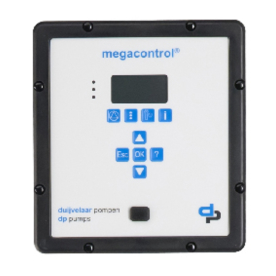
Микропроцессорный модуль управления Megacontrol®
Применение: для оптимизации управления давлением, жокей-насосами, уровнем в емкостях и управления скоростью вращения.
•Megacontrol® – это микропроцессорный модуль управления, который совершенствовался в течение многих лет работы в области производства установок повышения давления.
Megacontrol® имеет широкий диапазон возможностей для программирования и оптимизации управления насосами и насосными системами. Микропроцессор хорошо подходит для управления установками, содержащими до 6 насосов. Модуль программируется при помощи стандартного дисплея. Доступ к программированию может быть ограничен при помощи пароля. Текст и параметры системы постоянно отображаются на жидкокристаллическом дисплее, имеющем 2 строки по 20 символов.
•Установка поставляется в нескольких конфигурациях. Полная документация предоставляется.
Оптимизация регулирования давления
Гибкость программирования Megacontrol® позволяет полностью оптимизировать обычное регулирование давления при помощи предварительной коррекции давления, коррекции требуемого давления и автоматической коррекции времени работы.
Управление жокей-насосами
Установка содержит один или более рабочих насосов, которые обеспечивают подачу необходимого количества воды. Жокей-насос поддерживает требуемое давление и дает необходимое количество воды, пока рабочие насосы не включатся в работу.
Когда последний рабочий насос выключится, жокей-насос вновь вступит в работу для поддержания остаточного расхода воды и будет работать до достижения заданного предельного давления.
Управление уровнем в емкостях для хранения воды
При наличии датчика уровня или манометра в емкости уровень воды в ней может контролироваться при помощи следующих функций:
•сигнал переполнения;
•открытие/закрытие 1-го клапана подачи;
•открытие/закрытие 2-го клапана подачи;
•сигнал о критическом уровне воды;
•сброс защиты от «сухого» хода;
•защита от «сухого» хода и другая сигнализация.
Спецификация оборудования
Система с микропроцессорным управлением используется для установок, содержащих до 6 насосов. Модуль предназначен для установки на панели управления и может быть снабжен интерфейсом RS232 для перепрограммирования и связи с внешними устройствами.
Панель управления исполнения IP54 подключается к модулю при помощи коаксиального кабеля.
Модуль управления отвечает стандарту VOE110 и безопасен при работе при температуре окружающей среды до 50 °С и относительной влажности 20-90 % (без конденсата).
Панель управления снабжена 9 кнопками с уплотнением из фольги. Две кнопки снабжены светодиодами для рабочей и аварийной индикации. Жидкокристаллический дисплей имеет 4 строки по 20 символов.
|
*Компания оставляет за собой право вносить конструктивные изменения |
|
|
Компания АДЛ производство и поставки промышленного оборудования |
49 |
Тел.: (495) 937 8968 Факс: (495) 933 8501/02 info@adl.ru www.adl.ru интернет-магазин: www.valve.ru

Каталог «Насосное оборудование фирмы DP-PUMPS»
Возможна установка второго дисплея в другом месте установки при помощи интерфейса P8485. Соединение с компьютером управляющей системы возможно посредством интерфейса RS232. Для реализации этой возможности необходимо наличие протокола обмена.
Измеритель давления должен быть откалиброван в процентах от уровня воды. На дисплее количество открытых клапанов отображается цифрами 0, 1 или 2.
Управление скоростью вращения
Управляемый пребразователем частоты насос поддерживает давление до достижения максимальной скорости, после чего включается следующий насос. Это повторяется до тех пор, пока не включатся все насосы.
При снижении расхода скорость насоса, управляемого преобразователем частоты, снижается. При достижении этим наосом минимальной скорости вращения насосы с постоянной скоростью будут поочередно отключаться.
Установка, управляемая преобразователем частоты, будет постоянно поддерживать заданное значение, пока управляющий сигнал не будет постоянным в течение определенного времени. После этого задание повышается на установленное значение и установка выключается. (При повышенном давлении расширительный бак заполняется для компенсации небольшого расхода в то время, пока установка не работает). Megacontrol® может увеличить или уменьшить задание на установленное значение при включении и выключении насосов для корректировки потерь давления при увеличении расхода.
Установка с преобразователем частоты работает внутри настроенного интервала (гистерезис). При получении сигнала аварии от преобразователя установка переходит на аварийный режим работы, при котором насосы включатся и выключатся при достижении границ петли гистерезиса. Этот режим автоматически оптимизируется модулем Megacontrol®.
Управлене потоком
|
*Компания оставляет за собой право вносить конструктивные изменения |
|||||||||||||||||||||||||||||||||||||||||
|
50 |
Компания АДЛ производство и поставки промышленного оборудования |
Тел.: (495) 937 8968 Факс: (495) 933 8501/02 info@adl.ru www.adl.ru интернет-магазин: www.valve.ru

Каталог «Насосное оборудование фирмы DP-PUMPS»
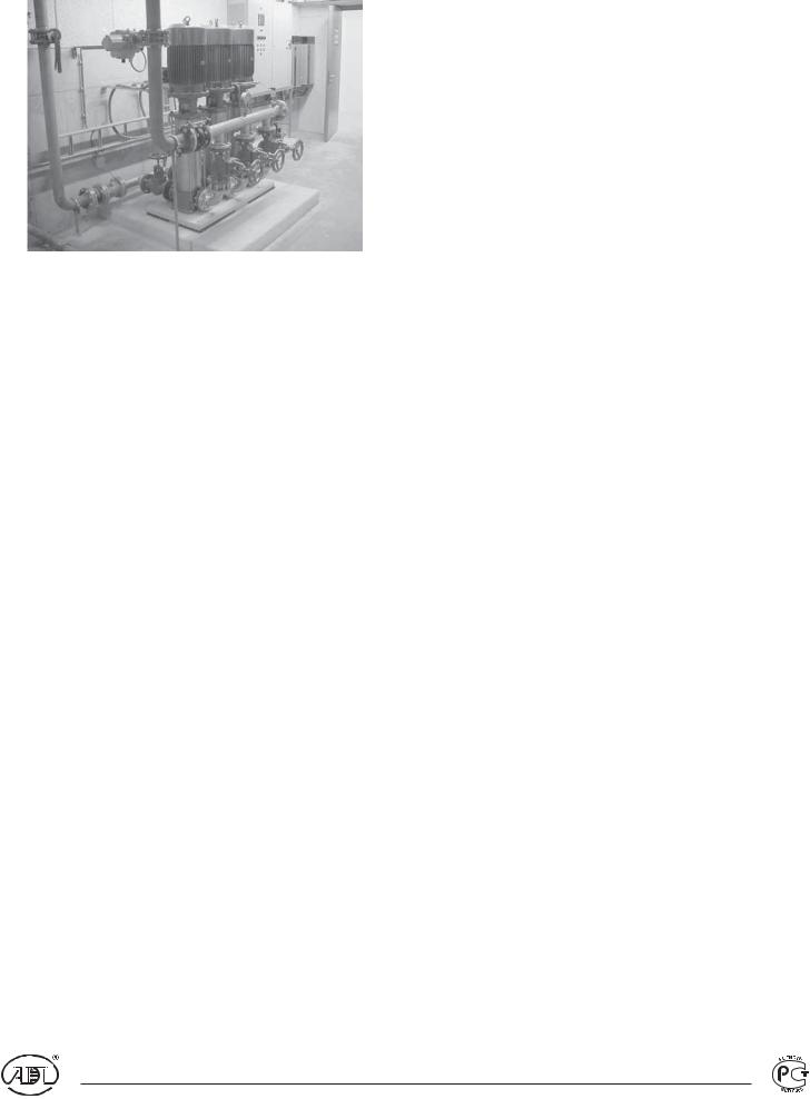
Станция повышения давления Hуdro-Unit с переменной скоростью вращения
Для оптимального управления
Применение: для подачи питьевой воды в высотных зданиях, подачи технологической воды, а также в системах, предъявляющих высокие требования к параметрам станций повышения давления.
•Станция Hydro-Unit с преобразователем частоты является комплектной установкой для питьевой или технологической воды. Станция может использоваться в системах с высокими требованиями к управлению и поддержанию давления.
•Станция повышения давления Hуdro-Unit поставляется полностью собранной, настроенной и проверенной на заводе. Необходимо лишь присоединить ее к трубопроводу и подключить к электросети.
|
• |
Станция повышения давления производится |
|
в соответствии с самыми высокими стандартами. |
•Установка поставляется в нескольких конфигурациях. Полная документация предоставляется.
•DP-Pumps имеет богатый опыт, накопленный за многие годы выпуска этого типа оборудования, поэтому установки отвечают самым высоким стандартам качества и обслуживания.
•Постоянная связь с сервисной службой станций Hydro-Unit позволяет делать установку максимально удобной в обслуживании.
Насосы
Вертикальный многоступенчатый центробежный насос производства DP-Pumps. Гидравлические части насоса изготовлены из высококачественной нержавеющей стали, что снижает потребление энергии, стоимость оборудования и повышает долговечность. Для более подробной информации используйте документацию по соответствующим насосам.
Двигатели
Насосы укомплектованы обычными двигателями стандарта IEC, поэтому при использовании преобразователя частоты они могут работать на полную мощность.
Обратный клапан
Подпружиненный.
Отсечные клапаны
Установлены на входе и выходе каждого насоса.
Коллекторы
К насосам подключены коллекторы из меди или нержавеющей стали.
Датчик давления
Высококачественный датчик давления с выходным аналоговым сигналом 4-20 мА.
Расширительный бак с мембраной
Бак снабжен мембраной, которая не выделяет токсичных веществ и не влияет на вкус и запах воды. Поэтому данная установка может применяться для подачи питьевой воды. Максимальное рабочее давление – 1000 кПа.
Преобразователь частоты
Преобразователь частоты имеет систему управления VVC, что обеспечтвает минимизацию потерь в двигателе при максимальной эффектиности. Использование настраиваемых характеристик отношения момент/скорость дает очень точное управление давлением и высокую степень сохранения энергии. Благодаря низкой частоте коммутации минимизируется влияние преобразователя на сеть.
|
*Компания оставляет за собой право вносить конструктивные изменения |
|
|
Компания АДЛ производство и поставки промышленного оборудования |
51 |
Тел.: (495) 937 8968 Факс: (495) 933 8501/02 info@adl.ru www.adl.ru интернет-магазин: www.valve.ru

Каталог «Насосное оборудование фирмы DP-PUMPS»
Панель управления
Стальная панель управления с эпоксидным покрытием исполнения IP54 снабжена всем необходимым:
•оптимальной защитой двигателя;
•контролем одинакового времени работы и ограничителем количества пусков в час для каждого насоса.
•штатной и аварийной сигнализацией;
•контактами для подключения устройства защиты от «сухой» работы.
Основание
Толстолистовая сталь, покрытая эпоксидной смолой.
|
*Компания оставляет за собой право вносить конструктивные изменения |
|
|
52 |
Компания АДЛ производство и поставки промышленного оборудования |
Тел.: (495) 937 8968 Факс: (495) 933 8501/02 info@adl.ru www.adl.ru интернет-магазин: www.valve.ru

|
ru.info@adl 8501/02 933 (495) Факс: 8968 937 (495) :.Тел |
промышленного поставки и производство АДЛ Компания |
изменения конструктивные вносить право собой за оставляет Компания* |
|
-интернет ru.adl.www |
оборудования |
|
|
valve.www магазин: |
||
|
ru. |
||
53
|
Модель |
Размеры, мм |
||||||||||
|
L1 |
L2 |
*B1 |
B2 |
*B3 |
*B4 |
*B5 |
H1 |
*H2 |
H3 |
||
|
HU2 DPV 2 EX 1″ 35 |
945 |
65 |
-20 |
450 |
90 |
500 |
610 |
100 |
— |
1250 |
|
|
HU3 DPV 2 EX 1″ 42 |
1220 |
65 |
-5 |
450 |
60 |
510 |
670 |
100 |
— |
1250 |
|
|
HU2 DPV 4 EX 1¼» 42 |
945 |
65 |
-10 |
450 |
100 |
525 |
720 |
100 |
— |
1250 |
|
|
HU3 DPV 4 EX 1¼» 54 |
1220 |
65 |
15 |
450 |
145 |
575 |
665 |
100 |
— |
1250 |
|
|
HU4 DPV 4 EX 1¼» 67 |
1540 |
65 |
20 |
450 |
155 |
590 |
750 |
100 |
— |
1250 |
|
|
HU2 DPV 10 EX 1½» 54 |
945 |
65 |
40 |
450 |
175 |
640 |
695 |
130 |
— |
1250 |
|
|
HU3 DPV 10 EX 1½» 67 |
1220 |
65 |
45 |
450 |
190 |
650 |
710 |
130 |
— |
1250 |
|
|
HU4 DPV 10 EX 1½» 80 |
1540 |
65 |
55 |
450 |
205 |
665 |
800 |
130 |
— |
1250 |
|
|
HU2 DPV 14 EX 1¼» 42 |
945 |
65 |
180 |
450 |
155 |
615 |
675 |
130 |
— |
1250 |
|
|
HU3 DPV 14 EX 1¼» 54 |
1220 |
65 |
35 |
450 |
165 |
625 |
685 |
130 |
— |
1250 |
|
|
HU4 DPV 14 EX 1¼» 67 |
1540 |
65 |
45 |
450 |
180 |
640 |
775 |
130 |
— |
1250 |
|
|
HU2 DPV 18 EX 2″ 67 |
1220 |
100 |
105 |
450 |
65 |
575 |
680 |
140 |
500 |
1250 |
|
|
HU3 DPV 18 EX 2″ 80 |
1540 |
100 |
110 |
450 |
65 |
580 |
685 |
140 |
510 |
1250 |
|
|
HU4 DPV 18 EX 2″ 106 |
1860 |
100 |
125 |
450 |
65 |
595 |
700 |
140 |
520 |
1250 |
|
|
HU2 DPV 24 EX 2½» 80 |
1220 |
100 |
135 |
450 |
95 |
620 |
720 |
155 |
565 |
1250 |
|
|
HU3 DPV 24 EX 2½» 106 |
1540 |
100 |
150 |
450 |
95 |
635 |
750 |
155 |
580 |
1250 |
|
|
HU4 DPV 24 EX 2½» 139,7 |
1860 |
100 |
165 |
450 |
95 |
650 |
770 |
155 |
595 |
1250 |
|
|
HU2 DPV 32 EX 2½» 80 |
1220 |
100 |
135 |
450 |
95 |
620 |
720 |
155 |
565 |
1250 |
|
|
HU3 DPV 32 EX 2½» 106 |
1540 |
100 |
150 |
450 |
95 |
635 |
750 |
155 |
580 |
1250 |
|
|
HU4 DPV 32 EX 2½» 139,7 |
1860 |
100 |
165 |
450 |
95 |
650 |
770 |
155 |
595 |
1250 |
|
|
HU2 DPV 45 EX 3″ 106 |
1220 |
100 |
155 |
450 |
105 |
650 |
775 |
155 |
615 |
1250 |
|
|
HU3 DPV 45 EX 3″ 139,7 |
1540 |
100 |
170 |
450 |
105 |
665 |
790 |
155 |
630 |
1250 |
|
|
HU4 DPV 45 EX 3″ 168,3 |
1860 |
100 |
185 |
450 |
105 |
680 |
805 |
155 |
645 |
1250 |
|
Примечание. *Допуски размеров 15 мм.
PUMPS»-DP фирмы оборудование «Насосное Каталог
Каталог «Насосное оборудование фирмы DP-PUMPS»
Пожарные станции FU3
Применение: в Голландии данные насосные станции применяются для зданий высотой более 50 м. Для зданий подобного типа обычно очень трудно бороться с крупным пожаром. Одной из причин этого является то, что двигатели пожарных машин не могут создать достаточное давление для обеспечения водой всего здания. Следовательно, эти здания оснащаются системой пожарных трубопроводов и пожарными насосными станциями.
Наиболее общим является применение насосов с частотными преобразователями для каждого насоса. Обычная установка (показана на рисунке) состоит из 3 насосов: 2 обеспечивают требуемую производительность, 1 находится в резерве. Трубопровод всегда закрывается посредством клапана с электроприводом, расположенного на напорном трубопроводе, только в случае пожара клапан автоматически открывается.
Производительность/давление
Обычно каждый этаж имеет один пожарный ввод, который должен обеспечить расход – 600 л/мин. В зданиях без спринклерных систем необходимо предусматривать 2 пожарных ввода одновременно. Это означает, что общая производительность должна быть 1200 л/мин (72 м3/ч).
Минимальное давление на каждом пожарном вводе должно составлять 500 кПа (5 бар), но не может быть больше 700 кПа (7 бар). На каждые 7 этажей (около 25 м) насосы должны обеспечивать различное давление, в зависимости от того, на каком этаже пожарная тревога.
Панель управления
Панель управления состоит из следующих позиций:
•микропроцессорное устройство управления;
•сигнальные лампы «насос в работе» для каждого насоса;
•сигнальные лампы «неисправность» для каждого насоса;
•потенциометр для настройки давления насосов вручную;
•кнопки для каждой зоны для включения насосов допущенным персоналом;
•кнопка «стоп» для выключения установки после пожара;
•кнопка для проверки сигнальных ламп;
•таймер для проверочного пуска (5 минут каждые 24 часа);
•главный выключатель;
•пускатели двигателей;
•защитные реле двигателей;
•выходы для защиты от «сухой» работы;
•выходы для клапана на напоре.
|
*Компания оставляет за собой право вносить конструктивные изменения |
|
|
54 |
Компания АДЛ производство и поставки промышленного оборудования |
Тел.: (495) 937 8968 Факс: (495) 933 8501/02 info@adl.ru www.adl.ru интернет-магазин: www.valve.ru

Каталог «Насосное оборудование фирмы DP-PUMPS»
Подача воды
Для такого типа установки необходима большая подача воды (72 м3/ч). Хорошим решением является установка большого бака с вместимостью, достаточной для обеспечения работы установки как минимум в течение часа.
Работа установки в случае пожарной тревоги
В случае пожара установка включается допущенным лицом из пожарной бригады. Скорость вращения насосов зависит от того, на каком этаже (в какой зоне) была активирована пожарная система. Эта информация отображается на панели управления. Выбор зоны может быть сделан с помощью соответствующих кнопок. После активации этой кнопки насосы начнут работать. Посредством потенциометра выходное давление может быть скорректировано в пределах 10 %. При включением установки клапан автоматически откроется. После погашения пожара установка должна быть выключена кнопкой «стоп» и вся вода должна быть слита. После этого, установка снова находится в резерве.
Описание типичной установки
Пожарная установка, тип FU3 DPL 45 — …Ex/S DN80 114,3 mm.
Полностью собрана и включает в себя:
•3 насоса DPL, 3 фазн. 400/692 В, 50 Гц, 2850 об/мин;
•3 частотных преобразователя;
•1 панель управления DKVO 730 S (упоминалась выше);
•1 датчик давления Pу 25;
•3 клапана на входе Ду 80 Pу 10 ;
•3 клапана на напоре Ду 80 Pу 25;
•3 обратных клапана Ду 80 Pу 25;
•1 трубопровод на входе 114,3 мм, нержавеющая сталь, с фланцами Ду 100;
•1 напорный трубопровод 114,3 мм, нержавеющая сталь Pу 25, с фланцами Ду 100;
•1 клапан с электроприводом Ду 100 Pу 25, установленный на напорном трубопроводе;
•1 трубопровод 1″ для ежедневной проверки с соленоидным клапаном для подачи воды обратно в бак;
•1 опорная плита, покрытая эпоксидом.
Частотные преобразователи и панель управления поставляются отдельно.
|
*Компания оставляет за собой право вносить конструктивные изменения |
|
|
Компания АДЛ производство и поставки промышленного оборудования |
55 |
Тел.: (495) 937 8968 Факс: (495) 933 8501/02 info@adl.ru www.adl.ru интернет-магазин: www.valve.ru

Каталог «Насосное оборудование фирмы DP-PUMPS»
Встроенный преобразователь частоты с ПИД-регулятором М1
Применение: в станциях повышения давления с очень высокими требованиями к стабильности давления, а также в составе других установок для оптимизации работы насосов.
Преобразователь применяется также в:
станциях повышения давления Hydro-Unit;
системах с одним насосом;
станциях повышения давления с 2 или 3 насосами под управленим DP-Control;
•станциях повышения давления от 1 до 6 насосов
вразличных конфигурациях под управлением Megacontrol®;
•вертикальных насосах серий DPV и DPL;
•горизонтальных насосах серии DPH.
•Преобразователь частоты со встроенным ПИД регулятором, настроен на применение со стандартными насосами DP-Pumps®.
•Преобразователь частоты соответствует стандарту ЕМС для высотных зданий (кривая В).
•Преобразователь частоты имеет очень низкий уровень шума в результате применения высокой частоты коммутации.
•Преобразователь снабжен потенциометром для ручной регулировки и светодиодами для рабочей и аварийной сигнализации.· Полное программирование осуществляется через интерфейс.
Настройка/работа
Преобразователь имеет отдельно поставляемый интерфейс для работы, программирования и индикации рабочих параметров. Информация отображается на 4-строчном жидко-кристаллическом дисплее. 10 различных установок (запрограммированных параметров), которые можно менять при помощи функций интерфейса «считывание» и «загрузка». Программное обеспечение, работающее в среде Windows, позволяет считывать и менять параметры с помощью компьютера.
Двигатель/преобразователь
Двигатели стандарта IEC со специальным адаптером и преобразователем частоты.
При неисправности в двигателе или преобразователе нет необходимости в замене всей установки.
Основные технические характеристики
|
Окружающая температура |
-10 °С – +50 °С |
|
Мощность |
0,37–7,5 кВт |
|
Максимальная температура |
95 °С |
|
Частота коммутации |
16 кГц |
|
Исполнение корпуса |
IP65 |
|
*Компания оставляет за собой право вносить конструктивные изменения |
|
|
56 |
Компания АДЛ производство и поставки промышленного оборудования |
Тел.: (495) 937 8968 Факс: (495) 933 8501/02 info@adl.ru www.adl.ru интернет-магазин: www.valve.ru

Каталог «Насосное оборудование фирмы DP-PUMPS»
Расширительные баки для водоснабжения
Расширительный бак Airfix
Применение: аккумуляторная емкость в системах водоснабжения, а так же, для компенсации температурных расширений теплоносителя в системах отопления.
Основные технические характеристики
|
Максимальное рабочее давление |
10 бар |
|
Максимальная температура |
120 °С |
|
Рабочая температура |
70 °С |
Расширительные баки объемами от 8 до 33 литров включительно (Airfix A) комплектуются пластиковым присоединением для возможности подключения бака «в проток». Это позволяет избежать застоя жидкости в баке.
Параметры расширительных баков Airfix
|
Марка |
Предварительное давление, бар |
Коэффициент заполнения, % |
|
Airfix 2 |
||
|
Airfix 4 |
||
|
Airfix 8 |
4 |
60 |
|
Airfix 12 |
||
|
Airfix 18 |
||
|
Airfix 25 |
||
|
Airfix 35 |
||
|
Габаритные размеры, мм |
Присоединение, внешняярезьба |
Максимальное рабочеедавление,бар |
||
|
Масса,кг |
||||
|
D |
H |
|||
|
194 |
154 |
3/ « |
1,2 |
5 |
|
4 |
||||
|
194 |
258 |
3/ « |
1,7 |
5 |
|
4 |
||||
|
245 |
303 |
3/ « |
3,8 |
10 |
|
4 |
||||
|
286 |
334 |
3/ « |
5,1 |
10 |
|
4 |
||||
|
328 |
327 |
3/ « |
6,4 |
10 |
|
4 |
||||
|
358 |
379 |
3/ « |
7,6 |
8 |
|
4 |
||||
|
396 |
436 |
3/ « |
10 |
6 |
|
4 |
|
Обычное присоединение |
Присоединение «в проток» |
|
*Компания оставляет за собой право вносить конструктивные изменения |
|
|
Компания АДЛ производство и поставки промышленного оборудования |
57 |
Тел.: (495) 937 8968 Факс: (495) 933 8501/02 info@adl.ru www.adl.ru интернет-магазин: www.valve.ru

Каталог «Насосное оборудование фирмы DP-PUMPS»
Расширительный бак Airfix D-E
Применение: аккумуляторная емкость в системах водоснабжения, а также для компенсации температурных расширений теплоносителя в системах отопления.
|
Основные технические характеристики |
Возможна комплектация: |
|
Максимальное рабочее давление |
10/16 бар |
|
Максимальная температура |
120 °С |
|
Рабочая температура |
70 °С |
двойным или одинарным присоединением;
датчиком разрыва мембраны.
Параметры расширительных баков Airfix D-E
|
Габаритные размеры, мм |
||||||
|
Марка |
||||||
|
D |
H |
a |
e |
d |
||
|
Airfix D-E 50 |
450 |
845 |
320 |
190 |
470 |
|
|
Airfix D-E 80 |
450 |
1025 |
320 |
190 |
470 |
|
|
Airfix D-E 120 |
450 |
1280 |
320 |
190 |
470 |
|
|
Airfix D-E 180 |
550 |
1235 |
320 |
185 |
565 |
|
|
Airfix D-E 240 |
550 |
1495 |
320 |
185 |
565 |
|
|
Airfix D-E 300 |
550 |
1835 |
320 |
185 |
565 |
|
|
Airfix D-E 600 |
750 |
1850 |
390 |
140 |
680 |
|
|
Airfix D-E 800 |
750 |
2240 |
390 |
140 |
680 |
|
|
Airfix D-E 1000 |
750 |
2740 |
390 |
140 |
680 |
|
|
Airfix D-E 1600 |
1000 |
2670 |
370 |
260 |
690 |
|
|
Airfix D-E 2000 |
1200 |
2420 |
370 |
280 |
840 |
|
|
Airfix D-E 3000 |
1200 |
3320 |
370 |
280 |
540 |
|
|
*Компания оставляет за собой право вносить конструктивные изменения |
||||||
|
58 |
Компания АДЛ производство и поставки промышленного оборудования |
|
Присоединение, фланец Pу 16 |
Масса, кг |
|
Ду 40 |
60 |
|
Ду 40 |
70 |
|
Ду 40 |
80 |
|
Ду 40 |
110 |
|
Ду 40 |
130 |
|
Ду 40 |
150 |
|
Ду 50 |
230 |
|
Ду 50 |
270 |
|
Ду 50 |
320 |
|
Ду 80 |
550 |
|
Ду 80 |
620 |
|
Ду 80 |
805 |
Тел.: (495) 937 8968 Факс: (495) 933 8501/02 info@adl.ru www.adl.ru интернет-магазин: www.valve.ru
Соседние файлы в папке Каталоги и проспекты
- #
- #
- #
- #
- #
- #
- #
- #

Control unitsInstallation and operating instructions
Series: Megacontrol

2
Table of Contents
1 Introduction1.1 Preface………………………………………………………………………………………………………………………………… 41.2 Icons and symbols ………………………………………………………………………………………………………………… 4
2 Identification, service and technical support2.1 Identification, service and technical support ……………………………………………………………………………… 52.2 Supplementary documentation ……………………………………………………………………………………………….. 5
3 Warranty3.1 Terms of warranty …………………………………………………………………………………………………………………. 6
4 Safety and environment4.1 General ……………………………………………………………………………………………………………………………….. 74.2 Environmental aspects…………………………………………………………………………………………………………… 7
5 Introduction5.1 General ……………………………………………………………………………………………………………………………….. 85.2 Intended use ………………………………………………………………………………………………………………………… 85.3 Working range………………………………………………………………………………………………………………………. 85.4 Functioning ………………………………………………………………………………………………………………………….. 9
6 Transport6.1 Transport and storage………………………………………………………………………………………………………….. 10
7 Installation7.1 Mechanical installation…………………………………………………………………………………………………………..117.2 Electrical installation ……………………………………………………………………………………………………………..117.3 Commissioning …………………………………………………………………………………………………………………… 12
8 Operation8.1 Control panel (HMI)……………………………………………………………………………………………………………… 138.2 Manual operation of the pumps …………………………………………………………………………………………….. 158.3 Retrieve and reset a fault……………………………………………………………………………………………………… 16
9 Hydro-unit configuration9.1 Hydro-Unit MC ……………………………………………………………………………………………………………………. 189.2 Hydro-Unit MC ++ ……………………………………………………………………………………………………………….. 199.3 Hydro-Unit MCJ ………………………………………………………………………………………………………………….. 209.4 Hydro-Unit MCF ………………………………………………………………………………………………………………….. 219.5 Hydro-Unit MCMF ……………………………………………………………………………………………………………….. 229.6 Hydro-Unit Level control ………………………………………………………………………………………………………. 239.7 Explanation of parameters ……………………………………………………………………………………………………. 23
10 Parameters10.1 Parameter list……………………………………………………………………………………………………………………… 26
11 Faults11.1 Failure messages Megacontrol……………………………………………………………………………………………… 4211.2 Failure messages Danfoss VFD ……………………………………………………………………………………………. 43

3
12 Annexes12.1 Megacontrol ……………………………………………………………………………………………………………………….. 4712.2 Built-in diagram…………………………………………………………………………………………………………………… 4812.3 Electrical connections ………………………………………………………………………………………………………….. 4812.4 EC Declaration of conformity ………………………………………………………………………………………………… 51

4
1 Introduction
1.1 Preface
This manual contains important information for reliable, proper and efficient operation. Compliance with the operating instructions is of vital importance to ensure reliability and a long service life of the product and to avoid any risks.The first chapters contain information about this manual and safety in general. The following chapters provide information about normal use, installation, maintenance and repairs of the product. The annex contains the declaration(s) of conformity.
• Make yourself familiar with the content.• Accurately follow the directions and instructions.• Never change the sequence of the operations to
be carried out.• Keep this manual or a copy of it together with the
logbook in a fixed place near the product which can be accessed by all personnel.
1.2 Icons and symbols
In this manual and in all accompanying documentation the following icons and symbols are used.
WARNINGDanger of electric Voltage. Safety sign according to IEC 417 — 5036
WARNINGOperations or procedures, if carried out without caution, may cause personal injury or damage to the product. General hazard sign according to ISO 7000-0434
ATTENTIONIs used to introduce safety instructions whose non-observance may lead to damage to the product and its functions.
ENVIRONMENTAL INSTRUCTIONRemarks with respect to the environment.
READ THE (SUPPLEMENTARY) DOCUMENTATIONRead the user and operating instructions.

5
2 Identification, service and technical support
2.1 Identification, service and technical support
The system is identified based on the text “Megacontrol” as given on the front of the system.Table 1: Control unit
The following address data are available for service and technical support:Table 2: Address service department
2.2 Supplementary documentation
This version is valid from Megacontrol version V1.57. Apart from this manual, the additional documentation given below is available as well:Table 3: Supplementary documentation
Table 4: Megacontrol versions
Indication MeaningMegacontrol Type of Control unit
DP-Pumps
Kalkovenweg 132401 LJ Alphen a/d RijnThe Netherlands
Tel: +31 172 488388Fax: +31 172 468930Internet: www.dp-pumps.comE-mail: [email protected]
Document Date/version CodeGeneral terms of delivery 10-1998 119 / 1998Manual WSD-Sensor 11-2009 BE00000250Technical documentationDocumentationAlso see: www.dp-pumps.com
Firm ware version (see parameter: 4-1-3) Manualversion
Megacontrol V 1.27 03-2008Megacontrol V 1.36 10-2009Megacontrol V 1.43 06-2011Megacontrol V 1.52 01-2013Megacontrol V 1.57 01-2014Also see: www.dp-pumps.com

6
3 Warranty
3.1 Terms of warranty
The warranty period is settled by the terms of your contract or at least by the general terms and conditions of sales.
ATTENTIONModifications or alterations of the product supplied are only permitted after consultation with the manufacturer. Original spare parts and accessories authorized by the manufacturer ensure safety. The use of other parts can invalidate any liability of the manufacturer for consequential damage.
ATTENTIONThe warranty relating to the operating reliability and safety of the product supplied is only valid if the product is used in accordance with its designated use as described in the following sections of this manual. The limits stated in the data sheet must not be exceeded under any circumstances.
The warranty becomes invalid if one or more of the points below occur.• The buyer makes modifications himself.• The buyer carries out repairs himself or has
these carried out by a third party.• The product has been handled or maintained
improperly.• The product has non original DP-Pumps spare
parts fitted.
DP-Pumps repairs defects under warranty when:
• They are caused by flaws in the design, the material or the production.
• They are reported within the warranty period.Other terms of warranty have been included in the general terms of delivery, which are available upon request.

7
4 Safety and environment
4.1 General
This DP-Pumps product has been developed using state-of-the-art technology; it is manufactured with utmost care and subject to continuous quality control.DP-Pumps does not accept any liability for damage and injury caused by not observing the directions and instructions in this manual, or in cases of carelessness during the installation procedure, use and maintenance of the product.Non-compliance with safety instructions can jeopardize the safety of personnel, the environment and the product itself. Non-compliance with these safety instructions will also lead to forfeiture of any and all rights to claims for damages. For example, in particular non-compliance can result in:
• failure of important pump/system functions,• failure of prescribed maintenance and servicing
practices,• injury to persons by electrical, mechanical and
chemical effects,• hazard of the environment due to leakage of
hazardous substances,• explosions.
Depending on specific activities, extra safety measures may be required. Contact DP-Pumps if a potential danger arises during use.
ATTENTIONThe owner of the product is responsible for compliance with the local safety regulations and internal company guidelines.
ATTENTIONNot only must the general safety instructions laid down in this chapter on «Safety» be complied with, but also the safety instructions outlined under specific headings.
4.2 Environmental aspects
4.2.1 GeneralThis product of DP-Pumps is designed to function in an environmentally friendly way during their entire life.
ENVIRONMENTAL INSTRUCTIONAlways act according to the laws, by-laws regulations and instructions with respect to health, safety and the environment.
4.2.2 DismantlingDismantle the product and dispose of it in an environmentally friendly way. The owner is responsible for this.
ENVIRONMENTAL INSTRUCTIONAsk at the local government about the re-use or the environmentally friendly processing of discarded materials.
ENVIRONMENTAL INSTRUCTIONAll components of the Megacontrol are manufactured in accordance with RoHS directive 2002/95/EC.

8
5 Introduction
5.1 General
Control units of the type Megacontrol are manufactured by DP-Pumps.
5.2 Intended use
The control unit is suitable for controlling a Hydro-Unit consisting of 1, 2, 3, 4, 5 or 6 pumps within the indicated working range (see “Working range“).
Any other or further use of the control unit is not in conformity with its intended use. DP-Pumps does not accept any liability for any damage or injury resulting from this. The control unit has been produced in accordance with the current standards and guidelines. Use the control unit exclusively in a perfect technical state, in conformity with the intended use described below.
The Intended use as laid down in ISO 12100:2010 is the use for which the technical product is intended according to the specifications of the manufacturer. The use of the product has been described in the available documentation / information. Always observe the instructions given in the installation and operating instructions. When in doubt the product must be used as becomes evident from its construction, version and function.
5.3 Working range
The working range of the control unit can be summarized as follows:
Table 5: Working range of the Megacontrol
Table 6: Specific applications of the Megacontrol
5.3.1 WSD-Sensor (option)
The working range of the WSD-Sensor can be summarized as follows:
Table 7: Working range of the WSD-Sensor
ID2982/07062007
Figure 1: Control units of the type Megacontrol 20
0704
76-A
Type MegacontrolMaximum ambient temperature [°C]
50
Relative atmospheric humidity [%]
20 — 90 (no condensation)
Voltage [V] 1 x 230 V ACFrequency [Hz] 50/60
Type Application areaMegacontrol Building possible in the installations
listed below:• Hydro-Unit® with 1 — 6 pumps• Break-Unit with 1 — 6 pumps• Fire-Unit with 1 — 6 pumps
Type WSD-SensorMaximum ambient temperature [°C] 30Relative atmospheric humidity [%] -Voltage [V] -Frequency [Hz] -Medium temperature [°C] 5 — 30Switching flow [l/min] ± 14

9
Table 8: Specific applications WSD
5.4 Functioning
5.4.1 Standard operation
The Megacontrol is an intelligent control unit for different components of pressurization systems consisting out of a maximum of 6 pumps. The required system pressure is sensed by a pressure sensor on the outlet side of the installation.
When as a result of a decreasing water volume the pressure drops below the pressure set point, a pump will be switched on.
When the required system pressure has been reached, the pumps are switched off one at a time. The minimum run time is optimized constantly, which results in a considerable energy saving.
5.4.2 Custom made settings
The Megacontrol can be programmed through the human machine interface (HMI) operating panel and has been protected against unauthorized use by a password.
Also, the service port provides access to the parameters of the program which can be used to optimize the functionality of the installation, (see: “Parameter list”).
WARNINGFor access to the parameters of the program using the service port, always use the special service port cable!
The special service port cable (Art. nr. 6147117698) can by ordered separately.
5.4.3 Number of operating hours per pump
The current number of operating hours of a pump determines which pump will be switched on or off next. The pump with the fewest operating hours will be switched on first and the pump with the most operating hours will be switched off first. This makes sure that all pumps have an equal number of operating hours, including the backup pump.
5.4.4 Test run
In order to prevent pumps from standing still for a longer period of time, an automatic test run procedure is provided as a standard.
5.4.5 Functioning WSD-Sensor (option)
In combination with the Megacontrol, the WSD can generate a failure message when, during a (adjustable) period of time, insufficient refreshment of the membrane switch vessel occurs.
The failure message is generated when:• Insufficient refreshment occurs;• The membrane of the membrane switch vessel
is defective;• There is no air left in the membrane switch
vessel;• The installation is not set / installed correctly.
5.4.6 Temperature-sensor (option)
When the Megacontrol is fitted with a temperature sensor, it can generate a temperature-dependent failure message.
Type ApplicationsWSD Installations with a maximum of 3
membrane switch vessels.

10
6 Transport
6.1 Transport and storage
1. Transport the control unit in the position as indicated on the pallet or packaging.
2. Check if the control unit is stable.3. Observe the instructions on the packaging (if
present).
ATTENTIONStore the control unit in a dry and dust-free place.

11
7 Installation
7.1 Mechanical installation
ATTENTIONContact the supplier if parts are missing or damaged.
Build in the control unit using suitable fastening material. Consult the annex “Built-in diagram» for the correct overall dimensions.
7.2 Electrical installation
WARNINGOnly authorized personnel is allowed to connect the control unit electrically in accordance with the local regulations.
Electrical connections• Make sure that the electric control unit
specifications correspond with the power supply to which is connected.
• Consult the annex «Electrical diagram» for a list of all electrical power points.
7.2.1 Recommended RS485-termination for MCIII (b)
The new board for MCIII (b) is based on a new hardware platform. One new feature is, that the clamps for the external RS485-bus (J301) will now benefit the advantage of galvanic isolated bus- and GND-lines.
7.2.2 Parameter settings of the frequency converters
By selecting a type of frequency converter in parameter 3-4-3-1 and selecting also the VFD Fixed All configuration in parameter 3-3-3 it will be possible to set the following parameters by Megacontrol.Before setting the parameters: Turn off each pump in parameter 1-2-1. Then set the parameters in the following sequence.
Megacontrol parameter:1 3-4-3-13 P nominal of VFD 2 3-4-3-14 U nominal of VFD 3 3-4-3-15 F nominal of VFD 4 3-4-3-16 I nominal of VFD 5 3-4-3-17 RPM nominal of VFD
After entering these parameters, the other parameters can be set at their discretion. Always check the correct setting of the frequency converters parameters.
A RS485-termination with 1…6 “DANFOSS Micro-Drives”
1 MCIII (b) : keep the termination clamps on the MCIII (b) T+ / T- open
2 Microdrives: switch the bus termination to position on, on each Micro Drive.
B1 RS485-termination with 1…2 “DANFOSS AQUA Drives”
1 MCIII (b) : keep the termination clampson the MCIII (b) T+ / T- open
2 AQUA Drive: switch the bus termination to position on, on each AQUA Drive
B2 RS485-termination with 3…6 “DANFOSS AQUA Drives”
1 MCIII (b) : keep the termination clamps on the MCIII (b) T+ / T- open
2 AQUA Drive: set the bus termination only on the last AQUA Drive
3 External termination: Place, near to the MCIII (b), an external active bus termination, like normally used for Profibus, for example: 6ES7 972-0DA00-0AA01 or FBCon DP M12 Term 24V2
1. Siemens profibus terminator: „6ES7 972-0DA00-0AA0“. http://cache.automation.siemens.com/dnl/DM/DM3NTIxAAAA_19102444_HB/3B_812_6727-10a_Terminator.pdf
2. Weidmüller: „FBCon DP M12 Term 24V“. http://cata-log.weidmueller.com/catalog/Start.do?localeId=de_DE&ObjectID=8564330000

12
7.2.3 Using contactors
ATTENTIONAlways place, using contactors and/or auxiliary relays, a suitable RC filter or varistor across the coil, e.g. Siemens 3RT29-16-1CD00
7.3 Commissioning
The control unit is fully programmed and preset with factory default settings. Use the control panel, or the service port to access the parameters of the program which can be used to optimize the functionality of the installation, (see: “Parameter list”).

13
8 Operation
8.1 Control panel (HMI)
The control panel comprises a back-light display, function, navigation, and operating keys, LED’s, and 2 access points for the service interface. The display shows important information for pump system operation. Data can be displayed in plain text and parameters can be set.
Table 9: Traffic lights
Table 10: Function keys
Table 11: Navigation keys
ID 2944
Figure 2: Front Megacontrol 2014
0253
A: LED’sThe “traffic light” signals provide information about the pump system’s operating status. LED’s:• Red: Alert / urgent alarm is active.• Amber: Warning / non-urgent alarm is active.• Green: O.K. / trouble-free operation.
A
B
C
D
B: Function keysYou can use the function keys to access the elements at the first menu level directly: Operation, Diagnosis, Settings and Information.
Operation
Diagnosis
Settings
Information
C: Navigation keysThe navigation keys are used for navigating in the menu and for confirming settings.
Up or Down • Move up / down through the root
menu (displays the measured values of the system input);
• Move up / down through the menu options or;
• Increase / decrease a value when you are entering numerals.
Escape key • Delete / reset entry (the entry is not
saved);• Return to the previous menu level.
OK key • Access to the quick menu;• Confirm a setting;• Confirm a menu selection.• Go to the next number when you are
entering numerals.Help key• Displays a help text for each selected
menu option.

14
8.1.1 DisplayThe 7-row display contains the following information:ID 2987
Table 12: Display rows
The number of the current menu or parameter is displayed in the top left of the screen. This number indicates the path through the menu levels and, therefore, allows you to quickly locate parameters (see “Parameter list”).
The date and time is displayed in the bottom right of the screen. If a fault occurs, this is displayed in the bottom line and alternating with the date and time.
8.1.2 Continuous display
When in operation the most common values, like the system pressure are shown on the display continuously. By pushing the navigation buttons Up and Down all selected values are passing by. In Parameter setting 3-10 “Root menu” these values can be selected as pre-set value. The selected values are marked with a “ √ “
Table 13: Display example
8.1.2.1 Quick menuHaving access to the most used parameters a Quick menu can be entered by pressing the OK key.
8.1.3 Access levelsTo prevent accidental or unauthorized access to the Megacontrol parameters, various access levels have been defined.
D: Service interfaceThe service interface allows a PC / Notebook to be con-nected with use of the special service port cable. The Meg-acontrol PC software can be used to configure and parameterize the pump system if you do not have access to a control panel. The Megacontrol software can also be updated via this interface. A second service interface is located on the back side of the controller.
Display Meaning1 1-1-1 Displays the selected parame-
ter no.2 Parameter / Function Parameter name,
Function key: • Operation • Diagnosis• Settings • Information
3 Parameter name List of selectable parameters4 Level Operating level:
• All• User• Service • Factory“Scroll bar” within the list of selectable parameters
5 MM-YY 00:00 Current date and time
23
5
4
ID 2955
Display1 1-1-12 System pressure3 5254 kPa5 MM-JJ 00:00
2
35
4

15
Table 14: Access levels
ATTENTIONIf no keys are pressed for ten minutes, the system automatically returns to the default access level.
8.1.4 Displaying and changing parameters The parameter numbers contain the navigation path, which helps you find a particular parameter quickly and easily. The first digit of the parameter number indicates the first menu level, which can be called up directly via the four function keys. Subsequent steps are carried out via the navigation keys.
8.2 Manual operation of the pumps
By pressing the Quick access key “Operation”, information like system pressure and pump load can be retrieved. Also, the pump operating mode like Automatic, Manual and Disabled can be alternated / selected. Subsequent steps are carried out by using the navigation keys.
Access levels: Explanation:Standard Unless users log on to one of the
access levels, they will only have lim-ited access to parameters.
User Access level for expert users. It ena-bles access to all the parameters required for commissioning. You have to enter a password under 3-2-1 “Log in”. The standard password for users is 7353.
Service Access level for service technicians. You have to enter a password under 3-2-1 Log in.
Factory Access level for the manufacturer only.
1—Operation 2—Diagnosis 3—Settings 4—Info
Example: Parameter 3-5-10 Delta P correction:
First digit of parameter number: 3-5-103 Settings 5 Pressure 10 Delta P correction
Press the third function key for Settings. 3-1 appears in the top left of the screen.
Second digit of parameter number: 3-5-103 Settings 5 Pressure 10 Delta P correction
Change the display 3-1 on the screen (top left) to 3-5 by pressing the navigation keys.
To confirm the selection, press OK. 3-5 appears in the top left of the screen.
Third digit of parameter number: 3-5-103 Settings 5 Pressure 10 Delta P correction
Change the display 3-5-1 on the screen (top left) to 3-5-10 by pressing the navigation keys.
To confirm the selection, press OK. 3-5-10 appears in the top left of the screen.
Example: Parameter 1-2-1 (Pumps) Operation mode:
First digit of parameter number: 1-2-11 Operation 2 Pumps 1 Operation mode
Press the first function key for Operation. 1-1 appears in the top left of the screen.
Second digit of parameter number: 1-2-11 Operation 2 Pumps 1 Operation mode
Change the display 1-1 on the screen (top left) to 1-2 by pressing the navigation keys.
To confirm the selection, press OK. 1-2 appears in the top left of the screen.
Third digit of parameter number: 1-2-11 Operation 2 Pumps 1 Operation mode

16
The selected pump will run for a period of 10 seconds and stops. The pump operation mode is changed to Disabled (off) This is to avoid that the pump runs unprotected.
8.2.1 Putting the pump into automatic operation again
The pump has to be put in operation again by selecting the Automatic mode.
8.3 Retrieve and reset a fault
Information about faults can be retrieved by pressing the ‘diagnosis’ hot key
To confirm the selection, press OK. 1-2-1 appears in the top left of the screen.
Select the pump number by pressing the navigation keys.
To confirm the selection, press OK.
Select the operation mode manual (on (10 s)).
To confirm the selection, press OK.
Stay in the selected parameter 1-2-1 Opera-tion mode and press OK.
Select the pump number again by pressing the navigation keys.
To confirm the selection, press OK.
Select the operation mode Automatic.
To confirm the selection, press OK.
Example: Parameter 2-1-1 Current messages
Press the diagnosis key. 2-1 General appears in the display.
Press the OK key. 2-1-1 Current messages appears in the display.
Press the OK key again. The list with the current faults or the message ‘no faults’ appears in the display.
When there is a fault that has a circle with a dot in it, the fault is still active
No Water
When there is a fault that has an open circle, the fault is not active, but has not been acknowledged yet.
No Water
When there is a fault that has a circle with a dot in it and a check mark following the fault message, the fault is still active and the fault has been acknowledged as well. When the fault is remedied now, it will be reset immediately.Example: Parameter 2-1-2 History
Press the diagnosis key. 2-1 General appears in the display.
Press the OK key. The display then shows 2-1-1 Current messages; 2-1-2 History.

17
You can select History by pressing the navi-gation key.
Press the OK key. The list of faults from the past appears.
You can select the fault by pressing the nav-igation key.
Press the OK key. The below listed informa-tion becomes visible.
The following information about the fault is known:• Date and time of occurrence of the fault• Date and time of acknowledgement of the fault• Date and time of remedy of the fault

18
9 Hydro-unit configuration
9.1 Hydro-Unit MC
ATTENTIONSee factory settings 3-2-2-1
When as a result of an increasing water volume the pressure drops below the pressure set point, a pump will be switched on. When the required system pressure has been reached, the pumps are switched off one at a time. The minimum run time related switch-off delay is optimized constantly, which results in a considerable energy saving.
Table 15: Specific parameter settings MC
Figure 3: 1 pump operation
Figure 4: 2 pump operation
Figure 5: 3 pump operation
Q
H
S
Q
H
S
Q
H
S
Parameter Value3-3-1 Number of pumps 1
23456
3-3-2 Inlet SwitchPressureLevel / valve ON-OFFLevel / valve prop.
3-3-3 Discharge Fixed Speed3-5-1 Set point 400 kPa3-5-3 Bandwidth 303-6-2 Min. run time Default 180 s
DOL ≤ 2.2 kW 90 s3-6-3 Min. run time corr. 10 s3-6-8 Run-dry delay Default 30
Float/level control 1

19
9.2 Hydro-Unit MC ++
ATTENTIONSee factory settings 3-2-2-1
When as a result of a increasing water volume the pressure drops below the pressure set point, a pump will be switched on. When the required system
pressure has been reached, the pumps are switched off one at a time. The minimum run time related switch-off delay is optimized constantly, which results in a considerable energy saving.
Table 16: Specific parameter settings MC ++
Figure 6: 1 pump operation
Figure 7: 2 pump operation
Figure 8: 3 pump operation
Parameter Value3-3-1 Number of pumps 1
23456
3-3-2 Inlet SwitchPressureLevel / valve ON-OFFLevel / valve prop.
3-3-3 Discharge Fixed Speed3-5-1 Set point …. kPa3-5-3 Bandwidth 503-5-13 Low pressure alarm 100 kPa3-6-2 Min. run time 1 s3-6-3 Min. run time cor. 10 s3-6-8 Run-dry delay Default 30
Float/level control 1

20
9.3 Hydro-Unit MCJ
ATTENTIONSee factory settings 3-2-2-1
The Hydro-Unit MCJ is fitted with a jockey pump, especially suited for installations with strongly fluctuating water consumption. The jockey pump is a smaller pump with less capacity but the same pressure as the main pumps of the installation. The jockey pump will be started first. If the water consumption is larger than the capacity of the jockey pump, one or more main pumps will be switched on, whereas the jockey pump is switched off. If the capacity of the main pumps is not sufficient, in case of a large water consumption, the jockey pump will also be switched on. A Hydro-Unit can also be fitted with 2 jockey pumps which are each other’s backups.
Table 17: Specific parameter settings MCJ
Figure 9: 1 jockey pump operation
Figure 10: 1 main pump operation
Figure 11: 2 main pumps operation
Q
H
S
S
Q
H
S
Q
H
Parameter Value3-3-1 Number of pumps 1
23456
3-3-2 Inlet SwitchPressureLevel / valve ON-OFFLevel / valve prop.
3-3-3 Discharge One Jockey3-5-1 Set point …. kPa3-5-3 Bandwidth 303-6-2 Min. run time Default 180 s
DOL ≤ 2.2 kW 90 s3-6-3 Min. run time corr. 10 s3-6-8 Run-dry delay Default 30 s
Float/level control 1 s

21
9.4 Hydro-Unit MCF
ATTENTIONSee factory settings 3-2-2-1
The Hydro-Unit MCF is equipped with one variable frequency drive. If the Hydro-Unit is rotation-controlled, the required system pressure is sensed by a pressure sensor on the outlet side of the installation. An integrated adjustable PID-controller in the software of the Megacontrol ensures that the system pressure remains constant by successively switching on or off one or more (whether or not) rotation-controlled pumps with delay. A pump is only switched on when 100% or respectively 0% of the speed has been reached.
Table 18: Specific parameter settings MCF
Figure 12: 1 pump operation, 1 pump variable
Figure 13: 2 pump operation, 1 pump variable
Figure 14: 3 pump operation, 1 pump variable
Parameter Value3-3-1 Number of pumps 1
23456
3-3-2 Inlet SwitchPressureLevel / valve ON-OFFLevel / valve prop.
3-3-3 Discharge VFD change-over3-4-3-1 Communication Analog 0-20 mA3-4-3-2 Proportional const. 603-4-3-3 Integral const. 203-5-1 Set point …. kPa3-5-3 Bandwidth 53-5-4 Accumulation press. 30 kPa3-6-2 Min. run time 1 s3-6-3 Min. run time corr. 0 s3-6-8 Run-dry delay Default 30
Float/level control

22
9.5 Hydro-Unit MCMF
ATTENTIONSee factory settings 3-2-2-1
The Hydro-Unit MCMF is equipped with multiple variable frequency drives. If the Hydro-Unit is rotation-controlled, the required system pressure is sensed by a pressure sensor on the outlet side of the installation. An integrated adjustable PID-controller in the software of the Megacontrol ensures that the system pressure remains constant by successively switching on or off one or more (whether or not) rotation-controlled pumps with delay. A pump is only switched on when 100% or respectively 0% of the speed has been reached.
Table 19: Specific parameter settings MCMF
Figure 15: 1 pump operation, 1 pump variable
Figure 16: 2 pump operation, 2 pump variable
Figure 17: 3 pump operation, 3 pump variable
Parameter Value3-3-1 Number of pumps 1
23456
3-3-2 Inlet SwitchPressureLevel / valve ON-OFFLevel / valve prop.
3-3-3 Discharge VFD fixed all3-4-3-1 Communication Analog 4-20mA
Danfoss VLT 2800PumpDriveDanfoss MicroDriveDanfoss AquaDrive
3-4-3-2 Proportional const. 203-4-3-3 Integral const. 53-4-3-4 Differential const. 13-4-3-5-1 No flow detection
0-1000 kPa10
0-2500 kPa 203-4-3-5-3 No flow step 53-4-3-7 VFD Write slave nr. ID3-4-3-8 Serial com. active. Active3-5-1 Set point …. kPa3-5-3 Bandwidth 103-5-4 Accumulation press. 30 kPa3-5-13 Low pressure alarm 100 kPa3-6-2 Min. run time 10 s3-6-3 Min. run time corr. 0 s3-6-8 Run-dry delay Default 30
Float/level control 1

23
9.6 Hydro-Unit Level controlID2962/29052007
Figure 18: Megacontrol Level controlTable 20: Parameters supply valve ON/OFF
Table 21: Parameters supply valve prop.
Table 22: Parameters general.
Table 23: Parameters threshold
9.7 Explanation of parameters
9.7.1 Pressure settings set points
Figure 19: Pressure settings set points fixed speed Table 24: Pressure settings set points fixed speed
Table 25: Pressure settings set points variable speed
ID Parameter3-4-1-4-9 Supply valve ON/OFF
A 3-4-1-4-7 High water levelB 3-4-1-4-9-2 Level 1 closed
3-4-1-4-9-4 Level 1A closedC 3-4-1-4-9-1 Level 1 open
3-4-1-4-9-3 Level 1A openE 3-4-1-4-6 Critical water levelF 3-4-1-4-5 Low level resetG 3-4-1-4-4 Low level shutdown
ID Parameter3-4-1-4-10 Supply valve prop.
A 3-4-1-4-7 High water level3-4-1-4-10-1 Level setpoint 13-4-1-4-10-2 Level setpoint 1A
D 3-4-1-4-10-3 HysteresisE 3-4-1-4-6 Critical water levelF 3-4-1-4-5 Low level resetG 3-4-1-4-4 Low level shutdown
ID ParameterH 3-4-1-4-3 Sensor levelI 3-4-1-4-1 0% levelJ 3-4-1-4-2 100% level
ID Parameter3-4-1-4-8 Threshold
T 3-4-1-4-8-1 Threshold 1 ON3-4-1-4-8-2 Threshold 1 OFF3-4-1-4-8-3 Threshold 2 ON3-4-1-4-8-4 Threshold 2 OFF
ID ParameterS 3-5-1 Set pointA 3-5-3 BandwidthB Switch-off pressureC Switch-on pressureD 2 x bandwidth
ID3100
Figure 20: Pressure settings set points variable speed 31
00/3
1032
008
ID ParameterA 3-5-4 Accumulation pressureB 3-5-3 BandwidthC Switch-on pressure 1st pumpD Switch-off pressure last pumpS 3-5-1 Set point
Q
H
S
A B
C
D
Q
H
S
A
B
D
C

24
9.7.2 Delta P + correction
Table 26: Parameters set points
9.7.3 Delta P — correction
Table 27: Parameters set points
Figure 21: 1-pump operation
Figure 22: 2-pumps operation
Figure 23: 3-pumps operation
ID ParameterS 3-5-1 Set point+ 3-5-10 Delta P
SP = Set pointy = New set pointΔp = Delta P (always positive)n = Total number of pumps of the installationx = Number of pumps switched on
Figure 24: 1-pump operation
Figure 25: 2-pumps operation
Figure 26: 3-pumps operation
ID ParameterS 3-5-1 Set point- 3-5-10 Delta P
SP = Set pointy = New set pointΔp = Delta P (always positive)n = Total number of pumps of the installationx = Number of pumps switched on

25
9.7.4 Special inputs
Table 28: Special inputs
InputExternal from (27-29 NC)1
1. the entire control keeps functioning, but the pumps will be switched off.
The unit can be switched off through an external contact.
Fire Alarm (28-29 NC)2
2. Fire alarm has higher priority over external contact ‘off’.
All pumps can be switched on through an external contact.
Test run (6-7)3
3. This is a pulse contact
Only active when WSD parameter 3-3-4 is on 1 (off) or on 8 (temp).The test run of the pump can be started through a contact. See parameter 3-7-7 for the duration of the test run
Change set point(8-9)
Only active when WSD parameter 3-3-4 is not on 3, 4, 6 or 7.The set point can be toggled between parameter 3-5-1 (set point) and 3-5-9 (alternative set point). Parameter 1-1-13 shows the applied set point (Development)
External reset (10-11)3
Only active when WSD parameter 3-3-4 is not on 4 or 7.All faults can be acknowledged in one go through a contact.

26
10 Parameters
10.1 Parameter list
The parameters of the main menu are related to the standard (default) settings of the installation. The standard (default) settings can be adjusted where necessary and may also be reset whenever required. On the basis of the standard set parameters, an
installation will operate as it should. Additional, extra parameters may be used, e.g. those under ‘advanced’, ‘pressure’, ‘delays’ and ‘clock’. In order to use these additional parameters, you should activate the corresponding sub menus.
ATTENTIONFor unit-specific values see: ‘Factory settings’.
ATTENTIONCertain parameters are not visible, depending on the configuration.
Table 29: Access level parameter list
10.1.1 Operation (Quick access button «pump»)Table 30: Parameter list MCIII version 1.57 EN
Access level Read WriteEverybody e eUser c cService s sFactory f fNobody n
Para
met
er
Stan
dard
Min
Max
Rea
dW
rite
Hel
p te
xt
1 Operation e n Operating status and information 1-1 System e n Information on the operating status
and measurements of the complete system
1-1-1 System pressure 0 e n Actual system pressure (dis-charge side)
1-1-2 System load 0 e n Actual load in % of all pumps in operation (100% is one pump full speed)
1-1-3 RDP switch 0 not present,present e n Presence of a run dry protection signal by means of a pressure switch or float switch
1-1-4 Inlet pressure 0 e n Actual pressure at the inlet con-nection (suction side)
1-1-5 Level content in % 0 e n Actual water level in the receiver tank in % of the content (Storage tank at suction side)
1-1-6 Level height 0 e n Actual water height in the receiver tank (storage tank at suction side)

27
1-1-7 Ambient temp. (WSD) 0 e n Actual ambient temperature when temperature sensor is available (WSD functionality)
1-1-8 Digital inputs s s Displaying the activity status of all the digital inputs 0 = not active 1 = active
1-1-9 Position suppl.valve e n Position of the supply valve propor-tional 0% … 100%
Position suppl.valve 0 open,closed e n Position of the supply valve 1 = open 2 = closed
1-1-10 Power down speed 0 s n Calculated power down speed if NFD is running in energy saving mode
1-1-11 state NFC 0 nfdMin,nfdInac-tive,nfdStable-Time,nfdGoingDown,nfdFinished,nfd-Max
d n Shows the current state of the no flow detection.
1-1-12 used setpoint 0 d n used setpoint 1-1-13 NTC Temperature 0 d n On board NTC temperature 1-1-14 WSD pulses tank 1 0 e n WSD Pulse count of the tank 1 1-1-15 WSD pulses tank 2 0 e n WSD Pulse count of the tank 2 1-1-16 WSD pulses tank 3 0 e n WSD Pulse count of the tank 3
1-2 Pumps e n Information on the operating status and measurements of the selected pump
1-2-1 Operating mode e e Displaying operating mode of the selected pump
Pump number 1 1 3 e e Selection of the pump of which the operating mode is required
Operating mode 1 Automatic,Manual (on 10s),Disabled (off)
e e Operating mode of the selected pump (continuous active) — Auto-matic — Manual (on) — Disabled (off)
1-2-2 Pump load e n Displaying the load of the selected pump
1-2-3 Thermal fail. flags s n Displaying the activity status of all thermal protection inputs 0 = not active 1 = active
1-2-4 Running hours pump e n Displaying the total running hours per pump in HHHHHH MM
1-2-5 Number of pumpstarts c n Displaying the total numbers of starts per pump
1-3 Time and statistics e n Operating time and statistics 1-3-1 Act runtime Op hours 0 e n Operating hours of the system in
HHHHHH 1-3-2 Time to service 0 e n Period of time until next service /
maintenance 1-3-3 Act Minimum Runtime 0 e n Actual minimum pump runtime in
seconds
1-4 Debugging f f
Para
met
er
Stan
dard
Min
Max
Rea
dW
rite
Hel
p te
xt

28
10.1.2 Diagnosis (Quick access button «traffic light»)Table 31: Parameter list MCIII version 1.57 EN
10.1.3 Settings (Quick access button «tool set»)Table 32: Parameter list MCIII version 1.57 EN
1-4-1 Reset cause No Reset,Power ON Reset,Ext. Watchdog Reset,Watchdog Reset,Software Reset
f n
1-4-2 Power ON res. count 0 f n Power On reset counter 1-4-3 ExtWatchdogRes-
Count0 f n ExtWatchdogResCount
1-4-4 Software res. count 0 f n Software reset counter 1-4-5 Clear reset cause f f Clear reset cause counter 1-4-6 OS Error 0 f n OS Error
Para
met
er
Stan
dard
Min
Max
Rea
dW
rite
Hel
p te
xt
2 Diagnosis e n Monitoring and diagnosis 2-1 General e n General diagnosis and monitoring
functions 2-1-1 Active Messages e c Actual failure and warning mes-
sages 2-1-2 History e n History of all failure and warning
messages 2-1-3 Acknowledge All e e Accept / Acknowledge all failure
and warning messages 2-1-4 Clear History s s Deleting the history of all failure
and warning messages
Para
met
er
Stan
dard
Min
Max
Rea
dW
rite
Hel
p te
xt
3 Settings e n Settings 3-1 HMI e n Human Machine Interface (HMI) 3-1-1 Basic settings e n Basic settings for HMI 3-1-1-1 Language 0 English,Deut-
sch,Neder-lands,Francais,Trke
e e Language settings
3-1-1-2 Backlight e e Backlight settings 3-1-1-2-1 Mode 2 Always on,Timed
offe e The configuration of the display
backlight (Note: a long-term illumi-nation will shorten the life time)
3-1-1-2-2 Backlight Time 600 10 999 e s Timer setting for automatic ending the back-light after use
Para
met
er
Stan
dard
Min
Max
Rea
dW
rite
Hel
p te
xt

29
3-1-1-3 Displayed units e n Setting of the required units in which the system values will be dis-played
3-1-1-3-1 Pressure 0 kPa,bar,PSI,feet,mwc
e s Unit for the pressure values
3-1-1-3-2 Height 0 cm,m e s Unit for the values of the water level height in the receiver tank (storage tank at suction side)
3-1-1-3-3 Temperature 0 C,F e s Unit of the temperature when tem-perature sensor is available (WSD functionality)
3-1-1-4 LCD Contrast e e Setting of the LCD contrastcontrast 13 5 20 e e
3-1-2 Fieldbus n n Fieldbus Settings 3-1-2-1 Fieldbus Type no module,Profi-
bus,Modbusn n Type of the connected fieldbus
module 3-1-4 Logo s n Setting of the required logo at sys-
tem (reboot) 3-1-4-1 Logo 2 s s Setting of the required logo at sys-
tem (reboot
3-2 Device e n Device-specific settings 3-2-1 Login e n Login to have access to the
required user level 3-2-1-1 PIN e n Enter access level and personal
identification numberAccess Level 1 User Level,Service
Level,Factory Level
e e Access Level
PIN acceptance ‘0 9999 e e PIN acceptance messageLogin Login ok,Login
failede e Login
3-2-1-2 Login required 1 no,yes c c Login procedure required yes/no 3-2-2 Service c n Service settings 3-2-2-1 Factory setting c c Reset to factory basic / default
parameter settings Reset default param. Reset ok,No set
availablec c Reset to basic / default parameter
settings 3-2-2-2 Reset Srv Interval s s Reset the service interval
Reset Srv Interval OK,Failed s s Reset the service interval 3-2-2-3 Customer setting c c Load locally saved parameters
Load loc. param. Reset ok,No set available
c c Load locally saved parameters
3-2-2-4 Save custom. setting c c Save of the customer setting 3-2-2-5 Save factory setting f f Save of the factory settings 3-2-2-6 Default setting s s Reset to default setting
Reset default param. default,Hyamat K,Hyamat V,Hya-mat VP,HyaEco VP
s s Reset to basic / default parameter settings
3-2-2-7 Edit Pump Opera. hrs s s Edit Pumps operating hoursPump number 1 1 3 s s Pump numberHours 500000 s s HoursMinutes 59 s s MinutesSeconds 59 s s Seconds
3-2-2-8 Reset Sys. Oper. hrs s s Reset the system operating hoursReset Oper. hours OK,Failed s s Reset the system operating hours
Para
met
er
Stan
dard
Min
Max
Rea
dW
rite
Hel
p te
xt

30
3-2-3 Factory Test f n 3-2-3-1 Factory Test f f
Test result Failed,Passed f f
3-3 Configuration e n System configuration 3-3-1 Number of pumps 3 1 6 e s Total number of pumps in the sys-
tem 3-3-2 Inlet 1 Switch,Pres-
sure,Flow Con-trol,Level / valve on-off,Level / valve prop.
e s Setting of the applicable configura-tion at the inlet connection (suction side of the system)
3-3-3 Discharge 1 Fixed speed,One jockey,Two jockey,VFD chang-over,VFD fixed all
e s Setting of the applicable configura-tion at the discharge connection (pressure side of the system)
3-3-4 WSD 1 OFF,1 tank,2 tanks,3 tanks,1 tank + temp,2 tanks + temp,3 tanks + temp,Tem-perature
e s Setting of the applicable configura-tion of the WSD: (membrane tank refreshments and ambient temp.)
3-3-5 Leakage detection 2 ON,OFF e s Leakage detection 3-3-6 MPO Functionality 0 OFF,ON s s Synchron pump operation 3-3-7 PumpMode int/ext 0 Internal,External e s Pump mode is either Internaly (Via
HMI or Service) or externaly (via digital input) changed.
3-4 System settings e n System parameter settings 3-4-1 Inlet e n Parameter setting for the inlet con-
nection (suction side of the system) 3-4-1-1 Sensor press. 4 mA 0 -100 1000 e s Measured value at 4mA 3-4-1-2 Sensor press. 20 mA 1000 -100 9999 e s Measured value at 20mA 3-4-1-3 Damp. Time Inlet 200 100 2000 f f Damping time for smoothing the
measured value, to compensate peaks in the measured values
3-4-1-4 Level config e s Parameter setting for the level con-trol in the receiver tank (storage tank at suction side)
3-4-1-4-1 0% level 0 0 99 e s Lowest possible level in the receiver tank at which no air is sucked in. In relation to the bottom
3-4-1-4-2 100% level 200 0 999 e s Highest possible level in the receiver tank before overflow is trig-gered. In relation to the bottom.
3-4-1-4-3 Sensor level 0 -100 999 e s The position where the level sensor is located in the receiver tank. In relation to the bottom.
3-4-1-4-4 Low level shut down 10 0 99 e s Low water level to protect the pumps for dry running. (system shut down)
3-4-1-4-5 Low level reset 15 0 99 e s Reset level to reset the system after low level shut down
3-4-1-4-6 Critical water level 30 0 99 e s Critical level at which the tank threatens to become empty. (back-up storage left)
3-4-1-4-7 High water level 105 0 199 e s High water level at which the tank threatens to become over-full
Para
met
er
Stan
dard
Min
Max
Rea
dW
rite
Hel
p te
xt

31
3-4-1-4-8 Threshold e s Menu for having one or two extra contacts switched at a level set as required
3-4-1-4-8-1 Threshold 1 ON 50 0 199 e s Water level at which the relays out-put becomes «»high»»
3-4-1-4-8-2 Threshold 1 OFF 50 0 199 e s Water level at which the relays out-put becomes «»low»»
3-4-1-4-8-3 Threshold 2 ON 40 0 199 e s Water level at which the relays out-put becomes «»high»»
3-4-1-4-8-4 Threshold 2 OFF 40 0 199 e s Water level at which the relays out-put becomes «»low»»
3-4-1-4-9 Supply valve ON/OFF e n The supply valve open/closed with which the receiver tank is filled
3-4-1-4-9-1 Level 1 open 70 0 99 e s Level in the receiver tank at which the supply valve is opened
3-4-1-4-9-2 Level 1 closed 90 0 99 e s Level in the receiver tank at which the supply valve is closed
3-4-1-4-9-3 Level 1A open 40 0 99 e s Alternative level (Clock alternated) in the receiver tank at which the supply valve is opened
3-4-1-4-9-4 Level 1A closed 60 0 99 e s Alternative level (Clock alternated) in the receiver tank at which the supply valve is closed
3-4-1-4-10 Supply valve prop. e n The supply valve proportional opened with which the receiver tank is filled
3-4-1-4-10-1 Level setpoint 1 80 0 99 e s Maximum level in the receiver tank at which the proportional valve is fully closed
3-4-1-4-10-2 Level setpoint 1A 40 0 99 e s Alternative level (Clock alternated) in the receiver tank at which the proportional valve is fully closed
3-4-1-4-10-3 Hysteresis 15 0 99 e s Differential level in the receiver tank at which the proportional valve is fully opened
3-4-1-4-10-4 Sample time 10 0 99 e s Time between the level measure-ments controlling the proportional valve position
3-4-1-4-10-5 Analog output 0 4-20mA,0-20mA e s Analog output configuration, 4-20mA / 0-20mA
3-4-1-5 Auto. Setpoint Redu. e n Automatic setpoint reduction by low inlet pressure
3-4-1-5-1 ASR function 0 OFF,ON e s Automatic setpoint reduction func-tion
3-4-1-5-2 Switch on point 200 100 400 e s The pumps are switched On, if inlet pressure is above switch-On point for more then Switch-On time
3-4-1-5-3 Inlet Set point 100 0 400 e s Inlet setpoint used for automatic reduction by low inlet pressure
3-4-1-5-4 Switch off point 90 0 100 e s The pumps are switched off, if inlet pressure is below switch-off point for more then switch-off time
3-4-1-5-5 Proportional const. 3 0 10 e s Proportional amplification factor the system pressure is controlled with
3-4-1-5-6 Integral time 0.9 0 60 e s Speed with which the deviation of the required system pressure is adjusted
Para
met
er
Stan
dard
Min
Max
Rea
dW
rite
Hel
p te
xt

32
3-4-1-5-7 Differential time 0 0 99.99 e s The level of damping with which the deviation of the required system pressure is controlled
3-4-1-5-8 ARW delay factor 50 5 100 d d Setting for ARW control, sample-time factor tarw >= 5 * ts
3-4-1-5-9 Switch On time 5 0 60 s s Switching on time after Automatic setpoint reduction shutdown alarm
3-4-1-5-10 Switch Off time 5 0 60 s s Shutdown is not actived if the inlet pressure is not less then set value for switch-off time
3-4-2 Discharge e s Discharge pressure settings 3-4-2-1 Sensor press. 4 mA 0 -100 1000 e s Measured value at 4mA 3-4-2-2 Sensor press. 20 mA 1000 9999 e s Measured value at 20mA 3-4-2-3 Pumps ON sensor fail 0 3 e s Number of pumps that is started in
case of a failure of the pressure sensor on the discharge side.
3-4-2-4 Max power 6001 0 600 e s Limitation of the maximum power / maximum system load (1 pump is 100%)
3-4-2-5 Max power ext. oper. 6001 0 600 e s Limitation of the maximum power / maximum system load, when exter-nal power supply operation is active
3-4-2-6 Damp. Time P. Sensor 200 100 2000 f f Damping time for smoothing the measured value, to compensate peaks in the measured values
3-4-3 Variable freq. drive e n Configuration of variable frequency drive
3-4-3-1 Communication 0 None,Analog 4-20mA,Analog 0-20mA,Pump-Drive,Danfoss VLT 2800,Danfoss MicroDrive,Dan-foss AquaDrive
e s Configuration of the communication protocol of the frequency converter
3-4-3-2 Proportional const. 3 0 100 e s Proportional amplification factor the system pressure is controlled with
3-4-3-3 Integral time 1 0 60 e s Speed with which the deviation of the required system pressure is adjusted
3-4-3-4 Differential time 0 0 99.99 e s The level of damping with which the deviation of the required system pressure is controlled
3-4-3-5 No flow detection e s Accuracy of which the minimum water demand «»no-flow»» is detected (System switch-off proce-dure)
3-4-3-5-1 No flow bandwith 6 0 50 s s Bandwith of the no flow detection 3-4-3-5-2 No flow time 16 0 60 s s Time of the no flow detection in s 3-4-3-5-3 No flow step 1 1 50 s s Step height of the no flow detection
in % 3-4-3-5-4 No flow max. power 100 0 100 s s No flow detection is active below
this Pump load in % 3-4-3-9 VFD Ramp-Up 3 0.1 999 e s Setting of the ramp-up of the VFD 3-4-3-10 VFD Ramp-Down 3 0.1 999 e s Setting of the ramp-down of the
VFD 3-4-3-11 VFD min. frequency 30 0 50 e s Minimum frequency of the VFD 3-4-3-12 VFD max. frequency 50 30 140 e s Maximum frequency of the VFD 3-4-3-13 P nominal of VFD 1500 0 100000 e s nominal power of the VFD
Para
met
er
Stan
dard
Min
Max
Rea
dW
rite
Hel
p te
xt

33
3-4-3-14 U nominal of VFD 400 0 500 e s nominal voltage of the VFD 3-4-3-15 F nominal of VFD 50 50 50 e s nominal frequency of the VFD 3-4-3-16 I nominal of VFD 4 0 450 e s nominal current of the VFD 3-4-3-17 RPM nominal of VFD 2880 0 10000 e s nominal speed of the VFD 3-4-3-18 BCC Failure DelayCnt 1 0 200 d d BCC Failure Delay Count 3-4-3-19 ARW delay factor 50 5 200 d d Setting for ARW control, sample-
time factor tarw >= 5 * ts 3-4-3-20 Motor Speed Unit Hz RPM,Hz e s Unit of motor speed 3-4-3-21 Digital I/P 33 func. No No Function,Coast-
ing stop inv.e s Selection of digital input
3-4-3-22 Digital I/P 29 func. No No Function,Jog Function,Jog Func-tion
e s Selection of digital input
3-4-3-23 Jog frequency 50 30 50 e s Motor speed manual mode 3-4-3-24 Jog ramp time 5 0.04 3600 e s Ramp time 3-4-3-25 Costing select 3 Digital
Input,Bus,Digital And Bus,Digital Or Bus
e s Selection manual mode
3-4-3-26 Start select 3 Digital Input,Bus,Digital And Bus,Digital Or Bus
e s Selection start signal
3-4-3-27 Slip Compensation 0 -400 399 e s Slip Compensation of the VFD 3-4-4 WSD settings e n WSD functionality settings 3-4-4-1 Nbr of refreshments 30 0 99 e s Numbers of refreshments of the
membrane tank. (water entering the tank)
3-4-4-2 Refresh time span 24 0 999 e s Time span of the numbers of refreshments
3-4-4-3 Average room temp. 25 0 50 e s Average (pump) room temperature. 3-4-4-4 Room temp. time span 24 0 999 e s Time span of average (pump) room
temperature3-4-5 MPO settings e c MPO functionality settings3-4-5-1 High Load Profile 1 Lineait, Cube c d High load profile3-4-5-2 Rated Freq 50 45 50 e s3-4-5-3 Switch On Freq. 49 31 50 e s3-4-5-4 Switch Off Freq. 31 30 49 e s3-4-5-5 Cubic setting e s Cubic Paramter settings3-4-5-5-1 Power 1 2 0 100 e s3-4-5-5-2 Power 2 2 0 100 e s3-4-5-6 Linear setting e s Linear Paramter settings3-4-5-6-1 Power 1 2 0 100 e s3-4-5-6-2 Power 2 2 0 100 e s3-4-5-6-3 Power 3 2 0 100 e s3-4-5-6-4 Power 4 2 0 100 e s3-4-5-7 Motor settings e n Motor Paramters settings3-4-5-7-1 Rated Motor Power 2 0 110 e s Motor rating plate3-4-5-7-2 Rated Motor Speed 1450 300 3600 e s Motor rating plate3-4-5-7-3 Rated Freq 50 45 50 e s Motor rating plate3-4-5-7-4 Rated Current 10 0.1 999 e s Motor rating plate3-4-5-7-5 Rated Cosphi 1 0.1 0.99 e s Motor rating plate3-4-5-8 Pump parameters e n Pump Paramters settings3-4-5-8-1 Rated Pump Speed 2900 300 3600 e s Pump rating speed
Para
met
er
Stan
dard
Min
Max
Rea
dW
rite
Hel
p te
xt

34
3-5 Pressure e n System pressure settings 3-5-1 Set point 400 0 1000 e c System pressure set point 3-5-3 Bandwidth 5 0 999 e c A dead area in which the power to
the VFD remains constant inde-pendent from pressure fluctuations.
3-5-4 Accumulation press. 30 0 999 e c Membrane tank (water) pressure accumulation prior to the system switch-off
3-5-5 Max.set point 1000 400 1000 e s Upper limit for the setpoint value to be set by the customer
3-5-9 Adapt. setpoint 400 0 1000 e c Alternative setpoint alternating by clock settings.
3-5-10 Delta p 0 -999 999 e c Quadratic function to correct the setpoint when a pump is switching on or off
3-5-11 High pressure alarm 1000 400 1000 e c Upper limit value for the system pressure to shut down or notifica-tion only (signal)
3-5-12 High pressure action e c Selection parameter to define the action at system over-pressure (shut down or signal only)
High pressure action 1 shutdown pumps,only mes-sage
e c Selection parameter to define the action at system over-pressure (shut down or signal only)
3-5-13 Low pressure alarm 0 0 400 e c Under limit value for the system pressure to shut down or notifica-tion only (signal)
3-5-14 Low pressure action e c Selection parameter to define the action at system under-pressure (shut down or signal only)
Low pressure action 1 shutdown pumps,only mes-sage
e c Selection parameter to define the action at system under-pressure (shut down or signal only)
3-5-15 Shut down RDP 20 0 80 e c Low inlet pressure or level to pro-tect the pumps for dry running. (system shut down)
3-5-16 Reset RDP 80 20 999 e c Reset pressure or level to reset the system after run dry protection shut down
3-5-17 Press. Flow Control 100 0 1000 e s Failure no water available gets active if setpoint — adjusted pres-sure is exeeded
3-6 Timer settings e n Timer parameter configuration 3-6-1 Opt. pump starts /h 10 0 99 e s The optimum nrs of pump starts per
hour. The minimum run time will be automatically corrected.
3-6-2 Min. run time 180 0 999 e c The minimum time of the pump to run. (the run time correction will not drop below this value)
3-6-3 Min. run time corr. 10 0 99 e s Adapting the Minimum run time to optimize the required number of pump starts per hour.
3-6-4 Max. run time 86400 0 604800 e s Maximum continuous run time of the pump. After this time the pump will be forced to change over.
3-6-5 Start delay 1 0 999 e s Start delay to switch the pumps on when pressure remains low
Para
met
er
Stan
dard
Min
Max
Rea
dW
rite
Hel
p te
xt

35
3-6-6 Stop delay 1 0 999 e s Stop delay to switch the pumps off when pressure remains high.
3-6-8 RDP delay 10 0 999 e s Delay time after run-dry protection to shut down the system
3-6-9 High/low alarm delay 60 10 999 e s Permitted time of setpoint pressure deviation > too high or too low sys-tem pressure.
3-6-10 WSD 1 pulse length 4 0 99 e s Length in time of the water flow detection device (flow position) dig-ital input 1
3-6-11 WSD 2 pulse length 4 0 99 e s Length in time of the water flow detection device (flow position) dig-ital input 2
3-6-12 WSD 3 pulse length 4 0 99 e s Length in time of the water flow detection device (flow position) dig-ital input 3
3-6-13 Sys. start up delay 10 0 32 s s Delay time for starting up system 3-6-14 Jockey min. run time 0 0 999 s s The minimum time of the Jockey
pump to run.
3-7 Time/Date e n Date and time 3-7-1 Date e c Setting the date
Year 2007 1970 2099 e c Setting the actual YearMonth 1 1 12 e c Setting the actual MonthDay 1 1 31 e c Setting the actual Day
3-7-2 Time e c Setting the timeTime 86399 e c Setting the time HH:MM:SS
3-7-3 Check run mode 2 OFF,Digital Input,Interval based,Time of day based,Time of week based
e c Select how and when a checkrun should be performed. (check run only on pumps which did not run)
3-7-4 Check run interval 86400 0 1000000 e s The interval between the check runs Applicable for pumps not oper-ation for 24h.
3-7-5 Check run at e c Setting the clock when a check run is required. Applicable for pumps not operation for 24h.
Hours 23 e c Setting the hours of the check run clock
Minutes 59 e c Setting the minutes of the check run clock
3-7-6 Check run at e c Setting the date and clock when a check run is required. Applicable for pumps not operation for 24h.
Hours 23 e c Setting the hours of the check run clock
Minutes 59 e c Setting the minutes of the check run clock
Day Sunday,Mon-day,Tues-day,Wednesday,Thursday,Friday,Sat-urday
e c Setting the day of the check run clock
3-7-7 Check run duration 30 0 30 e s The check-run time per pump. (one at the time and alternating)
3-7-8 Clock adapt setp. e n Alternative setpoint which will be active on clock settings
Para
met
er
Stan
dard
Min
Max
Rea
dW
rite
Hel
p te
xt

36
3-7-8-1 Adaptation mode 1 OFF,Adapt ON/OFF ev. day,Adapt.ON/OFF per day
e c Setting the adaptation mode of the alternative setpoint.
3-7-8-2 Change on/off times e c The alternation to an alternative setpoint becomes active/ will be undo at the selected time.
Hours adapt setp.ON 23 e c Setting the hours at which the alter-nation to a alternative setpoint becomes active
Min adapt setp.ON 59 e c Setting the minutes at which the alternation to a alternative setpoint becomes active
Hours adapt setp.OFF 23 e c Setting the hours at which the alter-nation to a alternative setpoint will be undo
Min adapt setp.OFF 59 e c Setting the minutes at which the alternation to a alternative setpoint will be undo
3-7-8-3 Select day of week 0 Sunday,Mon-day,Tues-day,Wednesday,Thursday,Friday,Sat-urday
e c Setting the day at which the alter-nation to a alternative setpoint becomes active
3-7-8-4 Change on/off times e c The setpoint alternation becomes active/ will be undo at the selected time of the selected day’s)
Hours adapt setp.ON 23 e c Setting the hours at which the alter-nation to a alternative setpoint becomes active
Min adapt setp.ON 59 e c Setting the minutes at which the alternation to a alternative setpoint becomes active
Hours adapt setp.OFF 23 e c Setting the hours at which the alter-nation to a alternative setpoint will be undo
Min adapt setp.OFF 59 e c Setting the minutes at which the alternation to a alternative setpoint will be undo
3-7-9 Date adapt level On e c The level setpoint alternation becomes active at the selected day’s) and Month’s)
Month adapt level On OFF,January,Feb-ruary,March,April,May,June,July,August,Septem-ber,Octo-ber,November,December
e c The level setpoint alternation becomes active at the selected Month’s
Day adapt level On 1 1 31 e c The level setpoint alternation becomes active at the selected day of the selected Month’s)
Para
met
er
Stan
dard
Min
Max
Rea
dW
rite
Hel
p te
xt

37
3-7-10 Date adapt level Off e c The level setpoint alternation will be undo at the selected day’s) and Month’s)
Month adapt lev Off OFF,January,Feb-ruary,March,April,May,June,July,August,Septem-ber,Octo-ber,November,December
e c The level setpoint alternation will be undo at the selected Month’s
Day adapt level Off 1 1 31 e c The level setpoint alternation will be undo at the selected day of the selected Month’s)
3-7-11 Maintenance interval s s Setting the service / maintenance days left for the system.
Maintenance interval 3000 s s Setting the service / maintenance days left for the system.
3-8 Definable I/O s s Configuration of the relays outputs 3-8-1 Inputs s n Configurable inputs 3-8-1-1 Input 1 None None,Check run
mode,Alternate Setpoint,Leak-age,Remote acknowledge,By-pass valve,Ext. power operation
s s Configuration DI
3-8-1-2 Input 2 None None,Check run mode,Alternate Setpoint,Leak-age,Remote acknowledge,By-pass valve,Ext. power operation
s s Configuration DI
3-8-1-3 Input 3 None None,Check run mode,Alternate Setpoint,Leak-age,Remote acknowledge,By-pass valve,Ext. power operation
s s Configuration DI
3-8-2 Outputs s n Configurable outputs 3-8-2-1 Output 1 (P4) None None,Threshold
relay 1,Threshold relay 2,Input valve,By-pass valve,RDP Alarm O/P
s s Configuration DO
3-8-2-2 Output 2 (P5) None None,Threshold relay 1,Threshold relay 2,Input valve,By-pass valve,RDP Alarm O/P
s s Configuration DO
3-8-2-3 Output 3 (P6) None None,Threshold relay 1,Threshold relay 2,Input valve,By-pass valve,RDP Alarm O/P
s s Configuration DO
Para
met
er
Stan
dard
Min
Max
Rea
dW
rite
Hel
p te
xt

38
3-8-2-4 Output 4 (FR4) None None,Threshold relay 1,Threshold relay 2,Input valve,By-pass valve,RDP Alarm O/P
s s Configuration DO
3-8-2-5 Output 5 (FR5) None None,Threshold relay 1,Threshold relay 2,Input valve,By-pass valve,RDP Alarm O/P
s s Configuration DO
3-8-2-6 Output 6 (FR6) None None,Threshold relay 1,Threshold relay 2,Input valve,By-pass valve,RDP Alarm O/P
s s Configuration DO
3-9 Messages s n Messages 3-9-1 Message Settings s s List of all alerts
failure id See failure table Megacontrol
s s
Traffic Light 3 Green,Amber,Red s s Fault classification: warning or alertFault on Hold Disabled,Enabled s s With / without automatic re-start
3-10 Root menu c n Settings of Root Menu 3-10-1 Root Menu Settings c e List of all root menu elements
3-11 Energy Saving Mode s n Energy Saving Mode 3-11-1 Energy Saving Mode 0 OFF,ON s s Energy Saving Mode 3-11-2 direct off 0 OFF,ON s s Energy Saving Mode without NFD
functionality is executed 3-11-3 Power down speed % 30 1 99 s s Calculated power down speed if
NFD is running in energy saving mode in %
3-11-4 time direct off 5 0 9999 s s Time after the Energy Saving Mode without NFD functionality is exe-cuted
3-12 FC failure behavior e s FC failure behavior 3-12-1 behavior 0 OFF,Fixed Speed s s behavior3-12-2 Fixed Speed s n Fixed Speed3-12-2-1 Max power 300 0 3003-12-2-2 Set point 400 0 1000 s c System pressure set point3-12-2-3 Bandwidth 30 0 999 s c System pressure within doubled
bandwidth3-12-2-4 Min. run time 30 0 999 s c The minimum time of the pump to
run. (the run time correction will not drop below this value)
3-12-2-5 Max. run time 86400 0 356400 s s Maximum continuous run time of the pump. After this time the pump will be forced to change over.
3-12-2-6 Start delay 2 0 999 s s Start delay to switch the pumps on when pressure remains low
Para
met
er
Stan
dard
Min
Max
Rea
dW
rite
Hel
p te
xt

39
10.1.4 Info (Quick access button «Info»)Table 33: Parameter list MCIII version 1.57 EN
3-13 Pump Changeover e s Pump change due to maximum run time
3-13-1 Supply reaction 0 Under pres-sure,Over pressure
e s Selection Under-/Oversupply
3-13-2 Changeover delay 0 0 10 e s Time delay between the changeo-ver
3-14 By Pass Valve e s By pass valve connected on the discharge side
3-14-1 Valve Function 0 Off,Check run,PT 1000,Digital Input
e s Function of the valve
3-14-2 Open delay 2 0 20 e s Time delay for opening the valve 3-14-3 Close delay 2 0 20 e s Time delay for closing the valve 3-14-4 Temperature 20 0 40 e s Above this temperature the valve
will be opened 3-14-5 Flush Time 120 10 600 e s Time during the valve is opened 3-14-6 Attemps in 24Hrs 2 1 5 e s Number of attempts to open valave
before an urgent alarm occurs 3-14-7 Min. open time 2 0 20 e s Minimal opening time for the valve
3-15 Fieldbus c n Fieldbus Settings 3-15-1 Profibus c n Profibus Settings 3-15-1-1 PB Slave Address 126 1 255 c c Profibus Slave Address 3-15-2 Modbus c n Modbus Settings 3-15-2-1 MB Slave Address 247 1 247 c c Modbus Slave Address 3-15-2-2 Baudrate 2 9600.192 c c
1. Depending on the system configuration
Para
met
er
Stan
dard
Min
Max
Rea
dW
rite
Hel
p te
xt
4 Info e n Information 4-1 Device e n Device control module 4-1-1 Serial Number e n Serial number of the control module 4-1-2 Parameter Set 0 e e HMI parameter set version
4-2 IO Info e n 4-2-1 IO Serial Number e n 4-2-2 IO FW-Version e n 4-2-3 IO FW-Revision e n 4-2-4 IO HW-Revision 0 e n
4-3 HMI Info e e 4-3-1 HMI Serial Number e n 4-3-2 HMI FW-Version e n 4-3-3 HMI FW-Revision e n 4-3-4 HMI HW-Revision 0 e n
Para
met
er
Stan
dard
Min
Max
Rea
dW
rite
Hel
p te
xt

40
10.1.5 Quick menu (Quick access button «OK»)Table 34: Parameter list MCIII version 1.57 EN
4-4 Profibus Info e e 4-4-1 PB FW-Version e n 4-4-2 PB FW-Revision e n 4-4-3 PB HW-Revision 0 e n
4-5 Modbus Info e e 4-5-1 MB FW-Version e n 4-5-2 MB FW-Revision e n 4-5-3 MB HW-Revision 0 e n
Para
met
er
Stan
dard
Min
Max
Rea
dW
rite
Hel
p te
xt
3-2-1-1.1 PIN e n Enter access level and personal identification number
3-4-1-4-8-1 Threshold 1 ON 50 0 199 e s Water level at which the relays out-put becomes «»high»»
3-4-1-4-8-2 Threshold 1 OFF 50 0 199 e s Water level at which the relays out-put becomes «»low»»
3-4-1-4-8-3 Threshold 2 ON 40 0 199 e s Water level at which the relays out-put becomes «»high»»
3-4-1-4-8-4 Threshold 2 OFF 40 0 199 e s Water level at which the relays out-put becomes «»low»»
3-4-1-4-9-1 Level 1 open 70 0 99 e s Level in the receiver tank at which the supply valve is opened
3-4-1-4-9-2 Level 1 closed 90 0 99 e s Level in the receiver tank at which the supply valve is closed
3-4-1-4-10-1 Level setpoint 1 80 0 99 e s Maximum level in the receiver tank at which the proportional valve is fully closed
3-4-1-4-10-3 Hysteresis 15 0 99 e s Differential level in the receiver tank at which the proportional valve is fully opened
3-4-1-4-10-4 Sample time 10 0 99 e s Time between the level measure-ments controlling the proportional valve position
3-4-3-2 Proportional const. 3 0 100 e s Proportional amplification factor the system pressure is controlled with
3-4-3-3 Integral time 1 0 60 e s Speed with which the deviation of the required system pressure is adjusted
3-4-3-4 Differential time 0 99.99 e s The level of damping with which the deviation of the required system pressure is controlled
3-4-3-9 VFD Ramp-Up 3 0.1 999 e s Setting of the ramp-up of the VFD 3-4-3-10 VFD Ramp-Down 3 0.1 999 e s Setting of the ramp-down of the
VFD 3-4-3-27 Slip Compensation -400 399 e s Slip Compensation of the VFD
Para
met
er
Stan
dard
Min
Max
Rea
dW
rite
Hel
p te
xt

41
3-5-1 Set point 400 1000 e c System pressure set point 3-5-3 Bandwidth 5 0 999 e c A dead area in which the power to
the VFD remains constant inde-pendent from pressure fluctuations.
3-5-4 Accumulation press. 30 0 999 e c Membrane tank (water) pressure accumulation prior to the system switch-off
3-5-5 Max.set point 1000 400 1000 e s Upper limit for the setpoint value to be set by the customer
3-5-9 Adapt. setpoint 400 0 1000 e c Alternative setpoint alternating by clock settings.
3-5-10 Delta p 0 -999 999 e c Quadratic function to correct the setpoint when a pump is switching on or off
3-5-11 High pressure alarm 1000 400 1000 e c Upper limit value for the system pressure to shut down or notifica-tion only (signal)
3-5-12 High pressure action e c Selection parameter to define the action at system over-pressure (shut down or signal only)
3-5-13 Low pressure alarm 0 0 400 e c Under limit value for the system pressure to shut down or notifica-tion only (signal)
3-5-14 Low pressure action e c Selection parameter to define the action at system under-pressure (shut down or signal only)
3-5-15 Shut down RDP 20 0 80 e c Low inlet pressure or level to pro-tect the pumps for dry running. (system shut down)
3-5-16 Reset RDP 80 20 999 e c Reset pressure or level to reset the system after run dry protection shut down
3-5-17 Press. Flow Control 100 0 1000 e s Failure no water available gets active if setpoint — adjusted pres-sure is exeeded
3-6-2 Min. run time 180 0 999 e c The minimum time of the pump to run. (the run time correction will not drop below this value)
3-6-5 Start delay 1 0 999 e s Start delay to switch the pumps on when pressure remains low
3-6-6 Stop delay 1 0 999 e s Stop delay to switch the pumps off when pressure remains high.
3-6-8 RDP delay 10 0 999 e s Delay time after run-dry protection to shut down the system
3-6-9 High/low alarm delay 60 10 999 e s Permitted time of setpoint pressure deviation > too high or too low sys-tem pressure.
Para
met
er
Stan
dard
Min
Max
Rea
dW
rite
Hel
p te
xt

42
11 Faults
11.1 Failure messages Megacontrol
Table 35: Faults list Megacontrol
Failure message: Explanation: Failureoutput:
Failure PT. Dis. Failure Pressure Transmitter discharge side (value >20mA) replace PT and reset system UrgentSys. press.to low System pressure too long under minimum value (3-5-13) Urgent1
Sys press.to high System pressure too long above maximum value (3-5-11) Urgent1
Sys. press.to low System pressure too long under minimum value (3-5-13) Non urgent2
Sys press.to high System pressure too long above maximum value (3-5-11) Non urgent2
No water No sufficient water or -pressure available at suction side Urgent1
No water No sufficient water or -pressure available at suction side Non urgent2
Maintenance req. Maintenance is required Non urgentMore pumps fail More than two pumps out of order UrgentNo refresh tank # No water refreshm in tank # (sensed by the flow detector) check precharged air pressure UrgentAver temp to high Average room temperature to high (sensed by the temperature sensor) UrgentCurr temp to high Current room temperature to high (sensed by the temperature sensor) Non urgentTemp.failure Pump # Failure pump #. Solve problem and reset the system Non urgentFailure valve Failure supply valve. Solve problem and reset the system UrgentInlet sensor fail Failure inlet Sensor for level or pressure. (signal out of range) replace Sensor and reset
system.Urgent
High water level Water level in receiver tank too high Non urgentCrit. water level Water level in receiver tank critical (near to empty) Non urgentLow water level Water level in receiver tank too low (system shut down for run dry protection) Urgent1
Low water level Water level in receiver tank too low (system shut down for run dry protection) Non urgent2
Comm. Error FC # Communication to variable frequency drive # is broken Non urgentIncor. check sum F # FC # Incorrect check sum within the protocol Non urgentTemp. sensor fail Failure Room Temperature Sensor. replace R.T.S. and reset system Non urgent24V out of range Failure message due to internal 24V supply out of range Non urgent5V out of range failure message due to internal 5V supply out of range Non urgent3V out of range Failure message due to internal 3V supply out of range Non urgentExternal off Failure message due to an external off command UrgentFire alarm Failure message due to an external fire alarm command UrgentFailure VFD Failure of the VFD drive at discharge mode VFD change-over or VFD fixed one UrgentBr. Wire Sens.dis Failure Pressure Transmitter discharge side (value lower then 4mA) connect or replace
Pressure Transmitter and reset systemUrgent
Br. Wire Sens.Inl Failure inlet Sensor for level or pressure. (wire break detection) Replace Sensor and reset system.
Urgent
Fail. several FCs Failure for more than one FC occurs UrgentLeakage There is a leakage in the unit. Solve problem and reset the system UrgentEeprom HW Error The Eeprom data was not saved due to HW problem UrgentManual off Pump # off
Not urgent
Manual On Pump # Not urgentMore Pumps off Not urgentInternal Failure P# Not urgentMains Failure P# Not urgentOver voltageP# Not urgentUnder voltage P# Not urgentOverload Failure P# Not urgentBrake resistor P# Not urgent

43
11.2 Failure messages Danfoss VFD
ATTENTIONThe error codes are displayed in the error log of the Megacontrol. For specific information about the error codes please consult the (technical) documentation of the VFD concerned.
Table 36: VLT 2800
Temp. Failure P# Not urgentATM Failure P# Not urgentFlushing Not urgentValve opened oftenly
Urgent
Circuit Fail. FC# Not urgentExt. Power Opera-tion
External power supply operation Not urgent
Setpoint Reduction Automatic Setpoint Reduction because of inlet pressure dropdown Not urgentFactory Test Not urgentMPO Failure Incorrect switching point configured or sensor failure Not urgentASR Shutdown Automatic Setpoint Reduction Shutdown because of inlet pressure dropdown UrgentOccured: Failures that have occurred recently.Acknowledged: Failures that got acknowledged.Cleared: Failures that got clearedData:No failures
1. Manual alarm reset = Urgent.2. Automatic alarm reset = Non urgent.
Failure message: Explanation: Failureoutput:
Error code: Explanation: Warning: Alarm: Trip lock:2 Live zero error (LIVE ZERO ERROR) x x x4 Mains phase loss (MAINS PHASE LOSS) x x x5 Voltage warning high (DC LINK VOLTAGE HIGH) x6 Voltage warning low (DC LINK VOLTAGE LOW) x7 Overvoltage (DC LINK OVERVOLTAGE) x x x8 Undervoltage (DC LINK UNDERVOLT) x x x9 Inverter overload (INVERTER TIME) x x10 Motor overloaded (MOTOR TIME) x x11 Motor thermistor (MOTOR THERMISTOR) x x12 Current limit (CURRENT LIMIT) x x13 Overcurrent (OVERCURRENT) x x x14 Earth fault (EARTH FAULT) x x15 Switch mode fault (SWITCH MODE FAULT) x x16 Short-circuit (CURR. SHORT CIRCUIT) x x17 Serial communication timeout (STD BUS TIMEOUT) x x18 HPFB bus timeout (HPFB TIMEOUT) x x33 Out of frequency range (OUT FREQ RNG/ROT LIM) x34 HPFB communication fault (PROFIBUS OPT. FAULT) x x35 Inrush fault (INRUSH FAULT) x x36 Overtemperature (OVERTEMPERATURE) x x37-45 Internal fault (INTERNAL FAULT) x x50 AMT not possible x

44
Table 37: VLT Aquadrive FC200
51 AMT fault re. nameplate data (AMT TYPE. DATA FAULT) x54 AMT wrong motor (AMT WRONG MOTOR) x55 AMT timeout (AMT TIMEOUT) x56 AMT warning during AMT (AMT WARN. DURING AMT) x99 Locked (LOCKED) x
Error code: Explanation: Warning: Alarm/Trip: Alarm/Trip Lock:1 10 Volts low X2 Live zero error (X) (X)3 No motor (X)4 Mains phase loss X5 DC link voltage high X6 DC link voltage low X7 DC over voltage X X8 DC under voltage X X9 Inverter overloaded X X10 Motor overload temperature (X) (X)11 Motor thermistor over temperature (X) (X)12 Torque limit X X13 Over Current X X X14 Earth fault X X X15 Hardware mismatch X X16 Short Circuit X X17 Control word time out (X) (X)23 Internal fan fault X24 External fan fault X25 Brake resistor short-circuit X26 Brake resistor power limit (X) (X)27 Brake chopper fault X X28 Brake check failed (X) (X)29 Heatsink temp X X X30 Motor phase U missing (X) (X) (X)31 Motor phase V missing (X) (X) (X)30 Motor phase W missing (X) (X) (X)33 Inrush fault X X34 Field bus communication fault X X35 Out of frequency range X X36 Mains failure X X37 Phase imbalance X X38 Internal fault39 Heatsink sensor X X40 Overload of digital output terminal 27 (X)41 Overload of Digital Output Terminal 29 (X)42 Overload of Digital Output On X30/6 or overload of digital out-
put on X30/7(X)
46 Power card supply X X47 24 V supply low X X X48 1.8 V supply low X X49 Speed limit X50 AMA calibration failed X51 AMA check Unom and Inom X52 AMA low Inom X53 AMA motor too big X54 AMA motor too small X55 AMA parameter out of range X
Error code: Explanation: Warning: Alarm: Trip lock:

45
Table 38: VLT Microdrive FC 51
56 AMA interrupted by user X57 AMA time out X58 AMA internal fault X X59 Current limit X60 External interlock X62 Output frequency at maximum limit X64 Voltage limit X65 Control Board Over-temperature X X X66 Heat sink Temperature Low X67 Option Configuration has Changed X68 Safe Stop Activated X1
69 Power Card Temp X X70 Illegal FC configuration X71 PTC 1 safe stop X X1
72 Dangerous Failure X1
73 Safe Stop Auto Restart76 Power unit setup X79 Illegal PS config X X80 Drive Initialised to Default Value X91 Analog input 54 wrong settings X92 No flow X X93 Dry pump X X94 End of curve X X95 Broken belt X X96 Start delayed X97 Stop delayed X98 Clock fault X220 Overload trip X243 Brake IGBT X X244 Heatsink temp X X X245 Heatsink sensor X X246 Power card supply X X247 Power card temp X X248 Illegal PS config X X250 New spare part X251 New Type Code X X
1. Can not be Auto reset via par. 14-20 Reset ModeA trip is the action when an alarm has appeared. The trip will coast the motor and can be reset by pressing the reset but-ton or make a reset by a digital input (parameter group 5-1* (See Danfoss manual). The origin event that caused an alarm cannot damage the frequency converter or connected parts. A Trip Lock situation can only be reset by a power cycling.
Error code: Explanation: Warning: Alarm: Trip lock: Error2 Live zero error X X4 Mains phase loss1 X X X7 DC over voltage1 X X8 DC under voltage1 X X9 Inverter overloaded X X10 Motor ETR over temperature X X11 Motor thermistor over temperature X X12 Torque limit X13 Over Current X X X14 Earth fault X X16 Short Circuit X X17 Control word time out X X
Error code: Explanation: Warning: Alarm/Trip: Alarm/Trip Lock:

46
25 Brake resistor short-circuited X X27 Brake chopper short-circuit X X28 Brake check X29 Power board over temp X X X30 Motor phase U missing X X31 Motor phase V missing X X32 Motor phase W missing X X38 Internal fault X X44 Earth fault X X47 Control Voltage Fault X X51 AMT check Unom and Inom X52 AMT low Inom X59 Current limit X63 Mechanical Brake Low X80 Drive Initialised to Default Value X84 The connection between drive and LCP is lost X85 Button disabled X86 Copy fail X87 LCP data invalid X88 LCP data not compatible X89 Parameter read only X90 Parameter database busy X91 Parameter value is not valid in this mode X92 Parameter value exceeds the min/max limits Xnw run Not While RUNning XErr. A wrong password was entered X
1. These faults may be caused by mains distortions. Installing Danfoss Line Filter may rectify this problem.
Error code: Explanation: Warning: Alarm: Trip lock: Error

47
12 Annexes
12.1 Megacontrol
Table 39: Technical specifications
Item ValueType of control MegacontrolArticle number Megacontrol 1-3 pumps 77870350Article number Megacontrol 1-6 pumps 77870351Dimensions HxWxD [mm] 306.5 x 187 x 72.5Connecting voltage [V] 230 ± 10%Frequency [Hz] 50/60Relay outputs [A] 1 max.Analog inputs [mA] 4 — 20 (10 bits)Analog outputs [mA] 0 — 20 (8 bits)Safety class IP551
1. When built into a IP55 control panel.
Display 7 lines x ….charactersAmbient temperature [°C] 50 max.Atmospheric humidity [%] 20 — 90 (no condensation)Fuse [mA] 125 (250 V)Maximum altitude 1000 m above sea level
ID2986/07062007
Figure 27: Megacontrol 2007
0476
-A
187
134
306.
5
204
72.5
62

48
12.2 Built-in diagramID 2970/29052007
Figure 28: Built-in diagram
12.3 Electrical connections
Additional information on the RS485 bus: J302 to J301 and the use of a filter on the coil of contactors / auxiliary relays.
ATTENTIONConnections for bus communication (RS485 A/B) to frequency converter are moved from J302 to J301 (see drawing fig.: 29 Megacontrol Lay-out 1-3 (1-6) pumps)
ATTENTIONChanges to the DIP switch settings of the bus termination of the frequency converter becomes effective only after switching off and then on again of the frequency converter.

49
ID2971/07062007
Figure 29: Megacontrol Lay-out 1-3 (1-6) pumps**TRHX refers to table 40 Electrical connections 20
1100
97

50
Table 40: Electrical connections
** Connections 39/40 and 42/43 are closed under normal use# Connections 58 up to 74 are only used with 4 to 6 pumps
Nr: Code: Connection: Nr: Code: Connection1 T+ CAN 41 NO Failure urgent2 T- 42 COM3 L 43 NC4 H 44 Common5 GND 45 Common6 WSD sensor 1 46 Start VFD 17 47 Common8 WSD sensor 2 48 Common9 49 Start VFD 210 WSD sensor 3 50 Common11 51 Common12 + Temperature sensor 52 Start VFD 313 — 53 Common14 + VFD 54 Start pump 115 — 55 Start pump 216 + Valve (prop) 56 Start pump 317 — 57 Electric valve18 B RS485 58 Thermal failure pump 419 A 59 Thermal failure pump 520 GND 60 Thermal failure pump 621 Thermal failure pump 1 61 Common22 Thermal failure pump 2 62 Common23 Thermal failure pump 3 63 Common24 Run-dry protection 64 Start VFD 425 Thermal failure VFD 65 Common26 Thermal failure valve 66 Common27 External stop 67 Start VFD 528 Fire alarm 68 Common29 Common 24 V 69 Common30 24 V Suction 70 Start VFD 631 4-20 mA 71 Common32 GND 72 Start pump 433 24 V Pressure 73 Start pump 534 4-20 mA 74 Start pump 635 GND36 Start / stop VFD L1 Powersupply 230 Vac37 L138 NO Failure not urgent N39 COM PE40 NC

51
12.4 EC Declaration of conformity
Undersigned:
DP-PumpsKalkovenweg 132401 LJ Alphen aan den Rijn, The NetherlandsTel: (+31)(0)-172-48 83 88Fax: (+31)(0)-172-46 89 30
Declares as manufacturer entirely on his own responsibility, that the product(s):
Product: Control unitType: Megacontrol
to which this declaration refers, is in accordance with the following standards:
— EN 61000-6-1- EN 61000-6-3- EN 61000-6-4
according to the provisions of (when applicable):
— Low voltage directive 2006/95/EC- EMC directive 2004/108/6/EC
If the control unit is used as a stand-alone product, it is subject to this declaration of conformity.
If the control unit is built in an appliance or is assembled together with other equipment in certain installations, then it should not be put into operation until a declaration has been given with respect to the appliance concerned that it complies with the directives listed above.
Alphen aan den Rijn,03/11/2014
Responsible person:W. Ouwehand, technical director

DP pumps
DP pumpsP.O. Box 282400 AA Alphen aan den Rijn (NL)
t (+31-172) 48 83 88f (+31-172) 46 89 30
[email protected]
11/2014
BE00000508
Original instructions
Can be changed without prior notice
Микропроцессорный модуль управления Megacontrol 3
|
 Megacontrol
 Установка поставляется в нескольких конфигурациях. Полная документация предоставляется.
Оптимизация регулирования давления
|
Управление жокей-насосами
|
Регулирование расхода
|
Управление уровнем в емкостях для хранения воды
|
Управление скоростью
|
|
 |
|
Спецификация оборудованияСистема с микропроцессорным управлением используется для установок. содержащих до 6 насосов. Модуль Megacontrol предназначен для установки на панели управления и может быть снабжен интерфейсом RS 232 для перепрограммирования и связи с внешними устройствами. |
Панель управления снабжена 9 кнопками с уплотнением и фольги. Две кнопки снабжены светодиодами для рабочей и аварийной индикации. Жидкокристаллический дисплей имеет 4 строки по 20 символов. Возможна установка второго дисплея в другом месте установки при помощи интерфейса RS 485. Соединение с компьютером управляющей системы возможно |