Отзывы клиентов на Delta 45
-
Металлы хорошо чувствует, работает прекрасно. Цветной и черный метал, монеты покопали.
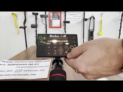
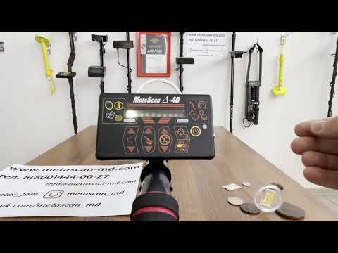
Брал для себя свободное время провести, профессионально поиском не занимаюсь, новичок. Выбрал Дельта 45 тк он на аккумуляторе и глубина хорошая. Сравнивал, смотрел видео-обзоры на Youtube и решил что это оптимальный выбор по цене и качеству. На днях нашел 3 серебряные монеты, сильно потерлись, примерно 18 век.
-
Дмитрий, Екатеринбург
Отзыв подтвержден. Связаться с Дмитрий
Самая глубокая находка 110 см, как он ее увидел, я не представляю. Была труба 50-ка, стенка 1 см, разрезанная. Дельта 45 ее увидел.
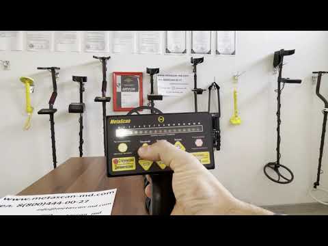
Взял для себя, время провести свободное. Я со знакомым езжу. У меня еще зарубежный прибор одной известной марки, он ее не увидел со стандартной катушкой.
Дельта 45 на стандартной увидел. Взял его для товарища, но теперь хожу с ним сам. Удобный по зарядке аккумулятор, не надо батарейки менять и покупать постоянно.
Положительное впечатление. Подбирал по глубине и цене. Считаю Дельта 45 превосходит по ним. -
Екатерина
Отзыв подтвержден. Связаться с Екатериной
Все проверили, все работает, все в норме. Брала сыну, 16 лет, выбирал сам, на OZON через приложение. В группе еще оставил отзыв, очень доволен.
-
Алексей, пгт. Красногорский
Отзыв подтвержден. Связаться с Алексеем
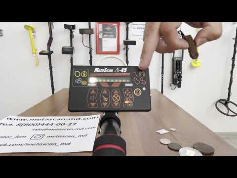
Взял как первый металлоискатель, простой для начала. Показал себя прекрасно, окупился за 3 выхода, пользуюсь около месяца. Сейчас на коп иду по выходным, раньше почти каждый день.
Находил башмаки тракторные, из крупных и так по мелочи.
Посоветовали друзья Дельта 45, сказали брать со встроенным аккумулятором, так удобнее. -
Азиз, Тамбов
Отзыв подтвержден. Связаться с Азизом
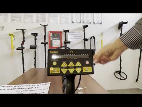
Первый металлоискатель, я начинающий. Взял для монет. Как то брал у друга металлоискатель для теста дорогой прибор, для себя взял Метаскан.
Читал отзывы, переживал, но все пришло, коробка и упаковка аккуратные, прибор обмотан пленкой, для защиты от повреждений внутри, качественно все собрано.
-
Елена Коровина, Саратов
Отзыв подтвержден. Связаться с Елена
Заказали Delta 45 на Ozon. Быстрая доставка. Комплектация полная. Металлоискатель лёгкий, удобный. Проверил в работе все 👌. Металл различает на цветной и чёрный . Мои находки меня радуют, буду пользоваться дальше. Приобретайте металлоискатели MetaSkan, не пожалеете! 😁

The
F-25/30/35/40 & 45
Combination Heaters
|
CONFORMS TO |
||
|
ANSI Z 21-10-3/UL 732 |
||
|
CERTIFIED TO |
||
|
90870 |
CSA B 140.12 |
|
|
CGA/CAN 1-4.3-M85 |
||
— Input from 100,000 to 199,000 Btu/hr —
* I N S T A L L A T I O N A N D M A I N T E N A N C E *
M A N U A L
Warranty Registration Card must be filled out by the customer and mailed within thirty (30) days of installa- NOTICE tion in order to gain warranty coverage.
When receiving Triangle Tube units, any claims for damage or shortage in shipment must be filed immediately against the transportation company by the consignee.
Leave all documentation received with appliance with owner for future reference.
WARNING If the information in this manual is not followed exactly, a fire or explosion may result causing property damage, personal injury or death.
For Your Safety
•Do not store or use gasoline or other flammable vapors and liquids in the vicinity of this or any other appliance.
•WHAT TO DO IF YOU SMELL GAS
—Do not try to light any appliance
—Do not touch any electrical switch; do not use any phone in your building.
—Immediately call your gas supplier from a neighbor’s phone. Follow the gas supplier’s instructions.
—If you cannot reach your gas supplier, call the fire department.
Installation and service must be performed by a qualified installer, service agency or the gas supplier
2004-7 Delta Elite Manual

Table of Contents
PRODUCT AND SAFETY INFORMATION
Definitions . . . . . . . . . . . . . . . . . . . . . . . . . . . . . . . . . . . . . . . . . . . . . . . . 1
Product Warnings . . . . . . . . . . . . . . . . . . . . . . . . . . . . . . . . . . . . . . . . . . . 2-3
Operating Restrictions . . . . . . . . . . . . . . . . . . . . . . . . . . . . . . . . . . . . . . . 4
Code Restrictions . . . . . . . . . . . . . . . . . . . . . . . . . . . . . . . . . . . . . . . . . . . 4
SECTION I — PRE-INSTALLATION ITEMS
Code Compliance . . . . . . . . . . . . . . . . . . . . . . . . . . . . . . . . . . . . . . . . . . . 5
Determining Product Location . . . . . . . . . . . . . . . . . . . . . . . . . . . . . . . . . 5
Boiler Replacement . . . . . . . . . . . . . . . . . . . . . . . . . . . . . . . . . . . . . . . . . 5
Recommended Clearances . . . . . . . . . . . . . . . . . . . . . . . . . . . . . . . . . . . . 5-6
Flooring and Foundation. . . . . . . . . . . . . . . . . . . . . . . . . . . . . . . . . . . . . . 6
Residential Garage Installations . . . . . . . . . . . . . . . . . . . . . . . . . . . . . . . . 6
SECTION II — COMBUSTION AIR AND VENTING
Providing Air for Combustion and Ventilation . . . . . . . . . . . . . . . . . . . . . 7-8 Removal of an Existing Boiler from a Common Vent . . . . . . . . . . . . . . . . 8
SECTION III — UNIT PREPARATION
Handling Instructions . . . . . . . . . . . . . . . . . . . . . . . . . . . . . . . . . . . . . . . . 9
Hydrostatic Pressure Test
Hydrostatic Test Preparation . . . . . . . . . . . . . . . . . . . . . . . . . . . . . 9
Hydrostatic Test Procedures . . . . . . . . . . . . . . . . . . . . . . . . . . . . . 9-10
Completion of Hydrostatic Test and Draining . . . . . . . . . . . . . . . . 10
SECTION IV — DOMESTIC PIPING
General Piping Requirements . . . . . . . . . . . . . . . . . . . . . . . . . . . . . . . . . . 11
Domestic Supply Pressure . . . . . . . . . . . . . . . . . . . . . . . . . . . . . . . . . . . . 11
Thermal Expansion. . . . . . . . . . . . . . . . . . . . . . . . . . . . . . . . . . . . . . . . . . 11
Water Hammer . . . . . . . . . . . . . . . . . . . . . . . . . . . . . . . . . . . . . . . . . . . . . 11
Temperature / Pressure Relief Valve . . . . . . . . . . . . . . . . . . . . . . . . . . . . . 11-12
Thermostatic Mixing Valve. . . . . . . . . . . . . . . . . . . . . . . . . . . . . . . . . . . . 12
i

Table of Contents
U-Tube Assembly. . . . . . . . . . . . . . . . . . . . . . . . . . . . . . . . . . . . . . . . . . . 12-13
Domestic Drain Valve. . . . . . . . . . . . . . . . . . . . . . . . . . . . . . . . . . . . . . . . 13
Multiple Units Installation . . . . . . . . . . . . . . . . . . . . . . . . . . . . . . . . . . . . 13
Storage Tank Application . . . . . . . . . . . . . . . . . . . . . . . . . . . . . . . . . . . . . 13
TR/Smart Series Application. . . . . . . . . . . . . . . . . . . . . . . . . . . . . . . . . . . 14
Domestic Piping Diagrams . . . . . . . . . . . . . . . . . . . . . . . . . . . . . . . . . . . . 14-16
SECTION V — PRIMARY PIPING
General Piping Requirements
Low Water Cut-off Device . . . . . . . . . . . . . . . . . . . . . . . . . . . . . . 17 Backflow Preventer. . . . . . . . . . . . . . . . . . . . . . . . . . . . . . . . . . . . 17 Primary System Piping Applications. . . . . . . . . . . . . . . . . . . . . . . . . . . . . 17
Expansion Tank and Makeup Water
Diaphragm (Bladder) Expansion Tank. . . . . . . . . . . . . . . . . . . . . . 17 Closed-Type (Standard) Expansion Tank . . . . . . . . . . . . . . . . . . . . 17 Circulator . . . . . . . . . . . . . . . . . . . . . . . . . . . . . . . . . . . . . . . . . . . . . . . . . 18 Closet (Zero Clearance) Applications . . . . . . . . . . . . . . . . . . . . . . . . . . . . 18 Sizing Primary Piping. . . . . . . . . . . . . . . . . . . . . . . . . . . . . . . . . . . . . . . . 18 System Piping — Zone Circulators . . . . . . . . . . . . . . . . . . . . . . . . . . . . . . . 18 System Piping — Zone Valves . . . . . . . . . . . . . . . . . . . . . . . . . . . . . . . . . . 18
System Piping — Radiant Heating with Mixing Valves. . . . . . . . . . . . . . . . 18-19 System Piping — Multiple Units Installation. . . . . . . . . . . . . . . . . . . . . . . . 19 Primary Piping Diagrams . . . . . . . . . . . . . . . . . . . . . . . . . . . . . . . . . . . . . 20-23
SECTION VI — VENTING
General Requirements. . . . . . . . . . . . . . . . . . . . . . . . . . . . . . . . . . . . . . . . 24
Oil Vent Piping. . . . . . . . . . . . . . . . . . . . . . . . . . . . . . . . . . . . . . . . . . . . . 24-25
Oil Vent -Direct Vent Applications . . . . . . . . . . . . . . . . . . . . . . . . . . . . . . 25
Gas Venting — General Requirements . . . . . . . . . . . . . . . . . . . . . . . . . . . . 26
Masonry and Metal Chimneys . . . . . . . . . . . . . . . . . . . . . . . . . . . . . . . . . 26
Type B Vent Systems . . . . . . . . . . . . . . . . . . . . . . . . . . . . . . . . . . . . . . . . 26
Vent Connectors . . . . . . . . . . . . . . . . . . . . . . . . . . . . . . . . . . . . . . . . . . . . 27
Common Vent System . . . . . . . . . . . . . . . . . . . . . . . . . . . . . . . . . . . . . . . 27
SECTION VII — FUEL PIPING
Gas Supply Piping Connection . . . . . . . . . . . . . . . . . . . . . . . . . . . . . . . . . 28 Pipe sizing -Natural Gas . . . . . . . . . . . . . . . . . . . . . . . . . . . . . . . . . . . . . . 29 Natural Gas Supply Pressure Requirements . . . . . . . . . . . . . . . . . . . . . . . 29
ii

Table of Contents
Pipe Sizing — Propane Gas . . . . . . . . . . . . . . . . . . . . . . . . . . . . . . . . . . . . 30
Propane Gas Supply Pressure Requirements . . . . . . . . . . . . . . . . . . . . . . . 30
General Oil Piping Guidelines . . . . . . . . . . . . . . . . . . . . . . . . . . . . . . . . . 30
SECTION VIII — INTERNAL WIRING
General Requirements. . . . . . . . . . . . . . . . . . . . . . . . . . . . . . . . . . . . . . . . 31
Internal Control Wiring Diagrams. . . . . . . . . . . . . . . . . . . . . . . . . . . . . . . 31-32
SECTION IX — EXTERNAL WIRING
Installation Compliance . . . . . . . . . . . . . . . . . . . . . . . . . . . . . . . . . . . . . . 33
Line Voltage Connections . . . . . . . . . . . . . . . . . . . . . . . . . . . . . . . . . . . . . 33
Thermostat Wiring . . . . . . . . . . . . . . . . . . . . . . . . . . . . . . . . . . . . . . . . . . 33
Outdoor Temperature Limit . . . . . . . . . . . . . . . . . . . . . . . . . . . . . . . . . . . 33
External Control Wiring Diagrams . . . . . . . . . . . . . . . . . . . . . . . . . . . . . . 34-36
SECTION X — START-UP PREPARATION
Check System and Domestic Water Chemistry
Water pH Level 6.0 to 8.0 . . . . . . . . . . . . . . . . . . . . . . . . . . . . . . . 37 Water Hardness Less Than 7 Grains . . . . . . . . . . . . . . . . . . . . . . . 37 Chloride Concentration Less Than 80mg/L . . . . . . . . . . . . . . . . . . 37 Chlorinated Water . . . . . . . . . . . . . . . . . . . . . . . . . . . . . . . . . . . . . 37 Flush Primary and Domestic System. . . . . . . . . . . . . . . . . . . . . . . . . . . . . 37
Check and Test Antifreeze . . . . . . . . . . . . . . . . . . . . . . . . . . . . . . . . . . . . 37 Use of Antifreeze in the Primary System . . . . . . . . . . . . . . . . . . . . . . . . . 38 Filling the Inner (Domestic) Tank and System . . . . . . . . . . . . . . . . . . . . . 38 Filling the Outer (Primary) Tank and System . . . . . . . . . . . . . . . . . . . . . . 38-39 Check Low Water Cut-off Device . . . . . . . . . . . . . . . . . . . . . . . . . . . . . . 39 Check for Gas Leaks . . . . . . . . . . . . . . . . . . . . . . . . . . . . . . . . . . . . . . . . 39 Check Thermostat Circuit . . . . . . . . . . . . . . . . . . . . . . . . . . . . . . . . . . . . . 39
SECTION XI — START-UP PROCEDURES
Final Checks Before Start-up . . . . . . . . . . . . . . . . . . . . . . . . . . . . . . . . . . 40
ELITE Start-up. . . . . . . . . . . . . . . . . . . . . . . . . . . . . . . . . . . . . . . . . . . . . 40-41
iii

Table of Contents
SECTION XII — TEMPERATURE LIMITS
Setting Primary Thermostat Limit. . . . . . . . . . . . . . . . . . . . . . . . . . . . . . . 42
Adjustment of Secondary Thermostat Limit . . . . . . . . . . . . . . . . . . . . . . . 42
Setting the Thermostatic Mixing Valve . . . . . . . . . . . . . . . . . . . . . . . . . . . 43
SECTION XIII — CHECK-OUT PROCEDURES
Check-out Procedures. . . . . . . . . . . . . . . . . . . . . . . . . . . . . . . . . . . . . . . . 44
SECTION XIV — INSTALLATION RECORD
Installation Record . . . . . . . . . . . . . . . . . . . . . . . . . . . . . . . . . . . . . . . . . . 45
SECTION XVII — REPLACEMENT PARTS
Replacement Parts . . . . . . . . . . . . . . . . . . . . . . . . . . . . . . . . . . . . . . . . . . 46-49
PRODUCT SPECIFICATIONS
Specifications . . . . . . . . . . . . . . . . . . . . . . . . . . . . . . . . . . . . . . . . . . . . . . 50-51
iv

Product & Safety Information
The following terms are used throughout this manual to bring attention to the presence of potential hazards or to important information concerning the product.
DANGER
NOTICE
Indicates the presence of a hazardous situation which, if ignored, will result in death, serious injury or substantial property damage.
Indicates special instructions on installation, operation or maintenance, which are important to equipment but not related to personal injury hazards.
WARNING
Indicates a potentially hazardous situation which, if ignored, can result in death, serious injury or substantial property damage.
CAUTION
Indicates a potentially hazardous situation which, if ignored, may result in minor injury or property damage.
BEST PRACTICES
Indicates recommendations made by Triangle Tube for the installers which will help to ensure optimum operation and longevity of the equipment
NOTICE
Triangle Tube reserves the right to modify the technical specifications and components of its products without prior notice.
1
Product & Safety Information
WARNING
Bacteria can develop in the domestic water system if certain minimum water temperatures are not maintained.
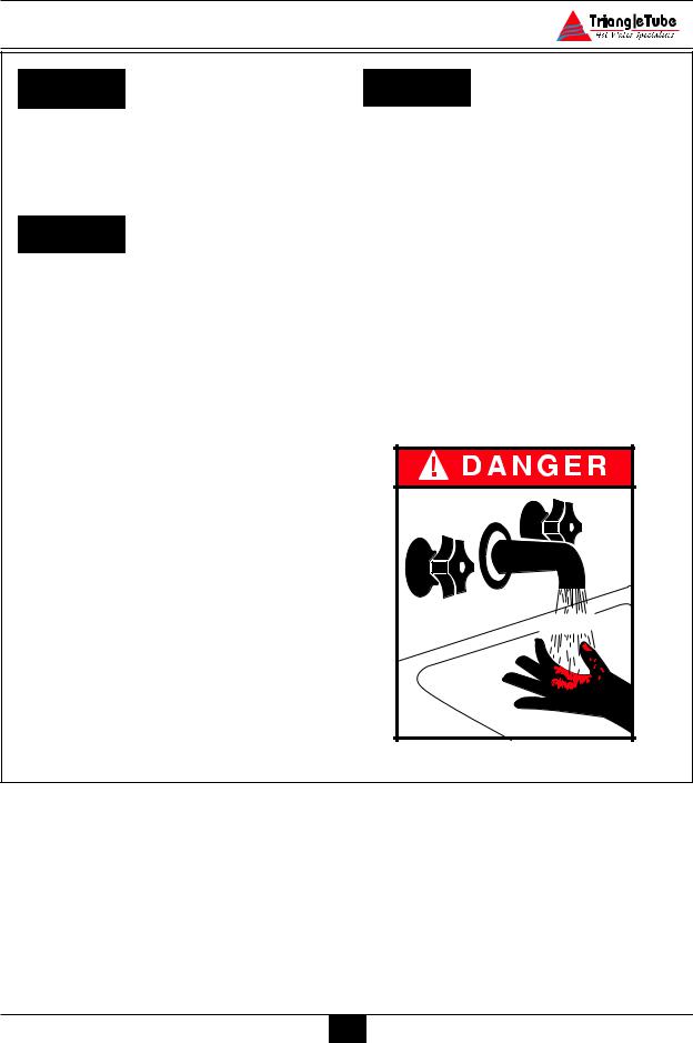
DANGER
Water temperature over 125ºF can cause severe burns instantly or death from scalds.
•Children, disabled and elderly are at highest risk of being scalded.
—Never leave them unattended in or near shower, bathtub or sink.
—Never allow small children to use a hot water faucet or draw their own bath.
•If any one using hot water in the building fits this description or codes require specific water temperatures at hot water faucet, we recommend:
a)ensure the factory installed thermostatic mixing valve is working properly.
b)to set the thermostatic mixing valve for the lowest temperature which satisfies your hot water need.
CAUTION
.
Protection must be taken against excessive temperature and pressure!
TO PROTECT AGAINST EXCESSIVE TEMPERATURE AND PRESSURE
•Check if the Temperature and Pressure (T&P) relief valve is in the location provided. (Domestic Water)
•Check if the 30 psi relief valve supplied is in the location provided. (Primary water)
•To avoid injury, install the relief devices to comply with local code requirements.
2

Product & Safety Information
Do not use this appliance if any part has been under water. Immediately call a qualified service technician to inspect the appliance and to replace any part of the control system which has been under water.
DANGER
WHAT TO DO IF YOU SMELL GAS — Do not try to light any appliance
Should overheating occur or the gas supply fails to shut off, turn OFF the manual gas control valve external to the appliance.
CAUTION
To prevent damage to inner tank, installer must:
—Do not touch any electrical switch; do not use any phone in your building.
—Immediately call your gas supplier from a neighbor’s phone. Follow the gas supplier’s instructions.
—If you cannot reach your gas supplier, call the fire department.
Installation and service must be performed by a qualified installer, service agency or the gas supplier.
•Fill inner tank prior to outer tank during start-up.
•Relieve primary system pressure below 15 psig prior to draining inner tank.
|
WARNING |
NOTICE |
|||||
|
Qualified Installer: |
Please reference the unit’s model num- |
|||||
|
Prior to installing this product |
read all |
ber and the serial number from the rat- |
||||
|
ing label when inquiring about service or |
||||||
|
instructions included |
in this |
manual. |
|
Perform all installation steps required in this |
troubleshooting. |
||||||
|
manual in the proper order given. Failure to |
|||||||
|
adhere to the guidelines within this manual |
NOTICE |
||||||
|
can result in severe personal injury, death or |
|||||||
|
substantial property damage. |
Triangle Tube accepts no liability for any |
||||||
|
damage resulting from incorrect instal- |
|||||||
|
Homeowner: |
lation or from the use of components or |
||||||
|
fittings not specified by Triangle Tube. |
|||||||
|
-This product should be maintained / ser- |
|||||||
|
viced and inspected annually by a qual- |
|||||||
|
ified service technician. |
|||||||
|
— This manual is intended for use by a |
|||||||
|
qualified Installer/Service Technician. |
|||||||
|
3 |
|||||||

Product & Safety Information
OPERATING RESTRICTIONS
•Maximum working pressure for inner (domestic water) tank is 150 psig.
•Maximum working pressure for outer (primary water) tank is 45 psig.
•Inner tank has factory installed Temperature & Pressure Relief Valve with an AGA rating of 100,000 Btu/hr for PG-25 and 200,000 Btu/hr for PG30/35/40/45.
•Outer tank has a factory installed 30 psig relief valve rated at 535,000 Btu/hr
•Electrical rating:120 V, 60 Hz, less than 12 amperes
•pH & chloride limits for the ELITE are:
—Chloride, less than 80 mg/l.
—pH, 6.0 — 8.0.
NOTICE
Any water conditioning system must be installed and maintained in accordance with manufacturer’s specifications.
•180º Maximum operating temperature — primary side.
•120º Maximum outlet/mixed temperature — domestic side.
CODE RESTRICTIONS
Single wall heat exchanger in the ELITE complies with National Standard Plumbing Code, provided that:
—Outer tank water (including additives) is practically non-toxic, having toxicity rating or Class of 1, as listed in Clinical Toxicology of Commercial Products,
—Outer tank pressure is limited to maximum 30 psig by approved relief valve.
Single wall heat exchangers are permitted under the Uniform Plumbing code — Paragraph L3.2. if they satisfy all of the following requirements.
1.The heat transfer medium is potable water or contains only substances which are recognized as safe by the U.S. Food and Drug Administration.
2.The pressure of the heat transfer medium is maintained less than the normal minimum operating pressure of the potable water system
3.The equipment is permanently labeled to indicate that only additives recognized as safe by the FDAshall be used in the heat transfer medium.
Or, per Uniform Plumbing Code paragraph L3.3 as follows:
Other heat exchanger designs may be permitted where approved by the Administrative Authority.
4

Pre-Installation Items
SECTION I — Pre-Installation Items
Code Compliance
This product must be installed in accordance to the following:
•All applicable local, state, national and provincial codes, ordinances, regulations and laws.
•The National Fuel Gas Code NFPA54/ ANSI Z332.1 — Latest edition.
•Installation of Oil Burning Equipment NFPA 31 — Latest Edition
•National Electric Code ANSI/NFPA 70.
•For installations in Canada -“Installation Code for Gas Burning Equipment” CGA/B149.
•For installations in Canada — Installation code for Oil Burning Equipment — CSA/B139.
Determining Product Location
Before locating the ELITE check for convenient locations to:
—Domestic water supply piping
—Heating system piping
—Venting
—Gas or oil supply piping
—Electrical service
Ensure the area chosen for the installation of the ELITE is free of any combustible materials, gasoline and other flammable liquids.
WARNING
Failure to remove or maintain the area free of combustible materials, gasoline and other flammable liquids or vapors can result in severe personal injury, death or substantial property damage.
Ensure the ELITE and its controls are protected from dripping or spraying water during normal operation or service.
The ELITE should be installed in a location so that any water leaking from the tank or piping connections or relief valves will not cause damage to the area surrounding the unit or any lower floors in the structure.
—When such a location is unavoidable a suitable drain pan with adequate drainage should be placed under the unit. The drain pan must not restrict the flow of combustion air to the unit.
Boiler Replacement
If the ELITE is replacing an existing boiler / hot water heater system, the following items should be checked and corrected prior to installation:
•Primary and domestic piping leaks and corrosion.
•Improper location and sizing of the expansion tank on the primary heating loop.
•Improper sizing of the thermal expansion tank (if used) on the domestic supply line.
•Vent condition and sizing.
Recommended Clearances
The ELITE is approved for zero clearance to combustibles, excluding the vent hood and vent piping.
Vent hood and vent piping — 6 inches from combustible materials when using type “L” double wall vent.
Vent Piping — 18 inches from combustible materials when using single wall vent.
Primary and domestic hot water piping — 1 inch from combustible material.
5
![]()
Pre-Installation Items
BEST PRACTICES
To provide serviceability to the unit it is recommended that the following clearances be maintained:
Top and vent hood area — 36 inches.
Front and burner area — 24 inches.
Rear and primary piping areas — 12 inches.
WARNING
When installing the ELITE in a confined space, sufficient air must be provided for proper combustion and venting and to allow under normal operating condition, proper air flow around the product to maintain ambient temperatures within safe limits to comply with the National Fuel Gas Code NFPA 54 — latest edition.
Flooring and Foundation
The ELITE is approved for installation on combustible floors, but never on carpeting.
WARNING
Do not install the ELITE on carpeting even with a metal or wood foundation base. Fire can result causing severe personal injury, death or substantial property damage.
Installer should provide a solid brick or concrete foundation pad, at least 2 inches above the floor level if:
—There is a potential for the floor to become flooded. The height of the foundation should be such to sufficiently elevate the unit.
—The floor is dirt, sand, gravel or other loose material.
—The flooring is severely uneven or sloped.
The minimum foundation size required is 24 inches x 23 inches.
Residential Garage Installations
When installing the ELITE in a residential garage the following special precautions per NFPA 54/ANSI Z223.1 must be taken:
—Mount the unit with a minimum 18 inches above the floor level of the garage. Ensure the burner and ignition devices / controls are no less than 18 inches above the floor level.
—Locate or protect the unit in a matter so it cannot be damaged by a moving vehicle.
6

Combustion Air and Venting
SECTION II — Providing Air for Combustion and Ventilation
WARNING
The installer must provide adequate combustion and ventilation to the area in which the ELITE is installed. Providing adequate air ensures proper combustion and reduces the potential risk of severe personal injury or death from carbon monoxide emissions if a flue gas leakage occurred.
WARNING
The installer should not install an exhaust fan in the room with the ELITE. The exhaust fan could affect the combustion of the burner or cause potential flue gas leakage resulting in severe personal injury or death.
NOTICE
The installer should take the condition and age of the building when determining air for ventilation. Older building (buildings with single pane windows and minimal weather-stripping around doors and windows) tend to have adequate natural infiltration and ventilation without providing dedicated air openings. Newer buildings (buildings with double pane windows and weather-stripped doors and windows) are unlikely to have natural infiltration and ventilation, thus must be provided with dedicated air openings.
The installer must follow the requirements of state, provincial or local codes when sizing and locating adequate air openings for combustion and ventilation.
In absence of the codes the installer may opt to use the following guidelines when the ELITE is installed in a confined room as defined by NFPA 31 as a room with less than 7200 cubic feet per 1 GPH of input of all appliances located in the area (7200 cubic feet is define as a room with 8 foot ceiling and 33.5 ft x 33.5 ft in dimension):
Two Permanent Openings — One opening must commence within 12 inches of the ceiling and the other opening within 12 inches of the floor. The opening must have a minimum height or length dimension of 3 inches, the actual dimensions are based on:
Using Inside Air — Each opening must be connected freely to the areas having adequate infiltration from the outside. Each opening should be at least 140 sq. inches per 1 GPH of input (1 sq. inch per 1000 BTU input). This input should include all appliances (gas and/or oil) plus any appliances that may draw air from the room such as clothes dryers.
Using Outside Air — Each opening should be connected directly or by ducts to the outdoors or to a crawl space or attic area that is freely connected with the outdoors. The openings should be sized as follows:
Through outside wall or vertical ducts —
The openings should be a minimum 35 sq inches per 1 GPH input (1 sq. inch per 4000 BTU input) of all appliances (gas and/or oil) plus any appliances that may draw air from the room such as clothes dryers.
Through horizontal ducts — The openings should be a minimum 70 sq. inches per 1 GPH input (1 sq. inch per 2000 BTU input) of all appliances (gas and/or oil) plus any appliances that may draw air from the room such as clothes dryers.
Where ducts are used, the size of the duct should equal the free area of the opening in which the duct is connected to.
7

Combustion Air and Venting
The installer should compensate for any louvers, grilles or screens when determining the free air of the opening. The installer should refer the louver or grille manufacturer’s instruction for determining free area. In absence of the manufacturer’s instructions the installer should use the following as a guideline:
—Wood louvers will provide 20 to 25% free area
—Metal louvers or grilles will provide 60 to 75% free air
Installers should lock louvers in the open position or provide an interlock system to prove the louvers are in the open position prior to operation of the ELITE.
Removal of an Existing Boiler from a Common Vent System
BEST PRACTICES
For installations in which the ELITE is replacing an existing boiler / hot water heater system, which was connected to a common vent system with other appliances, the following steps shall be conducted with each remaining appliance connected to the common venting system:
1.Any unused openings in the common venting system must be sealed.
2.A visual inspection of the venting system must be conducted for proper sizing and horizontal pitch. The inspection should ensure no blockage or restriction is within the vent system, and there is no leakage, corrosion or other items, which could cause an unsafe condition.
3.To adequately test the venting system, close all exterior doors and windows and all doors between the area containing the remaining appliances connected to the common vent system and other areas of the building. Turn on any clothes dryers and any other gas appli-
ance not connected to the common vent system. Turn on all exhaust fans, i.e. range hoods and bathroom exhaust fans, preferably at maximum speed. Close any fireplace dampers.
4.Place in operation the first appliance being inspected that is connected to the common vent system. The remaining appliances should not be in operation. Follow the appliance’s lighting instructions and adjust the thermostat to allow the appliance to operate continuously.
5.Test for spillage at the draft hood relief opening after 5 minutes of main burner operation. Spillage can be detected using the flame of a match or candle or with smoke from a cigarette.
6.Once it has been determined that each remaining appliance connected to the common vent system is properly vented, return doors, windows, exhaust fans, fireplace dampers and any operating gas appliance to their previous condition.
Should any improper operation of the common venting system be detected in the outlined test, the condition should be corrected so the vent system conforms with the National Fuel Gas Code, NFPA 54/ ANSI Z223.1 — latest edition. Canadian installations must conform with B149.1 or 149.2 Installation Code.
8

Unit Preparation
SECTION III — Unit Preparation
Handling Instructions
The ELITE is generally easier to handle and maneuver once removed from the shipping carton and pallet.
To remove the shipping carton and pallet:
a.Remove the shipping straps and open the top of the shipping carton to remove the wood shipment insert.
b.Lift the shipping carton over the unit to remove. If ceiling height is limited the carton maybe cut open using care not to damage the exterior jacket of the unit.
c.Discard all packing materials.
Hydrostatic Pressure Test
BEST PRACTICES
Prior to permanently connecting water, oil/gas supply or electrical supply, perform a pressure hydrostatic test of the outer tank to ensure all piping connections were not damaged during shipment.
Hydrostatic Test Preparation
1.Mount the circulator on the supply pipe as shown in Fig. 7 page 20.
2.Temporarily plug the primary return connections as shown in Fig. 7 page 20 using a 1” NPT pipe plug. Use pipe dope sparingly to allow removal of the plugs upon completion of the test.
3.On the outlet flange of the circulator pipe install a 1” NPT nipple and shut-off valve. Use pipe dope sparingly to allow removal of the fittings upon completion of the test.
NOTICE
To avoid getting water onto the unit and/or surrounding area additional piping from the shut-off to a catch bucket or drain may be required.
4.Connect a hose to the primary circuit drain valve located per Fig. 28 page 50, Item 2 and connect the other end to a fresh water supply. Ensure the hose can be used as a drain hose upon completion of the test.
Hydrostatic Test Procedures
1.Open the shut-off valve installed on the outlet flange of the circulator.
2.Open the fresh water supply valve and then open slowly the primary circuit drain valve to fill the outer tank with water.
3.When the water within the outer tank reaches the shut-off on the primary supply, close the primary circuit drain valve.
4.Close the shut-off valve, on the top of the circulator.
5.Slowly reopen the primary circuit drain valve until the test pressure on the temperature / pressure gauge reaches 10 psig maximum. Close the primary circuit drain valve.
CAUTION
To prevent damage to the inner tank the test pressure must not exceed 10 psig.
6.Allow the test pressure to remain for 10 minutes.
WARNING
Do not leave the unit unattended while pressurized. A cold water fill could expand and cause excessive pressure, resulting in severe personal injury, death or substantial property damage.
9

Unit Preparation
7.Ensure constant gauge pressure has been Completion of Hydrostatic Test and Draining maintained throughout the 10 minute test. 1. Disconnect the fill hose from the freshCheck for leaks at all fitting joints. Repair
if found.
WARNING
Leaks must be repaired immediately when detected. Failure to repair leaks can damage the unit, resulting in substantial property damage.
8.Check continuity using a voltmeter across the terminals of the LWCO device. The contacts on the LWCO should be closed. See item 6 in Fig. 24 page 47 for location of the LWCO.
water source and direct the hose to a suitable place of drainage.
2.Open the primary drain valve and completely drain the unit. To aid in draining, open the shut-off valve on the primary supply.
3.Remove the hose from the primary drain valve when draining is complete.
4.Remove the plugs, nipple, shut-off valve and any other piping unless they will remain for use in the system piping.
10

Domestic Piping
SECTION IV — Domestic Piping
General Piping Requirements
•All plumbing must meet or exceed all local, state and national plumbing codes.
•Use pipe dope or tape suitable for potable water.
•Use isolation valves to isolate system components.
•Install unions for easy removal of the ELITE from the system piping.
Domestic Supply Pressure
For applications in which the domestic supply pressure exceeds 70 psig it is recommended to install a pressure reducing valve on the cold water supply.
Maintaining the cold water supply at or below 70 psig will prevent normal thermal expansion from repeatedly forcing the T&P relief valve open.
Thermal Expansion
If the cold water supply contains a backflow preventer, check valve and / or a pressure reducing valve, the installer must install a domestic thermal expansion tank on the cold water supply. (See Fig. 2 page 14)
Installing a thermal expansion tank will prevent normal thermal expansion from repeatedly forcing the T&P relief valve open.
When installing a thermal expansion tank ensure the charge pressure of the tank is equal to the cold water supply pressure at the point of installation. Consult the thermal expansion tank manufacturer’s instructions for further information on installation and sizing.
CAUTION
The Temperature / Pressure relief valve is not intended for constant duty, such as relief of pressure due to normal thermal expansion.
Water Hammer
Water hammer is the effect of sudden pressure changes occurring in the domestic piping. These pressure changes are typically the result of “fast acting” positive shut-off valves closing. These types of valves can be typically found on dishwashers and clothes washers.
The effects of water hammering can cause damage to system components and tank welds on the unit.
Installation of hammer arresters is recommended at these types of appliances, which incorporate “fast-acting” positive shut-off valves. Consult the manufacturer of water hammer arresters for recommendation on sizing and installation requirements.
Temperature / Pressure Relief Valve
The ELITE has a factory installed Temperature / Pressure Relief valve. Ensure the rating of the T&P relief valve is correctly sized as follows per AGA:
|
Model |
AGA Rating |
|
F-25 |
100,000 Btu/hr |
|
F-30 |
200,000 Btu/hr |
|
F-35 |
200,000 Btu/hr |
|
F-40 |
200,000 Btu/hr |
|
F-45 |
200,000 Btu/hr |
11

Domestic Piping
The installer must install discharge piping onto the T&P relief valve. The discharge piping must be:
•Made of material serviceable for temperatures of 250ºF or greater.
•Directed so that any hot water discharge flows away from all persons.
•Directed to a suitable place of drainage.
•Installed as to allow complete draining of the T&P relief valve and the discharge piping.
•Terminated with a plain end, not with threads.
WARNING
DO NOT install any valves between the T&P relief valve and the discharge piping. DO NOT plug the T&P relief valve or the discharge piping. Improper placement and piping of the T&P relief valve can cause severe personal injury, death or substantial property damage.
Thermostatic Mixing Valve
The ELITE contains a factory installed thermostatic mixing valve with built-in check valve.
The operating range of the thermostatic mixing is 90ºF to 120ºF.
CAUTION
Failure to properly direct the discharge piping of the T&P relief valve may result in flooding of the area adjacent to the unit and or lower floors in the structure causing substantial property damage.
The installer must not install the T&P relief valve discharge piping in a manner that is:
•Excessively long: Using more than 2 elbows and/or 15 feet of discharge piping can reduce the discharge capacity.
•Terminated directly into a drain: The discharge piping must terminate within 6 inches of the drain. Check with local plumbing codes for termination guidelines.
•The discharge piping is plugged, reduced in size or restricted in any manner.
•The discharge piping is subject to freezing.
For applications with a domestic recirculation loop, the recirculation pump should be controlled by an aquastat. The maximum recommended setting of the aquastat is 10ºF lower than the thermostatic mixing valve setting.
DANGER
For proper operation of the thermostatic mixing valve and to prevent potential scalding hazards, the recirculation loop should be controlled by an aquastat. DO NOT use continuous recirculation.
U-Tube Assembly
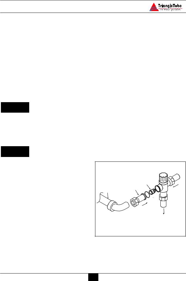
The ELITE is supplied with a U-Tube Assembly that directs cold water to the thermostatic mixing valve.
To install the U-Tube Assembly the installer must:
1.Disconnect the cold inlet adapter/union from the thermostatic mixing valve.
2.Using needle-nose pliers remove the plastic check valve assembly from the adapter.
12
Domestic Piping
3.Solder the U-Tube Assembly onto the adapter. (See Fig. 1)
4.Once the adapter has sufficiently cooled, re-insert the check valve assembly making sure of orientation and reconnect onto the mixing valve.
If the installation of the ELITE requires domestic hot water for a commercial dishwasher, the installer may insert a tee connection between the unit and the mixing valve to provide 140ºF domestic hot water. The installer must reference local plumbing codes to ensure if this type of application is permissible.
DANGER
The thermostatic mixing valve MUST be installed and utilized on the ELITE. Removal of the thermostatic mixing valve will result in severe personal injury or death.
CAUTION
The installer should remove the thermostatic mixing valve from the units and install a single thermostatic mixing valve at the outlet of the hot water manifold. The thermostatic mixing valve should be sized according to the required flow rate and pressure drop. Refer to the thermostat mixing valve manufacturer specification and installation instructions for more details.
Reference Fig. 4, page 15 for piping diagram.
Storage Tank Application
For applications requiring large volumes of domestic hot water in a relative short period, the installer may include a storage type tank (see Fig. 5 page 16) in the domestic piping. The installer must:
1.Relocate the thermostatic mixing valve from the ELITE to the outlet of the storage tank.
2.Provide recirculation from the storage tank back to the ELITE using a bronze type circulator. Maximum recommended flow rate is 5 to 10 gpm.
The manual valve on the U-Tube assembly must remain in the full open position for proper operation of the thermostatic mixing valve.
Domestic Drain Valve
—The installer must install a drain valve and drain leg as shown in Fig. 2 page 14 or Fig. 3 page 15.
—The drain valve should be positioned close to the floor to aid in the siphon action required to drain the inner tank.
Multiple Units Installation
For applications using multiple units the domestic piping should be piped using a balanced manifold arrangement.
|
Check Valve |
|
|
Adapter |
ot |
|
H |
|
|
U-Tube Assembly |
|
|
Cold |
|
|
Mixed |
|
|
Fig. 1: Mixing Valve Assembly |
13
 Loading…
Краткое содержание страницы № 1
The
F-25/30/35/40 & 45
Combination Heaters
CONFORMS TO
ANSI Z 21-10-3/UL 732
CERTIFIED TO
CSA B 140.12
90870
CGA/CAN 1-4.3-M85
— Input from 100,000 to 199,000 Btu/hr —
* I N S T A L L A T I O N A N D M A I N T E N A N C E *
* I N S T A L L A T I O N A N D M A I N T E N A N C E *
M A N U A L
M A N U A L
Warranty Registration Card must be filled out by the customer and mailed within thirty (30) days of installa-
NOTICE tion in order to gain warranty coverage.
When receiving Tri
Краткое содержание страницы № 2
Table of Contents PRODUCT AND SAFETY INFORMATION Definitions . . . . . . . . . . . . . . . . . . . . . . . . . . . . . . . . . . . . . . . . . . . . . . . . 1 Product Warnings . . . . . . . . . . . . . . . . . . . . . . . . . . . . . . . . . . . . . . . . . . . 2-3 Operating Restrictions . . . . . . . . . . . . . . . . . . . . . . . . . . . . . . . . . . . . . . . 4 Code Restrictions . . . . . . . . . . . . . . . . . . . . . . . . . . . . . . . . . . . . . . . . . . . 4 SECTION I — PRE-INSTALLAT
Краткое содержание страницы № 3
Table of Contents U-Tube Assembly. . . . . . . . . . . . . . . . . . . . . . . . . . . . . . . . . . . . . . . . . . . 12-13 Domestic Drain Valve. . . . . . . . . . . . . . . . . . . . . . . . . . . . . . . . . . . . . . . . 13 Multiple Units Installation . . . . . . . . . . . . . . . . . . . . . . . . . . . . . . . . . . . . 13 Storage Tank Application . . . . . . . . . . . . . . . . . . . . . . . . . . . . . . . . . . . . . 13 TR/Smart Series Application. . . . . . . . . . . . . . . . . . . .
Краткое содержание страницы № 4
Table of Contents Pipe Sizing — Propane Gas . . . . . . . . . . . . . . . . . . . . . . . . . . . . . . . . . . . . 30 Propane Gas Supply Pressure Requirements . . . . . . . . . . . . . . . . . . . . . . . 30 General Oil Piping Guidelines . . . . . . . . . . . . . . . . . . . . . . . . . . . . . . . . . 30 SECTION VIII — INTERNAL WIRING General Requirements. . . . . . . . . . . . . . . . . . . . . . . . . . . . . . . . . . . . . . . . 31 Internal Control Wiring Diagrams. . . . . . . . . . . . .
Краткое содержание страницы № 5
Table of Contents SECTION XII — TEMPERATURE LIMITS Setting Primary Thermostat Limit. . . . . . . . . . . . . . . . . . . . . . . . . . . . . . . 42 Adjustment of Secondary Thermostat Limit . . . . . . . . . . . . . . . . . . . . . . . 42 Setting the Thermostatic Mixing Valve . . . . . . . . . . . . . . . . . . . . . . . . . . . 43 SECTION XIII — CHECK-OUT PROCEDURES Check-out Procedures. . . . . . . . . . . . . . . . . . . . . . . . . . . . . . . . . . . . . . . . 44 SECTION XIV — INSTALLATION R
Краткое содержание страницы № 6
Product & Safety Information The following terms are used throughout this manual to bring attention to the presence of potential hazards or to important information concerning the product. DANGER NOTICE Indicates the presence of a hazardous Indicates special instructions on instal- situation which, if ignored, will result lation, operation or maintenance, in death, serious injury or substantial which are important to equipment but property damage. not related to personal injury hazards. WARNING
Краткое содержание страницы № 7
Product & Safety Information CAUTION WARNING . Protection must be taken against excessive Bacteria can develop in the domestic temperature and pressure! water system if certain minimum water temperatures are not maintained. TO PROTECT AGAINST EXCESSIVE TEMPERATURE AND PRESSURE DANGER • Check if the Temperature and Pressure (T&P) relief valve is in the Water temperature over 125ºF can cause location provided. (Domestic Water) severe burns instantly or death from • Check if the 30 psi relief valv
Краткое содержание страницы № 8
Product & Safety Information DANGER WARNING Do not use this appliance if any part Should overheating occur or the gas has been under water. Immediately call supply fails to shut off, turn OFF the a qualified service technician to inspect manual gas control valve external to the appliance and to replace any part of the appliance. the control system which has been under water. CAUTION DANGER WHAT TO DO IF YOU SMELL GAS To prevent damage to inner tank, — Do not try to light any appliance installer
Краткое содержание страницы № 9
Product & Safety Information OPERATING RESTRICTIONS CODE RESTRICTIONS • Maximum working pressure for inner Single wall heat exchanger in the ELITE (domestic water) tank is 150 psig. complies with National Standard Plumbing Code, provided that: • Maximum working pressure for outer — Outer tank water (including additives) (primary water) tank is 45 psig. is practically non-toxic, having toxicity • Inner tank has factory installed rating or Class of 1, as listed in Clinical Temperature & Pressure R
Краткое содержание страницы № 10
Pre-Installation Items Ensure the ELITE and its controls are protect- SECTION I — Pre-Installation Items ed from dripping or spraying water during nor- mal operation or service. Code Compliance This product must be installed in accor- The ELITE should be installed in a location so dance to the following: that any water leaking from the tank or piping connections or relief valves will not cause • All applicable local, state, national and damage to the area surrounding the unit or any provincial c
Краткое содержание страницы № 11
Pre-Installation Items BEST PRACTICES Installer should provide a solid brick or con- crete foundation pad, at least 2 inches above To provide serviceability to the unit it is the floor level if: recommended that the following clear- ances be maintained: — There is a potential for the floor to become flooded. The height of the Top and vent hood area — 36 inches. foundation should be such to sufficient- ly elevate the unit. Front and burner area — 24 inches. — The floor is dirt, sand, gravel or o
Краткое содержание страницы № 12
Combustion Air and Venting In absence of the codes the installer may opt to SECTION II — Providing Air for use the following guidelines when the ELITE Combustion and Ventilation is installed in a confined room as defined by NFPA 31 as a room with less than 7200 cubic feet per 1 GPH of input of all appliances locat- WARNING ed in the area (7200 cubic feet is define as a The installer must provide adequate room with 8 foot ceiling and 33.5 ft x 33.5 ft in combustion and ventilation to the area in
Краткое содержание страницы № 13
Combustion Air and Venting The installer should compensate for any lou- ance not connected to the common vent vers, grilles or screens when determining the system. Turn on all exhaust fans, i.e. free air of the opening. The installer should range hoods and bathroom exhaust refer the louver or grille manufacturer’s fans, preferably at maximum speed. instruction for determining free area. In Close any fireplace dampers. absence of the manufacturer’s instructions the 4. Place in operation the fi
Краткое содержание страницы № 14
Unit Preparation SECTION III — Unit Preparation NOTICE Handling Instructions To avoid getting water onto the unit The ELITE is generally easier to handle and and/or surrounding area additional pip- maneuver once removed from the shipping car- ing from the shut-off to a catch bucket or ton and pallet. drain may be required. 4. Connect a hose to the primary circuit drain To remove the shipping carton and pallet: valve located per Fig. 28 page 50, Item 2 a. Remove the shipping straps and open and
Краткое содержание страницы № 15
Unit Preparation 7. Ensure constant gauge pressure has been Completion of Hydrostatic Test and Draining maintained throughout the 10 minute test. 1. Disconnect the fill hose from the fresh Check for leaks at all fitting joints. Repair water source and direct the hose to a suit- if found. able place of drainage. 2. Open the primary drain valve and complete- ly drain the unit. To aid in draining, open the WARNING shut-off valve on the primary supply. Leaks must be repaired immediately 3. Remove
Краткое содержание страницы № 16
Domestic Piping SECTION IV — Domestic Piping CAUTION General Piping Requirements The Temperature / Pressure relief valve is not intended for constant duty, such as • All plumbing must meet or exceed all relief of pressure due to normal thermal local, state and national plumbing codes. expansion. • Use pipe dope or tape suitable for potable water. Water Hammer • Use isolation valves to isolate system components. Water hammer is the effect of sudden pres- sure changes occurring in the domestic pip
Краткое содержание страницы № 17
Domestic Piping The installer must install discharge piping WARNING onto the T&P relief valve. The discharge piping must be: DO NOT install any valves between the T&P relief valve and the discharge pip- • Made of material serviceable for tem- ing. DO NOT plug the T&P relief valve peratures of 250ºF or greater. or the discharge piping. Improper place- • Directed so that any hot water dis- ment and piping of the T&P relief valve charge flows away from all persons. can cause severe personal inju
Краткое содержание страницы № 18
Domestic Piping 3. Solder the U-Tube Assembly onto the The installer should remove the thermostatic adapter. (See Fig. 1) mixing valve from the units and install a single thermostatic mixing valve at the outlet of the 4. Once the adapter has sufficiently hot water manifold. The thermostatic mixing cooled, re-insert the check valve assem- valve should be sized according to the required bly making sure of orientation and flow rate and pressure drop. Refer to the ther- reconnect onto the mixing v
Краткое содержание страницы № 19
Domestic Piping TR/SMART Series Application The primary piping to the TR/SMART Series tank must comply with the piping methods For applications requiring large volumes of details in SECTION V — Primary Piping or with domestic hot water over an extended period, other recognized piping methods. the installer may include a Triangle Tube TR/SMART Indirect Water Heater in conjunc- Additional information regarding domestic and tion with the ELITE. (See Fig. 6 page 16) primary piping can be found in t
Краткое содержание страницы № 20
Domestic Piping Optional recirculation line 3 2 7 3 1 To dishwasher if 12″ Heat trap permitted by codes Cold water 3 9 4 3 inlet 6 Note: All shut off valves 8 shown in this figure must be closed when siphon draining Fig. 3: ELITE With Recirculation the ELITE Optional recirculation line 7 2 3 1 12″ Heat trap Cold water 3 4 inlet 3 9 6 8 Fig. 4: Multiple Units Installation With Recirculation 1. Mixing valve with check valve 6. Thermal expansion tank 2. Flow check valve 7. Circulator (con
Отзывы
— Виталий Мирон
Плюсы: В целом устраивает
Минусы: Не внушает крепление крышки аккумуляторов
Коммент: Приспособиться надо, там посмотрим
— LaGrande
Плюсы: Хорошо ловит сигнал. Есть регулировки. Легкий, встроенная батарея. Можно опускать в воду.
Минусы: Иногда зависает и орёт как безумный, если бы не эта хрень — я бы восхвалял этот металлоискатель!!!
Крепление катушки — гомно полное. Легко и внезапно разбалтывается и очень бесит, ходить до машины за отвёрткой. Т.к рукой протянуть нереально и толстой отверткой тоже. А если затягиваешь сильно, начинают срываться грани пластика.
По сравнению с конкурентами — выглядит как нищий, тоненький пластик и катушка, по началу над ним смеялись, но только по началу..
Коммент: Я новичок, НО я сравнивал с Xterra 705, Garret Ace 250. Первый день ходил с друзьями, на «второй» один — с их металлоискателями и посветил тесту металлоискателей и изучению их сигналов. Ловил сигнал одним, потом уносил за 2 метра и брал для теста другой. Сравнивал силу сигнала, металл который они показывают, а так же глубину, копал и доставал.
Мой вывод таков, только копать и смотреть: любой металлоискатель до 150 тыс — никогда не покажет на 100% точно сорт металла и изделие под ногами. На золото они тоже реагирую по разному, можно положить кольцо на траву и сигнал будет еле-еле и далеко не на всех настройках. А на 15 см глубины в мёрзлой почве Xterra 705 и Metascan45 увидят медный старинный гвоздь и будут орать как резанные, что там золото! Ace250 вообще промолчала в том месте, даже если всё поставить на максимум, только когда копнул — дала очень слабый сигнал.
MetaScan Delta 45 — проявил себя очень достойно по уровню сигналов, чернуху копать — его стихия, даже не сомневайтесь. В грунте ручья — Xterra 705 еле уловила сигнал железяки размером с кулак на глубине 20-25 см и массой грамм 100-200, MetaScan45 чётко сигнализировал, что здесь что то есть цветное, благодаря центровке достал с 2-3 лопат.
Чем лучше Xterra и Аска 250? 1. Качество сборки, 2. запас прочности, 3. удобность управления и регулировок.
Чем лучше Metoscan45? 1. Цена. 2. Легкий. Намного лучше ловит сигналы, чем Ace250.
— данные скрыты
Плюсы: НЕт
Минусы: Кустарная поделка, лучше купить китайца
Показать все отзывы о Металлоискатель MetaScan Delta 45
Металлоискатель MSDelta45. Динамический и статический режим pin pointПодробнее
Металлоискатель MSFind. Настройка для поиска в грунтеПодробнее
Металлоискатель MSDelta75. Настройка на поиск в грунтеПодробнее
Металлоискатель MSDelta45. Настройка дискриминатораПодробнее

Металлоискатель MSDelta45. Порог сигнального срабатыванияПодробнее
Металлоискатель MSDelta45. Включение, проверка заряда аккумулятораПодробнее
Металлоискатель MSTetta.Настройка металлоискателя на поиск металлаПодробнее
Металлоискатель MSDelta45. Определение типа металлаПодробнее
УНИВЕРСАЛЬНЫЕ НАСТРОЙКИ МЕТАЛЛОИСКАТЕЛЯ ДЛЯ ПОИСКА МЕТАЛЛОЛОМА.Подробнее

АКА Сигнум МФД — лучшие настройки для поиска по старине!Подробнее

Инструкция MD 4090. Лучшая настройка на поиск металла. Металлоискатель с Алиэкспресс.Подробнее

Металлоискатель MSTetta. Динамический и статический поиск pinpointПодробнее
Настройки глубинного металлоискателя Golden Mask DH Mobile STПодробнее

Как настроить металлоискатель мд 4030Подробнее
Принцип работы металлоискателя. Конструкция, частоты, типы металлодетекторов.Подробнее

Нокта Инвенио ПРО- первый тест металлоискателя за 7800 евро! Что входит в эту сумму и будет ли чудо?Подробнее

Настройки для поиска монет и металлолома.МД-4030Подробнее

Rudetect Alaska ручная настройка на грунтПодробнее