-
Contents
-
Table of Contents
-
Bookmarks
Quick Links
Model MFJ-993B
INSTRUCTION MANUAL
CAUTION: Read All Instructions Before Operating Equipment
MFJ ENTERPRISES, INC.
300 Industrial Park Road
Starkville, MS 39759 USA
Tel: 662-323-5869 Fax: 662-323-6551
COPYRIGHT
2005-2012 MFJ ENTERPRISES, INC.
VERSION 2B
C
Related Manuals for MFJ IntelliTuner MFJ-993
Summary of Contents for MFJ IntelliTuner MFJ-993
-
Page 1
Model MFJ-993B INSTRUCTION MANUAL CAUTION: Read All Instructions Before Operating Equipment MFJ ENTERPRISES, INC. 300 Industrial Park Road Starkville, MS 39759 USA Tel: 662-323-5869 Fax: 662-323-6551 COPYRIGHT 2005-2012 MFJ ENTERPRISES, INC. VERSION 2B… -
Page 2
Customers using this manual should report errors or omissions, recommendations for improvements, or other comments to MFJ Enterprises, 300 Industrial Park Road, Starkville, MS 39759. Phone: (662) 323-5869; FAX: (662) 323-6551. Business hours:… -
Page 3: Table Of Contents
MFJ-993B IntelliTuner Automatic Antenna Tuner Instruction Manual Contents THE BASICS Introduction ……………………….1 Features ……………………….2 Specifications ……………………… 2 Fast Start ……………………….3 Front Panel ……………………….4 SWR/Wattmeter ……………………4 LCD Display ……………………5 LCD Contrast Control ………………….5 ANT Button ……………………5 MODE Button ……………………
-
Page 4
MFJ-993B IntelliTuner Automatic Antenna Tuner Instruction Manual Meter Range ……………………16 Auto/Semi ……………………. 16 StickyTune ……………………16 Setup Mode Menus ……………………17 Power Level Menu ………………….17 Target SWR Menu ………………….17 Auto Tune SWR Menu ………………… 18 Meter Range Menu ………………….18 Peak Hold Menu ………………….. -
Page 5
Figure 12. SWR Bar Meter ………………….14 Figure 13. Main Mode Menus Display ………………15 Figure 14. Tuner Indicators ………………….16 Figure 15. Power-On Operations ………………..26 Figure 16. MFJ-993B Circuit Block Diagram …………….44 2005-2012 MFJ Enterprises, Inc. -
Page 6
MFJ-993B IntelliTuner Automatic Antenna Tuner Instruction Manual TABLES Table 1. Memory Resolution ………………….19 Table 2. Meter Needle Stationary Codes ………………22 Table 3. Meter Needle Bounce Codes ………………23 Table 4. Failure Messages ………………….28 2005-2012 MFJ Enterprises, Inc. -
Page 7: The Basics
When you key your transmitter, MFJ’s InstantRecall checks its memory to see if you have operated on that frequency before. If so, tuning is instantaneous and you’re ready to operate. If not, MFJ’s algorithm (based on MFJ’s famous SWR Analyzer technology) kicks in. It measures the IntelliTune complex impedance of your antenna.
-
Page 8: Features
MFJ-993B IntelliTuner Automatic Antenna Tuner Instruction Manual The MFJ-993B tuner enters a “sleep” mode when idle and when no transmit signal is present, turning off the microprocessor clock to avoid the generation of spurious signals. Features • Automatically matches antennas with impedances of 6 to 1600 ohms or 6 to 3200 ohms •…
-
Page 9: Fast Start
4. Connect your ground connection to the GROUND post. 5. Press the [POWER] button to turn on the MFJ-993B tuner. The Power-On Reset default is also for to be ON. Place the [ANT] button in the out position to select antenna 1.
-
Page 10: Front Panel
You may bypass the tuner at anytime when the tuner power is ON by pressing [C-DN] and [L-DN] simultaneously or pressing [TUNE] quickly. When the MFJ-993B is bypassed, the reflected meter needle bounces to the 20-watt mark while the switches are pressed.
-
Page 11: Lcd Display
MFJ-993B IntelliTuner Automatic Antenna Tuner Instruction Manual The SWR is measured at the point where the two needles cross. See “SWR/Wattmeter” on page 12 for more detailed information. • LCD Display: A 2-line by 16-character alphanumeric display. It displays the tuner’s various menus and status.
-
Page 12: Tune Button
Note: StickyTune after power cycle means that the MFJ-993B will do a full tune after a power cycle on the first frequency you transmit on only. No other frequency or memory solutions will be affected. So you can fully re-tune on any frequency by simply cycling power.
-
Page 13: Figure 3. Mode Button Flow Chart And Button Action
MFJ-993B IntelliTuner Automatic Antenna Tuner Instruction Manual MODE BUTTON FLOW CHART MAIN MODES SETUP MODES 14.100MHz POWER LEVEL Digital MODE FWD=100 REF=0.5 Wattmeter TARGET SWR For 2 sec. 14.100MHz AUTO TUNE SWR Power Bar Meter METER RANGE MODE 14.100MHz PEAK HOLD…
-
Page 14: Back Panel
TURN ON RADIO an external tuner is attached. The radio will disable its internal tuner if it has one, and use the MFJ- 993B external tuner. The Radio Interface works with radios that are compatible with Alinco EDX-2, Icom AH-3 and AH- 4, Kenwood AT-300, and Yaesu FC-30, FH-1 and FH-2.
-
Page 15: Figure 5. Alinco Interface Cable
WARNING: Make sure the +13.8 volts connection on the radio’s tuner port is capable of supplying the 1 amp of current required by the MFJ-993B. The MFJ-5124A interface cable provides power and control signals between an Alinco radio and the MFJ automatic tuner. Supported Alinco radios are DX-70, DX-77, DX-701, DX-801, and any Alinco radio that supports the Alinco EDX-2 tuner.
-
Page 16: Figure 7. Yaesu Interface Cable (Ft-1000Mp/-9000 Series)
200-watt MKV transceivers during the tune process. If a FH-1 or FH-2 keypad is also used, both the FH-1/FH-2 and the radio control cable may be plugged in parallel using a 3.5-mm headphone splitter (mono or stereo is fine). Refer to “Yaesu Radio Interface/MFJ-5124Y3” on pages 40 to 41 for connections and operation.
-
Page 17: Transmitter
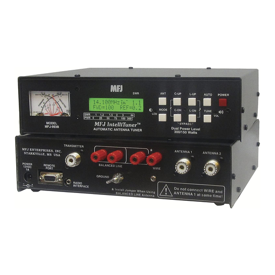
MFJ-993B IntelliTuner Automatic Antenna Tuner Instruction Manual • Transmitter: SO-239 connector for coax cable from transceiver or amplifier. • Ground: Wing-nut terminal for RF ground wire connection. • Balanced Line: Two binding posts for connecting balanced line antennas. To use balanced line antenna, install a jumper as shown to the WIRE binding post.
-
Page 18: Swr/Wattmeter
The meter also indicates various operational states of the tuner. Refer to “Meter Codes and Audible Beeps” on page 21 for more details. The MFJ-993B also includes an SWR bar meter and an audio SWR indicator, selectable by pressing [L- UP] and [L-DN] buttons simultaneously. It also has bar meters for forward and reflected power.
-
Page 19: The Menus
MFJ-993B IntelliTuner Automatic Antenna Tuner Instruction Manual The Menus Main Mode Menus The main mode menus show various tuner settings and status. There are four main mode menus arranged in a “wrap-around” structure. When powered on, tuner operation starts with the main menu that was last used.
-
Page 20: Swr Bar Meter Menu
MFJ-993B IntelliTuner Automatic Antenna Tuner Instruction Manual Figure 10. Power Bar Meter (High Range). Divide scale by 10 Figure 11. Power Bar Meter (Low Range). SWR Bar Meter Menu Shows the frequency, SWR, forward power, and SWR bar meter. A SWR scale is printed just below the display on the front panel.
-
Page 21: Tuner Indicators
MFJ-993B IntelliTuner Automatic Antenna Tuner Instruction Manual 2 3 4 Frequency Indicators: Antenna, IntelliTune Indicators: Memory, Power Level, LC Limit, Range 2 3 4 Indicators: Auto/Semi, StickyTune Forward power in watts Reflected power in watts 2 3 4 Forward power bar meter…
-
Page 22: Lc Limit
MFJ-993B IntelliTuner Automatic Antenna Tuner Instruction Manual • LC Limit: When LC Limit is OFF, a bar appears on the upper-right corner of the Memory indicator (23). • Meter Range: When Auto Range is ON, a two-dot vertical bar segment appears on the lower right corner of the Memory indicator (24), another dot appears on top of this bar segment when the meter range is high, and no dot when the meter range is low (25).
-
Page 23: Setup Mode Menus
Press the [C-DN] or [L-DN] button to decrease or turn off the setting for the current setup menu. Power Level Menu Allows you to set the maximum power level the MFJ-993B can handle to 300 watts or 150 watts SSB/CW. Power level of 300 watts can match antennas with impedances of 6 to 1600 ohms; power level of 150 watts can match a wider impedance range of 6 to 3200 ohms.
-
Page 24: Auto Tune Swr Menu
0.5, 1.0 and 1.5. Refer to Table 2 for meter code. Note: The AUTO button should always be IN (semi-automatic) unless a compatible radio interface cable is connected between the MFJ-993B and your transceiver. This will ensure that the MFJ-993B does not attempt tuning during high-power operation.
-
Page 25: Intellitune Menu
MFJ-993B IntelliTuner Automatic Antenna Tuner Instruction Manual Meter Frequency Range (kHz) Memory Resolution (kHz) 1800 – 2000 75/80 3500 – 4000 5330.5, 5346.5, 5366.5, 5371.5 and 5403.5 5 memory locations 7000 – 7300 10100 – 10150 14000 – 14350 18068 – 18168 21000 –…
-
Page 26: Swr Beep Menu
MFJ-993B IntelliTuner Automatic Antenna Tuner Instruction Manual SWR Beep Menu Turns the audio SWR meter on and off. The audio meter is a series of beeps where one beep indicates SWR of 1.5 or less, two beeps indicate SWR of 1.6 to 2.0, three beeps indicate SWR of 2.1 to 2.5, and four beeps indicate SWR of 2.6 to 3.0.
-
Page 27: Operation
MFJ-993B IntelliTuner Automatic Antenna Tuner Instruction Manual Operation Manual Tuning Manual tuning may be used to “touch up” the tuner’s settings. For example, if the target SWR is set at the default of 1.5, the tuner will stop when a match of 1.5 is found. In all cases, manual tuning gives the user control of the tuner if desired, and the L-Network menu provides a picture of the matching network configuration.
-
Page 28: Table 2. Meter Needle Stationary Codes
MFJ-993B IntelliTuner Automatic Antenna Tuner Instruction Manual Meter Needle Stationary Codes (Meter needles stay at the indicated mark until buttons are released.) Forward 30 Watts Mark 100 Watts Mark 300 Watts Mark [TUNE] + [L-DN] 30 Watts Meter Range Auto Range…
-
Page 29: Transceiver Foldback
Even with foldback, the tuning process can be hard on your transceiver’s finals. When an amplifier is used, the amplifier must be bypassed during tuning. Note: MFJ recommends that a transceiver-specific interface cable be used between the MFJ-993B and your transceiver to ensure that tuning only occurs at low power.
-
Page 30: Antenna System Hints
When the SWR rises, the power handling capability decreases by 1/√SWR and loss also increases. Therefore MFJ recommends that RG-8/U, RG-213, LMR-400 or other high quality coax cables be used between the MFJ-993B output and the antenna. Refer to The Radio Amateurs Handbook and The ARRL Antenna Book for more information.
-
Page 31: Matching Problems
MFJ-993B IntelliTuner Automatic Antenna Tuner Instruction Manual Matching Problems Most matching problems occur when the antenna system presents an extremely high impedance to the tuner. When the antenna impedance is much lower than the feedline impedance, an odd quarter- wavelength feedline converts the low antenna impedance to a very high impedance at the tuner. A similar problem occurs if the antenna has an extremely high impedance and the transmission line is a multiple of a half-wavelength.
-
Page 32: Appendices
MFJ-993B IntelliTuner Automatic Antenna Tuner Instruction Manual Appendices POWER-ON OPERATIONS (Press and hold buttons while turning on the power.) Press and hold to get the firmware version number. C-UP POWER Press and hold L-UP POWER to start the self test.
-
Page 33: Delete Antenna Memory
Remember that both antenna memories will be lost and tuner settings will return to default! Self Test A self-test routine will check the functions of the MFJ-993B. This routine checks the display, the meter, the front-panel buttons, the internal memory and the audio circuitry. During the self-test, you may stop the test by turning off the unit;…
-
Page 34: Table 4. Failure Messages
MFJ-993B IntelliTuner Automatic Antenna Tuner Instruction Manual This test can also be used to test the optional MFJ-993RC Remote Control. Make sure to press both [ANT] and [AUTO] buttons on the MFJ-993B tuner to the in position before starting the self-test, and press the buttons on the MFJ-993RC instead of the front-panel buttons when prompted.
-
Page 35: Power Down Circuit Test
MFJ-993B IntelliTuner Automatic Antenna Tuner Instruction Manual Power-Down Circuit Test When the 12 VDC power to the tuner is turned off, the tuner saves all settings to non-volatile memory. The Power-Down Circuit Test checks the power down detection circuitry. It is recommended that this test be done immediately after the regular self-test described above.
-
Page 36: Setting The Speaker Volume
To calibrate the meter needles, you will need a Phillips screwdriver and a tuning tool or small flat blade screwdriver. WARNING: Never operate the MFJ-993B with its cover removed; dangerous voltages and currents can be present during operation. Never exceed tuner specifications.
-
Page 37: Frequency Counter Calibration
WARNING: Do not touch anything inside the tuner during operation! Serious, painful RF burns can result. WARNING: Never operate the MFJ-993B with its cover removed; dangerous voltages and currents can be present during operation. Never exceed tuner specifications. 1. Turn off the power to the tuner and the transmitter.
-
Page 38: Alinco Radio Interface
5. Push the [POWER] button on the tuner to the in position and then power on the radio. Operation The operation of the MFJ-5124A radio interface is similar to the operation of the EDX-2 described in the Alinco operating manual.
-
Page 39: Icom Radio Interface
Push [PWR] to turn power on again. Operation The operation of the MFJ-5124I radio interface is similar to the operation of the AH-3 or AH-4 described in the Icom radio’s operating manual. 1. Push and hold the [TUNER] button on the radio for one or two seconds to initiate automatic tuning process.
-
Page 40: Kenwood Radio Interface
Press the [CLR] key to return to normal operation. Operation The operation of the MFJ-5124K radio interface is similar to the operation of the AT-300 described in the Kenwood radio’s operating manual. 1. Press and hold the [AT TUNE] button on the radio for one second to initiate automatic tuning process.
-
Page 41: Yaesu Radio Interface/Mfj-5124Y
8. Push the [POWER] button on the tuner to the in position and then power on the radio. Operation for FT-100 The operation of the MFJ-5124Y radio interface is similar to the operation of the FC-20 described in the Yaesu radio’s operating manual.
-
Page 42: Connections For Ft-450
8. Push the [POWER] button on the tuner to the in position and then power on the radio. Operation for FT-450 The operation of the MFJ-5124Y radio interface is similar to the operation of the FC-30/-40 described in the Yaesu radio’s operating manual.
-
Page 43: Connections For Ft-857 Or Ft-897
7. Push the [POWER] button on the tuner to the in position and then power on the radio. Operation for FT-857 or FT-897 The operation of the MFJ-5124Y radio interface is similar to the operation of the FC-30 described in the Yaesu radio’s operating manual.
-
Page 44: Connections For Ft-950
8. Push the [POWER] button on the tuner to the in position and then power on the radio. Operation for FT-950 The operation of the MFJ-5124Y radio interface is similar to the operation of the FC-40 described in the Yaesu radio’s operating manual.
-
Page 45: Yaesu Radio Interface/Mfj-5124Y2
MFJ-993B IntelliTuner™ Automatic Antenna Tuner. With this interface, control signals are connected between the radio and the tuner. With this cable the operator can control the tuner and radio with a single push of the [TUNE] button on the front panel of the MFJ-993B. Connections for FT-847 1.
-
Page 46: Yaesu Radio Interface/Mfj-5124Y3
Press [ENT] to exit the Menu mode. 2. Insert the 3.5 mm stereo phone plug into the MFJ-993B RADIO INTERFACE jack. 3. Connect the 3.5 mm mono plug on the MFJ-5124Y3 to the REMOTE jack on the rear panel of the transceiver.
-
Page 47: Operation For Ft Dx -9000 Series Of Radios
If you press the [MENU] key momentarily, the new setting will not be saved. 2. Insert the 3.5 mm stereo phone plug into the MFJ-993B RADIO INTERFACE jack. 3. Connect the RCA plug on the MFJ-5124Y4 to the TX REQ jack on the rear panel of the transceiver.
-
Page 48: Operation For Ft-2000 Series Of Radios
2. Insert the 3.5 mm stereo phone plug into the MFJ-993B RADIO INTERFACE jack. 3. Connect the RCA plug on the MFJ-5124Y4 to the TX REQ jack on the rear panel of the transceiver. 4. Connect a 12V 1000 mA DC source to the MFJ-993B.
-
Page 49: In Case Of Difficulty
If you have any problem with this unit first check the appropriate section of this manual. If the manual does not reference your problem or your problem is not solved by reading the manual, you may call MFJ Technical Service at 662-323-0549 or the MFJ Factory at 662-323-5869. You will be best helped if you have your unit, manual and all information on your station handy so you can answer any questions the technicians may ask.
-
Page 50: Circuit Block Diagram
MFJ-993B IntelliTuner Automatic Antenna Tuner Instruction Manual 2005-2012 MFJ Enterprises, Inc.
-
Page 51
MFJ Enterprises, Inc. warrants to the original owner of this product, if manufactured by MFJ Enterprises, Inc. and purchased from an authorized dealer or directly from MFJ Enterprises, Inc. to be free from defects in material and workmanship for a period of 12 months from date of purchase provided the following terms of this warranty are satisfied. -
Page 52
MFJ ENTERPRISES, INC. MFJ-993B Manual 300 Industrial Park Road Version 2B Starkville, MS 39759 Printed In U.S.A. 03/2012…
Инструкция по эксплуатации (мануал) на русском языке, для автоматического антенного тюнера MFJ-993B
Инструкция выполнена профессиональным переводчиком — радиолюбителем, в оригинальном качестве.
Инструкция поставляется в виде книги — распечатана на листах формата А4 и сшита пружинным переплетом.
Инструкция содержит 38 страниц.
Внимание!!!
Приобретая в нашей компании автоматический антенный тюнер MFJ-993B, вы получаете данную инструкцию бесплатно!!
Предупреждение!!!
Все права защищены! Все права на данный перевод инструкции по эксплуатации автоматического антенного тюнера MFJ-993B, являются собственностью компании «Радиоэксперт»! Ничто из нее, приобретенной или полученной бесплатно от компании «Радиоэксперт», не может быть перепечатано, заложено в компьютерную память или скопировано в любой форме — электронной, механической, фотокопии или какой-то другой — без письменного разрешения компании «Радиоэксперт». Распространение данной инструкции всей или любых ее частей, платное или бесплатное, в любой форме ЗАПРЕЩЕНО!!!

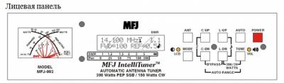
Антенный
тюнер MFJ-993B IntelliTuner™
позволяет быстро настроить в автоматическом режиме любую антенну: симметричную,
несимметричную или однопроводную. Тюнер MFJ-993B — это сложный автоматический
прибор с КСВ-/ваттметром. антенным коммутатором на две антенны и симметрирующим
трансформатором тока 4:1 для симметричных линий.
Уникальные алгоритмы InstanlRecall™, JntelliTune™ и AdaptiveSearchразработанные компанией MFJ, и постоянная память VirtualAntenna™ более чем на 20 ООО настроек обеспечивают быструю автоматическую
настройку. Каждая их двух антенн имеет четыре банка памяти; каждый банк
позволяет сохранить в постоянной памяти более 2500 настроек тюнера.
Тюнер строить очень просто, нажать нижнюю справа кнопку настройки и подержать до сигнала, в момент сигнала стрелка дёрнится влево. (стрелки визуально показывают что происходит при нажатии, + звуковой сигнал)
подаёте несущую, ватт 10 и ждёте. После треска тюнер настроится в пределах 1.3-1.4. После этого можно подогнать как душе угодно ёмкостью и катушкой (кнопки на морде ап-даун)
Что бы засейвить в памяти РУЧНУЮ настройку надо нажать 3 кнопки одновременно. «TUNE+L-DN+C-DN» В режиме автомат он сам всё запоминает.
Т.е. например строитесь в авторежиме на 7.100, тюнер потрещав секунд 20 настраивает КСВ=1.4 и ниже не может. (это если неисправная, убирая антенна или её жалкое подобие) Кнопками ёмкости и катушки подгоняете КСВ как угодно, например 1.3 (если получится) и жмёте эти 3 кнопки одновременно. Тюнер пикнет, стрелки обе подскачут. Всё. сохранена ячейка. Теперь после переключения с любой частоты на 7,100 и подаче несущей (можно при 100вт. очень тихонько алёкнуть ) тюнер вытащит настройку для этой частоты принудительно сохранённую нажатием 3-х кнопок.
Режим обход включается кнопкой «TUNE» но только тогда, когда нажата/утоплена кнопка «AUTO».
Ёмкость можно «перекидывать» как на сторону антенны так и на сторону трансивера, всё зависит от сопротивления нагрузки. В режиме автомат тюнер сам перебирает этот конденсатор…
Вобщем более половины кнопок и настроек не нужны для повседневной работы. Ручной режим так же не особо востребован.
Как строить с 756, думаю надо почитать инструкцию к 756, так как после подключения девайса трансивер видит этот тюнер как родной айкомовский и юзает его так же.
Вобщем после месяца тюнер у Вас приживётся к Вашему антенному хозяйству и перестанет трещать…
Только надо порог автосрабатывания выставить и работу до 150вт.
Если выставлена 300РЕР то 6-1600 Ом, если 150 то 6-3200 Ом. ( в отличии от 929, который только 6-1600 умеет) Если этого мало то продаётся балун 1:4.

MFJ-826B Digital SWR/Wattmeter
THE BASICS
Instruction Manual
Contents
THE MENUS
APPENDICES
MFJ-826B Digital SWR/Wattmeter
FIGURES
TABLES
Instruction Manual
MFJ-826B Digital SWR/Wattmeter
The Basics
Introduction
Instruction Manual
PeakHold
TrueActive true
QRPCubs
Features
Specifications
MFJ-826B Digital SWR/Wattmeter
Front Panel
Instruction Manual
LCD Display:
LCD Contrast Control:
MODE Button:
PEAK Button:
MFJ-826B Digital SWR/Wattmeter
ALM LED:
ALARM Button:
Instruction Manual
POWER Button:
WARNING: Do not turn the power on and off rapidly, otherwise the unit’s setting memory can be corrupted and the unit will have to be reset to factory defaults.
Back Panel
Power:
WARNING: Do not apply voltages greater than 18 volts to this unit, or permanent damage to the unit may result.
RS-232:
Ground:
Antenna:
Transmitter:
MFJ-826B Digital SWR/Wattmeter
Installation
Instruction Manual
The Menus
Main Mode Menus
Note: In sideband mode, the frequency readout on the wattmeter display jumps around to different frequencies while transmitting and stops on another frequency when un-keyed. This is normal and is a characteristic of sideband mode, because sideband signals jump around in frequency and power.
Digital Wattmeter Menu
Power Bar Meter Menu
MFJ-826B Digital SWR/Wattmeter Instruction Manual
SWR Bar Meter Menu
SWR/Power Bar Meters Menu
SWR
MFJ-826B Digital SWR/Wattmeter Instruction Manual
Setup Mode Menus
MFJ-826B Digital SWR/Wattmeter
Alarm SWR Menu
Beep Menu
Factory Defaults
Appendices
Instruction Manual only
WARNING: If the MFJ-826B is not behaving properly or acting erratic, try resetting the unit to factory defaults.
MFJ-826B Digital SWR/Wattmeter
Self Test
Note: Performing the self-test will reset the unit to its factory default settings. only
Instruction Manual
Failure
Message
Indicates
MFJ-826B Digital SWR/Wattmeter
SWR Bridge Calibration
Instruction Manual
WARNING: Do not touch anything inside the wattmeter during operation! Serious, painful RF burns can result.
WARNING: Never operate the MFJ-826B with its cover removed; dangerous voltages and currents can be present during operation. Never exceed wattmeter specifications.
both
MFJ-826B Digital SWR/Wattmeter
Frequency Counter Calibration
Instruction Manual
WARNING: Do not touch anything inside the wattmeter during operation! Serious, painful RF burns can result.
WARNING: Never operate the MFJ-826B with its cover removed; dangerous voltages and currents can be present during operation. Never exceed wattmeter specifications.
exactly both
In Case of Difficulty
Technical Assistance
Technical Service MFJ Factory
MFJ
L
IMITED
12 M
ONTH
W
ARRANTY
MFJ Enterprises, Inc. warrants to the original owner of this product, if manufactured by MFJ Enterprises,
Inc. and purchased from an authorized dealer or directly from MFJ Enterprises, Inc. to be free from defects in material and workmanship for a period of 12 months from date of purchase provided the following terms of this warranty are satisfied.
1. The purchaser must retain the dated proof-of-purchase (bill of sale, canceled check, credit card or money order receipt, etc.) describing the product to establish the validity of the warranty claim and submit the original or machine reproduction of such proof of purchase to MFJ Enterprises, Inc. at the time of warranty service. MFJ Enterprises, Inc. shall have the discretion to deny warranty without dated proof-of-purchase. Any evidence of alteration, erasure, or forgery shall be cause to void any and all warranty terms immediately.
2. MFJ Enterprises, Inc. agrees to repair or replace at MFJ’s option without charge to the original owner any defective product under warrantee provided the product is returned postage prepaid to
MFJ Enterprises, Inc. with a personal check, cashiers check, or money order for $10.00 covering postage and handling.
3. This warranty is NOT void for owners who attempt to repair defective units. Technical consultation is available by calling the Service Department at 662-323-0549 or the MFJ Factory at
662-323-5869.
4. This warranty does not apply to kits sold by or manufactured by MFJ Enterprises, Inc.
5. Wired and tested PC board products are covered by this warranty provided only the wired and
tested PC board product is returned. Wired and tested PC boards installed in the owner’s cabinet or connected to switches, jacks, or cables, etc. sent to MFJ Enterprises, Inc. will be returned at the owner’s expense unrepaired.
6. Under no circumstances is MFJ Enterprises, Inc. liable for consequential damages to person or property by the use of any MFJ products.
7.
Out-of-Warranty Service: MFJ Enterprises, Inc. will repair any out-of-warranty product provided the unit is shipped prepaid. All repaired units will be shipped COD to the owner. Repair charges will be added to the COD fee unless other arrangements are made.
8. This warranty is given in lieu of any other warranty expressed or implied.
9. MFJ Enterprises, Inc. reserves the right to make changes or improvements in design or manufacture without incurring any obligation to install such changes upon any of the products previously manufactured.
10. All MFJ products to be serviced in-warranty or out-of-warranty should be addressed to:
MFJ Enterprises, Inc.
300 Industrial Park Road
Starkville, Mississippi 39759 USA
and must be accompanied by a letter describing the problem in detail along with a copy of your dated proof-of-purchase.
11. This warranty gives you specific rights, and you may also have other rights which vary from state to state.