-
Bookmarks
Quick Links
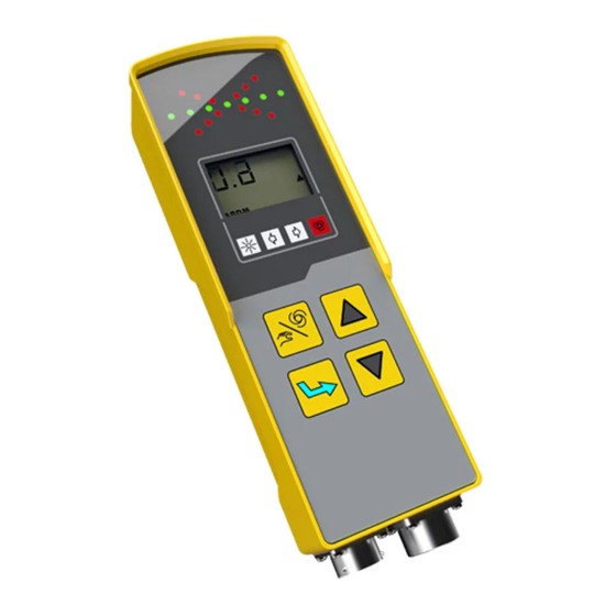
USER MANUAL
MOBA-Matic, CAN, as of Version
V2055
MMC-1000
Levelling System for paver, milling machines
and other mobile applications
Further applicable documents:
Specifications:
04-03-00415 | 04-21-21010 | 04-25-10300
04-21-10100 | 04-21-30070 | 04-60-11311
04-21-10102 | 04-21-40110 |
CE declaration of conformity
ENGLISH
Summary of Contents for MOBA MOBA-Matic MMC-1000
-
Page 1
USER MANUAL MOBA-Matic, CAN, as of Version V2055 MMC-1000 Levelling System for paver, milling machines and other mobile applications Further applicable documents: Specifications: 04-03-00415 | 04-21-21010 | 04-25-10300 04-21-10100 | 04-21-30070 | 04-60-11311 04-21-10102 | 04-21-40110 | CE declaration of conformity… -
Page 2
All rights reserved. No part of these documents may be reproduced or transmitted for any purpose without express written permission from MOBA, irrespective of the manner or the means by which this occurs. Please read this user manual in its entirety before initial use and observe all the safety notices contained within. -
Page 3
Table of contents Table of contents Table of contents ………………3 General information ………………8 Information relating to the user manual …………. 8 Explanation of symbols …………….10 Limitation of liability …………….. 11 Copyright protection …………….12 Other applicable documents …………..12 Spare parts ………………… -
Page 4
Table of contents Transport, packaging and storage ………….. 29 Transport inspection …………….29 Transport ………………..29 Storage ………………..30 Product description ………………31 Structure and function …………….33 Structure ………………..33 Function description …………….35 Operating and display elements, operating modes ……..42 The control and display elements of the digital controller …… -
Page 5
Table of contents Operation ………………… 67 Safety notices ………………67 8.1.1 Switching on and switching on message ………… 68 8.1.2 Controller-side display …………….69 8.1.3 Zero adjustment ………………71 8.1.4 Differences in the operation variants …………73 8.1.5 Retrofitting ………………..76 8.1.6 Switching off ……………….. -
Page 6
Table of contents 8.5.4 Controlling with the Digi Rotary Sensor (ground sensing)) ……121 Working with the Dual-Sonic …………..123 8.6.1 Assembling and setting up …………..123 8.6.2 Controlling with the Dual-Sonic …………..124 Working with the wire rope sensor …………125 8.7.1 Description ………………… -
Page 7
Table of contents Declaration of conformity …………… 161… -
Page 8
Information relating to the user manual General This user manual contains fundamental information that is to be observed during the operation and maintenance of the MOBA- Matic. A prerequisite for safe operation is the compliance with all specified safety and handling instructions. -
Page 9
In this case, your MOBA supplier will always have a current copy of the user manual ready for you. We do not accept liability for malfunctions, faults, failures and resulting damage. -
Page 10
General information Explanation of symbols Warning Warning notices in this user manual are marked by symbols. notices These notices are described with signal words which express the extent of the danger. These notices must be strictly complied with and acted upon diligently in order to prevent accidents as well as injuries to people and property damage. -
Page 11
General information Step by Step Step by step instructions, which have to be executed by the operating personnel, are enumerated. 1) … 2) … 3) … Bullet points Enumerations are marked with a black dot. Limitation of liability All instructions and information in this user manual were compiled in observation of the applicable standards and regulations, the current state of the art as well as our many years of expertise and experience. -
Page 12
Additional information on the installation of the Big Sonic -Skis® and the structure and the setting of the parameter menus of the MOBA-Matic can be found in the following documentation: 10-02-02100 Assembly instructions(s) Big Sonic-Ski® 10-02-00862 Parameter setting MOBA-Matic CAN… -
Page 13
General information Final decommissioning / disablement During the final decommissioning, the components of the MOBA — Matic must be rendered by disablement to protect against recommissioning, particularly by unauthorised third parties. Switch off the power supply of the product. Disconnect all poles of the product. -
Page 14
General information CAUTION! Risk of injury due to improper disposal of the product! The burning of plastic parts releases poisonous gases which may cause illness in persons. For these reasons: • Properly dispose of product in accordance with the applicable, national, country-specific disposal regulations. CAUTION! Risk of injury due to improper disposal of the product! Careless disposal enables unauthorised persons to use the… -
Page 15
This user manual contains no statement of guarantee. The guarantee provisions are part of the MOBA MOBILE AUTOMATION AG (MOBA) “Terms and Conditions of Sale and Delivery”. Customer Service Your MOBA Dealer will be pleased to assist with technical requests. -
Page 16
Fundamental safety instructions 2 Fundamental safety instructions General This section provides an overview of all the important aspects of safety for an optimal protection of the personnel as well as for the safe and failure-free operation. The information should place the operators and users in the position to be able to recognise the danger in time and to prevent it as far as possible in advance. -
Page 17
Fundamental safety instructions Intended use 2.1.1 Intended use of the machine The MOBA-Matic is designed and constructed exclusively for the intended use as described here. • Automatic control of the tool of the machine (e.g. the planks of a paver) in height and slope in accordance with the reference height, reference line or setpoint value. -
Page 18
Operating limits The MOBA-Matic is designed for use in an atmosphere appropriate for permanent human habitation. It must not be used in aggressive or explosive environments. Local safety authorities and safety management personnel are to be contacted by the system owner before working in hazardous environments, near electrical systems or in similar situations. -
Page 19
Fundamental safety instructions Modifications and rebuilding the product To avoid hazards and to ensure optimum performance, neither modifications nor additions or rebuilding may be made to the product unless explicitly approved by the manufacturer. Contents of the user manual Any person who is assigned with performing works at or with the product must have read and thoroughly understood the user manual before beginning work. -
Page 20
Fundamental safety instructions Responsibility of the system owner The MOBA-Matic will be utilised in the commercial sector. The product owner is therefore subject to the legal obligations regarding occupational safety. In addition to the occupational safety notices in this user manual, the… -
Page 21
Fundamental safety instructions 2.4.1 Operating personnel WARNING! Risk of injury from insufficient qualification! Improper use of the product can result in serious personal injuries and material damages. For these reasons: • Particular activities must only be executed by the people stated in the respective chapters of this user manual. -
Page 22
Fundamental safety instructions facilities are required. Special dangers General In the following section, residual risks are listed that were identified in the risk analysis. Observe the safety notices and warning notices listed here and in the following chapters of this manual to reduce health hazards and avoid dangerous situations. -
Page 23
• Remove objects from the working range of the machine or tool. • During operation, do not reach into moving components. • The MOBA-Matic must always be switched off when leaving the driver´s seat or the machine. • Never perform any works on the sensors when the system… -
Page 24
Fundamental safety instructions Protruding machine parts CAUTION! Risk of injury from protruding machine parts! Retrofitted system components (e.g. sensors) could protrude over the typical machine dimensions. This can result in injuries and material damage. For these reasons: • Make certain that the machine is operated by a qualified and experienced operator. -
Page 25
Fundamental safety instructions Lack of instructions WARNING! Risk of injury from missing or incomplete instructions! Missing and incomplete instructions could lead to operating errors or improper use. Accidents with severe personal injuries or severe damage to property and the environment could thereby result. For these reasons: •… -
Page 26
Fundamental safety instructions Insufficient safeguarding WARNING! Risk of injury due to inadequate safeguarding! Inadequate safeguarding of the construction site and for the location of a component, e.g. the laser transmitter, can lead to dangerous situations in road traffic and at the construction site. For these reasons: •… -
Page 27
The MOBA-Matic has no own, superordinated safety device. However: The controller on the MOBA-Matic is equipped with an input which can be accessed from an external controller. The processor in the controller monitors the applied voltage on Pin A of the 12 -pin device plug socket. -
Page 28
Fundamental safety instructions Behaviour in the event of dangerous situations and accidents Preventative measures Always be prepared for accidents and fire! Have first aid gear (first aid box, blankets, etc.) and fire extinguishers accessible at all times. Familiarise personnel with accident reporting, first aid and rescue equipment. -
Page 29
Transport, packaging and storage 3 Transport, packaging and storage Transport inspection To ensure sufficient protection during shipment, the products are carefully packaged. Upon receipt of delivery, immediately inspect for completeness and for transport damage. In the event of externally recognisable transport damages, proceed as follows: Do not accept the delivery or do so only under reservation. -
Page 30
Transport, packaging and storage Storage Only store the product in well ventilated, dry rooms. During storage, protect against moisture. Use the original packaging for this purpose if possible. Avoid large temperature fluctuations during storage. The formation of condensation can impair the function. Always observe the storage temperature limits for products, especially in the Summer when the equipment is kept in the vehicle interior. -
Page 31
Product description 4 Product description The MOBA-Matic is a universal control and regulating system for all types of construction machines. The extensive range of sensors for distance and slope measurement, the great comfort and a high level of operating safety make the MOBA-Matic one of the most flexible and… -
Page 32
Product description Identification of Every component of the system (except for the wiring) is the products provided with a type label. The type label contains the CE marking (4), the device designation (2), the article number of the product (1) as well as a consecutive serial number (3). -
Page 33
In this section, you will learn more about the structure of the MOBA-Matic and its fundamental functionality. Structure The heart of the MOBA-Matic system is the digital controller. For each control loop or each side of the machine, a separate controller and at least one corresponding sensor will be required. -
Page 34
Structure and function Configuration example for Big Ski Digital controller Distribution box Slope sensor Utilisable sensors (Sonic-Ski, DUAL-Sonic …) Big Ski framework… -
Page 35
Structure and function Function description The MMC-1000 (04-25-10300) digital controller includes all the required buttons, optical indicators for controlling the system on which, at all times, the current status of the system and the power outputs for the valves can be read out. -
Page 36
Structure and function The multiple ultrasonic sensor SKIS-1500 Sonic-Ski plus (04-21-10120) works with five ultrasonic sensors. A sixth sensor is used for temperature compensation. This can therefore capture a reference (ground, string etc.). The SKIS-1500 Sonic- Sonic-Ski plus covers a measurement range from 25 cm up to Ski plus 150 cm in ground sensing and up to 100 cm in string line sensing. -
Page 37
Structure and function The principle of the averaging, which has already been recognised by Sonic-Ski® plus will be acquired again by Big Sonic-Ski®. There will be up to 3 sensors assembled as divided on the machine length — or even more by using a corresponding mechanism — and electrically connected via a distribution box. -
Page 38
Structure and function The ROPS-0900 (04-21-30070) string-line sensor acquires the measured value via a pull-out steel rope and is utilised frequently when working with the milling machine. ROPS-0900 String-line sensor It is utilised for the distance measurement. The DUAS-1000 (04-21-10100) Dual-Sonic sensor is a sensor for distance measurement and works with ultrasonic technology. -
Page 39
Connects 2 controllers to a central connection. (04-03-00080) Adapter box Option / accessories and connection elements The complete functional scope of the MOBA-Matic is available with two controllers. The control panel now functions as an equal parallel and thereby secondary operating device. (04-25-53301) -
Page 40
Structure and function Option / accessories and connection elements Article Designation Comment number Coil cable, machine 04-02-02560 12-pin Bayonet lock, 10-pin, 3 m CAN-Controller All pins wired (Power-CANBox) Machine 04-02-02561 12-pin Bayonet lock 10-pin, 3 m. Only +, -, UP/DOWN wired 04-02-02563 12-pin Bayonet lock 7-pin, 3 m Blaw-Knox Coil cable, sensor… -
Page 41
Determining a Corrective Actual value value deviation measures Measurement of the actual value In the case of the MOBA-Matic, this means: e.g. uneven ground Comparison of the Adjustment of Setpoint value values in the MOBA- the tool setting with the… -
Page 42
Operating and display elements, operating modes 6 Operating and display elements, operating modes General In this section you will learn more about all the elements required for professional, correct operation of the product, which are described in the Sections “Commissioning” and “Operation”. The control and display elements of the digital controller The front of the digital controller contains all the necessary buttons, some function LEDs and a LC display for the advanced… -
Page 43
Operating and display elements, operating modes 6.1.1 The LED arrow The LED arrow enables the status of each of the controlled valve output to be visible for the operator. Particularly in the case of a larger distance from the operator to the controller, or with stronger sunlight, the LED arrow is a useful display element. -
Page 44
Operating and display elements, operating modes 6.1.2 The LC Display The 3 1/2 digit liquid crystal display is easy to read out due to its integrated lighting, even in poor light conditions. The symbols of the displays have the following meaning The LIFT arrow indicates that the controller output for LIFT is currently active. -
Page 45
Operating and display elements, operating modes The actual value and the setpoint values of the active sensor will be illustrated with a prefix, the setpoint value is also available with a physical measurement unit. The prefix indicates whether it is a positive or a negative numerical value. -
Page 46
(1) This signal status also occurs when the automatic for the MOBA-Matic has been locked with the help of the function “External Hand”. The valve outputs are then switched off and the operation of the digital controller is inhibited. -
Page 47
Operating and display elements, operating modes 6.1.3 The control buttons: For the operation of the fundamental control functions of the MMC-1000, only 4 buttons are required. These buttons enable a simple operation and are only provided for some settings with an additional function. Up &… -
Page 48
Operating and display elements, operating modes Automatic / Manual buttons + Enter button By simultaneously pressing both these buttons, the call up of the user menus is executed. Behind them are parameters such as “Sensor selection”, “Sensitivity setting”, “Control window”, “Unit of length”, “Sampling factor”… -
Page 49
Operating and display elements, operating modes The display elements of the prop. Laser receiver The laser receiver is equipped with a LED arrow (1) — similar to the digital controller. Depending on the operating mode in which the digital controller is located and which it is connected to, the LED arrow of the laser receiver can have a different function. -
Page 50
Operating and display elements, operating modes Display of the prop. Laser receiver in the “Manual” mode In the “Manual” operating mode, the LEDs of the laser receiver are utilised to display for the operator how the sensor must be displaced so that the laser beam strikes in the middle of the reception area. -
Page 51
Operating and display elements, operating modes Display of the prop. Laser receiver in the “Automatic” mode In the “Automatic” mode, the LEDs of the laser receiver are used to visualise the status of the actuated valve output for the operator. They now work similar as analogue to LED arrow of the digi tal controller. -
Page 52
(1) This mode occurs when the optional operator variant with semi -automatic is activated from your MOBA dealer (also refer to the next page) or when the MOBA — Matic system has been locked with the aid of the “External Hand” function. -
Page 53
Operating and display elements, operating modes Operating variants Your MOBA dealer can assist you with the operation of the controller and select from three variants. The operations then differentiate as follows: 6.5.1 Standard operation The default setpoint is executed with the up/down buttons in the “Automatic”… -
Page 54
Operating and display elements, operating modes By simultaneously pressing the Enter button in conjunction with the Up button or the Down button, the displayed setpoint can be amended without influencing on the tool position. Switching between the “Manual”, “Semi-automatic” and “Automatic”… -
Page 55
Installation and commissioning 7 Installation and commissioning General The content of this section should support the authorised personnel for the installation and commissioning with these work steps. Safety notices The installation and commissioning of the product must only be executed by instructed and qualified professional personnel. CAUTION! Danger caused by faulty installation! Unauthorised modifications on, and rebuilding the machine during… -
Page 56
Assembly site Due to the wide range of application possibilities for the MOBA — & installation Matic and the diversity of different machines available, only… -
Page 57
Installation and commissioning The slope sensor Install the slope sensor parallel to the lower edge of the tool on a machine part that can adjust for all the slope amendments of the tool to the same degree. This therefore creates the measurement value of the sensor exactly with the slope of the tool. -
Page 58
(e.g. On the tow arm for pavers or on the chassis for milling machines). This securing pipe — with a round mounting for the MOBA grade sensors — should be adjustable in height, swivelling and can be moved horizontally. -
Page 59
Installation and commissioning The Big Sonic-Ski® junction box The junction box should be mounted in such a way that simple wiring to the controller and the sensors is possible. The connections for the sensors should always point downwards so that no water can penetrate into the junction box. Inputs which are not required must be sealed with dust protection caps. -
Page 60
Installation and commissioning The laser receiver The assembly of a laser receiver on the mast pipe is relatively simple: Open the mounting clamp. Slide the laser receiver over the mast pipe. Close the mounting clamp. -
Page 61
A pipe diameter of the mast from 30 mm up to 46 mm enables a MOBA laser receiver to be securely attached. Regardless of which mast type is utilised, it must be ensured that this is positioned in the typical vertical working position of the tool. -
Page 62
Area Network). The Bus technology requires the completion of the Bus via resistors. In order to make the wiring as easy as possible, MOBA has already provided a part of its sensor cable already with these terminating resistors. In order to differentiate this cable from other cables, the jacket material is coloured yellow and the cable glands on the connectors are grey. -
Page 63
Installation and commissioning Connection diagram without cross-connection:… -
Page 64
Installation and commissioning Connection diagram with cross-connection via junction boxes:… -
Page 65
Installation and commissioning Devices: Article number Designation 04-25-10300… Digital controller 04-21-21010 Slope sensor 04-03-00415 Junction box for Big Ski (CAN) for averaging with up to 3 sensors 04-21-10020 Sonic-Ski (CAN) 04-21-10120 Sonic-Ski plus (CAN) 04-21-10130 Sonic-Ski-plus (CAN / PWM) 04-21-40110 Rotary sensor 04-60-11311 Laser receiver… -
Page 66
If the system has been retrofitted, please contact your MOBA dealer so that they can support you during the commissioning of the MOBA-Matic. -
Page 67
Operation 8 Operation General The descriptions in this section should guide you through the operation of the product. These comprise • The safe operation of the product • The full utilisation of all the possibilities of the product • The economic use of the product Safety notices The product must only be operated by trained and instructed people. -
Page 68
Always ensure that when you turn on the MOBA-Matic that person or object is present in the area of the tool or in the area of moving parts for controlling the tool. -
Page 69
Operation A display test will be executed after switching on the digital controller. All of the segments of the LC display, all luminous diodes of the LED display and all 4 function lamps will therefore be controlled for approximately 2 seconds. Should any signs, icons or characters be missing on the display or luminous diodes do not illuminate, then notify the customer service. -
Page 70
Operation Sensor identification After the controller-side display, the digital controller indicates twice, in an alternating display representation, the abbreviation of the sensor which was last worked with. The abbreviations of the individual sensors are described in the sections of this manual for which operation they deal with. -
Page 71
Operation 8.1.3 Zero adjustment Before describing the works with the different grade sensors on the following pages, the term zero adjustment must be initially explained at this point. For every new work project or always after a grade sensor has been assembled or dismantled, their current measured value should be adjusted to zero. -
Page 72
Operation Adjustment Adjustment height height The zero adjustment is only effective for grade sensors and when the digital controller is also located in the “Manual” operating mode. If the tool and sensor(s) are set-up on the adjustment height, then you should proceed with the zero adjustment as follows: 3) Select in the sensor selection for the digital controller for the grade sensor to be adjusted. -
Page 73
Operation 8.1.4 Differences in the operation variants Your MOBA dealer can assist you with the operation of the controller and select from three variants. The operations then differentiate as follows: STANDARD Manual LED off Control outputs active No setpoint adjustment… -
Page 74
Operation SEMI-AUTOMATIC (setpoint value adjustment without activated controller outputs) Manual LED off Control outputs active No setpoint adjustment Semi-automatic LED off Control outputs are inactive Setpoint value adjustment possible Semi-automatic LED off Control outputs active Setpoint value adjustment possible Setpoint value Display value The switching between adjustment… -
Page 75
Operation AUTO ZERO Setpoint value adjustment Use the UP/DOWN buttons to select the setpoint value amendment. The setpoint value amendment will be executed in automatic operating mode after respectively pressing again in 2 mm steps. -
Page 76
“manual” operating mode with every switching on, also when the “Automatic” operating mode was switched on when the system was turned off. Always still turn the MOBA-Matic to the “Manual” operating mode even when leaving the machine. For longer downtime periods and at the end of the works, the power supply must be disconnected and the system dismantled or be reliably secured against being switched on again. -
Page 77
Operation User menu Important parameters and setting options for the behaviour of the system in general and for the operation of the individual sensor types can be found in the user menu for the controller in specialised summaries. As different as the system can be compiled (depending on the application and the associated selection of sensors), the user menu also presents itself very differently. -
Page 78
Operation The user menu will be called up from the work menu. The call up of the By pressing the UP The user menu first parameter is or the DOWN can be exited executed by buttons, the again at any time simultaneously parameter values will by pressing the… -
Page 79
Operation Graphical representation of the user menu… -
Page 80
Operation 8.2.1 Sensor selection If multiple sensors are connected at the same time on one side of the machine and thus on the CAN Bus of one controller, then the desired sensor can be selected in the user menu under the menu item “Sensor selection”… -
Page 81
Your MOBA dealer has the possibility to amend the basic setting of the digital controller in such a way that instead of the parameter “Sensitivity”, the control parameters “Dead band” and “Prop band”, which are concealed behind this parameter, can be displayed. -
Page 82
Operation … until the display Simultaneously The value will be Working mode actuate the A/M switches back and increased and/or will be switched button and the forth between the reduced by back to by Enter button abbreviation for the actuating the UP or actuating the A/M several times. -
Page 83
Operation Sensitivity tables for proportional and servo valves: Sensitivity Dead Prop band Sensitivity Dead Prop band (mm) band band (mm) (mm) (mm) 46.0 0.18 2.10 41.0 0.16 1.90 36.0 0.14 1.70 31.0 0.12 1.50 26.0 0.10 1.30 21.0 0.08 1.10 16.0 0.06 0.90… -
Page 84
Operation Sensitivity tables for the switching mode: Sensitivity Dead Prop band Sensitivity Dead Prop band band (mm) band (mm) (mm) (mm) 18.0 18.0 16.0 16.0 14.0 14.0 12.0 12.0 10.0 10.0 Dual-Sonic-Sensor, Sonic-Ski® Cable sensor and rotary sensor plus, Big Sonic-Ski® Sensitivity Dead Prop band… -
Page 85
Operation 8.2.3 Display for cross slope If a slope sensor is connected to the CAN-Bus but a grade sensor is selected as the active sensor for this controller (also refer to item 8.2.1 “Sensor selection”, then the current measured cross slope will be displayed in the operator menu as the third point. -
Page 86
Operation 8.2.4 3D setpoint assignment If the controller receives external 3D setpoint settings (for example, because a 3D-control with GPS or total station is integrated), then it can be selected here whether these should be utilised for the controlling or whether the default should still be executed in the conventional way by manual entries made by the operator using the keyboard. -
Page 87
Operation 8.2.5 Control window This menu item is only then displayed when a grade sensor is active. Erratic amendments in the measured value of a sensor can occur due to various reasons. Causes can be both negligence of the operating personnel (obstacles in the sound beam of an ultrasonic sensor, crossing over a string line holder etc.) as well as technical errors (reference string is torn, etc.). -
Page 88
Operation The variable for the symmetry around the working point of the control window is adjustable. The setting will be executed, depending on the physical measuring unit for the distance measurement, in 0.1 cm, 0.1 inch or 0.01 feet increments. The set value for the control window describes a range around the working point;… -
Page 89
Before a sampling factor can be entered, this must of course be initially determined. With the necessary physical principles here: In most of the applications for which the MOBA-Matic was conceived, the height adjustment of the tool to be regulated is… -
Page 90
Operation The Positions 1, 2 and 3 on the adjacent diagram specify mounting points for the grade sensors, whereby the Position 1 also corresponds to the tool centre point. The position of the adjuster (a hydraulic cylinder can be on every optional position here and has no influence for the sampling factor). -
Page 91
Operation Otherwise it behaves for the mounting points 2 and 3. Change in height of the sensor… … and thereby… …resulting change in height of the tool Let us initially consider the mounting position 2: The same change in height on the tool as previously will only create a minimal change in height of the sensor here, as it is mounted considerably closer to the pivotal point. -
Page 92
Operation Entering the sampling factor … until the display Simultaneously The value for the Working mode will actuate the A/M switches back and sampling factor be switched back button and the forth between the will be adjusted by to by actuating the Enter button abbreviation for actuating the UP… -
Page 93
Operation 8.2.7 Hydraulic kit setting Hydraulic dataset Should the MOBA-Matic be utilised on different machines, then trained specialised personnel can enter hydraulic parameter settings for up to x different machine types (the maximum possible number of hydraulic kits can be limited in the basic setting of the digital controller by your MOBA dealer). -
Page 94
Operation Entering the hydraulic kit … until the display Simultaneously There will be a Working mode actuate the A/M switches back and switching between will be switched button and the forth between the the saved hydraulic back to by Enter button abbreviation for kits when the UP or actuating the… -
Page 95
Operation Working with the slope sensor 8.3.1 Description The slope sensor operates with a highly precise, electro — mechanical measuring unit and is used for the acquisition of the slope for the tool. Sensor identification: When the system is switched on, or with a sensor change, the illustration in the controller display alternates (changes) between the abbreviation for the Digi-Slope sensor and the side detection (right = engl.: right or left = engl.: left). -
Page 96
Operation 8.3.3 Actual value adjustment Definition The slope sensor should be parallel to the bottom edge of the tool during assembly. As this is not always 100 percent possible in practice and sometimes an offset remains, the sensor will be subsequently calibrated in the system. -
Page 97
Operation Repeat Steps 2) to 4) as necessary until the set value and the built-in slope are identical with each other. For optimum working results, the actual value display must be inspected at regular intervals and corrected if necessary. A new actual value adjustment must be generally executed when the Digi-Slope sensor is replaced or its installation location had to be changed or when mechanical alterations have been implemented… -
Page 98
Operation Procedure: Acknowledgement of the sensor ID The digital controller The digital controller If the sensor is being indicates the sensor ID indicates the sensor ID operated for the first (here: right). (here: left). time or has been previously replaced, then the sensor ID must be acknowledged by pressing a… -
Page 99
Operation Manual mode will be The tool will be attached The Enter button must switched back to with the on the machine in the now be pressed to A/M button. The “AUTO” desired working position acquire the slope of the function lamp is off. -
Page 100
Operation The setpoint value will be One can reset to the amended as step by step actual value at any time with the UP/DOWN with the A/M button to buttons. The controller inspect the slope of the then regulates to this new tool. -
Page 101
Operation Working with the Sonic-Ski® plus 8.4.1 Description The Sonic-Ski sensor is a sensor for distance measurement and works without contact with 5 ultrasonic sensors. A sixth sensor is used for temperature compensation. Sensor identification: When the system is switched on, or with a sensor change, the illustration in the controller display alternates (changes) between the design for the Sonic-Ski®… -
Page 102
Operation 8.4.2 Information for the assembly and the working range The Sonic-Ski can be easily and quickly assembled with simple tools. For this purpose, a securing pipe should be attached on a suitable point (e.g. on the tow arm for pavers or on the chassis for milling machines). -
Page 103
Operation Mounting The Sonic-Ski® plus must be operated longitudinal to the direction direction of travel of the machine (averaging) for ground sensing. Ground sensing Moving direction Mounting The Sonic-Ski® plus must be operated laterally to the direction of direction travel of the machine for string line sensing. Align the sensor at String line the centre of the string. -
Page 104
Operation The moving direction: The moving direction of the Sonic-Ski® is preassigned as follows: The Sonic-Ski® should operate in a longitudinal direction (averaging by Sonic-Ski®) with ground sensing. Averaging via the Sonic-Ski Conventional simple sensing Resulting road coating Resulting road coating Moving direction The Sonic-Ski must operate in a lateral direction with string line sensing so that the full working width of 25 cm is available. -
Page 105
Operation The working range: The working range for ground and string line sensing for Sonic — Ski is between 30 cm and 50 cm. The actual value displayed on the LCD display of the controller increases steadily in this range, the display flashes (positioning aid) outside of this range. -
Page 106
Operation 8.4.3 Working with the Sonic-Ski® plus The Sonic-Ski® and the digital controller are assembled, the cables are connected and the digital controller is supplied with voltage. After the switch-on message has been issued, digital controller indicates the sensor ID. If the message for the connected sensor changes automatically after a short period of time to display the actual value, then the system is ready for operation. -
Page 107
Operation 8.4.4 Controlling with the Sonic-Ski® plus for ground sensing Approximately 35 ca. 35cm Ground Manual mode will The ground mode Align the tool to the Align Sonic-Ski to be switched back to will be activated by working position for a distance of 35 with the A/M simultaneously… -
Page 108
Operation Use the UP/DOWN Manual mode can be buttons to amend switched back to at the setpoint value any time with the in automatic mode A/M button. The to be therefore able automatic control of to acquire the valve will corrections. -
Page 109
Operation 8.4.5 Controlling with the Sonic-Ski® plus in string line sensing Approximately 35 ca. 35cm Seil String Manual mode will The string mode will Align the tool to the Align Sonic-Ski be switched back be activated by working position for to a distance of to with the A/M simultaneously… -
Page 110
Operation The Sonic-Ski Now press the If the button is Automatic mode must be aligned Enter key. In the pressed for longer will be switched centrally over the event of a brief than 1.5 seconds, back to with the press, “SEt” string (both then the display A/M button. -
Page 111
Operation Use the UP/DOWN Manual mode can be buttons to amend switched back to at the setpoint value any time with the A/M in automatic mode button. The automatic to be therefore able control of the valve to acquire will therefore be corrections. -
Page 112
Operation Working with the Digi-Rotary Sensor 8.5.1 Description The rotary sensor is a sensor for distance measurement and senses the measured values by using mechanical means from an existing reference. This can be both a taut and measured string as well as a surface (e.g. -
Page 113
Operation The rotary sensor and the digital controller are assembled, the cables are connected and the digital controller is supplied with voltage. After the switch-on message has been issued, digital controller indicates the sensor ID. If the message for the connected sensor changes automatically after a short period of time to display the actual value, then the system is ready for operation. -
Page 114
Operation 8.5.2 Information for assembly and applications Two auxiliary aids are available for sensing the different references. The sensing tube will be utilised for sensing the string; the sensing ski for the ground. Assembling the sensing tube on the sensing arm 1) Loosen the nut (1) on thread (2) of the sensing tube (3). -
Page 115
Operation Assembling the sensing ski on the sensing arm 1) Remove the locking pin (5) from the bolt (3) of the sensing ski (1); remove bolt (3). 2) Guide the ski fastening (2) over the locking pin (6) of the sensing arm (4). -
Page 116
Operation Assembling the sensing arm on the rotary sensor 1) Rotate the flattened part of the axis to the opposite side of the sensor connector. 2) Loosen the clamping screw on the sensing arm. 3) Insert the sensing arm on the axis. 4) Securely tighten the clamping screw on the flat part of the axis. -
Page 117
Operation The rotary sensor can be easily and quickly mounted using simple tools. A securing pipe should be attached on a suitable position for this purpose (for paver e.g. On the tow arm at the height of the auger or on the chassis above the milling drum with a milling cutter). -
Page 118
Operation The rotary encoder “drags” the sensing arm with the thereby located auxiliary aids behind itself. Two different auxiliary aids are available for sensing the different references. The rotary encoder should be aligned in such a way that the flat side of its sensor axis is vertical to the reference with an overlaying sensing tube and/or sensing ski. -
Page 119
Operation Sensing the The sensing ski is utilised when sensing the ground. ground Align the counter weight by screwing in or unscrewing so that the sensing ski applies a slight pressure on the reference. Moving direction 8.5.3 Controlling with the Digi rotary sensor (string line sensing) String Manual mode will Align the tool to the… -
Page 120
Operation If the button is pressed for Automatic mode will be Use the UP/DOWN longer than 1.5 seconds, switched back to with the buttons to amend the then the display will A/M button. The function setpoint value in change from “SEt” to “0.0”. lamp “AUTO”… -
Page 121
Operation 8.5.4 Controlling with the Digi Rotary Sensor (ground sensing)) Ground Manual mode will Align the tool to the The sensing ski Now press the Enter be switched back working position for must apply slight key. In the event of a brief press, “SEt”… -
Page 122
Operation Reaction force for sensing tube The reaction force of the sensing tube changes with the adjustment. Operating variants Adjustment and display of the setpoint value, depending on the operating version, as different (also refer to Section 8.1.4 “Differences between the control variants” in this manual). Sensitivity If the system works in automatic mode too sluggishly, then the sensitivity setting should be amended accordingly. -
Page 123
Operation Working with the Dual-Sonic 8.6.1 Assembling and setting up The emitted ultrasonic pulses from the Dual-Sonic sensor have cone-shaped characteristic; i.e. the sound beam is greater with increasing intervals. When working with the Dual-Sonic sensor, there must therefore be a free space of > 20 cm retained around the sound beam axis to prevent disturbing reflections in the entire specified working range. -
Page 124
Operation 8.6.2 Controlling with the Dual-Sonic Switch controller Align the tool to the Press the Enter with the working position for button. Auto/Manual button the zero adjustment The actual setpoint to the “Manual” with the UP/DOWN value will be operating mode. buttons on the acquired as the The “AUTO”… -
Page 125
Operation Working with the wire rope sensor 8.7.1 Description The wire rope sensor is primarily used as an application in conjunction with the milling machine. It is used for the distance measurement and has a measuring range of 50 cm. Sensor identification: When the system is switched on, or with a sensor change, the illustration in the controller display alternates (changes) between… -
Page 126
Operation 8.7.2 Assembling and setting up Information for assembly Fixing holes are provided for the wire rope sensor on the outer side of the machine above the milling drum (refer to Section 11 “Technical Data” for the housing diagram of the sensor). The sensor with the wire outlet will be assembled here with the outlet opening downwards (so that no moisture can penetrate e.g. -
Page 127
Operation The wire rope sensor and the digital controller are assembled, the cables are connected and the digital controller is supplied with voltage. After the switch-on message has been issued, digital controller indicates the sensor ID. If the message for the con nected sensor changes automatically after a short period of time to display the actual value, then the system is ready for operation. -
Page 128
Operation 8.7.3 Controlling with the wire rope sensor Manual mode will Align the tool to the Inspect the wire Now press the be switched back working position for attachment: Is Enter key. In the to with the A/M the zero adjustment there a sufficiently event of a brief press, “SEt”… -
Page 129
Operation If the button is Automatic mode will Use the Manual mode can pressed for longer be switched back to UP/DOWN buttons be switched back than 1.5 seconds, with the A/M button. to amend the to at any time then the display The function lamp setpoint value in with the A/M… -
Page 130
Operation Working with the Big Ski 8.8.1 Sensor ID When the system is switched on or in the case of a sensor change, the representation in the in the display of the controller alternates (changes) between a numerical representation — the numbers 1 to 3 are used to represent the occupied connector of the Big-Ski connection box and/or the occupied “Big-Ski connector”… -
Page 131
Resulting road coating 8.8.3 Information for assembly and installation Mechanical Your MOBA dealer retains installation instructions ready for you systems in which the assembly of the mechanics of the Big Sonic -Ski® is described in detail. (Also refer to Section “Additionally applicable documents”.) -
Page 132
Operation It is advantageous to produce the construction from numerous parts in order to simplify transport and to facilitate fitting. Furthermore, it has proven to be practical in the past when the individual parts can be easily connected at an angle (refer to the sketch). -
Page 133
Operation 8.8.4 Electrical system The sequential numbering, also that which refers to the representation in the display of the controller for the sensor ID, is always carried out from the front to the rear (in moving direction). On Positions 1 and 3 — i.e. front and rear — only ultrasonic sensors may be implemented. -
Page 134
Operation The junction box should be mounted in such a way that simple wiring to the controller and the sensors is possible. The connections for the sensors should always point downwards so that no water can penetrate into the junction box. Inputs which are not required must be sealed with dust protection caps. -
Page 135
Operation 8.8.5 Setting up The Big-Ski works in ground mode. Therefore all Sonic-Skis® must be aligned as longitudinal when to the moving direction when working to achieve an optimum result. Every one of the Sonic-Ski® sensors must be aligned at a distance of 30 cm to 40 cm to the reference. -
Page 136
Operation 8.8.6 Switching from single sensor to Big Ski The Big-Ski and the digital controller are assembled, the cables are connected and the digital controller is supplied with voltage. After the switch-on message has been issued, digital controller indicates the sensor ID. If the message for the connected sensor changes automatically after a short period of time to display the actual value, then the system is ready for operation. -
Page 137
Operation If the Big-Ski is selected as an active sensor, then the operator has the easy possibility to switch to single ski evaluation via the operator menu. This is often useful at the end of a narrow asphalt installation before the front ski no longer measures the correct reference measures (transition edge from milling area to the old road surface). -
Page 138
Operation Once the button has been pressed, only the measuring signal of the sensor connected to the centre position of the Big-Ski will be evaluated. The operation and display of this sensor then corresponds to the description in this manual. Risk of injury due to moving tool! When switching from single sensor application to Big Sonic -Ski®, the actual value of the single sensor is automatically taken over as… -
Page 139
Operation Switch back to ski formation (averaging with 3 sensors): Activating manual mode Press Auto/Manual and Select the sensor with UP Enter buttons at the and DOWN buttons. same time. Press Auto/Manual Function lamp buttons. illuminates, the Big-Ski (123) is selected. After the button is pressed again, the mean value from the measured signals of all 3 connected sensors on Big-Ski are represented. -
Page 140
Operation 8.8.7 Controlling with the Big-Ski Procedure: Controlling with the Big-Ski Approximately ca. 35cm 35 cm Ground Manual mode will Align the tool to the Align all Sonic-Skis Now press the be switched back working position for at a distance of 35 Enter key. -
Page 141
Operation If the button is Automatic mode will Use the Manual mode can pressed for longer be switched back to UP/DOWN buttons be switched back than 1.5 seconds, with the A/M button. to amend the to at any time then the display The function lamp setpoint value in with the A/M… -
Page 142
Operation Working with the prop. Laser receiver 8.9.1 Safety notices Laser beams CAUTION! Risk of eye injury due to laser beams! The laser transmitter works with light beams of high intensity. Looking directly into the laser beam can cause eye injuries. For these reasons: •… -
Page 143
Operation 8.9.2 Assembling and setting up General The following points must always be adhered to when assembling the laser receiver: There must be no obstacles (e.g. cable) in front of the sensor; The laser transmitter and laser receiver must always have a “free view”… -
Page 144
Operation The prop. laser receiver must be able to side-shift freely on its mast. Use the integrated positioning aid of the sensor for setting up the laser receiver and side-shift the sensor and/or the mast so that the laser beam hits in the middle of the reception area. (Also refer here to Section 6.2 “Display elements of the prop. -
Page 145
Operation 8.9.3 Controlling with the prop. Laser receiver Switch controller Align the tool to the Press the Enter with the working position for button. Auto/Manual button the zero adjustment The actual setpoint to the “Manual” with the UP/DOWN value will be operating mode. -
Page 146
The drain holes must be regularly inspected for soiling. Cleaning and drying Cleaning works on the MOBA-Matic can also be carried out by lay people, when they adhere to the following specifications. Devices 1) Turn the MOBA-Matic off;… -
Page 147
Blow off soiled plug connectors on the connecting cable. Repair In the event that the device becomes damaged or worn, contact your MOBA dealer. -
Page 148
Help in the event of faults 10 Help in the event of faults General When working with the MOBA-Matic, a difference is made between the warning and error messages. In this section you will find some information about what measures you can or must take when the system issues a warning or error message. -
Page 149
Help in the event of faults Error messages and remedies Error message Error diagnostics Control outputs Counter measures Connect the sensor. Outputs in the Inspect the connection Controller does not automatic no / SEn cable and replace it when detect a sensor. operating mode necessary. -
Page 150
Help in the event of faults Error message Error diagnostics Control outputs Counter measures Acknowledge the error Outputs in the message with any Data loss of the automatic preferred button. E. 2 battery-buffered operating mode Reacquire the working memory. are locked. position (zero point and setpoint). -
Page 151
Safety notices Fault correction and errors on the product must only be executed by qualified service personnel. Always switch the MOBA-Matic to off for fault correction or, when the power supply is required for fault correction, switch to “Manual” operating mode. -
Page 152
In this case, your MOBA supplier will always have a current copy of the data sheet available for you. -
Page 153
Technical data Controller Connector pin assignment 12-pin Device plug, bayonet connection Input, external manual CAN- CAN+ Input, side detection Input, grade / slope changeover Output, alarm n.c. (not consigned) n.c. Output, lowering Output, raising +Operating voltage Technical data: -Operating voltage Operating voltage: (10 …… -
Page 154
Technical data Switching logic of the 3 digital inputs of the MOBA-Matic: Input, “grade/slope changeover”: Pin on mass cross-slope sensor (Slope) Pin on +Bat. Grade sensor (Grade) Pin open (n.c.) Grade sensor (Grade) Input, “External manual”: * Pin on mass Stops the automatic Pin on +Bat. -
Page 155
Technical data Slope sensor Pin assignment: CAN-Schnittstelle (CAN-interface) ISO 11898 — 24V — 125kBit/sec 7-pin Device plug connector; bayonet connection Links (left): A: +Supply voltage B: CAN+ C: -Supply voltage D: CAN- E: Adr. 1 IN F: Adr. 2 IN G: Shield Technical data: Rechts (right):… -
Page 156
Technical data Ultrasonic sensor Sonic-Ski plus Technical data: Technical data: Operating voltage: Storage temperature range: (10 … 30) V DC -25 °C … +80 °C Maximum power consumption: Protection class: 300 mA IP67 Permissible residual ripple: Weight: +/- 10% approx. 2.1 kg Detection range: Pin assignment: (20 …… -
Page 157
Technical data Rotary sensor Technical data: Measurement range: 340° Protection class: Technical data: IP67 Weight: Operating voltage: approx. 1.2 kg (10 … 30) V DC Pin assignment: Current consumption: 40mA @24 V CAN interface: Permissible residual ripple: ISO 11898 — 24 V; 125 kBits/sec +/- 10% 7-pin Connector;… -
Page 158
Technical data Wire rope sensor Pin assignment: Technical data: 7-pin Device plug connector; bayonet connection Operating voltage: (10… 30) V DC = + Operating voltage: Current consumption: = CAN+ ≤ 200 mA = — Operating voltage: = CAN — Measurement range: = Address1: 50 cm = Address2:… -
Page 159
Technical data Adapter box Pin assignment: = — Operating voltage: = + Operating voltage: = Raise: = Lower: = n.c. = n.c. Technical data: = n.c. = n.c. Operating voltage: = n.c. (11 … 30) V DC = ext. Manual Switching outputs: ON/OFF, PNP, 2 Amp. -
Page 160
Technical data Laser receiver Technical data: Wavelength: Sensitivity >30% @ 600 < < 1030 nm Maximum sensitivity:: @ = 850 nm Interfaces: 1x PWM-Interface 1x CAN-Interface ISO 11898 — 24 V 50/125/250/500/1000 kBit/sec Working temperature range -40 … +70 °C Storage temperature range: -40 … -
Page 161
Declaration of conformity 12 Declaration of conformity… -
Page 162
Declaration of conformity… -
Page 163
Declaration of conformity… -
Page 164
Declaration of conformity… -
Page 165
Declaration of conformity… -
Page 166
Declaration of conformity… -
Page 167
Declaration of conformity… -
Page 168
Declaration of conformity… -
Page 169
Declaration of conformity Definition of terms / Glossary Term Definition Working point Point (distance, grade or angle) for which the actual value and setpoint are equal and no control is required. CAN-Bus The CAN-Bus (Controller Area Network) is defined as a system for serial data transmission. -
Page 170
Declaration of conformity Control deviation The difference between the setpoint and actual value. During controlling, the controller traverses the actuator in such a way that the measured value of the sensor (actual value) complies with the specified value (setpoint). Setpoint value The preset target figure from the operator which should be achieved by a control loop and complied with. -
Page 171
Notes:… -
Page 172
MOBA Mobile Automation AG MOBA Mobile Automation AG MOBA-ISE Mobile Automation SL Kapellenstrasse 15 Freiberger Strasse 67-71 Polígono Industrial Plà de la 65555 Limburg / Germany 01159 Dresden / Germany Bruguera C/Bruguedà, 6 Phone: +49 6431 9577-0 Phone: +49 351 40908-0 08211 Castellar del Vallés,…
Более 50% расходов на строительство дороги — это затраты на материал. Большую часть этих расходов «забирает» асфальт. Таким образом, асфальтоукладчик — это первая машина в вашем парке спецтехники, которая должна оснащаться системой автоматики. За 45 лет системы MOBA отлично зарекомендовали себя в дорожном строительстве по всему миру. Термин «MOBA» уже давно превратилось в имя нарицательное среди дорожников. 90% асфальтоукладчиков уже штатно продаются вместе с системой MOBA. Системы на асфальтоукладчики бывают 2-х видов:
-
Системы контроля положения выглаживающей плиты асфальтоукладчика для обеспечения ровности поверхности уложенного асфальта.
-
Системы контроля процесса укладки, записывающие все условия, при которых производилась укладка асфальта.
Компания КОРРУС-Техникс поставляет в России и СНГ следующие системы на асфальтоукладчики:
MOBA-Matic с одним датчиком Sonic-Ski — это идеальная система для работы в стесненных городских условиях. Данная комплектация также необходима когда укладка производится несколькими асфальтоукладчиками, движущимися параллельно.
Big Sonic-Ski с тремя датчиками Sonic-Ski за 15 лет использования доказала свою непревзойденность при строительстве автомагистралей, шоссе и дорог федерального значения. Главное достоинство — точность укладки асфальта независимо от качества опорной поверхности, например, сразу на отфрезерованную поверхность (без натяжения струны).
Vogele Big-Ski, разработанная специально для асфальтоукладчиков Vogele и дорожных фрез Wirtgen. C одним датчиком Sonic-Ski является аналогом MOBA-Matic, с тремя датчиками — аналогом Big Sonic-Ski. Главной особенностью является прямое подключение к пульту управления машиной (без адаптера).
Big-4-Sonic-Ski — новейшая разработка компании MOBA. 4 датчика Sonic-Ski, расположенные на 13-метровой «лыже», полностью исключает возможность копирования продольных волн опорной поверхности. Требования к качеству опорной поверхности еще ниже.
System-76 — это классическая аналоговая система автоматики. Несмотря на статус «системы эконом класса», эта система дает точный результат. Главное достоинство — самая низкая цена при выполнении всех функций системы автоматики.
Особняком стоит система контроля сегрегации Pave IR. Она замеряет температуру укладываемого асфальта, создает и записывает температурный профиль. Также она записывает условия, в которых проводилась укладка асфальта. На основании отчета, предоставленного этой системой, дорожно-строительная организация может сделать анализ качества выполненной работы.
Новейшая система контроля толщины слоя Pave TM позволяет увеличить экономию на объекте. Помимо экономии система осуществляет постоянный контроль толщины слоя, увеличивает качество дороги, защищает от исправления и переделок работы.
USER MANUAL
MOBA-matic II, CAN, A02
Levelling system for pavers, mills and other mobile applications
Please completely read this user manual and the contained safety instructions and note all given information before usage.
Keep available for further consideration!
ENGLISH
Translation of the original user manual 10-02-00818
Order-No.: 10-02-00819
Date: 12.2013
DV: 2.0
Please handle this manual confidentially.
It is intended only for use by persons involved with the product.
The text and graphics of this manual have been elaborated with the greatest possible care.
However, we may not be held liable for possible errors and failure effects.
Should you wish to make suggestions regarding the arrangement of this manual or point out possible errors, please contact your local dealer. We will gladly take up any of your ingenious ideas and suggestions.
Some company and label names are subject to label-, patent- or trade-mark protection.
All rights reserved. This document must not be duplicated or transferred for any purpose whatsoever without MOBA’s written consent, irrespective of the way or the means that are used.
Copyright by
MOBA Mobile Automation AG
Kapellenstraße 15
65555 Limburg
Internet: www.moba.de
Table of contents
Table of contents
Table of contents 3
1 General information 6
1.1 About this manual …………………………………………………………….. 6
1.2 Explanation of symbols ……………………………………………………… 8
1.3 Limitation of liability ………………………………………………………… 10
1.4 Copyright protection ………………………………………………………… 10
1.5 Related documents …………………………………………………………. 10
1.6 Spare parts ……………………………………………………………………. 11
1.7 Final decommissioning / disablement …………………………………. 11
1.8 Disposal ……………………………………………………………………….. 12
1.9 Terms of guarantee …………………………………………………………. 13
1.10 Customer service ………………………………………………………….. 13
2 Basic safety instructions 14
2.1 Intended use ………………………………………………………………….. 14
2.1.1 Conventional use ……………………………………………………… 14
2.1.2 Inapproriate use ……………………………………………………….. 15
2.2 Limits of use ………………………………………………………………….. 15
2.3 Alteration and rebuilding of the product ………………………………. 15
2.4 Contents of the user manual …………………………………………….. 16
2.5 The operator’s responsibility …………………………………………….. 16
2.6 Operating personnel ……………………………………………………….. 17
2.7 Special risks ………………………………………………………………….. 18
2.8 Safety systems ………………………………………………………………. 21
2.9 Proceeding in case of danger and accidents ………………………… 21
3 Transport, packaging and storage 22
3.1 Transport inspection ……………………………………………………….. 22
3.2 Transport ………………………………………………………………………. 22
3.3 Storage ………………………………………………………………………… 23
4 Product description 24
5 Design and function 26
5.1 Design ………………………………………………………………………….. 26
5.2 Function description ………………………………………………………… 27
6 Operating and display elements, operating modes 32
6.1 The operating and display elements of the digital controller ……. 32
6.1.1 The LED arrow …………………………………………………………. 33
6.1.2 The 3.5“ colour display ………………………………………………. 34
6.1.3 The function keys ……………………………………………………… 35
6.1.4 The operating keys ……………………………………………………. 36
6.2 The display elements of the proportional Laser Receiver ………… 37
6.3 Fault indications …………………………………………………………….. 40
6.4 Operating modes ……………………………………………………………. 40
6.5 Operating versions ………………………………………………………….. 41
6.5.1 Standard operation ……………………………………………………. 41
6.5.2 Semi-automatic operation …………………………………………… 41
6.5.3 Operation with auto zero adjustment …………………………….. 42
6.6 Variants of the cross operation ………………………………………….. 43
3
4
Table of contents
7 Installation and initial operation 44
7.1 Safety instructions ………………………………………………………….. 44
7.2 Assembly ………………………………………………………………………. 45
7.3 Wiring …………………………………………………………………………… 50
7.4 Initial operation ………………………………………………………………. 52
8 Operation 53
8.1 Safety instructions ………………………………………………………….. 53
8.2 First steps …………………………………………………………………….. 54
8.2.1 Starting-up ………………………………………………………………. 54
8.2.2 Sensor selection ……………………………………………………….. 56
8.2.3 Display menu …………………………………………………………… 59
8.2.4 Operator menu …………………………………………………………. 60
8.2.4.1 Configuration menu ……………………………………………… 66
8.2.4.2 Info line …………………………………………………………….. 71
8.2.5 Switch on keyboard lighting …………………………………….. 72
8.2.6 Refittings ………………………………………………………………… 73
8.2.7 Power-down …………………………………………………………….. 73
8.3 Working with the Digi-Slope Sensor ……………………………………. 74
8.3.1 Adjustment of the actual value …………………………………….. 74
8.3.2 Controlling with the Digi-Slope Sensor ………………………….. 76
8.4 Zero adjustment ……………………………………………………………… 77
8.5 Working with the Sonic-Ski® plus ………………………………………. 79
8.5.1 Assembly and setting ………………………………………………… 79
8.5.2 Controlling with theSonic-Ski® plus when ground sensing … 81
8.5.3 Controlling with the Sonic-Ski® plus when string line sensing82
8.6 Working with the Digi-Rotary Sensor ………………………………….. 83
8.6.1 Assembly and setting ………………………………………………… 83
8.6.2 Controlling with the Digi-Rotary Sensor …………………………. 84
8.7 Working with the Dual-Sonic Sensor …………………………………… 85
8.7.1 Assembly and setting ………………………………………………… 85
8.7.2 Controlling with the Dual-Sonic Sensor …………………………. 86
8.8 Working with the Wire-Rope Sensor …………………………………… 87
8.8.1 Assembly and setting ………………………………………………… 87
8.8.2 Controlling with the Wire-Rope Sensor ………………………….. 88
8.9 Working with the Big Sonic-Ski® ……………………………………….. 89
8.9.1 Assembly and setting ………………………………………………… 89
8.9.2 Controlling with the Big Sonic-Ski® ………………………………. 93
8.9.3 Quick sensor change …………………………………………………. 94
8.10 Working with the proportional Laser Receiver …………………….. 96
8.10.1 Security instructions ………………………………………………… 96
8.10.2 Assembly and setting ……………………………………………….. 97
8.10.3 Controlling with the proportional Laser Receiver ……………. 99
8.11 Working with the Power Mast and the prop. Laser Receiver …. 100
8.11.1 Safety instructions …………………………………………………. 100
8.11.2 Assembly and setting ……………………………………………… 101
8.11.3 The mast menu …………………………………………………….. 103
8.11.4 Controlling with the Power Mast and the prop. L. Receiver109
8.12 Working with the 3D TPS ………………………………………………. 111
8.12.1 Assembly and setting ……………………………………………… 111
8.12.2 Controlling with the 3D TPS …………………………………….. 112
Table of contents
8.13 Working with the 3D GNSS ……………………………………………. 113
8.13.1 Assembly and setting ……………………………………………… 113
8.13.2 Controlling with the 3D GNSS …………………………………… 114
8.14 Working with the 3D Slope Sensor …………………………………… 115
8.14.1 Assembly and setting ……………………………………………… 115
8.14.2 Adjustment of the actual value ………………………………….. 115
8.14.3 Controlling with the 3D Slope Sensor …………………………. 116
8.15 Path-dependent operation with the Digi-Slope Sensor …………. 117
8.15.1 Controlling with the path-dependent Digi-Slope Sensor . 118
8.16 Cross operation …………………………………………………………… 121
9 Service and maintenance 124
9.1 Cleaning and drying ……………………………………………………….. 124
9.2 Repair …………………………………………………………………………. 125
10 Leads on troubleshooting 126
10.1 Safety instructions ……………………………………………………….. 126
10.2 Fault finding and troubleshooting …………………………………….. 127
11 Technical data 142
12 Declarations of conformity
13 Definition of terms / Glossary
151
159
5
6
1 General information
1 General information
1.1 About this manual
Preface
This user manual contains basic information to be considered at the operation and maintenance of MOBA-matic II.
Observing all security instructions and guidelines given here is indispensable for secure operation.
Therefore this user manual has to be read and applied without fail by any person assigned with working processes at the machine, such as operation, disturbance elimination and maintenance
(service, care).
This manual is a part of the product and as the case may be has to be passed to third persons or following owners. It has to be permanently kept at the usage site and be available for the operating personnel
.
Furthermore the local accident prevention regulations for the product’s operational area, the general safety regulations as well as the manufacturer’s safety regulations have to be observed.
Considering the multitude of possible applications the MOBAmatic II’s function range in this manual mainly is described using the example of a paver. According to experience, this is the machine type the MOBA-matic II is most used with.
The MOBA-matic II is available with various sensor combinations.
Please always use this user manual when working with your
MOBA-matic II system.
In case your system is not equipped with all sensors, please disregard the respective descriptions.
1 General information
7
Subject to
alteration
Illustrations
We are eager to ensure the correctness and up-to-dateness of this user manual. To preserve our technological advance, it can be necessary to undertake modifications of the product and its operation without prior notice which under circumstances may not correspond to this manual. In that case your local MOBA-supplier will provide you with a new manual. We exclude liability for disturbances, failures and resulting damages.
The illustrations in this user manual shall provide better understanding. It may occur that illustrations in this manual are not drawn to scale or slightly differ from the original.
8
1 General information
1.2 Explanation of symbols
Warning notices
In this user manual warning notices are marked by symbols.
These notices are led in by signal words that indicate the degree of the endangerment.
Under all circumstances observe these notices and proceed carefully to prevent accidents, personal injuries and material damages.
DANGER
… indicates a hazard with a high level of risk which, if not avoided, will result in death or serious injury.
WARNING
… indicates a hazard with a medium level of risk which, if not avoided, could result in death or serious injury.
CAUTION
… indicates a hazard with a low level of risk which, if not avoided, could result in minor or moderate injury.
NOTICE
… indicates a potentially hazardous situation which, if not avoided, could lead to material damages.
Tips and recommendations
NOTE!
… emphasizes useful tips and recommendations as well as in-
formation referring efficient and failure-free operation.
1 General information
9
Step by step
Step-by-step instructions to be carried out by the operating personnel are numbered.
1) …
2) …
3) …
Enumerations
• Enumerations are marked with a black dot.
• …
• …
10
1 General information
1.3 Limitation of liability
All statements and notes in this user manual have been compiled under consideration of current standards and regulations; the state of technology as well as our long-time expertise and experience.
The manufacturer excludes any liability for damages caused by:
• Inappropriate assembling and installation
• Non-observance of the user manual
• Non-intended and improper use
• Use beyond operation limits
• Deployment of insufficiently qualified and trained personnel
• Use of unauthorized spare parts and accessory
• Rebuilding of the product
In special models, demands of additional order options or due to latest technical alterations the actual scope of delivery can differ from the explanations and elaborations described here.
1.4 Copyright protection
See page 2 in this user manual.
1.5 Related documents
For
®
assembly and the structure and setting of the MOBA-matic II’s parameter menu please see the following manuals:
10-02-021X0 Installation manual(s) Big Sonic-Ski®
10-02-00783 Parameter settings MOBA-matic II CAN A02(EN)
1 General information
11
1.6 Spare parts
Original spare parts and accessory authorized by the manufacturer provide safety.
The use of other parts can limit the user’s right to put the product into operation and remove the liability for all consequences emerging from use.
CAUTION
Risk of injury caused by inaccurate spare parts!
Inaccurate, faulty or unauthorized spare parts can cause damages, malfunctions or complete failure and impair safety.
Therefore: y Only use the manufacturer’s original spare parts.
Ask your local MOBA-dealer for original spare parts.
1.7 Final decommissioning / disablement
At the final decommissioning the product has to be disabled to protect it against recommissioning — especially by unauthorized third persons.
1) Switch off the power supply of the product.
2) Disconnect all poles.
3) Disassemble the product.
4a) In components with connecting cables
Æ cut off the connecting cable.
4b) In components with connecting plugs
Æ destroy the connecting plug mechanically.
12
1 General information
1.8 Disposal
Packaging
During transport the products are protected ex works by special packaging, which consists of environment-friendly, easy dividable materials and are recyclable.
We recommend waste managers for the packaging disposal.
Product The product must not be disposed together with the domestic waste. It has to be properly disposed.
Unless no agreements to take back and dispose have been made, recycle the disjointed components after disassembling them appropriately.
• Scrap metallic material rests
• Dispose electronic components according to the local regulations
CAUTION
Risk of injury caused by inappropriate disposal of the product!
When burning plastic parts toxic gases emerge that can cause illnesses.
Therefore: y Dispose the product properly according to the current national country-specific disposal regulations.
CAUTION
Risk of injury caused by inappropriate disposal of the product!
Careless disposal enables unauthorized persons to improperly use the product. In doing so these persons and/or third persons can be severely injured and also pollute the environment.
Therefore: y At all times protect the product against the access of unauthorized persons.
1 General information
13
1.9 Terms of guarantee
This user manual does not contain any covenant of guarantee.
The terms of guarantee are part of the sales and delivery conditions of MOBA MOBILE AUTOMATION AG (MOBA).
1.10 Customer service
For technical advice please ask your local MOBA-dealer.
14
2 Basic safety instructions
2 Basic safety instructions
Preface
This section outlines all important safety matters referring the personnel’s optimal safety as well as failure-free operation.
These instructions shall enable operator and user to recognize potential risks of use and as possible prevent them in advance.
2.1 Intended use
The operator has to ensure that every user understands and observes these instructions.
2.1.1 Conventional use
MOBA-matic II has been exclusively designed and constructed for conventional use as described here.
•
Automatic grade or slope control of the machine’s tool (e.g. a paver’s screed) according to the reference height; the reference line or the setting of the set point.
•
Detecting a reference line using sonic sensors.
•
Detecting a reference height and/or reference slope using laser or sonic sensors.
•
Detecting the tool’s slope using a slope sensor.
•
Setting various parameters of the machine’s hydraulic
system performance.
Any other use not listed here as well as any application not complying with the technical data is not conventional and inappropriate.
WARNING
Risks caused by inappropriate use!
Any non-conventional use and/or different operation of the product can lead to hazardous situations.
Therefore: y Only use the product in a conventional manner.
2 Basic safety instructions
15
2.1.2 Inapproriate use
2.2 Limits of use
• Non-conventional use
• Exceeding of the limit values given on the data sheet
• Use of the product without instructions
• Use of the product beyond the limits of use
• Invalidation of safety equipment
• Removal of indicating or warning labels
• Opening of the product (unless not explicitly permitted for special purpose)
• Rebuilding or alteration of the product
• Commissioning of the product after misappropriation
• Use of the product in spite of obvious defects or damages
• Use of the product with unauthorized accessory from foreign manufacturers
• Use of the product at insufficiently secured construction sites
(e.g. at road works)
• Use of the product to control machines, systems or moveable objects if these are not equipped with an additional control device and superordinated safety unit
The product has been designed for use in habitable atmosphere.
It must not be used in hostile or explosive environments.
Before working in hazardous environments, near electrical systems or in similar situations the operator has to contact local safety offices and safety representatives.
2.3 Alteration and rebuilding of the product
To prevent risks and ensure optimal performance neither alterations nor attachments or rebuildings of the product may be carried out without the manufacturer’s explicit permission.
16
2 Basic safety instructions
2.4 Contents of the user manual
Any person charged with operations at or with the product has to have read and understood the user manual before starting the working processes. This is also due if the person mentioned has already worked with such or a similar product or has been trained by the manufacturer or supplier.
2.5 The operator’s responsibility
The MOBA-matic II is used in the industrial sector. Therefore the operator of the product is liable to the legal responsibilities for operational safety.
Besides the operational safety instructions in this manual the safety, accident prevention and environmental protection regulations valid for the operational area of the product have to be observed.
Particularly applying:
• The operator has to inform himself/herself about the current operational safety regulations and, in a risk assessment, detect additional risks that are caused by the special working conditions at the usage site of the product. These then have to be implemented in the form of directives for the product’s operation.
• These directives have to be kept near to the product and permanently be available for the persons working with it.
• The operator has to clearly define the personnel’s responsibilities referring the appliance.
• The operator has to ensure that the user manual’s content is fully understood by the operating personnel.
• The statements of the user manual have to be observed thoroughly and unrestrictedly!
• The operator has to ensure that all maintenance, inspection and assembling processes are carried out by qualified specialized personnel, which have informed themselves sufficiently by closely studying the user manual.
• The operator informs the manufacturer or the authorized dealer if any safety defects occur at the product or during operation.
2 Basic safety instructions
17
2.6 Operating personnel
WARNING
Risk of injury caused by insufficient qualification!
Inappropriate handling of the product can lead to severe personal injuries and material damages.
Therefore: y Have special working processes solely carried out by persons mentioned in the respective sections of this manual.
In this user manual the following qualifications are specified for the different areas of operations:
Layperson A person neither qualified as skilled worker nor as instructed person is referred to as aide without expert knowledge or as layperson.
Instructed
person
A person instructed by the operator or manufacturer about the assigned tasks and potential risks in case of inappropriate behaviour and if required semi-skilled and informed about the necessary safety arrangements and measures is referred to as instructed person.
Qualified specialized personnel
Qualified specialized personnel in terms of this user manual are persons who are familiar with the assembling, commissioning and operation of the product and possess qualifications corresponding to their tasks. Due to specialist training, knowledge and experience as well as knowledge of the relevant regulations the specialized person is able to recognize hazards and avoid potential risks that can occur during operation or maintenance of the product.
Among other things also the knowledge of first-aid and the local emergency services is necessary.
18
2 Basic safety instructions
2.7 Special risks
Preface
Electric current
In the following section the residual risks emerging from the risk analysis are specified.
Please consider the safety instructions and warning notices mentioned here and in the following sections to reduce dangers to health and avoid hazardous situations.
DANGER
Risks caused by electric current!
When working with the laser mast or the power mast next to electric systems e.g. overhead powerlines or electric railways, there is danger to life due to electric shock.
Therefore: y Keep sufficient safety distance to electric systems.
If working at such systems is indispensable, inform the responsible authorities before starting the working process and follow their instructions.
Moving components
CAUTION
Risk of injury caused by moving machine parts!
During the controlling of the tool the machine’s components and assembly groups are moved manually or automatically. Rotating and/or linearly moving components and assembly groups of the machine can cause severe injuries and material damages.
Therefore: y Keep persons away from the machine’s and the y Remove objects from the machine’s and the tool’s working range respectively.
• Do not interfere with the moving components during operation.
• Always switch off the product before leaving the driver’s seat or when the machine is standing still.
• Do not carry out any operations at the sensorics when the system is in automatic mode.
2 Basic safety instructions
19
Overlapping machine parts
CAUTION
Risk of injury caused by overlapping machine parts!
Subsequently assembled system components (e.g. sensors) can overlap the typical machine dimensions. This can lead to injuries and material damages.
Therefore: y Ensure that the machine is operated by a qualified and experienced operator.
• Keep away persons from the machine’s and the tool’s working range respectively.
• Remove objects from the machine’s and the tool’s working range respectively.
Malfunction
WARNING
Risk of injury caused by malfunction!
Uncontrolled machine actions caused by the malfunction of a system component can lead to severe personal injuries in the machine’s working range or cause material damage.
Therefore: y Ensure that the machine is operated, controlled and inspected by a qualified and experienced operator, who has to be able to induce emergency measures e.g. an emergency stop. y Keep away persons from the machine’s and the tool’s working range respectively. y Remove objects from the machine’s and the tool’s working range respectively. y Secure the construction site.
Lacking instruction
WARNING
Risk of injury caused by lacking or insufficient instruction!
Lacking or insufficient instruction can lead to operating errors or incorrect use. This can lead to severe personal injuries as well as severe material and environmental damages.
Therefore: y Observe the manufacturer’s safety instructions and the operator’s directives.
20
2 Basic safety instructions
Insufficient safeguarding
WARNING
Risk of injury caused by insufficient safeguarding!
Insufficient safeguarding of the construction site and the component’s location, e.g. of the laser emitter, can lead to hazardous situations in traffic and at the construction site.
Therefore: y Ensure sufficient safeguarding of the construction site. y Ensure sufficient safeguarding of the single components’ locations. y Observe the country-specific safety and accident prevention regulations as well as the current road traffic regulations.
Faulty measurement results
NOTICE
Risks caused by faulty measurement results!
Faulty measurement results due to use of a dropped product, another illegitimate demand or an alteration can lead to severe material damages.
Therefore: y Do not use obviously damaged products. y Before reusing a dropped component carry out a check measurement.
2 Basic safety instructions
21
2.8 Safety systems
The MOBA-matic II does not feature an own superordinate safety system.
However:
The MOBA-matic II controller features an input that can be used to externally influence the control. To do so the controller’s processor monitors the voltage applied to pin A of the 12-pin socket.
In a software menu it can be determined at which applied voltage level the control shall be switched off (depending on the wiring).
The installation of an emergency stop switch is in the operator’s field of responsibility and is strongly recommended.
Additionally, in case of an error all diodes of the MOBA-matic II controller’s LED arrow flash and this way draw the operator’s attention to an error.
2.9 Proceeding in case of danger and accidents
• Always be prepared for possible accidents or the event of fire!
• Keep first-aid-equipment (ambulance box, blankets etc.) within reach.
• Familiarize the personnel with accident notification and first-aidequipment as well as emergency services.
• Keep the access routes clear for emergency vehicles.
If the event occurs: proceed appropriately:
• Immediately put the product out of action by using the emergency stop.
• Induce first-aid-measures.
• Recover persons out of the hazard zone.
• Inform the responsible person at the usage site.
• Alarm a doctor and/or the fire brigade.
• Keep the access routes clear for emergency vehicles.
22
3 Transport, packaging and storage
3 Transport, packaging and storage
3.1 Transport inspection
To ensure sufficient protection during transport the products have been packed carefully.
Please immediately check the delivered goods for completeness and transport damage.
In case of external transport damage proceed as follows:
• Do not or only under reserve accept delivery.
• Record the extent of the damage on the transport documents or the transporter’s bill of delivery.
• Induce complaint.
• Do not put obviously damaged products into operation.
Claim every defect as soon as it is detected. Compensation claims can only be asserted complying with the current claim periods.
3.2 Transport
When taking your equipment to the usage site or in the field always ensure that the product is transported in secured and suitable containers.
Never transport the product loosely in the car. The product’s function can be severely harmed by hits and thrusts.
In case of transportation by railway, plane or ship always use the original packaging, transport containers and transport boxes or as the case may be analogical packaging. The packaging protects the product against hits and vibrations.
3 Transport, packaging and storage
23
3.3 Storage
Only store the product in well aired, dry rooms. During storage protect it against dampness and preferably use the original packaging.
Avoid strong thermal fluctuation during storage. Incipient formation of water condensation can harm the product’s function.
When storing observe the product’s temperature limits; especially in summer when the equipment is stored in vehicle interiors. For the valid storage temperatures see the product’s technical data.
24
4 Product description
4 Product description
Product designation
The MOBA-matic II is a universal control system for building machines of all kind.
The extensive range of sensors used for distance and slope measurement as well as its excellent operating convenience and reliability make MOBA-matic a flexible and efficient control system for pavers, concrete road finishers, mastic asphalt finishers, milling machines, caterpillars, kilvers and motor graders.
The system is based on ultra-modern micro-processor technology and works with a so-called ”CAN-bus“ (Controlled Area Network).
This CAN-bus represents the latest state of the art in electric motorcar equipment and therefore guarantees maximum system safety. Furthermore, it facilitates the system’s central operation and, due to its modular design, its successive extension.
Therefore you may fit in new sensors anytime and without any problems, so that the system will always suit the application requirements.
The heart of the system, the digital controller, identifies all connected sensors automatically as soon as the system is switched on.
In addition to this, the 3D-matic, using total stations or GNSS receivers for 3D control, can be connected to the MOBA-matic II.
Every system’s component (except the cables) is equipped with a type label.
The type label contains the CE-mark (1), the detailed device designation (2), the product’s item number (3) as well as a consecutive serial number (4).
4 Product description
25
Conformity
See section “Declarations of conformity“ in this manual.
Product data See section “Technical data“ in this manual.
26
5 Design and function
5 Design and function
This section gives an overview of the MOBA-matic II’s design and the product’s basic functionality.
Preface
5.1 Design
The MOBA-matic II system’s centrepiece is the digital controller.
Every control loop and every machine side respectively requires an own controller and at least one related sensor.
Depending on the machine and application type the operator may compile the system individually.
To do so, from the great pool of available sensors the operator simply chooses the sensor that meets the respective requirements best and combines it with the digital controller.
The CAN bus allows to simultaneously connect several sensors to one controller. The operator then selects the respectively active sensor with the help of the software.
Digital controller
Sensors
5 Design and function
27
5.2 Function description
The digital controller MMC-2000 contains all buttons necessary to control the system, visual indicators that show the system’s current state at any time as well as the valves’ power outputs.
Here the sensor signals and keyboard entries are processed and passed on to the hydraulics.
The Digi-Slope Sensor SLOS-0150 works with a highprecise, electro-mechanical meter movement and allows the detection of the tool’s slope.
The Digi-Rotary Sensor ROTS-0300 is used for distance measurements and senses the measurement values of an existing reference via mechanical implements.
This may be a taut and measured rope as well as a surface area
(e.g. an already finished road pavement).
The Wire-Rope Sensor ROPS-0900 receives the measurement value via an extendable steel rope and is often used for milling works.
It allows distance measurements and measures in a range of 900 mm.
The Dual-Sonic Sensor DUAS-1000 is used for distance measurements and works with ultrasonic technology.
With a reference measurement to a bail at a defined distance parallel to the actual distance measurement the dual-sonic sensor’s value is temperature-compensated.
28
5 Design and function
The Sonic-Ski
®
plus SKIS-1500 is used for distance measurements and works with five ultrasonic sensors.
A sixth sensor serves to compensate the temperature.
The Sonic-Ski
® plus works in a measurement range from 25 cm to approx. 100 cm.
When ground sensing an average value is generated from the measurement values of the Sonic- Ski
®
plus’ five ultrasonic sensors.
Standard single sensing
Averaging by
Sonic-Ski® plus
Moving direction
Resulting road coating
When rope sensing the Sonic-Ski
®
plus is not only able to measure the distance to the reference but also detect the rope’s or an edge’s position under the sensor heads over its full working range of approx. 25 cm.
25 cm
one Sonic-S ki
5 Design and function
29
The Big Sonic-Ski
®
revives the averaging principle already known from the Sonic-Ski
®
plus.
To do so usually three sensors (e.g. 3x Sonic-Ski
® plus or 2x Dual-Sonic Sensor [front and rear] + 1x rope sensor [central]) are installed over the whole machine length – or with the help of respective mechanics even beyond.
In exceptional cases the averaging can also be done via two sensors (e.g. Sonic-Ski
®
plus front and rear).
After small irregularities and foreign objects have already been neutralized by the averaging of every single Sonic-Ski
®
plus, the Big Sonic-Ski
®
build-up now also averages and reduces waves and small drawn-out level differences in the subsoil’s longitudinal profile.
Big-S ki r e s u l t in g r o a d c o a t in g r e s u l t in g r o a d c o a t in g
30
5 Design and function
The proportional Laser Receiver LS 3000 is a sensor used for distance measurements working with all established rotary lasers as for example red-light transmitters (helium, neon) und infrared transmitters.
Among other things it is used to construct flat sites and works in a reception range of 29 cm.
The multi-channel Laser Receiver CLS-3000 is a sensor used for distance measurements working with all established rotary lasers as for example red-light transmitters (helium, neon) und infrared transmitters.
Among other things it is used to construct flat sites and works in a reception range of 21 cm.
The power masts are only used in connection with the laser receivers.
The Power Mast ETM-900 increases the laser receiver’s reception range considerably, since the sensor can follow up the entire adjustment range of the lift cylinder.
As another advantage the user can position the laser receiver very quickly and comfortably in the transmitter’s laser beam by using the
MOBA-matic II’s operating buttons.
In connection with the power mast the mode for automatic laser search can also be used for height measuring an area.
The MOBA-matic II supports working with 3D.
The machine’s determination of position can be carried out via a satellite receiver (GNSS) as well as a total station and a prism (TPS).
The machine computer compares the current measured values to the planning data and the correction data is adjusted by the MOBAmatic II.
5 Design and function
31
Irrespective which sensor is used at the MOBA-matic II’s digital controller, the control principle stays the same:
A control’s basic principle is the ongoing: Measuring — Comparing
– Setting
A control loop serves to put a preset physical value (control variable) to a favoured value (set point) and keep it there, irrespective of potentially occurring errors. To fulfil the control task the control variable’s instantaneous value – the actual value – has to be measured and compared to the set point. In case of deviations appropriate adjustments have to be made.
External disturbance
Set point
Detecting a deviation
Corrective measures
Actual value
Measuring the actual value
For MOBA-matic II this means:
Setting the set point with the
MOBA-matic II keys
Comparing the values in MOBA-matic II
Repositioning the tool e.g. rough subsoil here:
Filling in material
Actual value e.g. via distance measurements to the
reference
32
6 Operating and display elements, operating modes
6 Operating and display elements, operating modes
Preface
This section gives an overview of all elements necessary for the product’s appropriate operation, described in the section
“Operation“.
6.1 The operating and display elements of the digital controller
The front side of the MOBA-matic II’s digital controller features all keys necessary for the system’s extended operation, several function LEDs as well as a colour display which at any time shows the system’s current state.
The digital controller’s front side can be devided into 4 main function groups:
1) The LED arrow
2) The 3.5“ colour display
3) The function keys F1 to F3
4) The operating keys
The Up key
The Down key
The Auto-/Manual key
The Enter key
6 Operating and display elements, operating modes
33
6.1.1 The LED arrow
The LED arrow shows the operator the respectively driven valve output’s current state. It is particularly helpful in case the user is standing at a larger distance from the controller or during stronger solar radiation.
Display LED arrow Control deviation Controller output
High control deviation
Controller output RAISE constantly on
Medium control deviation
Controller output RAISE clocks with high pulse width
Low control deviation
Controller output RAISE clocks with low pulse width
Legend:
No control deviation Controller outputs inactive
Low control deviation
Controller output LOWER clocks with low pulse width
Medium control deviation
Controller output LOWER clocks with high pulse width
= LED off
High control deviation
Controller output LOWER constantly on
= LED flashing = LED on
34
6 Operating and display elements, operating modes
6.1.2 The 3.5“ colour display
The 240 (w) x 320 (h) pixel, backlit colour display shows the sensor type selected for the respective control loop as well as its set point and actual value during the normal work project.
In different menus options and parameters are displayed or system advice and instructions on configuration and settings are provided.
Example of the working window when working with the Sonic-Ski
®
plus:
1) Currently selected sensor
2) Set sensitivity of the currently selected sensor
3) Rope position under the sensor (only Sonic-Ski
®
plus rope)
4) Configurable info line
5) Value currently measured by the sensor (actual value)
6) Currently selected operating mode:
= Manual (manual mode)
= Automatic mode
7) Set value to refer to when adjusting (set point)
 Physical measuring unit of the currently selected sensor
9) Direction of cross slope (only Digi-Slope Sensor)
10) Function of key F1 (here: call up sensor selection)
11) Function of key F2 (here: call up view menu)
12) Function of key F3 (here: call up operator menu)
6 Operating and display elements, operating modes
35
The active sensor’s actual value (5) and set points (7) are displayed with a sign. In addition, the set point is displayed with a physical measuring unit (8).
The sign indicates a positive or a negative numerical value.
The display only shows the negative sign, “ — “ !
The direction arrows (9) only appear when the Digi-Slope Sensor has been selected as active sensor.
The displayed arrow’s slope direction is the sign for the Digi-
Slope Sensor’s value (left slope or right slope). Both arrows simultaneously only are displayed together with „0.0 %“.
The displayed values’ resolution and physical measuring unit can be set in the configuration menu – separately for distance sensors and slope sensors.
6.1.3 The function keys
Depending on the window or menu you entered, the function keys
F1 to F3 are assigned differently.
Their respective function is explicitly indicated on the display by a symbol, making navigation in the individual menus clear and easy.
An empty text field above a function key shows that this key is without function in the current menu.
Examples:
F1 F2 F3
Assignment of the function keys in the working window
F1 F2 F3
…and in the operator menu
36
6 Operating and display elements, operating modes
6.1.4 The operating keys
To operate the MOBA-matic II’s basic control functions 4 keys are sufficient.
Up key & Down key
With the Up key or the Down key the control’s set point is changed in automatic mode.
In manual mode the related valve output is driven for the time of the respective keystroke.
In the menus they serve to select menu items or set parameters.
Auto/Manual key
The Auto/Manual key is used to switch between the operating modes Manual, Semi-automatic (optional) and Automatic.
Enter key
With the Enter key the set point is equated with the actual value and/or a zero adjustment is carried out.
6 Operating and display elements, operating modes
6.2 The display elements of the proportional Laser Receiver
37
The laser receiver is equipped with an
LED arrow (1) – similar to that of the digital controller.
The function of the laser receiver’s
LED arrow differs depending on the operating mode the digital controller it is connected to is currently in.
In the operating mode “Manual“ it serves as positioning aid; in the operating mode “Automatic“ it shows the valve output’s status.
38
6 Operating and display elements, operating modes
The proportional Laser Receiver’s display in the operating mode “Manual“
In the operating mode “Manual“ the laser receiver’s LEDs show the operator how to shift the sensor in a way that the laser beam centrally hits the receiving range.
They serve as positioning aid.
Display Deviation Action
Legend:
No laser beam hits the receiver;
The laser beam hits the receiver above the centre;
Move the laser receiver and the mast respectively upwards;
The laser beam hits the receiver max. 2 cm above the centre;
Move the laser receiver and the mast respectively slightly upwards;
The laser beam hits the receiver at the centre;
The laser beam hits the receiver max. 2 cm below the centre;
Move the laser receiver and the mast respectively slightly downwards;
The laser beam hits the receiver below the centre;
Move the laser receiver and the mast respectively downwards;
= LED off = LED flashes = LED on
6 Operating and display elements, operating modes
39
The proportional Laser Receiver’s display in the operating mode “Automatic“
In the operating mode “Automatic“ the laser receiver’s LEDs visualise the status of the respective driven valve output to the operator.
They now are working analogue to the digital controller’s LEDdisplay.
Display Control deviation Controller output
High control deviation
Controller output
RAISE constantly on
Controller output
RAISE clocks with high pulse width
Medium control deviation
Low control deviation
Controller output
RAISE clocks with low pulse width
Legend:
No control deviation
Controller outputs inactive
Low control deviation
Controller output
LOWER clocks with low pulse width
Medium control deviation
Controller output
LOWER clocks with high pulse width
High control deviation
Controller output
LOWER constantly on
= LED off = LED flashes = LED on
40
6 Operating and display elements, operating modes
6.3 Fault indications
A simultaneous flashing of all LEDs of the digital controller’s LED arrow indicates a disturbance.
Often these disturbances are not really defects but point out an attempt to operate under unauthorized conditions.
For information on troubleshooting please see the description of working with the individual sensors as well as the section “Leads on troubleshooting“.
= LED flashes
6.4 Operating modes
Manual
In the operating mode “Manual“ the tool is directly moved via the
Up/Down keys of the digital controller.
Automatic
In the operating mode “Automatic“ the set point for the tool is changed via the digital controller’s Up/Down keys.
In case the comparison of the measured actual value and the set point results in a difference, the digital controller automatically actuates the outputs until this difference is corrected. flashes
Semi-automatic 1
In the operating mode “Semi-automatic“ the set point for the tool can be changed with the digital controller’s Up/Down keys.
However, since the outputs are locked in this operating mode, the tool is not actuated.
1
This operating mode appears in case the optional operating version including a semi-automatic mode has been activated by your MOBA dealer (see next page) or if the MOBA-matic II System has been locked via the function “External manual“.
6.5 Operating versions
6 Operating and display elements, operating modes
41
Selecting from three versions your MOBA dealer can set the controller’s operation for you. The operation differs as follows:
6.5.1 Standard operation
In the operating mode “Automatic“ the set point is gradually adjusted in 1 mm steps as long as the respective key is pressed.
The tool is moved corresponding to the presetting.
The changed set point is shown in the display.
By simultaneously pressing the Enter key and the Up key or the
Down key the displayed set point can be changed without influencing the tool position.
6.5.2 Semi-automatic operation
In the operating mode “Semi-automatic“ and “Automatic“ the set point is gradually adjusted in 1 mm steps as long as the respective key is pressed.
Since the outputs are locked in the “Semi-automatic“ mode, the tool first is not actuated.
When the operating mode “Semi-automatic“ is switched to the operating mode “Automatic“ the outputs are released and the control moves the tool corresponding to the presetting.
In both operating modes the changed set point is shown in the display.
By simultaneously pressing the Enter key and the Up key or the
Down key the displayed set point can be changed without influencing the tool position.
With the Auto/Manual key the operating modes “Manual“, “Semiautomatic“ and “Automatic“ are circularly switched.
42
6 Operating and display elements, operating modes
6.5.3 Operation with auto zero adjustment
In the operating mode “Automatic“ with every new stroke of the
Up or the Down key the set point is adjusted by 2 mm in the respective direction.
The tool is moved corresponding to the presetting.
After 5 seconds the displayed value is automatically adopted as zero point; i.e. the set point and the actual value are both set to
0.0.
The operation of the individual sensors in this manual is described according to the controller’s standard operation.
Specific differences of the operating versions (as for example the additional operating mode “Semi-automatic“ or the different step sizes when adjusting the set point) are not affecting the general operating process.
6 Operating and display elements, operating modes
6.6 Variants of the cross operation
43
These special variants serve to operate the respectively other side’s levelling ”by remote control“.
They are only available in a fully wired system, i.e. if both controllers are connected via CAN.
Your MOBA dealer can set the controller’s operation choosing from four variants differing from each other as follows:
0 no cross operation available
1 only display of the other side
2 display and operation of the other side
3 display and operation of both sides in table form
Please find more detailed information in the chapter ”Cross operation“ in this manual.
44
7 Installation and initial operation
7 Installation and initial operation
Preface
This section’s descriptions shall instruct the authorized personnel when installing and initially operating.
7.1 Safety instructions
The product’s installation and initial operation may only be carried out by specialized personnel.
CAUTION
Risks caused by inaccurate installation!
Unauthorized rebuildings at the machine due to the product’s installation and faults when installing may impair the machine’s function and safety and therefore lead to hazardous situations or cause material damages.
Therefore: y Have installation and initial operation solely carried out by accordingly instructed personnel.
• Observe the machine manufacturer’s instructions!
In case sufficient instructions do not exist, contact the machine manufacturer before installation.
• Safety and protective equipment that had to be deinstalled or removed due to the system’s installation have to be reassembled or put back to function again immediately after the work has been completed.
7 Installation and initial operation
45
7.2 Assembly
Preface
For the system component’s dimension and the position of fixing holes please see the section “Technical data“ in this manual.
When choosing the assembly sites for the individual components please consider the additional space required for plugging the connecting plugs in and out.
Assembly site
& installation position
Due to the multitude of possible applications of the MOBAmatic II and the multitude of different machines only general information on the individual component’s assembly site and installation position can be given here.
The digital controller
Your MOBA dealer will provide you with a fixture in which the digital controller can easily be clipped in.
Assemble the fixture at a position that allows convenient operation and from which the tool and the tool’s adjustment unit are clearly visible.
Protect the controller from dirt and splash water. Shadowing improves the display’s clearness.
The digital controller should be tilted downwards to let rain drain off the surface.
46
7 Installation and initial operation
The Digi Slope Sensor
Mount the Digi-Slope Sensor in parallel to the tool’s bottom edge at a machine part that executes all slope deviations to the same extent. This way the sensor’s measured value exactly represents the tool’s slope.
In a road miller the bottom part of the machine (e.g. on the milling drum housing) is preferred; in a paver the sensor is mounted on the transverse traverse between the tow arms.
For the assembly four fixing holes are provided in the fixing plate.
The plug connections have to be easily accessible to allow easy connection.
IMPORTANT! Note the sensor’s mounting direction (the arrow on the housing cover points to the moving direction).
Fixture for grade sensors
For the grade sensor’s holding fixtures a fixing tube has to be mounted at a suitable position (at the paver e.g. at the tow arm or at the milling machine at the chassis).
This fixing tube – with a round holding fixture for the MOBA grade sensors – should be height adjustable, swivelling and horizontally shiftable. See example below.
With the round sensor head and the swivelling holding arm the sensors can be installed over every reference without any problem (e.g. Sonic-Ski
®
plus in ground sensing or string line sensing mode).
Depending on the machine type this fixture may look different.
7 Installation and initial operation
47
1) Loosen the clamping screws at the fixing tube.
2) Insert the round centring pivot at the sensor housing’s upper side vertically into the fixing tube.
3) Twist the sensor housing in moving direction.
4) Fix the sensor’s centring pivot with the clamping screws.
Fixing tube
Clamping screws
Centring pivot
Fixture
The Digi Rotary Sensor
For sensing the different references with the Digi Rotary Sensor two auxiliary means are available.
The sensing tube is used for rope sensing; the sensing ski is used for area sensing.
Mounting the sensing tube to the sensing arm:
1) Loosen the nut at the sensing tube’s thread.
2) Shift the sensing tube into the sensing arm’s fixing ring.
3) Secure the sensing tube with the nut.
48
7 Installation and initial operation
Mounting the sensing ski to the sensing arm:
1) Loosen the security splint from the sensing ski’s bolt; remove bolt.
2) Position the ski‘s fixture over the sensing arm’s fixing ring.
3) Push the bolt through the ski’s fixture and the fixing ring.
4) Secure the bolt with the splint.
Mounting the sensing arm to the Rotary Sensor:
1) Turn the flat part of the axis to the sensor side averted from the plug.
2) Loosen the clamping screw at the sensing arm.
3) Plug the sensing arm onto the axis.
4) Screw the clamping screw to the flat part of the axis.
The Laser Receiver
Mounting a Laser Receiver to the mast tube is easy:
1) Open the mounting clamp.
2) Push the Laser Receiver over the mast tube.
3) Shut the mounting clamp.
1) 2) 3)
7 Installation and initial operation
49
The Laser Mast
To mount a Laser Receiver a fixed mast, a telescopic mast, or – better – a power mast should be available at the machine.
With a tube diameter of 30 mm to 46 mm a MOBA Laser Receiver can be securely fixed.
Irrespective of the mast type, it has to be ensured that it is positioned vertically in the tool’s typical working position.
Ideally, the mast is mounted in an adjustable way to be able to keep the mast upright in variable working positions.
In addition, an adjustable (inclinable) mast serves safety and allows easier handling.
e.g.
The optimal mounting position for a laser mast at the milling machine is at the machine’s respective outer face, over the milling drum axis; at the paver it is at the outer screed edge, level with the auger.
The Big Sonic-Ski
®
Referring the mounting of the Big Sonic-Ski
®
your MOBA supplier provides special installation manuals.
50
7 Installation and initial operation
7.3 Wiring
Preface
Also the MOBA-matic II’s sensors are connected to the digital controller via the “CAN bus“ (Controller Area Network) mentioned above.
The bus technology requires terminating resistors.
To make the wiring as easy as possible MOBA already equipped a part of its sensor cables with these terminating resistors.
To differentiate these cables from others the cable coating has been coloured yellow and the cable glands at the plugs are grey.
Connect the digital controller’s 12-pin plug to the machine’s 10pin plug using a machine connection cable.
Connect the favoured sensor to the digital controller’s sensor input.
The cable at the digital controller’s (7-pin) sensor input has to be a yellow sensor cable with terminating resistors.
7 Installation and initial operation
51
Also in case of segmented sensor constellations (e.g. Big Sonic-
Ski
®
, Power Mast with Laser Receiver) the cable in direct connection to the digital controller’s (7-pin) sensor input has to be a yellow sensor cable with terminating resistors.
All further cables in the sensor combination are black standard cables and must not have terminating resistors.
The following scheme shows the wiring of a MOBA 3D system.
Via special junction boxes connected to the machine’s connection cables and via the Digi-Slope Sensor the left and right control loops are connected to each other.
All cables in the system are black standard cables, since in this constellation the terminating resistors are positioned firmly wired in both junction boxes.
For more detailed information see user manual MOBA 3D.
52
7 Installation and initial operation
7.4 Initial operation
In case your machine has been delivered with the MOBA-matic II levelling system, the manufacturer presumably already has commissioned the machine and adjusted the controller parameters to the valves and the machine’s hydraulics ex works.
If the system has been installed later please contact your MOBA dealer, who will support you in commissioning the MOBA-matic II.
In this case among others the controller parameters have to be adjusted to the valves and the machine’s hydraulics during this procedure.
8 Operation
53
8 Operation
Preface
The descriptions in this section shall assist you when using the product. This includes
• the safe operation of the product
• full utilisation of the product’s potentials
• the economic operation of the product
8.1 Safety instructions
The product may only be operated by trained personnel.
Basics
WARNING
Risk of injury caused by inappropriate use!
Inappropriate handling of the product can lead to severe personal injuries and material damages.
Therefore: y Have special working processes solely carried out by persons mentioned in the respective sections of this manual.
Only use the product as specified in the section “Conventional use“.
54
8 Operation
8.2 First steps
The section “First steps“ provides you with information on starting-up the system as well as the description of the sensor selection and the display menu.
You also will find instructions on how to navigate within the operator menu and how to set the respective parameters.
Before starting-up
8.2.1 Starting-up
Before the first start-up the MOBA-matic II has to be visually inspected.
Check all system components referring obvious damages, all cable connections for securely fitted position and all sensors for secure and accurate assembly.
When starting-up the MOBA-matic II ensure that no persons or objects are located in the tool’s area or the range of moving parts for the tool’s control.
Switch the supply voltage of the MOBA-matic II on.
Depending on the system installation, this can be done by turning the machine’s ignition key or by activating a separate switch on the dashboard.
First a power-on message is displayed for approx. 4 seconds.
Then the side detection is displayed for approx. 4 seconds; i.e. a red arrow on the display shows on which machine side the
MOBA-matic II is contacted (see central picture).
If the sensor that has been worked with is still connected, the display switches to the working window.
Power-on message Side detection Working window
8 Operation
55
If the sensor last worked with is changed or plugged out the controller indicates this with a symbol in the working window as shown below.
When starting-up the operator shall be informed that the sensor is no longer available.
Choose another sensor or check why the sensor cannot be used.
6
12.3
cm
56
8 Operation
8.2.2 Sensor selection
If the sensor last worked with has been changed or maybe even several sensors have been connected to the MOBA-matic II’s
CAN bus at the same time, the “Sensor selection“ allows to select the respective sensor for the current work project.
The sensor selection only is available in the operating mode
“Manual“.
The active sensor is changed as follows:
F1 F2 F3 F1 F2 F3 F1 F2 F3
1 2
Press the function Select another sensor key F1 ( ) in the working window.
• The sensor seleckeys c.
In case more sensors tion window are connected than fit
opens.
• The symbol on the display, the system automatically appears at the scrolls on. window’s top left.
• The selection is indicated in black.
The new sensor is
Acknowledge selection with the Enter key d.
8 Operation
57
Overview sensor symbols
In a maximum equipped system the following sensors can be used:
No sensor
Sonic-Ski
®
plus SKIS-1500 for ground sensing
Sonic-Ski
®
plus SKIS-1500 for string line sensing
Digi-Slope Sensor SLOS-0150
Digi-Rotary Sensor ROTS-0300
Wire-Rope Sensor ROPS-0900
Dual-Sonic Sensor DUAS-1000
Proportional Laser Receiver LS-3000
5 Channel Laser Receiver
Proportional Laser Receiver with Power Mast ETM-
900
5 Channel Laser Receiver with Power Mast ETM-
900
Path-dependent cross slope control
Big Sonic-Ski
®
from SKIS / SKIS / SKIS
Big Sonic-Ski
®
from SKIS / ROPS / SKIS
Big Sonic-Ski
®
from SKIS / ROTS / SKIS
Big Sonic-Ski
®
from SKIS / DUAS / SKIS
Big Sonic-Ski
®
from SKIS / n.c. / SKIS
Big Sonic-Ski
®
from DUAS / DUAS / DUAS
Big Sonic-Ski
®
from DUAS / ROPS / DUAS
Big Sonic-Ski
®
from DUAS / ROTS / DUAS
Big Sonic-Ski
®
from DUAS / SKIS / DUAS
Big Sonic-Ski
®
from DUAS / n.c. / DUAS
58
8 Operation
Quad Big Sonic-Ski
®
3D GNSS
3D TPS
3D GNSS/TPS Slope
Side detection
With the following symbols at the display’s top right the MOBAmatic II shows at which machine side it currently is connected.
MOBA-matic II connected at left side
MOBA-matic II connected at right side
8 Operation
59
8.2.3 Display menu
While working with any sensor the measured values of all other sensors connected to the MOBA-matic II’s CAN bus can be viewed without having to stop controlling.
Also the layer thickness is shown in the display menu, if the system has been equipped with the required sensors and the display of the layer thickness has been activated in the configuration menu. (Also see section “Configuration menu“.)
The display menu is available in the operating mode “Manual“ as well as in the operating mode “Automatic“.
View the measured values of the other sensors as follows:
F1 F2 F3
°
F1 F2 F3 F1 F2 F3
Press the function key F2 ( ) in the
With the function keys
F1 ( ) and F2 ( )
Press function key
F3 ( ) to quit the working window.
• The display navigate through the menu and view the display menu. window opens.
• The symbol currently measured values of all appears at the connected sensors.
window’s top left.
60
8 Operation
8.2.4 Operator menu
In the digital controller’s operator menu important parameters and setting options referring the MOBA-matic II’s adjustment and the control’s behaviour are compiled.
The operator menu is available in the operating mode “Manual“ as well as in the operating mode “Automatic“.
Generally applying for working with the operator menu:
Values are set by pressing any function key, a selection is taken over by pressing the Enter key.
Settings in the operator menu are changed as follows:
XX.X
X
XX.X
X
F1 F2 F3
1
F1 F2 F3 F1 F2 F3
2
Press function key Navigate through the Press function
F3( ) in the working window.
• The operator operator menu with the function keys F1 ( ) and F2 ( ) c. key F3 ( ), to quit the operator menu. menu opens.
Carry out adjustments
• The symbol appears at the d. window’s top left. with the Up/Down keys
CAUTION! By pressing any function key the new settings are taken over.
8 Operation
61
The operator menu’s parameters in detail:
XX.X
X
Brightness of display
The brightness of the display background lighting can be set to allow appropriate readability even during poor lighting conditions.
By pressing the Enter key in this window the keyboard lighting can be switched on and off.
Brightness LED arrow
Also the LED arrow’s brightness can be adjusted individually.
To simplify the process the complete LED arrow is actuated as long as the menu point is being called up.
By pressing the Enter key in this window the keyboard lighting can be switched on and off.
Sensibility
The parameter “Sensibility“ determines how long and how drastically the control reacts to deviations.
The setting range is from 1 (low sensibility) to 10 (high sensibility).
The numerical values hold an expedient combination of the control parameters “Dead band“ and “Prop band“ emerging from long test series.
You will find the value tables on the next pages.
The sensibility value can be set separately for each sensor type and later is automatically loaded when a sensor is changed.
If the MOBA-matic II works unsteadily in automatic mode the sensibility of the respective digital controller has to be reduced. If the MOBA-matic II works sluggishly in automatic mode the sensibility of the respective digital controller has to be increased.
62
8 Operation
Your MOBA dealer may change the digital controller’s standard settings in a way that instead of the parameter “Sensibility“ the hidden control parameters “Dead band“ and “Prop band“ are blended in. These then can be individually adjusted by trained personnel.
Sensibility tables for proportional valves and servo valves:
Sensibility Dead band
(mm)
Prop band
(mm)
Sensibility Dead band
(mm)
Prop band
(mm)
1.0 4.0 90.0
2.0 3.6 80.3
3.0 3.2 70.7
4.0 2.8 61.0
5.0 2.4 51.3
6.0 2.1 41.7
7.0 1.7 32.0
8.0 1.3 22.3
9.0 0.9 12.7
10.0 0.5 3.0
1.0 3.0 80.0
2.0 2.7 71.4
3.0 2.3 62.9
4.0 2.0 54.3
5.0 1.7 45.8
6.0 1.3 37.2
7.0 1.0 28.7
8.0 0.7 20.1
9.0 0.3 11.6
10.0 0.0 3.0
Dual-Sonic Sensor, Sonic-Ski
® plus, Big Sonic-Ski
®
, prop. Laser
Receiver and Power-Mast with
Laser Receiver
Wire-Rope and Digi-Rotary Sensor
Sensibility Dead band
(%)
Prop band
(%)
1.0 0.25 4.00
2.0 0.22 3.61
3.0 0.19 3.22
4.0 0.17 2.83
5.0 0.14 2.44
6.0 0.11 2.06
7.0 0.08 1.67
8.0 0.06 1.28
9.0 0.03 0.89
10.0 0.00 0.50
Digi-Slope Sensor
8 Operation
63
Sensibility tables for switching operation:
Sensibility Dead band
(mm)
Prop band
(mm)
Sensibility Dead band
(mm)
6 2.4 8.0
7 2.0 6.0
8 1.6 5.0
9 1.2 4.0
10 1.0 3.0
Prop band
(mm)
6 1.4 8.0
7 1.0 6.0
8 0.8 5.0
9 0.6 4.0
10 0.4 3.0
Dual-Sonic Sensor, Sonic-Ski plus, Big Sonic-Ski
®
®
, prop. Laser
Receiver and Power-Mast with
Laser Receiver
Wire-Rope and Digi-Rotary Sensor
Sensibility Dead band
(%)
Prop band
(%)
10 0.00 0.20
Digi-Slope Sensor
64
8 Operation
Control window
This menu point only is shown in case a grade sensor has been currently selected as active sensor, since it only affects this sensor type.
Out of several reasons the measured value of a sensor may change erratically. This can be due to the operating personnel’s inadvertence (obstacles in a sonic sensor’s sound beam, overrun string line holders, etc.) as well as technical errors (torn reference rope, etc.).
To avoid these undesired measurement errors and resulting extreme control reactions of the machine the measured values of all grade sensors can be embedded in a so-called “control window“.
In case an occurring control deviation is higher than the set range this deviation is detected as an error.
The display then shows the warning symbol “measured value out of control window“, the complete LED arrow flashes and the hydraulic cylinder’s actuation is switched off.
8 Operation
65
The size of the control window positioned symmetrically around the working point is adjustable.
Depending on which physical unit has been set for the grade measurements, the setting is done in 0.1 cm, 0.1 inch or 0.01 feet steps.
The control window’s set value specifies a range around the working point; i.e. half an adjustment value lies above and half an adjustment value lies below the working point.
(Example: 6 cm working window = +/- 3 cm around the working point)
Control
+1/2 Adjustment valuet
-1/2 Adjustment value
Working pointt
The function “Working window“ can be deactivated.
To do so adjust the value until, instead of a numerical value, the crossed out symbol of the working window appears in the display.
Hydraulic data record
If the MOBA-matic II should be used in several machines trained specialised personnel can deposit hydraulic parameter settings for up to X different machine types (the hydraulic records‘ maximum number can be limited by your MOBA dealer at the initial setting).
Via this menu point the saved settings then have to be loaded for the respective machine.
A change of the hydraulic data record directly affects the control.
It is possible that with a different data record your machine’s control works insufficiently or not at all – therefore only change if you are absolutely sure.
If the hydraulic data record is changed when the system is in
“Automatic“ mode it is automatically switched to “Manual”.
66
8 Operation
8.2.4.1 Configuration menu
The configuration menu is part of the operator menu.
Here the display of the layer thickness is activated and configured (in case possible due to sensor constellation) and the sensors‘ physical units as well as the display’s look are determined.
Settings in the configuration menu are changed as follows
(Example: physical unit of the slope measurements):
XX.X
X
XX.X
X
F1 F2 F3 F1 F2 F3 F1 F2 F3
Press function key With the function keys
F3 ( ) in the workF1 ( ) and F2 ( ) ing window.
• The operator navigate through the operator menu … menu opens.
• The symbol appears at the window’s top left.
… and switch to the configuration menu.
8 Operation
67
X
XX.X
F1 F2 F3
F1 F2 F3
F1 F2 F3
1 2
Select the favoured
• The respective menu point [here: symbol [here: ( )]
Acknowledge with the Enter key.
„Physical unit of the appears at the top slope measurement“ left of the window.
( )] with the
Up/Down keys c. setting is marked.
Press function key
( ) to quit the current selection menu any time without changes. the Enter key d. with the Up/Down keys.
In case more sensors are connected than fit on the display, the system automatically scrolls on.
68
8 Operation
The configuration menu points in detail:
Layer thickness display
The menu point “Layer thickness display“ in the configuration menu is only blended in if, in dependence of the current sensor constellation at the CAN bus, it is possible to display the layer thickness.
First determine if you wish to activate or deactivate the layer thickness display.
In case the layer thickness display has been activated it is indispensable to enter the following parameters for the correct calculation of the value:
Currently measured layer thickness.
Distance from the screed’s rear edge to the first sensor’s centre.
Distance from the first sensor’s centre to the second sensor’s centre.
Check layer thickness display during ongoing operation and where applicable optimise the first parameter “Currently measured layer thickness”.
8 Operation
69
Resolution and physical unit for distance measurements
Choose the resolution and the physical unit for the distance measurements from the offered alternatives.
The choice made is valid for all sensors used for distance measurements.
Resolution and physical unit for slope measurements
Choose the resolution and the physical unit for the slope measurements from the offered alternatives.
The choice made is valid for all sensors used for slope measurements.
70
8 Operation
XX.X
X
The working window’s look
From the offered alternatives choose the working window’s look; via the Up/Down keys, i.e. the display formats of the actual value and the set point.
Standard view:
Actual value small
Set point big
Actual value big
Set point big
Classic view:
Operating mode “Manual“ = only actual value
Operating mode ”Automatic” = only set point
Auto return:
By pressing the function key F2 a timedefined return from the submenus to the main menu can be set in the next parameter.
The time range is 0-10 sec.
0 = no return
>0 = time until return
By default 0 sec. are set.
8 Operation
71
8.2.4.2 Info line
The info line provides additional information shown in the normal operation menu.
Decide whether the info line is blended in or not.
Overview info line
In case you have activated the info line, you can choose the information to be displayed from the automatically opening selection menu.
In the following the selectable variables of the info line are shown.
The following values can be selected for the info line:
Actual value of the Digi-Slope Sensor (= Default)
Actual values of all currently connected other sensors, e.g. the Sonic-Ski®
Covered distance of the machine
(in case distance sensor connected)
Actual value of the layer thickness measuring
(in case sensors connected, and active)
Actual value of the material temperature
(in case sensor connected)
Actual value of the levelling sensor currently active at the other side
(in case machine is fully wired)
72
8 Operation
8.2.5 Switch on keyboard lighting
The MOBA-matic II’s keyboard is lit to allow easy operation during unfavourable lighting conditions.
The keyboard lighting is switched on or off as follows:
XX.X
X
XX.X
X
F1 F2 F3 F1 F2 F3 F1 F2 F3
Press the function key F3 ( ) in the
With the function keys
F1 ( ) and F2 ( )
Press the Enter key and this way working window.
• The operator either navigate to the switch the keymenu opens.
• The symbol display“ or to ”Brightappears at the ness LED arrow”. window’s top left.
8 Operation
73
8.2.6 Refittings
8.2.7 Power-down
When changing sensors, conducting settings or installations or working at the sensors always switch the MOBA-matic II to the operating mode “Manual“.
Out of safety reasons the digital controller always starts up in the operating mode “Manual“, even if the system had been switched to the operating mode “Automatic“ before the power-down.
Nevertheless, always switch the MOBA-matic II to the operating mode “Manual“ when leaving the machine.
During longer working breaks and at the end of the working day the voltage supply has to be disconnected and the system has to be deinstalled or reliably protected against restart.
74
8 Operation
8.3 Working with the Digi-Slope Sensor
8.3.1 Adjustment of the actual value
Definition
When assembling, the Digi-Slope Sensor should be positioned parallel to the tool’s bottom edge. Since this cannot always be achieved to one hundred percent and a gap may occur at times, the sensor is subsequently adjusted in the system.
After the “offset“ between the measured value und the real value has been detected the Digi-Slope Sensor precisely displays the tool’s slope. We call this the adjustment of the actual value.
The actual value’s adjustment has to be carried out first when commissioning the Digi-Slope sensor.
For ideal working results the actual value’s display has to be frequently checked and as the case may be corrected.
A new adjustment of the actual value generally has to be carried out in case…
• the Digi-Slope Sensor has been changed
• the Digi-Slope Sensor’s installation position has been
changed
• there have been mechanical changes at the tool or its hold-
ing fixture.
The following example describes how to adjust the numerical value of a set slope target to the result’s actual value while working in automatic mode.
1) With the Auto / the controller to the
2) Select the Digi- described above.
3) For the zero
Manual key switch Slope Sensor as adjustment put the tool to working
“Manual”. display position by pressing shows the senthe UP / DOWN keys sor symbol and at the controller or the the symbol for machine’s operating
“Manual”. unit.
6
8 Operation
75
4) Press the Enter 5) With the Auto / 6) Pave a few metres key.
• The set point is
Manual key switch with the set slope. and the current actual value is adopted as set right).
• The controller positioned at the set value. sults with a highprecise water-level.
• In our example this actually detected slope value is 1.3 %.
1.30
6
7) Press and hold Where applicable, the Enter key. repeat steps 6 and 7
Also press the UP or until the set set point the DOWN key and equals the installed slope. correct both displayed values to the slope value determined in step 6.
76
8 Operation
8.3.2 Controlling with the Digi-Slope Sensor
1) With the Auto / 2) Select the Digi-
Manual key switch Slope Sensor as dethe controller to the scribed above.
“Manual”.
3) For the zero adjustment put the tool to working position by the sensor symbol pressing the and the symbol for
Up/Down keys at
“Manual”. the controller or the machine’s
6
operating unit.
4) Press Enter key. 5) With the Auto / 6) In automatic
• The set point is
Manual key switch to mode the set point can be changed via and the current
“Automatic“. actual value is the Up/Down keys to carry out adopted as set point. corrections.
• The controller keeps the tool positioned at the set value.
8 Operation
77
8.4 Zero adjustment
Before describing operations with the various grade sensors, the term “zero adjustment” has to be defined.
For every new work project or after mounting or remounting a grade sensor, the current value measured by the sensor has to be adjusted to zero.
In doing so, the current mounting level of the grade sensor above the reference is saved in the system and a clear reference value is provided for all future target points at the same time.
We call this procedure zero adjustment.
To do so:
1) Manually position the tool’s bottom edge at adjustment height; i.e. at the level that is relevant for the upcoming work project
(layer thickness, milling depth, level of the plane to be paved, etc.).
2) Position the grade sensor(s) above the reference.
In case working with laser receivers use the provided positioning aid to shift them in a way that the laser beam hits the receiver’s centre.
Please consider the individual specifications of the various sensors, which are described in the respective section ”Assembly and setting”.
Adjustment height Adjustment height
78
8 Operation
The zero adjustment only takes effect in grade sensors, when the digital controller is in the operating mode “Manual“.
When the tool and the sensor(s) have been set to the adjustment height the zero adjustment should be carried out as follows:
3) From the digital controller’s sensor selection choose the grade sensor to be adjusted.
4) Simultaneously press and hold the digital controller’s UP and
DOWN key until the actual value and the set point are coloured black in the display and after approx. 2 seconds both switch to“0.0“.
The current value measured by the grade sensor (actual value) has been adopted as set point und both values have been assigned 0.0. There is no control deviation.
8 Operation
79
8.5 Working with the Sonic-Ski
®
plus
8.5.1 Assembly and setting
Assembly direction
Ground sensing
When ground sensing the Sonic-Ski
®
plus has to work lengthwise to the machine’s moving direction (averaging).
Assembly direction
String line sensing
Moving direction
When string line sensing the Sonic-Ski
®
plus has to work crosswise to the machine’s moving direction. Position the sensor centrally over the string line.
Moving direction
To make sure that the string line under the sensor heads of the
Sonic-Ski
®
plus is correctly displayed for each side the sensor has to be mounted at both sides as shown in the sensor symbol; i.e. with the connection plug pointing left (as seen in moving direction).
Moving direction
Solely string lines with a diameter of 3 mm and more are detected as reference.
80
8 Operation
Working range The Sonic-Ski
®
plus‘s ideal working range for ground and string line sensing is between 30 cm and 40 cm.
In this range the actual value is steadily shown in the display, out of this range the display blinks (positioning aid).
The Sonic-Ski
®
plus should be adjusted with approx. 35 cm to the reference.
Ground approx. 35 cm
String line
8 Operation
8.5.2 Controlling with theSonic-Ski
®
plus when ground sensing
81
1) With the Auto /
Manual key switch adjustment put the key. the controller to the
“Manual”. the Up/Down keys at
. the controller or the machine’s operating
2) Select the sensor
Sonic-Ski
®
plus for
unit.
ground sensing as described above.
• The display
4) Adjust the sensor shows the sensor over the reference as symbol and the described in the coloured black and the current actual value is adopted as set point.
9.8
9.8
6 cm
“Manual”. and setting“.
6
5b) Hold the Enter 6) With the Auto / 7) In automatic key for approx. 2 Manual key switch to mode the set point sec.
• The actual value the operating mode
“Automatic“. can be changed via the Up/Down keys and the set point to carry out first are coloured corrections. black.
• The actual value
• The controller keeps the tool and the set point positioned at the are assigned set value.
“0.0”.
> 2 Sek.
6
0.0
0.0
cm
82
8 Operation
8.5.3 Controlling with the Sonic-Ski
®
plus when string line sensing
1) With the Auto /
Manual key switch adjustment put the key. the controller to the
“Manual”. the Up/Down keys at
. the controller or the machine’s operating
2) Select the sensor
Sonic-Ski
®
plus for
unit.
string line sensing as described above.
• The display
4) Adjust the sensor shows the sensor over the reference as symbol and the described in the coloured black and the current actual value is adopted as set point.
“Manual”. and setting“.
6
5b) Hold the Enter 6) With the Auto / 7) In automatic key for approx. 2 Manual key switch to mode the set point sec.
• The actual value the operating mode
“Automatic“. can be changed via the Up/Down keys and the set point to carry out first are coloured corrections. black.
• The actual value
• The controller keeps the tool and the set point are assigned positioned at the
“0.0”. set value.
> 2 Sek.
8 Operation
83
8.6 Working with the Digi-Rotary Sensor
8.6.1 Assembly and setting
The Digi-Rotary Sensor “trails“ the sensing arm with the attached auxiliary device.
Two different auxiliary devices are available for sensing.
The Digi-Rotary Sensor’s height should be set in a way that, with overlying sensing tube or sensing ski, the flattened side of the sensor axis is vertical to the reference. This position creates the perfect angle for transducing. (Also see pictures below.)
String line sensing
When string line sensing the sensing tube is used.
By turning in or out adjust the counter weight in a way that the sensing tube applies a slight pressure from above on the string line.
In case the tension of the string line used as reference is too low, the sensing tube can be positioned under the string line. To do so the counter weight’s setting has to allow the sensing tube to slightly press against the string line from below.
Ground sensing
Moving direction
When ground sensing the sensing ski is used.
By turning in or out adjust the counter weight in a way that the sensing tube applies a slight pressure on the reference.
Moving direction
84
8 Operation
8.6.2 Controlling with the Digi-Rotary Sensor
1) With the Auto /
Manual key switch adjustment put the key. the controller to the
“Manual”.
. the Up/Down keys at the controller or the machine’s operating
2) Select the Digi-
Rotary Sensor as described above. unit. coloured black and the current actual value is adopted as set point.
• The display shows the sensor
4) Adjust the sensor symbol and the over the reference as
“Manual”. section “Assembly and setting“.
6
5b) Hold the Enter 6) With the Auto / 7) In automatic key for approx. 2 Manual key switch to mode the set point sec.
• The actual value and the set point first are coloured black.
• The actual value and the set point the operating mode
“Automatic“.
• The controller can be changed via the Up/Down keys to carry out corrections. keeps the tool
“0.0”. set value.
> 2 Sek.
8 Operation
85
8.7 Working with the Dual-Sonic Sensor
8.7.1 Assembly and setting
The ultrasonic pulses emitted from the Dual-Sonic Sensor have a conic form, i.e. the higher its distance to the sensor, the wider the sound beam.
Due to this, when working with the Dual-Sonic Sensor a tolerance of > 20 cm has to be maintained around the sound beam axes to reliably avoid disturbing reflections in the complete specified working range.
Working range The Dual-Sonic Sensor’s ideal working range is between 30 cm and 40 cm.
The Dual-Sonic Sensor should be set with a distance of approx.
35 cm to the reference. approx. 35 cm
86
8 Operation
8.7.2 Controlling with the Dual-Sonic Sensor
1) With the Auto /
Manual key switch adjustment put the key. the controller to the
“Manual”.
. coloured black and the current actual value is adopted as set point.
2) Select the Dual-
Sonic Sensor as described above. the Up/Down keys at the controller or the machine’s operating unit.
• The display shows the sensor
4) Adjust the sensor symbol and the over the reference as
“Manual”. section “Assembly and setting“.
6
5b) Hold the Enter 6) With the Auto / 7) In automatic key for approx. 2 Manual key switch to mode the set point sec.
• The actual value the operating mode
“Automatic“. can be changed via the Up/Down keys and the set point to carry out first are coloured corrections. black.
• The actual value
• The controller keeps the tool and the set point are assigned positioned at the
“0.0”. set value.
> 2 Sek.
8 Operation
87
8.8 Working with the Wire-Rope Sensor
8.8.1 Assembly and setting
The Wire-Rope Sensor‘s rope should individually be fixed in a way that a working range as wide as possible can be provided for the planned application.
Horizontally as well as vertically the rope has to enter or exit the sensor rectangularly.
88
8 Operation
8.8.2 Controlling with the Wire-Rope Sensor
1) With the Auto /
Manual key switch adjustment put the key. the controller to the
“Manual”.
. coloured black and the current actual value is adopted as set point.
2) Select the Wire-
Rope Sensor as described above. the Up/Down keys at the controller or the machine’s operating unit.
• The display shows the sensor
4) Adjust the sensor symbol and the over the reference as
“Manual”. section “Assembly and setting“.
6
5b) Hold the Enter 6) With the Auto / 7) In automatic key for approx. 2 Manual key switch to mode the set point sec.
• The actual value the operating mode
“Automatic“. can be changed via the Up/Down keys and the set point to carry out first are coloured corrections. black.
• The actual value
• The controller keeps the tool and the set point are assigned positioned at the
“0.0”. set value.
> 2 Sek.
8 Operation
89
8.9 Working with the Big Sonic-Ski
®
8.9.1 Assembly and setting
Mechanic installation
Your MOBA dealer will provide you with installation instructions which describe the assembly of the Big Sonic-Ski
®’ s mechanical parts in detail. (Also see section “Related documents“.)
Electronic installation
In machines with a CAN bus wired ex works the connection of 3 sensors to create a Big Sonic-Ski
®
is no problem, since respectively coded connection plugs normally are provided in the front, in the centre and in the back of these machines’ side walls.
Connecting the Big Sonic-Ski
®
to a machine that has not been featured with a CAN bus wired ex works is more complex.
In this case the 3 sensors are connected via a special “Big Sonic-
Ski
®
junction box“ with respectively coded connection plugs.
90
8 Operation
Always connect the sensor at first position in moving direction to output 1, the central sensor to output 2 and the rear sensor to output 3 of the “Big Sonic-Ski
®
junction box“.
The sensor’s numbering in the sensor symbols also refers to this connection sequence. front centre rear
6
In case a Big Sonic-Ski® with 4 Sonic-Ski® plus sensors should be used, the additional sensor has to be connected to output 4 of the ”Big Sonic-Ski® Junction box“.
For this application the fourth sensor is mounted centrically between the first and the second sensor (also see the following drawing).
8 Operation
91
In the following find an overview of the permissible Big Sonic-
Ski
®
constellations.
In the sensor selection menu solely options possible with the currently assembled sensors can be chosen.
SKIS / SKIS / SKIS
SKIS / DUAS / SKIS
SKIS / ROPS / SKIS SKIS / ROTS / SKIS
SKIS / n.c. / SKIS
DUAS / DUAS / DUAS DUAS / ROPS / DUAS DUAS / ROTS / DUAS
DUAS / SKIS / DUAS DUAS / n.c. / DUAS
Quad Big Sonic-Ski
®
At the positions 1 and 3 – i.e.in front and at the back of the machine — only identical ultrasonic sensors are permissible.
92
8 Operation
Assembly direction of the Sonic-Ski
® plus Sensors
The Big Sonic-Ski
® can only be used for ground sensing.
Therefore all Sonic-Ski
®
plus have to be aligned lengthwise to the machine’s moving direction (averaging).
Moving direction
Working range
Ultrasonic sensors
Also when working with the Big Sonic-Ski
® the ultrasonic sensor’s ideal working range has to be considered.
Every ultrasonic sensor used should be set with a distance of approx. 35 cm to the reference.
Ground approx. 35 cm
8 Operation
93
8.9.2 Controlling with the Big Sonic-Ski
®
1) With the Auto /
Manual key switch adjustment put the key. the controller to the
“Manual”.
. the Up/Down keys at the controller or the machine’s operating
2) Select one of the possible Big Sonic-
Ski
®
constellations unit. as described above.
• The display
4) Adjust all Big shows the sensor
Sonic-Ski
®
Sensors symbol and the over the reference as coloured black and the current actual value is adopted as set point.
“Manual”. section “Assembly and setting“.
6
5b) Hold the Enter 6) With the Auto / 7) In automatic key for approx. 2 Manual key switch to mode the set point sec.
• The actual value the operating mode
“Automatic“. can be changed via the Up/Down keys and the set point to carry out first are coloured corrections. black.
• The actual value
• The controller keeps the tool and the set point are assigned positioned at the
“0.0”. set value.
> 2 Sek.
94
8 Operation
8.9.3 Quick sensor change
In case the Big Sonic-Ski
®
has been selected as active sensor the user may switch between the ski combination (averaging) from all 3 sensors and the evaluation of a single sensor with only one keystroke.
6
F1 F2 F3 F1 F2 F3
To do so simultaneously press the digital controller’s Up/Down keys in the operating mode “Manual“.
After the keystroke solely the measurement signal of the sensor connected at the Big Sonic-Ski
®
‘s middle position is evaluated.
The sensor’s operation and display then relates to the description in the section ”Working with the…“ in this manual.
6
F1 F2 F 3 F 1 F2 F3
8 Operation
95
This function for example simplifies adjusting the Big Sonic-Ski
® over a reference when starting a work project; in case a suitable sensing field is not available for all sensors yet.
Simultaneously press the digital controller’s Up and Down key in the operating mode “Manual“ again to return to the Big
Sonic-Ski
®
function.
With this keystroke the measurement signals of all 3 sensors connected to the Big Sonic-Ski
®
are averaged again.
6
F1 F2 F3 F1 F2 F3
When switching from single sensor evaluation to Big Sonic-Ski
® the single sensor’s actual value is automatically adopted as actual value for the Big Sonic-Ski
®
.
When switching vice versa from Big Sonic-Ski
® to single sensor evaluation the single sensor’s value is not adjusted; i.e. there may be a change of the actual value.
96
8 Operation
8.10 Working with the proportional Laser Receiver
8.10.1 Security instructions
Laser beams
CAUTION
Risk of eye injuries caused by laser beams!
Laser transmitters work with highly intense light beams. Looking directly into the laser beam can lead to eye injuries.
Therefore: y Do not directly look into the laser beam. y Do not level the laser beam at a person’s eyes. y Operate the laser emitter considerably over eye height.
Inappropriate assembly
CAUTION
Risk of injury caused by inappropriate assembly!
Laser transmitters and laser receivers occasionally have to be assembled in considerable height over ground. An assembly with improper auxiliary devices can cause injuries.
Therefore: y Do not climb up the machine and the mast. y To mount the laser transmitter onto a tripod and the laser receiver onto the mast use proper auxiliary devices
(e.g. stepladder) and undertake safety precautions.
8 Operation
97
8.10.2 Assembly and setting
Preface
When assembling the Laser Receiver following points have to be implicitly observed:
• No obstructions (e.g. cables) are allowed in front of the sensor;
• The laser transmitter and receiver have to always be in “clear view” to each other;
Ideally, they are both mounted high enough to let the rotating laser beam stride over the machine roof without being obstructed.
• No reflecting surfaces (windows, vehicle windows, etc.) are allowed near the laser beam;
To minimize reflection it is advisable to shield off the laser transmitter from all but the circular sectional view actually needed.
• The specified range of the laser transmitter may not be exceeded (pay attention to environmental influences).
Working point
Considering its user manual, put a suitable laser transmitter (wave length between 600 and 1030 nm) into operation at sufficient height.
Put the mast at which the laser receiver has been mounted to in an upright position.
98
8 Operation
The proportional laser receiver is freely shiftable on its mast.
To set the laser receiver use the provided positioning aid and shift the sensor and the mast respectively in a way that the laser beam centrally hits the reception area.
(Also see section “The display elements of the proportional Laser Receiver“.)
Only this way the set point subsequently can be changed in the full range of +/- 14 cm.
In principle the working point can be adopted at any position of the laser receiver.
Depending on the planned application this can even be expedient.
With an asymmetrically positioned working point the available adjustment range of one direction (raise or lower) is increased while the other is decreased.
8 Operation
99
8.10.3 Controlling with the proportional Laser Receiver
1) With the Auto /
Manual key switch adjustment put the key. the controller to the
“Manual”.
. the Up/Down keys at the controller or the machine’s operating
2) Select the Laser unit.
Receiver as described above. coloured black and the current actual value is adopted as set point.
• The display shows the sensor symbol and the
4) Adjust the laser receiver centrically to symbol for the reference as
“Manual”. described in the
6
section “Assembly and setting“.
5b) Hold the Enter 6) With the Auto / 7) In automatic key for approx. 2 Manual key switch to mode the set point sec.
• The actual value the operating mode
“Automatic“. can be changed via the Up/Down keys and the set point to carry out first are coloured corrections. black.
• The actual value
• The controller keeps the tool and the set point are assigned positioned at the
“0.0”. set value.
> 2 Sek.
100
8 Operation
8.11 Working with the Power Mast and the proportional Laser Receiver
8.11.1 Safety instructions
Electric current
DANGER
Risks caused by electric current!
When working with the laser mast or the power mast next to electric systems e.g. overhead powerlines or electric railways, there is danger to life due to electric shock.
Therefore: y Keep sufficient safety distance to electric systems.
If working at such systems is indispensable, inform the responsible authorities before starting the working process and follow their instructions.
Laser beams
CAUTION
Risk of eye injuries caused by laser beams!
Laser transmitters work with highly intense light beams. Looking directly into the laser beam can lead to eye injuries.
Therefore: y Do not directly look into the laser beam. y Do not level the laser beam at a person’s eyes. y Operate the laser emitter considerably over eye height.
Inappropriate assembly
CAUTION
Risk of injury caused by inappropriate assembly!
Laser transmitters and laser receivers occasionally have to be assembled in considerable height over ground. An assembly with improper auxiliary devices can cause injuries.
Therefore: y Do not climb up the machine and the mast. y To mount the laser transmitter onto a tripod and the laser receiver onto the mast use proper auxiliary devices
(e.g. stepladder) and undertake safety precautions.
8 Operation
101
8.11.2 Assembly and setting
Preface
When working with a power mast and an assembled laser receiver the following points have to be implicitly observed:
• No obstructions (e.g. cables) are allowed in front of the sensor;
• The laser transmitter and receiver have to always be in “clear view” to each other;
Ideally, they are both mounted high enough to let the rotating laser beam stride over the machine roof without being obstructed.
• No reflecting surfaces (windows, vehicle glazing, etc.) are allowed near the laser beam;
To minimize reflection it is advisable to shield off the laser transmitter from all but the circular sectional view actually needed.
• The specified range of the laser transmitter may not be exceeded (pay attention to environmental influences).
Working point
Considering its user manual, put a suitable laser transmitter (wave length between 600 and 1030 nm) into operation at sufficient height.
Put the mast at which the laser receiver has been mounted to in an upright position.
Turn the laser receiver to a position at which the positioning aid’s
LEDs are clearly visible from the digital controller.
102
8 Operation
When working with a power mast the laser receiver can be set in 2 different ways.
Both can easily be carried out with the digital controller.
1) The mast can be driven manually and the laser receiver can be set with its positioning aid or
2) the search for the laser beam can be done automatically.
(Also see the next section “The mast menu“.)
8 Operation
103
8.11.3 The mast menu
When the power mast and the laser receiver have been selected as active sensor, helpful additional functions are available.
These additional functions are called up from the working window via the function key F2.
As long as the power mast and the laser receiver are selected, the working window shows a slightly different symbol over the function key F2, pointing out the extended appliance.
F1 F2 F3
104
8 Operation
Calling up the mast menu
°
F1 F2 F3 F1 F2 F3 F1 F2 F3
1 2
Press the function key F2 ( ) in the working window. window opens.
• The symbol
apfunction key F2 ( ) change to the pears at the winalready familiar dow’s top left. display menu with the currently
With the Up/Down measured values of keys select the all connected favoured menu point c and acknowledge sensors. the selection with the
• The symbol
Enter key d …
appears at the window’s top left.
The mast menu’s functions are described on the following pages.
Move the power mast manually
8 Operation
105
F1 F2 F3 F1 F2 F3
In the mast menu
• The window pictured above opens. select the function
• The symbol appears in the window’s top
“Move power mast left. manually“
Move the mast with the Up/Down keys e.g. to set the laser receiver with the help of the positioning aid.
Value shown in the display = mast length
= Move power mast out
= Move power mast in
= Move the entire power mast in automatically
106
8 Operation
Automatic laser beam search
F1 F2 F3
F1 F2 F3
Select the function
• The window pictured above opens.
“Automatic laser
appears in the window’s beam search“ in top left. the mast menu.
With the Up/Down keys start the automatic laser beam search. The mast stops when the laser beam centrically hits the laser receiver.
= Search from current position upwards
= Search from current position downwards
= Search upwards first
(automatic switch of search direction)
At the grey rectangle’s position one of the following symbols is shown:
= at the call up
= during search upwards
= during search downwards
= laser beam found
= laser beam not found
8 Operation
107
Height measurements with power mast and laser receiver
Put the tool to the transport position with the Up key or with the machine’s
F1 F2 F3 F1 F2 F3
operating unit and fix this position.
It has to be ensured that the tool’s distance to the ground is sufficient ments“ in the mast even when crossing menu.
• The opens. window pictured above
• The symbol highly uneven appears in the terrain. window’s top left.
Place the machine at a suitable position on the area to be measured.
Carry out the automatic laser beam search as described on the previous side.
When the laser beam has been found (green check mark in the display) press the function key F2.
108
8 Operation
00.0
F1
1
F2 F3
Drive over the area to be measured.
At every position the
MOBA-matic II adjusts the power mast in a way that the laser beam always hits the laser receiver
Adjust the power centrically. mast by pressing For every position the the Enter key for power mast’s current seconds.
When adjusting, the automatically deleted.
1
2
3
4
1
(
(actual value) is shown on the display. value at significant positions by pressing the function key F1
X
).
Max. 5 storage spaces are available
(number next to the disk symbol).
F1 F2 F3
The display lists the previously saved measured values.
In addition, the highest and the lowest measured value are shown.
= Highest measured value
= Lowest measured value
1) Max. measured
After the measurevalue ments have been
2) Current completed press the measured value function key F2 ( ).
3) Min. measured value
4) Storage space
8 Operation
109
8.11.4 Controlling with the Power Mast and the proportional Laser Receiver
1) With the Auto / 3) For the zero 5a) Press the Enter
Manual key switch adjustment put the key. the controller to the beam is at any
“Manual”. the Up/Down keys at the controller or the laser receiver’s
. machine’s operating reception range
2) Select Power- unit. the power mast is
Mast with
Laser
moved in a way
Receiver as that the laser described above.
• The display
4) Adjust the power shows the sensor symbol and the mast with the laser beam centrically hits the laser receiver.
• The set point is receiver centrically symbol for to the reference as
“Manual”. described in the coloured black and the current actual value is section “Assembly position in the adopted as set
6
and setting“. point.
110
8 Operation
5b) Hold the Enter 6) With the Auto / 7) In automatic key for approx. 2 Manual key switch to mode the set point sec.
• The actual value the operating mode
“Automatic“. can be changed via the Up/Down keys and the set point to carry out first are coloured corrections. black.
• The actual value
• The controller keeps the tool and the set point are assigned positioned at the
“0.0”. set value.
> 2 Sek.
8 Operation
111
8.12 Working with the 3D TPS
8.12.1 Assembly and setting
Put the MOBA 3D TPS system into operation corresponding to its user manual.
Describing the assembly, wiring and configuration of the system components – detecting the machine dimensions and recording them in the 3D software – calibrating the mast slope sensor — and above all the description of the 3D software’s functions would be going beyond the scope of this manual.
For the operation with MOBA 3D your MOBA dealer will provide you with a separate manual.
112
8 Operation
8.12.2 Controlling with the 3D TPS
1) With the Auto /
Manual key switch adjustment put the key. the controller to the
“Manual”.
. coloured black and the current actual value is adopted as set point.
2) Select 3D TPS as sensor as described above. the Up/Down keys at the controller or the machine’s operating unit.
• The display shows the sensor symbol and the symbol for
“Manual”.
3D
3D
6
4b) Hold the Enter 5) With the Auto / 6) In automatic key for approx. 2 Manual key switch to mode the set point sec.
• The actual value the operating mode
“Automatic“. can be changed via the Up/Down keys and the set point to carry out first are coloured black.
• The actual value
• Depending on the position the conand the set point are assigned troller moves the
“0.0”. tool to the values given by the 3D corrections. system.
> 2 Sek.
3D
8 Operation
113
8.13 Working with the 3D GNSS
Due to the fact that with the GNSS signal position accuracy can only be achieved in the range of a few centimetres, 3D GNSS systems for several applications only are suitable to a limited extent.
8.13.1 Assembly and setting
Put the MOBA 3D GNSS system into operation corresponding to its user manual.
Describing the assembly, wiring and configuration of the system components – detecting the machine dimensions and recording them in the 3D software – calibrating the mast slope sensor — and above all the description of the 3D software’s functions would be going beyond the scope of this manual.
For the operation with MOBA 3D your MOBA dealer will provide you with a separate manual.
114
8 Operation
8.13.2 Controlling with the 3D GNSS
1) With the Auto /
Manual key switch adjustment put the key. the controller to the
“Manual”.
. coloured black and the current actual value is adopted as set point.
2) Select 3D GNSS as sensor as described above. the Up/Down keys at the controller or the machine’s operating unit.
• The display shows the sensor symbol and the symbol for
“Manual”.
3D
3D
6
4b) Hold the Enter 5) With the Auto / 6) In automatic key for approx. 2 Manual key switch to mode the set point sec.
• The actual value the operating mode
“Automatic“. can be changed via the Up/Down keys and the set point to carry out first are coloured black.
• The actual value
• Depending on the position the conand the set point are assigned troller moves the
“0.0”. tool to the values given by the 3D corrections. system.
> 2 Sek.
3D
8 Operation
115
8.14 Working with the 3D Slope Sensor
The 3D Slope Sensor is no additional sensor as such in its original sense.
For the detection of the tool slope’s actual value the described
Digi-Slope Sensor is used. Deviating from the operation with the
Digi-Slope Sensor the setpoint adjustment when working with the 3D Slope Sensor is not carried out manually, but is automatically given by the 3D system depending on the position.
In the operating mode “Automatic“ the operator cannot alter the set point.
8.14.1 Assembly and setting
Put the MOBA 3D system into operation corresponding to its user manual.
Describing the assembly, wiring and configuration of the system components — detecting the machine dimensions and recording them in the 3D software — calibrating the mast slope sensor — and above all the description of the 3D software’s functions would be going beyond the scope of this manual.
For the operation with MOBA 3D your MOBA dealer will provide you with a separate manual.
8.14.2 Adjustment of the actual value
The adjustment of the actual value serves to adjust the Digi-
Slope Sensor’s measured value to the tool’s actual slope.
This adjustment is necessary for example in case the Digi-Slope
Sensor has not been mounted absolutely parallel to the tool’s bottom edge.
For further information and the description of the proceeding see section ”Adjustment of the actual value“ in this manual.
116
8 Operation
8.14.3 Controlling with the 3D Slope Sensor
1) With the Auto / 2) Select 3D Slope
Manual key switch Sensor as described the controller to the above.
“Manual”.
3) With the
Up/Down keys at the controller or the machine’s the sensor symbol operating unit move and the symbol for the tool to the set
“Manual”. point given for the current position by
3D
6
the 3D system.
4) With the Auto /
Manual key switch to the operating mode
“Automatic“.
• Depending on the position the controller moves the tool to the values given by the 3D system.
When working with the 3D Slope Sensor the set point cannot be adjusted with the Up/Down keys at the controller!
In case the slope has to be adjusted, first the Digi-Slope Sensor has to be chosen as active sensor.
8.15 Path-dependent operation with the Digi-Slope Sensor
8 Operation
117
This is not an additional sensor in its classical meaning.
To detect the actual value of the tool’s slope, the Digi-Slope
Sensor described above is used. Different from working with the
Digi-Slope Sensor in the path-dependent working with the Digi-
Slope Sensor the set point is not adjusted manually but is automatically set by the system depending on the covered distance.
In the operating mode ”Automatic“ the user cannot adjust the set point.
Precondition
This function is only available if a path signal is received or a respective sensor is connected.
Function
If the path-dependent operation is selected during an ongoing cross slope control, the previous cross slope control continues unchanged in AUTO mode.
After the operation has been selected, the target cross slope and then the distance are queried. The target cross slope is the slope value that should occur at the end of the entered distance. When these two values have been entered, the path-dependent operation can be started.
At the function’s start the differential between the current cross slope and the target cross slope is calculated once. This value is now linearly interpolated and adjusted corresponding to the distance.
At the end of the distance the path-dependent control stops automatically and switches to normal cross slope control, i.e. the target cross slope is continuously kept constant.
118
8 Operation
8.15.1 Controlling with the path-dependent Digi-Slope Sensor
Press the function key F1 ( ).
• The sensor selection menu opens.
• The symbol appears in the upper left corner.
If the normal cross slope control has been active, it is not deactivated when selecting the pathdependent control.
With the Up/Down keys select the pathdependent control c.
If there are more options than fit on the display, the system automatically scrolls.
• The choice is marked black.
Acknowledge the choice with the Enter key d.
Enter the favoured target cross slope with the Up/Down keys c.
• The target cross slope is shown in the info line.
Press the function key F2 ( ) d.
• The window for the distance entry opens.
The functions of the path-dependent control:
Key F1 = Cancel
With the Up/Down keys enter the distance the target cross slope should be reached at c.
• The value appears in the headline next to the sensor symbol.
Press the function key F2 ( ) d and check the settings.
Key F2 = Start
Key F3 = Switch to operator menu
Activate the pathdependent control with F2 ( ).
8 Operation
119
120
8 Operation
The path-dependent slope control is active.
• The headline shows the remaining distance.
• In the working window the set point is set automatically; the actual value is updated by the control.
• When the target has been reached
(distance = 0; actual value and set point at target cross slope), the control automatically switches to normal (pathindependent) control.
Key F1 = Cancel
Key F2 = Switch to view menu
Key F3 = Switch to operator menu
8 Operation
121
8.16 Cross operation
Definition
The term cross operation is used for “crosswise“ operation when levelling.
These special variants serve to operate the respectively other side’s levelling ”by remote control“. This way going to the screed’s other side to operate the opposite side (e.g. adjusting the tow point, changing the set point) is not necessary anymore.
Precondition
The cross operation is no serial standard function. It is only
Modes
available in a fully wired system, i.e. if both controllers are connected via CAN.
Its activation or extent depends on the mode preset by the dealer.
Your MOBA dealer can set the controller’s operation choosing from four variants differing from each other as follows:
0 no cross operation available
1 only display of the other side
2 display and operation of the other side
3 display and operation of both sides in table form
Irrespective of the cross operation’s preset mode, the MOBAmatic II’s LED arrow always only shows the state of the “own” side’s valve outputs also while the other side is displayed or operated.
122
8 Operation
Mode 0:
In this mode no cross operation is available.
Mode 1-3:
Call up the cross operation in the sensor selection menu with the function key F1.
Mode 1 (Standard):
the other side arrow points to the respective side after 5 sec.
If no key is pressed during this time, the cross operation switches off automatically.
Mode 2:
• display and direct operation of the other side
• red flashing arrow points to the respective side
• automatic return after 5 sec.
If no key is pressed during this time, the cross operation switches off automatically.
8 Operation
123
Mode 3:
• display and operation of both sides
• no automatic return
By default, the operation is always set to the “own“ side.
Activate the operation of the other side by pressing and
holding the function key F1.
• As long as F1 is pressed the relating display is inverted and the operating keys belong to the
”other“ side.
Press the function key F3 ( ) to quit the cross operation and return to the working window.
124
9 Service and maintenance
9 Service and maintenance
Preface
The MOBA-matic II has been developed to meet a high degree of operational reliability.
Servicing the system only requires a minimum of time.
All electronic components are enclosed in robust housings to safeguard them against any possible mechanical damage.
Nevertheless the devices as well as the junction and connection cables should be periodically checked for potential damages and soilings.
Dirty oscillation heads may impair the ultrasonic sensors‘ function and cause sluggishness in the mechanics of the sensors with movable parts.
9.1 Cleaning and drying
The MOBA-matic II can also be cleaned by laypersons provided that the following instructions are observed.
Devices
1) Switch off the MOBA-matic II.
2) Put standard cleaning agent on a soft, lint-free cloth.
3) Clean the surfaces without applying any pressure.
4) With a clean cloth, completely remove the cleaning agent from the devices.
Do not on any account clean the display with agents containing abrasive substances. Otherwise the surface will be scratched and tarnished and the display gets more complicated to read.
Clean the digital controller and the sensors at maximum 40°C and dry them. Do not pack the equipment until it is fully dried.
9 Service and maintenance
125
Cables
To avoid poor contacts, the plug contacts and the connector threads have to be kept free of soil, grease, asphalt or other foreign material and to be protected from dampness. Blow out soiled connection cable plugs.
9.2 Repair
In case of damages or wear of the product please contact your local MOBA-dealer.
126
10 Leads on troubleshooting
10 Leads on troubleshooting
Preface
When working with the MOBA-matic II a distinction is drawn between warning message and error message.
This section provides some information on measures which can or have to be taken in case of a warning message or an error message.
In some cases error sources can be excluded by strict observance of the regulations given in the manual.
This saves trouble and money preventing unnecessary downtimes.
10.1 Safety instructions
The troubleshooting at the product may only be carried out by qualified specialized personnel.
Always switch the MOBA-matic II off when troubleshooting. In case voltage supply is required switch to the operating mode
“Manual“.
CAUTION
Risk of injury caused by inappropriate troubleshooting!
Inappropriate troubleshooting can lead to personal injuries or material damages.
Therefore: y Have the troubleshooting exclusively carried out by qualified specialized personnel. y Do not act precipitately when troubleshooting. y Observe the country-specific legal safety and accident prevention regulations.
10 Leads on troubleshooting
127
10.2 Fault finding and troubleshooting
Warning messages
Warning messages appear in the working window at the position of the active sensor’s actual value.
OUT
For sensor combinations (Big Sonic-Ski
®
, Power Mast with Laser
Receiver etc.) a separate warning message is shown for every single component.
If at the occurrence of a warning message the operating mode
“Automatic“ has been active
• the operating mode “Automatic“ stays active
• the valve outputs are switched off
• the complete LED arrow flashes
In case the error cause disappears by itself (insect in the measuring range of an ultrasonic sensor, overrun pin etc.), the
MOBA-matic II immediately continues working without the operator having to intervene.
If the disturbance lasts the cause has to be analysed and remedied.
128
10 Leads on troubleshooting
Generally:
OUT
Cause: The sensor last used has been changed or disconnected;
Remedy: Choose another sensor from the sensor selection or check why the other sensor is not available anymore;
Cause: The active sensor’s measured value has exceeded or fallen below the admissible measurement range or the power mast has reached the upper or lower stop position of its mechanical adjustment range;
Control outputs: The outputs are locked in automatic mode;
Remedy: Readjust the sensor to the reference;
Cause: The active sensor’s control deviation is higher than the set control window;
Control outputs: The outputs are locked in automatic mode;
Remedy: Readjust the sensor to the reference;
When working with the Laser Receiver:
Cause: Due to reflections in its environment the laser receiver receives several different signals of the laser transmitter;
Control outputs: In automatic mode the outputs are locked;
Remedy: Cover the laser transmitter leaving out the actually required circular section;
Remove reflecting surfaces (vehicle glazing, windows etc.) from the laser beam’s range of influence or cover these areas;
10 Leads on troubleshooting
129
When working with the TPS (Total station):
Cause: The total station has not been set horizontally;
Control outputs: The outputs are locked in automatic mode;
Remedy: Position the tripod with the total station in a way that the air bubble lies centrically in the glass tube’s display range;
Cause: The total station’s charge of battery is low;
Control outputs: The outputs still are being actuated in the automatic mode;
Remedy: Acknowledge the error message with any key;
Change the battery or charge it;
Cause: The measurement’s accuracy is limited;
Control outputs: The outputs still are being actuated in the automatic mode;
Remedy: Acknowledge the error message with any key;
Make sure that the prism is clean and positioned in direct view of the total station;
Check the distance between the total station and the machine;
In the area above 250 m (shimmering air) and below 10 m the measurement accuracy may be affected;
Cause: Bad radio contact between total station and system PC;
Control outputs: The outputs still are being actuated in the automatic mode;
Remedy: Acknowledge the error message with any key;
Make sure that no metallic, shielding surfaces are positioned between the total station and the system PC;
130
10 Leads on troubleshooting
When working with the GNSS (Global Navigation Satellite Systems):
Cause: The measurement’s accuracy is limited;
Possible bad satellite constellation due to partial shadowing;
Control outputs: The outputs still are being actuated in the automatic mode;
Remedy: Acknowledge the error message with any key;
Make sure that the sky is “free” of trees, signs, roofs etc. above or in direct proximity of the antenna;
Cause: The base station’s charge of battery is low;
Control outputs: The outputs still are being actuated in the automatic mode;
Remedy: Acknowledge the error message with any key;
Change the battery or charge it;
Cause: Bad radio contact between base station and the machine’s
GNSS receiver;
Control outputs: The outputs are locked in automatic mode;
Remedy: Acknowledge the error message with any key;
Make sure that no metallic, shielding surfaces are positioned between the total station and the system PC;
10 Leads on troubleshooting
131
Error messages
Always being displayed in the signal colour “red“ error messages stand out against warning messages.
In contrast to the warnings that usually are only shown for a short time and disappear by themselves, error messages mostly refer to defects.
Similar to the warning messages error messages appear in the working window at the position of the active sensor’s actual value.
For sensor combinations (Big Sonic-Ski
®
, Power Mast with Laser
Receiver etc.) a separate warning message is shown for every single component.
If at the occurrence of an error message the operating mode
“Automatic“ has been active
• the operating mode “Automatic“ stays active
• the valve outputs are switched off
• the complete LED arrow flashes
132
10 Leads on troubleshooting
Error messages of the system are shown in the whole display.
Cause: Saved data has been lost;
Control outputs: The outputs are locked in automatic mode;
Remedy: Acknowledge the error message with any key and reset the working point and the set point;
In case of recurrence contract your MOBA dealer;
Cause: An error has occurred in the CAN network;
Control outputs: The outputs are locked in automatic mode;
Remedy: Check all connecting cables of the system for damage;
Contact your MOBA dealer;
Cause: The supply voltage of the digital controller’s input has fallen below the admissible limit; the sensors do not work reliably anymore;
Control outputs: The outputs are locked in automatic mode;
Remedy: Check the digital controller’s voltage supply;
Often too thin cable diameters, too long cable lengths or too high transfer resistance at connections cause voltage drops;
Cause: The temperature inside the digital controller approaches the maximum admissible temperature;
Consequence: If the device continues to heat up it automatically switches off when reaching the maximum admissible temperature;
Remedy: Acknowledge the error message with any key – the controller first will continue working as usual;
Provide a remedy against further heating (shadowing; cooling; different assembly site etc.);
10 Leads on troubleshooting
133
Cause: The temperature inside the digital controller approaches the minimum admissible temperature;
Consequence: If the device continues to cool down it automatically switches off when reaching the minimum admissible temperature; the display lighting stays switched on as heat source 1
)
;
Remedy: Acknowledge the error message with any key – the controller first will continue working as usual; protect the controller against further cooling;
1
) Remark: If the digital controller is commissioned at a temperature under the specified working temperature (also see technical data) all LEDs flash. The display lighting is switched on and serves as internal heating source until the display can be switched on again without any risks. Depending on the ambient temperature this can take 10 to 15 minutes.
134
10 Leads on troubleshooting
Generally:
Cause: The connection to the active sensor has been abruptly interrupted during the working process;
Control outputs: The outputs are locked in automatic mode;
Remedy: Check the sensor’s connection cable for damage and change if necessary;
Change the sensor;
Cause: The active sensor transmits inadmissible or inconsistent messages or measured values;
Control outputs: The outputs are locked in automatic mode;
Remedy: Plug the sensor out, reset it over the reference and plug it in again;
If necessary, change the sensor;
10 Leads on troubleshooting
135
When working with the Power Mast:
Cause: Featured with an internal own measuring system the power mast detects any time how long it currently has been extended;
During exceptional circumstances it may occur that the mast
“forgets“ this current position;
Control outputs: The outputs are locked in automatic mode;
Remedy: Retract the power mast completely to let it reinitialise itself automatically in this position;
Cause: Although a digital controller’s output has been actuated no current flows to or into the power mast;
Control outputs: The outputs are locked in automatic mode;
Remedy: Check the power mast’s connecting cable for damage and change if necessary;
Cause: Although a digital controller’s output has been actuated the power mast does not move – the mast is stuck or blocked;
Control outputs: The outputs are locked in automatic mode;
Remedy: Check if an obstacle obstructs the mast, if the mast is bent or if the mast’s moveable mechanical parts are soiled and blocked;
136
10 Leads on troubleshooting
When working with the Laser Receiver:
Reflection errors (e.g. caused by reflecting surfaces or flashlights on the construction site) are the most frequent disturbances when working with laser systems.
The laser receiver therefore reads out the laser transmitter’s impinging signals, evaluates them and shows error situations via its LED display as follows:
Cause: No laser beam hits the laser receiver;
Control outputs: The outputs are locked in automatic mode;
Remedy: Readjust the laser receiver to the laser beam;
Cause: The laser receiver is either hit non-cyclically by laser beams or simultaneously by several laser pulses;
Control outputs: The outputs are locked in automatic mode;
Remedy: Shield off the laser transmitter from all but the circular sectional view actually needed;
Remove reflecting surfaces (vehicle glazing, windows etc.) from the laser beam’s range of influence or cover these areas;
Check whether a second laser transmitter is operating in the vicinity;
Cause: The laser transmitter’s specified minimum rotation speed has been underrun (<10 Hz [U/sec]);
Control outputs: The outputs are locked in automatic mode;
Remedy: Increase the laser transmitter’s speed of rotation in case it features a rotation speed control;
Check the battery / the voltage supply of the laser transmitter;
Legend: = LED is off = LED flashes = LED is on
10 Leads on troubleshooting
137
Cause: The laser transmitter’s maximum rotation speed has been exceeded (>20 Hz [U/sec]);
Control outputs: The outputs are locked in automatic mode;
Remedy: Reduce the laser transmitter’s speed of rotation in case it features a rotation speed control;
Remove reflecting surfaces (vehicle glazing, windows etc.) from the laser beam’s range of influence or cover these areas;
Legend: = LED is off = LED flashes = LED is on
138
10 Leads on troubleshooting
When working with the TPS (Total station):
3D
OUT
Cause: The total station has lost the prism, i.e. the “direct view“ is interrupted;
Control outputs: The outputs are locked in automatic mode;
Remedy: After a measurement interruption the total station automatically restarts tracking;
As the case may be the total station’s prism search has to be started manually by the operator;
Cause: The total station’s prism search is in progress;
Control outputs: The outputs are locked in automatic mode;
Remedy: Please wait a moment; the prism search can take some time;
Optionally start the total station’s “advanced search”;
Cause: A non-specific 3D error has occurred;
Control outputs: The outputs are locked in automatic mode;
Remedy: Observe the error notes on the total station’s and system
PC’s displays;
Cause: The total station’s battery is dead;
Control outputs: The outputs are locked in automatic mode;
Remedy: Change the battery or charge it;
Cause: The machine is out of the project or the surface design;
Control outputs: The outputs are locked in automatic mode;
Remedy: Move back to the project or choose the surface design corresponding to the current position;
10 Leads on troubleshooting
139
Cause: The radio contact between total station and system PC has been disconnected;
Control outputs: The outputs are locked in automatic mode;
Remedy: Check the radio units‘ wiring and voltage supply;
Check the total station’s and radio unit’s LED that visualises the radio connection;
Make sure that no metallic, shielding surfaces are positioned between the total station and the system PC;
140
10 Leads on troubleshooting
When working with GNSS (Global Navigation Satellite Systems):
3D
OUT
Cause: Due to the missing correction signal the GPS does not provide a valid position;
Control outputs: The outputs are locked in automatic mode;
Remedy: Please wait a moment; the search for the number of satellites necessary for a safe determination of position can take some time;
Check the date of the correction last received in the 3D software.
The correction signal should be coming in cyclically once a second;
Cause: Due to an insufficient number of satellites the GPS does not provide a valid position;
Control outputs: The outputs are locked in automatic mode;
Remedy: Please wait a moment; the search for the number of satellites necessary for a safe determination of position can take some time;
In case the error message should be displayed over a longer period, please move to an area at the job site with an „open sky“;
Cause: A non-specific 3D error has occurred;
Control outputs: The outputs are locked in automatic mode;
Remedy: Observe the error notes on the total station’s and system
PC’s displays;
Cause: The base station’s battery is dead;
Control outputs: The outputs are locked in automatic mode;
Remedy: Change the battery or charge it;
Cause: The machine is out of the project or the surface design;
Control outputs: The outputs are locked in automatic mode;
Remedy: Move back to the project or choose the surface design corresponding to the current position;
10 Leads on troubleshooting
141
Cause: The radio contact between base station and system PC has been disconnected;
Control outputs: The outputs are locked in automatic mode;
Remedy: Check the radio units‘ wiring and voltage supply;
Make sure that the base station is working and no shielding, metallic surfaces are positioned in front of it;
142
11 Technical data
11 Technical data
Preface
Subject to alteration
On the following pages you will find data sheets, current at the time of the user manual’s generation, referring the different system components
Besides a dimensioned diagram of the device they contain a description of its interfaces and several basic technical remarks.
To preserve our technological advance, it can be necessary to undertake product modifications without prior notice which under circumstances may not correspond to this manual. In that case your MOBA-supplier will provide you with the updated data sheets.
11 Technical data
143
MOBA-matic II MMC-2000
84
57
Pinbelegung (Pin connection):
Power-Schnittstelle (power interface)
12pol. Gerätestecker, Bajonettverbindung
(12-pin plug, bayonet type connection)
A = Eingang „Extern Hand“ (input “Valve
interruption“)
(input “Machine side detection“)
F = Ausgang „Alarm“ (output ”Alarm“)
J = Ausgang „Senken“ (output “Down“)
K = Ausgang „Heben“ (output “Up“)
L = + Betriebsspannung (supply voltage)
M = — Betriebsspannung (supply voltage)
52
Technische Daten
(Technical data):
Betriebsspannung (voltage range):
11 V … 30 V (DC)
Stromaufnahme (current consumption):
Sensor-Schnittstelle
(sensor interface)
7pol. Gerätedose; Bajonettverbindung
(7-hole socket; bayonet type connection) ca. 300 mA ohne Ventile (without valves)
Leistungsausgänge (power outputs):
ON/OFF, PNP/NPN, max. 3 A
PROP, PNP, max. 2,5 A (max. 2.5 A)
CAN-Schnittstelle (CAN-interface):
2x ISO 11898 — 24 V
125 kBit/s — 250kBit/s
Arbeitstemperaturbereich (operating temperature range):
-20 °C … +70 °C
Lagertemperaturbereich (storage temperature range):
-30°C … +80 °C
Schutzart (ingress protection):
IP 67
Gewicht (weight): ca. 1,9 kg (approx. 1.9 kg)
A = + Betriebsspannung (supply voltage)
C = — Betriebsspannung (supply voltage)
E = Ein- und Ausgang „Adresse1“
B
C
A F
G
D
E
144
11 Technical data
Digi-Slope Sensor SLOS-0150
126
250
225
4x d=9,00
Technische Daten (Technical data):
Betriebsspannung (voltage range):
11 … 30 V DC
Stromaufnahme (current consumption): max. 50 mA
Messbereich (measuring range):
+/- 10°
Interne Auflösung (internal resolution):
0,01 %
Nullpunktstabilität (zero point stability):
0,1 %
Arbeitstemperaturbereich (operating temperature range):
-10 … +70 °C
Lagertemperaturbereich (storage temperature range):
-25 … +80 °C
Schutzart (ingress protection):
IP 67
Schockbeanspruchung (shock resistance):
15 g, 15 ms nach DIN EN 60068-2-29
Farbe (colour):
RAL 1021 rapsgelb, Mikrostruktur (rape yellow, microstructure)
Gewicht (weight): ca. 1,75 kg (approx. 1.75 kg)
Pinbelegung (Pin connection):
CAN-Schnittstelle (CAN interface)
ISO 11898 – 24 V – 125 kBit/sec
(7pin male connector; bayonet type connection)
A = + Betriebsspannung (supply voltage)
C = — Betriebsspannung (supply voltage)
Links (left):
Rechts (right):
E = — Betriebsspannung (supply voltage)
Bemerkung (Remark):
= neg. Neigung (neg. slope)
= pos. Neigung (pos. slope)
Digi-Rotary Sensor ROTS-0300
147
9,525 (3
/8″)
11 Technical data
145
120
105
63
,50
Technische Daten (Technical data):
Betriebsspannung (voltage range):
11 … 30 V DC
Stromaufnahme (current consumption): max. 50 mA
Zulässige Restwelligkeit (allowable residual ripple):
+/- 10 %
Erfassungsbereich (measuring range):
+/- 30°
Interne Auflösung (internal resolution):
0,1°
Reproduzierbakeit (reproduceability):
+/- 0,1°
Arbeitstemperaturbereich (operating temperature range):
-10 … +70 °C
Lagertemperaturbereich (storage temperature range):
Pinbelegung (Pin connection):
CAN-Schnittstelle (CAN interface)
ISO 11898 – 24 V; 125 kBits/sec
(7pin male connector; bayonet type connection)
A = + Betriebsspannung (+ supply voltage)
B = CAN+
C = — Betriebsspannung (- supply voltage)
D = CAN-
E = Adr.1
F = Adr.2
-25 … +80 °C
Schutzart (ingress protection):
IP 67
Farbe (colour):
RAL 1021, rapsgelb, Microstruktur (rape yellow microstructure)
Bemerkung (Remark):
Gewicht (weight): ca. 1,1 kg (approx. 1.1 kg)
146
11 Technical data
Wire-Rope Sensor ROPS-0900
150 mm
125 mm d = 8,5 mm
100 mm
152 mm
Technische Daten (Technical data):
Betriebsspannung (voltage range):
10 … 30 V DC
Stromaufnahme (current consumption):
< 200 mA
Messbereich (measuring range):
50 cm
Auflösung (resolution):
0,1 mm
Reproduzierbarkeit (reproducibility):
+/- 0,5 mm
Linearität (linearity):
+/- 0,3 % vom Messbereichsendwert
Arbeitstemperaturbereich (operating temperature range):
-10 … +60 °C
Lagertemperaturbereich (storage temperature range):
-25 … +75 °C
Schutzart (ingress protection):
IP 54
Farbe (colour):
RAL 1021, rapsgelb, Microstruktur (rape yellow, microstructure)
Gewicht (weight): ca. 1,75 kg (approx. 1.75 kg)
Pinbelegung (Pin connection):
CAN-Schnittstelle (CAN interface)
ISO 11898 — 24 V – 125 kBit/sec
7pol. Gerätestecker; Bajonettverbindung
(7pin plug; bayonet type connection)
A = + Betriebsspannung (+ supply voltage)
C = — Betriebsspannung (- supply voltage)
Bemerkung (Remark):
F
G
11 Technical data
147
Dual-Sonic Sensor DUAS-1000
64
(1:5)
75
Technische Daten (Technical data):
Betriebsspannung (voltage range):
10 V … 30 V (DC)
Stromaufnahme (current consumption):
< 100 mA @ 24 V
< 200 mA @ 12 V
Messbereich (measuring range):
20 cm … 100 cm
Linearitätsabweichung (linearity deviation):
0,2 % vom Endwert (of full scale)
Offset (offset):
± 1 mm
Temperaturabweichung im Bereich -25 °C … +85 °C
Pinbelegung (Pin connection):
CAN-Schnittstelle (CAN interface)
ISO 11898 — 24 V kBit/sec
(7pin connector; bayonet type connection)
A = + Betriebsspannung (supply voltage)
C = — Betriebsspannung (supply voltage)
(temperature deviation at the range
-25 °C … +85 °C) max.
± 1 % vom Messwert (of the measured value)
Arbeitstemperaturbereich (operating temperature range):
-25 °C … +85 °C
Lagertemperaturbereich (storage temperature ran-
Bemerkung (Remark): ge):
-25 °C … +85 °C
Schutzart (ingress protection):
IP 67
E
D
F A
G
C
B
148
11 Technical data
Sonic-Ski
® plus SKIS-1500
Technische Daten (Technical data):
Betriebsspannung (voltage range):
10 V … 30 V (DC)
Stromaufnahme (current consumption): max. 300 mA
Arbeitsbereich (working range):
Bodenabtastung (ground sensing)
20 cm …150 cm
Seilabtastung (string line sensing)
20 cm …100 cm
Reproduzierbarkeit (reproducibility):
+/- 1 mm
Arbeitstemperaturbereich (operating temperature range):
-25 °C … +85 °C
Lagertemperaturbereich (storage temperature range):
-40 °C … +85 °C
Schutzart (ingress protection):
IP 67
Gewicht (weight): ca. 2,1 kg (approx. 2.1 kg)
Pinbelegung (Pin connection):
CAN-Schnittstelle (CAN interface)
ISO 11898 – 24 V – 125 kBit/sec
(7-pin male connector; bayonet type connection)
A = + Betriebsspannung (+ supply voltage)
C = — Betriebsspannung (- supply voltage)
11 Technical data
149
Laser Receiver LS-3000
103 min
. 3
0 m ax
.
46
Technische Daten (Technical data):
Betriebsspannung (voltage range):
10 … 30 V DC
Stromaufnahme (current consumption): ca. 260 mA @ 12 V ca. 135 mA @ 24 V
Arbeitsdurchmesser (working diameter):
600 m senderabhängig (depending on transmitter)
Empfangswinkel (receiving angle):
360°
Empfangsbereich (receiving range):
290 mm
Messbereich (measuring range):
284 mm
Auflösung (resolution):
0,1 mm
Wellenlänge (wavelength):
Sensitivität (sensitivity) >30% @ 600 <
λ < 1030 nm
Max. Sensitivität (sensitivity) @
λ = 850 nm
Sender Rotationsfrequenz (transmitter rotation Frequency):
10 Hz … 20 Hz (+/- 10%)
Schnittstellen (interfaces):
1x PWM-Schnittstelle (PWM interface)
1x CAN-Schnittstelle (CAN interface)
ISO 11898 — 24 V
50/125/250/500/1000 kBit/sec
Arbeitstemperaturbereich (operating temperature range):
-40 … +70 °C
Lagertemperaturbereich (storage temperature range):
-40 … +70 °C
Schutzart (ingress protection):
IP 67
Gewicht (weight): ca. 1,8 kg (approx. 1.8 kg)
Mastdurchmesser (mast diameter): bis 46 mm (up to 1.8 inches)
Bemerkungen (Remarks):
(integrated positioning aid);
Dynamische Anpassung der Empfindlichkeit bei wechselnden Lichtverhältnissen;
(dynamical adjustment of sensitivity at varying light conditions)
150
11 Technical data
Laser Receiver CLS-3000
103
Technische Daten (Technical data):
Betriebsspannung (voltage range):
10 … 30 V DC
Stromaufnahme (current consumption): ca. 250 mA @ 12 V ca. 130 mA @ 24 V
Arbeitsdurchmesser (working diameter):
600 m senderabhängig (depending on transmitter)
Empfangswinkel (receiving angle):
360°
Empfangsbereich (receiving range):
210 mm
Auflösung um den Nullpunkt (resolution at zero point):
± 4 mm
Wellenlänge (wavelength):
Sensitivität (sensitivity) >30% @ 600 <
λ < 1030 nm
Max. Sensitivität (sensitivity) @
λ = 850 nm
Sender Rotationsfrequenz (transmitter rotation frequency):
10 Hz … 20 Hz (+/- 10%)
Schnittstellen (interfaces):
CAN-Schnittstelle (CAN interface)
ISO 11898 — 24 V
50/125/250/500/1000 kBit/sec
Arbeitstemperaturbereich (operating temperature range):
-40 … +70 °C
Lagertemperaturbereich (storage temperature range):
-40 … +70 °C
Schutzart (ingress protection):
IP 67
Gewicht (weight): ca. 1,8 kg (approx. 1.8 kg)
Mastdurchmesser (mast diameter): bis 46 mm (up to 1.8 inches)
Bemerkungen (Remarks):
(integrated positioning aid);
Dynamische Anpassung der Empfindlichkeit bei wechselnden Lichtverhältnissen;
(dynamical adjustment of sensitivity at varying light conditions)
12 Declarations of conformity
12 Declarations of conformity
151
152
12 Declarations of conformity
12 Declarations of conformity
153
154
12 Declarations of conformity
12 Declarations of conformity
155
156
12 Declarations of conformity
12 Declarations of conformity
157
158
12 Declarations of conformity
13 Definition of terms / Glossary
159
13 Definition of terms / Glossary
Term Definition
Working point Point (distance or slope) at which the actual and the set point
CAN bus are alike and no control takes place.
The CAN bus (Controlled Area Network) is a system for serial data transfer. It has been developed to connect control devices in automobiles to reduce the cable looms (up to 2 km per car) and make the data transfer safer.
Actual value
Min-pulse
The up-to-date value measured by a sensor, e.g. the distance of a distance sensor to the reference or the slope measured by a slope sensor.
Minimum actuating pulse necessary to move a hydraulic
Max-pulse
Zero adjustment
Offset sensor in the smallest range possible.
Actuating pulse which defines the hydraulic cylinder’s maximum permissible working speed.
The value “0.0“ is assigned to the up-to-date measured value and at the same time is adopted as set point for the control.
A constant systematic error in a variable or a measured value
(e.g. a displacement in case the Digi-Slope Sensor cannot be mounted absolutely parallel to the tool’s bottom edge).
Proportional band Area above or below the dead band where a “dosed“ output actuation takes place. The pulse length depends on the control deviation.
Control deviation Difference between target and actual value.
During controlling the controller moves the actuating element in a way that the sensor’s measured value (actual value) is consistent with the default value (set point).
Set point, set value The target value, set and preset respectively by the operator, which shall be achieved and kept by the control loop.
160
13 Definition of terms / Glossary
Actuating element Transfers a control’s signals (mostly) into mechanical work –
Dead band i.e. movement – e.g. an opening or closing valve.
Symmetrical area around the working point in which no actuation takes place. It serves to achieve stable tool behaviour at the working point.
Notes:
Notes:
Notes:
-
8/18/2019 Operator’s Manual Moba-matic 2 Can
1/142
Volvo,Hamelnwww.volvoce.com
MOba-MATIC 2 CAN
m o b a — m a t i c 2 C a n
Version 4.26
2014.10
operator s manual
original instructions
English
E n gl i sh
Ref.no.20043237
-
8/18/2019 Operator’s Manual Moba-matic 2 Can
2/142
2 Table of contents
Table of contents
Table of contents 2
1 General information 5
1.1 About this manual ………………………………..
…………………………… 5 1.2 Explanation of symbols
………………………………………… ……………
6 1.3 Limitation of liability
…………………………………………………….
……. 8 1.4 Spare parts…………….
…………………………………………………. …….
8 1.5 Final decommissioning /
disablement……………………………………. 9 1.6
Disposal
…………………………………………………….
…………………… 9 1.7 Terms of
guarantee…………………………………………….
…………… 10 1.8 Customer service
………………………………………………..
………….. 102 Basic safety instructions 11
2.1 Intended use…………………………
……………………………………….. 11 2.1.1
Conventional use
………………………………………………………
112.1.2 Inapproriate use
……………………………………………. ………….
12 2.2 Limits of use
……………………………………………………..
…………… 12 2.3 Alteration and rebuilding of the
product ………………………………. 12 2.4 Contents
of the user
manual………………………………………………
13 2.5 The operator’s responsibility
…………………………………………….. 13 2.6
Operating
personnel…………………………………………………………
14 2.7 Special risks
……………………………………………………..
…………… 15 2.8 Safety systems
……………………………………………………………….
18 2.9 Proceeding in case of danger and accidents
………………………… 183 Transport, packaging and storage 19
3.1 Transport inspection
……………………………………………. ………….
19 3.2 Transport……………………..
………………………………………………..
19 3.3 Storage
…………………………………………………………………………
204 Product description 21
5 Design and function 22 5.1 Design…..
………………………………………………………..
……………. 22 5.2 Function
description………………………………..
………………………. 236 Operating and display elements, operating modes 28 6.1
The operating and display elements of the digital
controller…….. 286.1.1 The LED arrow
……………………………………………..
………….. 296.1.2 The 3.5“ colour display
……………………………………………….
30 6.1.3 The function keys
………………………………………….. ………….
31 6.1.4 The operating
keys……………………………………….. …………..
326.2 The display elements of the proportional Laser Receiver….
…….. 33 6.3 Fault
indications………………………………………………………………
36 6.4 Operating modes
…………………………………………………………….
36 6.5 Operating versions……………………
…………………………………….. 376.5.1 Standard operation…………
…………………………………………. 37 6.5.2
Semi-automatic operation …………………………..
………………. 37 6.5.3 Operation with auto zero
adjustment …………………………….. 386.6 Variants of the cross operation
…………………………………….. …… 397 Installation and initial operation 40 7.1 Safety
instructions
……………………………………………………..
…… 40 -
8/18/2019 Operator’s Manual Moba-matic 2 Can
3/142
Table of contents 3
7.2
Assembly……………………………………………………………………….
41 7.3
Wiring…………………………………………..
………………………………. 458 Operation 48
8.1 Safety instructions
………………………………………………….
………. 488.2 First steps
……………………………………………………………………..
49 8.2.1
Starting-up……………………………………………….
……………… 49 8.2.2 Sensor selection
……………………………………………………….
51 8.2.3 Display menu
……………………………………………………
……… 54 8.2.4 Operator
menu…………………………………..
…………………….. 55 8.2.6 Refittings
…………………………………………………………………
68 8.2.7 Power-down
……………………………………….
……………………. 688.3 Working with the Digi-Slope
Sensor……………………………………. 69 8.3.1
Adjustment of the actual value……..
……………………………… 69 8.3.2 Controlling with
the Digi-Slope Sensor ………………………….. 718.4 Zero
adjustment……………………………………………………………
… 728.5 Working with the Sonic-Ski®
………………………………………………
74 8.5.1 Assembly and setting
…………………………………………………
74 8.5.2 Controlling with theSonic-Ski® when ground sensing
……….. 76 8.5.3 Controlling with the Sonic-Ski® when
string line sensing…… 778.6 Working with the Digi-Rotary Sensor
………………………………….. 78 8.6.1 Assembly
and setting
…………………………………………………
78 8.6.2 Controlling with the Digi-Rotary
Sensor…………………………. 798.7 Working with the Single Sonic Sensor
………………………………… 80 8.7.1 Assembly and
setting …………………………………………………
80 8.7.2 Controlling with the Single Sonic
Sensor…………………. ……. 818.8 Working with the Big Sonic-Ski®
………………………………………… 82 8.8.1
Assembly and setting
…………………………………………………
828.8.2 Controlling with the Big Sonic-Ski®
………………………………. 86 8.8.3 Quick sensor
change………………………. …………………………
878.9 Working with the proportional Laser Receiver
………………………. 89 8.9.1 Security instructions
…………………………………………………..
89 8.9.2 Assembly and setting
…………………………………………………
90 8.9.3 Controlling with the proportional Laser Receiver
…………….. 928.10 Working with the Power Mast and the proportional Laser
Receiver93 8.10.1 Safety
instructions…………………………………….
…………….. 938.10.2 Assembly and setting
……………………………………………….
948.10.3 The mast menu
……………………………………………………….
96 8.10.4 Controlling with the Power Mast and the proportional
Laser Receiver………………………………………………………………………………………………100
8.11 Path-dependent operation with the Digi-Slope
Sensor……… ….102 8.12 Cross operation
……………………………………………
………………1069 Service and maintenance 109 9.1 Cleaning and drying
………………………………………… ……………..
109 9.2 Repair ………………………………….
………………………………………11010 Leads on troubleshooting 111
10.1 Safety instructions
……………………………………………….. ………
111 10.2 Fault finding and
troubleshooting……………………….
…………….11211 Technical data 122
-
8/18/2019 Operator’s Manual Moba-matic 2 Can
4/142
4 Table of contents
12 Declarations of conformity 124
13 Definition of terms / Glossary 132
Connections 134
-
8/18/2019 Operator’s Manual Moba-matic 2 Can
5/142
1 General information 5
1 General information
1.1 About this manual
Preface This user manual contains basic information to be
considered atthe operation and maintenance of MOBA-MATIC 2.
Observing all security instructions and guidelines given here
isindispensable for secure operation.
Therefore this user manual has to be read and applied without
failby any person assigned with working processes at the
machine,such as operation, disturbance elimination and maintenance
(service, care).
This manual is a part of the product and as the case may be
hasto be passed to third persons or following owners. It has to
bepermanently kept at the usage site and be available for the
operating personnel.
Furthermore the local accident prevention regulations for
theproduct’s operational area, the general safety regulations as
wellas the manufacturer’s safety regulations have to be
observed.The MOBA-MATIC 2 is available with various sensor
combinations. Please always use this user manual when
workingwith your MOBA-MATIC 2 system.
In case your system is not equipped with all sensors, please
disregard the respective descriptions.
Illustrations The illustrations in this user manual shall
provide betterunderstanding. It may occur that illustrations in this manual
arenot drawn to scale or slightly differ from the original.
-
8/18/2019 Operator’s Manual Moba-matic 2 Can
6/142
6 1 General information
1.2 Explanation of symbols
Warning
notices
In this user manual warning notices are marked by symbols.
The-se notices are led in by signal words that indicate the degree
ofthe endangerment.Under all circumstances observe these notices and proceed
carefully to prevent accidents, personal injuries and
materialdamages.
DANGER
… indicates a hazard with a high level of risk which, if
notavoided, will result in death or serious injury.WARNING
… indicates a hazard with a medium level of risk which, if
notavoided, could result in death or serious injury.
CAUTION
… indicates a hazard with a low level of risk which, if not
avoided,could result in minor or moderate injury.
NOTICE
… indicates a potentially hazardous situation which, if not
avoided, could lead to material damages.
-
8/18/2019 Operator’s Manual Moba-matic 2 Can
7/142
1 General information 7
Tips and recommendations
NOTE!
… emphasizes useful tips and recommendations as well as in-
formation referring efficient and failure-free operation.
Step by step Step-by-step instructions to be carried out by the
operatingpersonnel are numbered.
1) …
2) …
3) …
Enumerations Enumerations are marked with a black
dot.…
.. .
-
8/18/2019 Operator’s Manual Moba-matic 2 Can
8/142
8 1 General information
1.3 Limitation of liability
All statements and notes in this user manual have been
compiledunder consideration of current standards and regulations;
thestate of technology as well as our long-time expertise andexperience.
The manufacturer excludes any liability for damages caused
by:Inappropriate assembling and installation
Non-observance of the user manual
Non-intended and improper use
Use beyond operation limits
Deployment of insufficiently qualified and trained
personnelUse of unauthorized spare parts and accessory
Rebuilding of the product
In special models, demands of additional order options or due
tolatest technical alterations the actual scope of delivery can
differfrom the explanations and elaborations described here.
1.4 Spare parts
Original spare parts and accessory authorized by the
manufacturer provide safety.
The use of other parts can limit the user’s right to put the
productinto operation and remove the liability for all consequences
emerging from use.
CAUTION
Risk of injury caused by inaccurate spare parts!
Inaccurate, faulty or unauthorized spare parts can cause
damages, malfunctions or complete failure and impair safety.
Therefore: Only use the manufacturer’s original spare parts.
Ask your local Volvo dealer for original spare parts.
-
8/18/2019 Operator’s Manual Moba-matic 2 Can
9/142
1 General information 9
1.5 Final decommissioning / disablement
At the final decommissioning the product has to be
disabled toprotect it against recommissioning — especially by
unauthorizedthird persons.1) Switch off the power supply of the product.
2) Disconnect all poles.
3) Disassemble the product.
4a) In components with connecting cables cut off the
connecting cable.
4b) In components with connecting plugs destroy the
connecting plug mechanically.
1.6 Disposal
Packaging During transport the products are protected ex works
by specialpackaging, which consists of environment-friendly, easy
dividablematerials and are recyclable.
We recommend waste managers for the packaging disposal.
Product The product must not be disposed together with the
domesticwaste. It has to be properly disposed.
Unless no agreements to take back and dispose have been
made, recycle the disjointed components after disassembling
them appropriately.
Scrap metallic material rests
Dispose electronic components according to the local
regulations
CAUTION
Risk of injury caused by inappropriate disposal of the
product!
When burning plastic parts toxic gases emerge that can cause
illnesses.
Therefore: Dispose the product properly according to the
current national country-specific disposalregulations.
-
8/18/2019 Operator’s Manual Moba-matic 2 Can
10/142
10 1 General information
CAUTION
Risk of injury caused by inappropriate disposal of the
product!
Careless disposal enables unauthorized persons to improperly
use the product. In doing so these persons and/or third
personscan be severely injured and also pollute the environment.
Therefore: At all times protect the product against the
accessof unauthorized persons.
1.7 Terms of guarantee
This user manual does not contain any covenant of guarantee.
1.8 Customer service
For technical advice please ask your local Volvo dealer.
-
8/18/2019 Operator’s Manual Moba-matic 2 Can
11/142
2 Basic safety instructions 11
2 Basic safety instructions
Preface This section outlines all important safety matters
referring thepersonnel’s optimal safety as well as failure-free
operation.These instructions shall enable operator and user to
recognizepotential risks of use and as possible prevent them in
advance.The operator has to ensure that every user understands and
observes these instructions.
2.1 Intended use
2.1.1 Conventional use
MOBA-MATIC 2 has been exclusively designed and constructed
for conventional use as described here.
Automatic grade or slope control of the screed according
tothe reference height; the
reference line or the setting of the set point.
Detecting a reference line using sonic sensors.
Detecting a reference height and/or reference slope using
laser or sonic sensors.
Detecting the screed’s slope using a slope sensor.
Setting various parameters of the machine’s hydraulic
system performance.
Any other use not listed here as well as any application
notcomplying with the technical data is not conventional and
inappropriate.
WARNING
Risks caused by inappropriate use!
Any non-conventional use and/or different operation of
theproduct can lead to hazardous situations.
Therefore: Only use the product in a conventional manner.
-
8/18/2019 Operator’s Manual Moba-matic 2 Can
12/142
12 2 Basic safety instructions
2.1.2 Inapproriate use
Non-conventional use
Exceeding of the limit values given on the data sheet
Use of the product without instructions
Use of the product beyond the limits of use
Invalidation of safety equipment
Removal of indicating or warning labels
Opening of the product (unless not explicitly permitted
forspecial purpose)
Rebuilding or alteration of the product
Commissioning of the product after misappropriation
Use of the product in spite of obvious defects or
damagesUse of the product with unauthorized accessory from foreign
manufacturers
Use of the product at insufficiently secured construction
sites(e.g. at road works)
Use of the product to control machines, systems or moveable
objects if these are not equipped with an additional control
device and superordinated safety unit
2.2 Limits of use
The product has been designed for use in habitable
atmosphere.It must not be used in hostile or explosive environments.
Before working in hazardous environments, near electrical
systems or in similar situations the operator has to contact
localsafety offices and safety representatives.
2.3 Alteration and rebuilding of the product
To prevent risks and ensure optimal performance neither
alterations nor attachments or rebuildings of the product may
becarried out without the manufacturer’s explicit permission.
-
8/18/2019 Operator’s Manual Moba-matic 2 Can
13/142
2 Basic safety instructions 13
2.4 Contents of the user manual
Any person charged with operations at or with the product
has tohave read and understood the user manual before starting
theworking processes. This is also due if the person mentioned
hasalready worked with such or a similar product or has been
trainedby the manufacturer or supplier.
2.5 The operator’s responsibility
The MOBA-MATIC 2 is used in the industrial sector. Therefore
the operator of the product is liable to the legal
responsibilities foroperational safety.Besides the operational safety instructions in this manual
thesafety, accident prevention and environmental protection
regulations valid for the operational area of the product have
tobe observed.
Particularly applying:
The operator has to inform himself/herself about the current
operational safety regulations and, in a risk assessment,
detectadditional risks that are caused by the special workingconditions at the usage site of the product. These then have
tobe implemented in the form of directives for the product’s
operation.
These directives have to be kept near to the product and
permanently be available for the persons working with it.
The operator has to clearly define the personnel’s
responsibilities referring the appliance.
The operator has to ensure that the user manual’s content
isfully understood by the operating personnel.The statements of the user manual have to be observed
thoroughly and unrestrictedly!
The operator has to ensure that all maintenance, inspection
andassembling processes are carried out by qualified
specializedpersonnel, which have informed themselves sufficiently by
closely studying the user manual.
The operator informs the manufacturer or the authorized
dealerif any safety defects occur at the product or during
operation. -
8/18/2019 Operator’s Manual Moba-matic 2 Can
14/142
14 2 Basic safety instructions
2.6 Operating personnel
WARNING
Risk of injury caused by insufficient qualification!
Inappropriate handling of the product can lead to severe
personalinjuries and material damages.
Therefore: Have special working processes solely carried out
by persons mentioned in the respective sections of
this manual.
In this user manual the following qualifications are specified
forthe different areas of operations:
Layperson A person neither qualif ied as skil led worker
nor as instructedperson is referred to as aide without expert knowledge or as
layperson.
Instructed
person
A person instructed by the operator or manufacturer about
theassigned tasks and potential risks in case of inappropriate
behaviour and if required semi-skilled and informed about
thenecessary safety arrangements and measures is referred to as
instructed person.
Qualified
specialized
personnel
Qualified specialized personnel in terms of this user manual
arepersons who are familiar with the assembling, commissioning
andoperation of the product and possess qualifications
corresponding to their tasks. Due to specialist training,
knowledge and experience as well as knowledge of the
relevantregulations the specialized person is able to recognize
hazardsand avoid potential risks that can occur during operation or
maintenance of the product.
Among other things also the knowledge of first-aid and the
localemergency services is necessary.
-
8/18/2019 Operator’s Manual Moba-matic 2 Can
15/142
2 Basic safety instructions 15
2.7 Special risks
Preface In the following section the residual risks emerging
from the riskanalysis are specified.Please consider the safety instructions
and warning noticesmentioned here and in the following sections to reduce
dangersto health and avoid hazardous situations.
Electric current
DANGER
Risks caused by electric current!When working with the laser
mast next to electric systems e.g.overhead powerlines or electric railways, there is danger to
lifedue to electric shock.
Therefore: Keep sufficient safety distance to electric
systems.If working at such systems is indispensable, inform
the responsible authorities before starting the
working process and follow their instructions.
Moving components
CAUTION
Risk of injury caused by moving machine parts!
During the controlling of the screed the machine’s
componentsand assembly groups are moved manually or automatically.
Rotating and/or linearly moving components and assembly
groups of the machine can cause severe injuries and
materialdamages.Therefore: Keep persons away from the machine’s and the
screed’s working range respectively.
Remove objects from the machine’s and the
screed’s working range respectively.
Do not interfere with the moving components during
operation.
Always switch off the product before leaving the
driver’s seat or when the machine is standing still. Do not
carry out any operations at the sensoricswhen the system is in automatic mode.
-
8/18/2019 Operator’s Manual Moba-matic 2 Can
16/142
16 2 Basic safety instructions
Overlapping machine parts
CAUTION
Risk of injury caused by overlapping machine parts!
Subsequently assembled system components (e.g. sensors) can
overlap the typical machine dimensions. This can lead to
injuriesand material damages.
Therefore: Ensure that the machine is operated by a
qualifiedand experienced operator.
Keep away persons from the machine’s and the
screed’s working range respectively.
Remove objects from the machine’s and thescreed’s working range
respectively.Malfunction
WARNING
Risk of injury caused by malfunction!
Uncontrolled machine actions caused by the malfunction of a
system component can lead to severe personal injuries in the
machine’s working range or cause material damage.
Therefore: Ensure that the machine is operated, controlled
andinspected by a qualified and experienced operator,
who has to be able to induce emergency measures
e.g. an emergency stop.
Keep away persons from the machine’s and the
screed’s working range respectively.
Remove objects from the machine’s and the
screed’s working range respectively.
Secure the construction site.
Lacking instruction
WARNING
Risk of injury caused by lacking or insufficient
instruction!Lacking or insufficient instruction can lead to operating errors
orincorrect use. This can lead to severe personal injuries as well
assevere material and environmental damages.Therefore: Observe the
manufacturer’s safety instructionsand the operator’s directives.
-
8/18/2019 Operator’s Manual Moba-matic 2 Can
17/142
2 Basic safety instructions 17
Insufficient safeguarding
WARNING
Risk of injury caused by insufficient safeguarding!
Insufficient safeguarding of the construction site and the
component’s location, e.g. of the laser emitter, can lead to
hazardous situations in traffic and at the construction
site.Therefore: Ensure sufficient safeguarding of the
constructionsite.
Ensure sufficient safeguarding of the single
components’ locations.
Observe the country-specific safety and accidentprevention
regulations as well as the current roadtraffic regulations.
Faulty measurement results
NOTICE
Risks caused by faulty measurement results!Faulty measurement
results due to use of a dropped product,another illegitimate demand or an alteration can lead to
severematerial damages.
Therefore: Do not use obviously damaged products.
Before reusing a dropped component carry out a
check measurement.
-
8/18/2019 Operator’s Manual Moba-matic 2 Can
18/142
18 2 Basic safety instructions
2.8 Safety systems
The MOBA-MATIC 2 does not feature an own superordinate
safetysystem.
However:
The MOBA-MATIC 2 controller features an input that can be
usedto externally influence the control. To do so the controller’s
proces-sor monitors the voltage applied to pin A of the 12-pin
socket.In a software menu it can be determined at which applied
voltagelevel the control shall be switched off (depending on the
wiring).The installation of an emergency stop switch is in the
operator’sfield of responsibility and is strongly recommended.
Additionally, in case of an error all diodes of the
MOBA-MATIC 2controller’s LED arrow flash and this way draw the
operator’sattention to an error.
2.9 Proceeding in case of danger and accidents
Preventive measures
Always be prepared for possible accidents or the event of
fire!Keep first-aid-equipment (ambulance box, blankets etc.)
withinreach.
Familiarize the personnel with accident notification and
first-aid-equipment as well as emergency services.
Keep the access routes clear for emergency vehicles.
If the event occurs: proceed appropriately:
Immediately put the product out of action by using the
emergencystop.
Induce first-aid-measures.
Recover persons out of the hazard zone.
Inform the responsible person at the usage site.
Alarm a doctor and/or the fi re brigade.
Keep the access routes clear for emergency vehicles.
-
8/18/2019 Operator’s Manual Moba-matic 2 Can
19/142
3 Transport, packaging and storage 19
3 Transport, packaging and storage
3.1 Transport inspection
To ensure sufficient protection during transport the products
havebeen packed carefully.
Please immediately check the delivered goods for
completenessand transport damage.
In case of external transport damage proceed as follows:
Do not or only under reserve accept delivery.
Record the extent of the damage on the transport
documents orthe transporter’s bill of delivery.
Induce complaint.
Do not put obviously damaged products into operation.
Claim every defect as soon as it is detected. Compensation
claims can only be asserted complying with the current claim
periods.
3.2 Transport
When taking your equipment to the usage site or in the field
always ensure that the product is transported in secured and
suitable containers.
Never transport the product loosely in the car. The
product’sfunction can be severely harmed by hits and thrusts.
In case of transportation by railway, plane or ship always use
theoriginal packaging, transport containers and transport boxes or
asthe case may be analogical packaging. The packaging protects
the product against hits and vibrations.
-
8/18/2019 Operator’s Manual Moba-matic 2 Can
20/142
20 3 Transport, packaging and storage
3.3 Storage
Only store the product in well aired, dry rooms. During
storageprotect it against dampness and preferably use the
originalpackaging.Avoid strong thermal fluctuation during storage.
Incipientformation of water condensation can harm the product’s
function.When storing observe the product’s temperature limits;
especiallyin summer when the equipment is stored in vehicle interiors.
Forthe valid storage temperatures see the product’s technical
data. -
8/18/2019 Operator’s Manual Moba-matic 2 Can
21/142
4 Product description 21
4 Product description
The system is based on ultra-modern micro-processor
technologyand works with a so-called ”CAN-bus“ (Controlled Area
Network).This CAN-bus represents the latest state of the art in
electricmotorcar equipment and therefore guarantees maximum system
safety. Furthermore, it facilitates the system’s central
operationand, due to its modular design, its successive extension.
Therefore you may fit in new sensors anytime and without any
problems, so that the system will always suit the
applicationrequirements.
The heart of the system, the digital controller, identifies
allconnected sensors automatically as soon as the system is
switched on.
Product
designation
Every system’s component (except the cables) is equipped with
atype label.
The type label contains the CE-mark (1), the detailed device
designation (2), the product’s item number (3) as well as a
consecutive serial number (4).
Conformity See section “Declarations of conformity“ in this
manual.Product data See section “Technical data“ in this manual.
-
8/18/2019 Operator’s Manual Moba-matic 2 Can
22/142
22 5 Design and function
5 Design and function
Preface This section gives an overview of the MOBA-MATIC 2’s
designand the product’s basic functionality.
5.1 Design
The MOBA-MATIC 2 system’s centrepiece is the digital
controller.Every control loop and every machine side respectively
requiresan own controller and at least one related sensor.
Depending on the machine and application type the operator
maycompile the system individually.
To do so, from the great pool of available sensors the
operatorsimply chooses the sensor that meets the respective
requirements best and combines it with the digital
controller.The CAN bus allows to simultaneously connect several sensors
to one controller. The operator then selects the
respectivelyactive sensor with the help of the software.
Digital controller
Sensors
-
8/18/2019 Operator’s Manual Moba-matic 2 Can
23/142
5 Design and function 23
5.2 Function description
The digital controller MOBA-MATIC-II contains all buttons
neces-sary to control the system, visual indicators that show the
system’scurrent state at any time as well as the valves’ power
outputs.Here the sensor signals and keyboard entries are processed
andpassed on to the hydraulics.
The Digi-Slope Sensor work with a high-precise,
electro-mechanical meter movement and allow the
detection of the screed’s slope.
The Digi-Rotary Sensor is used for distance measurements and
senses the measurement values of an existing reference
viamechanical implements.This may be a taut and measured rope as well as a surface
area(e.g. an already finished road pavement).
The Single Sonic sensor is used for distance measurements
andworks with ultrasonic technology.
With a reference measurement the Single Sonic sensor’s value
istemperature-compensated.
-
8/18/2019 Operator’s Manual Moba-matic 2 Can
24/142
24 5 Design and function
The Sonic-Ski is used for distance measurements and
works with five ultrasonic sensors. A sixth sensor
serves to compensate the temperature.
The Sonic-Ski plus works in a measurement range
from 25 cm to approx. 100 cm.
When ground sensing an average value is generated
from the measurement values of the Sonic-Ski®’ five
ultrasonic sensors.
When rope sensing the Sonic-Ski plus is not only ableto measure
the distance to the reference but also detectthe rope’s or an edge’s position under the sensor heads
over its full working range of approx. 25 cm.
25 cm
Standard singlesensing
Averaging by
Sonic-Ski® lus
Moving direction
Resulting road coating
-
8/18/2019 Operator’s Manual Moba-matic 2 Can
25/142
5 Design and function 25
The Big Sonic-Ski revives the averaging principle
already known from the Sonic-Ski®.
To do so usually three sensors (e.g. 3x Sonic-Ski
® or3x Single Sonic Sensor are installed over the whole
machine length – or with the help of respective
mechanics even beyond.
In exceptional cases the averaging can also be done
via two sensors (e.g. Sonic-Ski® front and rear).
After small irregularities and foreign objects have
already been neutralized by the averaging of every
single Sonic-Ski
®
, the Big Sonic-Ski
®
build-up nowalso averages and reduces waves and small drawn-
out level differences in the subsoil’s longitudinal
profile.
resul t ing road coat ing result ing road coating
one Sonic-Ski Big-Ski
-
8/18/2019 Operator’s Manual Moba-matic 2 Can
26/142
26 5 Design and function
The proportional Laser Receiver LS 3000 is a sensor used for
distancemeasurements working with all established rotary lasers as for
examplered-light transmitters (helium, neon) und infrared
transmitters.Among other things it is used to construct flat sites and
works in areception range of 29 cm.
The multi-channel Laser Receiver CLS-3000 is a sensor used
fordistance measurements working with all established rotary lasers
as forexample red-light transmitters (helium, neon) und infrared
transmitters.Among other things it is used to construct flat sites and
works in areception range of 21 cm.
The power masts are only used in connection with the laser
receivers.The Power Mast ETM-900 increases the laser receiver’s
receptionrange considerably, since the sensor can follow up the
entireadjustment range of the lift cylinder.
As another advantage the user can position the laser
receiver veryquickly and comfortably in the transmitter’s laser beam by using
theMOBA-MATIC 2’s operating buttons.
In connection with the power mast the mode for automatic laser
searchcan also be used for height measuring an area.
-
8/18/2019 Operator’s Manual Moba-matic 2 Can
27/142
5 Design and function 27
Irrespective which sensor is used at the MOBA-MATIC 2’s digital
con-troller, the control principle stays the same:
A control’s basic principle is the ongoing: Measuring —
Comparing –Setting
A control loop serves to put a preset physical value
(control variable) toa favoured value (set point) and keep it there, irrespective of
potentiallyoccurring errors. To fulfil the control task the control
variable’sinstantaneous value – the actual value – has to be measured
andcompared to the set point. In case of deviations appropriate
adjustmentshave to be made.
For MOBA-MATIC 2 this means:
Set pointDetecting a
deviationCorrectivemeasures
Measuring the
actual value
Actual value
External
disturbance
Setting the setpoint with theMOBA-matic II
keys
Actual value
e.g. via distance measure-ments to the
reference
Repositioningthe screed
Comparing the valuesin MOBA-matic II
e.g. roughsubsoil
here:Filling inmaterial
-
8/18/2019 Operator’s Manual Moba-matic 2 Can
28/142
28 6 Operating and display elements, operating modes
6 Operating and display elements, operating modes
Preface This section gives an overview of all elements necessary
for theproduct’s appropriate operation, described in the section
“Operation“.
6.1 The operating and display elements of the digital
controllerThe front side of the MOBA-MATIC 2’s digital controller
featuresall keys necessary for the system’s extended operation,
severalfunction LEDs as well as a colour display which at any time
shows the system’s current state.
The digital controller’s front side can be devided into 4
mainfunction groups:
1) The LED arrow
2) The 3.5“ colour display
3) The function keys F1 to F3
4) The operating keys
The Up key
The Down key
The Auto-/Manual key
The Enter key
-
8/18/2019 Operator’s Manual Moba-matic 2 Can
29/142
6 Operating and display elements, operating modes 29
6.1.1 The LED arrow
The LED arrow shows the operator the respectively driven
valveoutput’s current state. It is particularly helpful in case the
user isstanding at a larger distance from the controller or
duringstronger solar radiation.
Display LED arrow Control deviation Controller output
High control deviationController output RAISE
constantly on
Medium control deviation
Controller output RAISE
clocks with high pulse
width
Low control deviationController output RAISE
clocks with low pulse width
No control deviation Controller outputs inactive
Low control deviationController output LOWER
clocks with low pulse width
Medium control deviation
Controller output LOWER
clocks with high pulse
width
High control deviationController output LOWER
constantly on
Legend: = LED off = LED flashing = LED on
-
8/18/2019 Operator’s Manual Moba-matic 2 Can
30/142
30 6 Operating and display elements, operating modes
6.1.2 The 3.5“ colour display
The 240 (w) x 320 (h) pixel, backlit colour display shows
thesensor type selected for the respective control loop as well as
itsset point and actual value during the normal work project.In different menus options and parameters are displayed or
system advice and instructions on configuration and settings
areprovided.
Example of the working window when
working with the Sonic-Ski®:
1) Currently selected sensor
2) Set sensitivity of the currently selected sensor
3) Rope position under the sensor (only Sonic-Ski® rope)
4) Configurable info line
5) Value currently measured by the sensor (actual value)
6) Currently selected operating
mode:
= Manual (manual mode)
= Automatic mode
7) Set value to refer to when adjusting (set point)
 Physical measuring unit of the currently selected
sensor9) Direction of cross slope (only Digi-Slope Sensor)
10) Function of key F1 (here: call up sensor selection)
11) Function of key F2 (here: call up view menu)12) Function of
key F3 (here: call up operator menu) -
8/18/2019 Operator’s Manual Moba-matic 2 Can
31/142
6 Operating and display elements, operating modes 31
The active sensor’s actual value (5) and set points (7) are
displayed with a sign. In addition, the set point is displayed
with aphysical measuring unit (8).
The sign indicates a positive or a negative numerical value.
The display only shows the negative sign, “ — “ !
The direction arrows (9) only appear when the Digi-Slope
Sensorhas been selected as active sensor.
The displayed arrow’s slope direction is the sign for the
Digi-Slope Sensor’s value (left slope or right slope). Both
arrowssimultaneously only are displayed together with „0.0 %“.
The displayed values’ resolution and physical measuring unit
canbe set in the configuration menu – separately for distance
sensors and slope sensors.
6.1.3 The function keys
Depending on the window or menu you entered, the function
keysF1 to F3 are assigned differently.
Their respective function is explicitly indicated on the display
by asymbol, making navigation in the individual menus clear and
easy.An empty text field above a function key shows that this
key iswithout function in the current menu.
Examples:
Assignment of the function keys
in the working window …and in the operator menu
F2 F3F1 F2 F3F1
-
8/18/2019 Operator’s Manual Moba-matic 2 Can
32/142
32 6 Operating and display elements, operating modes
6.1.4 The operating keys
To operate the MOBA-MATIC 2’s basic control functions 4 keys
are sufficient.
Up key & Down key
With the Up key or the Down key the control’s set point is
changedin automatic mode.
In manual mode the related valve output is driven for the time
ofthe respective keystroke.
In the menus they serve to select menu items or set
parameters.Auto/Manual key
The Auto/Manual key is used to switch between the operating
modes Manual, Semi-automatic (optional) and Automatic.
Enter key
With the Enter key the set point is equated with the actual
valueand/or a zero adjustment is carried out.
-
8/18/2019 Operator’s Manual Moba-matic 2 Can
33/142
6 Operating and display elements, operating modes 33
6.2 The display elements of the proportional Laser
ReceiverThe laser receiver is equipped with an
LED arrow (1) – similar to that of thedigital controller.
The function of the laser receiver’s
LED arrow differs depending on the
operating mode the digital controller it
is connected to is currently in.
In the operating mode “Manual“ it
serves as positioning aid; in theoperating mode “Automatic“ it
showsthe valve output’s status.
-
8/18/2019 Operator’s Manual Moba-matic 2 Can
34/142
34 6 Operating and display elements, operating modes
The proportional Laser Receiver’s display in the operating mode
“Manual“In the operating mode “Manual“ the laser receiver’s LEDs
showthe operator how to shift the sensor in a way that the laser
beamcentrally hits the receiving range.They serve as positioning aid.
Display Deviation Action
No laser beam hits
the receiver;
The laser beam hits
the receiver above
the centre;
Move the laser re-
ceiver and the mast
respectively up-
wards;
The laser beam hits
the receiver max. 2
cm above the centre;
Move the laser re-
ceiver and the mast
respectively slightly
upwards;
The laser beam hits
the receiver at the
centre;
The laser beam hits
the receiver max. 2
cm below the centre;
Move the laser re-
ceiver and the mast
respectively slightly
downwards;
The laser beam hits
the receiver below the
centre;
Move the laser re-
ceiver and the mast
respectively down-
wards;
Legend: = LED off = LED flashes = LED on
-
8/18/2019 Operator’s Manual Moba-matic 2 Can
35/142
6 Operating and display elements, operating modes 35
The proportional Laser Receiver’s display in the operating mode
“Automatic“In the operating mode “Automatic“ the laser receiver’s LEDs
vis-ualise the status of the respective driven valve output to the
op-erator.They now are working analogue to the digital controller’s
LED-display.
Display Control deviation Controller output
High control deviation
Controller output
RAISE constantly
on
Medium control
deviation
Controller output
RAISE clocks with
high pulse width
Low control deviation
Controller output
RAISE clocks with
low pulse width
No control deviationController outputs
inactive
Low control deviation
Controller output
LOWER clocks with
low pulse width
Medium control
deviation
Controller output
LOWER clocks with
high pulse width
High control deviation
Controller output
LOWER constantly
on
Legend: = LED off = LED flashes = LED on
-
8/18/2019 Operator’s Manual Moba-matic 2 Can
36/142
36 6 Operating and display elements, operating modes
6.3 Fault indications
A simultaneous flashing of all LEDs of the digital
controller’s LED arrow indicates a disturbance.Often these
disturbances are not really defects butpoint out an attempt to operate under unauthorized
conditions.
For information on troubleshooting please see the
description of working with the individual sensors as
well as the section “Leads on troubleshooting“.
= LED flashes
6.4 Operating modes
Manual
In the operating mode “Manual“ the screed is directly moved via
theUp/Down keys of the digital controller.
Automatic
In the operating mode “Automatic“ the set point for the screed
ischanged via the digital controller’s Up/Down keys.In case the comparison of the measured actual value and the
setpoint results in a difference, the digital controller
automaticallyactuates the outputs until this difference is corrected.
flashes
Semi-automatic1
In the operating mode “Semi-automatic“ the set point for the
screedcan be changed with the digital controller’s Up/Down keys.
However, since the outputs are locked in this operating mode,
thescreed is not actuated.
1 This operating mode appears in case the optional operating
version including a semi-automaticmode has been activated by your Volvo dealer (see next page) or
if the MOBA-matic II System hasbeen locked via the function “External manual“.
-
8/18/2019 Operator’s Manual Moba-matic 2 Can
37/142
6 Operating and display elements, operating modes 37
6.5 Operating versions
Selecting from three versions your Volvo dealer can set the
controller’s operation for you. The operation differs as
follows:6.5.1 Standard operation
In the operating mode “Automatic“ the set point is gradually
ad-justed in 1 mm steps as long as the respective key is
pressed.The screed is moved corresponding to the presetting.
The changed set point is shown in the display.
By simultaneously pressing the Enter key and the Up key or
theDown key the displayed set point can be changed without
influ-encing the screed position.
6.5.2 Semi-automatic operation
In the operating mode “Semi-automatic“ and “Automatic“ the
set point is gradually adjusted in 1 mm steps as long as the
re-spective key is pressed.
Since the outputs are locked in the “Semi-automatic“ mode,
thescreed first is not actuated.
When the operating mode “Semi-automatic“ is switched to the
operating mode “Automatic“ the outputs are released and the
control moves the screed corresponding to the presetting.
In both operating modes the changed set point is shown in
thedisplay.
By simultaneously pressing the Enter key and the Up key or
theDown key the displayed set point can be changed without
influencing the screed position.
With the Auto/Manual key the operating modes “Manual“,
“Semi-automatic“ and “Automatic“ are circularly switched.
-
8/18/2019 Operator’s Manual Moba-matic 2 Can
38/142
38 6 Operating and display elements, operating modes
6.5.3 Operation with auto zero adjustment
In the operating mode “Automatic“ with every new stroke of
theUp or the Down key the set point is adjusted by 2 mm in the
re-spective direction.The screed is moved corresponding to the presetting.
After 5 seconds the displayed value is automatically
adopted aszero point; i.e. the set point and the actual value are both set
to0.0.
The operation of the individual sensors in this manual is
described according to the controller’s standard operation.
Specific differences of the operating versions (as for example
theadditional operating mode “Semi-automatic“ or the different
stepsizes when adjusting the set point) are not affecting the
generaloperating process.
-
8/18/2019 Operator’s Manual Moba-matic 2 Can
39/142
6 Operating and display elements, operating modes 39
6.6 Variants of the cross operation
These special variants serve to operate the respectively
otherside’s levelling ”by remote control“.They are only available in
a fully wired system, i.e. if both control-lers are connected via CAN.
Your Volvo dealer can set the controller’s operation
choosingfrom four variants differing from each other as follows:
0 no cross operation available
1 only display of the other side
2 display and operation of the other side3 display and operation
of both sides in table formPlease find more detailed information in the chapter ”Cross
operation“ in this manual.
-
8/18/2019 Operator’s Manual Moba-matic 2 Can
40/142
40 7 Installation and initial operation
7 Installation and initial operation
Preface This section’s descriptions shall instruct the
authorized personnelwhen installing and initially operating.
7.1 Safety instructions
The product’s installation and initial operation may only be
car-ried out by specialized personnel.
CAUTION
Risks caused by inaccurate installation!
Unauthorized rebuildings at the machine due to the product’s
installation and faults when installing may impair the
machine’sfunction and safety and therefore lead to hazardous situations
orcause material damages.
Therefore: Have installation and initial operation solely
carriedout by accordingly instructed personnel.
Observe the machine manufacturer’s instructions!
In case sufficient instructions do not exist, contact
the machine manufacturer before installation.
Safety and protective equipment that had to be
deinstalled or removed due to the system’s
installation have to be reassembled or put back to
function again immediately after the work has been
completed.
-
8/18/2019 Operator’s Manual Moba-matic 2 Can
41/142
7 Installation and initial operation 41
7.2 Assembly
Preface For the system component’s dimension and the position of
fixingholes please see the section “Technical data“ in this
manual.The digital controller
Protect the controller from dirt and splash water. Shadowing
improves the display’s clearness.
The digital controller should be tilted downwards to let rain
drainoff the surface.
-
8/18/2019 Operator’s Manual Moba-matic 2 Can
42/142
42 7 Installation and initial operation
The Digi Slope Sensor
Mount the Digi-Slope Sensor in parallel to the screed’s
bottomedge at a machine part that executes all slope deviations to
thesame extent. This way the sensor’s measured value exactly
rep-resents the screed’s slope.
For the assembly four fixing holes are provided in the fixing
plate.The plug connections have to be easily accessible to allow
easyconnection.
IMPORTANT! Note the sensor’s mounting direction (the arrow
onthe housing cover points to the moving direction).
-
8/18/2019 Operator’s Manual Moba-matic 2 Can
43/142
7 Installation and initial operation 43
1) Loosen the clamping screws at the fixing tube.
2) Insert the round centring pivot at the sensor housing’s
upperside vertically into the fixing tube.
3) Twist the sensor housing in moving direction.
4) Fix the sensor’s centring pivot with the clamping screws.
The Digi Rotary Sensor
For sensing the different references with the Digi Rotary
Sensortwo auxiliary means are available.
The sensing tube is used for rope sensing; the sensing ski
isused for area sensing.
Mounting the sensing tube to the sensing
arm:
1) Loosen the nut at the sensing tube’sthread.
2) Shift the sensing tube into the sensing
arm’s fixing ring.
3) Secure the sensing tube with the nut.
Centring pivot
Fixing tube
Clamping screws
Fixture
-
8/18/2019 Operator’s Manual Moba-matic 2 Can
44/142
44 7 Installation and initial operation
Mounting the sensing ski to the sensing arm:
1) Loosen the security splint from the
sensing ski’s bolt; remove bolt.2) Position the ski‘s fixture
over the sensingarm’s fixing ring.
3) Push the bolt through the ski’s fixture and
the fixing ring.
4) Secure the bolt with the splint.
Mounting the sensing arm to the Rotary Sensor:
1) Turn the flat part of the axis to the
sensor side averted from the plug.2) Loosen the clamping screw
at thesensing arm.
3) Plug the sensing arm onto the axis.
4) Screw the clamping screw to the flat
part of the axis.
The Laser Receiver
Mounting a Laser Receiver to the mast tube is easy:
1) Open the mounting clamp.
2) Push the Laser Receiver over the mast tube.
3) Shut the mounting clamp.
1) 2) 3)
-
8/18/2019 Operator’s Manual Moba-matic 2 Can
45/142
7 Installation and initial operation 45
The Laser Mast
To mount a Laser Receiver a fixed mast, a telescopic mast, or
–better – a power mast should be available at the machine.With a
tube diameter of 30 mm to 46 mm a MOBA Laser Receivercan be securely fixed.
Irrespective of the mast type, it has to be ensured
that it is positioned vertically in the screed’s typi-
cal working position.
Ideally, the mast is mounted in an adjustable way
to be able to keep the mast upright in variableworking
positions.In addition, an adjustable (inclinable) mast serves
safety and allows easier handling.
e.g.
7.3 Wiring
Preface Also the MOBA-MATIC 2’s sensors are connected to
the digitalcontroller via the “CAN bus“ (Controller Area Network)
mentionedabove.
The bus technology requires terminating resistors.
To make the wiring as easy as possible already equipped a
partof its sensor cables with these terminating resistors.To
differentiate these cables from others the cable coating hasbeen coloured yellow and the cable glands at the plugs are
grey. -
8/18/2019 Operator’s Manual Moba-matic 2 Can
46/142
46 7 Installation and initial operation
Connect the digital controller’s 12-pin plug to the machine’s
10-pin plug using a machine connection cable.
Connect the favoured sensor to the digital controller’s
sensorinput.
The cable at the digital controller’s (7-pin) sensor input has
to bea yellow sensor cable with terminating resistors.
-
8/18/2019 Operator’s Manual Moba-matic 2 Can
47/142
7 Installation and initial operation 47
Also in case of segmented sensor constellations (e.g. Big
Sonic-Ski®, Power Mast with Laser Receiver) the cable in direct
connection to the digital controller’s (7-pin) sensor input has
to bea yellow sensor cable with terminating resistors.
All further cables in the sensor combination are black
standardcables and must not have terminating resistors.
-
8/18/2019 Operator’s Manual Moba-matic 2 Can
48/142
48 8 Operation
8 Operation
Preface The descriptions in this section shall assist you when
using theproduct. This includes
the safe operation of the product
full utilisation of the product’s potentials
the economic operation of the product
8.1 Safety instructions
The product may only be operated by trained personnel.
Basics
WARNING
Risk of injury caused by inappropriate use!Inappropriate
handling of the product can lead to severe personalinjuries and material damages.
Therefore: Have special working processes solely carried out
by persons mentioned in the respective sections of
this manual.
Only use the product as specified in the section
“Conventionaluse“. -
8/18/2019 Operator’s Manual Moba-matic 2 Can
49/142
8 Operation 49
8.2 First steps
The section “First steps“ provides you with information on
start-ing-up the system as well as the description of the sensor
selec-tion and the display menu.You also will find instructions on how to navigate within
theoperator menu and how to set the respective parameters.
Before
starting-up
Before the first start-up the MOBA-MATIC 2 has to be
visuallyinspected.
Check all system components referring obvious damages, all
cable connections for securely fitted position and all sensors
forsecure and accurate assembly.When starting-up the MOBA-MATIC 2
ensure that no persons orobjects are located in the screed’s area or the range of
movingparts for the screed’s control.
8.2.1 Starting-up
Switch the supply voltage of the MOBA-MATIC 2 on.
Depending on the system installation, this can be done by
turningthe machine’s ignition key or by activating a separate switch
onthe dashboard.First a power-on message is displayed for approx. 4 seconds.
Then the side detection is displayed for approx. 4 seconds; i.e.
ared arrow on the display shows on which machine side the
MOBA-MATIC 2 is contacted (see central picture).
If the sensor that has been worked with is still connected,
thedisplay switches to the working window.
Power-on message Side detection Working window
-
8/18/2019 Operator’s Manual Moba-matic 2 Can
50/142
50 8 Operation
If the sensor last worked with is changed or plugged out the
controller indicates this with a symbol in the working window
asshown below.
When starting-up the operator shall be informed that the sensor
isno longer available.
Choose another sensor or check why the sensor cannot be
used.cm 12.3
6
-
8/18/2019 Operator’s Manual Moba-matic 2 Can
51/142
8 Operation 51
8.2.2 Sensor selection
If the sensor last worked with has been changed or maybe
evenseveral sensors have been connected to the MOBA-MATIC 2’sCAN bus
at the same time, the “Sensor selection“ allows to selectthe respective sensor for the current work project.
The sensor selection only is available in the operating mode
“Manual“.
The active sensor is changed as follows:
Press the funct ion
key F1 ( ) in the
working window.
The sensor selec-
tion window
opens. The symbol
appears at the
window’s top left.
Select another sensor
with the Up/Down
keys .
In case more sensors
are connected than fit
on the display, thesystem automatically
scrolls on.
The selection is
indicated in black.
Acknowledge selec-
tion with the Enter
key .
The new sensor is
ready to use.
F2 F3F1 F2 F3F1
1 2
F2 F3F1
-
8/18/2019 Operator’s Manual Moba-matic 2 Can
52/142
52 8 Operation
Overview
sensor symbols
In a maximum equipped system the following sensors can be
used:
No sensor
Sonic-Ski® SKIS-1500 for ground sensing
Sonic-Ski® SKIS-1500 for string line sensing
Digi-Slope Sensor SLOS-0150
Digi-Rotary Sensor ROTS-0300
Single Sonic Sensor Single-1000
Proportional Laser Receiver LS-3000
5 Channel Laser Receiver
Proportional Laser Receiver with Power Mast ETM-900
5 Channel Laser Receiver with Power Mast ETM-900
Path-dependent cross slope control
Big Sonic-Ski®
from SKIS / SKIS / SKIS
Big Sonic-Ski®
from SKIS / ROTS / SKIS
Big Sonic-Ski®
from SKIS / SINGLE / SKIS
Big Sonic-Ski®
from SKIS / n.c. / SKIS
Big Sonic-Ski®
from SINGLE / SINGLE / SINGLE
Big Sonic-Ski®
from SINGLE / ROTS / SINGLE
Big Sonic-Ski®
from SINGLE / SKIS / SINGLE
Big Sonic-Ski®
from SINGLE / n.c. / SINGLE
-
8/18/2019 Operator’s Manual Moba-matic 2 Can
53/142
8 Operation 53
Quad Big Sonic-Ski®
Side detection With the following symbols at the display’s top
right the MOBA-MATIC 2 shows at which machine side it currently is
connected.MOBA-MATIC 2 connected at left side
MOBA-MATIC 2 connected at right side
-
8/18/2019 Operator’s Manual Moba-matic 2 Can
54/142
54 8 Operation
8.2.3 Display menu
While working with any sensor the measured values of all
othersensors connected to the MOBA-MATIC 2’s CAN bus can beviewed
without having to stop controlling.Also the layer thickness is shown in the display menu, if
thesystem has been equipped with the required sensors and the
display of the layer thickness has been activated in the
configuration menu. (Also see section “Configuration menu“.)
The display menu is available in the operating mode “Manual“
aswell as in the operating mode “Automatic“.
View the measured values of the other sensors as follows:
Press the function
key F2 ( ) in theworking window.
The display
window opens.
The symbol
appears at the
window’s top left.
With the function keys
F1 ( ) and F2 ( )navigate through the
menu and view the
currently measured
values of all
connected sensors.
Press function key
F3 ( ) to quit thedisplay menu.
F2 F3F1 F2 F3F1
°
F2 F3F1
-
8/18/2019 Operator’s Manual Moba-matic 2 Can
55/142
8 Operation 55
8.2.4 Operator menu
In the digital controller’s operator menu important parameters
andsetting options referring the MOBA-MATIC 2’s adjustment and
thecontrol’s behaviour are compiled.The operator menu is available in the operating mode
“Manual“as well as in the operating mode “Automatic“.
Generally applying for working with the operator menu:
Values are set by pressing any function key, a selection is
takenover by pressing the Enter key.
Settings in the operator menu are changed as follows:
Press function key
F3( ) in the work-
ing window.
The operator
menu opens.
The symbol
appears at the
window’s top left.
Navigate through the
operator menu with the
function keys F1 ( )
and F2 ( ) .
Carry out adjustments
with the Up/Down keys
.
CAUTION! By pressing
any function key the
new settings are taken
over.
Press function
key F3 ( ), to
quit the operator
menu.
F2 F3F1 F2 F3F1
1
2
XX.X
X
F2 F3F1
XX.X
X
-
8/18/2019 Operator’s Manual Moba-matic 2 Can
56/142
56 8 Operation
The operator menu’s parameters in detail:
Brightness of display
The brightness of the display background lighting can be set
toallow appropriate readability even during poor lighting
conditions.By pressing the Enter key in this window the keyboard
lightingcan be switched on and off.
Brightness LED arrow
Also the LED arrow’s brightness can be adjusted
individually.To simplify the process the complete LED arrow is
actuated aslong as the menu point is being called up.
By pressing the Enter key in this window the keyboard
lightingcan be switched on and off.
Sensibility
The parameter “Sensibility“ determines how long and how
drastically the control reacts to deviations.
The setting range is from 1 (low sensibility) to 10 (high
sensibility).
The numerical values hold an expedient combination of the
control parameters “Dead band“ and “Prop band“ emerging from
long test series.
You will find the value tables on the next pages.
The sensibility value can be set separately for each sensor
typeand later is automatically loaded when a sensor is changed.
If the MOBA-MATIC 2 works unsteadily in automatic mode the
sensibility of the respective digital controller has to be
reduced. Ifthe MOBA-MATIC 2 works sluggishly in automatic mode the sen-
sibility of the respective digital controller has to be
increased.XX.X
X
-
8/18/2019 Operator’s Manual Moba-matic 2 Can
57/142
-
8/18/2019 Operator’s Manual Moba-matic 2 Can
58/142
58 8 Operation
Sensibility tables for switching operation:
Sens ib il it y Dead band
(mm)
Prop band
(mm)
Sens ib il it y Dead band
(mm)
Prop band
(mm)
1 5.0 18.0 1 4.0 18.0
2 4.0 16.0 2 3.4 16.0
3 3.6 14.0 3 3.0 14.0
4 3.4 12.0 4 2.4 12.0
5 3.0 10.0 5 2.0 10.0
6 2.4 8.0 6 1.4 8.0
7 2.0 6.0 7 1.0 6.0
8 1.6 5.0 8 0.8 5.0
9 1.2 4.0 9 0.6 4.0
10 1.0 3.0 10 0.4 3.0
Single Sonic Sensor, Sonic-Ski ®
,
Big Sonic-Ski ®
, prop. Laser Re-ceiver and Power-Mast with
LaserReceiverWire-Rope and Digi-Rotary Sensor
Sens ib il it y Dead band(%)
Prop band(%)
1 0.40 1.60
2 0.30 1.40
3 0.20 1.20
4 0.14 1.00
5 0.10 0.80
6 0.06 0.60
7 0.04 0.50
8 0.02 0.40
9 0.02 0.30
10 0.00 0.20
Digi-Slope Sensor
-
8/18/2019 Operator’s Manual Moba-matic 2 Can
59/142
8 Operation 59
Control window
This menu point only is shown in case a grade sensor has
beencurrently selected as active sensor, since it only affects
thissensor type.
Out of several reasons the measured value of a sensor may
change erratically. This can be due to the operating
personnel’sinadvertence (obstacles in a sonic sensor’s sound beam,
overrunstring line holders, etc.) as well as technical errors (torn
reference rope, etc.).
To avoid these undesired measurement errors and resulting
extreme control reactions of the machine the measured values
ofall grade sensors can be embedded in a so-called
“controlwindow“.In case an occurring control deviation is higher than the set
rangethis deviation is detected as an error.
The display then shows the warning symbol “measured value
outof control window“, the complete LED arrow flashes and the
hydraulic cylinder’s actuation is switched off.
-
8/18/2019 Operator’s Manual Moba-matic 2 Can
60/142
60 8 Operation
The size of the control window positioned symmetrically
aroundthe working point is adjustable.
Depending on which physical unit has been set for the grade
measurements, the setting is done in 0.1 cm, 0.1 inch or 0.01
feetsteps.
The control window’s set value specifies a range around the
working point; i.e. half an adjustment value lies above and half
anadjustment value lies below the working point.
(Example: 6 cm working window = +/- 3 cm around the working
point)
The function “Working window“ can be deactivated.
To do so adjust the value until, instead of a numerical value,
thecrossed out symbol of the working window appears in the dis-
play.
Working pointtControlwindowr
+1/2 Adjustment valuet
-1/2 Adjustment value
-
8/18/2019 Operator’s Manual Moba-matic 2 Can
61/142
8 Operation 61
8.2.4.1 Configuration menu
The configuration menu is part of the operator menu.
Here the display of the layer thickness is activated
andconfigured (in case possible due to sensor constellation) and
thesensors‘ physical units as well as the display’s look are
determined.
Settings in the configuration menu are changed as follows
(Example: physical unit of the slope measurements):
Press function key
F3 ( ) in the work-
ing window.
The operator
menu opens.
The symbol
appears at thewindow’s top left.
With the function keys
F1 ( ) and F2 ( )
navigate through the
operator menu …
… and switch to the
configuration menu.
F2 F3F1 F2 F3F1
XX.X
X
F2 F3F1
XX.X
X
-
8/18/2019 Operator’s Manual Moba-matic 2 Can
62/142
62 8 Operation
Select the favoured
menu point [here:
„Physical unit of the
slope measurement“
( )] with the
Up/Down keys .
Acknowledge with
the Enter key .
The respective
symbol [here: ( )]
appears at the top
left of the window.
The currently valid
setting is marked.
Change the selection
with the Up/Down
keys.
In case more
sensors are
connected than fit on
the display, the
system automatically
scrolls on.
Acknowledge with
the Enter key.
Press function key (
) to quit the
current selection
menu any time
without changes.
F2 F3F1
XX.X
X
1 2
F2 F3F1 F2 F3F1
-
8/18/2019 Operator’s Manual Moba-matic 2 Can
63/142
8 Operation 63
The configuration menu points in detail:
Layer thickness display
The menu point “Layer thickness display“ in the
configurationmenu is only blended in if, in dependence of the current
sensorconstellation at the CAN bus, it is possible to display the
layerthickness.
First determine if you wish to activate or deactivate the
layerthickness display.
In case the layer thickness display has been activated it
isindispensable to enter the following parameters for the
correctcalculation of the value:
Currently measured
layer thickness.
Distance from the
screed’s rear edge to the
first sensor’s centre.
Distance from the first
sensor’s centre to the
second sensor’s cen-
tre.
Check layer thickness display during ongoing operation and
where applicable optimise the first parameter “Currently
measured layer thickness”.
T h e M O B A — M A T I C 2
h a s b e e n p r e p a r e d f o r l a y
e r t h i c k n e s s d i s p l a y .
B a s i c
f u n c t i o n s
a r e
g i v e n .
H o w e v e r ,
t h e d
e t e r m i n e d
v a l u e s
c a n n o t
a l w a y s
b e
u s e d
u n l i m i t e d l y w i t h o u t a d
d i t i o n a l d i s t a n c e i n f o r m a t i o n .
-
8/18/2019 Operator’s Manual Moba-matic 2 Can
64/142
64 8 Operation
Resolution and physical unit for distance measurements
Choose the resolution and the physical unit for the distance
measurements from the offered alternatives.
The choice made is valid for all sensors used for distance
measurements.
Resolution and physical unit for slope measurements
Choose the resolution and the physical unit for the slope
measurements from the offered alternatives.
The choice made is valid for all sensors used for slope
measurements.
-
8/18/2019 Operator’s Manual Moba-matic 2 Can
65/142
8 Operation 65
The working window’s look
From the offered alternatives choose the working window’s
look;via the Up/Down keys, i.e. the display formats of the actual
valueand the set point.
Standard view:
Actual value smal l
Set point big
Actual value big
Set point big
Classic view:
Operating mode “Man-
ual“ = only actual value
Operating mode ”Auto-
matic” = only set point
Auto return:By pressing the function key F2 a time-
defined return from the submenus to
the main menu can be set in the next
parameter.
The time range is 0-10 sec.
0 = no return
>0 = time until return
By default 0 sec. are set.
XX.X
X
-
8/18/2019 Operator’s Manual Moba-matic 2 Can
66/142
66 8 Operation
8.2.4.2 Info line
The info line provides additional infor-
mation shown in the normal operationmenu.
Decide whether the info line is blended
in or not.
In case you have activated the infoline, you can choose the
information tobe displayed from the automatically
opening selection menu.
In the following the selectable varia-
bles of the info line are shown.
Overview
info line
The following values can be selected for the info line:
Actual value of the Digi-Slope Sensor (= Default)
Actual values of all currently connected other sen-
sors, e.g. the Sonic-Ski®
Covered distance of the machine(in case distance sensor
connected)Actual value of the layer thickness measuring(in case
sensors connected, and active)Actual value of the material temperature(in case sensor
connected)Actual value of the levell ing sensor currently activeat
the other side(in case machine is fully wired) -
8/18/2019 Operator’s Manual Moba-matic 2 Can
67/142
8 Operation 67
8.2.5 Switch on keyboard lighting
The MOBA-MATIC 2’s keyboard is lit to allow easy operation
during unfavourable lighting conditions.
The keyboard lighting is switched on or off as follows:
Press the function
key F3 ( ) in the
working window.
The operator
menu opens.
The symbol
appears at the
window’s top left.
With the function keys
F1 ( ) and F2 ( )
either navigate to the
menu point
“Brightness of
display“ or to ”Bright-
ness LED arrow”.
Press the Enter
key and this way
switch the key-
board lighting on
or off.
F2 F3F1 F2 F3F1
XX.X
X
F2 F3F1
XX.X
X
-
8/18/2019 Operator’s Manual Moba-matic 2 Can
68/142
68 8 Operation
8.2.6 Refittings
When changing sensors, conducting settings or installations
orworking at the sensors always switch the MOBA-MATIC 2 to
theoperating mode “Manual“.8.2.7 Power-down
Out of safety reasons the digital controller always starts up in
theoperating mode “Manual“, even if the system had been
switchedto the operating mode “Automatic“ before the power-down.
Nevertheless, always switch the MOBA-MATIC 2 to the
operatingmode “Manual“ when leaving the machine.During longer working breaks and at the end of the working
daythe voltage supply has to be disconnected and the system has
tobe deinstalled or reliably protected against restart.
-
8/18/2019 Operator’s Manual Moba-matic 2 Can
69/142
8 Operation 69
8.3 Working with the Digi-Slope Sensor
8.3.1 Adjustment of the actual value
Definition When assembling, the Digi-Slope Sensor should be
positionedparallel to the screed’s bottom edge. Since this cannot always
beachieved to one hundred percent and a gap may occur at
times,the sensor is subsequently adjusted in the system.
After the “offset“ between the measured value und the real
valuehas been detected the Digi-Slope Sensor precisely displays
thescreed’s slope. We call this the adjustment of the actual
value.The actual value’s adjustment has to be carried out first
whencommissioning the Digi-Slope sensor.For ideal working results the actual value’s display has to
befrequently checked and as the case may be corrected.
A new adjustment of the actual value generally has to be
carriedout in case…
the Digi-Slope Sensor has been changed
the Digi-Slope Sensor’s installation position has been
changed
there have been mechanical changes at the screed or its
holding fixture.
The following example describes how to adjust the numerical
value of a set slope target to the result’s actual value
whileworking in automatic mode.
1) With the Auto /
Manual key switch
the controller to the
operating mode
“Manual”.
2) Select the Digi-
Slope Sensor as
described above.
The display
shows the sen-
sor symbol and
the symbol for
“Manual”.
3) For the zero
adjustment put the
screed to working
posit ion by pressing
the UP / DOWN keys
at the controller or the
machine’s operating
unit.
6
-
8/18/2019 Operator’s Manual Moba-matic 2 Can
70/142
70 8 Operation
4) Press the Enter
key.
The set point is
coloured black
and the current
actual value is
adopted as set
point (here:
1.5 % to the
right).
5) With the Auto /
Manual key switch
to the operating
mode “Automatic“.
The controller
keeps the screed
positioned at the
set value.
6) Pave a few metres
with the set slope.
Remeasure the re-
sults with a high-
precise water-level.
In our example
this actually de-
tected slope value
is 1.3 %.
7) Press and hold
the Enter key.
Also press the UP or
the DOWN key and
correct both dis-
played values to the
slope value deter-
mined in step 6.
Where applicable,repeat steps 6 and 7
until the set set pointequals the installed
slope.
6
-
8/18/2019 Operator’s Manual Moba-matic 2 Can
71/142
8 Operation 71
8.3.2 Controlling with the Digi-Slope Sensor
1) With the Auto /
Manual key switchthe controller to the
operating mode
“Manual”.
2) Select the Digi-
Slope Sensor as de-scribed above.
The display shows
the sensor symbol
and the symbol for
“Manual”.
3) For the zero
adjustment put thescreed to working
position by
pressing the
Up/Down keys at
the controller or the
machine’s
operating unit.
4) Press Enter key.
The set point is
coloured black
and the current
actual value is
adopted as set
point.
5) With the Auto /
Manual key switch to
the operating mode
“Automatic“.
The controller
keeps the screed
positioned at the
set value.
6) In automatic
mode the set point
can be changed via
the Up/Down keys
to carry out
corrections.
6
-
8/18/2019 Operator’s Manual Moba-matic 2 Can
72/142
72 8 Operation
8.4 Zero adjustment
Before describing operations with the various grade sensors,
theterm “zero adjustment” has to be defined.
For every new work project or after mounting or remounting a
grade sensor, the current value measured by the sensor has
tobe adjusted to zero.
In doing so, the current mounting level of the grade sensor
abovethe reference is saved in the system and a clear reference
valueis provided for all future target points at the same time.
We call this procedure zero adjustment.
To do so:
1) Manually position the screed’s bottom edge at adjustment
height; i.e. at the level that is relevant for the upcoming
workproject (layer thickness, level of the plane to be paved,
etc.).2) Position the grade sensor(s) above the reference.
In case working with laser receivers use the provided
positioningaid to shift them in a way that the laser beam hits the
receiver’scentre.Please consider the individual specifications of the various
sensors, which are described in the respective section
”Assemblyand setting”.
B A
CD
EFG B
A
C D
EFG
Adjustment he ight Adjustment he ight
-
8/18/2019 Operator’s Manual Moba-matic 2 Can
73/142
8 Operation 73
The zero adjustment only takes effect in grade sensors, when
thedigital controller is in the operating mode “Manual“.
When the screed and the sensor(s) have been set to the
adjust-ment height the zero adjustment should be carried out as
follows:3) From the digital controller’s sensor selection choose the
gradesensor to be adjusted.
4) Simultaneously press and hold the digital controller’s enter
keyuntil the actual value and the set point are coloured black in
thedisplay and after approx. 2 seconds both switch to“0.0“.The current value measured by the grade sensor (actual
value)has been adopted as set point und both values have been
assigned 0.0. There is no control deviation.
-
8/18/2019 Operator’s Manual Moba-matic 2 Can
74/142
74 8 Operation
8.5 Working with the Sonic-Ski ®
8.5.1 Assembly and setting
Assembly
direction
Ground sensing
When ground sensing the Sonic-Ski® has to work lengthwise to
the machine’s moving direction (averaging).
Assembly
direction
String line
sensing
When string line sensing the Sonic-Ski® has to work
crosswiseto the machine’s moving direction. Position the sensor
centrallyover the string line.
To make sure that the string line under the sensor heads of
theSonic-Ski® is correctly displayed for each side the sensor has
tobe mounted at both sides as shown in the sensor symbol; i.e.
with the connection plug pointing left (as seen in moving
direc-tion).
Solely string lines with a diameter of 3 mm and more are
detected as reference.
Moving direction
Moving direction
Moving direction
-
8/18/2019 Operator’s Manual Moba-matic 2 Can
75/142
-
8/18/2019 Operator’s Manual Moba-matic 2 Can
76/142
76 8 Operation
8.5.2 Controlling with theSonic-Ski ® when ground
sensing1) With the Auto /
Manual key switchthe controller to the
operating mode
“Manual”.
.
2) Select the sensor
Sonic-Ski® for
ground sensing as
described above.
The display
shows the sensor
symbol and the
symbol for
“Manual”.
3) For the zero
adjustment put thescreed to working
position by pressing
the Up/Down keys at
the controller or the
machine’s operating
unit.
4) Adjust the sensor
over the reference as
described in the
section “Assembly
and setting“.
5a) Press the Enter
key. The set point is
coloured black
and the current
actual value is
adopted as set
point.
5b) Hold the Enter
key for approx. 2
sec.
The actual value
and the set point
first are coloured
black. The actual value
and the set point
are assigned
“0.0”.
6) With the Auto /
Manual key switch to
the operating mode
“Automatic“.
The controllerkeeps the screed
positioned at the
set value.
7) In automatic
mode the set point
can be changed via
the Up/Down keys
to carry out
corrections.
6
9.8
6
9.8cm
cm
6
0.0
This is to show how simply it is to calibrate the hydraulic cylinders (screed) of a paver to the MOBA-matic II levelling Controller.
| In case your machine has been delivered with the MOBA-matic II levelling system, the manufacturer presumably already has commissioned the machine and adjusted the Controller parameters to the valves and the machine’s hydraulics ex works. If the system has been installed later, the controller parameters must be adjusted to the valves and the machine’s hydraulics during this procedure. |
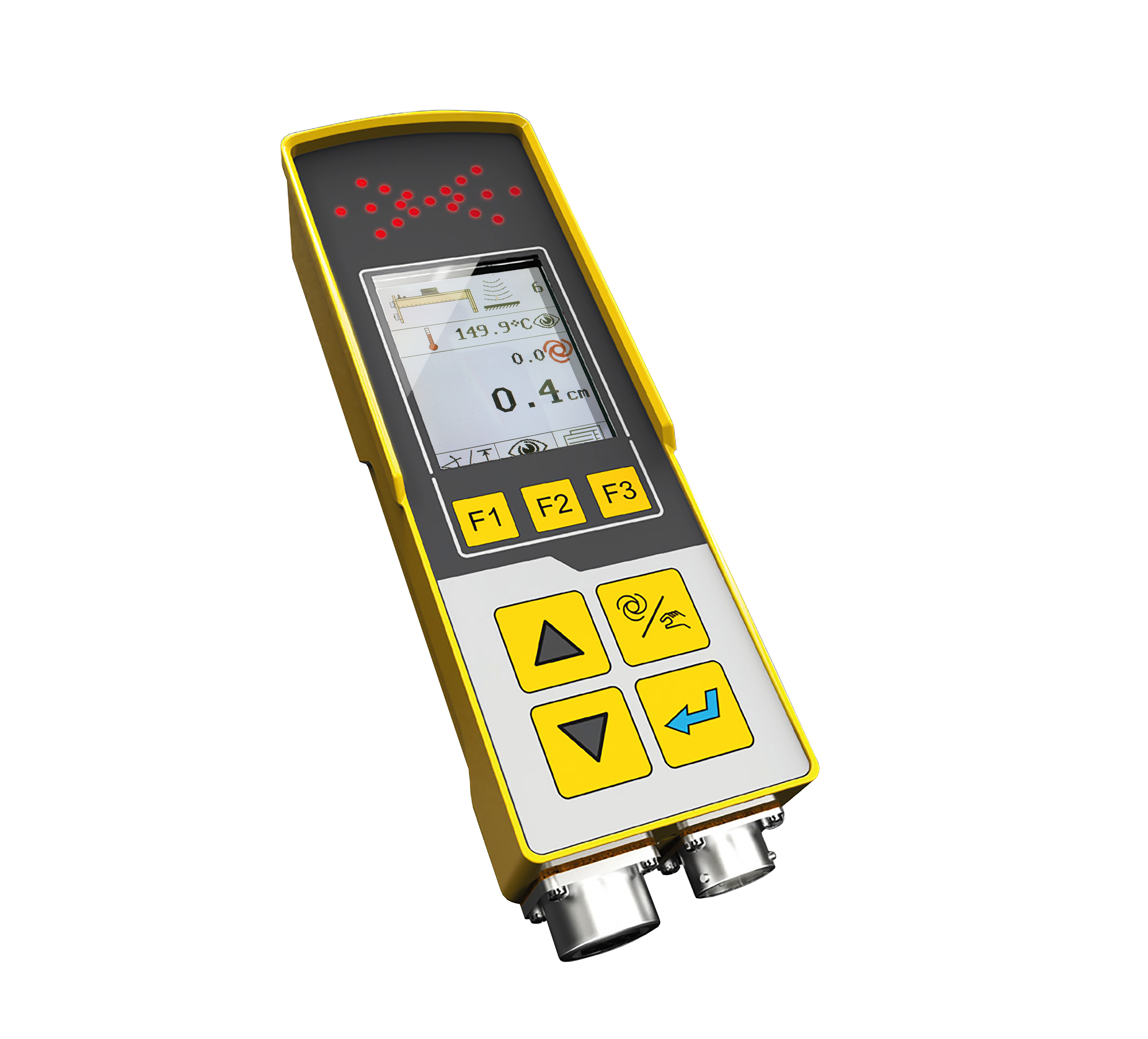 MOBA-matic II levelling controller MOBA-matic II levelling controller |
At first, you must install the system on the paver via the 10pin connector. Immediately after starting the ignition of the paver, the MOBA-matic II levelling controller starts with a displayed power-on message for approx. 4 seconds.
If any of the digital controller’s keys is pressed during this message, the version numbers of the used software appear on the display for approx. 4 seconds.
Then the side detection is displayed for approx. 4 seconds; i.e. a red arrow on the display shows on which machine side the MOBA-matic II is connected.
If the sensor that has been worked with is still connected, the display switches to the working window.
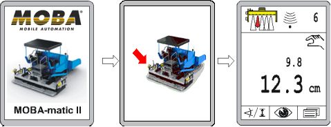
Power on message
Preparatory Actions:• Start the engine and bring the hydraulic pressure up to operating temperature and have the motor run at a high rotation speed (> idle running) |
Hight reference for the start |

Set up:
• Switch MOBA-matic controller with the Auto/manual key into the “Manual” operating mode
• Run cylinder with Up or Down keys into the centre position to have a sufficient lift on both sides
for the Setting
• Enter the parameter menu
• Change with function key F2 to menu “Min. pulse Raise” (Factory setting is 50msec.)
• Change with function key F2 to menu “Min. pulse Lower” (Factory setting is 50msec.)
• Now press Up and Down key at the same time to activate alternating valve triggering
• The raising and lowering hydraulic valves are alternately controlled with the set pulse times.
This is shown by the LED arrow with changing Up and Down
• Press function key F1 for returning to the “Min. pulse Raise” menu item
• Raise the value with the Up key (or possibly with Down) until the cylinder in the upward Motion
is moved by 1 mm per pulse
• Press function key F2 for returning to the “Min. pulse Lower” menu item
• Raise the value with the Up key (or possibly Down) until the upward/downward motion is in balance, this means no longer moves off in one direction. Instead of the upward/downward motion by 1 mm per pulse, the hydraulic design may then result in the cylinder also being motionless
• Terminate the hydraulic control by again simultaneously pressing the Up and Down key or automatically by quitting the Parameters.
Interested in more Information about MOBA-matic II ? Follow the links below:
https://mobacommunity.com/blogs/entry/MOBA-Matic
https://mobacommunity.com/blogs/entry/MOBA-Matic-no-other-system-is-that-flexible
https://mobacommunity.com/blogs/entry/Do-You-Know-the-Advantages-of-the-MOBA-matic-II
https://mobacommunity.com/blogs/entry/Reliable-levelling-system-new-digital-controller-MOBA-matic-II-proves-itself-in-asphalt-paving
https://mobacommunity.com/blogs/entry/MOBA-matic-II-A02-cross-operation