-
Contents
-
Table of Contents
-
Bookmarks
Quick Links
Technical Support
Mobileye 5 – Technical Installation Guide_Rev 0.3
Jan, 2012
Page 1 of 38
Mobileye 5
— Technical Installation Guide —
Mobileye Proprietary and Confidential
support@mobileye.com
Related Manuals for Mobileye Mobileye 5
Summary of Contents for Mobileye Mobileye 5
-
Page 1
Technical Support Mobileye 5 – Technical Installation Guide_Rev 0.3 Jan, 2012 Page 1 of 38 Mobileye 5 — Technical Installation Guide — Mobileye Proprietary and Confidential support@mobileye.com… -
Page 2
Email: support@mobileye.com © 2007-2011 Mobileye Technologies Limited. All rights reserved. Reproduction in whole or in part without written permission is prohibited. Mobileye, Mobileye AWS, Mobileye C2, Mobileye 5 and the Mobileye logo are registered trademarks of Mobileye Technologies Ltd. www.mobileye.com Mobileye Proprietary and Confidential support@mobileye.com… -
Page 3: Table Of Contents
Installation and Safety Instructions …………… 6 Mobileye 5 Description ……………… 7 Mobileye 5 Components overview …………..7 2.1.1 Mobileye 5 Main Unit & connecting cable (CAB000105) ……7 2.1.2 EyeWatch — Display & Control unit (CAB000087) ……..8 2.1.3 External Fuse Holder ……………… 8 2.1.4 3M VHB Surface Cleaner …………….
-
Page 4
Technical Support Mobileye 5 – Technical Installation Guide_Rev 0.3 Jan, 2012 Page 4 of 38 4.3.4 Actual Camera Position …………….29 4.3.5 Signals Source ………………31 4.3.6 Signals polarity Configuration …………..32 4.3.7 Camera Calibration ……………… 32 4.3.8 Signal Test & Configuration …………..35 4.3.9 Test Drive ……………….. -
Page 5: Warnings
Mobileye 5 is not an automated driving system and it does not act as a substitute for any aspect of driver vehicle control or safe driving practices. Drivers are strongly…
-
Page 6: Installation And Safety Instructions
Authorized Mobileye 5 Dealer or Installer. The Mobileye 5 should only be operated with 12VDC~24VDC power. Do not cover or obstruct the Camera Unit or Mobileye 5 Display and Control Unit. Only proper tools are to be used. Only L.E.D voltage tester or Digital Multi Meter should be used.
-
Page 7: Mobileye 5 Description
The Mobileye 5 Main Unit and Connector Cable (Camera) The EyeWatch Display & Control Unit (Optional) When receiving the Mobileye 5 please verify receiving & identify all the following components: 2.1.1 Mobileye 5 Main Unit & connecting cable…
-
Page 8: Eyewatch — Display & Control Unit (Cab000087)
Figure 2: EyeWatch Display and Control Unit with connecting cable 2.1.3 External Fuse Holder The Mobileye 5 is supplied with an External Fuse Holder and a 2A Fuse for protection against short circuiting the vehicle electrical system. Figure 3: External Fuse Holder & 2A Fuse Mobileye Proprietary and Confidential support@mobileye.com…
-
Page 9: Vhb Surface Cleaner
Jan, 2012 Page 9 of 38 2.1.4 3M VHB Surface Cleaner The 3M VHB Surface Cleaner supplied with Mobileye 5 Cleans and degreases the Windshield surface to ensure optimum adhesion for 3M VHB Tape provided with the Mobileye 5 Main Unit.
-
Page 10: Mobileye 5 Connections Description
It is attached to the vehicle’s front windshield with the provided 3M double sided sticker. The Mobileye 5 Connecting cable is split into a few various cables which are used to connect to the vehicle power source, to the vehicle CAN-bus, to the vehicle High- beams (for IHC) and to the Mobileye EyeWatch display and Control unit and Mobileye EyeCAN.
-
Page 11: External Fuse Holder & 2A Fuse
Table 2: EyeWatch connections 2.2.4 EyeCAN – Mobileye CAN to USB interface The EyeCAN is NOT part of the Mobileye 5 system. It is a tool which enables the installer to configure and calibrate the Mobileye 5 system during the installation. The Mobileye 5 EyeCAN Male connector (P2) is used for connection with the Mobileye EyeCAN Box Female connector labeled “CAN”…
-
Page 12: Mobileye 5 Installation
Nominal 5.2W * A 12V vehicle has battery voltage of 13.7V and 24V vehicle has battery voltage of 27V. ** The current consumption of the Mobileye 5 is depended on the vehicle system voltage (12 or 24V). Additional Notes: 1. Mobileye 5 complies with automotive standard (ISO-7637-2) regarding voltage transients for all signals (input voltage and car signals).
-
Page 13: Mobileye 5 Installation Procedure
Technical Support Mobileye 5 – Technical Installation Guide_Rev 0.3 Jan, 2012 Page 13 of 38 3.2 Mobileye 5 Installation Procedure The following chart summarizes the main stages of the Mobileye 5 installation procedure: Mobileye Proprietary and Confidential support@mobileye.com…
-
Page 14: Mobileye 5 Connection Scheme
Page 14 of 38 3.2.1 Mobileye 5 Connection Scheme Please ensure that you identify the Mobileye 5 cables according to diagram below. The paragraphs that follow will present the function of each cable, and then guide you through their actual connection procedures with the car signals.
-
Page 15: Installing The Eyewatch (Optional)
Unit on the rear view mirror or place it on the dashboard before passing the cable behind the vehicle trimmings). 3. Firmly connect the appropriate wire from the Mobileye 5 (CAB000105) to the identified vehicle signal. Each wire in the Mobileye 5 cable mentioned above has a unique color.
-
Page 16: Installing The Mobileye 5 Main Unit (Camera)
Jan, 2012 Page 16 of 38 5. Insert the EyeWatch cable (CAB000087) behind the vehicle the trimmings so that it reaches the EyeWatch connector of the Mobileye 5 cable (CAB000105) WARNINGS! — The EyeWatch and Main Unit should be placed in a location that does not obstruct the driver’s field of view.
-
Page 17
Technical Support Mobileye 5 – Technical Installation Guide_Rev 0.3 Jan, 2012 Page 17 of 38 In tall commercial vehicles that do not have an engine hood occluding the field of view of the camera, the v Main Unit can be placed on the lower part of the windshield, while considering all of the above-mentioned requirements. -
Page 18
Connector 6 pin male 6 pin Female 7. Power On the laptop computer. 8. Power on the Mobileye 5 system by turning on the vehicle ignition switch to ACC (Accessory) position. 9. Run the Mobileye Setup Wizard Application NOTE: Chose the vehicle from the Internal Database in the Mobileye Setup Wizard application before continuing (see Appendix F for more details). -
Page 19
Figure 1-10 Vision Sensor Unit located on the windshield behind the rear view mirror NOTE: At the end of this process, all the system components are connected and all Mobileye 5 components are attached to the vehicle and connected to the Laptop PC Mobileye Proprietary and Confidential… -
Page 20: System Calibration Procedure
— Disconnect the EyeWatch connection — Move the laptop carelessly — Turn off the vehicle or in any other way turn off power to the Mobileye 5 system 4.1 Removing the Mobileye 5 Back Covers In order to calibrate the Mobileye 5, the camera angle must be set prior to the calibration process.
-
Page 21
Technical Support Mobileye 5 – Technical Installation Guide_Rev 0.3 Jan, 2012 Page 21 of 38 2. Once the 2 Brackets on the Left and Right side have been released pull the Lower Back Cover downwards and remove completely. Mobileye Proprietary and Confidential… -
Page 22
Technical Support Mobileye 5 – Technical Installation Guide_Rev 0.3 Jan, 2012 Page 22 of 38 3. Un-screw the 2 small screws on the Left and Right sides to remove the Upper Back Cover. 4. Once the 2 screws have been removed, remove the Upper cover completely. -
Page 23
Technical Support Mobileye 5 – Technical Installation Guide_Rev 0.3 Jan, 2012 Page 23 of 38 5. Now use the Camera adjustment screw to set the correct camera angle by releasing the screw a little and moving the Camera along the Camera Railing. -
Page 24: Adjusting The Camera Angle
Technical Support Mobileye 5 – Technical Installation Guide_Rev 0.3 Jan, 2012 Page 24 of 38 4.2 Adjusting the Camera Angle To adjust the correct camera angle follow the below procedure: 1. Measure the Camera Height from the Ground Up using a measuring tape 2.
-
Page 25
Technical Support Mobileye 5 – Technical Installation Guide_Rev 0.3 Jan, 2012 Page 25 of 38 3. After marking the Camera Height on the TAC Target use the image feed (camera installation slide) to adjust the Camera Lens Angle by sliding it Up/Down the Camera Railing until the Marked Line is in the Desired Camera Height Range. -
Page 26: Mobileye Setup Wizard — Calibration
Mobileye 5 – Technical Installation Guide_Rev 0.3 Jan, 2012 Page 26 of 38 4.3 Mobileye Setup Wizard – Calibration Follow the Mobileye Setup Wizard Instructions to complete the Mobileye 5 Calibration Process. 4.3.1 Local Information In the «Local Information» slide please select the following: a) Select the Country in which the installation is being done.
-
Page 27: Car Information
Technical Support Mobileye 5 – Technical Installation Guide_Rev 0.3 Jan, 2012 Page 27 of 38 4.3.2 Car Information In the “Car Information” Slide, please enter the following: a) Vehicle Chassis num Enter the last 6 digits of the vehicle VIN number.
-
Page 28: Car Hood Step
Technical Support Mobileye 5 – Technical Installation Guide_Rev 0.3 Jan, 2012 Page 28 of 38 4.3.3 Car Hood Step NOTE: Perform car hood calibration only if there is a permanent obstruction to the camera’s field of view by the car hood…
-
Page 29: Actual Camera Position
Technical Support Mobileye 5 – Technical Installation Guide_Rev 0.3 Jan, 2012 Page 29 of 38 4.3.4 Actual Camera Position In the «Actual Camera position» slide set the following: 1. Camera height – Enter the Camera height measured from the Ground Up 2.
-
Page 30
Technical Support Mobileye 5 – Technical Installation Guide_Rev 0.3 Jan, 2012 Page 30 of 38 4.3.4.1 Camera Position Measurements Measure the following dimensions using a measuring tape or any other appropriate measurement tool: Camera Height from the ground: Lateral distance from the camera to the right and left windshield edges: Horizontal distance to the front end (i.e. -
Page 31: Signals Source
— The Signal source slide informs you about the source of each signal. — In Mobileye 5 the Signal Source will always be “CAN” — Mobileye 5 cannot be configured to work with the vehicle’s Analog signals. — CAN-Bus signals cannot be configured back to work with an Analog connection.
-
Page 32: Signals Polarity Configuration
Technical Support Mobileye 5 – Technical Installation Guide_Rev 0.3 Jan, 2012 Page 32 of 38 4.3.6 Signals polarity Configuration When performing a CAN installation this slide is not active (see image 1 below). Click “Next” to continue 4.3.7 Camera Calibration NOTE: Please perform this process while seated in the drivers seat 1.
-
Page 33
Technical Support Mobileye 5 – Technical Installation Guide_Rev 0.3 Jan, 2012 Page 33 of 38 4. When the «Calculate Close TAC» is complete, an image of the close target with red dots will appear. 5. Now locate the TAC Target far from the front of the car (~1.0 m) and click on “Calculate far TAC”. -
Page 34
Technical Support Mobileye 5 – Technical Installation Guide_Rev 0.3 Jan, 2012 Page 34 of 38 7. When the «Calculate far TAC» is complete, you can see the F.O.E (Focus of Expansion) and Camera Height results at the bottom left corner of the slide. -
Page 35: Signal Test & Configuration
Technical Support Mobileye 5 – Technical Installation Guide_Rev 0.3 Jan, 2012 Page 35 of 38 10. When burning has been completed, click ‘Next’. 4.3.8 Signal Test & Configuration In this step you need to click on the «Start Test» button in order for the application to check the signals polarity.
-
Page 36: Test Drive
Technical Support Mobileye 5 – Technical Installation Guide_Rev 0.3 Jan, 2012 Page 36 of 38 Only when all signals are labeled with a Green Check Icon beside them, may you proceed to the next stage. If the Signal Test has been successful, click “Next”…
-
Page 37
Red/White. 4.3.9.2 Checking the speed indication while driving on the road: 1. Compare the speed indication between the Mobileye 5 system speed (as displayed in the laptop screen) to that of the host vehicle indicator. 2. Up to 5 km/h difference is allowed. -
Page 38: Parameter Error Significance And Functionality Implications
Technical Support Mobileye 5 – Technical Installation Guide_Rev 0.3 Jan, 2012 Page 38 of 38 5 Appendix A Parameter error significance and functionality implications Camera height range measurement accuracy system proportional to the camera height error. E.g., 1 cm error in camera height of 2.2 meters implies a ~0.45% error in range…
перейти к содержанию
HEXAGON Mobileye 6 Подмена камеры

Краткое руководство пользователя Mobileye 6
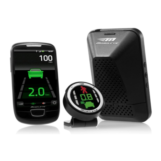
В системе Mobileye 630 (доступен водитель ROS) используется интеллектуальная цифровая камера, расположенная на переднем лобовом стекле внутри автомобиля.
Внутри камеры мощный чип обработки изображений Mobileye EyeQ2® обеспечивает
высокопроизводительная обработка изображений в реальном времени с использованием технологий обнаружения транспортных средств, полос и пешеходов Mobileye для эффективного измерения и расчета динамических расстояний между транспортным средством и дорожными объектами.
Комплектация

Другое необходимое оборудование
- Ноутбук
- Квасер USB/CAN адаптер
- Измерительные инструменты для калибровки (рекомендуется рулетка и уровень)
Установка
- Установите Mobileye в центре лобового стекла.
- Подключите Mobileye к шине CAN автомобиля с помощью основного кабеля Mobileye 6.
- Подключите Eye Watch к основному кабелю.
- Подайте питание 12 В постоянного тока через BAT+ и GND. Требуется сигнал зажигания 12 В.
- Подключите ноутбук с Windows к Mobileye через адаптер USB Eye CAN.

Коммуникации — Мастер настройки (конфигурация и калибровка)
- Загрузите установщик мастера установки здесь: mobileye.com/us/fleets/support
- Несмотря на то, что Mobileye необходимо настроить и откалибровать с помощью адаптера Eye CAN, пользователь может соединить Eye CAN и завершить его, чтобы адаптировать его к собственному интерфейсу шины CAN.


Коммуникации — драйвер ROS (регистрация и визуализация)
- РОС: wiki.ros.org
- Драйвер Mobileye ROS: Automotivetuff.atlassian.net/wiki/spaces/RW
Дополнительная информация
- Autonomoustuff.com
- Полная документация
Документы / Ресурсы

Руководство пользователя
Важная информация по безопасности
ПЕРЕД ИСПОЛЬЗОВАНИЕМ СИСТЕМЫ MOBILEYE 5-SERIES ВНИМАТЕЛЬНО ОЗНАКОМЬТЕСЬ С ПРАВИЛАМИ БЕЗОПАСНО-
СТИ И ПРЕДУПРЕЖДЕНИЯМИ, СОДЕРЖАЩИМИСЯ В НАСТОЯЩЕМ РУКОВОДСТВЕ ПОЛЬЗОВАТЕЛЯ.
ПРЕДУПРЕЖДЕНИЯ! ИСПОЛЬЗОВАНИЕ СИСТЕМ MOBILEYE 5-SERIES НЕ ОТМЕНЯЕТ СОБЛЮДЕНИЯ ПРАВИЛ БЕЗОПАС-
НОГО И ВНИМАТЕЛЬНОГО ПОВЕДЕНИЯ НА ДОРОГЕ.
ЗАПРЕЩАЕТСЯ ИЗМЕНЯТЬ НАСТРОЙКИ СИСТЕМЫ MOBILEYE 5-SERIES ВО ВРЕМЯ ДВИЖЕНИЯ!
Не нажимайте никакие кнопки системы Mobileye 5-Series, прежде чем вы изучите их назначение. Устанавливая
Усовершенствованные системы помощи водителю Mobileye 5-Series, вы соглашаетесь эксплуатировать системы
Mobileye 5-Series в соответствии с Правилами безопасности и предупреждениями, приведенными ниже. Если вы не
согласны с настоящими условиями, верните изделие Mobileye 5-Series дилеру в оригинальной упаковке в течение
30 дней с момента покупки и получите полный возврат стоимости.
Системы Mobileye 5-Series – Усовершенствованные системы помощи водителю, которые предупреждают водителя о
некоторых потенциально опасных ситуациях. При использовании систем водитель должен самостоятельно выпол-
нять все задачи управления транспортным средством, внимательно следить за всеми условиями движения, следовать
всем рекомендациям по безопасному управлению автомобилем, а также соблюдать правила дорожного движения.
Системы Mobileye 5-Series не являются системами автоматического вождения: водитель должен сохранять полный
контроль над транспортным средством и соблюдать рекомендации по безопасному управлению автомобилем. Води-
тели должны знать, что системы Mobileye 5-Series никоим образом не отменяет необходимость соблюдения должной
осторожности, которая обеспечивает безопасную и безаварийную езду на автомобиле.
Несмотря на то что Mobileye 5-Series является новейшей разработкой в области компьютеризированного видения и
других технологий, Mobileye не может гарантировать и не гарантирует 100% точности обнаружения транспортных
средств, пешеходов, дорожных знаков или полос движения и не гарантирует предоставления любых связанных с этим
звуковых и визуальных предупреждающих сигналов. Кроме того, на качество распознавания и реагирования систем
Mobileye 5-Series могут отрицательно влиять дорожные, погодные и иные условия.
Соответственно, для обеспечения безопасности на дороге водители должны как и прежде соблюдать рекомендации
по безопасному управлению автомобилем, а не полагаться в этом на Mobileye 5-Series.
Водители должны проявлять осторожность при использовании дисплея Mobileye 5-Series (входит в состав некоторых
моделей Mobileye 5). Постоянно контролируйте ситуацию на дороге, в том числе во время сверки с дисплеем Mobileye
5-Series.
Для обеспечения точности информации, приведенной в настоящем Руководстве пользователя, при-
няты все возможные меры. Тем не менее, компания Mobileye Technologies Limited не предоставляет ни-
каких явных или подразумеваемых гарантий или заверений, основанных на прилагаемой информации.
Компания Mobileye Technologies Limited оставляет за собой право изменять технические характеристики и описания
оборудования в данной публикации без предварительного уведомления. Сведения о любых ошибках или упущениях
могут быть переданы в Службу технической поддержки компании Mobileye Technologies Limited.
Электронная почта: support@mobileye.com
Инструкции по установке и техника безопасности
Монтаж системы Mobileye 5-Series должен выполняться официальным дилером Mobileye или специалистом по
монтажу.
Перенос системы Mobileye 5-Series с одного транспортного средства на другое должен выполняться только
официальным дилером Mobileye или специалистом по монтажу.
В качестве источника питания системы Mobileye 5-Series следует использовать только источник питания мощно-
стью 12~24 В постоянного тока.
Не закрывайте и не заграждайте камеру или видеоконтрольное устройство Mobileye 5-Series.
Не используйте систему Mobileye 5-Series для любых других целей, кроме описанных в настоящем Руководстве
пользователя.
Кнопки камеры
Включение/выключение систем Mobileye 5-Series
Нажмите и удерживайте на камере (o) центральную кнопку.
Регулирование громкости
Для уменьшения громкости несколько раз нажмите кнопку (–); для увеличения громкости не-
сколько раз нажмите кнопку (+). Предусмотрено 6 уровней громкости (0-5). Примечание: При
установке значения громкости на «0», звуковые сигналы систем Mobileye LDW и Mobileye HMW
блокируются, но громкость звуковых сигналов FCW устанавливается в значение по умолчанию
– «3».
Панель управления
Обратите внимание, что во время движения автомобиля на любой скорости выше
0 км/ч кнопка меню EyeWatch будет отключена, чтобы предотвратить изменение настроек
системы во время движения.
Настройки громкости всегда включены, независимо от скорости автомобиля.
Выбор режима
Включение/выключение системы Mobileye 560
Выключение: Нажмите кнопку (
Включение: Нажмите любую кнопку.
Изменение уровня яркости дисплея EyeWatch:
a. Нажмите (
b. При помощи кнопок (–) (+) уменьшите или увеличьте уровень яркости.
c. Доступно 5 уровней (1–5). Mobileye 560 автоматически регулирует уровень яркости для
дня и ночи.
Изменение времени срабатывания предупреждения об опасном сближении:
a. Нажмите (
b. Чтобы уменьшить время предупреждения об опасном сближении с впереди идущим
автомобилем, нажмите (–), а чтобы увеличить, нажмите (+).
c. Доступные уровни: 0.1-2.5
Изменение чувствительности LDW:
a. Нажмите (
b. Чтобы уменьшить чувствительность Mobileye LDW, нажмите (–), а чтобы увеличить, на-
жмите (+).
c. Доступно 3 уровня (0-2).
ВНИМАНИЕ:
1.
Установка чувствительности Mobileye LDW на «0» приведет к отключению оповещений LDW.
2.
Чтобы включить оповещения Mobileye LDW, убедитесь, что чувствительность Mobileye LDW
установлена на уровне 1 или 2.
(входит в комплект системы Mobileye 560)
) до отключения дисплея EyeWatch.
) один раз. На дисплее появятся все пиктограммы.
) дважды. Появится красная пиктограмма.
) 3 раза. Появятся пиктограммы правой и левой полос движения.

Комментарии
9
Войдите или зарегистрируйтесь, чтобы писать комментарии, задавать вопросы и участвовать в обсуждении.

Купили машину из Японии, с установленной системой. Если честно, я пока не ощутила от неё особой пользы при движении в городе

У нас мобилай ставят на все новые машины. У меня такая стоит. В страховке годовой большая скидка если она установлена. Реально она очень помогает. Кстати наша Израильская разработка которую продали неделю назад Интелю за 15 млрд $

Согласен, хорошая штука))

Тех осмотр с такой херней не пройдешь, да как вообще ездить можно, загараживает весь обзор!
Обзору она не мешает вообще! Мешает только регик — буду переставлять! Это во первых. Во вторых установить её можно в любое другое место, хочешь справа хочешь слева! А в третьих с техосмотром я не парюсь все делается легко и просто!  да и почему не проедешь?

да она сама создаёт аварийную ситуацию закрывая столько обзора по центру ))
Обзору она не мешает. И установить можно в любое место как тебе удобно! Мешает только регик!

Задумка прикольная, но на наших дорогах она с ума сойдет 
Разметки у нас нет в принципе.
Впереди идущие машины едут раком, боком и наперекосяк и т.д.
Хотя идея прикольная
Спасиб. Пока не сходит и работает чётко. Разметка к сожалению у нас страдает — это да, не поспоришь… каждое оповещение программируется и настраивается индивидуально!