- Manuals
- Brands
- MotorGuide Manuals
- Outboard Motor
- Xi3 Wireless Edition
- Operation, maintenance & installation manual
-
Contents
-
Table of Contents
-
Troubleshooting
-
Bookmarks
Quick Links
Operation
Maintenance
Installation
Warranty
Manual
Related Manuals for MotorGuide Xi3 Wireless Edition
Summary of Contents for MotorGuide Xi3 Wireless Edition
-
Page 1
Operation Maintenance Installation Warranty Manual… -
Page 3
Hereby, Attwood Corporation declares that the radio equipment type, Xi3 Trolling Motor System, is in compliance with Directive 2014/53/EU. – The full text of the EU declaration of conformity is available at the following internet address: http://www.motorguide.com/support/literature Important Operator Information ISO 7000‑0434B ‑ Caution symbol Consult this documentation in all cases where this symbol appears. -
Page 4
Warranty Message The product you have purchased comes with a Limited Warranty from MotorGuide. The terms of the policy are set forth in the Warranty Information section of this manual. The policy statement contains a description of the duration of coverage, important disclaimers and limitations of damages, and other related information. -
Page 5: Table Of Contents
Warranty Information MotorGuide Two Year Limited Warranty…………1 General Information and Component Identification Component Identification………………4 Recording the Serial Number…………….5 Product Registration………………. 5 Boater’s Responsibilities………………5 Protecting People in the Water…………….6 Passenger Safety Message…………….6 Safe Boating Suggestions……………… 6 Product Installation, Wiring, and Battery Information Installing the Trolling Motor……………..
-
Page 6
Maintenance and Storage Trolling Motor Care………………. 27 Inspection and Maintenance Schedule…………. 27 Storage Preparation………………29 Battery Inspection………………… 29 Corrosion Control Anode (Saltwater Models)……….. 29 Propeller Replacement………………30 Owner Service Assistance Troubleshooting………………..33 Troubleshooting the Handheld Remote…………36 Service Assistance………………. 38 Mercury Marine Service Offices……………. -
Page 7: Warranty Information
3. MotorGuide, at its discretion, will repair or replace items covered under the terms of this warranty. Neither MotorGuide nor MotorGuide service…
-
Page 8
Non‑serialized «Service‑Repair» electric trolling motors are NOT warranted. «Service‑Repair» motor denotes a trolling motor sold by MotorGuide that may be used, but has been inspected and may have had minor repairs. Original retail purchaser of a «Service‑Repair» motor is the first purchaser of the motor after it is denoted as «Service‑Repair.»… -
Page 9
WARRANTY INFORMATION 12. ALL INCIDENTAL OR CONSEQUENTIAL DAMAGES ARE EXCLUDED FROM THIS WARRANTY, WARRANTIES OF MERCHANTABILITY AND FITNESS ARE EXCLUDED FROM THIS WARRANTY, IMPLIED WARRANTIES ARE LIMITED TO THE LIFE OF THIS WARRANTY. SOME STATES DO NOT ALLOW LIMITATIONS ON HOW LONG AN IMPLIED WARRANTY LASTS OR THE EXCLUSION OR LIMITATION OF INCIDENTAL OR CONSEQUENTIAL DAMAGES, SO THE ABOVE LIMITATIONS OR EXCLUSIONS MAY NOT APPLY TO YOU. -
Page 10: General Information And Component Identification
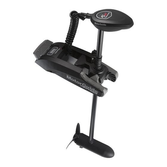
GENERAL INFORMATION AND COMPONENT IDENTIFICATION Component Identification Head Curly cable Foot release lever Battery cables (hidden) Handheld wireless remote Deck mount Propeller Skeg Lower unit (motor) Depth collar Depth collar knob Composite column Steering transmission 64267…
-
Page 11: Recording The Serial Number
Model identification number Serial number 64677 Product Registration For warranty purposes, please register your MotorGuide trolling motor by completing the enclosed warranty card or by visiting www.motorguide.com. Boater’s Responsibilities The operator (driver) is responsible for the correct and safe operation of the boat and safety of its occupants and general public.
-
Page 12: Protecting People In The Water
GENERAL INFORMATION AND COMPONENT IDENTIFICATION Protecting People in the Water WHILE YOU ARE TROLLING It is difficult for a person in the water to take quick action to avoid a boat heading in their direction, even at slow speeds. 21604 Always slow down and exercise extreme caution any time you are boating in an area where there might be people in the water.
-
Page 13
GENERAL INFORMATION AND COMPONENT IDENTIFICATION Passenger boarding. Stop the trolling motor whenever passengers are boarding or unloading. Be alert. The operator of the boat is responsible by law to maintain a proper lookout by sight and hearing. The operator must have an unobstructed view particularly to the front. -
Page 14: Product Installation, Wiring, And Battery Information
Locating tabs Side panel screw 2. If you are replacing an existing MotorGuide or competitive brand trolling motor on your current boat, check if the existing mounting holes align with the new deck mount before drilling new holes. Ensure that the mounting location meets the requirements listed in Step 4.
-
Page 15
PRODUCT INSTALLATION, WIRING, AND BATTERY INFORMATION IMPORTANT: A minimum clearance of 13 mm (0.5 in.) is required between the motor column and the rub rail on the boat when the trolling motor is deployed. 53447 5. Place the trolling motor onto the deck of the boat at the selected location in the stowed position. -
Page 16
PRODUCT INSTALLATION, WIRING, AND BATTERY INFORMATION NOTE: If the trolling motor is being mounted to a carpeted boat deck, the rubber isolators are not required. 52406 Deck mounting bracket Mounting bolt Rubber isolator Deck Washer Stainless steel nylock nut Carpet 8. -
Page 17: Recommended Practice And Procedures
• Install a manual reset circuit breaker in line with the trolling motor positive leads within 1.8 m (6 ft) of the batteries. These can be purchased from your local MotorGuide retailer or from www.motorguide.com.
-
Page 18: Battery Precautions
INFORMATION • Do not extend the included 10‑gauge battery cables more than 1.8 m (6 ft) for a total of 3 m (10 ft). If longer battery cables are required, MotorGuide offers accessory 8 mm² (8‑gauge) battery cables. • Use stainless steel nylock nuts to secure the battery cables to their terminals.
-
Page 19: Wire Color Code Abbreviations
PRODUCT INSTALLATION, WIRING, AND BATTERY INFORMATION Wire Color Code Abbreviations Wire Color Abbreviations Black Blue Brown GRY or GRA Gray Green ORN or ORG Orange Pink PPL or PUR Purple White Yellow LT or LIT Light DK or DRK Dark Battery Connection WARNING Before working around electrical system components, disconnect the battery…
-
Page 20
PRODUCT INSTALLATION, WIRING, AND BATTERY INFORMATION 3. Connect the negative (–) trolling motor lead to the negative (–) trolling motor battery terminal. 12–volt battery connection Power cables to trolling motor Manual reset circuit breaker Trolling motor battery 64893 24-VOLT BATTERY CONNECTION 1. -
Page 21: Wire And Cable Routing
PRODUCT INSTALLATION, WIRING, AND BATTERY INFORMATION 5. Starting with the positive (+) lead, reconnect the battery cables to the engine starting or accessory battery. BLACK Battery A Battery B 37824 24-volt battery connection Power cables to trolling motor Manual reset circuit breaker Jumper wire (not supplied) Negative (–) battery terminal Wire and Cable Routing…
-
Page 22: Connecting The Sonar Display To The Trolling Motor
This sonar display connection procedure applies to trolling motor models with internal sonar that offer built‑in 200/83 kHz sonar transducers compatible with Eagle®, Garmin™, Humminbird™, Lowrance™, and Vexilar® brand sonar displays. For compatibility with other sonar units, refer to www.motorguide.com.
-
Page 23: Reducing Sonar Transducer Interference
Harness—to nose cone sonar Lowrance 7‑pin plug— to sonar display 64685 Transducer Adapter Cables Available from MotorGuide Lowrance 7‑to‑6‑pin adapter Vexilar 3‑pin adapter Garmin 6‑pin adapter Humminbird 7‑pin adapter Reducing Sonar Transducer Interference The following items should be checked, in order, to help improve sonar performance.
-
Page 24
PRODUCT INSTALLATION, WIRING, AND BATTERY INFORMATION a. Ethernet links b. Multiple sonar transducers operating on same frequencies c. Other 3rd party electronic equipment 6. Ferrite rings/chokes may have some positive effect on sonar performance. Ensure you have the correct size for the gauge wire you are installing on. -
Page 25: Trolling Motor Operation
TROLLING MOTOR OPERATION Status Indicator Light Identification This trolling motor is equipped with a multifunction status indicator light panel. It can display the on/off status of the motor, propeller, battery charge, and GPS status for quick and easy reference during operation. 64899 Power on/off/sleep indicator light Propeller on/off indicator light…
-
Page 26
TROLLING MOTOR OPERATION 3. Press down on the foot release lever with one hand or foot. While pressing down on the foot release lever, pull and tilt the trolling motor towards the mount. Foot release lever 64686… -
Page 27
TROLLING MOTOR OPERATION 4. Raise the motor out of the water and rotate the transmission so the lower unit is aligned with the mount cradle. Orient the lower unit so the cable does not wrap around the trolling motor column. Slide the lower unit into the mount cradle until the lower unit is fully seated. -
Page 28
TROLLING MOTOR OPERATION IMPORTANT: Optional column mount stabilizers are available for supporting the trolling motor column in extremely rough boating conditions. Recommended MotorGuide Accessory Description ® Standard Ram mount stabilizer ® Long Ram mount stabilizer DEPLOYING THE TROLLING MOTOR 1. Loosen the depth collar knob, then slide the depth collar away from the steering transmission. -
Page 29: Adjusting The Motor Depth
TROLLING MOTOR OPERATION 4. Tilt the motor out of the stowed position and lower the trolling motor until the depth collar rests on top of the steering housing collar. Rotate the trolling motor so the depth collar locks into position on the steering housing collar.
-
Page 30
TROLLING MOTOR OPERATION IMPORTANT: Do not use the curly cable as a handle when raising or lowering the motor. When adjusting the motor depth, ensure that the lower unit is fully submerged a minimum of 30 cm (12 in.) to avoid propeller ventilation. Optimal depth of the lower unit will vary depending on the boat type, water conditions, and the underwater terrain. -
Page 31: Handheld Remote Operation
TROLLING MOTOR OPERATION Handheld Remote Operation WARNING Rotating propellers can cause serious injury or death. Never start or operate the motor out of water. To operate the trolling motor using the handheld remote, sync the foot pedal to the trolling motor receiver. Refer to Activating the Handheld Remote in the Product Installation, Wiring, and Battery Information section of this manual.
-
Page 32
TROLLING MOTOR OPERATION • The Sleep Mode state can start when the trolling motor is in the stowed or deployed position. • Wake the trolling motor from Sleep Mode by pressing any button on the FOB or wireless foot pedal (sold separately). •… -
Page 33: Maintenance And Storage
Record all maintenance performed and save maintenance work orders and receipts. SELECTING REPLACEMENT PARTS Use only original MotorGuide replacement parts. Inspection and Maintenance Schedule BEFORE EACH USE • Inspect for loose or corroded wiring connections.
-
Page 34
MAINTENANCE AND STORAGE NOTE: 2‑4‑C with PTFE is a marine grease available at marine supply stores and your MotorGuide dealer. Tube Ref Description Where Used Part No. 2-4-C with PTFE Depth collar knob screw threads 92-802859A 1 2. Remove the side panels by removing the screw on each side of the mount. -
Page 35: Storage Preparation
MAINTENANCE AND STORAGE Storage Preparation The major consideration in preparing your trolling motor for storage is to protect it from corrosion and damage caused by freezing of trapped water. It is also recommended that batteries are disconnected prior to storage and that the batteries are stored indoors in a dry location during long‑term storage.
-
Page 36: Propeller Replacement
MAINTENANCE AND STORAGE IMPORTANT: Do not paint the anode or clean it with steel wool, sandpaper, wire brushes, or other abrasive materials. Replace the anode if it is more than 50% eroded. Propeller Anode (saltwater models only) Washer Propeller nut 62099 Propeller Replacement WARNING…
-
Page 37
MAINTENANCE AND STORAGE NOTE: Replace the propeller pin if it is bent. 53442 57326 INSTALLING THE PROPELLER 1. Rotate the motor shaft to insert the propeller pin horizontally. Propeller pin 44664 2. Install the propeller onto the motor shaft by engaging the propeller onto the propeller pin. -
Page 38
MAINTENANCE AND STORAGE IMPORTANT: Do not overtighten the propeller nut, or damage to the propeller or propeller pin may occur. Saltwater model shown Propeller Anode (saltwater models only) Washer Propeller nut 62099… -
Page 39: Owner Service Assistance
OWNER SERVICE ASSISTANCE Troubleshooting NOTE: For service information, contact any certified MotorGuide service center. For a full listing of MotorGuide service centers, go to www.motorguide.com or contact any Mercury Marine service office. Symptom Possible Cause Resolution Check the battery charge indicator Weak trolling motor on the trolling motor.
-
Page 40
OWNER SERVICE ASSISTANCE Symptom Possible Cause Resolution Propeller is loose, damaged, or Refer to Propeller Replacement. off‑balance Damaged bearings Contact a Service Center. or bushings Excessive noise or Turn off the power and manually vibration rotate the propeller. If the propeller Magnets interfering does not rotate freely with a slight with armature… -
Page 41
OWNER SERVICE ASSISTANCE Symptom Possible Cause Resolution Check the battery charge indicator Weak trolling motor on the trolling motor. Recharge or batteries replace the battery as required. Batteries in the foot Refer to Troubleshooting the pedal or handheld Foot Pedal and Handheld remote need Remote. -
Page 42: Troubleshooting The Handheld Remote
OWNER SERVICE ASSISTANCE Symptom Possible Cause Resolution Hold one blade and lightly tap the opposite blade with a rubber mallet. Bent propeller pin Difficulty removing Use a putty knife on both sides of propeller the propeller to apply equal pressure. Bent armature Contact a Service Center.
-
Page 43
OWNER SERVICE ASSISTANCE 1. Remove the four screws from the back of the handheld remote. Remove the back cover. Screws (4) 51837 2. Remove the old battery from the battery holder. 51838 3. Insert the new battery with the positive (+) side facing the positive (+) end of the battery holder. -
Page 44: Service Assistance
Your satisfaction with your product is very important to us. If you have a problem or question about your motor, contact your dealer or any certified MotorGuide Service Center. For more service assistance information, refer to Warranty Information. The following information will be needed by the service office: •…
-
Page 45
OWNER SERVICE ASSISTANCE Australia, Pacific Telephone +61 3 9791 5822 Brunswick Asia Pacific Group 41–71 Bessemer Drive Dandenong South, Victoria 3175 +61 3 9706 7228 Australia Europe, Middle East, Africa Telephone +32 87 32 32 11 Brunswick Marine Europe Parc Industriel de Petit-Rechain B-4800 Verviers, +32 87 31 19 65 Belgium…
Калибровка угла установки:
ВАЖНАЯ ИНФОРМАЦИЯ: Эта калибровка является обязательной и выполняется сразу после установки электромотора Motorguide серии Xi на судно. Её следует повторять при перестановке электромотора с одного судна на другое. Эту калибровку можно выполнять, когда судно находится на воде или на суше.
Для выполнения калибровки угла установки требуется фиксированное положение GPS:
- При включении питания электромотор подает одиночный звуковой сигнал.
- После получения фиксированного положения GPS электромотор подает тройной звуковой сигнал, а световой индикатор состояния GPS загорается.
1. Включите питание и запустите электромотор. Отрегулируйте высоту двигателя, чтобы при повороте двигателю не мешали никакие препятствия;
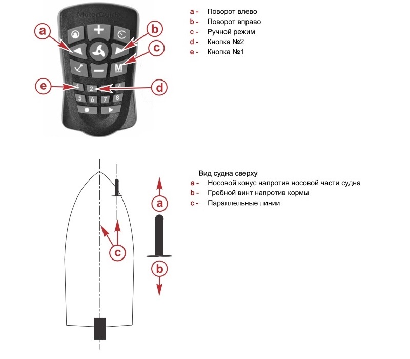
2. Используйте кнопки поворота влево и поворота вправо для поворота блока таким образом, чтобы он был направлен точно вперед, параллельно килю судна, носовой конус нижнего блока был направлен вперед, а гребной винт — к корме;
3. Когда положение нижнего блока будет максимально близко к параллельному с килем, нажмите и удерживайте кнопку ручного режима «M«, затем последовательно нажмите кнопки 1, 1, 2, после этого отпустите кнопку ручного режима «M«. Двигатель малого хода подаст звуковой сигнал, замигает световой индикатор состояния, а затем произойдет возврат в ручной режим. Калибровка угла установки будет завершена.
Калибровка компаса:
ВАЖНАЯ ИНФОРМАЦИЯ: Эта калибровка должна выполняться ДВА РАЗА ПОДРЯД в следующих случаях:
1) после установки электромотора Motorguide серии Xi на судно;
2) если Вы переехали на большое расстояние от места последней калибровки;
3) если система PinPoint GPS не отвечает должным образом.
Эту калибровку можно выполнять, когда судно находится на воде или на суше.
Для выполнения калибровки компаса требуется фиксированное положение GPS:
- При включении питания электромотор подает одиночный звуковой сигнал;
- После получения фиксированного положения GPS электромотор подает тройной звуковой сигнал, а световой индикатор состояния GPS загорается.
1. Выберите подходящую область свободную от препятствий на суше или воде;
2. Разложите электромотор в рабочее положение;
3. Дождитесь получения фиксированного положения GPS;
4. Нажмите и удерживайте кнопку ручного режима «M«, затем последовательно нажмите кнопки 1, 1, 1, после этого отпустите кнопку ручного режима «M«. Электромотор издаст три звуковых сигнала и индикатор состояния сигнала GPS погаснет;
5.1. Если Вы выполняете калибровку компаса на воде: Вам необходимо начать круговое движение медленно сделав два полных круга используя основной двигатель (подвесной, стационарный, бензиновый, дизельный);
5.2. Если Вы выполняете калибровку компаса на суше с судном на прицепе: Вам необходимо во время буксировки прицепа с лодкой начать круговое движение сделав два полных круга;
6. Перед завершением движения по второму кругу электромотор издаст два звуковых сигнала, после полного завершения движения по второму кругу загорится индикатор фиксированного положения GPS и электромотор издаст звуковой сигнал. Процедура калибровки компаса будет завершена.

Особенности модели MotorGuide Xi3:
- Модели Xi3 поставляются с портативным беспроводным пультом управления (Педаль foot pedal доступна как опция)
- Функция SecureStep быстрого и безопасного приведения мотора в рабочее положение
- Тщательные испытания подвердили, что Xi3 самый тихий мотор в своем классе (уровень шума до 40% ниже, чем у конкуретнов)
- Совместимость с системой Pinpoint® GPS и возможность подключения приборов Lowrance
- Композитная штанга с пожизненной гарантией
- Надежная опора из анодированного алюминия
- Коррозионная стойкость. Электроника герметизирована
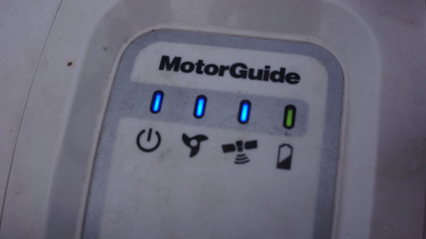
- Индикация на цифровом табло
Ниже опубликован каталог, который вы можете изучить или скачать во вложении к данной статье.
[shortcode_document url=»https://fish.team/images/docs/motorguide_xi3.pdf»]
Комментарии пользователя
Комментариев пользователя на эту запись не создано.
Лодочный электромотор MotorGuide — самая полная инструкция: установка, подключение, обзор, калибровка

Запись опубликована
protmaks · 16 сентября 2020
1 566 просмотров
Самый полезный тюнинг рыболовной лодки — Лодочный электромотор MotorGuide. Без него уже невозможно представить рыбалку, пожалуй, это самый лучший помощник на рыбалке и соревнованиях. Сняли самую подробную инструкцию по моторгайду.
1. Что такое MotorGuide и зачем он нужен? основные плюсы
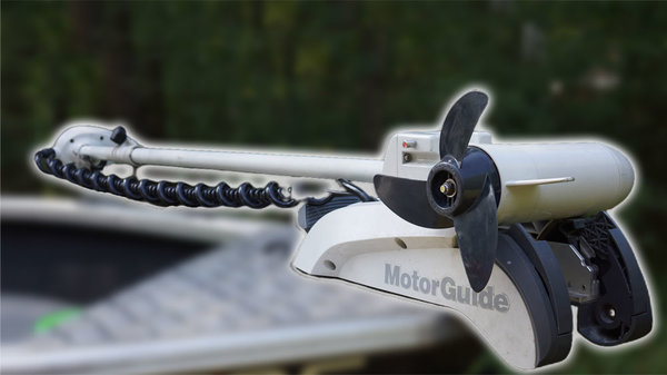
MotorGuide – это бесшумные электромоторы, удобные, легкие и тяговитые, экологически чистые и разрешенные на любых водоемах устанавливаются практически на любом судне.
Зачем же он нужен? Основная его функция – это быстрый якорь, вам не нужно сматывать и разматывать верёвку, особенно это удобно в холодное время года. Также он незаменим на соревнованиях, где время играет решающую роль. Бросив обычный якорь в воду можно распугать рыбу. Также если у вас клюнул трофей, то нажатием одной кнопки можно быстро сняться с якоря и подойти ближе. На электромоторе можно бесшумно передвигаться и облавливать перспективные места на мелководье не пугая рыбу. Ах да, и самое важная и популярная функция, им можно троллить с одинаковой скоростью, а серии Xi5 подключаются к эхолоту при помощи сети nmea 2000 и можно строить маршруты передвижения.
2. Установка MotorGuide на лодку пвх или катер
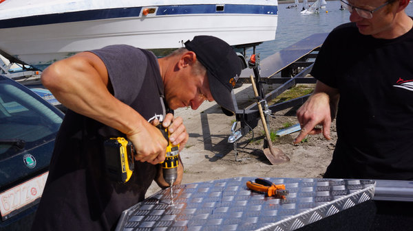
Данные типы моторов можно установить, как на обычную ПВХ лодку, закрепив специальную платформу, так и на многоместный рыболовный катер. Тут всё просто, крепим на болты в горизонтальном положении и направляем его в сложенном виде так, чтобы он не мешал в лодке, но и не торчал из неё.
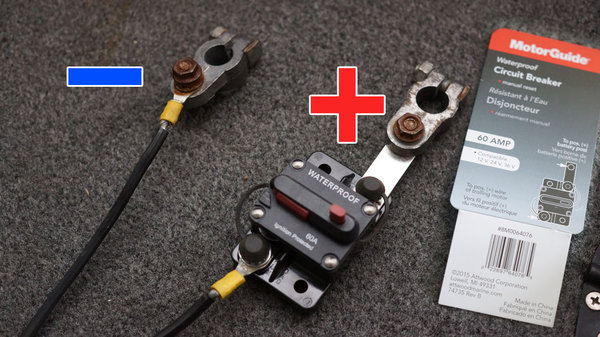
3. Подключение питания и установка предохранителя MotorGuide
У данного электромотора есть два провода, один для подключения сети nmea 2000, а второй – питание. Казалось бы, что может быть проще? Подключил два провода к аккумулятору и всё готово, но нет, есть пару небольших, но очень важных нюансов. Для того, чтобы мотор прослужил у вас долго, необходимо установить предохранитель на 60А или размыкатель с ручным возвратом, как его ещё могут называть. Установить можно двумя способами.
Разрезать плюсовой, красный провод, вставить на разрыв цепи предохранитель и закрепить на стенке рундука. И второй способ, который мы использовали – закрепить его на клемме. Данная мелочь позволит вам избежать возможные поломки и спасёт вас от лишних денежных затрат при коротком замыкании. Также этот предохранитель может служить своеобразным выключателем.
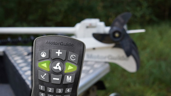
4. Включение и синхронизация, настройка пульта MotorGuide
После установки мотора на лодку и при нажатии кнопок пульта, мотор может не реагировать, необходимо синхронизировать их.
- При включении питания электромотор подает одиночный звуковой сигнал.
- После получения фиксированного положения GPS электромотор подает тройной звуковой сигнал, а световой индикатор состояния GPS загорается.
- Зажмите одновременно две кнопки поворота влево – «<» и вправо – «>» и подержите 10 секунд, до того момента, пока электромотор не издаст характерный звуковой сигнал.
- Если же у вас не получилось это сделать с первого раза, отключите питание и сложите его. Затем включите питание, разложите и повторите предыдущий пункт.
5. Калибровка угла установки MotorGuide
ВАЖНО: Эта калибровка является обязательной и выполняется сразу после установки электромотора MotorGuide серии Xi на судно. Её следует повторять при перестановке электромотора с одного судна на другое. Эту калибровку можно выполнять, когда судно находится на воде или на суше.
Данную калибровку необходимо делать после покупки, либо, когда мотор закручивает провода вокруг себя.
Для выполнения калибровки угла установки требуется фиксированное положение GPS:
- При включении питания электромотор подает одиночный звуковой сигнал.
- После получения фиксированного положения GPS электромотор подает тройной звуковой сигнал, а световой индикатор состояния GPS загорается.
- Включите питание и запустите электромотор. Отрегулируйте высоту двигателя, чтобы при повороте двигателю не мешали никакие препятствия;
- Используйте кнопки поворота влево – «<» и поворота вправо – «>» для поворота блока таким образом, чтобы он был направлен точно вперед, параллельно килю судна, носовой конус нижнего блока был направлен вперед, а гребной винт — к корме;
- Когда положение нижнего блока будет максимально близко к параллельному с килем, нажмите и удерживайте кнопку ручного режима – «M», затем нажмите и отпустите кнопки «1», «1», затем «2». Двигатель малого хода подаст звуковой сигнал, замигает световой индикатор состояния, а затем произойдет возврат в ручной режим. Калибровка угла установки будет завершена.
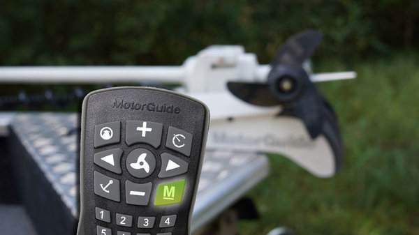
6. Калибровка компаса GPS MotorGuide
ВАЖНО: Эта калибровка выполняется на заводе, НО также должна выполняться в следующих случаях:
- после установки электромотора Motorguide серии Xi на судно;
- если Вы переехали на большое расстояние от места последней калибровки;
- если система PinPoint GPS не отвечает должным образом.
Эту калибровку можно выполнять, когда судно находится на воде или на суше.
Для выполнения калибровки компаса требуется фиксированное положение GPS:
- При включении питания электромотор подает одиночный звуковой сигнал;
- После получения фиксированного положения GPS электромотор подает тройной звуковой сигнал, а световой индикатор состояния GPS загорается.
- Выберите подходящую область свободную от препятствий на суше или воде;
- Разложите электромотор в рабочее положение;
- Дождитесь получения фиксированного положения GPS;
- Нажмите и удерживайте кнопку ручного режима – «М», затем нажмите и отпустите кнопки «1», «1», затем «1», электромотор издаст три звуковых сигнала и индикатор состояния сигнала GPS погаснет;
- Если Вы выполняете калибровку компаса на воде: Вам необходимо начать круговое движение медленно сделав два полных круга используя основной двигатель (подвесной, стационарный, бензиновый, дизельный);
- Если Вы выполняете калибровку компаса на суше с судном на прицепе: Вам необходимо во время буксировки прицепа с лодкой начать круговое движение сделав два полных круга;
- Перед завершением движения по второму кругу электромотор издаст два звуковых сигнала, после полного завершения движения по второму кругу загорится индикатор фиксированного положения GPS и электромотор издаст звуковой сигнал. Процедура калибровки компаса будет завершена.
Также все необходимые действия наглядно показаны в видеоинструкции:
-

2
