-
Contents
-
Table of Contents
-
Bookmarks
Quick Links
Professional Radio
P080
User Guide
68P64110B68
Issue: September 1999
Related Manuals for Motorola P080
Summary of Contents for Motorola P080
-
Page 1
Professional Radio P080 User Guide 68P64110B68 Issue: September 1999… -
Page 2
Radio Communications Supply & Installation Specialist Website www.radiotronics.co.uk Email sales@radiotronics.co.uk Telephone Numbers 0345 0 955 955 02087 190 180 Motorola P080 User Guide… -
Page 4: Table Of Contents
CONTENTS Attaching the Battery ….11 Removing the Battery ….11 Attaching the Antenna … . .12 Radio Overview .
-
Page 5
Safe and Efficient Operation programmes, including the right to copy or reproduce in any form the of Motorola Two-Way Radios..27 copyrighted computer programme. Accordingly, any copyrighted computer programmes contained in the products described in this manual may not be… -
Page 6: Radio Overview
RADIO OVERVIEW PARTS OF THE RADIO Channel Selector Knob On-Off/Volume Knob LED Indicator Side Button 1 Dust Cover (programmable) covering the Accessories Side Button 2 (programmable) Port Microphone (Pull down from top to open) LCD Screen Push-to-Talk Menu Keys (PTT) Button Keypad English…
-
Page 7: On-Off/Volume Knob
On-Off/Volume Knob Optional Transmit Power Level Indicator Turns the radio on or off, and adjusts the radioÕs LED State/Colour Indication volume. Power Level Channel Selector Knob Continuous Red Sending message in high power. Continuous Green Sending message in low power. Switches the radio to different channels.
-
Page 8
The table below shows the functions available by ¥ hold down- pressing and holding down the programmable buttons while checking status ¥ short press — quickly pressing and releasing or making adjustments. the programmable buttons, or ¥ long press — pressing and holding the Depending on how your radio has been programmable buttons for a period of time programmed by your dealer, these functions are… -
Page 9: Menu Keys
Menu Keys Keypad Keys Exit Menu/Select 1 2 3 4 5 6 < 7 8 9 > * 0 # Used to dial a phone number or enter programming Down list entries. When entering information for the programming Menu/Select Key lists, each key can generate numeric information.
-
Page 10
Symbol Name and Description Symbol Name and Description Companding Indicator Talkaround Indicator Indicates that companding is active. When lit, indicates that you are not transmitting through the repeater. When Power Level Indicator not lit, you are transmitting through the repeater. ÒLÓ… -
Page 11: Indicator Tones
INDICATOR TONES Positive Negative Button High pitched tone Low pitched tone Indicator Tone Indicator Tone Repeater/ Radio DOES NOT Radio uses the Talkaround use the repeater repeater Self Test Pass Tone Keypad RadioÕs keypad is RadioÕs keypad is Lock locked. unlocked.
-
Page 12: Getting Started
For optimum battery life and operation use only ¥ The battery should be at about 25¡C (room Motorola brand chargers. They were designed to temperature) whenever possible. Charging a operate as an integrated energy system. cold battery (below 10¡C) may result in leakage of electrolyte and ultimately, in failure of the battery.
-
Page 13: Recycling Or Disposal Of Batteries
Charger is getting ready to Flashing Yellow not be available in all areas. charge. Battery is charging. Motorola endorses and encourages the recycling of all re-chargeable batteries. Contact your local Battery is 90% charged. Flashing Green Motorola dealer for further information.
-
Page 14: Accessory Information
ACCESSORY INFORMATION Removing the Battery Attaching the Battery battery latches Turn off the radio, if it is turned on. Fit the extensions at the bottom of the battery into the slots at the bottom of the radioÕs Slide the battery latches on both sides of the body.
-
Page 15: Attaching The Antenna
Attaching the Antenna Removing the Antenna Turn the antenna clockwise to attach it. Turn the antenna counter-clockwise to remove it. English…
-
Page 16: Attaching The Belt Clip
Attaching the Belt Clip Removing the Belt Clip belt clip tab Align the grooves of the belt clip with those of Use a key to press the belt clip tab away the battery. from the battery. Press the belt clip downward until you hear a Slide the belt clip upward to remove it.
-
Page 17: Turning The Radio On Or Off
TURNING THE RADIO ON OR OFF ADJUSTING THE RADIOÕS VOLUME If one of the radio side buttons has been programmed as a Volume Set button by your dealer, it may be used as follows: Press and hold the preprogrammed Volume Set button;…
-
Page 18: Sending A Call
SENDING A CALL Turn your radio on. Use the Channel Selector knob to select the desired channel. Hold the radio in a vertical position, press the PTT button, and talk at a distance of about 2.5 to 5 cm (one to two inches) from the microphone.
-
Page 19: Radio Call Information
RADIO CALL INFORMATION TLK ARD to select REPEATER OR TALKAROUND MODE < > until (talk through repeater), Talkaround Mode enables you to communicate with another radio when either: until ¥ the repeater is not operating (talk directly without going through repeater). ÑorÑ…
-
Page 20: Setting The Power Level
ÑorÑ To set the power level: Press the Power Level button (only available if to enter Menu Mode. programmed by your dealer) to toggle between low < > UTILITY and high transmit power level. A positive indicator until tone indicates that the radio is in high power mode, while a negative indicator tone indicates that the UTILITY to select…
-
Page 21: Scan
SCAN To start or stop a scan operation: 1. Press the Scan button (only available if You can monitor several channels in order to receive programmed by your dealer) to start a scan any call that is transmitted on any of these channels. operation.
-
Page 22: Talkback
TALKBACK ADDING A DELETED NUISANCE CHANNEL BACK TO THE SCAN LIST If the programmable Talkback option is set, you can respond to any calls received during the scan 1. Press the Scan button to stop the scan operation by pressing the PTT before the operation.
-
Page 23: Phone
PHONE 1. Press the Phone button. To enter the Phone mode via the menu: You can use your radio to connect to a phone line to make a phone call. to enter Menu Mode. To do this, your radio must send an access code to a <…
-
Page 24: Sending The Phone Number
Sending the Phone Number Method Steps to Take After the access code is sent, you should wait for a 1. Press < or > to scroll the phone list dialling tone before sending your phone number. until you reach the desired phone Phone number.
-
Page 25: The Phone Conversation
Ending the Phone Call Sending a New Number Just as the radio needs to send the access code You enter the phone number by pressing the when starting a phone call, the radio needs to send relevant keys on the keypad. the deaccess code to end the phone call.
-
Page 26: Phone List
PHONE LIST Use the keypad to enter the phone number. Press the numeric keys to enter the numbers. Your radio can store a list of frequently accessed > phone numbers. The G icon will light up on the You can also add a dash (press ) and a LCD screen when you edit the phone list.
-
Page 27: Editing An Entry
< > < > DELETE EDIT until until DELETE EDIT to select to select < > < > until you see the entry you until you see the entry you wish to delete. wish to edit. to select the entry. to select the entry.
-
Page 28: Audio/Tone Settings
AUDIO/TONES SETTINGS < > until you see the audio/tone setting you wish to change. The Audio/Tones menu allows you to customize the audio and tone settings on your radio. to select the tones setting. You will see the current status of the setting. GENERAL INSTRUCTIONS <…
-
Page 29: Utilities
UTILITIES < > until you see the setting that you wish to change. The Utilities menu allows you to customize some general settings on your radio. to select the setting to change. You will see the current status of the setting. GENERAL INSTRUCTIONS <…
-
Page 30: Safety Information
Two-Way Radios ¥ European Committee for Electrotechnical This section provides information and instructions for Standardisation (CENELEC): the safe and efÞcient operation of Motorola Portable and Mobile Two-Way Radios. ¥ ENV. 50166-1 Human Exposure to Electro- 1995 E magnetic Fields Low Fre-…
-
Page 31: Portable Radio Operation And Eme Exposure
Portable Radio Operation and Operational Warnings EME Exposure When transmitting with a portable W A R N I N G Vehicles With an Air Bag radio, hold the radio in a vertical MAN WITH RA position with its microphone 2.5 to 5 Do not place a portable radio in the area over an air centimeters (1 to 2 inches) away from your mouth.
-
Page 32: Operational Cautions
Blasting Caps and Areas Batteries To avoid possible interference with blasting All batteries can cause property damage and/or operations, turn off your radio when you are near bodily injury such as burns if a conductive material electrical blasting caps, in a blasting area, or in such as jewellery, keys, or beaded chains touch areas posted: ÒTurn off two-way radio.Ó…
-
Page 33
NOTES English…
Предложите, как улучшить StudyLib
(Для жалоб на нарушения авторских прав, используйте
другую форму
)
Ваш е-мэйл
Заполните, если хотите получить ответ
Оцените наш проект
1
2
3
4
5
Портативная
радиостанция Motorola
P-080
предназначена для организации связи
между группами в условиях отсутствия
телефонной сети или её недостаточной
безопасности. Радиостанцию можно
настраивать под свои нужды: добавлять
необходимые функции на «горячие» клавиши
и убирать ненужные. Также присутствует
функция обработки речи, служащая для
шумоподавления и улучшения качества
связи.
Таблица 4.
Технические характеристики
|
№ п/п |
Характеристика |
Диапазон |
|
1 |
Рабочий |
136-174 |
|
2 |
Мощность |
1 |
|
3 |
ЧМ |
-40 |
|
4 |
Уровень |
-66 |
|
5 |
Шаг |
12,5 |
|
6 |
Чувствительность |
0,25 |
|
7 |
Избирательность |
60 70 |
|
8 |
Номинальная |
0,5 |
|
9 |
Напряжение |
7,5 |
|
10 |
Габаритные |
137 |
|
11 |
Масса, |
429 |
Радиостанция
предназначена для связи:
составителя с
дежурным по станции (ДСП) или с дежурным
по сортировочной горке (ДСПГ);
работников,
выполняющих технический осмотр вагонов,
с пунктом технического осмотра (ПТО);
работников,
выполняющих коммерческий осмотр вагонов,
с пунктом коммерческого осмотра (ПКО);
руководителя
ремонтно-восстановительных работ с
сигналистами, машинистами локомотивов,
диспетчером и другими абонентами сети
ремонтно-оперативной радиосвязи (РОРС);
помощника машиниста
при его выходе из кабины локомотива с
машинистом;
других абонентов
сетей СРС и РОРС.
-
Краткое описание используемых в радиосетях стационарных и возимых антенн
-
Стационарные
антенны-
D2
VHF:
-
-
Таблица 5.
Технические
характеристики
|
Тип антенны |
Петлевой вибратор |
|
Диаграмма направленности |
Эллипсоидальная |
|
Рабочий диапазон, МГц |
136-174 |
|
КСВ, не хуже |
1,5 |
|
Усиление OMNI, дБ |
5,15 |
|
Усиление OFFSET, дБ |
8,15 |
|
Входное сопротивление, Ом |
50 |
|
Допустимая мощность, Вт |
400 |
|
Масса, кг |
5,2 |
|
Высота в сборе, м |
2,1 |
|
Диапазон рабочих температур, |
от -50 до +50 |
-
DP4
VHF:
Таблица 6.
Технические
характеристики
|
Тип антенны |
Петлевой вибратор |
|
Диаграмма направленности |
Эллипсоидальная |
|
Рабочий диапазон, МГц |
150-174 |
|
КСВ, не хуже |
1,5 |
|
Усиление OFFSET, дБ |
11,15 |
|
Входное сопротивление, Ом |
50 |
|
Допустимая мощность, Вт |
400 |
|
Масса, кг |
6 |
|
Высота в сборе, м |
4,4 |
|
Диапазон рабочих температур, |
от -50 до +50 |
-
F2
VHF (LM):
Таблица 7.
Технические
характеристики
|
Тип антенны |
Коллинеарная |
|
Диаграмма направленности |
Круговая |
|
Рабочий диапазон, МГц |
146-158 |
|
КСВ, не хуже |
1,5 |
|
Усиление, дБ |
5,15 |
|
Входное сопротивление, Ом |
50 |
|
Допустимая мощность, Вт |
400 |
|
Масса, кг |
7,45 |
|
Высота в сборе, м |
3,16 |
|
Диапазон рабочих температур, |
от -50 до +50 |
-
АС-3/2М:
Таблица 8.
Технические
характеристики
|
Тип антенны |
Пятиэлементный |
|
Диаграмма направленности |
Однонаправленная |
|
Рабочий диапазон, МГц |
151-156 |
|
КСВ, не хуже |
1,6 |
|
Усиление, дБ |
9 |
|
Входное сопротивление, Ом |
50 |
|
Допустимая мощность, Вт |
80 |
|
Масса, кг |
4 |
|
Высота в сборе, м |
1,97 |
|
Диапазон рабочих температур, |
от -50 до +50 |
-
Возимые
антенны-
LA-156:
-
Таблица 9.
Технические
характеристики
|
Тип антенны |
Локомотивная |
|
Диаграмма направленности |
Круговая |
|
Рабочий диапазон, МГц |
150-156 |
|
КСВ, не хуже |
1,5 |
|
Усиление OFFSET, дБ |
2,15 |
|
Входное сопротивление, Ом |
50 |
|
Допустимая мощность, Вт |
300 |
|
Масса, кг |
0,9 |
|
Высота в сборе, м |
0,215 |
|
Диапазон рабочих температур, |
от -50 до +50 |
-
Результаты
расчетов
Перед выполнением
всех пунктов расчета необходимо с
помощью функции калькулятора расстояний
между антеннами определить расстояния
между стационарными и возимыми/носимыми
радиостанциями. Это расстояние и будет
определять минимальную дальность
радиосвязи, которую необходимо обеспечить.
-
Определение
высот установки антенн
Определение высоты
установки антенны стационарной
радиостанции ДСЦ, требуемой для
обеспечения надежной радиосвязи с
возимой и носимой радиостанцией на
расстоянии 2393 м.
Радиостанция
стационарная Дежурного по станции –
радиостанция РС-46МЦ, мощность 12 Вт.
Направленная антенна DP4
VHF
(G=11,15
дБ) соединена с радиостанцией фидером
длиной l=15
м с удельным затуханием α=0,15
дБ/м.
Радиостанция
возимая Маневрового локомотива –
радиостанция РВ-1.1М, мощность 8 Вт.
Ненаправленная локомотивная антенна
LA-153
(G=2,15
дБ) соединена с радиостанцией фидером
длиной l=5
м с удельным затуханием α=0,15
дБ/м.
Радиостанция
носимая Маневрового обходчика –
радиостанция Motorola
P-080,
мощность 6 Вт. Используется ненаправленная
антенна РН (G=-2
дБ), длина фидера настолько мала, что
затухания в нем не учитываются.
-
Канал РС ->
РВ
u2`=u2min+Вф+
Вл+Вк-Ви+Вм-Gрс-Gрв=
=14+(15*0,15+5*0,15)+9+8-(-7,2)+0,0-11,15-2,15=27,9
дБ
-
Канал РВ ->
РС
u2`=u2min+Вф+
Вл+Вк-Ви+Вм-Gрс-Gрн=
=14+(15*0,15+5*0,15)+9+8-(-7,2)+1,76-11,15-2,15=29,66
дБ
-
Канал РС ->
РН
u2`=u2min+Вф+
Вл+Вк-Ви+Вмрс-Gрс-Gрв=
=14+(15*0,15)+0+8-(-7,2)+0,0-11,15+2=22,3
дБ
-
Канал РН ->
РС
u2`=u2min+Вф+
Вл+Вк-Ви+Вмрс-Gрс-Gрв=
=14+(15*0,15)+0+8-(-7,2)+3,01-11,15+2=25,31
дБ
Исходя из соображений,
что передача сигнала будет происходить
во всех четырех направлениях, выбираем
большее значение.
С помощью специальной
функции в калькуляторе в программе СРС
ЦСС при попытке вычислить произведение
высот антенн (hрс*hрв)
выводится сообщение «Введенные данные
находятся вне области определения
функции». Из графика зависимости u2`=f(r)
по известным значениям r=2393м
и u2`=25,31дБ
найти значение произведения высот
невозможно, т.к. соответствующая точка
лежит ниже кривых.
При расчетах
программой СРС ЦСС с помощью задания
задачи определения высот установки
антенн радиостанций получаем наибольшее
значение 2,63 м в канале РН->РС.
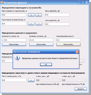
Рис.1.
Расчет произведения высот установки
антенн.

Рис.
2. Протокол решения задачи нахождения
высот установки антенн в канале связи
РС-РВ в программе СРС ЦСС.
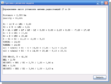
Рис.
3. Протокол решения задачи нахождения
высот установки антенн в канале связи
РС-РН в программе СРС ЦСС.
Соседние файлы в предмете [НЕСОРТИРОВАННОЕ]
- #
- #
- #
- #
- #
- #
- #
- #
- #
- #
- #
The table below shows the functions available by
¥ short press — quickly pressing and releasing
the programmable buttons, or
¥ long press — pressing and holding the
programmable buttons for a period of time
(programmable by your dealer) before
releasing, or
Button
Monitor
Volume Set
Scan
Starts or stops the Scan operation.
Nuisance Channel
Deletes a nuisance channel while scanning.
Delete
Toggles your radioÕs transmit power level between High
Power Level
and Low settings.
Repeater/
Toggles between using a repeater and transmitting
Talkaround
directly to another radio.
Toggles your radioÕs squelch level between tight and
Squelch
normal settings.
Keypad Lock*
Locks or unlocks your radioÕs keypad.
Phone
Makes a Phone Call.
Speed Dial
Accesses the phone numbers in your phone list.
Light
Turns on your radioÕs backlight.
* Activated by long press only.
Depending on how your radio has been
programmed by your dealer, these functions are
activated EITHER through short press OR long
press, but NOT both.
Short Press/Long Press
Ñ
Ñ
¥ hold down- pressing and holding down the
programmable buttons while checking status
or making adjustments.
Hold Down
Monitors the selected channel for
any activity.
Sounds a tone for adjusting the
radioÕs volume level.
Ñ
Ñ
Ñ
Ñ
Ñ
Ñ
Ñ
Ñ
Ñ
English
5
Professional Radio
P080
User Guide
68P64110B68
Issue: September 1999
Radio Communications Supply &
Installation Specialist
Website www.radiotronics.co.uk
Email [email protected]
Telephone Numbers
0345 0 955 955
02087 190 180
Motorola P080 User Guide
CONTENTS
Radio Overview . . . . . . . . . . . . . . . . . . . . 3
Parts of the Radio . . . . . . . . . . . . . . . . . . . 3
On-Off/Volume Knob. . . . . . . . . . . . . . . 4
Channel Selector Knob . . . . . . . . . . . . . 4
Push-to-Talk (PTT) Button . . . . . . . . . . 4
Microphone . . . . . . . . . . . . . . . . . . . . . . 4
LED Indicator . . . . . . . . . . . . . . . . . . . . 4
Programmable Buttons . . . . . . . . . . . . . 4
Menu Keys . . . . . . . . . . . . . . . . . . . . . . 6
Keypad Keys . . . . . . . . . . . . . . . . . . . . . 6
LCD Screen . . . . . . . . . . . . . . . . . . . . . 6
Indicator Tones . . . . . . . . . . . . . . . . . . . . . 8
Programmable ButtonsÕ Audio Indicators. . 8
Improved Audio Features. . . . . . . . . . . . . . 8
Low Level Expansion (LLE) . . . . . . . . . 8
Companding . . . . . . . . . . . . . . . . . . . . . 8
Getting Started . . . . . . . . . . . . . . . . . . . . . 9
Battery Information. . . . . . . . . . . . . . . . . . . 9
Battery Care and Tips . . . . . . . . . . . . . . 9
Recycling or Disposal of Batteries . . . 10
Charging your Battery . . . . . . . . . . . . . 10
Accessory Information . . . . . . . . . . . . . . . 11
Attaching the Battery . . . . . . . . . . . . . .11
Removing the Battery . . . . . . . . . . . . . .11
Attaching the Antenna . . . . . . . . . . . . .12
Removing the Antenna . . . . . . . . . . . . .12
Attaching the Belt Clip . . . . . . . . . . . . .13
Removing the Belt Clip . . . . . . . . . . . . .13
Turning the Radio On or Off . . . . . . . . . . .14
Adjusting the RadioÕs Volume . . . . . . . . . .14
Selecting a Radio Channel . . . . . . . . . . . .14
Sending a Call . . . . . . . . . . . . . . . . . . . . . .15
Receiving a Call. . . . . . . . . . . . . . . . . . . . .15
Radio Call Information . . . . . . . . . . . . . .16
Repeater or Talkaround Mode. . . . . . . . . .16
Setting Tight or Normal Squelch . . . . . . . .16
Setting the Power Level. . . . . . . . . . . . . . .17
Scan . . . . . . . . . . . . . . . . . . . . . . . . . . . . .18
Starting or Stopping a Scan Operation . . .18
Talkback . . . . . . . . . . . . . . . . . . . . . . . . . .19
Deleting a Nuisance Channel . . . . . . . . . .19
Adding a Deleted Nuisance Channel back to the Scan List . . . . . . . . . . . . . . . . .19
Prioritization of a Scan List member . . . . .19
1
English
Phone . . . . . . . . . . . . . . . . . . . . . . . . . . . 20
Making a Phone Call . . . . . . . . . . . . . . . . 20
Entering the Phone Mode . . . . . . . . . . 20
Sending the Access Code. . . . . . . . . . 20
Sending the Phone Number . . . . . . . . 21
The Phone Conversation . . . . . . . . . . 22
Ending the Phone Call . . . . . . . . . . . . 22
Phone List . . . . . . . . . . . . . . . . . . . . . . . . 23
Adding an Entry to the Phone List . . . 23
Deleting an Entry . . . . . . . . . . . . . . . . 23
Editing an Entry. . . . . . . . . . . . . . . . . . 24
Audio/Tone Settings . . . . . . . . . . . . . . . 25
General Instructions . . . . . . . . . . . . . . . . . 25
Utilities . . . . . . . . . . . . . . . . . . . . . . . . . . 26
General Instructions . . . . . . . . . . . . . . . . . 26
Safety Information . . . . . . . . . . . . . . . . . 27
Safe and Efficient Operation of Motorola Two-Way Radios. . . . . . . . . . 27
Exposure To Radio Frequency Energy 27
Portable Radio Operation and EME Exposure . . . . . . . . . . . . . . . 28
Electromagnetic
Interference/Compatibility. . . . . . . . . . .28
Operational Warnings. . . . . . . . . . . . . .28
Operational Cautions . . . . . . . . . . . . . .29
General Radio Care . . . . . . . . . . . . . . .29
Computer Software Copyright
The products described in this manual may include copyrighted computer programmes stored in semiconductor memories or other media. Laws in the
United States of America and other countries preserve for Motorola Europe and Motorola Inc. certain exclusive rights for copyrighted computer programmes, including the right to copy or reproduce in any form the copyrighted computer programme. Accordingly, any copyrighted computer programmes contained in the products described in this manual may not be copied or reproduced in any manner without the express written permission of the holders of the rights. Furthermore, the purchase of these products shall not be deemed to grant either directly or by implication, estoppel, or otherwise, any licence under the copyrights, patents, or patent applications of the holders of the rights, except for the normal non-exclusive royalty free licence to use that arises by operation of the law in the sale of the product.
English 2
RADIO OVERVIEW
PARTS OF THE RADIO
Channel Selector
Knob
On-Off/Volume
Knob
Side Button 1
(programmable)
Side Button 2
(programmable)
Push-to-Talk
(PTT) Button
LED Indicator
Microphone
LCD Screen
Menu Keys
Keypad
Dust Cover covering the
Accessories
Port
(Pull down from
top to open)
3
English
On-Off/Volume Knob
Turns the radio on or off, and adjusts the radioÕs volume.
Channel Selector Knob
Switches the radio to different channels.
Push-to-Talk (PTT) Button
Press and hold down to talk; release it to listen.
Microphone
Speak clearly into the microphone when sending a message.
LED Indicator
Provides visual feedback on radio status. The operation of the indicator depends upon how the radio has been programmed by your dealer.
Basic Features
LED State/Colour
Radio Call
Continuous Red
Blinking Red
Scan
Blinking Green
Low Battery
Blinking Red when sending message
Indication
Sending message.
Receiving message.
Scanning for activity.
Low battery level.
Optional Transmit Power Level Indicator
LED State/Colour
Power Level
Continuous Red
Continuous Green
Indication
Sending message in high power.
Sending message in low power.
Optional Transmit Battery Status Indicator
LED State/Colour
Battery Status
(while pressing PTT)
Blinking Green
Continuous Green
Continuous Orange
Continuous Red
Blinking Red
Indication
Battery is fully charged.
Battery is optimally charged.
Battery is half charged.
Low battery level.
Very low battery level.
Programmable Buttons
Your radioÕs two side buttons can be programmed by your dealer as short-cut buttons for many of the radioÕs features.
Check with your dealer for a complete list of the functions your radioÕs programmable buttons support.
English 4
The table below shows the functions available by
¥
short press
— quickly pressing and releasing the programmable buttons, or
¥
long press
— pressing and holding the programmable buttons for a period of time
(programmable by your dealer) before releasing, or
¥
hold down
— pressing and holding down the programmable buttons while checking status or making adjustments.
Depending on how your radio has been programmed by your dealer, these functions are activated
EITHER
through short press
OR
long press, but
NOT
both.
Button
Monitor
Short Press/Long Press
Ñ
Hold Down
Monitors the selected channel for any activity.
Sounds a tone for adjusting the radioÕs volume level.
Ñ
Ñ
Volume Set Ñ
Scan
Nuisance Channel
Delete
Starts or stops the Scan operation.
Deletes a nuisance channel while scanning.
Power Level
Repeater/
Talkaround
Toggles your radioÕs transmit power level between High and Low settings.
Toggles between using a repeater and transmitting directly to another radio.
Squelch
Toggles your radioÕs squelch level between tight and normal settings.
Locks or unlocks your radioÕs keypad.
Keypad Lock*
Phone
Speed Dial
Makes a Phone Call.
Accesses the phone numbers in your phone list.
Light Turns on your radioÕs backlight.
* Activated by long press only.
Ñ
Ñ
Ñ
Ñ
Ñ
Ñ
Ñ
5
English
Menu Keys
Exit
(
Up
<
>
Menu/Select
)
Down
Menu/Select Key
Enters Menu Mode. When already in Menu Mode, makes Menu selections.
Exit Key
Backs up one level in the Menu hierarchy (short press); also exits the Menu Mode (long press).
Up Key
Used for scrolling when in Menu Mode. Used as a backspace key when editing.
Down Key
Used for scrolling when in Menu Mode. Moves the cursor right or inserts a space when editing.
Keypad Keys
1 2 3
4 5 6
7 8 9
* 0 #
Used to dial a phone number or enter programming list entries.
When entering information for the programming lists, each key can generate numeric information.
LCD Screen
Used to display channel, menu as well as other iconic information.
A B C D E F G H J
English 6
Symbol
A
B
D
G
E
C
Name and Description
Companding Indicator
Indicates that companding is active.
Power Level Indicator
ÒLÓ is lit up when your radio is conÞgured to transmit in Low Power, while ÒHÓ is lit up when your radio is conÞgured to transmit in High Power.
Phone Indicator
Indicates that you are performing a
Phone operation.
Scan Indicator
Indicates that you have activated the
Scan feature.
Priority 1 Scan Indicator ( ßashing )
During Scan, indicates that there is some activity on a Priority 1 channel.
Monitor Indicator
Indicates that you are monitoring the selected channel.
Symbol
F
G
H
J
Name and Description
Talkaround Indicator
When lit, indicates that you are not transmitting through the repeater. When not lit, you are transmitting through the repeater.
Programming Mode Indicator
Indicates that you are editing one of the
Program Lists.
Keypad Lock Indicator
Indicates that your keypad is locked.
Option Board Indicator
Indicates that an option board is activated.
7
English
INDICATOR TONES
High pitched tone Low pitched tone
Self Test Pass Tone
Self Test Fail Tone
Positive Indicator Tone
Negative Indicator Tone
PROGRAMMABLE BUTTONSÕ AUDIO
INDICATORS
Some programmable keys function as toggles
(alternating between two different choices). These keys use audio indicators to indicate the change.
Button
Scan
Power
Level
Squelch*
Positive
Indicator Tone
Start
Scan operation
Radio transmits at
high
power
Radio operates in
tight
squelch
Negative
Indicator Tone
Stop
Scan operation
Radio transmits at
low
power
Radio operates in
normal
squelch
English 8
Button
Positive
Indicator Tone
Negative
Indicator Tone
Repeater/
Talkaround
Keypad
Lock
Radio use the repeater
RadioÕs keypad is
locked
DOES NOT
.
Radio uses the repeater
RadioÕs keypad is
unlocked
.
* There is no visual indicator for the Squelch function.
IMPROVED AUDIO FEATURES
Your radio may be programmed by your dealer to utilise ONE of the following audio enhancement features.
Low Level Expansion (LLE)
LLE improves voice quality by reducing unwanted background noise when receiving a message. It is compatible with most major types of audio processing systems available today.
Companding
Companding improves voice quality by compressing your voice at transmission, and expanding it when receiving. Companding also reduces extraneous noise. However, to enjoy this beneÞt,
ALL
transmitting and receiving radios must have this feature activated.
GETTING STARTED
BATTERY INFORMATION
Battery Care and Tips
This product is powered by a nickel-cadmium (NiCd) or a nickel-metal-hydride (NiMH) rechargeable battery.
The following battery tips will help you obtain the highest performance and longest cycle life from your
Motorola rechargeable battery.
¥ Charge your new battery overnight (
14-16 hours
) before using it to obtain maximum battery capacity and performance.
¥ Charging in non-Motorola equipment may lead to battery damage and void the battery warranty.
¥ When charging a battery that is attached to the radio, turn the radio off to ensure a full charge.
¥ The battery should be at about 25¡C (room temperature) whenever possible. Charging a cold battery (below 10¡C) may result in leakage of electrolyte and ultimately, in failure of the battery.
¥ Charging a hot battery (above 35¡C) results in reduced discharge capacity, affecting the performance of the radio. Motorola rapid-rate battery chargers contain a temperature-sensing circuit to ensure that the battery is charged within these temperature limits.
¥ New batteries can be stored up to two years without signiÞcant cycle loss. Store new/unused batteries in a cool dry area.
¥ Batteries which have been in storage should be charged overnight.
¥ Do not return fully charged batteries to the charger for an Òextra boostÓ. This action will
signiÞcantly
reduce cycle life.
¥ Do not leave your radio and battery in the charger when not charging. Continuous charging will shorten battery life. (Do not use your charger as a radio stand.)
¥ For optimum battery life and operation use only
Motorola brand chargers. They were designed to operate as an integrated energy system.
9
English
Recycling or Disposal of
Batteries
NiCd
At the end of its useful life, the NiCd battery can be recycled. However, recycling facilities may not be available in all areas.
Motorola endorses and encourages the recycling of all re-chargeable batteries. Contact your local
Motorola dealer for further information.
Charging your Battery
When the battery level is very low, a blinking red
LED indicator lights up during transmit mode, and an alert tone sounds. You will need to recharge the battery before you can continue to use your radio.
Place the radio with the battery attached or the battery alone in the charger. The chargerÕs LED indicator will indicate the charging progress.
NOTE:
Since new batteries or batteries that have not been used for several months could prematurely indicate full charge (solid green
LED), charge the batteries for 14 to 16 hours prior to initial use to achieve optimal performance.
LED color Status
Single ßash of Green
Flashing Red*
Flashing Yellow
Successful charger power-up.
Battery is unchargeable.
Charger is getting ready to charge.
Red
Flashing Green
Green
Battery is charging.
Battery is 90% charged.
Battery is fully charged.
* Remove the battery from charger and use a pencil eraser to clean the four metal contacts on the bottom of the battery.
Place the battery back into the charger. If the LED indicator continues to ßash red, replace the battery.
A standard battery may require one hour to charge to 90% capacity.
English 10
ACCESSORY INFORMATION
Attaching the Battery
Removing the Battery
battery latches
2
2
3
1
1.
2.
Fit the extensions at the bottom of the battery into the slots at the bottom of the radioÕs body.
Press the top part of the battery toward the radio until you hear a click.
1.
2.
3.
Turn off the radio, if it is turned on.
Slide the battery latches on both sides of the battery downwards.
Pull the top part of the battery away from the radio body.
11
English
Attaching the Antenna Removing the Antenna
Turn the antenna clockwise to attach it.
English 12
Turn the antenna counter-clockwise to remove it.
Attaching the Belt Clip Removing the Belt Clip
belt clip tab
1
2
1.
2.
Align the grooves of the belt clip with those of the battery.
Press the belt clip downward until you hear a click.
1.
2.
Use a key to press the belt clip tab away from the battery.
Slide the belt clip upward to remove it.
13
English
TURNING THE RADIO ON OR OFF
1.
2.
ON OFF
Turn the
On-Off/Volume Control
knob clockwise to turn on the radio. You will hear the
Self Test Pass Tone ( ) and see a green LED if the radio powers up successfully. If the radio fails its self test, you will hear the Self Test Fail Tone ( ). Switch off and on again and if fault persists contact your dealer.
To turn off the radio, turn the
On-Off/Volume
Control
knob counter-clockwise, until you hear a click.
ADJUSTING THE RADIOÕS VOLUME
If one of the radio side buttons has been programmed as a Volume Set button by your dealer, it may be used as follows:
1.
2.
3.
Press and hold the preprogrammed
Volume
Set
button; you will hear a continuous tone.
Turn the
On-Off/Volume Control
knob and adjust the volume level.
Release the preprogrammed
Volume Set
button.
SELECTING A RADIO CHANNEL
Your radio offers 16 channels for easy access to required conventional channels. Some channels on your radio may not be programmed. Check with your dealer for more information.
Turn the
Channel Selector
knob clockwise or counter-clockwise until you reach the desired channel.
English 14
SENDING A CALL
1.
2.
3.
4.
Turn your radio on.
Use the
Channel Selector
knob to select the desired channel.
Hold the radio in a vertical position, press the
PTT
button, and talk at a distance of about
2.5 to 5 cm (one to two inches) from the microphone.
Release the PTT button to listen.
RECEIVING A CALL
1.
Turn your radio on.
2.
Adjust the radioÕs volume.
3.
Switch to the desired channel.
4.
If at any time a call comes through, you will hear the call at the volume level you have set.
15
English
RADIO CALL INFORMATION
REPEATER OR TALKAROUND MODE
Talkaround Mode enables you to communicate with another radio when either:
¥ the repeater is not operating
ÑorÑ
¥ your radio is out of the repeaterÕs range but within communicating distance of another radio.
NOTE: The
F symbol will appear on the LCD screen when Talkaround Mode is selected.
To select either Repeater Mode or Talkaround
Mode:
Press the Repeater/Talkaround button (only available if programmed by your dealer) to toggle between the two modes. A positive indicator tone indicates that the radio is in talkaround mode, while a negative indicator tone indicates that the radio is in repeater mode.
ÑorÑ
1.
) to enter Menu Mode.
2.
<
or
> until
TLK ARD
3.
4.
5.
) to select
<
or
> until
(talk through repeater),
TLK ARD
OFF
or
until
(talk directly without going through repeater).
)
to select the desired option.
ON
SETTING TIGHT OR NORMAL SQUELCH
Use this feature to Þlter out nuisance (unwanted) calls and/or background noise. However, tightening squelch could cause calls from remote locations to be Þltered out as well. In this case, normal squelch may be more desirable.To select tight or normal squelch:
Press the Squelch button (only available if programmed by your dealer) to toggle between tight and normal squelch. A positive indicator tone indicates that the radio is operating in tight squelch, while a negative indicator tone indicates that the radio is operating in normal squelch.
English 16
1.
2.
ÑorÑ
) to enter Menu Mode.
<
or
> until
3.
) to select
4.
<
or
> until
UTILITY
UTILITY
SQUELCH
5.
6.
7.
) to select
< or > until
(tighten channelÕs squelch),
SQUELCH
TIGHT
or
until
(channel operates under normal squelch).
NORMAL
)
to select the squelch setting.
SETTING THE POWER LEVEL
Your radio has a predeÞned transmit power level that can be changed.
¥ High power (H icon) allows the radio to transmit over greater distances.
¥ Low power (L icon) conserves the batteryÕs charge.
To set the power level:
Press the Power Level button (only available if programmed by your dealer) to toggle between low and high transmit power level. A positive indicator tone indicates that the radio is in high power mode, while a negative indicator tone indicates that the radio is in low power mode.
ÑorÑ
1.
) to enter Menu Mode.
2.
<
or
> until
UTILITY
3.
) to select
4.
<
or
> until
UTILITY
TX PWR
5.
6.
7.
) to select
<
or
> until
(to transmit at high power),
or
until
(to transmit at low power).
)
to select the power level.
TX PWR
HIGH
LOW
17
English
SCAN
You can monitor several channels in order to receive any call that is transmitted on any of these channels.
Sixteen different channels can be programmed into each scan list by the dealer.
Once the radioÕs scan operation is activated and the radio detects a call coming through a channel in its scan list, it switches to that channel for you to receive the call.
STARTING OR STOPPING A SCAN
OPERATION
The
E symbol, and the channel you are transmitting on, will appear on the LCD screen when you start a scan operation.
The LED indicator blinks green during a scan operation.
NOTE: If you enter Menu Mode while the radio is scanning, scanning will stop. It will resume when you exit Menu Mode.
To start or stop a scan operation:
1.
Press the Scan button (only available if programmed by your dealer) to start a scan operation. You will hear a positive indicator tone.
2.
Press the preprogrammed Scan button again to stop the scan operation. You will hear a negative indicator tone.
1.
2.
ÑorÑ
) to enter Menu Mode.
<
or
> until
SCAN
3.
4.
5.
) to select
<
or
> until
(to start a scan operation),
SCAN
ON
or
until
(to stop a scan operation).
) to select the desired option.
OFF
NOTE: The LED indicator will blink (green) during a scan operation.
English 18
TALKBACK
If the programmable Talkback option is set, you can respond to any calls received during the scan operation by pressing the PTT before the programmed hang-time ends. Check with your dealer for details.
ADDING A DELETED NUISANCE CHANNEL
BACK TO THE SCAN LIST
1.
Press the Scan button to stop the scan operation.
2.
Press the Scan button again to re-start the scan operation. The Deleted Nuisance
Channel is reinstated to the scan list.
DELETING A NUISANCE CHANNEL
If a channel continually generates unwanted calls or noise (a ÒnuisanceÓ Channel), you can temporarily remove it from the scan list by performing a
Nuisance Channel Delete operation.
1.
While the radio is on the Nuisance Channel, press the Nuisance Channel Delete button
(only available if programmed by your dealer) until you hear a tone.
2.
Release the Nuisance Channel Delete button. The nuisance channel is deleted.
NOTE: You cannot perform a Nuisance Channel
Delete on a priority channel or if there is only one remaining channel in the scan list.
PRIORITIZATION OF A SCAN LIST
MEMBER
You may want your radio to check a particular channel more frequently for calls. Prioritization of scan list members is done by your dealer using the
Customer Programming Software. Check with your dealer for details.
Priority Channel
None speciÞed
Channel 2
Scanning Sequence
Ch1
➠
Ch2
➠
Ch3
➠
Ch4
➠…
Ch1
Ch2
➠
Ch1
➠
Ch2
➠
Ch3
➠
Ch2
➠
Ch4
➠
Ch2
➠
…Ch1
Even though your radio has switched to a nonpriority channel, your radio will still check for activity on the priority channel. If activity is detected the radio will switch to the priority channel.
19
English
PHONE
You can use your radio to connect to a phone line to make a phone call.
To do this, your radio must send an access code to a station that connects it to a phone line. After you have Þnished your call, the radio has to send a deaccess code to shutdown the connection to the phone line.
1. Press the Phone button.
To enter the Phone mode via the menu:
1.
) to enter Menu Mode.
2.
<
or
> until
PHONE
Entering the Phone Mode
Before you can make a phone call, you must enter the radioÕs Phone mode.
3.
) to select
You will see the last phone number dialled; for example
Method
Manual
Automatic
Delayed
Automatic
Immediate
PHONE
5554567
MAKING A PHONE CALL
You can make a phone call by using the menu or by using the programmed Phone button (if Phone operation is permitted on the current channel). The
D
icon will light up on the LCD screen when you are in Phone mode.
A complete phone session consists of
¥ entering the Phone mode
¥ sending the access code
¥ sending the phone number
¥ having the phone conversation
¥ ending the phone call.
Sending the Access Code
Your radio can be programmed to send the access code in any of the following ways:
¥ manual
¥ automatic delayed
¥ automatic immediate.
Check with your dealer for more details.
Steps to Take
Dial the access code from the keypad.
Press and release the PTT; the radio automatically sends the preprogrammed access code.
You do not have to do anything; the radio immediately sends the access code when it enters phone mode.
English 20
Sending the Phone Number
After the access code is sent, you should wait for a dialling tone before sending your phone number.
You can send
¥ a phone number that is stored in the radio, or
¥ a new number.
Additionally, depending on how your radio is programmed, if you use the keypad to send a number, the radio can send the numbers in one of the following ways:
¥ live dial
¥ buffered dial.
Check with your dealer for details.
Sending a Stored Phone Number
You can access the stored phone numbers by
¥ recalling the last number dialled,
¥ using the phone list, or
¥ using the speed dial feature.
Method
Last
Number
Redial
*
Steps to Take
Press and release the PTT; the radio sends the last number dialled.
Method Steps to Take
Phone
List
1. Press
< or > to scroll the phone list until you reach the desired phone number.
2. Press and release the PTT to send the number.
Speed
Dial
1. Press and release the programmed Speed
Dial button.
2. Press the numbered keys (1-9) corresponding to the Þrst nine phone numbers in the phone list. Press Ò0Ó if you want the last number dialled.
3. If your radio uses buffered dial, press and release the PTT.
4. The radio sends out the phone number.
*
The method described is not applicable for radios which manually send the access code; these radios can access this number from the phone list or the speed dial.
For radios that manually send the access code, press the
Down Key once to access the last number dialled.
21
English
Sending a New Number
You enter the phone number by pressing the relevant keys on the keypad.
Method
Live Dial
Buffered
Dial
Steps to Take
Enter the phone number by using the keypad; the radio sends out the numbers as the keys are pressed.
1. Enter the phone number by using the keypad; the radio saves the selected numbers in a buffer.
2. Press and release the PTT; the radio sends out the numbers in its buffer.
The Phone Conversation
Once the radio has connected to the intended party, you can begin the conversation. Even though this is a phone call, your conversation mimics a radio call
(that is, both parties speak in turn).
1.
Press and hold the PTT, while talking into the microphone.
2.
Release the PTT when you Þnish what you want to say, and wait for the response.
3.
Repeat steps 1 and 2 until the conversation ends.
Ending the Phone Call
Just as the radio needs to send the access code when starting a phone call, the radio needs to send the deaccess code to end the phone call.
The radio can send the deaccess code in any of the following ways:
¥ manual, and
¥ automatic.
Check with your dealer for details.
1.
If your radio sends the deaccess code manually, dial the deaccess code from the keypad.
2.
Press the Phone button to exit phone mode.
NOTE: Radios using the automatic method will send the deaccess code automatically.
or
Exit the phone mode using the menu:
( to exit phone mode and return to
PHONE
or
Hold
( to exit the Menu Mode.
NOTE: Radios using the automatic method will send the deaccess code automatically.
English 22
PHONE LIST
Your radio can store a list of frequently accessed phone numbers. The
G icon will light up on the
LCD screen when you edit the phone list.
NOTE: The radio will not receive any calls when you are editing the phone list.
Adding an Entry to the Phone List
1.
2.
) to enter Menu Mode.
<
or
> until
3.
) to select
4.
<
or
> until
5.
) to select
6.
<
or
> until
7.
) to select
You will see
PROGRAM
PROGRAM
PHONE
PHONE
ADD
ADD
NUMBER
8.
Use the keypad to enter the phone number.
9.
Press the numeric keys to enter the numbers.
You can also add a dash (press
>
) and a
Pause Indicator (press and hold
#
the key until the
#
character on the LCD screen changes to a Ò
P
Ó).
)
to store the phone number.
)
again to conÞrm its storage.
10.
( to return to
ADD
or
Hold
( to exit Menu Mode.
1.
2.
Deleting an Entry
) to enter Menu Mode.
<
or
> until
PROGRAM
3.
) to select
4.
<
or
> until
5.
) to select
PROGRAM
PHONE
PHONE
23
English
6.
<
or
> until
DELETE
7.
8.
9.
10.
) to select
DELETE
<
or
> until you see the entry you wish to delete.
)
to select the entry.
)
again to conÞrm the deletion.
( to return to
DELETE
or
Hold
( to exit Menu Mode.
Editing an Entry
1.
2.
) to enter Menu Mode.
<
or
> until
3.
) to select
4.
<
or
> until
5.
) to select
PROGRAM
PROGRAM
PHONE
PHONE
6.
<
or
> until
EDIT
7.
8.
9.
) to select
EDIT
<
or
> until you see the entry you wish to edit.
)
to select the entry.
or until
(to edit the entryÕs phone number),
NUMBER
11.
or until
(to edit the entryÕs location in the phone list).
)
to select the edit type.
LOCATN
12. Use the keypad to edit the entry. See Key-
pad Keys on page 6.
13.
)
to store the information.
14.
( to return to
EDIT
or
Hold
( to exit Menu Mode.
English 24
AUDIO/TONES SETTINGS
The Audio/Tones menu allows you to customize the audio and tone settings on your radio.
GENERAL INSTRUCTIONS
1.
) to enter Menu Mode.
2.
<
or
> until
3.
) to select
TONES
TONES
4.
5.
6.
7.
<
or
> until you see the audio/tone setting you wish to change.
) to select the tones setting. You will see the current status of the setting.
<
or
> to see the available optional settings.
)
to select the desired setting.
Use instructions above to change your radioÕs audio and tones settings shown in the table below.
Menu Items
ALERT
KEYPAD
Optional Settings
ON
OFF
ON
OFF
Function
Allows you to turn all tones on or off.
Allows you to turn the tones associated with the radio keys on or off.
25
English
UTILITIES
The Utilities menu allows you to customize some general settings on your radio.
GENERAL INSTRUCTIONS
1.
) to enter Menu Mode.
2.
<
or
> until
3.
) to select
UTILITY
UTILITY
4.
5.
6.
7.
<
or
> until you see the setting that you wish to change.
) to select the setting to change. You will see the current status of the setting.
<
or
> to see the available optional settings.
)
to select the desired setting.
Use the instructions above to change your radio settings shown in the table below.
Menu Items
SQUELCH
TX PWR
LIGHT
SOFTWAR
Optional Settings
NORMAL
TIGHT
HIGH
LOW
ON
OFF
Function
Allows you to change the squelch setting of the radio between normal and tight.
Allows you to change the power level of the radio between high or low.
Allows you to turn the back-light feature of the radio on or off.
Allows you to identify the version number of the software within the radio.
English 26
SAFETY INFORMATION
Safe and EfÞcient Operation of Motorola
Two-Way Radios
This section provides information and instructions for the safe and efÞcient operation of Motorola Portable and Mobile Two-Way Radios.
For information regarding radio use in hazardous areas, please refer to the Factory Mutual (FM) approval manual supplement or Instruction Card which is included with radio models that offer this capability.
Exposure To Radio Frequency Energy
National and International Standards and
Guidelines
Your Motorola Two-Way Radio, which generates and radiates radio frequency (RF) electromagnetic energy
(EME) is designed to comply with the following National and International Standards and Guidelines regarding exposure of human beings to radio frequency electromagnetic energy:
¥ Federal Communications Commission Report and
Order No. FCC 96-326 (August 1996)
¥ American National Standards Institute
(C95.1 — 1992)
¥ National Council on Radiation Protection and
Measurements (NCRP — 1986)
¥ International Commission on Non-Ionizing Radiation Protection (ICNRP — 1986)
¥ European Committee for Electrotechnical
Standardisation (CENELEC):
¥ ENV. 50166-1
1995 E
¥ ENV. 50166-2
1995 E
¥ Proceedings of
SC211/8 1996
Human Exposure to Electromagnetic Fields Low Frequency (0Hz to 10kHz)
Human Exposure to Electromagnetic Fields High Frequency (10kHz to 300GHz)
Safety Considerations for
Human Exposure to E.M.F.s from Mobile Telecommunications Equipment (M.T.E.) in the Frequency Range
30MHz — 6 GHz (E.M.F. —
Electromagnetic Fields)
To assure optimal radio performance and that human exposure to radio frequency electromagnetic energy is within the guidelines set forth in the above standards, always adhere to the following procedures:
27
English
Portable Radio Operation and
EME Exposure
When transmitting with a portable radio, hold the radio in a vertical
MAN WITH RA position with its microphone 2.5 to 5 centimeters (1 to 2 inches) away from your mouth.
Keep antenna at least 2.5 centimeters (1 inch) from your head and body.
If you wear a portable two-way radio on your body, ensure that the antenna is at least 2.5 centimeters
(1 inch) from your body when transmitting.
Electromagnetic Interference/Compatibility
Note: Nearly every electronic device is susceptible to electromagnetic interference (EMI) if inadequately shielded, designed or otherwise conÞgured for electromagnetic compatibility.
To avoid electromagnetic interference and/or compatibility conßicts, turn off your radio in any facility where posted notices instruct you to do so.
Hospitals or health care facilities may be using equipment that is sensitive to external RF energy.
When instructed to do so, turn off your radio when on board an aircraft. Any use of a radio must be in accordance with airline regulations or crew instructions.
Operational Warnings
!
!
W A R N I N G
Vehicles With an Air Bag
Do not place a portable radio in the area over an air bag or in the air bag deployment area. Air bags inßate with great force. If a portable radio is placed in the air bag deployment area and the air bag inßates, the radio may be propelled with great force and cause serious injury to occupants of the vehicle.
Potentially Explosive Atmospheres
Turn off your two-way radio when you are in any area with a potentially explosive atmosphere, unless it is a radio type especially qualiÞed for use in such areas (for example, Factory
Mutual). Sparks in a potentially explosive atmosphere can cause an explosion or Þre resulting in bodily injury or even death.
Batteries
Do not replace or recharge batteries in a potentially explosive atmosphere. Contact sparking may occur while installing or removing batteries and cause an explosion.
English 28
Blasting Caps and Areas
To avoid possible interference with blasting operations, turn off your radio when you are near electrical blasting caps, in a blasting area, or in areas posted: ÒTurn off two-way radio.Ó Obey all signs and instructions.
Note:
The areas with potentially explosive atmospheres referred to above include fueling areas such as: below decks on boats; fuel or chemical transfer or storage facilities; areas where the air contains chemicals or particles, such as grain, dust or metal powders; and any other area where you would normally be advised to turn off your vehicle engine.
Areas with potentially explosive atmospheres are often but not always posted.
Operational Cautions
!
C a u t i o n
Damaged Antennas
Do not use any portable two-way radio that has a damaged antenna. If a damaged antenna comes into contact with your skin, a minor burn can result.
Batteries
All batteries can cause property damage and/or bodily injury such as burns if a conductive material such as jewellery, keys, or beaded chains touch exposed terminals. The conductive material may complete an electrical circuit (short circuit) and become quite hot. Exercise care in handling any charged battery, particularly when placing it inside a pocket, purse, or other container with metal objects.
General Radio Care
¥ The use of chemicals such as detergents, alcohol, aerosol
!
sprays, and/or petroleum
C a u t i o n
products may be harmful to and damage the radio housing.
¥ Avoid physical abuse of the radio such as carrying it by the antenna.
¥ The accessory connector (if Þtted) has a protective cap which should be left in place when the connector is not in use.
¥ Clean the radio exterior using a cloth moistened with clean water and a mild dishwashing liquid.
¥ The use of non-approved radio accessories may damage the radio and invalidate warranty.
29
English
NOTES
English 30