MOXA NPort 5150, 5130, 5110 преобразователи интерфейсов RS-232/422/485 в Ethernet отличаются интерфейсами как изображено на рисунке ниже:

Сброс настроек
Для сброса настроек преобразователя интерфейсов серии 5100 воспользуйтесь кнопкой перезагрузки reset расположенной на корпусе. Для установки настроек по умолчанию необходимо нажать и удерживать кнопку reset в течении пяти секунд, до тех пор, пока не перестанет мигать светодиодный индикатор ready.
- Купить преобразователь Nport 5150 по дилерским ценам со склада можно отправив запрос в свободном формате на почту или через карточку товара
Светодиодные индикаторы
На верхней̆ панели сервера NPort 5100 расположены три светодиодных индикатора.

Построечные резисторы Pull High/Pull Low сигналов RS-422/485 (150 КОм или 1 КОм)
Для установки значений pull high/low используйте построечные резисторы, расположенные с обратной стороны на корпусе. Значение по умолчанию – 150 КОм. Замкните джемперы для установки значения 1 КОм. Не рекомендуется использовать значение 1 кОм для режима передачи данных RS-232, Поскольку это приводит к ухудшению сигнала RS-232 и уменьшению дальности связи.

Распиновка
Выводы ethernet порта расположены как указано на рисунках ниже:
NPort 5110 – Расположение выводов разъема DB9 «папа» (RS-232)

NPort 5130 – Расположение выводов разъема DB9 «папа» (RS-422/485)

NPort 5150 – Расположение выводов разъема DB9 «папа» (RS-232/422/485)

Технические спецификации
В комплект поставки преобразователей интерфейсов 5150, 5130 и 5110 входят:
- — Сервер серии NPort 5100
- — Адаптер питания 100-240 В переменного тока, кроме моделей̆ работающих в расширенном диапазоне температур
- — 4 противоскользящие подушки
- — CD с документацией̆ и ПО
- — Руководство по аппаратной̆ установке
- — Гарантийный̆ талон
Крепеж для din-рейки 35мм DK-35A включается опционально.
Модели с литером —Т обозначают устройства, работающие в расширенном температурном диапазоне.


11.07.2019 г.
В статье рассматриваем настройку самых востребованных режимов работы: RealCOM — виртуальный СОМ порт на ПК, TCP Client, TCP Server.
Не путайте NPort со шлюзами MGate. NPort преобразует только интерфейсы СОМ в Ethernet и не изменяет данные, а MGate преобразует интерфейсы и протоколы, подробнее в статье об отличиях NPort и MGate.

Содержание:
- Видеообзор возможностей NPort
-
Настройка NPort
- Режим RealCOM или Виртуальный COM-порт
- Режим TCP Client
- Режим TCP Server
- Как проверить работает ли NPort?
- Подтягивающие и согласующие резисторы
Специалисты IPC2U сделали настолько подробный обзор конфигурации NPort, насколько это возможно. В видео показаны пошаговые действия по настройке NPort с помощью бесплатной утилиты и рассмотрены режимы работы (с подробным описанием и анимированным иллюстрациями). В ходе ролика мы подключим модуль M-7055D, который работает по протоколу Modbus RTU, и отправим на него команду для включения дискретных выходов. Также рассмотрим, как проверить правильность работы NPort без необходимости подключать дополнительные модули.
Дополнительно в третьей части видео показаны «секреты» NPort: расширенные функции, о которых мало кто знает, но именно они способны избавить вас от многих причин головной боли инженеров и проектировщиков.
Настройка NPort
Режим RealCOM
Для работы с NPort IA5150 в режиме RealCOM установите драйвер или NPort Administration Suite.
Сначала нужно настроить NPort, а затем добавить СОМ порт либо через драйвер, либо через NPort Administration Suite.
Если вы используете драйвер, то после настройки NPort вы увидите СОМ порт в диспетчере устройств. Если вы используете NPort Administration Suite для добавления СОМ порта, то СОМ порт в диспетчере устройств не отображается.

Настроим NPort в режим RealCOM и добавим виртуальный СОМ порт через NPort Administration Suite. Также можно использовать WEB-интерфейс для настройки.

Найдем NPort выделив поле Configuration и нажав кнопку Search.
После этого нужно разблокировать NPort: нажать правой кнопкой на нем, выбрать Unlock и ввести пароль из документации.

Далее выделяем наш NPort и нажимаем кнопку Configure.
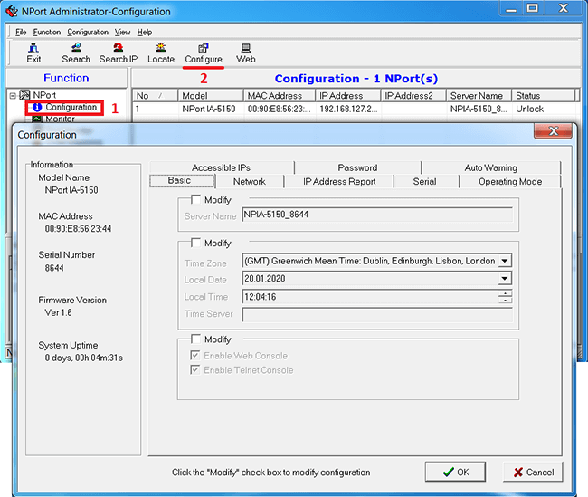
В этом окне можно изменить настройки NPort, достаточно поставить галочку возле поля Modify.
Во вкладке Network можно изменить IP адрес NPort.
Во вкладке Serial настраиваются параметры COM порта: его скорость, тип интерфейса и др.
Для режима RealCOM скорость COM порта будет автоматически изменяться при открытии СОМ порта, а в других режимах здесь нужно указать правильную скорость.

Перейдем во вкладку Operation Mode для настройки режима работы конкретного COM порта.

Выберем режим работы RealCOM, а другие параметры оставим по умолчанию.
После сохранения настроек, NPort перезагрузиться и издаст характерный звук.
Далее добавим виртуальный СОМ порт на ПК (также для этого можно использовать драйвер NPort).
Выделим поле COM Mapping и нажмем кнопку Add.

В программе появится NPort и он будет иметь синий цвет, что значит эта настройка еще не сохранена.

Вы можете изменить номер СОМ порта через кнопку Configure.

После установки всех настроек сохраним их, нажав на кнопку Apply.

Надпись стала черного цвета, что означает все изменения были сохранены.
Для работы с СОМ портом нужна программа, которая позволит открыть СОМ порт и отправить в него данные. MOXA предлагает воспользоваться бесплатной утилитой PComm Lite.
Для проверки работы NPort можно воспользоваться рекомендациями ниже.
Режим TCP Client
Для режима TCP Client во вкладке Serial нужно указать правильную скорость, т.к. она сама не перестраивается.
Во вкладке Operation Mode нужно выбрать режим TCP Client.
Для правильной работы нужно указать IP адрес TCP Server с которым будет установлено соединение и TCP порт. Остальные параметры можно оставить по умолчанию.

Режим TCP Server
Для режима TCP Server во вкладке Serial нужно указать правильную скорость, т.к. она сама не перестраивается.
Во вкладке Operation Mode нужно выбрать режим TCP Server.
Для правильной работы нужно указать TCP порт по которому будет подключаться TCP Client.
Остальные параметры можно оставить по умолчанию.

Как проверить работает ли NPort?
Для проверки RS-232 можно воспользоваться простым способом, достаточно замкнуть контакты RX и TX между собой, что позволяет сделать петлю. Тогда все переданные данные в NPort будут возвращены обратно.

Откройте программу PComm Terminal Emulator, во вкладке Port Manager откройте СОМ порт, соответствующий NPort(в режиме RealCOM). Скорость и другие параметры можно оставить по умолчанию, т.к. драйвер автоматически применяет такие же параметры на NPort.

Мы отправили несколько единиц в СОМ порт и получили их обратно, также видим одинаковые значения счетчиков TX и RX, что подтверждает получение всех отправленных данных.

Подтягивающие и согласующие резисторы
В некоторых моделях NPort есть встроенные резисторы, которые обеспечивают правильную работу линий RS-422/485.
Согласующий резистор или терминатор 120 Ом – ставится в начале и конце линии для предотвращения отражения сигнала от конца линии и искажении полезного сигнала в RS-422/485.
Подтягивающие резисторы (pull high/low resistors) – предназначены для ограничения тока, протекающего по сигнальным цепям, и чтобы сделать состояние цифрового входа по умолчанию высоким или низким.
NPort IA5150 не имеет встроенных резисторов, но у некоторых моделей они есть, пример для других моделей:

Распиновка разъема NPort IA5150


Если у Вас есть вопросы по продукции МОХА, обращайтесь по телефону: +7 (495) 419-1201 или по e-mail: russia@moxa.pro

Серия NPort IA5150
Серия NPort IA5150/5250
Краткое руководство по установке
Третье издание, январь 2006
1. Обзор
Сервер NPort IA – простое и надежное устройство, обеспечивающее
подключение промышленного оборудования с последовательным
интерфейсом к сетям Ethernet. Сервер поддерживает несколько режимов
работы: TCP Server, TCP Client, UDP, Real COM, Pair Connection и
Ethernet Modem. Во всех режимах осуществляется прозрачная передача
данных с интерфейсов RS-232/422/485, гарантируя полную
совместимость с существующим ПО и обеспечивая простое
подключение таких устройств как контроллеры, датчики, измерительные
приборы, двигатели, электроприводы, сканнеры штрих-кода и дисплеи
операторов. NPort IA поставляется в компактном корпусе со встроенным
крепежом на DIN-рейку.
2. Комплект поставки
Перед началом работы с NPort IA убедитесь, что комплект поставки
включает следующие компоненты:
• 1 сервер NPort IA,
• Компакт диск с документацией и ПО,
• Краткое руководство по установке NPort IA.
Опционально:
• DR-4524 источник питания 24 В (пост.), 45Вт/2А; входное
напряжение 85 ~ 264 В (перем.), монтаж на DIN-рейку
• DR-75-24 источник питания 24 В (пост.), 75Вт/3.2А; входное
напряжение 85 ~ 264 В (перем.), монтаж на DIN-рейку
• DR-4524 источник питания 24 В (пост.), 120Вт/5А; входное
напряжение 88 ~ 132 В (перем.) или 176 ~ 264 В (перем.), монтаж на
DIN-рейку.
Сообщите своему торговому представителю, если какой-либо
элемент отсутствует или поврежден.
NPort IA5250
3. Описание аппаратной части
Серверы NPort IA используются для управления устройствами
промышленной автоматизации с интерфейсом RS-232/422/485. Шесть
моделей этой серии имеют 1 последовательный порт RS-232/422/485.
NPort IA5150, NPort IA5150I, NPort IA5150-M-SC, NPort IA5150I-M-SC,
NPort IA5150-S-SC и NPort IA5150I-S-SC оснащены одним портом с
разъемом DB9 «папа» для интерфейса RS-232 и 5-контактным
терминальным блоком для интерфейса RS-422/485 (одновременно
может использоваться только один порт). Одна модель имеет два
последовательных порта с интерфейсом RS-232/422/485. NPort IA5250
имеет два порта DB9 «папа» для всех интерфейсов.
Кнопка перезагрузки (Reset) – нажмите и удерживайте кнопку 5 сек.
для загрузки настроек по умолчанию:
Чтобы нажать на кнопку перезагрузки, используйте тонкий предмет.
После нажатия светодиодный индикатор Ready будет мигать. Как только
индикатор перестанет мигать (примерно через 5 сек.), настройки по
умолчанию будут загружены. После этого отпустите кнопку перезагрузки.
Светодиодные индикаторы (расположены на передней панели
NPort IA)
Название
Цвет
PWR1,
PWR2
красный
красный
RDY
зеленый
Ethernet
P1, P2
выключен
оранжевый
зеленый
выключен
оранжевый
зеленый
выключен
FX
оранжевый
Функция
Питание подается на вход PWR1, PWR2.
Горит: Питание включено и NPort IA
загружается.
Мигает: конфликт IP-адреса, некорректный
ответ сервера DHCP или BOOTP или
срабатывание выхода реле.
Горит: Питание включено и NPort IA работает
нормально.
Мигает: Функция Location утилиты NPort
Administrator указывает на расположение
сервера.
Питание отключено или сбой в питании.
Соединение Ethernet 10 Мбит/сек.
Соединение Ethernet 100 Мбит/сек.
Ethernet-кабель отключен или неисправен.
Последовательный порт принимает данные.
Последовательный порт передает данные.
Последовательный порт не передает и не
принимает данные.
Горит: Ethernet-соединение исправно, порт в
режиме ожидания.
Мигает: Порт передает или принимает данные.
4. Установка устройства.
ШАГ 1: Подключите NPort IA к источнику электропитания. Клеммы
терминального блока NPort IA подключите к линии питания постоянного
тока 12-48 В или к соответствующему адаптеру питания.
ШАГ 2: Подключите NPort IA в сеть. Для подключения к сетевому
концентратору или коммутатору используйте стандартный «прямой»
Ethernet-кабель. Если NPort IA может быть подключен напрямую к
вашему компьютеру через Ethernet-порт, то используйте для соединения
«перекрёстный» Ethernet-кабель.
ШАГ 3: Соедините последовательный порт NPort IA с устройством,
имеющим последовательный интерфейс.
ШАГ 4: NPort IA может быть установлен на DIN-рейку или на стену. Для
обоих способов крепления служат два ползунка на задней панели. Для
монтажа на стену оба ползунка должны быть вытянуты. Для монтажа на
DIN-рейку один ползунок вдавите внутрь, а другой вытяните. После того,
как вы поместите NPort IA на DIN-рейку, нажмите на второй ползунок для
того, чтобы зафиксировать устройство на DIN-рейке. Оба варианта
монтажа показаны на рисунках.
5. Установка ПО
Для установки пакета ПО администратора вставьте диск с
документацией и ПО (Document & Software CD) в дисковод CD-ROM. В
открывшемся окне установки нажмите кнопку Installation Administration
Suite и следуйте инструкциям на экране. Для дополнительной
информации о ПО NPort Administration Suite нажмите кнопку
Documents и выберите NPort IA5150/5250 Series User’s Manual, чтобы
открыть pdf-версию руководства пользователя.
6. Схемы расположения выводов и подключения
кабелей
Расположение выводов разъема RS-232/422/485 (DB9 «папа»):
Вывод
RS-232
1
2
3
4
5
6
7
8
9
DCD
RXD
TXD
DTR
GND
DSR
RTS
CTS
-
RS-422/
RS-485 (4проводный)
TxD-(A)
TxD+(B)
RxD+(B)
RxD-(A)
GND
-
RS-485 (2проводный)
Data+(B)
Data-(A)
GND
7. Технические спецификации
Расположение выводов терминального блока
RS-485/RS-422
Вывод
1
2
3
4
5
2-проводный
Data+(B)
Data-(A)
-
4-проводный
TxD+(B)
TxD-(A)
RxD+(B)
RxD-(A)
GND
Дополнительно доступны два кабеля для подключения NPort IA к
устройствам с последовательным интерфейсом RS-232. Ниже
приведены схемы подключения каждого из двух кабелей.
Кабель DB9 «мама» к DB9 «папа»
Питание:
NPort IA5150:
12 ~ 48 В (пост.), 360 мА (при 12 В)
NPort IA5150I:
12 ~ 48 В (пост.), 420 мА (при 12 В)
NPort IA5150-S-SC:
12 ~ 48 В (пост.), 470 мА (при 12 В)
NPort IA5150I-S-SC: 12 ~ 48 В (пост.), 490 мА (при 12 В)
NPort IA5150- M-SC: 12 ~ 48 В (пост.), 500 мА (при 12 В)
NPort IA5150I- M-SC: 12 ~ 48 В (пост.), 510 мА (при 12 В)
NPort IA5250:
12 ~ 48 В (пост.), 440 мА (при 12 В)
Рабочая температура:
0 ~ 55°С
Относительная влажность:
5 ~ 95%
Габаритные размеры (ШхДхВ):
29 х 89,2 х 118,5 мм
1,14 х 3,51 х 4,67 дюйм
Защита от импульсных помех:
15 КВ для всех сигналов
Электромагнитная изоляция: 1,5 КВ для Ethernet
Защита линий питания:
4 КВ пробой (EFT), EN-61000-4-4
2 КВ перенапряжение, EN61000-4-5
Сертификаты:
FCC Class A, CE Class A, UL, CUL, TÜV
Кабель DB9 «мама» к DB25 «папа»
MOXA Technologies Co., Ltd.
Tel: +886-2-8919-1230
Fax: +886-2-8919-1231
Web: www.moxa.com
Официальный дистрибьютор в России
ООО «Ниеншанц-Автоматика»
www.nnz-ipc.ru www.moxa.ru
[email protected]
[email protected]
![]() NPort серии IA5150/5250
NPort серии IA5150/5250
Руководство по быстрой установке
Версия 7.0, сентябрь 2021 г.
Контактная информация службы технической поддержки
www.moxa.com/support
© 2021 Moxa Inc. Все права защищены.
P / N: 1802051500217![]() NPort серии IA5150/5250
NPort серии IA5150/5250
Руководство по быстрой установке
Версия 7.0, сентябрь 2021 г.
Контактная информация службы технической поддержки
www.moxa.com/support
© 2021 Moxa Inc. Все права защищены.
P / N: 1802051500217
Обзор
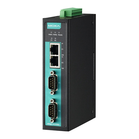
Серверы устройств NPort IA обеспечивают простое и надежное подключение последовательного порта к Ethernet для рынка промышленной автоматизации. Серверы поддерживают несколько режимов работы — TCP-сервер, TCP-клиент, UDP, Real COM, парное соединение и Ethernet-модем, — что обеспечивает совместимость сетевого программного обеспечения и является идеальным выбором для подключения последовательных устройств RS232/422/485, таких как ПЛК, датчики, счетчики, двигатели, приводы, считыватели штрих-кодов и дисплеи оператора. Серверы устройств NPort IA поставляются в компактном и прочном корпусе.
Корпус для монтажа на DIN-рейку.
ЗАМЕТКА Данное оборудование предназначено для использования в местах с ограниченным доступом.
Контрольный список пакетов
Перед установкой серверов устройств NPort IA убедитесь, что пакет содержит следующие элементы:
- 1 сервер устройств NPort серии IA
- Руководство по быстрой установке (печатное)
- Гарантийный талон
Опции
- DK-35A: комплект для монтажа на DIN-рейку (35 мм)
- Адаптер Mini DB9F-to-TB: переходник с гнезда DB9 на клеммную колодку
- DR-4524: блок питания 5 В постоянного тока на DIN-рейке 2 Вт/24 А с универсальным входом от 85 до 264 В переменного тока
- DR-75-24: блок питания 75 Вт/3.2 А на DIN-рейке 24 В постоянного тока с универсальным входом от 85 до 264 В переменного тока
- DR-120-24: 120 Вт/5 А, блок питания 24 В постоянного тока на DIN-рейке с входом от 88 до 132 В переменного тока/от 176 до 264 В переменного тока с помощью переключателя
Примечание: Сообщите своему торговому представителю, если что-либо из вышеперечисленного отсутствует или повреждено.
Внешний вид серии NPort IA5150

Внешний вид NPort IA5250

кнопка сброса— Нажмите кнопку сброса в течение 5 секунд, чтобы загрузить заводские настройки по умолчанию. Используйте заостренный предмет, например распрямленную скрепку или зубочистку, чтобы нажать кнопку сброса. Это приведет к тому, что светодиод Ready будет мигать и выключаться. Заводские настройки будут загружены после того, как индикатор готовности перестанет мигать (примерно через 5 секунд). В этот момент вы должны отпустить кнопку сброса.
Светодиодные индикаторы NPort IA (передняя панель)
| Имя и фамилия | Цвет | Функция |
| ПВР1, ПВР2 | Red | Питание подается на ввод питания PWR1, PWR2. |
| RDY | Red | Горит постоянно: питание включено, и NPort IA загружается. |
| Мигает: указывает на конфликт IP, сервер DHCP или BOOTP не ответил должным образом или произошел релейный выход. | ||
| Зелёная | Горит постоянно: питание включено, NPort IA работает нормально. | |
| Мигает: сервер устройств обнаружен с помощью функции местоположения администратора. | ||
| от | Питание отключено или возникла ошибка питания. | |
| Ethernet | Amber | Ethernet-соединение 10 Мбит/с. |
| Зелёная | Ethernet-соединение 100 Мбит/с. | |
| от | Кабель Ethernet отсоединен или имеет короткое замыкание. | |
| P1, P2 | Amber | Последовательный порт получает данные. |
| Зелёная | Последовательный порт передает данные. | |
| от | Данные не передаются и не принимаются через последовательный порт. | |
| FX | Amber | Горит постоянно: оптоволоконное соединение Ethernet, но порт свободен. |
| Мигает: оптоволоконный порт передает или принимает данные. |
Процедура установки оборудования
ШАГ 1: Подключите NPort IA к сети. Используйте стандартный прямой кабель Ethernet для подключения к концентратору или коммутатору. При настройке или тестировании NPort IA может оказаться удобным подключиться напрямую к Ethernet-порту вашего компьютера. В этом случае используйте перекрестный Ethernet-кабель.
ШАГ 2: Подключите последовательный порт NPort IA к последовательному устройству.
ШАГ 3: NPort IA предназначен для крепления на DIN-рейку или настенного монтажа. Два ползунка на задней панели NPort IA служат двойной цели. Для настенного монтажа оба ползунка должны быть выдвинуты. Для монтажа на DIN-рейку начните с того, что один ползунок вдвинут, а другой выдвинут. После прикрепления NPort IA к DIN-рейке нажмите на выдвинутый ползунок, чтобы зафиксировать сервер устройств на рейке. Два варианта размещения показаны на прилагаемых рисунках.
ШАГ 4: Подключите линию питания от 12 до 48 В постоянного тока к клеммной колодке NPort IA или подключите источник питания на DIN-рейке к клеммной колодке NPort IA.
Распиновка входа питания и выхода реле
 Монтаж на стене или в шкафу
Для крепления NPort IA5000 Series на стене требуется два винта. Головки винтов должны быть диаметром от 5 до 7 мм, стержни должны быть диаметром от 3 до 4 мм, а длина винтов должна быть более 10.5 мм.  ЗАМЕТКА Настенный монтаж сертифицирован для использования в морских условиях.
Информация об установке программного обеспечения
Для конфигурации NPort IP-адрес NPort по умолчанию:
локальная сеть: статическая; IP = 192.168.127.254; сетевая маска = 255.255.255.0.
ЗАМЕТКА Если вы забыли IP-адрес NPort, используйте утилиту поиска устройств (DSU) на своем ПК, чтобы найти NPort. После поиска в локальной сети устройств NPort DSU отобразит IP-адрес каждого устройства.
Вы можете войти в систему с паролем moxa, чтобы изменить любые настройки в соответствии с топологией вашей сети (например, IP-адрес) или последовательным устройством (например, параметры последовательного порта). При первом использовании щелкните Мастер на левой панели навигации. Мастер предложит вам настроить IP-адрес, SSID и режим безопасности. Для других настроек используйте заводские настройки по умолчанию или измените настройки для вашего приложения.
Для установки программного обеспечения загрузите соответствующие утилиты с веб-сайта Moxa. webсайт: https://www.moxa.com/support/support_home.aspx?isSearchShow=1
- Загрузите диспетчер драйверов NPort для Windows и установите его в качестве драйвера для работы с режимом Real COM серии NPort.
- Запустите NPort Windows Driver Manager; затем сопоставьте виртуальные COM-порты на вашей платформе Windows.
- Вы можете обратиться к разделу назначения контактов штекерных портов DB9, чтобы закольцевать контакты 2 и 3 для интерфейса RS-232, чтобы выполнить самопроверку устройства.
- Используйте HyperTerminal или аналогичную программу (вы можете скачать программу Moxa под названием PComm Lite), чтобы проверить, работает ли устройство.
Назначение контактов и разводка кабелей
Распиновка RS-232/422/485 (вилка DB9)
| PIN-код | RS-232 | RS-422/RS-485 (4 Вт) | RS-485 (2 Вт) |
| 1 | DCD | TxD-(А) | – |
| 2 | RXD | ТxД+(Б) | – |
| 3 | TXD | ПхД+(Б) | Данные+(Б) |
| 4 | DTR | RxD-(А) | Данные-(А) |
| 5 | GND | GND | GND |
| 6 | DSR | – | – |
| 7 | РТС | – | – |
| 8 | CTS | – | – |
| 9 | – | – | – |
4W/2W RS-485/RS-422 (клеммная колодка)

| PIN-код | RS-485 (2 Вт) | RS-422/RS-485 (4 Вт) |
| 1 | ТxД+(Б) | |
| 2 | TxD-(А) | |
| 3 | Данные+(Б) | ПхД+(Б) |
| 4 | Данные-(А) | RxD-(А) |
| 5 | GND |
В качестве дополнительных аксессуаров доступны четыре кабеля, которые можно использовать для подключения NPort IA к последовательным устройствам RS-232. Для вашего удобства мы показываем точные схемы разводки кабелей для каждого из двух кабелей.
Оптический интерфейс
| 100Base X | |||
| Многорежимный | Одиночный режим | ||
| Тип оптоволоконного кабеля | 0M1 | 50/125 вечера | G.652 |
| 800 МГц*км | |||
| Типичное расстояние | 4 км | 5 км | 40 км |
| Длина волны | Типичный (нм) | 1300 | 1310 |
| Диапазон TX (нм) | 1260 — 1360 | 1280 — 1340 | |
| Диапазон RX (нм) | 1100 — 1600 | 1100 — 1600 | |
| Оптический Питания |
Диапазон передачи (дБм) | От -10 до -20 | От 0 до -5 |
| Диапазон приема (дБм) | От -3 до -32 | От -3 до -34 | |
| Бюджет канала (дБ) | 12 | 29 | |
| Штраф за рассеивание (дБ) | 3 | 1 | |
| Примечание: При подключении одномодового оптоволоконного трансивера мы рекомендуем использовать аттенюатор, чтобы предотвратить повреждение, вызванное чрезмерной оптической мощностью. Примечание: Вычислите «типичное расстояние» конкретного оптоволоконного трансивера следующим образом: бюджет канала (дБ)> штрафа за дисперсию (дБ) + общие потери в канале (дБ). |
Женский DB9 в мужской DB9

Женский DB9 в мужской DB25

Характеристики
| Требования к питанию | |
| Потребляемая мощность | 12 в 48 постоянного тока |
| Потребляемая мощность (входная мощность) | • NPort IA-5150, NPort IA-5150-T, NPort IA-5250, NPort IA-5250-T: от 12 до 48 В постоянного тока, 435 мА (макс.) • NPort IA-5250I, NPort IA-5250I-T, NPort IA-5150-M-ST, NPort IA-5150-M-ST-T, MGate NPort IA-5150-M-SC, NPort IA-5150M-SC- Т: от 12 до 48 В постоянного тока, 510 мА (макс.) • NPort IA-5150I, NPort IA-5150I-T, NPort IA5150-S-SC, NPort IA-5150-S-SC-T, NPort IA-5150I-S-SC, NPort IA-5150I-S-SC-T , NPort IA-5150I-M-SC, NPort IA-5150I-MSC-T: от 12 до 48 В постоянного тока, 555 мА (макс.) |
| Рабочая Температура | от 0 до 60°C (от 32 до 140°F), от -40 до 75°C (от -40 до 167°F) для модели -T |
| Температура хранения | От -40 до 85 ° C (от -40 до 185 ° F) |
| Влажность при эксплуатации | 5 в 95% RH |
| Защита от магнитной изоляции (серийно) | 2 кВ (для моделей «I») |
| Размеры Без ушей: С вытянутыми ушами: |
29 x 89.2 x 118.5 мм (1.14 x 3.51 x 4.67 дюйма) 29 x 89.2 x 124.5 мм (1.14 x 3.51 x 4.9 дюйма) |
| Релейный выход | 1 цифровой релейный выход для сигнализации (нормально замкнутый): допустимая токовая нагрузка 1 А при 30 В постоянного тока |
| в опасных зонах | UL/cUL, класс 1, раздел 2, группа A/B/C/D, ATEX, зона 2, IECEx |
Информация ATEX и IECEx

NPort серии IA-5150/IA-5250
- Номер сертификата: DEMKO 18 ATEX 2168X
- Номер IECEx: IECEx UL 18.0149X
- Строка сертификации: Ex nA IIC T4 Gc
Диапазон температуры окружающей среды: 0°C ≤ Tamb ≤ 60°C (для суффикса без -T)
Диапазон окружающей среды: -40°C ≤ Tamb ≤ 75°C (для суффикса с -T) - Охватываемые стандарты:
ATEX: EN 60079-0:2012+A11:2013, EN 60079-15:2010
IECEx: IEC 60079-0, издание 6; МЭК 60079-15 Ред.4 - Условия безопасного использования:
• Оборудование должно использоваться только в зоне со степенью загрязнения не ниже 2, как определено в IEC/EN 60664-1.
• Оборудование должно быть установлено в корпусе, который обеспечивает минимальную степень защиты IP4 в соответствии с IEC/EN 60079-0.
• Проводники, подходящие для номинальной температуры кабеля ≥ 100°C
• Входной провод сечением 28–12 AWG (макс. 3.3 мм 2 ) для использования с устройствами.
NPort серии IA-5150I/IA-5250I
- Номер сертификата ATEX: DEMKO 19 ATEX 2232X
- Номер IECEx: IECEx UL 19.0058X
- Строка сертификации: Ex nA IIC T4 Gc
Диапазон температуры окружающей среды: 0°C ≤ Tamb ≤ 60°C (для суффикса без -T)
Диапазон окружающей среды: -40°C ≤ Tamb ≤ 75°C (для суффикса с -T) - Охватываемые стандарты:
ATEX: EN 60079-0:2012+A11:2013, EN 60079-15:2010
IECEx: IEC 60079-0, издание 6; МЭК 60079-15 Ред.4 - Условия безопасного использования:
• Оборудование должно использоваться только в зоне со степенью загрязнения не ниже 2, как определено в IEC/EN 60664-1.
• Оборудование должно быть установлено в корпусе, который обеспечивает минимальную степень защиты IP 54 в соответствии с IEC/EN 60079-0.
• Проводники, подходящие для номинальной температуры кабеля ≥ 100°C
• Входной провод сечением 28–12 AWG (макс. 3.3 мм 2 ) для использования с устройствами.
Адрес производителя: No. 1111, Heping Rd., Bade Dist., Taoyuan City 334004, Тайвань.
Документы / Ресурсы
-
Contents
-
Table of Contents
-
Bookmarks
Quick Links
NPort IA5150A/IA5250A Series
User’s Manual
Second Edition, December 2012
www.moxa.com/product
© 2012 Moxa Inc. All rights reserved.
Reproduction without permission is prohibited.
Related Manuals for Moxa Technologies NPort IA5150A
Summary of Contents for Moxa Technologies NPort IA5150A
-
Page 1
NPort IA5150A/IA5250A Series User’s Manual Second Edition, December 2012 www.moxa.com/product © 2012 Moxa Inc. All rights reserved. Reproduction without permission is prohibited. -
Page 2: Copyright Notice
NPort IA5150A/IA5250A Series User’s Manual The software described in this manual is furnished under a license agreement and may be used only in accordance with the terms of that agreement. Copyright Notice Copyright ©2012 Moxa Inc. All rights reserved. Reproduction without permission is prohibited.
-
Page 3: Table Of Contents
Table of Contents Introduction ……………………….1-1 Overview ……………………….1-2 Package Checklist ……………………..1-2 Product Features ……………………..1-2 Product Specifications ……………………. 1-3 Getting Started……………………..2-1 Panel Layout ……………………….2-2 Connecting the Hardware……………………2-3 Wiring Requirements ……………………2-3 Connecting the Power ……………………2-3 Connecting to the Network ………………….
-
Page 4
Port Pinout Diagrams …………………….. A-2 Ethernet Port Pinouts ……………………A-2 RS-232/422/485 (male DB9) Pinouts ………………… A-2 RS-422/485 (5-contact terminal block) Pinouts for the NPort IA5150A Series ……..A-2 Power Input and Relay Output Pinouts ………………. A-2 Serial Cable Wiring Diagrams ………………….. A-3 Female DB9 to Male DB9 …………………. -
Page 5: Introduction
Introduction Welcome to the NPort IA5150A/IA5250A Series of industrial serial device servers. In this manual, we refer to the eight products in the series collectively as the “NPort IA5150A/IA5250A Series.” The four models in the NPort IA5150A/IA5250A Series are: NPort IA5150A 1-port RS-232/422/485 industrial automation device server with serial/LAN/power surge protection, two 10/100BaseT(X) ports (1 IP), 0 to 60°C operating temperature…
-
Page 6: Overview
Not only has the hardware been upgraded, but more flexible and user-friendly software has been added. The NPort IA5150A/IA5250A series of device servers deliver easy and reliable serial-to-Ethernet connectivity for the industrial automation market. The NPort IA5150A/IA5250A series is designed to allow any serial device to connect to an Ethernet network.
-
Page 7: Product Specifications
NPort IA5150A/IA5250A Series Introduction Product Specifications Ethernet Interface Number of Ports: 2 Speed: 10/100 Mbps, auto MDI/MDIX Connector: 8-pin RJ45 Magnetic Isolation Protection: 1.5 KV built-in Serial Interface Number of Ports: NPort® IA5150A: 1 NPort® IA5250A: 2 Serial Standards: RS-232/422/485 Connector: NPort®…
-
Page 8: Regulatory Approvals
NPort IA5150A/IA5250A Series Introduction Input Voltage: 12 to 48 VDC Power Consumption: NPort® IA5150A: 12 to 48 VDC, 220 mA @ 12 VDC; 110 mA @ 24 VDC NPort® IA5150AI: 12 to 48 VDC, 255 mA @ 12 VDC; 130 mA @ 24 VDC NPort®…
-
Page 9: Getting Started
Getting Started In this chapter, we give instructions on installing the NPort IA5150A/IA5250A device servers. Software installation is covered in subsequent chapters. The following topics are covered in this chapter: Panel Layout Connecting the Hardware Wiring Requirements …
-
Page 10: Panel Layout
NPort IA5150A/IA5250A Series Getting Started Panel Layout NPort IA5150A Series NPort IA 5250A…
-
Page 11: Connecting The Hardware
Connecting the Power Connect the 12-48 VDC power line with the NPort IA5150A/IA5250A’s terminal block. If the power is properly supplied, the “Ready” LED will show a solid red color until the system is ready, at which time the “Ready” LED will change to a green color.
-
Page 12: Connecting To The Network
The Ethernet LED will flash when Ethernet packets are being transmitted or received. ATTENTION Every NPort IA5150A/ IA5250A series is equipped with 2 Ethernet ports, which can be used to create an open chain of NPort IA5150A/IA5250A device servers. You must be careful not to connect the Ethernet ports of the two device servers at the ends of the chain.
-
Page 13: Adjust The Pull-High/Pull-Low Resistors And Terminators For Rs-422/Rs-485 Ports
It is improbable for a single pull high/low resistor value to suit all the various environments and this is why the NPort IA5150A/IA5250A series provides DIP switches for setting the pull high/low resistor values for each serial port.
-
Page 14: Initial Ip Address Configuration
Initial IP Address Configuration When setting up your NPort IA5150A/IA5250A for the first time, the first thing you should do is configure the IP address. This chapter introduces the methods that can be used to configure the device server’s IP address.
-
Page 15: Initializing The Nport’s Ip Address
IP address will be reconfigured. ATTENTION In order to use this setup method, both your computer and NPort IA5150A/IA5250A must be connected to the same LAN. Or, you may use a cross-over Ethernet cable to connect the NPort IA5150A/IA5250A directly to your computer’s Ethernet card.
-
Page 16: Telnet Console
4. arp –s 192.168.200.100 00-90-E8-xx-xx-xx 5. This is where 192.168.200.100 is the new IP address and 00-90-E8-xx-xx-xx is the MAC address for your NPort IA5150A/IA5250A. (Be sure to use the actual IP address and MAC address for your NPort IA5150A/IA5250A.) 6.
-
Page 17
NPort IA5150A/IA5250A Series Initial IP Address Configuration 4. Type 2 to select Network settings, and then press Enter. 5. Type 1 to select IP address and then press Enter. 6. Use the Backspace key to erase the current IP address, type in the new IP address, and then press Enter. -
Page 18
NPort IA5150A/IA5250A Series Initial IP Address Configuration 7. Press any key to continue… 8. Type m and then press Enter to return to the main menu. 9. Type s and then press Enter to Save/Restart the system. -
Page 19: Serial Console (19200, N, 8, 1)
Serial Console (19200, n, 8, 1) You may use the RS-232 console port to set up the IP address for the NPort IA5150A/IA5250A. We suggest using PComm Terminal Emulator, which is available free of charge as part of the PComm Lite program suite, to carry out the installation procedure, although other similar utilities may also be used.
-
Page 20
7. NPort IA5150A/IA5250A will automatically switch from data mode to console mode as it receives a continuous string of “ ` ”. 8. Input the password when prompted. Note that this page will only appear when the NPort IA5150A/IA5250A has been set up for password protection. -
Page 21
NPort IA5150A/IA5250A Series Initial IP Address Configuration 9. Start configuring the IP address under Network Settings. Refer to step 4 in the Telnet Console section for the rest of the IP settings. -
Page 22: Choosing The Proper Operation Mode
Choosing the Proper Operation Mode In this chapter, we describe the NPort IA5150A/IA5250A various Toperation modes. The options include an operation mode that uses a driver installed on the host computer, and operation modes that rely on TCP/IP socket programming concepts. After choosing the proper operation mode in this chapter, refer to Chapter 5 for detailed configuration parameter definitions.
-
Page 23: Overview
The NPort IA5150A/IA5250A is an external IP-based network device that allows you to expand the number of serial ports for a host computer on demand. As long as your host computer supports the TCP/IP protocol, you won’t be limited by the host computer’s bus limitation (such as ISA or PCI), or lack of drivers for various…
-
Page 24: Rfc2217 Mode
RFC2217 mode is similar to Real COM mode in that a driver is used to establish a transparent connection between a host computer and a serial device by mapping the serial port on the NPort IA5150A/IA5250A to a local COM port on the host computer. RFC2217 defines general COM port control options based on the Telnet protocol.
-
Page 25: Udp Mode
Pair Connection Mode Pair Connection Mode employs two NPort IA5150A/IA5250A units in tandem, and can be used to remove the 15-meter distance limitation imposed by the RS-232 interface. One NPort IA5150A/IA5250A is connected from its RS-232 port to the COM port of a PC or other type of computer, such as a hand-held PDA, and the serial device is connected to the RS-232 port of the other NPort IA5150A/IA5250A.
-
Page 26: Disabled Mode
NPort IA5150A/IA5250A Series Choosing the Proper Operation Mode Console management is commonly used by connecting to Console/AUX or COM ports of routers, switches, and UPS units. Rtelnet works the same as RAW mode in that only one TCP port is listened to after booting up. The system then waits for a host on the network to initiate a connection.
-
Page 27: Web Console Configuration
Web Console Configuration The Web Console is the most user-friendly method available to configure the NPort IA5150A/IA5250A. In this chapter, we will introduce the Web Console function groups and function definitions. The following topics are covered in this chapter: Opening Your Browser …
-
Page 28: Opening Your Browser
The examples shown in this chapter use the factory default IP address (192.168.127.254). 1. The NPort IA5150A/IA5250A homepage will appear. There are two buttons on this page: Quick Setup and Export/Import. You can click Overview at any time to go back to this page.
-
Page 29
“Basic Settings,” “Network Settings,” “Serial Settings,” and “Operating Settings,” sections in this chapter. 1. In Step 1/3, you must assign a valid IP address to the NPort IA5150A/IA5250A before the NPort can start operating within your network. Your network system administrator should provide you with an IP address and related settings for your network. -
Page 30
NPort IA5150A/IA5250A Series Web Console Configuration Operating Settings to select suitable settings. 3. In the Step 3/3, you can modify the serial settings. 4. Review your settings on the Finish Settings page. If you are sure they are correct, then click the Save/Restart button to restart the device with these new settings. -
Page 31: Export/Import
The Disable option for “Web console” and “Telnet console” is included for security reasons. In some cases, you may want to disable one or both of these console utilities as an extra precaution to prevent unauthorized users from accessing your NPort IA5150A/IA5250A. The factory default for both “Web console” and “Telnet console is Enable.
-
Page 32: Network Settings
«Reset to default» button will be automatically disabled and will no longer work. Network Settings You must assign a valid IP address to the NPort IA5150A/IA5250A before the NPort can start operating within your network. Your network system administrator should provide you with an IP address and related settings for your network.
-
Page 33
A subnet mask represents all the network hosts at one geographic location, such as all the hosts in a building or on the same local area network. When a packet is sent out over the network, the NPort IA5150A/IA5250A will use the subnet mask to check whether the desired TCP/IP host specified in the packet is on the local network segment. -
Page 34: Snmp Settings
DNS server; DNS Server 2 is included for use when DNS sever 1 is unavailable. The NPort IA5150A/IA5250A acts as a DNS client by actively querying the DNS server for the IP address that is associated with a particular domain name. NPort IA5150A/IA5250A functions that support domain name are Time server, Destination IP Address in TCP Client mode, Mail Server, SNMP trap server, and Auto report to IP.
-
Page 35: Serial Settings
NPort IA5150A/IA5250A Series Web Console Configuration Auto report to IP Setting Factory Default Necessity E.g., 192.168.1.1 or None Optional (IP addresses in the form of x.x.x.0 and x.x.x.255 are invalid.) Reports generated by the Auto report function will be automatically sent to this IP address.
-
Page 36: Serial Parameters
Necessity Enable, Disable Enable Required The NPort IA5150A/IA5250A’s serial ports provide a 16-byte FIFO in the Tx and Rx directions. To prevent unexpected communication, disable the FIFO setting if your serial device does not offer FIFO. Interface Setting Factory Default…
-
Page 37: Operating Settings
0 min: TCP connection is not closed due to an idle TCP connection. 1 to 99 min: the NPort IA5150A/IA5250A will automatically close the TCP connection if there is no TCP activity during this given time. After the connection has closed, the NPort IA5150A/IA5250A will start “listening” for another Real COM driver connection from another host.
-
Page 38
Max connection is usually used when the user needs to receive data from different hosts simultaneously. The factory default is 1, this means that only one specific host can access this NPort IA5150A/IA5250A, and the Real COM driver on that host will have full control over the port. -
Page 39
IA5150A/IA5250A should send that series of characters during a time interval that is less than the Force transmit timeout of the NPort IA5150A/IA5250A, and the total length of data must be less than or equal to the NPort IA5150A/IA5250A’s internal buffer size. The serial communication buffer size for the NPort IA5150A/IA5250A is 1 KB per port. -
Page 40: Rfc2217 Mode
4001 Required The “Local TCP port” is the TCP port that the NPort IA5150A/IA5250A uses to listen to connections, and that other devices must use to contact the NPort IA5150A/IA5250A. To avoid conflicts with well known TCP ports, the default is set to 4001.
-
Page 41
IA5150A/IA5250A should send that series of characters during a time interval that is less than the Force transmit timeout for the NPort IA5150A/IA5250A, and the total length of data must be less than or equal to the NPort IA5150A/IA5250A’s internal buffer size. The serial communication buffer size for the NPort IA5150A/IA5250A is 1 KB per port. -
Page 42: Tcp Server Mode
0 min: TCP connection is not closed due to an idle TCP connection. 1 to 99 min: The NPort IA5150A/IA5250A will automatically close the TCP connection if there is no TCP activity during this given time. After the connection has closed, the NPort IA5150A/IA5250A will start “listening” for another host’s TCP connection.
-
Page 43
Max connection 2 to 8: Allows two to eight host’s TCP connection request to open this NPort IA5150A/IA5250A serial port, at the same time. When multiple hosts establish a TCP connection to the specific serial port at the same time, NPort IA5150A/IA5250A will duplicate the serial data and transmit it to all of the hosts. -
Page 44
IA5150A/IA5250A should send that series of characters during a time interval that is less than the Force transmit timeout for the NPort IA5150A/IA5250A, and the total length of data must be less than or equal to the NPort IA5150A/IA5250A’s internal buffer size. The serial communication buffer size for NPort IA5150A/IA5250A is 1 KB per port. -
Page 45: Tcp Client Mode
7 min Optional 0 min: TCP connection is not closed due to an idle TCP connection. 1 to 99 min: The NPort IA5150A/IA5250A automatically closes the TCP connection if there is no TCP activity during this given time. Inactivity time…
-
Page 46
Delimiter 2 is optional. If left blank, then Delimiter 1 alone trips clearing of the buffer. If the size of the serial data received is greater than 1 KB, the NPort IA5150A/IA5250A will automatically pack the data and send it to the Ethernet. -
Page 47
Required Name (E.g., 192.168.1.1) Allows NPort IA5150A/IA5250A to connect actively to the remote host whose IP address is set by this parameter. ATTENTION Up to 4 connections can be established between the NPort IA5450A and hosts. The connection speed or throughput may be low if one of the four connections is slow, since one slow connection will slow down the other connections. -
Page 48
NPort IA5150A/IA5250A Series Web Console Configuration ATTENTION The Destination IP address parameter can use both IP address and Domain Name. For some applications, the user may need to send the data actively to the remote destination domain name. Designated Local Port 1/2/3/4… -
Page 49: Udp Mode
Delimiter 2 is optional. If left blank, then Delimiter 1 alone trips clearing of the buffer. If the size of the serial data received is greater than 1 KB, the NPort IA5150A/IA5250A will automatically pack the data and send it to the Ethernet.
-
Page 50
Factory Default Necessity 1 to 65535 4001 Required The UDP port that NPort IA5150A/IA5250A listens to, and that other devices must use to contact NPort IA5150A/IA5250A. To avoid conflicts with well known UDP ports, the default is set to 4001. 5-24… -
Page 51: Pair Connection Mode
0 to 99 min 7 min Required 0 min: TCP connection is not closed due to an idle TCP connection. 1 to 99 min: The NPort IA5150A/IA5250A closes the TCP connection automatically if there is no TCP activity for the given time. 5-25…
-
Page 52: Ethernet Modem Mode
7 min Required 0 min: TCP connection is not closed due to an idle TCP connection. 1 to 99 min: The NPort IA5150A/IA5250A closes the TCP connection automatically if there is no TCP activity for the given time. Local TCP port…
-
Page 53
Disconnection request from local site When the NPort IA5150A/IA5250A is in data mode, the user can drive the DTR signal to OFF, or send “+++” from the local serial port to the NPort IA5150A/IA5250A. The NPort IA5150A/IA5250A will enter command mode and return “NO CARRIER”… -
Page 54
Required 0 min: The TCP connection will not be closed due to an idle TCP connection. 1 to 99 min: The NPort IA5150A/IA5250A closes the TCP connection automatically if there is no TCP activity for the given time. Local TCP port… -
Page 55: Reverse Telnet Mode
Optional 0 min: The TCP connection will not be closed due to an idle TCP connection. 1 to 99 min: The NPort IA5150A/IA5250A automatically closes the TCP connection if there is no TCP activity for the given time. Inactivity time…
-
Page 56: Disabled Mode
Accessible IP Settings allows you to add or block remote host IP addresses to prevent unauthorized access. Access to the NPort IA5150A/IA5250A is controlled by IP address. That is, if a host’s IP address is in the accessible IP table, then the host will be allowed to access the the NPort IA5150A/IA5250A. You can allow one of the following cases by setting the parameter.
-
Page 57: Auto Warning Settings
NPort IA5150A/IA5250A Series Web Console Configuration Allowable Hosts Input format Any host Disable 192.168.1.120 192.168.1.120 / 255.255.255.255 192.168.1.1 to 192.168.1.254 192.168.1.0 / 255.255.255.0 192.168.0.1 to 192.168.255.254 192.168.0.0 / 255.255.0.0 192.168.1.1 to 192.168.1.126 192.168.1.0 / 255.255.255.128 192.168.1.129 to 192.168.1.254 192.168.1.128 / 255.255.255.128…
-
Page 58: Event Type
Cold start This refers to starting the system from power off (contrast this with warm start). When performing a cold start, the NPort IA5150A/IA5250A will automatically issue an Auto warning message by e-mail, or send an SNMP trap after booting up.
-
Page 59
IA5150A/IA5250A will send an e-mail with the password changed notice before the NPort IA5150A/IA5250A reboots. If the the NPort IA5150A/IA5250A is unable to send an e-mail message to the mail server within 15 seconds, the NPort IA5150A/IA5250A will reboot anyway, and abort the e-mail auto warning. -
Page 60: Upgrade Firmware
To configure this feature, click the Event Type Trap checkbox. Upgrade Firmware Keep your NPort IA5150A/IA5250A up to date with the latest firmware from Moxa. Occasionally, compare your NPort firmware to the version currently available at the Moxa website (www.moxa.com), If there is a new firmware version, you can download it and click Import to upgrade your firmware.
-
Page 61: Monitor Async
NPort IA5150A/IA5250A Series Web Console Configuration Monitor Async Click Async under Monitor to show the current status of the serial port. Monitor Async-Settings Click Async Setting under Monitor to show the run-time settings for the serial port. 5-35…
-
Page 62: Monitor Relay Output
If the password is erased, then NPort IA5150A/IA5250A will not have password protection. ATTENTION If you forget the password, the ONLY way to configure NPort IA5150A/IA5250A is by using the «Reset to default» button on NPort IA5150A/IA5250A’s top side to “Load Factory Default.”…
-
Page 63: Load Factory Default
NPort IA5150A/IA5250A Series Web Console Configuration Load Factory Default This function will reset all of NPort IA5150A/IA5250A’s settings to the factory default values. Be aware that previous settings will be lost. Save/Restart Click Save/Restart will save the current configured settings and restart NPort IA5150A/IA5250A to take effect.
-
Page 64: Configuring Nport Administrator
The following topics are covered in this chapter: Overview Installing NPort Administrator Configuration Broadcast Search Unlock Password Protection Configuring the NPort IA5150A/IA5250A Upgrading the Firmware Export Configuration Import Configuration Monitor Port Monitor …
-
Page 65: Overview
Configuring NPort Administrator Overview NPort Administrator lets you install and configure your NPort IA5150A/IA5250A Series products easily over the network. Five function groups are provided to ease the installation process, allow off-line COM mapping, and provide monitoring and IP location server functions.
-
Page 66
NPort IA5150A/IA5250A Series Configuring NPort Administrator 4. Click Install to proceed with the installation. 5. The Installing window reports the progress of the installation. 6. Click Next to proceed with the installation. 7. Click Finish to complete the installation of NPort Administration Suite. -
Page 67: Configuration
LAN as your computer. Since the Broadcast Search function searches by MAC address and not IP address, all NPort IA5150A/IA5250As connected to the LAN will be located, regardless of whether or not they are part of the same subnet as the host.
-
Page 68: Unlock Password Protection
In this case, proceed as follows to “Unlock” the device server. 1. Select the NPort IA5150A/IA5250A with “Lock” status, click the right mouse button, and then select Unlock.
-
Page 69: Configuring The Nport Ia5150A/Ia5250A
The NPort IA5150A/IA5250A is not password protected, and “Broadcast Search” was used to locate it. Fixed The NPort IA5150A/IA5250A is not password protected, and “Search by IP address” was used to locate it. Lock Fixed The NPort IA5150A/IA5250A is password protected, “Specify by IP address” was used to locate it, and the password has not yet been entered from within the current Administrator session.
-
Page 70: Upgrading The Firmware
NPort IA5150A/IA5250A Series Configuring NPort Administrator 2. Unlock the NPort IA5150A/IA5250A you wish to configure if it is password protected. Right click the NPort IA5150A/IA5250A and select Configure to start the configuration. 3. The progress bar shows that Administrator is retrieving configuration information from the specific NPort IA5150A/IA5250A.
-
Page 71: Export Configuration
NPort IA5150A/IA5250A Series Configuring NPort Administrator 2. Unlock the NPort IA5150A/IA5250A you wish to configure if it is password protected. Right click a specific NPort IA5150A/IA5250A and select the Upgrade Firmware function to start upgrading the firmware. 3. Select the correct ROM file to download.
-
Page 72: Import Configuration
The Import Configuration function is used to import an NPort IA5150A/IA5250A configuration from a file into one or more of the same model NPort IA5150A/IA5250A. To import a configuration, first select the target servers, click the right mouse button, and then select Import Configuration. Follow the onscreen instructions to locate the configuration file and start downloading the file.
-
Page 73
In the second case, you must enter the path to the WAV file that you want to be played. “New event” means that one of the NPort IA5150A/IA5250As in the monitor is “Alive” or “Not… -
Page 74
10. When one of the NPort IA5150A/IA5250As loses connection with the Monitor program, a warning alert will display automatically. The warning music will be played at the same time. 11. In the Monitor screen, you can see that the NPort IA5150A/IA5250As that are “Not Alive” are shown in red color. -
Page 75: Port Monitor
Windows Administration Suite comes with Windows Real COM drivers. After you install NPort Administration Suite, there are two ways to set up the NPort IA5150A/IA5250A serial port as your host’s remote COM port. The first way is with On-line COM Mapping. On-line COM Mapping will check to make sure that the NPort IA5150A/IA5250A is connected correctly to the network and then install the driver on the host computer.
-
Page 76: On-Line Com Mapping
Connect NPort IA5150A/IA5250A to the network Set NPort IA5150A/IA5250A to the proper IP address Map COMs to your host Apply Change. 2. Off-line COM Mapping: Map COMs to your host Apply Change Connect the NPort IA5150A/IA5250A to the network Configure NPort IA5150A/IA5250A’s IP address. On-line COM Mapping 1.
-
Page 77
Under classical mode, the driver will not notify the user’s program that Tx is completed until all Tx data has been sent out from the NPort IA5150A/IA5250A; this mode will cause lower throughput. If you want to ensure that all data is sent out before further processing, classical mode is recommended. -
Page 78
NPort IA5150A/IA5250A Series Configuring NPort Administrator 7. The Serial Parameter settings shown here are the default settings when the NPort IA5150A/IA5250A is powered on. However, the program can redefine the serial parameters to different values after the program opens the port via API. -
Page 79: Off-Line Com Mapping
Off-line COM Mapping 1. Add a target by inputting the IP address and selecting the Model Name without physically connecting the NPort IA5150A/IA5250A to the network. 2. Modify the port settings as needed. 3. Right click in the NPort list section and select Apply Change.
-
Page 80: Com Grouping
NPort IA5150A/IA5250A Series Configuring NPort Administrator COM Grouping The “COM Grouping” function is designed to simulate the multi-drop behavior of serial communication over an Ethernet network. COM Grouping allows you to create a COM Group and redirect data from it to several physical COM ports on NPort device servers.
-
Page 81
NPort IA5150A/IA5250A Series Configuring NPort Administrator ATTENTION The COM Grouping function only supports Windows NT, 2000, and later. The maximum number of ports for each group is 32. 3. Select the Grouping selected port(s) together checkbox. 4. On the COM Grouping page, you can set “Read” and “Write” permissions for every serial port. It is necessary to set Signal Status in order to control the data transmission with specified control signals (e.g.,… -
Page 82: Deleting A Com Group
NPort IA5150A/IA5250A Series Configuring NPort Administrator 5. Click OK, and confirm that the serial ports that were assigned. The COM Port column confirms that your selected ports are labeled as part of a “Group.” You will be able to view the serial ports that were assigned to and removed from the Group.
-
Page 83
NPort IA5150A/IA5250A Series Configuring NPort Administrator 2. Select a COM number for this COM group and check the Auto enumerating COM number for selected ports to use the COM number you select as the first starting COM number, and then click OK. -
Page 84: Adding A Port To A Com Group
NPort IA5150A/IA5250A Series Configuring NPort Administrator Adding a Port to a COM Group Follow the steps below to add a serial port into an existing COM Group: 1. Select the serial port that you are adding and right-click to select COM Settings.
-
Page 85: Removing A Port From A Com Group
NPort IA5150A/IA5250A Series Configuring NPort Administrator 3. You will be able to view the serial ports that were assigned to and removed from the Group. Click Apply to apply the settings. 4. Finally, click Yes to confirm. Removing a Port from a COM Group Follow the steps below to remove a serial port from a COM Group: 1.
-
Page 86
NPort IA5150A/IA5250A Series Configuring NPort Administrator 2. Select a COM number that is not in use or assigned to a Group and click OK. 3. You will be able to view the serial ports that were assigned to and removed from the Group. Click Apply to apply the settings. -
Page 87: Modify Ports In A Com Group
NPort IA5150A/IA5250A Series Configuring NPort Administrator Modify Ports in a COM Group In the following subsections we examine three ways in which the serial ports in a COM Group can be modified: Changing the COM Number of a COM Group 1.
-
Page 88
NPort IA5150A/IA5250A Series Configuring NPort Administrator 3. Select the Grouping selected port(s) together checkbox and then click OK. 4. You will be able to view the serial ports that were assigned to and removed from the Group. Click Apply to apply the settings. -
Page 89: Changing Advanced Settings And Serial Parameters Of The Com Group
NPort IA5150A/IA5250A Series Configuring NPort Administrator Changing Advanced Settings and Serial Parameters of the COM Group 1. Check the port specified on the COM Grouping page as the signal port. 2. Select the ”Signal Status” controlled port and then right-click and select COM Settings.
-
Page 90
NPort IA5150A/IA5250A Series Configuring NPort Administrator 3. The Advanced Settings and Serial Parameters pages will be available for modification. 6-27… -
Page 91: Changing The Serial Port Specified As Signal Port For The Com Group
NPort IA5150A/IA5250A Series Configuring NPort Administrator Changing the Serial Port Specified as Signal Port for the COM Group 1. Selecta serial port in the Group and then right-click and select COM Settings. 2. Check the Grouping selected port(s) together check box.
-
Page 92: Ip Address Report
COM Group and change the Read/Write status for each serial port. IP Address Report When NPort IA5150A/IA5250A is used in a dynamic IP environment, users must spend more time with IP management tasks. NPort IA5150A/IA5250A Series products help out by periodically reporting their IP address to the IP location server, in case the dynamic IP has changed.
-
Page 93
Configuring NPort Administrator 2. Select the IP Address Report, and click the right mouse button to select Settings. 3. Configure the Local Listen Port to be the same as the NPort IA5150A/IA5250A’s “Auto report to UDP port” setting. 4. Click Go to start receiving the Auto IP address report from the NPort IA5150A/IA5250A. -
Page 94: Ip Serial Lib
IP Serial LIB The following topics are covered in this chapter: Overview IP Serial LIB Function Groups Example Program…
-
Page 95: Overview
(such as RFC2217), IP Serial Library uses a command port to communicate with the NPort IA5150A/IA5250A in user’s program. IP Serial Library not only runs with excellent efficiency but also runs without any decode or encode problems.
-
Page 96: Example Program
NPort IA5150A/IA5250A Series IP Serial LIB Example Program char NPortip=”192.168.1.10”; char buffer[255]; /*data buffer, 255 chars */ int port = 1; /*1st port */ int portid; /* port handle */ nsio_init(); /*initial IP Serial Library */ /*1st port, NPort IP=192.168.1.10 */ portid = nsio_open(NPortip, port);…
-
Page 97: Pinouts And Cable Wiring
Port Pinout Diagrams Ethernet Port Pinouts RS-232/422/485 (male DB9) Pinouts RS-422/485 (5-contact terminal block) Pinouts for the NPort IA5150A Series Power Input and Relay Output Pinouts Serial Cable Wiring Diagrams Female DB9 to Male DB9 …
-
Page 98: Port Pinout Diagrams
– – – – – – – – – Note: The NPort IA5150A Series’s DB9 ports only support RS-232 signals. RS-422/485 (5-contact terminal block) Pinouts for the NPort IA5150A Series 2-wire RS-485 RS-422, 4-wire RS-485 – TxD+(B) – TxD-(A) Data+(B)
-
Page 99: Serial Cable Wiring Diagrams
NPort IA5150A/IA5250A Series Pinouts and Cable Wiring Serial Cable Wiring Diagrams Female DB9 to Male DB9 Female DB9 to Male DB25…
-
Page 100: Ethernet Cables
NPort IA5150A/IA5250A Series Pinouts and Cable Wiring Ethernet Cables…
-
Page 101: Well Known Port Numbers
Well Known Port Numbers In this appendix, which is included for your reference, we provide a list of Well Known port numbers that may cause network problems if you set the NPort IA5450A to one of these ports. Refer to RFC 1700 for Well Known port numbers, or refer to the following introduction from the IANA.
-
Page 102
NPort IA5150A/IA5250A Series Well Known Port Numbers UDP Socket Application Service reserved Management Utility Echo Discard Active Users (systat) Daytime Any private printer server Resource Location Protocol Host name server (names server) Whois (nickname) (Login Host Protocol) (Login) Domain Name Server (domain) -
Page 103: Snmp Agents With Mib Ii & Rs-232 Like Groups
SNMP Agents with MIB II & RS-232 Like Groups The NPort IA5450A has SNMP (Simple Network Management Protocol) agent software built in. It supports SNMP Trap, RFC1317 RS-232 like groups and RFC 1213 MIB-II. The following table lists the standard MIB-II group, as well as the variable implementation for the NPort IA5450A.
-
Page 104
NPort IA5150A/IA5250A Series SNMP Agents with MIB II & RS-232 Like Groups UDP MIB TCP MIB SNMP MIB UdpInDatagrams tcpRtoAlgorithm snmpInPkts UdpNoPorts tcpRtoMin snmpOutPkts UdpInErrors tcpRtoMax snmpInBadVersions UdpOutDatagrams tcpMaxConn snmpInBadCommunityNames UdpLocalAddress tcpActiveOpens snmpInASNParseErrs UdpLocalPort tcpPassiveOpens snmpInTooBigs tcpAttempFails snmpInNoSuchNames Address Translation MIB… -
Page 105: Rfc1317: Rs-232 Mib Objects
NPort IA5150A/IA5250A Series SNMP Agents with MIB II & RS-232 Like Groups RFC1317: RS-232 MIB Objects Generic RS-232-like Group RS-232-like General Port Table RS-232-like Asynchronous Port Group rs232Number rs232PortTable rs232AsyncPortTable rs232PortEntry rs232AsyncPortEntry rs232PortIndex rs232AsyncPortIndex rs232PortType rs232AsyncPortBits rs232PortInSigNumber rs232AsyncPortStopBits rs232PortOutSigNumber rs232AsyncPortParity…
-
Page 106: Auto Ip Report Protocol
Auto IP Report Protocol NPort device servers provide several ways to configure Ethernet IP addresses. One of them is DHCP Client. When you set up the NPort to use DHCP Client to configure Ethernet IP addresses, it will automatically send a DHCP request over the Ethernet to find the DHCP Server.
-
Page 107
NPort IA5150A/IA5250A Series Auto IP Report Protocol ID List ID Value Description Length Note Server Name Variable ASCII char Hardware ID Little-endian MAC Address 6 bytes MAC address. If the MAC address is “00-90-E8-01-02-03”, the MAC [0] is 0, MAC[1] is 0x90(hex), MAC[2] is 0xE8(hex), and so on. -
Page 108: Compliance Notice
Compliance Notice CE Warning This is a Class A product. In a domestic environment, this product may cause radio interference in which case the user may be required to take appropriate measures. Federal Communications Commission Statement FCC — This device complies with part 15 of the FCC Rules. Operation is subject to the following two conditions: (1) This device may not cause harmful interference, and (2) this device must accept any interference received, including interference that may cause undesired operation.