


|
2.2 Меры безопасности при работе Запрещается:
|
||||

Multiplaz 3500
Portable Plasma System
Operating Manual
Please read this manual prior to operating the system and
keep it for future reference.
Мultiplaz 3500
2
Legend
- “Caution”
- “Prohibited”
International Standards Certificate of Conformity U1 2792095 01
Manufacturer: Multiplaz TECHNOLOGY (SHENZHEN) CO., LTD
Address: 5/F, Building C3, Heng Feng Industrial Park,
He Zhou, Bao An, ShenZhen, China, 518126
Product: Multiplaz-3500
This is to certify that the above product is compliant with the following directives and
standards:
Low Voltage Directive: 2006/95/EC
Arc Welding Equipment - Part 1: Welding Power Sources. IEC/EN 60974-1:2005
Arc Welding Equipment - Part 7: Torches. IEC/EN 60974-7:2005
Arc Welding Equipment - Part 10: Electromagnetic Compatibility (EMC) Requirements.
IEC/EN 60974-10:2005
3
4
Introduction
Compliance
Manufacturer’s Undertakings
Storage, Transportation, and Operating Conditions
Application, Specifications
What’s Included
1
2
Safety
Workstation Equipment
Operating Safety Precautions
Specifications and Operating Principle
Torch
Torch Operating Principle
Power Supply
Controls
3
Cutting
Setup
Indirect Arc Cutting
Direct Arc Cutting
Operation Closeout
4
Welding, Brazing, Braze Welding, and Soldering
Setup
Indirect Arc Welding
Direct Arc Welding
Soldering, Brazing, and Braze Welding
Operation Closeout
System Maintenance
Power Supply Maintenance
Torch Maintenance
Torch Disassembly
Torch Assembly
Questions and Answers
Troubleshooting Techniques
Process Attachment
5
5
6
7
8
6
1. Introduction
1
Congratulations on an excellent buy you have purchased a unique plasma system, the MULTIPLAZ-3500!
1.1 Compliance
- System is compliant with the IEC/EN 60974-1, 60974-7 standards requirements
1.2 Manufacturer’s Undertakings
Warranty: 24 months from date of sale provided the seal is undamaged, there is no
exterior damage and storage, transportation and operating requirements are complied
with. Repairs under warranty are performed by the authorized dealer on presentation of
the warranty. Repairs under warranty will be performed if the system has been properly
maintained.
Caution!
- The useful life of the system is 10 years if the operating and maintenance procedures
are followed.
1.3 Storage, Transportation, and Operating Conditions.
Prior to putting into operation, the system should be stored indoors in manufacturer’s
packaging at temperatures of between -50С and +50С and a relative humidity of 98% at
25С. After putting into operation, the system shall be stored indoors at temperatures of
above 0С. The system may be stored at -50С provided the torches are dry.
Prior to putting into operation, the system must be transported in original packaging at
temperatures of between -50С and +50С, a relative humidity of up to 98% at 25С, and
an atmospheric pressure in excess of 12 kPa. The system must be protected from direct
effects of precipitation.
The system should be operated indoors or in an open shed at an ambient temperature
of between -10С and +40С, an average monthly relative humidity of up to 90% at +20С,
up to 80% at +25С, and up to 60% at +40С out of direct sunlight, sand or dust
(especially conductive dust)
.
The system may be operated at temperatures down to -30С when prior to operation the
system has been indoors at above-freezing temperature for at least three hours.
7
1.4 System Application
1
The Multiplaz-3500 portable system is designed for manual plasma cutting, welding,
soldering, braze welding, and brazing (joining of dissimilar metals) of ferrous and nonferrous metals including alloyed and unalloyed steels, cast iron, copper and copperbase metals, stainless steel, aluminum and aluminum alloys. The system can be used
to perform separation plasma cutting of various nonconductive nonflammable materials,
including cement, concrete, brick, haydite aggregate, quartz glass, etc.
The device works from the household electric system, using for welding and brazing a
water solution of ethyl alcohol (ethanol), and for cutting just water. The device can work
on any water, and quality of welding and cutting does not depend on quality of water.
However, to increase of service life and simplification of maintenance service, it is better
to use water with smaller amount of minerals, the best is distilled water.
Caution!
The circuit breaker in the wall receptacle circuit should be rated for at least 25 А for
110V and at least 16A for 220V.
1.5 Specifications
Electrical Supply, V (single phase)..........................................................................100-253
Supply Frequency, Hz..................................................................................................50-60
Maximum Power Requirement, KWt ..........for network voltage 220V............................3.5
for network voltage 110V....... .....................2.0
Power Supply Weight, kg.......................................................................... ........................8
Torch Weight (dry),kg.......................................................................................................0,9
Liquid Consumption, liters/hour.....................................................................................0,25
Idle Voltage, V (not to exceed).........................................................................................68
Torch Steam Pressure, bar....................................................................... ...............0,4-1,2
Duty Cycle, %..................................................................................................................100
Power Supply Dimensions (l x h x w), mm..................................................380 х 190 х 140
(l x h x w), inch.................................................15,0 x 7,5 x 5,5
Torch Dimensions (l x h x w), mm................................................................205 х 194 х 60
(l x h x w), inch.................................................................8,1 x 7,4 х 2,4
Power Cable Length, m............................................................................. ........................2
Torch Cable Length, m.......................................................................................................2
8
1.6 What’s included
1
3
1
4
5
6
11
12
13
14
15
2
7
8
9
10
16
1. Power Supply................................................................................................... .....1 pcs.
2. Torch................................................................................................................ .....2 pcs.
3. Protective Tip................................................................................................... .....1 pcs.
4. Combination Wrench....................................................................................... .....1 pcs.
5. Filler Holder..................................................................................................... .....1 pcs.
6. Syringe............................................................................................................. .....1 pcs.
7.Torch holder...................................................................................................... .....2 pcs.
8. Plunger............................................................................................................. .....1 pcs.
9. MODE II Wire with Clamp................................................................................ .....1 pcs.
10. Specialized Graphite Lubricant...................................................................... .....1 pcs.
11. Ball Support................................................................................................... .....1 pcs.
12. Support.......................................................................................................... .....1 pcs.
13. Compass........................................................................................................ .....1 pcs.
14. Spare Parts Kit............................................................................................... .....1 pcs.
15. Clamp Bracket............................................................................................... .....1 pcs.
16. Case.............................................................................................................. .....1 pcs.
17. Operating Manual.......................................................................................... .....1 pcs.
18. Service Certificate.......................................................................................... .....1 pcs.
Note: Design of some parts may be different from shown above.
9
Spare Parts Kit
1
6
1
5
4
2
3
1. Cathode Assembly...................................................................................................2 pcs
2. Quartz Tube.............................................................................................................3 pcs
3. Cathode....................................................................................................................5 pcs
4. Nozzle......................................................................................................................6 pcs
5. Spring......................................................................................................................2 pcs
6. Drill Bit 1.1 mm (0,043 inch)...............................................................................
.......1 pcs
Caution!
The manufacturer is not responsible for any damage caused to the system as a result of
improper operating procedures listed in this manual or improper use of the system.
10
2. Safety
The manufacturer cannot be responsible for any damage resulting from improper,
erroneous, or incorrect use. If safety precautions are not taken, the manufacturer will not
be held responsible for the consequences.
Operate the system only as described in this manual.
2
The Multiplaz-3500 system safety is assured by design as well as manufacturing and
operating procedures. Per specification, all systems are tested for power supply
compliance with insulation and ground resistance requirements. Torches are also tested
for insulation strength.
In addition, safety is assured by a grounding circuit included in system design. Per the
design requirements, the grounding circuit has to be connected to an outside ground.
The manufacturer is not responsible for any damage resulting from failure to connect
ground.
The system design also includes a series of circuit breakers which disconnects the
power supply output voltage under the following circumstances:
- short circuit in torch for 5 seconds;
- increase in torch or power supply temperature;
- broken sensor wire in gun;
- idle voltage at power supply output for over 5 seconds.
Since arc welding equipment is mostly designed for industrial applications, its
electromagnetic compatibility (EMC) with electronic and electrical equipment should be
taken into account under other circumstances as well because of interference fed back
into the circuitry or generated by electromagnetic radiation. In the event of interference,
the user should request a qualified specialist who might consult the manufacturer and
modify grounding circuitry or install power filters, additional cable or system shielding,
etc. to improve EMC.
The system is equipped with a slow blow fuse rated for 25А (fuse dimensions: diameter
6.3mm - length 32 mm, i.e. diameter 1/4 in - length 11/4 in) . Please contact your
authorized dealer with any questions about the 25A fuse.
Additional system safety is provided by a limitation of 68 V imposed on idle voltage
between torch nozzle and workpiece metal (unit housing) in the absence of a direct arc.
The illuminated green SELV indicator on power supply front panel is a signal that
voltage between torch nozzle and workpiece does not exceed 68 V.
A protective tip is used to protect from electric shock resulting from contact with torch
nozzle or cap when voltage on those components may exceed 68 V.
11
2.1 Safety Precautions for System and Workstation Equipment Setup
2
- Verify system integrity and completeness after packaging is removed and before
system is connected. If there is concern regarding system health, do not use system
and call a qualified dealer.
- Do not leave packaging (plastic bags, polystyrene foam, etc.) in areas accessible to
children since it is a potential source of hazard.
- Prior to activating the system, verify that power circuitry voltage is the same as the
rating on power supply housing and that the electrical outlet is designed for a current
of at least 16 А for 220V. (For 110V - at least 20 A)
- Use grounded receptacles to connect the system (ground may be provided through
grounding connector on rear of power supply).
- Do not connect the system to power if there is visible damage on its housing or power
cable. Do not attempt to repair the power cable on your own. In the event of cable
damage call qualified personnel. If needed, replace power cable using only certified
cable made from Н05RRF rubber and authorized by the manufacturer for this
application or supplied with the system.
- On your own or using qualified personnel, assess possible EMC problems relative to
other equipment around the work location, including areas outside the room with
emphasis on cables, radio and TV equipment, computers, alarm and security systems,
instrumentation, etc.
- Warn persons using hearing aids of possible interference from welding equipment.
- Use a power cord extension with a cross-section of at least 2.5 sq. mm (13 AWG) and
a grounding wire resistance not exceeding 0.1 Ohm.
- Place power supply on a level, stable surface.
- Verify that the work location is not accessible to children.
- Equip work location with fire suppression equipment.
- Remove flammable materials from work location.
- Arrange for ventilation or air the room while operating the equipment.
- Arrange work location in such a manner as to preclude contact of molten metal, torch
plume and hot air with power supply or power cable.
- Do not place power supply in close proximity of heating equipment, open flame or
other sources of heat.
- Do not obstruct power supply vent holes.
- Use welder personal protective gear.
- Always power down and unplug the system if its is not being used, needs to be
maintained, or if tooling needs to be installed.
- Store system in strict compliance with the storage requirements specified in Section
1.3
2.2. Operating Safety Precautions
It is prohibited:
- To activate or operate the system without having studied this manual.
- To use the system for any purpose other than welding, cutting, soldering, brazing, or
braze welding.
12
- To modify or disassemble the system in ways other than specified in this manual.
- To allow access to or use of system by children, persons with health issues, or with
pacemakers without first consulting a physician.
- To leave active system unattended.
- To violate the requirements of safety system standards.
- To connect or attach any accessories to power supply or torch other than those
recommended by the manufacturer and listed in this manual (other accessories may
cause damage to the system or create a hazard for the user).
- To connect any torch other than the Multiplaz-3500 to the Multiplaz-3500 power supply.
- To connect the Multiplaz-3500 torch to any power supplies other than Multiplaz-3500.
- To connect torch to any outside sources of process fluid (gas bottles, compressors,
fluid tanks etc.) which are not approved by the manufacturer.
- To fill the torch with fluids other than those specified by this manual (water and
ethanol/water mixture).
- To place power supply or operational torch on surfaces with a grade in excess of 10°
without using fasteners to protect them from overturning.
- To use torch with the front panel SELV indicator off without installing a protective tip (i.
e., in modes requiring voltages in excess of 68 V at torch cap and nozzle).
- To operate with power supply housing ungrounded.
- To operate the system without wearing special protective dark goggles while operating
in MODE I or without a welder’s mask while operating in MODE II. The recommended
light state is 4 DIN for MODE I and 5.5 DIN for MODE II.
- To operate the system on floor that is metal or damp without using an insulating floor
mat.
- To operate the system while wearing wet shoes and/or with wet feet.
- To touch power supply with wet or damp hands.
- To use torch on recently painted structures.
- To operate the system while wearing clothing stained with flammable substances.
- To use the system on items filled with hazardous substances, water, ice or items under
pressure or voltage.
- To use painted, zinc-plated items, or fluxes in an unventilated room.
- To operate in dusty rooms or rooms where metals are being worked using abrasion.
- To use the system to thaw pipes.
- To touch hot system components.
- To move power supply during operations.
- To pull the system by the power cable or coil the power cable around the system.
- To wipe power supply down with a damp cloth
- To try and repair the system or torch by yourself except as specified in Sections 6 and
7. Contact a qualified dealer for any repair-related issues.
2
13
3. Specification and Operating Principle
The Multiplaz-3500 portable plasma system is a source of low-temperature plasma
obtained by heating to ionization temperature vapors of a process fluid placed in the
torch prior to operations. The system is designed for continuous operation (duty cycle of
100%). The system has a plasma torch and a power supply.
3.1 Torch
The torch is a primary system component which generates low-temperature plasma.
The torch is made up of the following components:
3
Filling Neck Cap
Nozzle
Cap
Cathode Assembly
Start Button
Cathode Assembly
Fixation Hole
with Protective Cap
Cathode
Metal
Housing
Cathode
Assembly
Retaining
Screw
Spring
Evaporator
Quartz Tube
Plastic Housing
Torch Connector
14
Protective
Tip
3.2 Torch Operating Principle
Once the torch is filled with the proper fluid, the power supply is connected, and voltage
is applied to the cathode (the ON button is pressed), the operator can cause the torch to
produce an arc by pressing the start button briefly. This results in the cathode shorting to
the torch nozzle. As the start button is released, an electric arc is produced between the
cathode and nozzle. Arc energy heats the nozzle, which in turn heats the evaporator,
which causes the fluid to heat and turn into steam. Steam flows toward the nozzle outlet
under internal pressure (0.4-1.2 bar). Escaping from the nozzle, steam compresses the
electric arc. Arc compression increases arc temperature. Compressed electric arc heats
the steam to ionization temperature.
The system has two modes of operation.
3
MODE I is the indirect arc mode. An electric arc is produced between cathode and
nozzle. The plasma jet is the only vehicle that transfers energy to the workpiece
material.
MODE II is the direct arc mode. The conductive workpiece is part of the cutting (welding)
circuit, and the electric arc is produced between the workpiece and the cathode inside
the plasma jet. This causes a significant increase in the amount of thermal energy
transferred to the workpiece.
The device includes two torches, which are structurally identical. One with a green label
is initially equipped for cutting and the torch with the red label for welding. These torches
are interchangeable by changing the nozzle, by adjusting the cathode assembly (see
Section 6.6.2), and by replacing the working liquid (water or water/ethanol mixture). We
recommend using each torch in accordance to its respective color-coded labels.
3.3. Power Supply
Inverter power supply with forced air cooling acts as a current conditioner and has a
steeply sloping output characteristic. Reliable current conditioning for plasma torch
electrical arc is performed for a wide range of output voltages applied to the torch.
A power cable 3 х 2.5 mm2 (3 wires of 13 AWG) is used to connect the power supply to
outside power (grounding wire is green-yellow in color).
The top of the unit is equipped with a carrying handle.
15
The power supply comprises:
Voltage Display
MODE I Current
Indicator
MODE II Current
Indicator
“OFF”
Button (red)
“ON”
Button (green)
3
“OVERHEAT”
Thermal Protection LED (red)
Safe Voltage LED
(“SELV”) (green)
Positive Output
Protective
Housing
Current Control Panel
Vents
Torch Cable Output
Connector
Fuse
Fan Screen
Ground Connector
Power Cable
Caution!
Replacement of a plug should be made only by authorized personnel observing the following
requirements:
- The plug and the socket should be rated for a working current not less than 20A for
standard voltages of 100, 110, 120 V and 16A for standard voltages of 208, 220, 230, 240 V.
- When connecting wire, observe the following conformity between contacts of the plug and
cable wires:
- Black (brown) for phase contact
- White (blue or dark blue) for neutral contact
- Yellow (green or yellow-green) for ground contact
16
3.4 Controls
Operating mode is selected by adjusting current and voltage values.
To increase or decrease current use the 5or6buttons respectively on the current
control panel.
Current value is determined by the setting on a backlit indicator: for MODE I in the left
column; for MODE II in the right column (see Table below).
Backlit Indicator Position
Current Value, А
1
2
3
4
5
6
3
4
5
6
7.5
9.5
3
Caution!
- For 110 V power supply, only positions 1 through 4 are available. Positions 5-6 will not
work.
To select direct arc mode (MODE II), press the right 5button on the current control
panel.
Current values in MODE II may be adjusted between the value set in MODE I and the
maximum value of 9.5 А in position 6.
To deactivate direct arc mode (MODE II), press the right 6 button until the indicator in
the right column is extinguished.
Voltage may be adjusted by rotating the torch start button.
Rotate clockwise to increase voltage; rotate counterclockwise to reduce voltage. The
voltage value in MODE I is shown on the voltage display (see Figure). In MODE II, the
voltage display shows “Arc”.
17
4. Cutting - Use distilled water
Study the Safety section and comply with its requirements.
4.1 Connection of Power Supply
- Connect power supply power cable to wall receptacle.
- Verify that voltage display and “OFF” LED are illuminated.
- Verify that fan is on.
Caution!
Voltage display may show a value of up to 5 volts if the “OFF” LED is illuminated.
4.2 Torch Connection to Power Supply
- Take cutting torch with green mark.
- Make certain that power supply ”OFF”
LED is illuminated.
- Connect torch cable connector to
power supply output connector (see
Figure).
- Secure connection with connector
latch.
4
4.3 Power Supply Setup for Torch Start
- Connect MODE II cable with clamp to positive
output on power supply front panel (see
Figure).
- Press the left 5 or 6 buttons step-by-step
to select position 4 of MODE I current
indicator.
4.4 Torch Setup and Servicing.
- Cutting requires nozzle of diameter 1.1-1.3 mm, i.e. 0,043-0,051 inches (see spare
parts kit). To replace nozzle follow Section 6.1, Steps 1 - 3 and Section 6.6, Steps 8 9.
- Rotate torch start button to set it’s free movement to 2-3 mm (0.08-0.12 inches).
- If it is not possible to set free movement to 2-3 mm (0.08-0.12 inches), disassemble
torch (see Section 6.1, Steps 1-5, 8-9) and adjust cathode holder position (see
Section 6.6, Steps 1-3, 6-9).
- Take syringe and fill it with water (see ‘What’s included’).
- Open the filling neck cap.
18
- Insert the syringe into filling neck hole and, while
pressing the piston, fill until water starts to drip from the
nozzle (see figure)
- After filling, close the filling neck cap tightly and wipe
torch body dry.
- Place torch on torch holder (see ‘What’s included’).
Caution!
- Fill torch immediately prior to operations.
- While refueling, hold the torch with filling hole up and keep the nozzle level higher than
the filling hole. .
- Starting unfilled torch result damage.
4.5 Torch Start
- Make certain that power supply ”OFF” LED is
illuminated.
- Depress and release “ON” button on power supply.
Make certain that “ON” LED is on (voltage reading will
jump briefly to 200-350 V) (see figure)
4
- Within 5 seconds after pressing “ON” button, fully
depress start button (when cathode comes into
contact with nozzle, voltage will drop to 0 - 5 V),
and release it slowly (voltage in initialized arc is
between 20 and 80 V).
- Several seconds later, a jet is supposed to appear
from torch nozzle, while voltage will increase to 80 160 V.
- Set operating voltage to 190 V by turning start
button clockwise
Caution!
- If arc fails to form (display reading remains at 200 - 350 V), press start button again
within 5 seconds.
- If you fail to press the start button within the specified time, display reading will fall to
000 V and “OFF” LED will illuminate. If that were to happen, repeat start procedure
(press “ON” button and press start button).
- If a jet fails to form within 8 to 10 seconds or an arc cannot be started, deactivate torch
as specified in Sections 4.7, 4.9, identify and troubleshoot failure (see Section 7).
It is prohibited!
- to look inside nozzle to check for jet. It is dangerous!
19
4.6 Cutting Procedure
4.6.1 MODE I Cutting
MODE I cutting produces the narrowest cut. Cut at a constant rate. Maintain a clearance
of between 1 and 3 mm (between 0.04 and 0,12 inches) between nozzle and workpiece
(nozzle contact to workpiece is allowed). To achieve maximum cutting rate, use left 5
button to set current indicator on MODE I panel to position 6 (particulars on selecting
current settings are given in Section 7.4) and turn start button clockwise to set voltage to
210 - 220 V (for 110 V power supply, set current indicator to position 4 and set voltage to
220 - 230 V).
4.6.2 MODE II Cutting
MODE II cutting is only used for conductive materials. MODE II cutting produces
maximum rate and cut depth. This mode does not allow contact between nozzle and
workpiece being cut.
- Connect MODE II wire with clamp to workpiece
being cut (see figure).
4
- Attach protective tip and turn until locked
(see figure).
- Fill and start torch (see Sections 4.4,4.5)
- Set current indicator MODE I to position 6 by
pressing left 5button on panel (for 110 V power
supply - position 4). Activate MODE II by
pressing right 5button on panel.
- Turn start button to select a voltage of 210-220
V (for 110 V power supply - select a voltage of
220-230 V ).
- Put on welder’s mask (light shade of 5.5 DIN)
- Place nozzle with energized jet 1.2 - 2.0 mm (0,050,08 inches) from workpiece.
- Be sure that the electric arc has jumped to the
workpiece.
- While cutting, hold torch at a right angle to
workpiece surface (see figure).
- Hold electric arc on workpiece being cut for the
entire time.
- Monitor evacuation of molten metal.
- To produce a straight cut, use devices from “What’s
included”.
For further information on cutting process, refer to “Process Attachment”
20
Caution!
When operating in MODE I or MODE II:
- If the jet should become extinguished inadvertently, fully press and immediately but
slowly release the torch start button within 5 seconds as for a nominal start to reestablish jet.
- When torch runs out of water, jet becomes elongated (or extinguished), and voltage
reading drops. If this were to happen, shut torch down manually before it shuts down
automatically from overheating.
- If torch runs dry, it shuts down automatically, and OVERHEAT LED of power supply is
illuminated. To proceed with operation, perform steps in Section 4.8 and restart torch.
- Remove any molten splatter accumulated on nozzle by touching nozzle lightly with file
or metal brush.
- Do not leave operating torch unattended.
- Do not allow unprotected areas of your body to come into contact with hot torch
surfaces.
- When operating in MODE II do not allow conductive items to come into contact with
nozzle or cap unless secured in filler holder.
- Do not remove filling neck cap while torch is operational.
4
4.7 Torch shutdown
- Press ”OFF” button on power supply (see Figure)
- Verify that power supply “OFF” LED is illuminated.
- Cool torch by dipping nozzle in 3-5 cm (1-2 inches)
of WATER for a several seconds until sizzling
sound stops or keep it dipped for 2-3 minutes to
fill the torch automatically (see 4.8.2).
Caution!
- Shut down and cool torch if nozzle turns red or jet turns green for a long time (see
Sections 7.11, 7.12).
Caution!
If you want to shut torch off in case of emergency,
press and hold start button 6-8 seconds.
21
4.8 Refilling Torch
Torch may be refilled in two ways
4.8.1 Forced refilling
- Fill the torch as written in Section 4.4
4.8.2 Automatic Filling
- Shut torch down per Section 4.7.
- Dip nozzle in 3-5 cm (1-2 inches) of water (free of
sediment) for 2 - 3 minutes (see figure). This
method can only be used immediately following
torch shutdown because of the suction effect.
- Once filled, wipe torch dry.
4
4.9 After operation
- Press ”OFF” button on power supply.
- Be sure ”OFF” LED is illuminated.
- Disconnect torch cable from power supply output connector
- Disconnect power supply power cable from wall receptacle.
- Disconnect MODE II wire with clamp from power supply.
It is prohibited:
- to disconnect the torch cable connector with torch operational and/or "ОN” LED
illuminated. This results in connector burnout.
22
5. Welding, Brazing, Braze Welding, and Soldering
Study the Safety section and comply with its requirements.
5.1 Connection of Power Supply
- Connect power supply power cable to wall receptacle.
- Verify that voltage display and “OFF” LED are illuminated.
- Verify that fan is on.
Caution!
Voltage display may show a value of up to 5 volts if the “OFF” LED is illuminated.
5.2 Torch Connection to Power Supply
-Take welding torch with red mark.
- Make certain that power supply
”OFF” LED is illuminated.
- Connect torch cable connector to
power supply output connector
(see figure).
- Secure connection with connector
latch.
5
5.3 Power Supply Setup for Torch Start
- Connect MODE II wire with clamp to
positive output on power supply front
panel (see figure).
23
- Connect filler holder to grounding
connector on power supply rear
panel.
5.4 Torch Setup and Servicing.
5
- Welding requires nozzle of diameter 2.2-2.5 mm, i.e. 0,086-0,098 inches (see ‘Spare
Parts Kit’). To replace nozzle follow Section 6.1, Steps 1 - 3 and Section 6.6, Steps 8 9.
- Rotate torch start button to set it’s free movement to 2-3 mm (i.e 0,08-0,12 inches).
- If it is not possible to set the free movement to 2-3 mm (i.e 0,08-0,12 inches),
disassemble torch (see Section 6.1, Steps 1-5, 7) and adjust cathode assembly
position (see Section 6.6, Step 1-3, 6-9).
- Take syringe (see "What's included") and fill with water/alcohol
mixture (50% water and 50% ethyl alcohol)
- Open the filling neck cap.
- Insert the syringe into the filling neck holewhile pressing the
piston, fill until the torch starts to drip the water-ethanol
mixture from the nozzle. (see Figure)
- After filling, close the filling neck cap tightly and wipe torch
body dry.
- Place the torch on the torch holder.
Caution!
- Fill torch immediately prior to operations.
- While refueling, hold the torch with filling hole up and keep the nozzle level higher than
the filling hole
- Starting unfilled torch result damage.
5.5 Torch Start
- Press step-by-step the left 6 or 5 buttons and select
position 4 of MODE I current indicator.
- Make certain that power supply ”OFF” LED is illuminated.
- Depress and release “ON” button on power supply. Make
certain that “ON” LED is on (voltage reading will jump
briefly to 200-350 V) (see figure).
24
- Within 5 seconds after pressing “ON” button, fully
depress start button (when cathode comes into
contact with nozzle, the voltage will drop to 0 - 5
V), and release it slowly (voltage in initialized arc
is between 20 and 80 V).
- Several seconds later a jet is supposed to appear
from torch nozzle, while voltage will increase to
80 -160 V.
- Set operating voltage to 160-170 V by turning
start button clockwise.
Caution!
- If arc fails to form (display reading remains at 200 - 350 V), press start button again
within 5 seconds.
- If you fail to press the start button within the specified time, display reading will fall to
000 V and “OFF” LED will illuminate. If that were to happen, repeat start procedure
(press “ON” button and press start button).
- If a jet fails to form within 8 to 10 seconds or an arc cannot be started, deactivate torch
as specified in Sections 5.8, 5.10, identify and troubleshoot failure (see Section 7).
It is prohibited:
- to look inside nozzle to check for jet. It is dangerous!
5.6 Welding Procedure (2 Modes)
5
5.6.1 MODE I Welding
Welding in this mode is similar to gas welding.
Set appropriate MODE I current value as required based on metal thickness and
recommendations set forth in the Process Attachment (Section 8).
Prior to every indicator setting change by one step, verify that voltage display reading is
between 140 and 180 V. To increase voltage, turn start button clockwise, to reduce, turn
start button counterclockwise.
Caution!
- Before using the cutting torch for welding evaporate water performing Sections 5.2-5.5,
5.6.1. Set the current for MODE I to 6 (if using 110V, set to 4), set the torch on the torch
holder (see ‘What’s Included’) and wait for the torch to automatically shut off.
25
5.6.2 MODE II Welding
Welding in this mode is similar to argon arc welding.
- Attach protective tip to torch (see Figure)
and turn it until locked
- Connect MODE II wire with clamp to workpiece being
welded (see Figure)
-Fill and start torch as described in Sections 5.4, 5.5.
- Set MODE I current indicator to positions 1 or 2 (see
Section 7.4) in a step-by-step manner
- Activate MODE II by pressing right 5 button and set
MODE II current indicator to positions 1 - 6 as per
Process Attachment.
- Put on welder’s mask (light shade of 5.5 DIN).
- Place nozzle with fired jet 1.5 to 2.0 mm (0,06-0,08
inches) from workpiece being welded.
- Make certain that the electric arc has jumped to the
workpiece (do not allow nozzle contact with the
workpiece).
- Maintain constant distance between nozzle and
workpiece.
о
- Hold torch at about 70 to workpiece surface (see Figure).
5
70
О
More detail on welding processes for various metals is provided in the Process
Attachment (Section 8).
It is prohibited:
- to utilize filler wire without a Filler Holder or welder’s gloves.
- to operate in direct arc mode without welders mask (light shade of 5.5 DIN) and gloves.
Caution!
When operating in MODE I or MODE II
- If the jet should become extinguished inadvertently, fully press and immediately but
slowly release the torch start button within 5 seconds as for a nominal start to reestablish jet.
- When torch runs out of water-ethanol mixture, jet becomes elongated (or
extinguished), and voltage reading drops. If this were to happen, shut torch down
manually before it shuts down automatically from overheating.
- If torch runs dry, it shuts down automatically, and OVERHEAT LED of power supply is
illuminated. To proceed with operations, perform operations per Section 5.10 and
restart torch.
- Remove any molten splatter accumulated on nozzle by touching nozzle lightly with file
or metal brush.
- Do not leave operating torch unattended.
26
Caution!
- Do not allow unprotected areas of your body to come into contact with hot torch
surfaces.
- When operating in MODE II do not allow conductive items to come into contact with
nozzle or cap unless secured in filler holder.
- Do not remove filling neck cap while torch is operational.
5.7 Soldering, Brazing, and Braze Welding Procedures
Soldering, brazing, and braze welding are normally performed using MODE I (see
Section 5.6.1).
More detail on soldering, brazing, and braze welding of various materials is given in the
Process Attachment section (Secton 8).
5.8 Torch Shutdown
- Press ”OFF” button on power supply (see
Figure).
- Make certain that “OFF” LED on power supply is
illuminated.
- Cool torch down by dipping nozzle in 3 - 5 cm
(1-2 inches) of WATER for several seconds
until sizzling sound stops but no longer.
Otherwise, torch will automatically fill with
water rather than water/ethanol mixture, and
most welding processes will become
unavailable.
- If torch would fill with water, then evaporate it
(see “Caution!” note at the bottom of page 25)
5
It is prohibited:
- to disconnect the torch cable connector with torch operational and/or "ОN” LED
illuminated. This results in connector burnout
Caution!
If you want to shut torch off in case of emergency,
press and hold start button 6-8 seconds.
Caution!
- Shut down and cool torch if nozzle turns red or jet turns green for a long time (see
Sections 7.11, 7.12).
27
5.9 Refilling Torch
To refill torch with water/ethanol mixture, perform the steps described in Section 5.8 and
5.2.
Automatic torch refilling(Section 4.8.2) with water/ethanol mixture is not possible.
Caution!
- Cool in WATER ONLY. Cooling in water/ethanol mixture could cause a fire.
5.10 After Operation
- Press ”OFF” button on power supply.
- Be sure that ”OFF” LED is illuminated.
- Disconnect torch cable connector from power supply outlet connector (to select cutting
mode proceed to Section 4.2).
- Disconnect filler holder from power supply.
- Disconnect power supply power cable from wall receptacle.
- Disconnect MODE II wire with clamp from power supply
6. System Maintenance. Torch Assembly and Disassembly.
6
Perform system maintenance in a timely manner.
Power supply maintenance requires blowing of vents and fan screens on a regular
basis.
Torch maintenance requires regular inspections, timely cleaning of torch components,
and replacement as necessary.
It is prohibited!
- to perform maintenance with torch operational and with torch cable connected to power
supply.
28
6.1 Torch Disassembly
1
2
3
4
5
6
7
8
9
1. Make certain torch is not operational and that “OFF” LED is illuminated, then detach
torch from the power supply. Remove protective tip.
2. Take combination wrench (see “What’s included”) and loosen torch cap by rotating
counterclockwise.
3. Remove cap and remove nozzle from cap.
4. Pull on protruding section of evaporator to remove evaporator from housing by
rotating slightly from side to side.
5. Tilt torch to allow the spring to slide out (be careful not to lose spring).
6. Take plunger (see ‘What’s included’). Remove quartz tube from evaporator by
pressing with plunger tapered end on front edge of quartz tube from the side of the
evaporator wider end.
7. Remove cathode from cathode holder by turning it counterclockwise with combination
wrench.
8. Take off protective cap. Use screw driver to loosen cathode holder retaining screw by
turning it 2-3 turns counterclockwise. If the screw is inaccessible and shifted forward,
rotate start button clockwise.
9. Remove cathode holder from torch by grabbing cathode with your fingers or pliers.
Keep torch and cathode holder aligned. Do not rotate cathode holder.
29
6
6.2 Torch Disassembly Tips and Techniques
А) Nozzle is jammed in cap: press it out with plunger.
B) Nozzle is “stuck” to evaporator: remove evaporator with nozzle, place cap over
nozzle such that cap and nozzle back edges align, and “break” nozzle off using cap
without exerting force.
C) Cathode is heavily melted: remove evaporator and cathode holder from torch (after
Section 6.1 Step 8).
D) Cathode is melted to cathode holder: secure cathode holder in a vise and loosen
cathode with combination wrench or pliers.
Caution!
- Do not use force or impact on copper components.
6.3 Evaporator Assembly Status Check
If you use water with high mineral levels, mineral deposits will gradually form on the
evaporator. In this case, moisten the evaporator in water, and use a scraper or finesand paper or metal brush to remove any mineral deposits. Using distilled water will help
prevent mineral deposits from forming on the evaporator. If required, clean quartz tube
of copper residue and soot by placing in acetic acid (or ferric chloride) for several hours
or by grinding with fine sandpaper under exceptional circumstances. If copper residue
cannot be removed, install quartz tube to position copper-contaminated section in
tapered section of evaporator (Section 6.6 Step 4) or replace with new one. In the event
of chipping or cracking, replace tube. Verify there are 2 radial thrust springs inside
evaporator. If springs are damaged, replace springs. Make certain that cathode
assembly is loose enough inside quartz tube to be moved without much force.
6.4 Cathode Assembly (Cathode Holder with Cathode) Status Check
6
Inspect tip of cathode. In the event that there is a crater of over 0.3 mm (0.01 inch) in
cathode central insert (and signs of copper pitting), remove crater with file rounding
cathode tip into a cone shape.
Measure cathode length. Replace cathode if less than 15 mm (0.6 inch) in length (not
including threaded section).
Apply graphite lubricant to cathode thread (to avoid cathode fusion).
Use cloth to remove excess graphite lubricant.
Thread cathode into cathode holder and tighten with
combination wrench to achieve reliable connection but
without significant force (see figure). Verify cathode is
aligned with cathode holder by rolling cathode
assembly around on a level surface. Align if required.
Caution!
- Cathode can be replaced without removing cathode assembly from torch.
- After filing always check cathode length!
6.5 Nozzle Status Check
Replace nozzle with a new one if nozzle bore diameter increases to 1.3 mm (0.05 inch)
for cutting and to 2.5 mm (0.1 inch) for welding. Used cutting nozzles may be re-used
for welding by opening the nozzle bore with a 2.2-mm (0.085-inch) drill bit and
countersink with a 3.5-mm (0.14-inch) drill bit.
30
6.6 Torch Assembly
1
2
4
5
7
8
3
6
9
1. Rotate start button clockwise to hard stop.
2. Take cathode assembly and fully insert into torch. Rotate cathode assembly around
such that the flat on its tapered end slide into fastener fitting (flat is secure if cathode
assembly does not turn). Using the combination wrench, insert the cathode assembly
into the torch until the cathode sticks out of the body 19 mm (0.75 inch) for welding
(red mark on wrench) and 17 mm (0.65 inch) for cutting (green mark).
3. Tighten cathode holder retaining screw by turning it clockwise. Verify cathode
assembly is secure by pulling on it without screw in the outward direction. Install
protective cap over screw hole.
4. Gently slide quartz tube into thicker end of evaporator.
5. Place tapered end of evaporator on a level wooden surface. Using thicker end of
plunger, finalize quartz tube installation such that tube end aligns with evaporator
end.
6. Install spring into evaporator.
7. Rotating evaporator slightly from side to side, slide it over cathode holder keeping it
in alignment.
8. Select appropriate nozzle and insert into cap.
9. Place cap and nozzle over protruding section of evaporator making sure there is no
nozzle misalignment. Tighten cap clockwise using combination wrench.
It is prohibited:
- to install quartz tube over thinner end of evaporator.
31
6
7. Questions and Answers
Troubleshooting Techniques
Caution!
Do not attempt repairs if the failure is not described in this section. Instead, contact an
authorized dealer for assistance
7.1 Current indicator fails to be set in position 5-6.
Supply network voltage is 110V. Use a 200-240V power supply.
7.2. Voltage display and “OFF” LED failed to illuminate following connection to power?
Unplug power suppy. Make certain that the wall receptacle provides power with a
voltage of between 100 and 253 V. Check fuse of power supply. Replace if required
(please contact your authorized dealer with any questions about slow blow fuse with a
current rating of 25 А). If failure persists, call the authorized dealer.
7.3. Plasma jet fails to form 5 - 8 seconds after start button is pressed with display
showing 50 - 80 V.
А) Nozzle Contaminated.
* Clean nozzle using drill bit (see ‘Whats included’).
B) Quartz tube cracked.
* Replace quartz tube with one from spares.
7.4. How can current value be changed?
Every time the MODE I control setting is changed by one position, make certain that the
voltage display value is between 140 and 180 V. To increase voltage turn the start
button clockwise, to reduce - counterclockwise.
7.5. Torch unstable - spattering
This is normal when using a new torch or after long storage. If it occurs to a torch that
has been used already, it is necessary to bring the torch to the authorized dealer where
it will be repaired or replaced.
7
7.6. ON indicator turns itself off after startup?
Power supply or torch failed. If power supply works with another torch, torch has failed.
If the failure manifests itself with both torches, it is likely that power supply has failed.
Bring power supply and torches to the authorized dealer for repair or replacement.
7.7. System not cutting black steel with a thickness in excess of 3 mm (0,12 inch)
Torch is not adjusted.
А) Filler neck cap or torch cap is loose
* B) Cathode assembly incorrectly recessed (Section 6.6, Figure 2).
* C) Cathode assembly misaligned (Section 6.4).
* D) Check diameter of nozzle orifice (Section 6.5).
* Turn torch off first.
32
7.8. Stainless steel not welding
Use an ethyl alcohol concentration of 55% to 60% and appropriate filler wire (see
Process Attachment) . For thickness of under 2.5 mm (0,1 inch) use brazing (brass or
silver-based solder).
7.9. Process fluid leak from under the cap
Cap not tight enough - tighten cap.
7.10. Process fluid leak from under the torch filler neck cap
Filler neck cap not tight enough - tighten cap.
7.11. Plasma jet is green in color.
А) Burnout of central hafnium insert at cathode tip (crater depth exceeds 0.3 mm, i.e.
0,01 inch).
* File cathode down until crater disappears (Section 6.4).
B) Cathode and nozzle misaligned.
* Remove cathode assembly from torch and align (Section 6.4).
7.12. Nozzle turns red during operation.
А) Nozzle contaminated.
* Clean nozzle with drill bit (see "What's included").
B) Cap loose.
Tighten cap using greater torque.
C) Presence of a foreign particle such as a sand grain between nozzle and evaporator.
* Clean contacting surfaces of nozzle and evaporator.
D) Nicks on contacting surfaces of nozzle and evaporator.
* Grind contact surfaces with fine sand paper on a smooth surface.
E) Spring not installed on evaporator.
* Remove evaporator and install spring (Section 6).
7.13. Difficulty starting torch
Perform torch maintenance (Section 6).
7.14. Service life of consumables? Where can consumables be purchased?
Cathode life is 20-40 hours (depends on operating mode and timely maintenance) while
that of nozzles is several times longer.
All consumables are available from an authorized dealer
.
7.15. Voltage indicator shows messages not described in manual.
If ”ON” button is depressed repeatedly, the indicator will display digital engineering data
describing power supply status. These data have no impact on power supply operation.
This is indicated by a decimal point found in the digital data.
If this should be the case, continue pressing the ”ON” button of the front panel of the
power supply until there are no points on the display.
7
* Turn torch off first.
33
7.16. Repair, Service, and Support
Repair and maintenance are performed by authorized dealers.
7
34
Place “burning” torch at metal joint and cause workpiece edges to melt simultaneously to form a common molten metal bath. Move
torch along joint at a rate sufficient to keep the metal molten while holding the nozzle a constant distance away from the workpiece.
Heat (melting) is controlled by the distance between nozzle and workpiece.
For MODE I welding, the greater the clearance from the workpiece, the lower plume temperature.
For MODE II welding, the greater the clearance from the workpiece, the longer and the more intense the arc and the more intense
the heating of the metal.
When the MODE I indicator is in positions 1 and 2 special emphasis must be placed on cathode and inner nozzle surface cleanliness
(see Sections 6.4, 6.5). As the nozzle wears out (hole diameter increases), the torch may become unstable when the MODE I
indicator is in position 1. If that is the case, move MODE I indicator to position 2.
1.General Recommendations for New Welders
Caution!
To operate in inaccessible locations (such as, when welding pipes 15 mm, i.e. 0.6 inch, from a wall), use a nozzle with a “slanted”
orifice (see Spare Parts Kit).
Use special lubricant (available from authorized dealers) to reduce metal splatter accumulation on nozzle exterior.
The Multiplaz-3500 system is used to produce permanent joints of various metals by welding, brazing, braze welding, and soldering.
Low-alloyed and stainless steel, aluminum alloys, copper, copper-base metals, and cast iron can be welded. In most cases,
permanent joints of both aluminum alloys and stainless steel can be produced without using shielding gases. The system produces
quality welds in any position.
1. General Recommendations for New Welders.
2. Low-Alloyed Steel Welding Technology.
3. Aluminum Alloy Welding Technology.
4. Stainless Steel Welding and Brazing Technology.
5. Cast Iron Welding Technology.
6. Copper and Copper-Base Metal Welding and Brazing Technology.
7. Dissimilar Metal Welding, Brazing, and Braze Welding Technology.
8. Metal and Non-Metal Cutting Technology.
8. Process Attachment
8
35
36
Pipe
+
Pipe
Strip
+
Strip
Pipe
+
Pipe
Plate
+
Plate
Plate
+
Plate
Steel
+
Steel
Steel
+
Steel
Steel
+
Steel
Steel
+
Steel
Steel
+
Steel
d=8
d=2
d=8
Æ 57 х 4
d=2
Æ 57 х 4
100 х 120 х 6
Æ 57 х 4
100 х 120 х 6
Primary
Dimension, mm
(inch)
Æ 57 х 4
Welding (50%)
Welding (50%)
Welding (50%)
Welding (50%)
Welding
(50%)*
Type of
Process
Filler
* Ethanol concentration in water/alcohol mixture is shown in parentheses.
Workpiece
Geometry
Material
Table 1. Low-Alloyed Steel Welding
3
1,6
3
3
3
Filler Diameter,
mm
None
None
None
None
None
Flux
150 - 170
160 - 180
160 - 170
150 - 170
1/1
2/2
3/3
2/4
160 - 190
150 - 170
160 - 190
150 - 170
1/4
2/4
1/4
2/4
160 - 190
150 - 170
Control Setting,
V
1/4
2/4
MODE I /
MODE II
2. Low-Alloyed Steel Welding Technology
The system welds low-alloyed steel with thicknesses of 0.3 mm (0,01 inch) and up without restriction to thickness.
Welding modes are shown in Table 1.
Use filler wire with diameter 1-4 mm (0.04-0.16 inches) depending on metal thickness.
For soldering, heat the workpieces being joined to brazing temperature, which is some 10% higher than filler melting point but lower
than base metal melting point. On contact with hot workpieces, filler melts puddle workpiece surfaces and filling the gap between
them.
For brazing, heat the workpiece with the higher melting point to a temperature about 10% higher than the melting point of the other
workpiece. The molten metal of the second workpiece serves as filler for this joint.
For braze welding, the workpieces being joined are set up the same way as they would be for welding while the gap is filled with
molten braze.
8
Aluminum Alloy
+
Aluminum Alloy
Aluminum Alloy
+
Aluminum Alloy
Aluminum Alloy
+
Aluminum Alloy
Material
Plate
+
Plate
Window Frame
Segment
Window Frame
Segment
Workpiece
Geometry
Table 2. Aluminum Alloy Welding
d=2
d=4
d=2
d=2
d=4
d=2
Primary
Dimension, mm
Welding (50%)
Welding (50%)
Welding
(50%)*
Type of
Process
Filler
2
4
2
Filler Diameter,
mm
Flux
1 / off
2 / off
2 / off
3 / off
1 / off
2 / off
MODE I /
MODE II
160
140 - 160
160 - 180
140 - 160
160
140 - 160
Control Setting,
V
3. Aluminum Alloy Welding Technology
The technology for welding most common aluminum alloys is practically the same.Clean welding area; degrease as necessary.
Heat the tip of filler wire and dip in flux (for flux adhesion). Heat the weld area until edge melting begins (if workpiece is thick, use
additional heat sources). Bring the filler to the molten edges. This will cause the flux to melt and cover welding area uniformly. To
form a welding bath, make filler and molten edges of workpiece to flow together. Set filler along joint of workpieces. Watch the flux to
be on filler. Weld using MODE I (see Table 2) . Hold torch at 60-70 degrees to surface. Carefully select distance between torch
nozzle and weld area as well as welding rate to avoid sagging. Remove excess flux after welding.
Welding modes are shown in Table 2.
Thin steels like with a thickness of around 0.4 mm (0.015 inch) are welded in the following configuration: MODE I indicator is in
position 1, MODE II is off, voltage is set to 135-145 V. Filler wire: 0.8-1 mm diameter (0,03-0,04 inches). A nozzle with a hole of
diameter 1.8 mm (0.07 inch) may be used to improve heat flux concentration in welding area (a simple tool can be used to
counterdrill the nozzle of diameter 1.1 mm (0.043 inch) using the appropriate drill from spares). Welding is best performed on a
copper or an aluminum backer plate to avoid steel overheating or burn through.
8
37
38
Æ 22 х 1.5
d = 0.5
Busbar
+
Busbar
Frying Pan
+
Handle
Plate
+
Plate
Square Angle
+
L-Angle
Strip
+
Strip
Tubes
Sector
+
Plate
Aluminum Alloy
+
Aluminum Alloy
Aluminum Alloy
+
Aluminum Alloy
Aluminum Alloy
+
Aluminum Alloy
Aluminum Alloy
+
Aluminum Alloy
Aluminum Alloy
+
Aluminum Alloy
Aluminum Alloy
Aluminum Alloy
+
Aluminum Alloy
Brazing (50%)
(T-joint)
Welding (50%)
Welding (50%)
Welding (50%)
Welding (50%)
Welding (50%)
Welding (50%)
Type of
Process
Filler
2
2.4
4
160 - 170
140 - 160
1 / off
1 / off
160 - 180
140 - 160
2 / off
3 / off
140 - 160
140 - 160
4 / off
5
1 / off
160 - 180
140 - 160
2 / off
3 / off
4
1.6
160 - 180
140 - 160
Control Setting,
V
2 / off
3 / off
MODE I /
MODE II
3
Filler Diameter,
mm
4.Stainless Steel Welding and Braze Welding Technology
Service torch with water/alcohol mixture and select appropriate mode (see Table 3). Bevel weld areas and set required clearances
between workpieces. Do not interrupt welding until end of joint. Variety of stainless steels requires to select carefully the fillers and
fluxes.
* Ethanol concentration in water/alcohol mixture is shown in parentheses.
d=1
d=4
d=4
15 х 20 х 2
d=5
20 х 20 х 2
d=2
d=5
d=4
d=5
d=4
Workpiece
Geometry
Material
Primary
Dimension, mm
Table 2. Aluminum Alloy Welding (Continued)
8
Workpiece
Geometry
Tube
+
Tube
Tube
+
Tube
Tube
+
Tube
Tube
+
Tube
Material
Stainless Steel
+
Stainless Steel
Stainless Steel
+
Stainless Steel
Stainless Steel
+
Stainless Steel
Stainless Steel
+
Stainless Steel
Æ 20 х 2
d=1
Æ 20 х 2
Æ8х1
d=1
Æ 24 х 6
Æ8х1
Æ 24 х 6
Primary
Dimension, mm
Welding (60%)
Braze welding
(50%)
Braze welding
(50%)
Welding
(60%)*
Type of
Process
Table 3. Stainless Steel Welding and Braze Welding.
Filler
160 - 190
150 - 170
1/4
2/4
3
160 - 190
150 - 170
160 - 190
150 - 170
Control Setting,
V
160 - 190
150 - 170
1 / off
2 / off
1/4
2/4
MODE I /
MODE II
1 / off
2 / off
None
None
Flux
1.0
1.0
3
Filler Diameter,
mm
Braze welding is effective for stainless steel with a thickness of under 2.0 mm (0,08 inch). Clean work area with metal brush and heat
uniformly. Apply flux for brazing with silver filler. Melt flux to achieve uniform brazing area coverage. At the same time, heat edges of
pieces being joined to braze melting temperature. Braze melts from contact with hot metal, Welding and braze welding modes are
shown in Table 3.
8
39
40
Plate
+
Plate
Plate
+
Plate
Stainless Steel
+
Steel
Stainless Steel
+
Steel
d = 4.5
d = 4.5
d = 4.5
d = 4.5
Primary
Dimension, mm
Lap Welding
(60%)
Butt Welding
(60%)
Type of
Process
Filler
2.5
2.5
Filler Diameter,
mm
None
None
Flux
1/4
2/4
1/4
2/4
MODE I /
MODE II
160 - 190
150 - 170
160 - 190
150 - 170
Control Setting,
V
Heating Pipe
Run
Gray Iron
d=4
Primary
Dimension, mm
Welding (50%)
Type of
Process
Filler
* Ethanol concentration in water/alcohol mixture is shown in parentheses.
Workpiece
Geometry
Material
Table 4. Cast Iron Welding.
3
Filler Diameter,
mm
None
Flux
1/4
2/4
MODE I /
MODE II
160 - 190
150 - 170
Control Setting,
V
5. Cast Iron Welding Technology
Cast iron welding for thicknesses up to 3 mm (0,12 inch) is performed in MODE II. Steel wire and pig iron are used as fillers.
Preheating is required before cast iron welding. Do not remove torch immediately after weld is finished but raise it gradually rocking it
slowly back and forth along weldment.
Cast iron welding modes are shown in Table 4.
* Ethanol concentration in water/alcohol mixture is shown in parentheses.
Workpiece
Shape
Material
Table 3. Stainless Steel Welding and Braze Welding (continued)
8
Plate
+
Plate
Plate
+
Plate
Plate
+
Plate
Busbar
+
Busbar
Plate
+
Plate
Plate
+
Plate
Brass
+
Brass
Brass
+
Brass
Copper
+
Copper
Copper
+
Copper
Copper
+
Copper
Copper
+
Copper
d = 4.5
d=6
d = 4.5
d=5
d=6
d = 2.5
d=5
d = 1.2
d = 2.5
d = 1.2
d = 1.2
d = 1.2
Primary
Dimension, mm
Butt Welding**
Butt Welding**
Butt Welding**
Braze welding
(50%)
Welding
(50%)
Welding
(50%)*
Type of
Process
Copper Wire
Copper Wire
Copper Wire
Brass Wire
Brass Wire
2
2
2
3
2.5
2.5
Filler or Braze Filler Diameter,
mm
* Ethanol concentration in water/alcohol mixture is shown in parentheses.
** This process uses simple water.
Workpiece
Geometry
Material
Table 5. Copper and Copper-Base Metal Welding and Braze Welding
None
None
None
None
None
Flux
160 - 180
150 - 170
160 - 180
150 - 170
2/4
3/4
2/4
3/4
160 - 180
150 - 170
160 - 190
150 - 170
1 / off
2 / off
2/4
3/4
160 - 190
150 - 170
160 - 190
150 - 170
Control Setting,
V
1 / off
2 / off
1 / off
2 / off
MODE I /
MODE II
6. Copper and Copper-Base Metal (Copper, Brass, Bronze, etc.) Welding and Braze welding Technology
Copper fillers, copper-zinc fillers, copper-phosphorous fillers, and specialized fluxes are used in the course of welding and braze
welding.
It is best to use simple water rather than a water/alcohol mixture and preliminary heating of workpiece for braze welding of copper.
Welding and braze welding modes are shown in Table 5.
8
41
42
d = 0.8
Plate
+
Plate
Wire
+
Wire
Plate
+
Plate
Tube
+
Tube
Tube
+
Tube
Tube
+
Tube
Tube
+
Tube
Segment
Tube
Tube
Steel
+
Copper
Steel
+
Copper
Steel
+
Stainless Steel
Aluminum Alloy
+
Stainless Steel
Aluminum Alloy
+
Stainless Steel
Aluminum Alloy
+
Copper
Copper
+
Steel
Cast Iron +
+ Stainless Steel +
+ Copper
Braze Welding
(50%)
Braze Welding
(50%)
Brazing
(50%)
Brazing
(50%)
Brazing
(50%)
Butt and Lap
Welds (60%)
Braze Welding
(50%)
b=4-5
2.5
2.4
2.4
2.4
2.5
2
2
Filler or Braze Diameter of filler,
mm
CopperBraze Welding
phosphorous
(50%)*
Filler
Type of
Process
* Ethanol concentration in water/alcohol mixture is shown in parentheses.
Æ 34 х 2
d=3-4
Æ 10 х 1
Æ 10 х 1
Æ 10 х 1
Æ 10 х 1
Æ8х1
Æ 12 х 1
Æ8х1
Æ 10 х 1
d = 4.5
Æ 10 х 1
d = 0.5
d = 4.5
d = 0.5
Æ3
Primary
Dimension, mm
Workpiece
Geometry
Material
Table 6. Welding, Brazing, and Braze Welding of Dissimilar Metals.
None
Flux
3 / выкл.
1 / off
1 / off
1 / off
1 / off
1/4
2/4
1 / off
1 / off
MODE I /
MODE II
7. Dissimilar Metal Welding, Brazing, and Braze Welding Techniques.
Techniques for welding, brazing, and braze welding dissimilar metals are based on traditional methodologies.
The relevant modes are shown in Table 6.
8
1 5 0 - 16 0
160 - 190
160 - 190
160 - 190
160 - 190
160 - 190
150 - 170
160 - 190
160 - 190
Setting , V
Segment
+
Tube
Cast Iron
+
Copper
Æ 10 х 1
d=3-4
Primary
Dimension, mm
Welding
(50%)*
Type of
Process
Copper
Wire
None
Flux
1 / off
2 / off
MODE I /
MODE II
160 - 190
150 - 170
Control Setting,
V
Plasma jet high temperature and effluence rates support the cutting of practically any non-flammable material, including ferrous and
non-ferrous metals, ceramic materials, concrete, stone. A cutting rate of 7 mm (0,3 inch) per second can be achieved for low-alloyed
steels with thicknesses of up to 2 mm (0.08 inch), and up to 1 mm (0,04 inch) per second for thicknesses of 10 mm (0,4 inch).
Insulating materials are cut in MODE I.
8. Metal and Non-Metal Cutting Techniques
Example 2. Braze welding of Aluminum Tubing diameter 10 mm х thickness 1 mm (0,3 x 0,04 inches)with Stainless Steel Tubing
diameter 8 mm х thickness 1 mm (0,3 x 0,04 inches).
Stainless steel tubing is roughened with a coarse file, coated in aluminum flux and treated with aluminum wire filler. This area is
subsequently treated with flux for welding aluminum. Aluminum tubing is then brazed to stainless steel tubing using aluminum wire.
Example 1. Braze welding of Copper for Electrical Engineering Applications and Aluminum Alloy.
Copper plate (thickness of 3 mm, i.e. 0.12 inch) is beveled at 45 degrees. This surface is subsequently treated with the copper-zinc
braze with specialized flux. It is then treated using aluminum wire with flux for aluminum wire. Tinned copper is welded to aluminum
using aluminum wire with flux for aluminum welding (MODE I - “4”, U = 140 - 150 V).
2
Filler or Braze Filler Diameter,
mm
* Ethanol concentration in water/alcohol mixture is shown in parentheses.
Workpiece
Geometry
Material
Table 6. Welding, Brazing, and Braze Welding of Dissimilar Metals (continued).
8
43
44
When cutting, keep in mind that the unit’s plasma jet is supposed to remove molten metal through the cut.
This requires cuts to be initiated at the workpiece edge. If this should prove impossible from the process standpoint, a hole must be
drilled to be used for cut initiation. For thin sheet metal, “punch-through” cutting may be used where the initial hole is obtained by
burning through the metal. When using “punch-through” cutting, protect the torch from backwash and sparks until a through hole is
obtained. This is accomplished by holding the torch at less than 90 degrees to the workpiece surface at the start of the “punchthrough” procedure. Please note, that it is not possible to achieve a high-quality cut using the “punch-through” technique.
Use compass from "What's included" instead of ball support to cut round holes.
- Install clamp bracket onto torch and secure with coupling screw.
- Install ball support into clamp bracket (see ‘What’s included’) to make the clearance between torch nozzle and workpiece about 2
mm (0,08 inches) with nozzle upright and secure with screw on bracket.
Cutting quality may be improved by using different supports and compasses from "What's included" which may be installed onto
torch using a clamp bracket (see "What's included").
To produce high-quality cuts in different metals:
- avoid transverse torch motion with respect to the cut,
- maintain a constant clearance of 1.5-2.0 mm (0.06-0.08 inches) between torch nozzle and metal being worked,
- select torch translation rate such that a spot of light is always visible on the backer plate under the cut and maintain this rate
constant.
- control dross influx by leaning the torch slightly to the side.
8
Thicker sheets should be cut using MODE II. Set the MODE I current indicator to position 6 and voltage to 210-220 V. Then
activate MODE II.
Direct arc of MODE II appears automatically as the torch nozzle is brought 2-3 mm (0.08-0.12 inches) from the surface of the
workpiece.
Select rate of torch translation along cut such that the arc stays on the workpiece material and molten metal is removed. If torch
translation rate is too high, metal will not be cut, and if translation rate is too low or zero, direct arc may break because there is no
metal in the cut.
To cut the steel sheets of thickness 0,5-1 mm (0.02-0.04 inches), it is sufficient to set MODE I to position 1-4 and set voltage to 190210 V. Steel sheets of 1-3 mm (0,04-0,12 inches) may be cut using MODE I and setting the current indicator to position 6 and
setting the voltage display to 210 -230 V.
8
45
46
47
©2008 “MULTIPLAZ TECHNOLOGY (SHENZHEN) CO., LTD.”
![]()
Multiplaz 3500
|
© 2010-2012 “ ( ) ” |
Мultiplaz 3500 |

8
|
(1.0mm ) » I»(“MODE I”) , «1~4» , 190~210V |
» II»(MODE II) , » I»(“MODE I”) «6» , 190~200V, « |
II»(“MODE II”) |
2~3mm , . |
, ., . |
— “ ”
— “ ”
U1 2792095 01
: “ ( ) ”
518126
: C3 .
: Multiplaz 3500 .
:
Low Voltage Directive: 2006/95/EC
Arc Welding Equipment — Part 1: Welding Power Sources. IEC/EN 60974-1:2005
Arc Welding Equipment — Part 7: Torches. IEC/EN 60974-7:2005
Arc Welding Equipment — Part 10: Electromagnetic Compatibility (EMC) Requirements.
IEC/EN 60974-10:2007
Patents: 6156994 (US), 1016489 (EU: AT, CH, DE, ES, FR, GB, GR, IT, NL, PT, SE), 736916 (AU), 9808176 (BR), 2285173 (CA), 218551 (MX), 2103129 (RU)

产品储存, ,,
|
— — 1.5-2.0mm — — |
— — 2mm |
90 |
8

8
|
* |
1 |
)мм3=(d45°mm3(MODE1-4,U=140-150V). |
.мм1х8мм1х10ÆÆ2 |
8mm10mm/7mm21mm/MODE |
|||||||
|
6 |
++ |
||||||||||
|
V , |
190 — 160 |
170 — 150 |
|||||||||
|
MODE/ I MODE |
/ 1 |
/ 2 |
|||||||||
|
мм , |
2 |
||||||||||
|
(50%)* |
|||||||||||
|
, мм |
d= 3 — 4 |
Æ10 х 1 |
|||||||||
1.
1
Multiplaz 3500 —
1.1
IEC/EN 60974-1:2005, 60974-7:2005,60974-10:2007(class A)
1.2
供24 ,
! , 10
1.3
, -50°С +50° 98%(25°С) 0°С ,, -50°С .
, -50°С +50°С, 98%(25°С), 12
-10°С +40°С , 90%(+20°С), 80% (+25°С), 60%(+40°) 3 -30°С
1.4
Multiplaz 3500 ,, , , , , ., , , , ,. ,. , ( )
!
25A(100-120V), 16A(208-240V)

1
|
1.5 |
|||||
|
, .V……………………………………………………………………………. …………100-253 |
|||||
|
, .Hz………………………………………………………………………………………….50-60 |
|||||
|
.W…………………………………………………………………………………………….3500 |
|||||
|
, .KG………………………………………………………………………… ……………………8 |
|||||
|
( ), .KG……………………………………………………… …………………0,9 |
|||||
|
, / .L/H……………………………………………………………………..0,25 |
|||||
|
V, …………………………………………………………………………… ………………..68 |
|||||
|
, Pa…………………………………………………………………………………………0,4-1,2 |
|||||
|
% |
…………………………………………………………………………………………………..100 |
||||
|
, х х , mm………………………………………………………………380 х 190 х 140 |
|||||
|
, х х , mm………………………………………………………………. 205 х 194 х 60 |
|||||
|
, m ………………………………………………………………………………………………..2 |
|||||
|
, m ………………………………………………………………………………………………..2 |
|||||
|
……………………………………………………………………………………… …………………B |
|||||
|
1.6 |
|||||
|
3 |
|||||
|
1 |
2 |
||||
|
7 |
8 |
||||
|
4 |
5 |
6 |
9 |
10 |
|
|
11 |
12 |
13 |
|||
|
14 |
15 |
16 |
|||
|
6 |
|
,V |
160 — 190 |
160 — 190 |
160 — 190 |
150 — 170 |
160 — 190 |
160 — 190 |
160 — 190 |
160 — 190 |
150 — 160 |
||||||||||||||||
|
MODEI / MODE |
1 / |
1 / |
1 / 4 |
2 / 4 |
1 / |
1 / |
1 / |
1 / |
3 / |
||||||||||||||||
|
/ |
|||||||||||||||||||||||||
|
, мм |
2 |
2 |
2,5 |
2,4 |
2,4 |
2,4 |
2,5 |
b = 4 — 5 |
|||||||||||||||||
|
(50%)* |
, |
(50%) |
(50%) |
||||||||||||||||||||||
|
(50%) |
(60%) |
(50%) |
(50%) |
(50%) |
|||||||||||||||||||||
|
7 |
66: |
++ |
++ |
++ |
++ |
++ |
++ |
++ |
+++ d= 3 — 4 ++ |
+ |
* |
||||||||||||||
|
мм , |
d 0,8 = |
0,5 = d |
Æ 3 |
0,5 = d |
4,5 = d |
4,5 = d |
1 х 10 Æ |
1 х 8 Æ |
Æ 1 х 10 |
1 х 8 Æ |
Æ 1 х 12 |
1 х 10 Æ |
Æ 1 х 10 |
2 х 34 Æ |
1 х 10 Æ |
Æ 1 х 10 |
|||||||||
 Loading…
 Loading…
Популярные в быту сварочные инверторы при всей своей экономичности не могут без применения специальных устройств сваривать чугун, алюминий, нержавеющие стали. Вторая проблема традиционных сварочных технологий – интенсивное окисление металла сварочного шва, что в большинстве случаев неприемлемо. Специалистами ООО «Мультиплаз» ещё в 1998 году был получен патент на новый способ сварки, в котором, по мнению заявителей, были учтены все недостатки предшественников. С тех пор предприятие наладило производство целой линейки аппаратов: от наиболее компактного «Мультиплаз-2500», до стационарного «Мультиплаз-15000».
В чём отличие метода?
В агрегатах от ООО «Мультиплаз» (многие эксперты называют их плазмоизлучателями – не очень удобопроизносимо, зато более точно) вместо газа – аргона, азота, либо – что чаще всего – воздуха, используется водяной пар. Он генерируется при поджигании электрической дуги в жидкой среде. Состав этой среды производителями часто изменялся, но сейчас все мультиплазы работают на смеси, которая состоит из воды (~ 49%), спирта (~ 49%) и водного раствора аммиака.
Процесс образования сварочной плазмы во всех приборах рассматриваемой серии примерно одинаков, и происходит следующим образом. При поджигании дуги в замкнутом объёме более высокой плотности площадь поперечного сечения разряда заметно сжимается, что вызывает резкое повышение температуры в этом объёме. Смесь начинает быстро испаряться, обволакивая зону сварки плотным паровым облаком. Это, с одной стороны, препятствует падению температуры, неизбежному при обычной сварке, например, при пониженных температурах окружающего воздуха, а, с другой стороны снижает выбросы в пространство экологически опасных газов, в частности, диоксида углерода. В результате формируется ионизированный поток газа, температура в столбе которого достигает 6000…7000 °С. Этого вполне достаточно, что расплавить любой тугоплавкий металл.

По результату своего действия мультплазы напоминают известную технологию TIG – сварку неплавящимся электродом, только процесс происходит не в столбе инертного газа, который под большим давлением подаётся в сварочную зону, а в результате испарения рабочей жидкости.
Авторы способа позиционируют его как средство надёжного неразъёмного соединения, а также резки тугоплавких и трудносвариваемых металлов с использованием недефицитных компонентов, отмечая, как особое преимущество, высокую экологичность технологии, и её полную безопасность для окружающих.
Аппараты сертифицированы как по отечественным стандартам, так и по стандартам Северной Америки. При этом для моделей «Мультиплаз-2500», «Мультиплаз-3500» и «Мультиплаз-4000» для питания дугового разряда может быть применена обычная бытовая сеть напряжением 220 В, и лишь для значительно более мощного «Мультиплаз-15000» потребуется напряжение 380 В.
Впрочем, «Мультиплаз-4000» и «Мультиплаз-15000» — это уже чисто сварочные агрегаты стационарного исполнения.
Являются ли мультиплазы альтернативой существующим технологиям?
Следует отметить, что основной недостаток традиционной сварки рассматриваемой техникой преодолевается: плазма с такими термическими характеристиками действительно эффективно варит чугун, высокоуглеродистую и легированную сталь, а также алюминий. При этом никаких особых изменений в технологию сварки (или резки таких металлов и сплавов) вносить не нужно. Тем более, что способ плазменного преобразования энергии дуги в энергию плазмы отличается существенным преимуществом – производительностью. Как известно, при обычной сварке возбуждение разряда производится импульсным путём, поэтому непрерывная сварка/резка невозможна. В аппаратах серии «Мультиплаз» горение дуги будет происходить до тех пор, пока вокруг столба плазмы существует паровая рубашка.

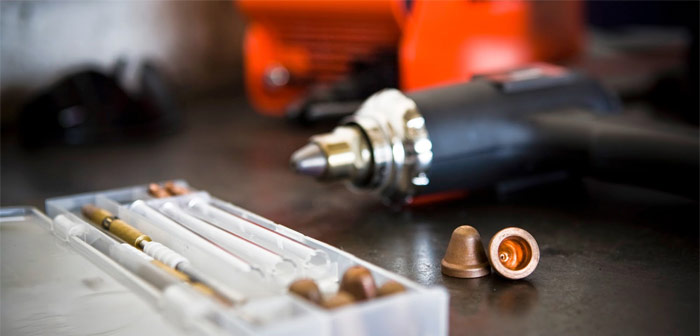
И вот тут возникает первая проблема. Ёмкость колбы с рабочей жидкостью для бытовых плазмоизлучателей (и, соответственно, время непрерывной работы аппарата) составляет:
- Для «Мультиплаз-2500»: часовой расход рабочей среды – 0,15…0,20 л/ч, при времени беспрерывной работы — в пределах 20…25 мин;
- Для «Мультиплаз-3500»: часовой расход рабочей среды – 0,25…0,30 л/ч, при времени беспрерывной работы — в пределах 10…15 мин;
- Для «Мультиплаз-4000»: часовой расход рабочей среды – 0,40…0,50 л/ч, при времени беспрерывной работы — в пределах 8…12 мин.
Не очень много, особенно, если разрезается или сваривается поверхность большого объёма или толщины. Поэтому работу приходится прекращать, и дозаправлять ёмкость. При этом свеженаложенный шов быстро остывает, и его конечные параметры при продолжении сварки могут существенно отличаться от первого участка. Напомним, что сварку агрегатами серии «Мультиплаз» целесообразно применять для соединений с повышенными показателями прочности и долговечности.

Вторая особенность работы с данной техникой – наличие опыта и овладения приёмами эксплуатации, которые нехарактерны для традиционной сварки. Зачастую именно этим объясняется большинство негативных отзывов о мультиплазах всех описываемых серий. Специфика работы заключается в следующем:
- Дуга поджигается методом осцилляции. Этот способ – довольно длительный, и уступает по простоте реализации традиционному контактному.
- Сразу после дозаправки работать горелкой невозможно, потому что её необходимо вывести на рабочий режим: прогреть в течение 3…4 минут. Нельзя работать также при кратковременных перерывах: паровая рубашка разрушается. Правда, в этом случае потребуется более кратковременный прогрев – не более 1,5…2 мин.
- Параметры столба плазмы зависят от расхода и качества жидкости, которая подаётся в зону обработки для последующего испарения. В частности, если водоспиртовая смесь заканчивается, то температура в столбе падает (судя по цвету факела – не менее чем на 1000 °С). Соответственно, снизится и качество шва.
- Особенности управления параметрами плазмы, в частности, порогового значения начального напряжения, которое не должно превышать 160…170 В. При этом изменение во времени напряжения поджига никак не отмечается в инструкции, и его следует устанавливать индивидуально.

Недостатки технологии и пути их преодоления
Большинство пользователей отмечают неудачную эргономику установки. Сам пистолет в плазмоизлучателе компактен и довольно лёгок (в частности, для модели «Мультиплаз-2500»), но не обеспечивает возможность проведения сварки или резки в труднодоступных местах.
Цена аппаратов довольно высока. Для «Мультиплаз-2500» она стартует с 30000 рублей, что существенно дороже, чем сварочные инверторы, газокислородные резаки и т.д. За «Мультиплаз-4000» придётся выложить уже 140 тыс. рублей.
Главное же – для эффективного применения мультиплазов в быту потребуется приобрести сноровку и опыт. Отечественные умельцы предлагают различные способы доработки рассматриваемой техники, которые можно реализовать в домашних условиях. К ним относятся:
- Оснащение аппаратов дополнительными ёмкостями с рабочей жидкостью, которые посредством гибких трубопроводов могли бы быстро подключаться к устройству. За счёт этого удаётся увеличить объём подаваемой рабочей среды вдвое, без утраты аппаратом своей компактности.
- Перенос кнопки включения на рукоятку пистолета, что создаёт удобства управления техникой.
- Изменения формы сопла с прямой на изогнутую (как вариант, таким соплом могли бы комплектовать аппарат его производители, но вместо этого они предлагают только два варианта горелки – под резку и сварку соответственно).
- Способы очистки катода и анода. Предполагается, что сама рабочая жидкость будет это делать, но её интенсивное испарение (особенно к концу заправки) способствует образованию нагара на поверхностях инструмента, что ухудшает энергические параметры плазмы и снижает стойкость электродов (практически она не превышает 40…50 часов). Поэтому некоторые изобретатели проделывают в нижней части горелок мультиплазов небольшие отверстия, куда шприцом закачивают рабочую жидкость. Считается, что в таком случае химический состав жидкой смеси будет более равномерным, и термические параметры столба плазмы станут стабильнее.

Суммируя всё изложенное выше, необходимо отметить:
- Мультиплазы вполне можно использовать в домашних условиях: они не отличаются высокими энергозатратами, удобны в хранении, экологически безопасны, не требуют дефицитных компонентов (газа, соответственно – баллонов, шлангов и пр.);
- Данными устройствами можно соединять и разрезать все материалы, которые трудно поддаются обычным методам сварки и резки;
- Бытовые исполнения техники не могут работать со сложными и объёмными заготовками, а также разрезать толстолистовой прокат, зато вполне приемлемы для точной контурной резки и сварки;
- Шов получается более качественным из-за отсутствия брызг. Также можно сэкономить на последующей очистке соединённых поверхностей, поскольку видимых дефектов практически не наблюдается.
Главное же заключается в том, что агрегаты серии «Мультиплаз» не являются универсальными, а потому имеют свою оптимальную нишу использования.