перейти к содержанию
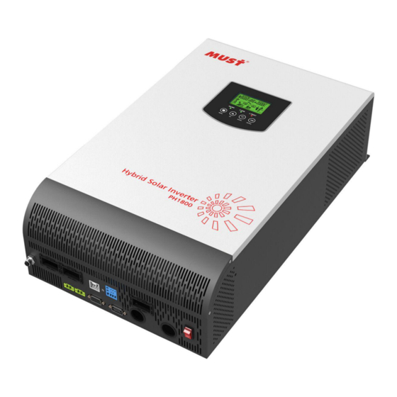
![]() Высокочастотный автономный солнечный инвертор серии PV1800 VHM
Высокочастотный автономный солнечный инвертор серии PV1800 VHM
Руководство пользователя
 Особенности

- Номинальная мощность: 2кВт-5.5кВт
- Чистый синусоидальный солнечный инвертор
- Коэффициент выходной мощности 1
- Встроенное солнечное зарядное устройство MPPT на 80 А.
- Встроенный комплект для защиты от пыли для суровых условий
- Поддержка параллельной работы до 3 устройств (доступно для 3 кВт-5.5 кВт 48 В)
- Удаленный мониторинг WIFI (опционально)
- Совместимость с генератором
Введение
PV1800 VHM — это многофункциональный инвертор/зарядное устройство, сочетающий в себе функции инвертора, солнечного зарядного устройства и зарядного устройства для аккумуляторов, обеспечивающий бесперебойную работу в портативном размере. Его всеобъемлющий ЖК-дисплей предлагает настраиваемую пользователем и легкодоступную кнопочную операцию, такую как ток зарядки аккумулятора, приоритет зарядного устройства переменного тока / солнечной батареи и приемлемую входную громкость.tage на основе различных приложений.
Описание печати на задней панели
- ЖК дисплей
- Индикатор состояния
- Индикатор зарядки
- Индикатор неисправности
- Кнопки функций

- вход переменного тока
- Выход переменного тока
- Выключатель
- Вход батареи
- PV вход
- Выключатель питания вкл / выкл
- Порт связи RS-485
- USB
- Сухой контакт
- usb-wi-fi
- Параллельный переключатель
- Параллельный коммуникационный порт (только для параллельной модели)

Подключение солнечной системы

Спецификация
| МОДЕЛЬ | ПВ18-2024 ОБМ |
ПВ18-3024 ОБМ |
ПВ18-3048 ОБМ |
ПВ18-4048 ОБМ |
ПВ18-5048 ОБМ |
ПВ18-5548 ОБМ |
|
| Номинальный объем аккумуляторной системыtage | 2IVDC | ||||||
| Инвертор ВЫВОД |
Номинальная мощность | 2000W | 3000W | 3000W | 4000W | 5000W | 5500W |
| Всплеск мощности | 4000W | 6000W | 6000W | 8000W | 10000W | 11000W | |
| Waveform | Чистая синусоида | ||||||
| том переменного токаtage Регулирование (BattMode) | (220В~-240В~)±5% | ||||||
| Эффективность инвертора (пиковая) | 93% | ||||||
| Время передачи | тома (ИБП и VDE4105) 20 мс (APL) | ||||||
| AC INPUT | Voltage | 230VAC | |||||
| Выбираемый объемtage Диапазон | 170-280VAC(UPS)/ 90-280VAC(APL) i 184-253VAC(VDE4105) | ||||||
| Диапазон частот | 50 Гц / 60 Гц (автоматическое определение) | ||||||
| БАТАРЕИ | Нормальная громкостьtage | 2IVDC | 48 DC | ||||
| Плавающий объем зарядаtage | 27.IVDC | 51.8 DC | |||||
| Защита от перезарядки | 30 DC | 60 DC | |||||
| СОЛНЕЧНОЕ ЗАРЯДНОЕ УСТРОЙСТВО И ЗАРЯДНОЕ УСТРОЙСТВО ПЕРЕМЕННОГО ТОКА | Максимальный PV Amy Open Circuit vdtage | 145 DC | |||||
| PV массив MPPT Voltage Диапазон | 30-130VDC | 60-130VDC | |||||
| Энергопотребление в режиме ожидания | 2W | ||||||
| Входная мощность фотоэлектрических модулей | 2000W | 4000W | |||||
| Максимальный ток солнечного заряда | 80A | ||||||
| Максимальная эффективность | 98% | ||||||
| Максимальный ток зарядки переменного тока | 201 / 33A | 60A | |||||
| Максимальный ток зарядки | 80A | 140A | |||||
| МЕХАНИЧЕСКИЕ ХАРАКТЕРИСТИКИ |
Размеры машины (N•H•DXмм) | 300’4141’116 | 329’485’134 | ||||
| Размер упаковки (WH’D) (ммл | 123’599’257 | 426.5’507’250 | |||||
| Вес неттоgre) | 10 | 11 | 12 | ||||
| Вес брутто (кг) | 12 | 12 | 14 | ||||
| ДРУГИЕ | Влажность | 5% 095% Ftelaby Hurnidtty (без конденсации) | |||||
| Рабочая Температура | 0°C-50•C | ||||||
| Температура хранения | -15°С -60°С |
Технические характеристики этого документа могут быть изменены без предварительного уведомления.![]()
Документы / Ресурсы
-
Contents
-
Table of Contents
-
Troubleshooting
-
Bookmarks
Quick Links
Service Manual
PV18-2K/3K HM
Inverter/Charger
PV1800 2K/3K HM
Service Manual
Related Manuals for Must PV1800 2K HM
Summary of Contents for Must PV1800 2K HM
-
Page 1
Service Manual PV18-2K/3K HM Inverter/Charger PV1800 2K/3K HM Service Manual… -
Page 2: Table Of Contents
Service Manual PV18-2K/3K HM Table of Contents 1. General Information………………..1 1.1 Brief Introduction ………………..1 1.2 Basic Topology Introduction………………1 1.3 Overview of Inverter/Charger………………2 2. Fault and Troubleshooting………………3 3. Steps to Repair ………………….4 3.1 Maintenance………………….4 3.1.1 To Check DC FUSE and Capacitance…………4 3.1.2 DC/DC Boost Module………………5 3.1.3 Divers………………….6 3.2 To Check BUS Module………………..9…
-
Page 3: General Information
Service Manual PV18-2K/3K HM 1. General Information 1.1 Brief Introduction This manual is used as a tool of inspection and repairing guidance for PV18-2K/3K HM, as well as instructions of assembling and testing. It is best to have some electrical or electronic background knowledge. With this guidance, hope it will help you to check and inspect the inverter/charger first by yourself.
-
Page 4: Overview Of Inverter/Charger
Service Manual PV18-2K/3K HM 1.3 Over review and Introduction of Inverter /charger Parts Main Board Solar Charge Controller & Control Board — 2 -…
-
Page 5: Fault And Troubleshooting
Service Manual PV18-2K/3K HM 2. Fault and Troubleshooting No LCD First to test battery volt to check whether it is in range of 44v-52v; display when If it is in the range, to switch the inverter one to check whether the inverter turns unit starts.
-
Page 6: Steps To Repair
Service Manual PV18-2K/3K HM 3. Steps to Repair 3.1 Battery Working Mode Test 3.1.1 To Check DC FUSE and Capacitance F1-F6: 180-00001-00 (Fuse, F40A/32VDC UL) Positioning Attribute Reference Value Failure Status F1-F6 Resistor 0 ohm open C19,C20,C39,C40: 140-00093-00 (Electrolytic Capacitor, 4200uF 35V M RAD 7.5mm 105℃) — 4 -…
-
Page 7: Dc/Dc Boost Module
Service Manual PV18-2K/3K HM If the capacitors explode, they need to be replaced. 3.1.2 DC/DC Boost Module 150-00052-00:MOSFET TI/CSD19505KCS 201A 80V N BULK TO-220 Positioning Attribute Reference Value Failure Status All MOSFET, 8pcs Diode SD:0.44V Short-circuit DS:OL or Explosion Note If one or more than one of them were broken, please replace all of them. For 2K, the main board has just 6pcs MOSFETS.
-
Page 8: Divers
Service Manual PV18-2K/3K HM 3.1.3 Divers Note: when there are power devices or components are damaged, Divers are usually required to check. The reference resistors listed as below. R373,R7,R8,R9,R10,R11,R12,R13,R14,R79,R257 All the resistors are 100-10010-00 (RES CHIP TF 1/4W 10 F(1206)) To use Multi-meter to measure each resistors till to find out the broken ones and to replace them, no need to change all the resistors.
-
Page 9
Service Manual PV18-2K/3K HM UC2,UC4:150-00005-00 (Plug-in Transistor TOSHIBA/2SC2655-Y 2A 50V) UC1,UC3:150-00004-00 (Plug-in Transistor TOSHIBA/2SA1020-Y 2A 50V) — 7 -… -
Page 10
Service Manual PV18-2K/3K HM Positioning Attribute Reference Value Failure Status UC2,UC4 Diode BE:0.6V Short-circuit or burnt BC:0.6V CE:1V UC1,UC3 Diode BE:0.6V Short-circuit or burnt BC:1.3V CE:0.2V Pin9 Pin16 Pin9 Pin16 Pin1 Pin1 Pin8 Pin8 U3: 160-00006-00 ( Plug-In : IC LINEAR FAIRCHILD/KA3525A) Positioning Attribute Reference Value… -
Page 11: To Check Bus Module
Service Manual PV18-2K/3K HM 3.2 To Check BUS Module 3.2.1 Rectifier Diode D17,D18,D19,D20 Rectifier Diode: D17,D18,D19,D20: 150-10042-00 (FAIR./RHRP1560_NL 15A 600V) Positioning Attribute Reference Value Failure Status +to-: 0.37V D17,D18,D19,D20 Diode Short Circuit -to+: OL or Broken Note: If there is one or more than one components broken, please replace them all. — 9 -…
-
Page 12: To Check Full Bridge Invert Circuit
Service Manual PV18-2K/3K HM 3.3 To Check Full-Bridge Invert Circuit 3.3.1 Power Parts Q16,Q17,Q18,Q19:150-30088-00 (IGBT IR/IRGP4063D-EPBF 48A 600V TO-247) Positioning Attribute Reference Value Failure Status Q16,Q17,Q18,Q19 Diode EC: 0.4V Short Circuit CE: OL or Broken 3.3.2 Divers INV IGBT: Q16,Q17,Q18,Q19 — 10 -…
-
Page 13
Service Manual PV18-2K/3K HM R53,R55,R60,R63: 100-17047-00 (SMD Resistor CHIP TF 1/4W 4.7 F(1206)) R54,R56,R61,R64: 100-10100-00 (SMD Resistor CHIP TF 1/4W 100 F(1206)) ZD2,ZD3: 120-20072-00 (SMD Zen-er Diode PAN JIT 1SMA4745 16V 1W SMD) D10,D12: 120-20007-00 (SMD Diode PANJIT/SS14 1A 40V SMD) Positioning Attribute Reference Value… -
Page 14: To Check Drivers
Service Manual PV18-2K/3K HM 3.3.3 To Check Drivers U24,U25,U26,U27: 120-10065-00 (IC Driver Chip FOD3120 SMT) Positioning Attribute Reference Value Failure Status U24,U25,U26,U27 Resistor Pin8-Pin5: 2K Short Circuit Pin7-Pin5:2K or Broken C150/C151: 110-10040-00 ( SMD Capacitors CER MT 10nF 50V J NPO 103 (0805)) Positioning Attribute Reference Value…
-
Page 15: To Check Ac Charging Circuit
Service Manual PV18-2K/3K HM 3.4 To Check AC Charging Circuit 3.4.1 To Check Power Components Q20,Q21,Q22: 150-30032-00 ( Plug-in Transistor TSB/2SK3878 9A 900V N TUBE TO-3PN) Positioning Attribute Reference Value Failure Status Q20,Q21,Q22 Diode EC: 0.4V Short Circuit CE: OL or Broken Note: If there is one or more than one components broken, please replace them all.
-
Page 16
Service Manual PV18-2K/3K HM Positioning Attribute Reference Value Failure Status R259,R261,R263 Resistor 10 ohm Open Circuit other value R258,R260,R262 Resistor 100 ohm D56/D57/D58 Diode EC: 0.6V Short Circuit CE: OL or Broken Note: When test diodes, please remove R259, R261, R263, otherwise the test result is not right. -
Page 17: To Check Rectifier Circuit
Service Manual PV18-2K/3K HM 3.5 To Check Rectifier Circuit 3.5.1 Charging Circuit D21/D22/D23: 150-10061-00 (Plug-in Diode ON/MBR20200CT 20A 200V SCKY RAD BULK) REC1: 150-10066-00 ( Plug-in Diode HY/GBU8M 8A1000V ) ~ ~ — 15 -…
-
Page 18: To Check Power Circuit
Service Manual PV18-2K/3K HM Positioning Attribute Reference Value Failure Status D21/D22/D23 Diode P to N: 0.44V ; N to P: OL Short Circuit REC1 Diode ~ to +: 0.47V ; + to ~: OL or Broken — to ~: 0.47; ~ to -: OL 3.6 To Check Power Circuit Q1: 150-30005-00 ( Plug-in Transistor MOSFET IR/IRF640NPBF18A 200V) R1: 130-00211-00 ( Plug-in Resistor 3WS 0.15 J Rack F4)
-
Page 19
Service Manual PV18-2K/3K HM CE6: 140-00044-00 (Electrolytic Capacitor 470uF35V M 5mm 105℃ 10*16mm Tape) If the capacitor appears burst, please replace it. R31: 100-17022-00 ( SMD Resistor CHIP TF 1/4W 2.2 F (1206) ) D1: 150-10009-00 (Plug-in Diode PAJIT/UF204 2A 400V ULTRAFAST AXI) ZD4: 120-20072-00 ( SMD Zen-er Diode PAN JIT 1SMA4745 16V 1W SMD ) U11: 120-10037-00 (IC ON/MC78M05CDTG DPAK-3 SMD) ZD12… -
Page 20
Service Manual PV18-2K/3K HM R99: 100-30022-00 ( SMD Resistor CHIP TF 1W 2.2 F (0207) ) D34: 120-20048-00 (SMD Diode ON/MURA120T3 1A 200V 403D SMD) Positioning Attribute Reference Value Failure Status Diode SD: 0.5V ; DS: OL Short Circuit Diode + to -: 0.47V ;… -
Page 21: To Check Mosfets For Reversed Protection On Dc Terminal
Service Manual PV18-2K/3K HM 3.7 To Check MOSFETS for Reversed Protection on DC Terminal Please open the cover and measure as follows. PV — BAT — Positioning Attribute Reference Value Failure Status PV — to BAT — Resistor >10K Short Circuit If in Short Circuit, Please replace MOSFET in Main Board.
-
Page 22: To Check Ntc Circuit
Service Manual PV18-2K/3K HM 3.8 To Check NTC Circuit On Main Board, there are three NTC, one is in DC-DC Boost Heat Sink, one is under boost transformer and one is in inverting heat sink. When 02 fault code appears, it requires to check this step, please kindly note. 3.8.1 NTC in position of HS3 plugs in position of SW1 on main board.
-
Page 23: Ntc In Hs4
Service Manual PV18-2K/3K HM Positioning Attribute Reference Value Failure Status NTC4 Resistor 5.7K ohm Short Circuit or Open Circuit 3.8.3 NTC in HS4 NTC_HS4: 130-20005-00 (Thermistor NTC 15K 2.5mA KW) NTC4 NTC4 — 21 -…
-
Page 24: To Check Fan Driver Circuit
Service Manual PV18-2K/3K HM Positioning Attribute Reference Value Failure Status NTC_HS4 Resistor 5.5K ohm Short Circuit or other value If it is not possible to check functioning, please make NTC short-circuit and test the inverter again; if the fault disappears, it means the NTC is wrong. 3.9 To Check Fan Drive Circuit CN10 — 22 -…
-
Page 25: Other Common Faulty Cases
Service Manual PV18-2K/3K HM Positioning Attribute Reference Value Failure Status R319/R329 100K ohm Short Circuit R321/R325/R326/R331 Resistor 10K ohm Other Value R320/R330 100 ohm D62/D65 Diode + to -:0.6V ; — to +: OL Short Circuit Burst Q34/Q35 SD: 0.5V ; DS: OL 4.
-
Page 26: Dust-Covered Control Board
Service Manual PV18-2K/3K HM 4.3 Dust-covered Control Board 5. Assembling Guidance 5.1 Unfix Upper Cover 5.1.1 Unscrew four screws of the cover as following 5.1.2 Pluck LCD disconnection cable and take the cover — 24 -…
-
Page 27
Service Manual PV18-2K/3K HM 5.2 Unfix Power Board 5.2.1 To take the Air-duct Paper To take five plastic nails in heat sink and take out the air-duct paper 5.2.2 To pluck AC input and output cable and fan connection cable — 25 -… -
Page 28: Test Guidance After Repairing
Service Manual PV18-2K/3K HM 5.2.3 To Remove PV Connection Cable 5.2.4 To Remove the two screws on the side and take out the middle clapboard 5.2.5 Unscrew the two screws in control board and take the control board out. — 26 -…
-
Page 29
Service Manual PV18-2K/3K HM 5.2.6 Unscrew the eleven screws in main boards and take main board out. 5.3 Assembling the Inverter When Assemble the unit, please take opposite order of dissembling. 6. Test after Repairing 6.1 Before test, please connect to battery bank. — 27 -… -
Page 30
Service Manual PV18-2K/3K HM Afterwards, please Turn ON the unit. 6.2 To connect with AC Grid for testing — 28 -… -
Page 31
Service Manual PV18-2K/3K HM 6.3 To connect PV for testing — 29 -…
-
Contents
-
Table of Contents
-
Troubleshooting
-
Bookmarks
Quick Links
Related Manuals for Must Power PV18 Series

Summary of Contents for Must Power PV18 Series
-
Page 1
2KW-3KW… -
Page 3: Table Of Contents
Table Of Contents ABOUT THIS MANUAL ………………Purpose ………………….Scope ………………….SAFETY INSTRUCTIONS………………INTRODUCTION………………..Features ………………….Basic System Architecture ……………… Product Overview ………………… INSTALLATION………………..Unpacking and Inspection …………….. Preparation ………………..Mounting the Unit ……………….. Battery Connection ………………. AC Input/Output Connection …………….
-
Page 4: About This Manual
ABOUT THIS MANUAL Purpose This manual describes the assembly, installation, operation and troubleshooting of this unit. Please read this manual carefully before installations and operations. Keep this manual for future reference. Scope This manual provides safety and installation guidelines as well as information on tools and wiring. The following cases are not within the scope of warranty: (1) Out of warranty.
-
Page 5: Introduction
INTRODUCTION This is a multi-function inverter/charger, combining functions of inverter, solar charger and battery charger to offer uninterruptible power support with portable size. Its comprehensive LCD display offers user-congurable and easy-accessible button operation such as battery charging current, AC/solar charger priority, and acceptable input voltage based on different applications. Features Pure sine wave inverter Congurable input voltage range for home appliances and personal computers via LCD setting…
-
Page 6: Product Overview
Product Overview 1. LCD display 2. Status indicator 3. Charging indicator 4. Fault indicator 5. Function buttons 6. Power on/off switch 7. AC input 8. AC output 9. PV input 10. Battery input 11. Circuit breaker 12. RS-485 communication port 13.
-
Page 7: Installation
INSTALLATION Unpacking and Inspection Before installation, please inspect the unit. Be sure that nothing inside the package is damaged. You should have received the following items inside of package: The unit x 1 User manual x 1 Communication cable x 1 USB cable x 1 Software CD X 1 Preparation…
-
Page 8: Battery Connection
Install the unit by screwing three screws. 2~3KW Battery Connection CAUTION: To safety operation and regulation compliance, it’s requested to install a separate DC over-current protector or disconnect device between battery and inverter. It may not be requested to have a disconnect device in some applications, however, it’s still requested to have over-current protection installed.
-
Page 9: Ac Input/Output Connection
3. Insert the ring terminal of battery cable atly into battery connector of inverter and make sure the bolts are tightened with torque of 2-3 Nm. Make sure polarity at both the battery and the inverter/charge is correctly connected and ring terminals are tightly screwed to the battery terminals.
-
Page 10: Pv Connection
→Ground (yellow-green) L→LINE (brown or black) N→Neutral (blue) WARNING: Be sure to that AC power source is disconnected before attempting to hardwire it to the unit. 4. Then, insert AC output wires according to polarities indicated on terminal block and tighten terminal screws.
-
Page 11
Torque Value Typical Amperage Typical Amperage Cable Size 8AWG 1.4~1.6Nm 2KW~3KW 6AWG 2.0~2.4Nm PV Module Selection: When selecting proper PV modules, please be sure to consider below requirements rst: 1. Open circuit Voltage (Voc) of PV modules not exceeds max. PV array open circuit voltage of inverter. 2. -
Page 12: Final Assembly
Solar panel installation schematic MPPT-60A MPPT-80A Final Assembly After connecting all wirings, please put bottom cover back by screwing two screws as shown below.
-
Page 13: Communication Connection
Communication Connection Please use supplied communication cable to connect to inverter and PC. Insert bundled CD into a computer and follow on-screen instruction to install the monitoring software. For the detailed software operation, please check user manual of software inside of CD. WARNING: It’s forbidden to use network cable as the communication cable to directly communicate with the PC port.
-
Page 14: Operation
OPERATION Power ON/OFF Once the unit has been properly installed and the batteries are connected well, simply press On/Off switch (located on the button of the case) to turn on the unit. Operation and Display Panel The operation and display panel, shown in below chart, is on the front panel of the inverter. It includes three indicators, four function keys and a LCD display, indicating the operating status and input/output power information.
-
Page 15: Lcd Display Icons
LCD Display Icons Icon Function description Input Source Information and Output Information Indicates the AC information. Indicates the DC information. Indicate input voltage, input frequency, PV voltage, battery voltage and charger current. Indicate output voltage, output frequency, load in VA, load in Watt and discharging current.
-
Page 16
In battery mode, it will present battery capacity. Load Percentage Battery Voltage LCD Display < 1.717V/cell 1.717V/cell ~ 1.8V/cell Load >50% 1.8 ~ 1.883V/cell > 1.883 V/cell < 1.817V/cell 1.817V/cell ~ 1.9V/cell 50%> Load > 20% 1.9 ~ 1.983V/cell > 1.983V/cell <… -
Page 17: Lcd Setting
LCD Setting After pressing and holding «ENTER» button for 2 seconds, the unit will enter setting mode, and then, press «ENTER» or «MENU» button to conrm the selection and exit. Press «UP» or «DOWN» button to select setting programs. Setting Programs: Program Description Selectable option…
-
Page 18
If selected, acceptable AC input Appliances (default) voltage range will be within 90- 280VAC. If selected, acceptable AC input voltage range will be within AC input voltage range 170-280VAC. If selected, acceptable AC input voltage range will conform to VDE4105(184VAC-253VAC) When the user uses the device to connect the generator, select the generator mode. -
Page 19
Solar and Utility Solar energy and utility will (default) charge battery at the same time. Only Solar Solar energy will be the only charger source no matter utility is available or not. If this inverter/charger is working in Battery mode or Power saving mode, only solar energy can charge battery. -
Page 20
Low DC cut off battery voltage setting If «User-Dened» LI is selected in program 14, this program can be set up. Setting range is from 20.0V to 24.0V for 24Vdc model. Increment of each click is 0.1V. Low DC cut-off voltage will be xed to setting value no matter what percentage of load is connected. -
Page 21: Fault Reference Code
Fault Reference Code Fault Code Fault Event Icon on Fan is locked when inverter is off Inverter transformer over temperature battery voltage is too high battery voltage is too low Output short circuited Inverter output voltage is high Overload time out Inverter bus voltage is too high Bus soft start failed Main relay failed…
-
Page 22: Warning Indicator
Inverter grid under frequency Inverter grid over frequency Inverter over current protection error Inverter bus voltage is too low Inverter soft start failed Over DC voltage in AC output Battery connection is open Inverter control current sensor error Inverter output voltage is too low Warning Indicator Icon on Fault Code…
-
Page 23: Operating Mode Description
Operating State Description Operation state Description LCD display PV is on PV energy is charger Utility-Tie state into the battery and utility provide power to the AC load. PV is off Charge state PV energy and grid can charge batteries. Bypass state Error are caused by inside circuit error or…
-
Page 24: Display Setting
Display Setting The LCD display information will be switched in turns by pressing «UP» or «DOWN» key. The selectable information is switched as below order: battery voltage, battery current ,inverter voltage, inverter current, grid voltage, grid current, load in Watt, load in VA, grid frequency, inverter frequency, PV voltage, PV charging power, PV charging output voltage, PV charging current.
-
Page 25: Specifications
SPECIFICATIONS Table 1 Line Mode Specications INVERTER MODEL Input Voltage Waveform Sinusoidal (utility or generator) Nominal Input Voltage 230Vac 90Vac±7V(APL,GEN); 170Vac±7V(UPS) Low Loss Voltage 186Vac±7V(VDE) 100Vac±7V(APL,GEN);180Vac±7V(UPS) Low Loss Return Voltage 196Vac±7V(VDE) 280Vac±7V(APL, UPS,GEN) High Loss Voltage 253Vac±7V(VDE) 270Vac±7V(APL,UPS,GEN) High Loss Return Voltage 250Vac±7V(VDE) Max AC Input Voltage 300Vac…
-
Page 26: Table 2 Inverter Mode SpeciCations
Table 2 Inverter Mode Specications INVERTER MODEL Rated Output Power 2KW/2000W 3KW/3000W Output Voltage Waveform Pure Sine Wave Output Voltage Regulation 230Vac±5% Output Frequency 60Hz or 50Hz Peak Efciency 5s@≥150% load; 10s@110%~150% load Overload Protection Nominal DC Input Voltage 24Vdc Cold Start Voltage 23.0Vdc Low DC Warning Voltage…
-
Page 27: Table 3 Charge Mode SpeciCations
Table 3 Charge Mode Specications Utility Charging Mode INVERTER MODEL Charging Current 20/30A @Nominal Input Voltage AGM / Gel/LEAD 25Vdc Absorption Battery Voltage Flooded Battery 25Vdc AGM / Gel/LEAD 27.4Vdc Reoat Battery Voltage Flooded Battery 27.4Vdc AGM / Gel/LEAD 28.8Vdc Float Battery Voltage…
-
Page 28: Table 4 General SpeciCations
Charging algorithm for Lithium battery Joint Utility and Solar Charging 2KW/3KW INVERTER MODEL MPPT-60A MPPT-80A CHARGER MODEL Max Charging Current Default Charging Current Table 4 General Specications INVERTER MODEL Safety Certication Operating Temperature Range 0°C to 50°C Storage temperature -15°C~ 60°C Dimension (D*W*H), mm 290 x 396 x 108 Net Weight, kg…
-
Page 29: Trouble Shooting
TROUBLE SHOOTING Explanation/Possible cause What to do LCD/LED/Buzzer Problem Unit shuts down LCD/LEDs and buzzer automatically will be active for 3 The battery voltage is too low. 1. Re-charge battery. during startup seconds and then (<1.91V/Cell) 2. Replace battery. process. complete off.
-
Page 30: Appendix: Approximate Back-Up Time Table
Appendix: Approximate Back-up Time Table Load (W) Backup Time @ 24Vdc 100Ah (min) Backup Time @ 24Vdc 200Ah (min) Model 1610 1000 1200 1400 1600 1800 2000 1100 1200 1500 1800 2100 2400 2700 3000 Note: Backup time depends on the quality of the battery, age of battery and type of battery. Specications of batteries may vary depending on different manufacturers.
-
Page 32
SOLAR INVERTER/CHARGER 420-00343-00…