- Manuals
- Brands
- ASROCK Manuals
- Motherboard
- N68C-GS UCC —
- User manual
-
Contents
-
Table of Contents
-
Bookmarks
Quick Links
N68C-GS UCC /
N68C-S UCC
User Manual
Version 1.1
Published March 2010
Copyright©2010 ASRock INC. All rights reserved.
1 1 1 1 1
Related Manuals for ASROCK N68C-GS UCC
Summary of Contents for ASROCK N68C-GS UCC
-
Page 1
N68C-GS UCC / N68C-S UCC User Manual Version 1.1 Published March 2010 Copyright©2010 ASRock INC. All rights reserved. 1 1 1 1 1… -
Page 2
(including damages for loss of profits, loss of business, loss of data, interruption of business and the like), even if ASRock has been advised of the possibility of such damages arising from any defect or error in the manual or product. -
Page 3: Table Of Contents
Serial ATA (SATA) / Serial ATAII (SATAII) Hard Disks Installation …………….. 26 2.10 Hot Plug and Hot Swap Functions for SATA / SATAII HDDs ..26 2.11 SATA / SATAII HDD Hot Plug Feature and Operation Guide ..27 2.12 Driver Installation Guide …………29 2.13 Installing Windows…
-
Page 4
Hardware Health Event Monitoring Screen ……53 Boot Screen …………….54 3.6.1 Boot Settings Configuration ……….. 54 Security Screen ……………. 55 Exit Screen …………….56 4 . 4 . 4 . 4 . 4 . Software Support Software Support Software Support Software Support …………………. -
Page 5: Introduction Introduction
It delivers excellent performance with robust design conforming to ASRock’s com- mitment to quality and endurance. In this manual, chapter 1 and 2 contain introduction of the motherboard and step-by-step guide to the hardware installation. Chapter 3 and 4 contain the configuration guide to BIOS setup and information of the Support CD.
-
Page 6: Specifications
— Micro ATX Form Factor: 9.6-in x 8.2-in, 24.4 cm x 20.8 cm Platform — Support for Socket AM2+ / AM2 processors: AMD Phenom FX / Phenom / Athlon 64 FX / Athlon 64 X2 Dual-Core / Athlon X2 Dual-Core / Athlon 64 / Sempron processor (see CAUTION 1)
-
Page 7
— 1 x VGA Port — 4 x Ready-to-Use USB 2.0 Ports — 1 x RJ-45 LAN Port with LED (ACT/LINK LED and SPEED LED) — HD Audio Jack: Line in / Front Speaker / Microphone — 4 x Serial ATAII 3.0Gb/s connectors, support RAID (RAID 0, Connector RAID 1, RAID 0+1, RAID 5, JBOD), NCQ and “Hot Plug”… -
Page 8
Overclocking may affect your system stability, or even cause damage to the components and devices of your system. It should be done at your own risk and expense. We are not responsible for possible damage caused by overclocking. -
Page 9
Please be noted that the USB flash drive or hard drive must use FAT32/ 16/12 file system. 14. The software name itself – OC DNA literally tells you what it is capable of. OC DNA, an exclusive utility developed by ASRock, provides a conve- nient way for the user to record the OC settings and share with others. -
Page 10
17. This motherboard supports ASRock AM2 Boost overclocking technology. If you enable this function in the BIOS setup, the memory performance will improve up to 12.5%, but the effect still depends on the AM2 CPU you adopt. Enabling this function will overclock the chipset/CPU reference clock. However, we can not guarantee the system stability for all CPU/DRAM configurations. -
Page 11: Motherboard Layout (N68C-Gs Ucc / N68C-S Ucc)
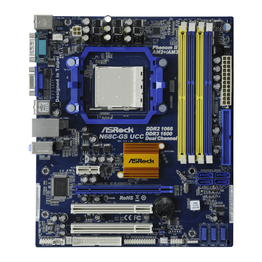
1.3 Motherboard Layout (N68C-GS UCC / N68C-S UCC) 1.3 Motherboard Layout (N68C-GS UCC / N68C-S UCC) 1.3 Motherboard Layout (N68C-GS UCC / N68C-S UCC) 1.3 Motherboard Layout (N68C-GS UCC / N68C-S UCC) 1.3 Motherboard Layout (N68C-GS UCC / N68C-S UCC) 20.8cm (8.2-in)
-
Page 12: I/O Panel (N68C-Gs Ucc)
VGA Port Front Speaker (Lime) COM Port Microphone (Pink) PS/2 Keyboard Port (Purple) * There are two LED next to the LAN port. Please refer to the table below for the LAN port LED indications. LAN Port LED Indications ACT/LINK SPEED…
-
Page 13: I/O Panel (N68C-S Ucc)
VGA Port Front Speaker (Lime) COM Port Microphone (Pink) PS/2 Keyboard Port (Purple) * There are two LED next to the LAN port. Please refer to the table below for the LAN port LED indications. LAN Port LED Indications ACT/LINK SPEED…
-
Page 14: Installation
Installation Installation Installation This is a Micro ATX form factor (9.6-in x 8.2-in, 24.4 cm x 20.8 cm) motherboard. Before you install the motherboard, study the configuration of your chassis to en- sure that the motherboard fits into it. Pre-installation Precautions…
-
Page 15: Cpu Installation
Step 4. When the CPU is in place, press it firmly on the socket while you push down the socket lever to secure the CPU. The lever clicks on the side tab to indicate that it is locked.
-
Page 16: Installation Of Memory Modules (Dimm)
Channel Memory Technology. For dual channel configuration, you always need to install identical (the same brand, speed, size and chip-type) DDR2/DDR3 DIMM pair in the slots of the same color. In other words, you have to install identical DDR2 DIMM pair in Dual Channel (DDRII_1 and DDRII_2; Yellow slots;…
-
Page 17
DIMMs or the system components. Step 1. Unlock a DIMM slot by pressing the retaining clips outward. Step 2. Align a DIMM on the slot such that the notch on the DIMM matches the break on the slot. notch break… -
Page 18: Expansion Slots (Pci And Pci Express Slots)
PCI slots: PCI slots are used to install expansion cards that have the 32-bit PCI interface. PCIE slots: PCIE1 (PCIE x1 slot) is used for PCI Express cards with x1 lane width cards, such as Gigabit LAN card, SATA2 card, etc.
-
Page 19: Easy Multi Monitor Feature
® to page 18 for proper expansion card installation procedures for details. 2. Connect the D-Sub monitor cable to the VGA/D-Sub port on the I/O panel of this motherboard. Connect another D-Sub monitor cable to the VGA/D-Sub connector of the add-on PCI Express VGA card. Connect the DVI-D monitor cable to the VGA/DVI-D connector of the add-on PCI Express VGA card.
-
Page 20: Jumpers Setup
CLRCMOS1 for 5 seconds. However, please do not clear the CMOS right after you update the BIOS. If you need to clear the CMOS when you just finish updating the BIOS, you must boot up the system first, and then shut it down…
-
Page 21: Onboard Headers And Connectors
(33-pin FLOPPY1) FLOPPY1 Pin1 (see p.11 No. 23) the red-striped side to Pin1 Note: Make sure the red-striped side of the cable is plugged into Pin1 side of the connector. Primary IDE connector (Blue) (39-pin IDE1, see p.11 No. 9) IDE1…
-
Page 22: Front Panel Audio Header
HDA to function correctly. Please follow the instruction in our manual and chassis manual to install your system. 2. If you use AC’97 audio panel, please install it to the front panel audio header as below: A.
-
Page 23: Chassis/Power Fan Connectors
Though this motherboard provides 4-Pin CPU fan (Quiet Fan) support, the 3-Pin CPU fan still can work successfully even without the fan speed control function. If you plan to connect the 3-Pin CPU fan to the CPU fan connector on this motherboard, please connect it to Pin 1-3.
-
Page 24
Though this motherboard provides 24-pin ATX power connector, it can still work if you adopt a traditional 20-pin ATX power supply. To use the 20-pin ATX power supply, please plug your power supply along with Pin 1 and Pin 13. -
Page 25: Sataii Hard Disk Setup Guide
Before installing SATAII hard disk to your computer, please carefully read below SATAII hard disk setup guide. Some default setting of SATAII hard disks may not be at SATAII mode, which operate with the best performance. In order to enable SATAII function, please follow the below instruction with different vendors to correctly adjust your SATAII hard disk to SATAII mode in advance;…
-
Page 26: Serial Ata (Sata) / Serial Ataii (Sataii) Hard Disks
STEP 2: Connect the SATA power cable to the SATA / SATAII hard disk. STEP 3: Connect one end of the SATA data cable to the motherboard’s SATAII connector. STEP 4: Connect the other end of the SATA data cable to the SATA / SATAII hard disk. 2 . 1 0 2 .
-
Page 27: Sata / Sataii Hdd Hot Plug Feature And Operation Guide
SATA / SATAII driver is available on our support website: www.asrock.com 4. Make sure to use the SATA power cable & data cable, which are from our motherboard package. 5. Please follow below instructions step by step to reduce the risk of HDD crash…
-
Page 28
Please do follow below instruction sequence to process the Hot Unplug, improper procedure will cause the SATA / SATAII HDD damage and data loss. Step 1 Unplug SATA data cable from SATA / SATAII HDD side. Unplug SATA 15-pin power cable connector (Black) from SATA / SATAII HDD side. Step 2… -
Page 29: Driver Installation Guide
2 . 1 2 Driver Installation Guide To install the drivers to your system, please insert the support CD to your optical drive first. Then, the drivers compatible to your system can be auto-detected and listed on the support CD driver page. Please follow the order from up to bottom side to install those required drivers.
-
Page 30: Installing Windows ® 7 / 7 64-Bit / Vista
(create, convert, delete, or rebuild) RAID functions on SATA / SATAII HDDs, you still need to set up “SATA Operation Mode” to [RAID] in BIOS first. Then, please set the RAID configuration by using the Windows RAID installation guide in the following path in the Support CD: ..
-
Page 31: Untied Overclocking Technology
(create, convert, delete, or rebuild) RAID functions on SATA / SATAII HDDs, you still need to set up “SATA Operation Mode” to [RAID] in BIOS first. Then, please set the RAID configuration by using the Windows RAID installation guide in the following path in the Support CD: ..
-
Page 32: Etup Utility
<Del> during the Power-On-Self-Test (POST) to enter the BIOS SETUP UTILITY, otherwise, POST will continue with its test routines. If you wish to enter the BIOS SETUP UTILITY after POST, restart the system by pressing <Ctl> + <Alt> + <Delete>, or by pressing the reset button on the system chassis.
-
Page 33: Navigation Keys
To jump to the Exit Screen or exit the current screen <ESC> Main Screen Main Screen Main Screen Main Screen Main Screen When you enter the BIOS SETUP UTILITY, the Main screen will appear and display the system overview. N68C-GS UCC BIOS SETUP UTILITY OC Tweaker Advanced H/W Monitor…
-
Page 34
[Fri 02/12/2010] select a field. : N68C-S UCC P1.00 BIOS Version Use [+] or [-] to Processor Type : AMD Athlon ™ 64 X2 Dual Core configure system Time. Processor 4000+ (64bit) Processor Speed : 2000MHz Microcode Update : 40F32/62… -
Page 35: Oc Tweaker Screen
You can use this option to load the optiomized CPU overclocking setting. Configuration options: [Press Enter], [Default], [5% (2520MHz)] to [40% (3360MHz)]. Please note that overclocking may cause damage to your CPU and motherboard. It should be done at your own risk and expense. CPU Configuration Overclock Mode Use this to select Overclock Mode.
-
Page 36
It will display Processor Maximum Voltage for reference. Multiplier/Voltage Change This item is set to [Auto] by default. If it is set to [Manual], you may adjust the value of Processor Frequency and Processor Voltage. However, it is recommended to keep the default value for system stability. -
Page 37
Memory Configuration Memory Clock This item can be set by the code using [Auto]. You can set one of the standard values as listed for DDR2 memory modules: [200MHz DDR2_400], [266MHz DDR2_533], [333MHz DDR2_667] and [400MHz DDR2_800]. If you adopt Phenom CPU, there is one more option: [533MHz DDR2_1066]. -
Page 38
[Auto] v02.54 (C) Copyright 1985-2003, American Megatrends, Inc. Memory Controller Mode This option appears only when you adopt Phenom CPU. It allows you to adjust the memory controller mode. Configuration options: [Unganged] and [Ganged]. The default value is [Unganged]. Power Down Enable Use this item to enable or disable DDR power down mode. -
Page 39
Use this to adjust TRWTWB values. Configuration options: [3CLK] to [10CLK]. The default value is [Auto]. TRWTTO This option appears only when you adopt AM2 CPU. Use this to adjust TRWTTD values. Configuration options: [Auto], [2CLK], [3CLK], [4CLK], [5CLK], [6CLK], [7CLK], [8CLK] and [9CLK]. The default value is [Auto]. -
Page 40
Use this to adjust values for CHB CS/ODT Setup feature. Configuration options: [Auto], [1/2CLK] and [1CLK]. The default value is [Auto]. CHA CKE Drive Use this to adjust values for CHA CKE Drive. Configuration options: [Auto], [1.00x], [1.25x], [1.50x] and [2.00x]. The default value is [Auto]. CHA CS/ODT Drive Use this to adjust values for CHA CS/ODT Drive. -
Page 41
CHA Processor ODT Use this to adjust values for CHA Processor ODT. Configuration options: [Auto], [300 ohms], [150 ohms] and [75 ohms]. The default value is [Auto]. CHB CKE Drive Use this to adjust values for CHB CKE Drive. Configuration options: [Auto], [1.00x], [1.25x], [1.50x] and [2.00x]. -
Page 42: Advanced Screen
. Just launch ® this tool and save the new BIOS file to your USB flash drive, floppy disk or hard drive, then you can update your BIOS only in a few clicks without preparing an additional floppy diskette or other complicated flash utility.
-
Page 43: Cpu Configuration
(C) Copyright 1985-2003, American Megatrends, Inc. AM2 Boost This option appears only when you adopt AM2 CPU. If you set this option to [Enabled], you will enable ASRock AM2 Boost function, which will improve the memory performance. The default value is [Disabled]. Please refer to cau- tion 17 on page 10 for details.
-
Page 44: Chipset Configuration
Primary Graphics Adapter This item will switch the PCI Bus scanning order while searching for video card. It allows you to select the type of Primary VGA in case of multiple video controllers. The default value of this feature is [PCI]. Configuration options: [PCI], [Onboard] and [PCI Express].
-
Page 45: Acpi Configuration
Use this item to enable or disable Ring-In signals to turn on the system from the power-soft-off mode. PCI Devices Power On Use this item to enable or disable PCI devices to turn on the system from the power-soft-off mode. PS/2 Keyboard Power On Use this item to enable or disable PS/2 keyboard to turn on the system from the power-soft-off mode.
-
Page 46
RTC Alarm Power On Use this item to enable or disable RTC (Real Time Clock) to power on the system. ACPI HPET Table Use this item to enable or disable ACPI HPET Table. The default value is [Disabled]. Please set this option to [Enabled] if you plan to use this… -
Page 47: Storage Configuration
* If you select [RAID] mode, SATA / SATAII HDDs can not be accessed until you finish configuring RAID functions in NVIDIA BIOS / Windows RAID Utility. * If you install OS on SATA / SATAII HDDs, please do not change the setting of this item after OS installation.
-
Page 48
[ARMD]: This is used for IDE ARMD (ATAPI Removable Media Device), such as MO. LBA/Large Mode Use this item to select the LBA/Large mode for a hard disk > 512 MB under DOS and Windows; for Netware and UNIX user, select [Disabled] to disable the LBA/Large mode. -
Page 49: Pcipnp Configuration
Setting wrong values in this section may cause the system to malfunction. PCI Latency Timer The default value is 32. It is recommended to keep the default value unless the installed PCI expansion cards’ specifications require other settings. PCI IDE BusMaster…
-
Page 50: Floppy Configuration
Use this item to enable or disable floppy drive controller. Serial Port Address Use this item to set the address for the onboard serial port or disable it. Configuration options: [Disabled], [3F8 / IRQ4], [2F8 / IRQ3], [3E8 / IRQ4], [2E8 / IRQ3].
-
Page 51
Parallel Port Mode Use this item to set the operation mode of the parallel port. The default value is [ECP+EPP]. If this option is set to [ECP+EPP], it will show the EPP version in the following item, “EPP Version”. Configuration options: [Normal], [Bi-Directional], and [ECP+EPP]. -
Page 52: Usb Configuration
[Enabled] — Enables support for legacy USB. [Auto] — Enables legacy support if USB devices are connected. [Disabled] — USB devices are not allowed to use under legacy OS and BIOS setup when [Disabled] is selected. If you have USB compatibility issue, it is recommended to select [Disabled] to enter OS.
-
Page 53: Hardware Health Event Monitoring Screen
(C) Copyright 1985-2003, American Megatrends, Inc. CPU Quiet Fan This item allows you to control the CPU fan speed and fan noise. If you set this option as [Disabled], the CPU fan will operate in full speed. If you set this option as [Enabled], you will find the items “Target CPU Temperature”…
-
Page 54: Boot Screen
Boot Screen Boot Screen Boot Screen Boot Screen Boot Screen In this section, it will display the available devices on your system for you to config- ure the boot settings and the boot priority. BIOS SETUP UTILITY Main OC Tweaker…
-
Page 55: Security Screen
Boot From Onboard LAN Use this item to enable or disable the Boot From Onboard LAN feature. Boot Up Num-Lock If this item is set to [On], it will automatically activate the Numeric Lock function after boot-up. 3 . 7 3 .
-
Page 56: Exit Screen
When you select this option, it will pop-out the following message, “Dis- card changes?” Select [OK] to discard all changes. Load BIOS Defaults Load BIOS default values for all the setup questions. F9 key can be used for this operation. Load Performance Setup Default (IDE/SATA) This performance setup default may not be compatible with all system configurations.
-
Page 57: Software Support Software Support
4.2.1 Running The Support CD 4.2.1 Running The Support CD To begin using the support CD, insert the CD into your CD-ROM drive. The CD automatically displays the Main Menu if “AUTORUN” is enabled in your computer. If the Main Menu did not appear automatically, locate and double click on the file “ASSETUP.EXE”…
-
Страница 1
1 1 1 1 1 N68C-GS UCC / N68C-S UCC User Ma nual V ersion 1.1 Published March 2010 Copyright©2010 ASRock INC. All rights reserved.[…]
-
Страница 2
2 2 2 2 2 Copyright Notice: Copyright Notice: Copyright Notice: Copyright Notice: Copyright Notice: No part of this manual may be reproduced, transcribed, transmitted, or translated in any language, in any form or by any means, except duplication of documentation by the purcha ser for ba ckup purpose, without written consent of ASRock Inc. Products[…]
-
Страница 3
3 3 3 3 3 Contents Contents Contents Contents Contents 1. 1. 1. 1. 1. Introduction Introduction Introduction Introduction Introduction ………………………………………………….. ………………………………………………….. ………………………………………………….. ……………………………..[…]
-
Страница 4
4 4 4 4 4 3.4.4 Storage Configu ration ……………………………………………. 47 3.4.5 PCIPnP Configuration ……………………………………………… 49 3.4.6 Floppy Configuration ……………………………………………… 50 3.4.7 Super IO Configuration …………………………………………… 50 3[…]
-
Страница 5
5 5 5 5 5 1. 1. 1. 1. 1. Introduction Introduction Introduction Introduction Introduction Tha nk you for purcha sing ASRock N68C-GS UCC / N68C-S UCC motherboard, a relia ble motherboard produced under ASRock’s consistently stringent quality control. It delivers excellent performa nce with robust design conf orming to ASRock’s com- mitment to qu[…]
-
Страница 6
6 6 6 6 6 1.2 1.2 1.2 1.2 1.2 Specifications Specifications Specifications Specifications Specifications Platform — Micro A TX Form Fa ctor: 9.6-in x 8.2-in, 24.4 cm x 20.8 cm CPU — Support for Socket AM2+ / AM2 processors: AMD Phenom TM FX / Phenom / Athlon 64 FX / Athlon 64 X2 Dual-Core / Athlon X2 Dual-Core / Athlon 64 / Sempron processor (see C[…]
-
Страница 7
7 7 7 7 7 Rear Panel I/O I/O Panel — 1 x PS/2 Mouse Port — 1 x PS/2 Keyboard Port — 1 x Serial Port: COM1 — 1 x V GA Port — 4 x Ready-to-Use USB 2.0 Ports — 1 x RJ-45 LAN Port with LED (ACT/LINK LED and SPEED LED) — HD Audio Jack: Line in / Front Spe aker / Microphone Connector — 4 x Serial A T AII 3.0Gb/s connectors, support RAID (RAID 0, RAID 1, […]
-
Страница 8
8 8 8 8 8 WARNING Plea se realize that there is a certain risk involved with overclocking, including adjusting the setting in the BIOS, a pplying U ntied Overclocking T e chnology , or using the third- party overclocking tools. Overclocking may affect your system stability, or even cause da mage to the components and devices of your system. It shou[…]
-
Страница 9
9 9 9 9 9 7. Whether 1066MHz memory speed is supported depends on the AM2+ CPU you adopt. If you want to adopt DDR2 1066 memory module on this motherboard, plea se refer to the memory support list on our website for the compatible memory modules. ASRock website http://www .a srock.com 8. The maximum shared memory size is defined by the chipset vend[…]
-
Страница 10
10 10 10 10 10 15. Although this motherboard offers stepless control, it is not recommended to perform over-clocking. Frequencies other than the recommended CPU bus frequencies may cause the insta bility of the system or da mage the CPU. 16. While CPU overheat is detected, the system will automatically shutdown. Before you resume the syste m, plea […]
-
Страница 11
11 11 11 11 11 1.3 Motherboard Layout (N68C-GS UCC / N68C-S UCC) 1.3 Motherboard Layout (N68C-GS UCC / N68C-S UCC) 1.3 Motherboard Layout (N68C-GS UCC / N68C-S UCC) 1.3 Motherboard Layout (N68C-GS UCC / N68C-S UCC) 1.3 Motherboard Layout (N68C-GS UCC / N68C-S UCC) 1 PS2_USB_PW1 Jumper 1 6 USB 2.0 Header (USB6_7, Blue) 2 CPU Fan Connector (CPU_FAN1)[…]
-
Страница 12
12 12 12 12 12 1.4 1.4 1.4 1.4 1.4 I/O Panel (N68C-GS UCC) I/O Panel (N68C-GS UCC) I/O Panel (N68C-GS UCC) I/O Panel (N68C-GS UCC) I/O Panel (N68C-GS UCC) 1 PS/2 Mouse Port (Green) 6 USB 2.0 Ports (USB01) 2 RJ-45 Port 7 USB 2.0 Ports (USB23) 3 Line In (Light Blue) 8 V G A Port 4 Front Speaker (Lime) 9 COM Port 5 Microphone (Pink) 1 0 PS/2 Keyboard […]
-
Страница 13
13 13 13 13 13 1.5 1.5 1.5 1.5 1.5 I/O Panel (N68C-S UCC) I/O Panel (N68C-S UCC) I/O Panel (N68C-S UCC) I/O Panel (N68C-S UCC) I/O Panel (N68C-S UCC) 1 PS/2 Mouse Port (Green) 6 USB 2.0 Ports (USB01) 2 RJ-45 Port 7 USB 2.0 Ports (USB23) 3 Line In (Light Blue) 8 V G A Port 4 Front Speaker (Lime) 9 COM Port 5 Microphone (Pink) 1 0 PS/2 Keyboard Port […]
-
Страница 14
14 14 14 14 14 2. 2. 2. 2. 2. Installation Installation Installation Installation Installation This is a Micro A TX form fa ctor (9.6-in x 8.2-in, 24.4 cm x 20.8 cm) motherboard. Before you install the motherboard, study the conf iguration of your cha ssis to en- sure that the motherboard fits into it. Pre-installation Precautions Pre-installation […]
-
Страница 15
15 15 15 15 15 2.1 2.1 2.1 2.1 2.1 CPU Installation CPU Installation CPU Installation CPU Installation CPU Installation Step 1. Unlock the socket by lifting the lever up to a 90 o a ngle. Step 2. Position the CPU directly above the socket such that the CPU corner with the golden triangle matches the socket corner with a small triangle. Step 3. Care[…]
-
Страница 16
16 16 16 16 16 1. If you want to install two memory modules, for optimal compatibility and reliability, it is recommended to install them in the slots of the sa me color. In other words, in stall them in the set of blue slots (DDR3_A1 and DDR3_B1), or in the set of yellow slots (DDRII_1 and DDRII_2). 2. If only one memory module is installed in the[…]
-
Страница 17
17 17 17 17 17 notch break Installing a DIMM Installing a DIMM Installing a DIMM Installing a DIMM Installing a DIMM Plea se make sure to disconnect power supply before a dding or removing DIMMs or the system components. Step 1. Unlock a DIMM slot by pressing the retaining cli ps outward. Step 2. Align a DIMM on the slot such that the notch on the […]
-
Страница 18
18 18 18 18 18 2.4 Expansion Slots (PCI and PCI Express Slots) 2.4 Expansion Slots (PCI and PCI Express Slots) 2.4 Expansion Slots (PCI and PCI Express Slots) 2.4 Expansion Slots (PCI and PCI Express Slots) 2.4 Expansion Slots (PCI and PCI Express Slots) There are 2 PCI slots and 2 PCI Express slots on this motherboard. PCI slots: PCI slots are use[…]
-
Страница 19
19 19 19 19 19 2.5 Easy Multi Monitor Feature 2.5 Easy Multi Monitor Feature 2.5 Easy Multi Monitor Feature 2.5 Easy Multi Monitor Feature 2.5 Easy Multi Monitor Feature This motherboard supports Multi Monitor upgrade. With the intern al onboard V GA a nd the external add-on PCI Expre ss V GA card, you ca n ea sily enjoy the benefits of Multi Monit[…]
-
Страница 20
20 20 20 20 20 +5V 1_2 +5VSB 2_3 2.6 2.6 2.6 2.6 2.6 Jumpers Setup Jumpers Setup Jumpers Setup Jumpers Setup Jumpers Setup The illustration shows how jumpers are setup. When the jumper ca p is placed on pins, the jumper is “Short”. If no jumper ca p is pla ced on pins, the jumper is “Open”. The illustration shows a 3-pin jumper whose pin1 a[…]
-
Страница 21
21 21 21 21 21 FLOPPY 1 Pin 1 the red-striped side to Pin1 2.7 Onboard Headers and Connectors 2.7 Onboard Headers and Connectors 2.7 Onboard Headers and Connectors 2.7 Onboard Headers and Connectors 2.7 Onboard Headers and Connectors Onboard headers and connectors are NOT jumpers. Do NOT place jumper ca ps over these hea ders a nd connectors. Placi[…]
-
Страница 22
22 22 22 22 22 USB 2.0 Headers Besides four default USB 2.0 (9-pin USB8_9) ports on the I/O panel, there are (see p.1 1 No. 15) three USB 2.0 headers on this motherboard. Ea ch USB 2.0 header can support two USB 2.0 ports. (9-pin USB6_7) (see p.1 1 No. 16) (9-pin USB4_5) (see p.1 1 No. 17) J_SENSE OUT2_L 1 MIC_RET PRESENCE# GND OUT2_R MIC2_R MIC2_L[…]
-
Страница 23
23 23 23 23 23 A TX Power Connector Plea se connect a n A TX power (24-pin A TXPWR1) supply to this connector. (see p.1 1 No.
 Though this motherboard provides 4-Pin CPU fan (Quiet Fan) support, the 3-Pin CPU fan still can work successfully even without the fan speed control function. If you plan to connect the 3-Pin CPU fan to the CPU fan connec[…]
 -
Страница 24
24 24 24 24 24 A TX 12V Power Connector Plea se note that it is necessary (4-pin A TX12V1) to connect a power supply with (see p.1 1 No. 3) A TX 12V plug to this conne ctor. Failing to do so will cause power up failure. 20-Pin A TX Power Supply Installation Though this motherboard provides 24-pin A TX power connector , it ca n still work if you ado[…]
-
Страница 25
25 25 25 25 25 2.8 2.8 2.8 2.8 2.8 SA SA SA SA SA T T T T T AII Hard Disk Setup Guide AII Hard Disk Setup Guide AII Hard Disk Setup Guide AII Hard Disk Setup Guide AII Hard Disk Setup Guide Before installing SA T AII hard disk to your computer , plea se carefully read below SA T AII hard disk setup guide. Some default setting of SA T AII hard disks[…]
-
Страница 26
26 26 26 26 26 2.9 2.9 2.9 2.9 2.9 Serial A Serial A Serial A Serial A Serial A T T T T T A (SA A (SA A (SA A (SA A (SA T T T T T A) / Serial A A) / Serial A A) / Serial A A) / Serial A A) / Serial A T T T T T AII (SA AII (SA AII (SA AII (SA AII (SA T T T T T AII) Hard Disks AII) Hard Disks AII) Hard Disks AII) Hard Disks AII) Hard Disks Installati[…]
-
Страница 27
27 27 27 27 27 Caution 1. Without SA T A 15-pin power conne ctor interface, the SA T A / SA T AII Hot Plug cannot be processed. 2. Even some SA T A / SA T AII HDDs provide both SA T A 15-pin power conne ctor a nd IDE 1×4-pin conventional power connector interfa ces, the IDE 1×4-pin conventional power connector interfa ce is definitely not able to s[…]
-
Страница 28
28 28 28 28 28 How to Hot Plug a SA T A / SA T AII HDD: Points of attention, before you process the Hot Plug: Plea se do follow below instruction sequence to process the Hot Plug, i mproper procedure will cause the SA T A / SA T AII HDD da mage and data loss. Connect SA T A data cable to the motherboard’s SA TAII conne ctor . Connect SA T A 15-pi[…]
-
Страница 29
29 29 29 29 29 2.12 2.12 2.12 2.12 2.12 Driver Installation Guide Driver Installation Guide Driver Installation Guide Driver Installation Guide Driver Installation Guide T o in stall the drivers to your system, plea se insert the support CD to your optical drive first. Then, the drivers compatible to your syste m can be auto-dete cted and listed on[…]
-
Страница 30
30 30 30 30 30 2.14.2 Installing Windows 2.14.2 Installing Windows 2.14.2 Installing Windows 2.14.2 Installing Windows 2.14.2 Installing Windows ® ® ® ® ® 7 / 7 64-bit / Vista 7 / 7 64-bit / Vista 7 / 7 64-bit / Vista 7 / 7 64-bit / Vista 7 / 7 64-bit / Vista TM TM TM TM TM / / / / / Vista Vista Vista Vista Vista TM TM TM TM TM 64-bit With RAI[…]
-
Страница 31
31 31 31 31 31 2.15 2.15 2.15 2.15 2.15 Untied Overclocking T Untied Overclocking T Untied Overclocking T Untied Overclocking T Untied Overclocking T echnology echnology echnology echnology echnology This motherboard supports U ntied Overclocking T echnology , which mea ns during overclocking, FSB enjoys better margin due to fixed PCI / PCIE buses.[…]
-
Страница 32
32 32 32 32 32 3. 3. 3. 3. 3. BIOS SETUP UTILITY BIOS SETUP UTILITY BIOS SETUP UTILITY BIOS SETUP UTILITY BIOS SETUP UTILITY 3.1 Introduction 3.1 Introduction 3.1 Introduction 3.1 Introduction 3.1 Introduction This section explains how to use the BIOS SETUP UTILITY to configure your system. The SPI Memory on the motherboard stores the BIOS SETUP UT[…]
-
Страница 33
33 33 33 33 33 BIOS SETUP UTILITY Main OC T weaker H/W Monitor Boot Security Exit Advanced Use [Enter], [T AB] or [SHIFT -TAB] to select a field. Use [+] or [-] to configure system Time. Select Screen Select Item +- Change Field T ab Select Field F1 General Help F9 Load Defaults F10 Save and Exit ESC Exit v02.54 (C) Copyright 1985-2005, American Me[…]
-
Страница 34
34 34 34 34 34 N68C-S UCC System Time [Hour:Minute:Second] Use this item to specify the system time. System Date [Day Month/Date/Y ear] Use this item to specify the system date. BIOS SETUP UTILITY Main OC T weaker H/W Monitor Boot Security Exit Advanced Use [Enter], [T AB] or [SHIFT -T AB] to select a field. Use [+] or [-] to configure system Time.[…]
-
Страница 35
35 35 35 35 35 BIOS SETUP UTILITY Main Advanced H/W Monitor Boot Security Exit Overclocking may cause damage to your CPU and motherboard. It should be done at your own risk and expense. Select Screen Select Item Enter Go to Sub Screen F1 General Help F9 Load Defaults F10 Save and Exit ESC Exit v02.54 (C) Copyright 1985-2005, American Megatrends, In[…]
-
Страница 36
36 36 36 36 36 BIOS SETUP UTILITY Main Advanced H/W Monitor Boot Security Exit Overclocking may cause damage to your CPU and motherboard. It should be done at your own risk and expense. Select Screen Select Item Enter Go to Sub Screen F1 General Help F9 Load Defaults F10 Save and Exit ESC Exit v02.54 (C) Copyright 1985-2005, American Megatrends, In[…]
-
Страница 37
37 37 37 37 37 NB Frequency Multiplier This option a ppears only when you adopt Phenom CPU. However , for safety and system stability, it is not recommended to adjust the value of this item. HT Bus Speed This feature allows you selecting Hyper-Transport bus speed. Configura- tion options: [Auto], [x1 200 MHz], [x2 400 MHz], [x3 600 MHz], [x4 800 MH[…]
-
Страница 38
38 38 38 38 38 BIOS SETUP UTILITY Memory Timing Select Screen Select Item +- Change Option F1 General Help F9 Load Defaults F10 Save and Exit ESC Exit v02.54 (C) Copyright 1985-2003, American Megatrends, Inc. OC T weaker Select Screen Select Item +- Change Option F1 General Help F9 Load Defaults F10 Save and Exit ESC Exit Power Down Enable Bank Int[…]
-
Страница 39
39 39 39 39 39 TRRD Use this to adjust TRRD values. Configuration options: [Auto], [2CLK], [3CLK], [4CLK] and [5CLK]. The default value is [Auto]. TWTR Use this to adjust TWTR values. Configuration options: [Auto], [1CLK], [2CLK] and [3CLK]. The default value is [Auto]. TWR Use this to adjust TW R values. Configuration options: [Auto], [3CLK], [4CL[…]
-
Страница 40
40 40 40 40 40 CHA ADDR/CMD Delay Use this to a djust values for CHA ADDR/CMD Delay feature. Configuration options: [Auto], [No Delay], [1/64CLK] to [31/64CLK]. The default value is [Auto]. CHA ADDR/CMD Setup Use this to adjust value s for CHA ADDR/CMD Setup feature. Configuration options: [Auto], [1/2CLK] and [1CLK]. The default value is [Auto]. C[…]
-
Страница 41
41 41 41 41 41 CHA DA T A Drive Use this to adjust values f or CHA DA T A Drive. Configuration options: [Auto], [0.75x], [1.00x], [1.25x] and [1.50x]. The default value is [Auto]. CHA DQS Drive Use this to adjust values f or CHA DQS Drive. Conf iguration options: [Auto], [0.75x], [1.00x], [1.25x] and [1.50x]. The default value is [Auto]. CHA Proces[…]
-
Страница 42
42 42 42 42 42 BIOS SETUP UTILITY Main OC T weaker H/W Monitor Boot Security Exit Select Screen Select Item Enter Go to Sub Screen F1 General Help F9 Load Defaults F10 Save and Exit ESC Exit v02.54 (C) Copyright 1985-2005, American Megatrends, Inc. Advanced Advanced Settings W ARNING : Setting wrong values in below sections may cause system to malf[…]
-
Страница 43
43 43 43 43 43 BIOS SETUP UTILITY CPU Configuration Select Screen Select Item +- Change Option F1 General Help F9 Load Defaults F10 Save and Exit ESC Exit v02.54 (C) Copyright 1985-2003, American Megatrends, Inc. Advanced Select Screen Select Item +- Change Option F1 General Help F9 Load Defaults F10 Save and Exit ESC Exit AM2 Boost [Disabled] C o […]
-
Страница 44
44 44 44 44 44 BIOS SETUP UTILITY v02.54 (C) Copyright 1985-2003, American Megatrends, Inc. Chipset Settings Onboard HD Audio Front Panel Share Memory Graphics Adapter CPU Thermal Throttle Primary [Auto] [Enabled] [Auto] [PCI] [Enabled] Select Screen Select Item + — Change Option F1 General Help F10 Save and Exit ESC Exit F9 Load Defaults Advanced […]
-
Страница 45
45 45 45 45 45 BIOS SETUP UTILITY ACPI Settings Select auto-detect or disable the STR feature. Select Screen Select Item +- Change Option F1 General Help F9 Load Defaults F10 Save and Exit ESC Exit v02.54 (C) Copyright 1985-2003, American Megatrends, Inc. Advanced Suspend T o RAM Check Ready Bit A way Mode Support ACPI HPET T able OSC Control Resto[…]
-
Страница 46
46 46 46 46 46 RTC Alarm Power On Use this item to enable or disable RTC (Real Time Clock) to power on the system. ACPI HPET T able Use this item to en able or disable ACPI HPET T able. The default value is [Disabled]. Plea se set this option to [Ena bled] if you plan to use this motherboard to submit Windows ® Vista TM certification. OSC Control […]
-
Страница 47
47 47 47 47 47 BIOS SETUP UTILITY Storage Configuration v02.54 (C) Copyright 1985-2003, American Megatrends, Inc. Advanced Onboard IDE Controller Onboard SA T A Controller SA T A Operation Mode IDE1 Master IDE1 Slave SA T AII_1 SA T AII_2 SA T AII_3 SA T AII_4 [Enabled] [Enabled] [IDE] [Hard Disk] [Not Detected] [Not Detected] [Not Detected] [Not D[…]
-
Страница 48
48 48 48 48 48 TYPE Use this item to configure the type of the IDE device that you specify. Configuration options: [Not In stalled], [Auto], [CD/D V D], a nd [ARMD]. [Not Installed]: Select [Not Installed] to disable the use of IDE device. [Auto]: Select [Auto] to automatically detect the hard disk drive. After selecting the hard disk information i[…]
-
Страница 49
49 49 49 49 49 BIOS SETUP UTILITY Advanced PCI / PnP Settings V a l u ei nu n i t so fP C I clocks for PCI device latency timer regi ste r . Select Screen Select Item +- Change Option F1 General Help F9 Load Defaults F10 Save and Exit ESC Exit v02.54 (C) Copyright 1985-2003, American Megatrends, Inc. PCI Latency Timer PCI IDE BusMaster [32] [Enable[…]
-
Страница 50
50 50 50 50 50 BIOS SETUP UTILITY Floppy Configuration Select the type of floppy drive connected to the system. Select Screen Select Item +- Change Option F1 General Help F9 Load Defaults F10 Save and Exit ESC Exit v02.54 (C) Copyright 1985-2003, American Megatrends, Inc. Advanced Floppy A [1.44 MB 3 «] 1 2 BIOS SETUP UTILITY Configure Super I[…]
-
Страница 51
51 51 51 51 51 Parallel Port Mode Use this item to set the operation mode of the parallel port. The default value is [ECP+EPP]. If this option is set to [ECP+EPP], it will show the EPP version in the f ollowing item, “EPP Version”. Conf iguration options: [Normal], [Bi-Directional], a nd [ECP+EPP]. EPP V ersion Use this item to set the EPP vers[…]
-
Страница 52
52 52 52 52 52 BIOS SETUP UTILITY USB Configuration T o enable or disable the onboard USB controllers. Select Screen Select Item +- Change Option F1 General Help F9 Load Defaults F10 Save and Exit ESC Exit v02.54 (C) Copyright 1985-2003, American Megatrends, Inc. Advanced USB Controller USB 2.0 Support Legacy USB Support [Enabled] [Enabled] [Enable[…]
-
Страница 53
53 53 53 53 53 BIOS SETUP UTILITY Hardware Health Event Monitoring Select Screen Select Item F1 General Help F9 Load Defaults F10 Save and Exit ESC Exit v02.54 (C) Copyright 1985-2003, American Megatrends, Inc. CPU T emperature M / B T emperature CPU Fan Speed Chassis Fan Speed Vcore + 3.30V + 5.00V + 12.00V Power Fan Speed : 3 7C/9 8F : 4722 RPM :[…]
-
Страница 54
54 54 54 54 54 BIOS SETUP UTILITY Main OC T weaker Advanced H/W Monitor Security Exit Boot Settings Configure Settings during System Boot. Select Screen Select Item Enter Go to Sub Screen F1 General Help F9 Load Defaults F10 Save and Exit ESC Exit v02.54 (C) Copyright 1985-2005, American Megatrends, Inc. Boot Boot Settings Configuration 1st Boot De[…]
-
Страница 55
55 55 55 55 55 3.7 3.7 3.7 3.7 3.7 Security Screen Security Screen Security Screen Security Screen Security Screen In this section, you may set or cha nge the supervisor/user pa ssword for the syste m. For the user pa ssword, you may also cle ar it. BIOS SETUP UTILITY Main OC T weaker Advanced H/W Monitor Boot Exit Install or Change the password. S[…]
-
Страница 56
56 56 56 56 56 BIOS SETUP UTILITY Main OC T weaker Advanced H/W Monitor Boot Security Exit system setup after saving the changes. F10 key can be used for this operation. Select Screen Select Item Enter Go to Sub Screen F1 General Help F10 Save and Exit ESC Exit F9 Load Defaults v02.54 (C) Copyright 1985-2005, American Megatrends, Inc. Exit Save Cha[…]
-
Страница 57
57 57 57 57 57 4. 4. 4. 4. 4. Sof Sof Sof Sof Sof tware Suppor tware Suppor tware Suppor tware Suppor tware Suppor t t t t t 4.1 Install Operating System 4.1 Install Operating System 4.1 Install Operating System 4.1 Install Operating System 4.1 Install Operating System This motherboard supports various Microsoft ® Windows ® operating systems: 7 /[…]
 Though this motherboard provides 4-Pin CPU fan (Quiet Fan) support, the 3-Pin CPU fan still can work successfully even without the fan speed control function. If you plan to connect the 3-Pin CPU fan to the CPU fan connec[…]
-
Драйверы
26
-
Инструкции по эксплуатации
10
Языки:

Asrock N68C-S UCC инструкция по эксплуатации
(57 страниц)
- Языки:Английский
-
Тип:
PDF -
Размер:
707.61 KB
Просмотр

Asrock N68C-S UCC инструкция по эксплуатации
(26 страниц)
- Языки:Английский
-
Тип:
PDF -
Размер:
1.46 MB
Просмотр

Asrock N68C-S UCC инструкция по эксплуатации
(28 страниц)
- Языки:Немецкий
-
Тип:
PDF -
Размер:
1.5 MB
Просмотр

Asrock N68C-S UCC инструкция по эксплуатации
(28 страниц)
- Языки:Испанский
-
Тип:
PDF -
Размер:
1.57 MB
Просмотр

Asrock N68C-S UCC инструкция по эксплуатации
(28 страниц)
- Языки:Французский
-
Тип:
PDF -
Размер:
1.87 MB
Просмотр

Asrock N68C-S UCC инструкция по эксплуатации
(27 страниц)
- Языки:Итальянский
-
Тип:
PDF -
Размер:
1.59 MB
Просмотр

Asrock N68C-S UCC инструкция по эксплуатации
(28 страниц)
- Языки:Португальский
-
Тип:
PDF -
Размер:
1.6 MB
Просмотр

Asrock N68C-S UCC инструкция по эксплуатации
(25 страниц)
- Языки:Китайский
-
Тип:
PDF -
Размер:
2.36 MB
Просмотр

Asrock N68C-S UCC инструкция по эксплуатации
(27 страниц)
- Языки:Корейский
-
Тип:
PDF -
Размер:
2.6 MB
Просмотр

Asrock N68C-S UCC инструкция по эксплуатации
(129 страниц)
-
Тип:
PDF -
Размер:
3.36 MB
Просмотр
На NoDevice можно скачать инструкцию по эксплуатации для Asrock N68C-S UCC. Руководство пользователя необходимо для ознакомления с правилами установки и эксплуатации Asrock N68C-S UCC. Инструкции по использованию помогут правильно настроить Asrock N68C-S UCC, исправить ошибки и выявить неполадки.

11
11
1
ASRock N68C-GS UCC / N68C-S UCC Motherboard
EnglishEnglish
EnglishEnglish
English
Copyright Notice:Copyright Notice:
Copyright Notice:Copyright Notice:
Copyright Notice:
No part of this installation guide may be reproduced, transcribed, transmitted, or trans-
lated in any language, in any form or by any means, except duplication of documen-
tation by the purchaser for backup purpose, without written consent of ASRock Inc.
Products and corporate names appearing in this guide may or may not be registered
trademarks or copyrights of their respective companies, and are used only for identifica-
tion or explanation and to the owners’ benefit, without intent to infringe.
Disclaimer:Disclaimer:
Disclaimer:Disclaimer:
Disclaimer:
Specifications and information contained in this guide are furnished for informational
use only and subject to change without notice, and should not be constructed as a
commitment by ASRock. ASRock assumes no responsibility for any errors or omissions
that may appear in this guide.
With respect to the contents of this guide, ASRock does not provide warranty of any kind,
either expressed or implied, including but not limited to the implied warranties or
conditions of merchantability or fitness for a particular purpose. In no event shall
ASRock, its directors, officers, employees, or agents be liable for any indirect, special,
incidental, or consequential damages (including damages for loss of profits, loss of
business, loss of data, interruption of business and the like), even if ASRock has been
advised of the possibility of such damages arising from any defect or error in the guide
or product.
This device complies with Part 15 of the FCC Rules. Operation is subject to the
following two conditions:
(1) this device may not cause harmful interference, and
(2) this device must accept any interference received, including interference that
may cause undesired operation.
Published March 2010
Copyright©2010 ASRock INC. All rights reserved.
CALIFORNIA, USA ONLY
The Lithium battery adopted on this motherboard contains Perchlorate, a toxic
substance controlled in Perchlorate Best Management Practices (BMP) regulations
passed by the California Legislature. When you discard the Lithium battery in
California, USA, please follow the related regulations in advance.
“Perchlorate Material-special handling may apply, see
www.dtsc.ca.gov/hazardouswaste/perchlorate”
ASRock Website: http://www.asrock.com
-
Page 1: Asrock N68C-S UCC
1 1 1 1 1 N68C-GS UCC / N68C-S UCC User Ma nual V ersion 1.1 Published March 2010 Copyright©2010 ASRock INC. All rights reserved.[…]
-
Page 2: Asrock N68C-S UCC
2 2 2 2 2 Copyright Notice: Copyright Notice: Copyright Notice: Copyright Notice: Copyright Notice: No part of this manual may be reproduced, transcribed, transmitted, or translated in any language, in any form or by any means, except duplication of documentation by the purcha ser for ba ckup purpose, without written consent of ASRock Inc. Products[…]
-
Page 3: Asrock N68C-S UCC
3 3 3 3 3 Contents Contents Contents Contents Contents 1. 1. 1. 1. 1. Introduction Introduction Introduction Introduction Introduction ………………………………………………….. ………………………………………………….. ………………………………………………….. ……………………………..[…]
-
Page 4: Asrock N68C-S UCC
4 4 4 4 4 3.4.4 Storage Configu ration ……………………………………………. 47 3.4.5 PCIPnP Configuration ……………………………………………… 49 3.4.6 Floppy Configuration ……………………………………………… 50 3.4.7 Super IO Configuration …………………………………………… 50 3[…]
-
Page 5: Asrock N68C-S UCC
5 5 5 5 5 1. 1. 1. 1. 1. Introduction Introduction Introduction Introduction Introduction Tha nk you for purcha sing ASRock N68C-GS UCC / N68C-S UCC motherboard, a relia ble motherboard produced under ASRock’s consistently stringent quality control. It delivers excellent performa nce with robust design conf orming to ASRock’s com- mitment to qu[…]
-
Page 6: Asrock N68C-S UCC
6 6 6 6 6 1.2 1.2 1.2 1.2 1.2 Specifications Specifications Specifications Specifications Specifications Platform — Micro A TX Form Fa ctor: 9.6-in x 8.2-in, 24.4 cm x 20.8 cm CPU — Support for Socket AM2+ / AM2 processors: AMD Phenom TM FX / Phenom / Athlon 64 FX / Athlon 64 X2 Dual-Core / Athlon X2 Dual-Core / Athlon 64 / Sempron processor (see C[…]
-
Page 7: Asrock N68C-S UCC
7 7 7 7 7 Rear Panel I/O I/O Panel — 1 x PS/2 Mouse Port — 1 x PS/2 Keyboard Port — 1 x Serial Port: COM1 — 1 x V GA Port — 4 x Ready-to-Use USB 2.0 Ports — 1 x RJ-45 LAN Port with LED (ACT/LINK LED and SPEED LED) — HD Audio Jack: Line in / Front Spe aker / Microphone Connector — 4 x Serial A T AII 3.0Gb/s connectors, support RAID (RAID 0, RAID 1, […]
-
Page 8: Asrock N68C-S UCC
8 8 8 8 8 WARNING Plea se realize that there is a certain risk involved with overclocking, including adjusting the setting in the BIOS, a pplying U ntied Overclocking T e chnology , or using the third- party overclocking tools. Overclocking may affect your system stability, or even cause da mage to the components and devices of your system. It shou[…]
-
Page 9: Asrock N68C-S UCC
9 9 9 9 9 7. Whether 1066MHz memory speed is supported depends on the AM2+ CPU you adopt. If you want to adopt DDR2 1066 memory module on this motherboard, plea se refer to the memory support list on our website for the compatible memory modules. ASRock website http://www .a srock.com 8. The maximum shared memory size is defined by the chipset vend[…]
-
Page 10: Asrock N68C-S UCC
10 10 10 10 10 15. Although this motherboard offers stepless control, it is not recommended to perform over-clocking. Frequencies other than the recommended CPU bus frequencies may cause the insta bility of the system or da mage the CPU. 16. While CPU overheat is detected, the system will automatically shutdown. Before you resume the syste m, plea […]
-
Page 11: Asrock N68C-S UCC
11 11 11 11 11 1.3 Motherboard Layout (N68C-GS UCC / N68C-S UCC) 1.3 Motherboard Layout (N68C-GS UCC / N68C-S UCC) 1.3 Motherboard Layout (N68C-GS UCC / N68C-S UCC) 1.3 Motherboard Layout (N68C-GS UCC / N68C-S UCC) 1.3 Motherboard Layout (N68C-GS UCC / N68C-S UCC) 1 PS2_USB_PW1 Jumper 1 6 USB 2.0 Header (USB6_7, Blue) 2 CPU Fan Connector (CPU_FAN1)[…]
-
Page 12: Asrock N68C-S UCC
12 12 12 12 12 1.4 1.4 1.4 1.4 1.4 I/O Panel (N68C-GS UCC) I/O Panel (N68C-GS UCC) I/O Panel (N68C-GS UCC) I/O Panel (N68C-GS UCC) I/O Panel (N68C-GS UCC) 1 PS/2 Mouse Port (Green) 6 USB 2.0 Ports (USB01) 2 RJ-45 Port 7 USB 2.0 Ports (USB23) 3 Line In (Light Blue) 8 V G A Port 4 Front Speaker (Lime) 9 COM Port 5 Microphone (Pink) 1 0 PS/2 Keyboard […]
-
Page 13: Asrock N68C-S UCC
13 13 13 13 13 1.5 1.5 1.5 1.5 1.5 I/O Panel (N68C-S UCC) I/O Panel (N68C-S UCC) I/O Panel (N68C-S UCC) I/O Panel (N68C-S UCC) I/O Panel (N68C-S UCC) 1 PS/2 Mouse Port (Green) 6 USB 2.0 Ports (USB01) 2 RJ-45 Port 7 USB 2.0 Ports (USB23) 3 Line In (Light Blue) 8 V G A Port 4 Front Speaker (Lime) 9 COM Port 5 Microphone (Pink) 1 0 PS/2 Keyboard Port […]
-
Page 14: Asrock N68C-S UCC
14 14 14 14 14 2. 2. 2. 2. 2. Installation Installation Installation Installation Installation This is a Micro A TX form fa ctor (9.6-in x 8.2-in, 24.4 cm x 20.8 cm) motherboard. Before you install the motherboard, study the conf iguration of your cha ssis to en- sure that the motherboard fits into it. Pre-installation Precautions Pre-installation […]
-
Page 15: Asrock N68C-S UCC
15 15 15 15 15 2.1 2.1 2.1 2.1 2.1 CPU Installation CPU Installation CPU Installation CPU Installation CPU Installation Step 1. Unlock the socket by lifting the lever up to a 90 o a ngle. Step 2. Position the CPU directly above the socket such that the CPU corner with the golden triangle matches the socket corner with a small triangle. Step 3. Care[…]
-
Page 16: Asrock N68C-S UCC
16 16 16 16 16 1. If you want to install two memory modules, for optimal compatibility and reliability, it is recommended to install them in the slots of the sa me color. In other words, in stall them in the set of blue slots (DDR3_A1 and DDR3_B1), or in the set of yellow slots (DDRII_1 and DDRII_2). 2. If only one memory module is installed in the[…]
-
Page 17: Asrock N68C-S UCC
17 17 17 17 17 notch break Installing a DIMM Installing a DIMM Installing a DIMM Installing a DIMM Installing a DIMM Plea se make sure to disconnect power supply before a dding or removing DIMMs or the system components. Step 1. Unlock a DIMM slot by pressing the retaining cli ps outward. Step 2. Align a DIMM on the slot such that the notch on the […]
-
Page 18: Asrock N68C-S UCC
18 18 18 18 18 2.4 Expansion Slots (PCI and PCI Express Slots) 2.4 Expansion Slots (PCI and PCI Express Slots) 2.4 Expansion Slots (PCI and PCI Express Slots) 2.4 Expansion Slots (PCI and PCI Express Slots) 2.4 Expansion Slots (PCI and PCI Express Slots) There are 2 PCI slots and 2 PCI Express slots on this motherboard. PCI slots: PCI slots are use[…]
-
Page 19: Asrock N68C-S UCC
19 19 19 19 19 2.5 Easy Multi Monitor Feature 2.5 Easy Multi Monitor Feature 2.5 Easy Multi Monitor Feature 2.5 Easy Multi Monitor Feature 2.5 Easy Multi Monitor Feature This motherboard supports Multi Monitor upgrade. With the intern al onboard V GA a nd the external add-on PCI Expre ss V GA card, you ca n ea sily enjoy the benefits of Multi Monit[…]
-
Page 20: Asrock N68C-S UCC
20 20 20 20 20 +5V 1_2 +5VSB 2_3 2.6 2.6 2.6 2.6 2.6 Jumpers Setup Jumpers Setup Jumpers Setup Jumpers Setup Jumpers Setup The illustration shows how jumpers are setup. When the jumper ca p is placed on pins, the jumper is “Short”. If no jumper ca p is pla ced on pins, the jumper is “Open”. The illustration shows a 3-pin jumper whose pin1 a[…]
-
Page 21: Asrock N68C-S UCC
21 21 21 21 21 FLOPPY 1 Pin 1 the red-striped side to Pin1 2.7 Onboard Headers and Connectors 2.7 Onboard Headers and Connectors 2.7 Onboard Headers and Connectors 2.7 Onboard Headers and Connectors 2.7 Onboard Headers and Connectors Onboard headers and connectors are NOT jumpers. Do NOT place jumper ca ps over these hea ders a nd connectors. Placi[…]
-
Page 22: Asrock N68C-S UCC
22 22 22 22 22 USB 2.0 Headers Besides four default USB 2.0 (9-pin USB8_9) ports on the I/O panel, there are (see p.1 1 No. 15) three USB 2.0 headers on this motherboard. Ea ch USB 2.0 header can support two USB 2.0 ports. (9-pin USB6_7) (see p.1 1 No. 16) (9-pin USB4_5) (see p.1 1 No. 17) J_SENSE OUT2_L 1 MIC_RET PRESENCE# GND OUT2_R MIC2_R MIC2_L[…]
-
Page 23: Asrock N68C-S UCC
23 23 23 23 23 A TX Power Connector Plea se connect a n A TX power (24-pin A TXPWR1) supply to this connector. (see p.1 1 No.
Though this motherboard provides 4-Pin CPU fan (Quiet Fan) support, the 3-Pin CPU fan still can work successfully even without the fan speed control function. If you plan to connect the 3-Pin CPU fan to the CPU fan connec[…] -
Page 24: Asrock N68C-S UCC
24 24 24 24 24 A TX 12V Power Connector Plea se note that it is necessary (4-pin A TX12V1) to connect a power supply with (see p.1 1 No. 3) A TX 12V plug to this conne ctor. Failing to do so will cause power up failure. 20-Pin A TX Power Supply Installation Though this motherboard provides 24-pin A TX power connector , it ca n still work if you ado[…]
-
Page 25: Asrock N68C-S UCC
25 25 25 25 25 2.8 2.8 2.8 2.8 2.8 SA SA SA SA SA T T T T T AII Hard Disk Setup Guide AII Hard Disk Setup Guide AII Hard Disk Setup Guide AII Hard Disk Setup Guide AII Hard Disk Setup Guide Before installing SA T AII hard disk to your computer , plea se carefully read below SA T AII hard disk setup guide. Some default setting of SA T AII hard disks[…]
-
Page 26: Asrock N68C-S UCC
26 26 26 26 26 2.9 2.9 2.9 2.9 2.9 Serial A Serial A Serial A Serial A Serial A T T T T T A (SA A (SA A (SA A (SA A (SA T T T T T A) / Serial A A) / Serial A A) / Serial A A) / Serial A A) / Serial A T T T T T AII (SA AII (SA AII (SA AII (SA AII (SA T T T T T AII) Hard Disks AII) Hard Disks AII) Hard Disks AII) Hard Disks AII) Hard Disks Installati[…]
-
Page 27: Asrock N68C-S UCC
27 27 27 27 27 Caution 1. Without SA T A 15-pin power conne ctor interface, the SA T A / SA T AII Hot Plug cannot be processed. 2. Even some SA T A / SA T AII HDDs provide both SA T A 15-pin power conne ctor a nd IDE 1×4-pin conventional power connector interfa ces, the IDE 1×4-pin conventional power connector interfa ce is definitely not able to s[…]
-
Page 28: Asrock N68C-S UCC
28 28 28 28 28 How to Hot Plug a SA T A / SA T AII HDD: Points of attention, before you process the Hot Plug: Plea se do follow below instruction sequence to process the Hot Plug, i mproper procedure will cause the SA T A / SA T AII HDD da mage and data loss. Connect SA T A data cable to the motherboard’s SA TAII conne ctor . Connect SA T A 15-pi[…]
-
Page 29: Asrock N68C-S UCC
29 29 29 29 29 2.12 2.12 2.12 2.12 2.12 Driver Installation Guide Driver Installation Guide Driver Installation Guide Driver Installation Guide Driver Installation Guide T o in stall the drivers to your system, plea se insert the support CD to your optical drive first. Then, the drivers compatible to your syste m can be auto-dete cted and listed on[…]
-
Page 30: Asrock N68C-S UCC
30 30 30 30 30 2.14.2 Installing Windows 2.14.2 Installing Windows 2.14.2 Installing Windows 2.14.2 Installing Windows 2.14.2 Installing Windows ® ® ® ® ® 7 / 7 64-bit / Vista 7 / 7 64-bit / Vista 7 / 7 64-bit / Vista 7 / 7 64-bit / Vista 7 / 7 64-bit / Vista TM TM TM TM TM / / / / / Vista Vista Vista Vista Vista TM TM TM TM TM 64-bit With RAI[…]
-
Page 31: Asrock N68C-S UCC
31 31 31 31 31 2.15 2.15 2.15 2.15 2.15 Untied Overclocking T Untied Overclocking T Untied Overclocking T Untied Overclocking T Untied Overclocking T echnology echnology echnology echnology echnology This motherboard supports U ntied Overclocking T echnology , which mea ns during overclocking, FSB enjoys better margin due to fixed PCI / PCIE buses.[…]
-
Page 32: Asrock N68C-S UCC
32 32 32 32 32 3. 3. 3. 3. 3. BIOS SETUP UTILITY BIOS SETUP UTILITY BIOS SETUP UTILITY BIOS SETUP UTILITY BIOS SETUP UTILITY 3.1 Introduction 3.1 Introduction 3.1 Introduction 3.1 Introduction 3.1 Introduction This section explains how to use the BIOS SETUP UTILITY to configure your system. The SPI Memory on the motherboard stores the BIOS SETUP UT[…]
-
Page 33: Asrock N68C-S UCC
33 33 33 33 33 BIOS SETUP UTILITY Main OC T weaker H/W Monitor Boot Security Exit Advanced Use [Enter], [T AB] or [SHIFT -TAB] to select a field. Use [+] or [-] to configure system Time. Select Screen Select Item +- Change Field T ab Select Field F1 General Help F9 Load Defaults F10 Save and Exit ESC Exit v02.54 (C) Copyright 1985-2005, American Me[…]
-
Page 34: Asrock N68C-S UCC
34 34 34 34 34 N68C-S UCC System Time [Hour:Minute:Second] Use this item to specify the system time. System Date [Day Month/Date/Y ear] Use this item to specify the system date. BIOS SETUP UTILITY Main OC T weaker H/W Monitor Boot Security Exit Advanced Use [Enter], [T AB] or [SHIFT -T AB] to select a field. Use [+] or [-] to configure system Time.[…]
-
Page 35: Asrock N68C-S UCC
35 35 35 35 35 BIOS SETUP UTILITY Main Advanced H/W Monitor Boot Security Exit Overclocking may cause damage to your CPU and motherboard. It should be done at your own risk and expense. Select Screen Select Item Enter Go to Sub Screen F1 General Help F9 Load Defaults F10 Save and Exit ESC Exit v02.54 (C) Copyright 1985-2005, American Megatrends, In[…]
-
Page 36: Asrock N68C-S UCC
36 36 36 36 36 BIOS SETUP UTILITY Main Advanced H/W Monitor Boot Security Exit Overclocking may cause damage to your CPU and motherboard. It should be done at your own risk and expense. Select Screen Select Item Enter Go to Sub Screen F1 General Help F9 Load Defaults F10 Save and Exit ESC Exit v02.54 (C) Copyright 1985-2005, American Megatrends, In[…]
-
Page 37: Asrock N68C-S UCC
37 37 37 37 37 NB Frequency Multiplier This option a ppears only when you adopt Phenom CPU. However , for safety and system stability, it is not recommended to adjust the value of this item. HT Bus Speed This feature allows you selecting Hyper-Transport bus speed. Configura- tion options: [Auto], [x1 200 MHz], [x2 400 MHz], [x3 600 MHz], [x4 800 MH[…]
-
Page 38: Asrock N68C-S UCC
38 38 38 38 38 BIOS SETUP UTILITY Memory Timing Select Screen Select Item +- Change Option F1 General Help F9 Load Defaults F10 Save and Exit ESC Exit v02.54 (C) Copyright 1985-2003, American Megatrends, Inc. OC T weaker Select Screen Select Item +- Change Option F1 General Help F9 Load Defaults F10 Save and Exit ESC Exit Power Down Enable Bank Int[…]
-
Page 39: Asrock N68C-S UCC
39 39 39 39 39 TRRD Use this to adjust TRRD values. Configuration options: [Auto], [2CLK], [3CLK], [4CLK] and [5CLK]. The default value is [Auto]. TWTR Use this to adjust TWTR values. Configuration options: [Auto], [1CLK], [2CLK] and [3CLK]. The default value is [Auto]. TWR Use this to adjust TW R values. Configuration options: [Auto], [3CLK], [4CL[…]
-
Page 40: Asrock N68C-S UCC
40 40 40 40 40 CHA ADDR/CMD Delay Use this to a djust values for CHA ADDR/CMD Delay feature. Configuration options: [Auto], [No Delay], [1/64CLK] to [31/64CLK]. The default value is [Auto]. CHA ADDR/CMD Setup Use this to adjust value s for CHA ADDR/CMD Setup feature. Configuration options: [Auto], [1/2CLK] and [1CLK]. The default value is [Auto]. C[…]
-
Page 41: Asrock N68C-S UCC
41 41 41 41 41 CHA DA T A Drive Use this to adjust values f or CHA DA T A Drive. Configuration options: [Auto], [0.75x], [1.00x], [1.25x] and [1.50x]. The default value is [Auto]. CHA DQS Drive Use this to adjust values f or CHA DQS Drive. Conf iguration options: [Auto], [0.75x], [1.00x], [1.25x] and [1.50x]. The default value is [Auto]. CHA Proces[…]
-
Page 42: Asrock N68C-S UCC
42 42 42 42 42 BIOS SETUP UTILITY Main OC T weaker H/W Monitor Boot Security Exit Select Screen Select Item Enter Go to Sub Screen F1 General Help F9 Load Defaults F10 Save and Exit ESC Exit v02.54 (C) Copyright 1985-2005, American Megatrends, Inc. Advanced Advanced Settings W ARNING : Setting wrong values in below sections may cause system to malf[…]
-
Page 43: Asrock N68C-S UCC
43 43 43 43 43 BIOS SETUP UTILITY CPU Configuration Select Screen Select Item +- Change Option F1 General Help F9 Load Defaults F10 Save and Exit ESC Exit v02.54 (C) Copyright 1985-2003, American Megatrends, Inc. Advanced Select Screen Select Item +- Change Option F1 General Help F9 Load Defaults F10 Save and Exit ESC Exit AM2 Boost [Disabled] C o […]
-
Page 44: Asrock N68C-S UCC
44 44 44 44 44 BIOS SETUP UTILITY v02.54 (C) Copyright 1985-2003, American Megatrends, Inc. Chipset Settings Onboard HD Audio Front Panel Share Memory Graphics Adapter CPU Thermal Throttle Primary [Auto] [Enabled] [Auto] [PCI] [Enabled] Select Screen Select Item + — Change Option F1 General Help F10 Save and Exit ESC Exit F9 Load Defaults Advanced […]
-
Page 45: Asrock N68C-S UCC
45 45 45 45 45 BIOS SETUP UTILITY ACPI Settings Select auto-detect or disable the STR feature. Select Screen Select Item +- Change Option F1 General Help F9 Load Defaults F10 Save and Exit ESC Exit v02.54 (C) Copyright 1985-2003, American Megatrends, Inc. Advanced Suspend T o RAM Check Ready Bit A way Mode Support ACPI HPET T able OSC Control Resto[…]
-
Page 46: Asrock N68C-S UCC
46 46 46 46 46 RTC Alarm Power On Use this item to enable or disable RTC (Real Time Clock) to power on the system. ACPI HPET T able Use this item to en able or disable ACPI HPET T able. The default value is [Disabled]. Plea se set this option to [Ena bled] if you plan to use this motherboard to submit Windows ® Vista TM certification. OSC Control […]
-
Page 47: Asrock N68C-S UCC
47 47 47 47 47 BIOS SETUP UTILITY Storage Configuration v02.54 (C) Copyright 1985-2003, American Megatrends, Inc. Advanced Onboard IDE Controller Onboard SA T A Controller SA T A Operation Mode IDE1 Master IDE1 Slave SA T AII_1 SA T AII_2 SA T AII_3 SA T AII_4 [Enabled] [Enabled] [IDE] [Hard Disk] [Not Detected] [Not Detected] [Not Detected] [Not D[…]
-
Page 48: Asrock N68C-S UCC
48 48 48 48 48 TYPE Use this item to configure the type of the IDE device that you specify. Configuration options: [Not In stalled], [Auto], [CD/D V D], a nd [ARMD]. [Not Installed]: Select [Not Installed] to disable the use of IDE device. [Auto]: Select [Auto] to automatically detect the hard disk drive. After selecting the hard disk information i[…]
-
Page 49: Asrock N68C-S UCC
49 49 49 49 49 BIOS SETUP UTILITY Advanced PCI / PnP Settings V a l u ei nu n i t so fP C I clocks for PCI device latency timer regi ste r . Select Screen Select Item +- Change Option F1 General Help F9 Load Defaults F10 Save and Exit ESC Exit v02.54 (C) Copyright 1985-2003, American Megatrends, Inc. PCI Latency Timer PCI IDE BusMaster [32] [Enable[…]
-
Page 50: Asrock N68C-S UCC
50 50 50 50 50 BIOS SETUP UTILITY Floppy Configuration Select the type of floppy drive connected to the system. Select Screen Select Item +- Change Option F1 General Help F9 Load Defaults F10 Save and Exit ESC Exit v02.54 (C) Copyright 1985-2003, American Megatrends, Inc. Advanced Floppy A [1.44 MB 3 «] 1 2 BIOS SETUP UTILITY Configure Super I[…]
-
Page 51: Asrock N68C-S UCC
51 51 51 51 51 Parallel Port Mode Use this item to set the operation mode of the parallel port. The default value is [ECP+EPP]. If this option is set to [ECP+EPP], it will show the EPP version in the f ollowing item, “EPP Version”. Conf iguration options: [Normal], [Bi-Directional], a nd [ECP+EPP]. EPP V ersion Use this item to set the EPP vers[…]
-
Page 52: Asrock N68C-S UCC
52 52 52 52 52 BIOS SETUP UTILITY USB Configuration T o enable or disable the onboard USB controllers. Select Screen Select Item +- Change Option F1 General Help F9 Load Defaults F10 Save and Exit ESC Exit v02.54 (C) Copyright 1985-2003, American Megatrends, Inc. Advanced USB Controller USB 2.0 Support Legacy USB Support [Enabled] [Enabled] [Enable[…]
-
Page 53: Asrock N68C-S UCC
53 53 53 53 53 BIOS SETUP UTILITY Hardware Health Event Monitoring Select Screen Select Item F1 General Help F9 Load Defaults F10 Save and Exit ESC Exit v02.54 (C) Copyright 1985-2003, American Megatrends, Inc. CPU T emperature M / B T emperature CPU Fan Speed Chassis Fan Speed Vcore + 3.30V + 5.00V + 12.00V Power Fan Speed : 3 7C/9 8F : 4722 RPM :[…]
-
Page 54: Asrock N68C-S UCC
54 54 54 54 54 BIOS SETUP UTILITY Main OC T weaker Advanced H/W Monitor Security Exit Boot Settings Configure Settings during System Boot. Select Screen Select Item Enter Go to Sub Screen F1 General Help F9 Load Defaults F10 Save and Exit ESC Exit v02.54 (C) Copyright 1985-2005, American Megatrends, Inc. Boot Boot Settings Configuration 1st Boot De[…]
-
Page 55: Asrock N68C-S UCC
55 55 55 55 55 3.7 3.7 3.7 3.7 3.7 Security Screen Security Screen Security Screen Security Screen Security Screen In this section, you may set or cha nge the supervisor/user pa ssword for the syste m. For the user pa ssword, you may also cle ar it. BIOS SETUP UTILITY Main OC T weaker Advanced H/W Monitor Boot Exit Install or Change the password. S[…]
-
Page 56: Asrock N68C-S UCC
56 56 56 56 56 BIOS SETUP UTILITY Main OC T weaker Advanced H/W Monitor Boot Security Exit system setup after saving the changes. F10 key can be used for this operation. Select Screen Select Item Enter Go to Sub Screen F1 General Help F10 Save and Exit ESC Exit F9 Load Defaults v02.54 (C) Copyright 1985-2005, American Megatrends, Inc. Exit Save Cha[…]
-
Page 57: Asrock N68C-S UCC
57 57 57 57 57 4. 4. 4. 4. 4. Sof Sof Sof Sof Sof tware Suppor tware Suppor tware Suppor tware Suppor tware Suppor t t t t t 4.1 Install Operating System 4.1 Install Operating System 4.1 Install Operating System 4.1 Install Operating System 4.1 Install Operating System This motherboard supports various Microsoft ® Windows ® operating systems: 7 /[…]