-
Contents
-
Table of Contents
-
Troubleshooting
-
Bookmarks
Quick Links
Nice
WIDES — WIDESI
WIDEM — WIDEMI
WIDEL — WIDELI
WIDES/V1 — WIDESI/V1
WIDEM/V1 — WIDEMI/V1
WIDEL/V1 — WIDELI/V1
Electromechanical road barrier
EN — User, installation and safety instructions
Related Manuals for Nice WIDES
Summary of Contents for Nice WIDES
-
Page 1
Nice WIDES — WIDESI WIDEM — WIDEMI WIDEL — WIDELI WIDES/V1 — WIDESI/V1 WIDEM/V1 — WIDEMI/V1 WIDEL/V1 — WIDELI/V1 Electromechanical road barrier EN — User, installation and safety instructions… -
Page 2: Ce Declaration Of Conformity
2014/30/UE (EMC); 2006/42/CE (MD) annex II, part B Note: The contents of this declaration correspond to declarations in the official document filed in the offices of Nice S.p.A. and, in par- ticular, the latest version thereof available prior to the printing of this manual. The text herein has been re-edited for editorial purposes. A copy of the original declaration can be requested from Nice S.p.A.
-
Page 3: Table Of Contents
CONTENTS CE DECLARATION OF CONFORMITY GENERAL WARNINGS: SAFETY — INSTALLATION — USE A — Special warnings in relation to European directives applicable to the product B — Installation criteria and special warnings in connection with essential requirements 1 — PRODUCT DESCRIPTION AND INTENDED USE 2 — OPERATING LIMITS 2.1 — Product durability 3 — INSTALLATION…
-
Page 4: General Warnings: Safety — Installation — Use
GENERAL WARNINGS: SAFETY — INSTALLATION — USE (original instructions in Italian) CAUTION Important safety instructions. Follow all instructions as improper installation may cause serious damage CAUTION Important safety instructions. It is important for you to comply with these instructions for your own and other people’s safety.
-
Page 5: A — Special Warnings In Relation To European Directives Applicable To The Product
This product has been subjected to electromagnetic compatibility tests in the most critical situations of use and in the configurations specified in this instruction manual and in combination with the items in the Nice S.p.A. product catalogue. If the product is used in unspecified configurations or with other unspecified products, the electromagnetic compatibility may not be guaran- teed;…
-
Page 6: Product Description And Intended Use
The product does not contain and/or release hazardous substances in accordance with the requirements of EN 13241-1 and according to the list of substances on the website of the European Community Special warning to ensure the continued compliance with the requirement – It is essential that the other materials used in the installa- tion, such as electrical cables, comply with this requirement •…
-
Page 7: Product Durability
List of available accessories: SIA1 — Foundation plate WIDE S / WIDE M XBA19 — aluminium boom painted white L4000 mm SIA2 — Foundation plate WIDE L XBA5 — aluminium boom painted white L5150 mm WA12 — Mobile support XBA14 — aluminium boom painted white L4150 mm WA13 — Aluminium skirt XBA15 — aluminium boom painted white L3150 mm WIA10 — Pivoting attachment…
-
Page 8: Installation
— boom connectors (only WIDE L) WIDE WIDE WIDE Fig. 2 shows the location of the components of a typical installation using Nice accessories: a — WIDE barrier mechanism (S-M-L) + boom b — photocells c — posts for photocells…
-
Page 9
Before proceeding with installation, check the installation dimensions (Fig. 3): WIDE S WIDE M WIDE L 338 mm 286 mm 314 mm To install the barrier, proceed as described below: Establish the installation position of the various system components (e.g. Fig. 2): — If the base does not exist, start from step — If the base exists, start from step 06 Dig the foundation ditch and prepare the… -
Page 10
Secure the 4 anchors to the foundation plate with one nut above and one below The lower nut must be screwed up to the end of the thread Cast the concrete to secure the founda- tion plate Before the concrete hardens, make sure the foundation plate is perfectly level Wait until the concrete hardens (usually at… -
Page 11
Set the DIRECTION OF THE BOOM: If you require LEFT-ORIENTED BOOM with the cabinet on the right (the factory setting), move to step 08 for the adjustment of the balancing spring (N.B. in the factory it is anchored in non definitive holes) 7 m. -
Page 12
Adjusting the balancing spring, based on the model purchased: In the factory, the balancing spring is anchored in non-definitive holes. WIDE Move the balancing spring attachment into one of the holes on the other arm of the WIDE balance lever (based on the model purchased) WIDE S 90°… -
Page 13
WIDE WIDE M 90° English – 11… -
Page 14
WIDE WIDE L 7 m. 90° 7 m. Only with 7 m boom place the balancing springs as shown in Figure “A” English – 12… -
Page 15
Installation of the boom and accessories: a — insert the two pins in their correct positions (on the motor shaft) b — position the support on the drive shaft into a “vertical boom” position and secure it with the specific screws and open grover wash- ers, screwing with force c — place the cover of the boom and secure it partially with the 6 screws Assembly BOOM CONSISTING OF 1 PIECE (whole or cut):… -
Page 16
a — lightly oil the aluminium rail on both sides b — insert the first piece of the rubber impact protector in the slot as far as the end of the boom: perform this action on both sides c — insert the joint for the rubber impact protector and repeat for the other pieces Note — The rubber impact protector can protrude about 1 cm from the end of the… -
Page 17
If any accessories are intended for the boom, they must be installed at this point: refer to the respective instruction manuals and Section 8 (Further details) in this manual Adjust the mechanical stops of the limit switches WIDE WIDE WIDE WIDE Adjust the balancing of the boom, according to the model purchased: IMPORTANT — Versions WIDE L:… -
Page 18: Electrical Connections
WIDE 45° WIDE WIDE WIDE WIDE WIDE Lock the gearmotor WIDE WIDE WIDE (based on the purchased model) WIDE WIDE WIDE WIDE If any other devices (accessories) are intended for the system, they must be installed at this point: refer to the respective instruction manuals and Section 8 (Further details) in this manual WIDE WIDE…
-
Page 19: Types Of Electrical Cables
4.2 — Electrical cable connections: Fig. 5 Table 4 — Description of the electrical connections (see Fig. 5) Terminals Function Description Flashing light Output for flashing light connection; when a manoeuvre is in progress, the flashing cycle is 0.5 s ON and 0.5 s OFF Services 24 VDC output ( -30% + 50%) to power the services, maximum 200 mA…
-
Page 20
PHOTO PHOTO PHOTO2 PHOTO2 FLASH NC NO NO NC 1 2 3 4 5 6 7 8 910 PROGRAM SWITCH TRIMMER LED OK CLOSE OPEN P.P. PHOTO2 PHOTO PS324 + 24 V + 24 V LIMIT LED FCA SWITCH LED FCC FUSE FLASH PHOTOCELL… -
Page 21: Starting The Automation And Checking The Connections
e — connect the mains power supply ca- CAUTION! — Before closing the cover, program the system as desired: Section 7 f — close the lid with its screw g — hook up the control unit box STARTING THE AUTOMATION AND CHECKING THE CONNECTIONS 5.1 — Hooking the automation up to the mains CAUTION! –…
-
Page 22
1 2 3 4 5 6 7 8 9 10 LED NA If this does not occur, disconnect the mains supply immediately and check the connections and the efficiency of the de- LED OK vices more carefully LED NC check the correspondence between the direction of the manoeuvre and the FCC and FCA limit-switch LEDs g — manually release the barrier mechanism h — manually move the boom to the maximum closing position and check that the FCC LED is OFF and the FCA LED is ON LED FCA… -
Page 23: Testing And Commissioning
If the boom is moving towards the closed position, proceed as follows: r — cut the mains power supply to the automation s — rotate through 180° the motor connector (MOTOR — Fig. 5) t — supply mains power to the automation 180°…
-
Page 24: Commissioning
If the test is on two pairs of photocells, the test must first be per- formed individually for each pair of photocells using 1 testing block and then repeated using 2 testing blocks. Every testing block must be positioned laterally in relation to the centre of the boom, at a distance of 15 cm and then moved along the entire length of the boom.
-
Page 25: Programming
PROGRAMMING Factory settings (default) 2 3 4 5 6 7 8 9 10 MICRO SWITCHES: OFF TP Trimmer FL Trimmer FR Trimmer I Trimmer (Pause Time) (Working Force) (Deceleration Force) (Stop Ampere) 7.1 — Control unit The control unit has a variety of factory settings which can be reprogrammed: this chapter describes the available functions and how to program them.
-
Page 26
Table 5 Switches 1-2 Operation Description OFF — OFF Manual the manoeuvre is only executed while the command is active (transmitter button is pressed hold-to-run) (hold-to-run) ON — OFF Semiautomatic The sending of a command causes the complete opening or closing manoeuvre to be performed. CAUTION! — If during the closing manoeuvre, one of the devices connected to the PHOTO input inter- venes, an ‘Automatic Closure’ is activated which causes the inversion of the manoeuvre (i.e. -
Page 27: Further Details
Green Operation Light Light boom closed — no transit in either direction boom open — transit free boom open — transit occupied boom closing or transit not controlled The ‘S.C.A.’ and ‘Courtesy Light’ outputs can command small lamps with 24 V DC (total maximum of 10 W per output).
-
Page 28: Connecting Boom Lights
8.3 — Connecting boom lights IMPORTANT! — Refer to the instruction manual of the light cable to check warning details. Proceed as indicated in the image below: WIDE WIDE WIDE MANUAL FUSE BLACK 8.4 — Connecting photocells within the barrier mechanism (cabinet) You can install the TX or RX photocell inside the barrier mechanism cabinet in the space provided.
-
Page 29: Connecting The Back-Up Battery
f — close the box with the cover, blocking the rubber inside its housing g — hook the box over the lens inside the cabinet, sliding it from the top downwards For further information, refer to the instruction manual for the photocells. 8.5 — Connecting the back-up battery (mod.
-
Page 30: Product Disposal
DISPOSAL OF THE PRODUCT This product constitutes an integral part of the automation system, therefore it must be disposed of together with the former. As in installation, also at the end of product lifetime, the disassembly and scrapping operations must be performed by qualified personnel. This product is made up of different types of material, some of which can be recycled while others must be disposed of.
-
Page 31: Technical Specifications
TECHNICAL SPECIFICATIONS All technical specifications stated herein refer to an ambient temperature of 20° C (± 5° C). • Nice S.p.a. reserves the right to apply modifica- tions to products at any time when deemed necessary, maintaining the same intended use and functionality.
-
Page 33: Maintenance Schedule (Detachable Insert)
Maintenance schedule (to be given to the end user of WIDE) MAINTENANCE REGISTER Important – Before passing this maintenance register on to the owner of the automatism, make sure all the gaps are filled in with the informa- tion required. This register must contain a list of all the maintenance activities, repair work and alterations to the automatism.
-
Page 35: User Manual (End User Version)
WIDE Operation manual (to be given to the final user) Before using the automation for the first time, ensure that manual opening and closing of the boom. These opera- the installer explains the sources of residual risks, and take tions must be performed in the event of a power failure or care to read the instruction manual.
-
Page 36
Nice S.p.A. Via Callalta, 1 31046 Oderzo TV Italy www.niceforyou.com info@niceforyou.com…
Главная » Инструкции » Автоматика для ворот » NICE
![]()
NICE WIDEM, WIDEMI — Инструкция по установке и эксплуатации в формате pdf. Руководства по установке, настройке и эксплуатации оборудования.
Дата добавления: 13.12.2017
Размер файла: 12.7 Mb
Формат файла: pdf
Просмотров: 777
Загрузок: 19
Дополнительная информация
По данному материалу пока нет информации.
Отзывы и комментарии
Отзывы и комментарии к материалу «NICE WIDEM, WIDEMI — Инструкция по установке и эксплуатации».
Кто вы? человек робот
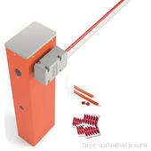
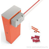
Шлагбаумы NICE: Тумба шлагбаума NICE WIDEM предназначена для проездов шириной до 4 метров. Напряжение питания двигателя 24 В. Скорость открывания 3,5 м/с, интенсивность 300 циклов/час. Габаритные размеры тумбы 1000х320х205 мм.
Удобный для установщика:
- Простая установка и настройка;
- Монтажное основание поставляется в комплекте;
- Встроенный блок управления;
- Программирование функций при помощи diр-переключателей;
- Разъем SM для подключения радиоприемников (SMXI, SMXIS, DXI).
Функциональный для пользователя:
- Программируемое время автоматического закрытия;
- Автоматическое закрытие после срабатывания фотоэлементов;
- Резервное питание от аккумуляторной батареи PS324, устанавливаемой внутри корпуса тумбы шлагбаума (опция);
- Возможность установки фотоэлементов внутри корпуса шлагбаума
- Более мощный редуктор позволяет использовать дополнительные аксессуары для установки на стрелу (решетка WA 13 и подвесная опора WA 12)
Надежный при эксплуатации:
- Прочный корпус из оцинкованной окрашенной стали;
- Удобный и защищенный механизм разблокировки.
Варианты стрел:
- NICE XBA14. Овальная стрела длиной 4,15 метров
- NICE XBA15. Овальная стрела длиной 3,15 метров
- NICE XBA19. Овальная стрела из окрашенного алюминия 45x58x4200 мм
Технические характеристики NICE WIDEM
- Габариты (мм): 1000x320x205
- Масса (кг): 12.00
- Модель: WIDEM
- Максимальная длина стрелы (приобретается отдельно), м: 4
- Интенсивность использования, циклов/час: 300
- Максимальная скорость, м/с: 3.5
- Напряжение питания, B: 230
- Напряжение питания мотора, В: 24
- Максимальный потребляемый ток, А: 1.3
- Максимальная мощность, Вт: 300
- Крутящий момент, Нм: 140
- Степень защиты: IP44
- Диапазон рабочих температур, °С: от -20 до +50
- Габаритные размеры тумбы шлагбаума, мм: 1000х320х205
- Производитель: NICE
Написать отзыв
Ваше имя:
Ваш отзыв:
Примечание: HTML разметка не поддерживается! Используйте обычный текст.
Оценка: Плохо
Хорошо
Введите код, указанный на картинке:


Горячие предложения
- СПЕЦПРЕДЛОЖЕНИЕ на шлагбаум WIDES4KIT — 58445 руб.
- СКИДКА на пульты FLO2RS от 10 шт. — 900 рублей
- СПЕЦПРЕДЛОЖЕНИЕ Комплект WIngo2024KCE — 35345 руб.
- СНИЖЕНА ЦЕНА на комплект RD400KCE — 19175 руб.
- Главная
- ШЛАГБАУМЫ
Шлагбаумы Nice серии Wide в модификации S, M и L
Надежные шлагбаумы серии Nice Wide для интенсивной работы и проемов шириной до 7 м. Идеально подходит для общественных и жилых зданий, а также для коммерческих и промышленных предприятий. Быструю и надежную работу шлагбаума обеспечивает двигатель 24В.

бюджетная модель для проезда 4 м. Встроенный блок управления. Напряжение питания мотора 24В. Мощность 300 Вт. Работоспособность 100 цикл/час.
58 445 руб.
для проезда 4 м. Стрела 4 м алюминиевая. Напряжение питания 24В. Встроенный блок управления, разъем SM для приемников, дип-переключатели. Интенсивность работы 300 цикл/час. Открывание проезда 4 м за 3,5 сек.
63 065 руб.
комплект шлагбаума для проезда 5 м. Стрела овальная 5,15 м. Питание 24В. Мощность 300 Вт. Открывание за 4 сек, интенсивность 100 цикл/час. Встроенный блок управления, настройка дип-переключателями.
67 685 руб.
для проезда 6 м. Стрела составная 6 м (3,15+3,15 м). Модель эконом-класса. Питание 24В, мощность 360 Вт. Производительность системы 200 цикл/час. Дип-переключатели, разъем SM для радиоприемников.
98 485 руб.

для широких проездов до 7 м. Стрела 7 м (3,15 + 4,15 с соединителем) составная, овальная. Питание 24В. Производительность 200 цикл/час, время открывания 5 сек. Комплект: тумба, стрела, демпфер, наклейки.
107 725 руб.
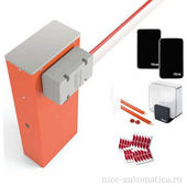
для широких проездов до 7 м. Стрела 7 м (3,15 + 4,15 с соединителем) составная, овальная. Питание 24В. Производительность 200 цикл/час, время открывания 5 сек. Комплект: тумба, приемник, стрела, демпфер, наклейки, фотоэлементы, лампа.
113 115 руб.
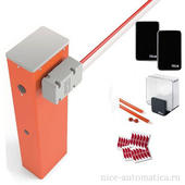
Комплект : тумба шлагбаума, стрела 45х58х4000 мм XBA19, демпфер защитный на рейку XBA13, наклейки светоотражающие NK1,встроенный радиоприемник, фотоэлементы Medium EPM, сигнальная лампа ELDC. Оптимальный вариант для бюджетной системы автоматизации въезда во двор, на небольшую парковку.
63 835 руб.
Комплект: тумба, стрела, наклейки, защитный демпфер, радиоприемник, фотоэлементы, сигнальная лампа. Для проезда 4 м. Стрела 4 м алюминиевая. Напряжение питания 24В. Встроенный блок управления. Интенсивность работы 300 цикл/час. Открывание проезда 4 м за 3,5 сек.
63 835 руб.
Комплект: тумба, стрела, защитный демпфер, наклейки, фотоэлементы, приемник, сигнальная лампа. Питание 24В. Интенсивность работы 300 цикл/час.
68 455 руб.
для проезда 6 м. Стрела овальная XBA-6RU длиной 6,2 м. радиоприемник встроенный, сигнальная лампа и фотоэлементы EPM, питание системы 24В, мощность 360 Вт. Выполнение 200 циклов открывания / закрывания в час.
103 875 руб.

Инструкции по установке приводов Nice (Италия)
Приводы Nice для гаражных секционных ворот
 Электроприводы Nice SHEL50-75
Электропривод Nice Spin
Электропривод SP6100
Электропривод Spin11
Электропривод Spin11 кратка€ инстр.
Электропривод CLIMBER_RO1124
Электропривод Sumo
Электропривод Soon
Приводы Nice для откатных ворот
электропривод ROAD400
электроприводы RB600_1000
электропривод ROBO_S (укороченна€)
электропривод RO500
электропривод ROBO
электропривод RUN
электропривод THOR
Приводы Nice для распашных ворот
Электроприводы WINGO 2024-3524
Электроприводы HYPPO
Электроприводы WINGO
Электроприводы MB4005
Электроприводы MB5016
Электроприводы MOBY_S
Электроприводы POP
Электроприводы WALKY
Электропривод TOONA
Автоматические шлагбаумы Nice
Шлагбаумы Signo
Шлагбаумы Signo sia20
Шлагбаумы WIL
Шлагбаумы Wil управление..
Шлагбаум X-Bar
Блоки управления Nice
A500
A6-A6F-A700F
A60
A6F_A700F_S
A824
A924
MC824H
MC424
POA1
SNA1_A _SPIN11
Радиоуправление Nice
Приемник SMXI
Приемники FloxiR_Floxi2R_S
Пульты дистанционного управлени€
Радиоуправление серии FLOR и VERY
FLO_VERY
Приемник Nice One OX OXI
Приемник TT1N
Аксессуары Nice
Фотоэлементы FE-FEP-FI-BF
Фотоэлементы MOFB
Кодовая панель MOTB_rus.pdf