|
|
|

- Производится
- Тип: портативный электрокардиограф
- Дисплей: жидкокристаллический, с отображением до 12 ЭКГ отведений
- Количество каналов: 3-канальный
- Интерпретация: анализ по 12 отведениям одновременно
- Цифровая клавиатура
- В наличии на складе в Москве
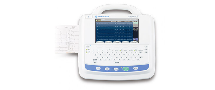
Электрокардиограф Cardiofax C ECG-2150 японского бренда Nihon Kohden – прекрасное решение для работы с пациентом и возможность расширить анализ. Представляя собой 3-канальный аппарат ЭКГ с компактным корпусом и современным жидкокристаллическим дисплеем, Cardiofax C ECG-2150 будет удобен даже для пользователя-новичка.
Электрокардиограф имеет специальную программу измерения ЭКГ, программу анализа и интерпретации ЭКГ. В устройстве Cardiofax C ECG-2150 предусмотрен стандартный функционал со всеми необходимыми возможностями для проведения качественного обследования пациента.
Двенадцать отведений ЭКГ отображаются на экране аппарата одновременно. При этом гарантируется высокая четкость изображения на жидкокристаллическом дисплее. За счет отображения 12 отведений удается принимать оптимальные решения о необходимости печати полученных результатов.
Особенности модели Cardiofax C ECG-2150
- Возможность предварительной проверки качества ЭКГ перед печатью в целях экономии термобумаги.
- Высокая точность и качество печати благодаря термопринтеру с высоким разрешением.
- Комбинированное питание: электрокардиограф может работать от батареи или от сети.
- Возможность хранения до 3000 файлов ЭКГ на SD.
- хранящиеся на внешней карте памяти SD
- Возможность регистрации ЭКГ в автоматическом или ручном режиме.
- Удобная транспортировка за счет легкого веса и компактных размеров аппарата, а также специальной сумки для переноски (опция).
- Максимально точная диагностика.
Электрокардиограф Cardiofax C ECG-2150 соответствует стандарту IEC 60601-2-51 и полностью отвечает требованиям специалистов к качеству и производительности.
Технические характеристики
Обратите внимание на таблицу, где представлены основные технические характеристики и параметры электрокардиографа:
|
Дисплей |
|
|
Функция предварительного просмотра |
есть |
|
Вес |
1,7 кг |
|
Время работы от батареи |
120 минут |
|
Частота дискретизации |
8000 |
|
Защита дефибрилляции |
есть |
|
Чувствительность |
10 mm/mV ±2% |
|
Передача данных |
SD, LAN |
|
Количество каналов |
1, 2, 3 |
|
Скорость печати |
25, 50 mm/s |
|
Термопринтер |
63 мм |
|
Время зарядки аккумулятора |
в течение 10 часов |
|
Возраст пациентов |
от 3 лет |
|
Программа измерения ЭКГ |
есть |
|
Программа интерпретации ЭКГ |
есть |
|
Параметры |
279 (W) x 75 (H) x 210 (L) mm ±10% |
|
Регистрация ЭКГ |
|
|
Вывод на печать |
3-канальный |
Дополнительно:
- Кейс для транспортировки электрокардиографа
- Тележка
Базовая комплектация
|
Название |
Количество |
|
Электрокардиограф |
1 |
|
USB A type USB1.1 |
1 |
|
SD slot |
1 |
|
LAN port |
1 |
micro
Электрокардиограф Nihon Kohden Cardiofax C ECG-2150 (Япония)
")
 » itemprop=»image» alt=»»>
![]()
Cardiofax C — электрокардиограф, разработанный для поддержки клинической диагностической ЭКГ с высококачественным анализом для надежной диагностики. Cardiofax C использует проверенную интерпретирующую программу ECAPS12C и предоставляет отчет анализа двенадцати канальной ЭКГ с 200 распознаваемыми элементами и алгоритмами подавления артефакта.
Предоставляя необходимые данные для точной диагностики, Cardiofax C — идеальное решение для медицинских учреждений, клинической и частной лечебной практики.
Ключевые параметры
— Большой дисплей для двенадцати канального вывода данных с целью предварительного сбора и подтверждения.
— Интегрированный трехканальный термограф.
— Надежная диагностика с помощью передовой аналитической программы (ECAPS12C).
— Большая емкость встроенной памяти с возможностью расширения посредством SD-карты.
— Подключение W-LAN для электронной передачи данных на ПК.
— Дополнительная программа для управления, отчетности и архивирования на ПК (polaris.one).
— Подключение считывателя штрих-кода для легкого и безопасного управления данными.
— Портативность за счет малого веса и размера и продолжительного времени работы от батареи.
— Соответствие стандарту IEC 60601-2-25:2011 для улучшенной фильтрации сигналов и большей точности автоматических измерений.
Skip to content
Электрокардиографы
Общая информация
Серия электрокардиографов Cardiofax компании Nihon Kohden отличается простотой эксплуатации и эффективностью рабочих процессов. Cardiofax S разработан в помощь медицинскому персоналу, предоставляя точную и надежную информацию ЭКГ. 7-дюймовый дисплей с подсветкой выводит все необходимые данные и 12 отведений ЭКГ на один экран.
Руководство, выводимое на экран, помогает оптимально позиционировать электроды, поддерживая эффективность работы специалистов, осуществляющих уход за больным. Доступны другие эффективные инструменты, такие как считыватель штрих-кода или считыватель магнитных карт для ввода идентификационной информации пациента. Cardiofax S поддерживает бумажный и безбумажный документооборот с передачей графиков и результатов анализа на ПК для просмотра.
Усовершенствованная программа интерпретации – программа анализа ECAPS 12C — обеспечивает скорость и достоверность диагностики пациентов. Аппарат одновременно собирает и анализирует 12 отведений ЭКГ с 200 распознаваемыми элементами и активным подавлением шума.
Ключевые параметры
- Легкий и компактный, легко транспортируется за ручку, с аккумулятором для высокой автономности.
- Интегрированный 3/6-канальный термопринтер
- Функция предварительного просмотра перед печатью.
- Надежная диагностика с помощью передовой аналитической программы (ECAPS12C).
- Большая емкость встроенной памяти с возможностью расширения посредством SD-карты.
- Подключение по локальной сети и (или) W-LAN для электронной передачи данных.
- Дополнительная программа для управления, отчетности и архивирования на ПК (polaris.one).
- Экспорт данных в стандартные форматы (PDF, XML, DICOM и т. д.).
- Сoответствие стандарту IEC 60601-2-25:2011 для улучшенной фильтрации сигналов и большей точности автоматических измерений.
CONTENTS |
||
|
Contents |
||
|
Conventions Used in this Manual and Instrument ………………………………………………………….. |
i |
|
|
Warnings, Cautions and Notes …………………………………………………………………………… |
i |
|
|
Explanations of the Symbols in this Manual and Instrument …………………………………… |
i |
|
|
Section 1 |
General ………………………………………………………………………. |
1C.1 |
|
Introduction ………………………………………………………………………………………………………….. |
1.1 |
|
|
Service Policy ………………………………………………………………………………………………………. |
1.2 |
|
|
Specifications ………………………………………………………………………………………………………. |
1.3 |
|
|
Panel Description ………………………………………………………………………………………………….. |
1.5 |
|
|
ECG-9010K Electrocardiograph ………………………………………………………………………. |
1.5 |
|
|
Top View …………………………………………………………………………………………….. |
1.5 |
|
|
Operation Panel…………………………………………………………………………………… |
1.6 |
|
|
Right Side Panel …………………………………………………………………………………. |
1.7 |
|
|
ECG-9020K/P Electrocardiograph …………………………………………………………………… |
1.8 |
|
|
Top View …………………………………………………………………………………………….. |
1.8 |
|
|
Operation Panel…………………………………………………………………………………… |
1.9 |
|
|
Right Side Panel ……………………………………………………………………………….. |
1.10 |
|
|
ECG-9022K Electrocardiograph …………………………………………………………………….. |
1.11 |
|
|
Top View …………………………………………………………………………………………… |
1.11 |
|
|
Operation Panel…………………………………………………………………………………. |
1.12 |
|
|
Right Side Panel ……………………………………………………………………………….. |
1.13 |
|
|
Composition ……………………………………………………………………………………………………….. |
1.14 |
|
|
ECG-9010K Electrocardiograph …………………………………………………………………….. |
1.14 |
|
|
ECG-9020K Electrocardiograph …………………………………………………………………….. |
1.15 |
|
|
ECG-9020P Electrocardiograph …………………………………………………………………….. |
1.16 |
|
|
ECG-9022K Electrocardiograph …………………………………………………………………….. |
1.17 |
|
|
Location ……………………………………………………………………………………………………………… |
1.18 |
|
|
Block Diagram …………………………………………………………………………………………………….. |
1.19 |
|
|
Connection Diagram …………………………………………………………………………………………….. |
1.20 |
|
|
Section 2 |
Maintenance ………………………………………………………………. |
2C.1 |
|
Replacement ………………………………………………………………………………………………………… |
2.1 |
|
|
Periodic Replacement Schedule ……………………………………………………………………… |
2.1 |
|
|
Cleaning ………………………………………………………………………………………………………………. |
2.2 |
|
|
Cleaning and Greasing Schedules…………………………………………………………………… |
2.2 |
|
|
Cleaning the Paper Mark Sensor and Paper Empty Sensor …………………………………. |
2.2 |
|
|
Cleaning the Motor Rotation Sensor and |
||
|
Greasing the Motor Gear and Gear Meshed with Motor Gear ………………………………. |
2.3 |
|
|
Section 3 Troubleshooting and System Error Message ……………… |
3C.1 |
|
|
Troubleshooting Flowchart ………………………………………………………………………………………. |
3.1 |
|
|
Troubleshooting Table …………………………………………………………………………………………….. |
3.4 |
|
Service Manual ECG-9010/9020 Rev B |
C.1 |
|
CONTENTS |
|
|
Troubleshooting General Operation Problem……………………………………………………… |
3.4 |
|
Troubleshooting Recording Problem ………………………………………………………………… |
3.6 |
|
System Error Message …………………………………………………………………………………………… |
3.7 |
|
Section 4 |
System Test, Adjustment and Setting………………………….. |
4C.1 |
|
System Test …………………………………………………………………………………………………………. |
4.1 |
|
|
Overall ………………………………………………………………………………………………………… |
4.1 |
|
|
Calling up the Test Level 1 …………………………………………………………………………….. |
4.2 |
|
|
Calling up the Test Level 2 …………………………………………………………………………….. |
4.3 |
|
|
Entering the System Test Number …………………………………………………………………… |
4.4 |
|
|
Executing the System Test ……………………………………………………………………………. |
4.5 |
|
|
Quitting the System Test ……………………………………………………………………………….. |
4.6 |
|
|
Exiting the System Test Mode ……………………………………………………………………….. |
4.6 |
|
|
Demonstration ………………………………………………………………………………………………………. |
4.7 |
|
|
Recorder ………………………………………………………………………………………………………………. |
4.8 |
|
|
Thermal Head ……………………………………………………………………………………………………… |
4.11 |
|
|
Key ……………………………………………………………………………………………………………………. |
4.12 |
|
|
Memory ……………………………………………………………………………………………………………… |
4.13 |
|
|
Single Memory Test Mode ……………………………………………………………………………. |
4.14 |
|
|
Continuous Memory Test Mode …………………………………………………………………….. |
4.14 |
|
|
LCD/LED ……………………………………………………………………………………………………………. |
4.15 |
|
|
Input Unit …………………………………………………………………………………………………………… |
4.17 |
|
|
Calibration ………………………………………………………………………………………………………….. |
4.18 |
|
|
Communication …………………………………………………………………………………………………… |
4.19 |
|
|
CRO/EXT1 …………………………………………………………………………………………………………. |
4.21 |
|
|
System Setup Initialization …………………………………………………………………………………… |
4.23 |
|
|
ECG Findings List Recording ………………………………………………………………………………… |
4.24 |
|
|
Recording Resolution Setting ………………………………………………………………………………… |
4.25 |
|
|
Cue Mark Adjustment …………………………………………………………………………………………… |
4.26 |
|
|
Date and Time Setting ………………………………………………………………………………………….. |
4.28 |
|
|
Setting the Date and Time ………………………………………………………………….. |
4.28 |
|
Section 5 |
Board/Unit Description …………………………………………………. |
5C.1 |
|
Block Diagram ……………………………………………………………………………………………………… |
5.1 |
|
|
Power Unit…………………………………………………………………………………………………………… |
5.2 |
|
|
ECG Control Board ………………………………………………………………………………………………. |
5.2 |
|
|
Flash ROM Board ………………………………………………………………………………………………… |
5.3 |
|
|
Inverter Board ……………………………………………………………………………………………………… |
5.3 |
|
Section 6 Disassembly and Assembly ………………………………………….. |
6C.1 |
|
Before You Begin ………………………………………………………………………………………………….. |
6.1 |
|
Warnings and Cautions ……………………………………………………………………………….. |
6.1 |
|
Required Tools ……………………………………………………………………………………………. |
6.1 |
|
Board and Unit Location ………………………………………………………………………………. |
6.2 |
|
Cable Connection ……………………………………………………………………………………….. |
6.3 |
|
Removing the Top Casing ……………………………………………………………………………………….. |
6.4 |
|
C.2 |
Service Manual ECG-9010/9020 Rev B |
|
CONTENTS |
||
|
Removing the LCD Assy ………………………………………………………………………………………… |
6.5 |
|
|
Removing the Thermal Head Assy …………………………………………………………………………… |
6.6 |
|
|
Removing the Motor Assy ………………………………………………………………………………………. |
6.8 |
|
|
Removing the Speaker Assy …………………………………………………………………………………… |
6.9 |
|
|
Removing the Inverter Board ………………………………………………………………………………… |
6.10 |
|
|
Removing the ECG Control Board ………………………………………………………………………….. |
6.11 |
|
|
Removing the Power Unit ……………………………………………………………………………………… |
6.12 |
|
|
Replacing the Thermistor and Termistor Cable …………………………………………………. |
6.14 |
|
|
Removing the Battery Terminal Assy ………………………………………………………………………. |
6.15 |
|
|
Removing the Magazine Assy ……………………………………………………………………………….. |
6.16 |
|
|
Removing the Bottom Casing ………………………………………………………………………………… |
6.17 |
|
|
Replacing the Fuse on the Power Board ………………………………………………………………….. |
6.18 |
|
|
Replacing the Lithium Battery on the ECG Control Board …………………………………………… |
6.19 |
|
|
Section 7 |
Replaceable Parts List………………………………………………… |
7C.1 |
|
General Parts List …………………………………………………………………………………………………. |
7.2 |
|
|
Top Casing Assy …………………………………………………………………………………………………… |
7.4 |
|
|
Top Casing Assy, RK-0007 for ECG-9010K ………………………………………………………. |
7.4 |
|
|
Top Casing Assy, RK-0009 for ECG-9020K ………………………………………………………. |
7.5 |
|
|
Top Casing Assy, RK-0044 for ECG-9020P ………………………………………………………. |
7.6 |
|
|
Top Casing Assy, RK-0058 for ECG-9022K ………………………………………………………. |
7.7 |
|
|
Thermal Head Assy, YZ-011H8 ……………………………………………………………………………….. |
7.8 |
|
|
Motor Assy, GC-0011 …………………………………………………………………………………………….. |
7.9 |
|
|
Speaker Assy, RK-0005 ……………………………………………………………………………………….. |
7.10 |
|
|
Magazine Assy, RH-0001 ……………………………………………………………………………………… |
7.11 |
|
|
Battery Terminal Assy, RK-0006 …………………………………………………………………………….. |
7.12 |
|
|
LCD Assy, VL-0001 ……………………………………………………………………………………………… |
7.13 |
|
|
Patient Cable Hanger ……………………………………………………………………………………………. |
7.14 |
|
|
Section 8 |
Connector Pin Assignment ………………………………………… |
8C.1 |
|
Power Unit ……………………………………………………………………………………………………………. |
8.1 |
|
|
CN11 (to AC Inlet) ………………………………………………………………………………………… |
8.1 |
|
|
CN21 (to ECG control board) ………………………………………………………………………….. |
8.1 |
|
|
CN31 (to Thermal Head) ………………………………………………………………………………… |
8.1 |
|
|
CN51 (to Battery) …………………………………………………………………………………………. |
8.1 |
|
|
ECG Control Board ………………………………………………………………………………………………… |
8.2 |
|
|
CNJ011 (to Thermal Head) …………………………………………………………………………….. |
8.2 |
|
|
CNJ012 (to Inverter Board) ……………………………………………………………………………. |
8.2 |
|
|
CNJ013 (to LCD) ………………………………………………………………………………………….. |
8.3 |
|
|
CNJ021 (to Flash ROM Board) ……………………………………………………………………….. |
8.3 |
|
|
CNJ031 (to SIO Connector) …………………………………………………………………………… |
8.5 |
|
|
CNJ032 (to Key Connector) ……………………………………………………………………………. |
8.5 |
|
|
CNJ033 (to Speaker) …………………………………………………………………………………….. |
8.6 |
|
|
CNJ035 (to Power Unit) …………………………………………………………………………………. |
8.7 |
|
|
CNJ036 (to Motor) ………………………………………………………………………………………… |
8.8 |
|
|
CNJ041 (to CRO Connector) ………………………………………………………………………….. |
8.8 |
|
|
CNJ043 (to EXT INPUT Connector) ………………………………………………………………… |
8.8 |
|
Service Manual ECG-9010/9020 Rev B |
C.3 |
CONTENTS
|
CNJ091 (to ECG Connector) ………………………………………………………………………….. |
8.9 |
|
Flash ROM Board ………………………………………………………………………………………………… |
8.10 |
|
CNJ021 (to ECG Control Board) ……………………………………………………………………. |
8.10 |
|
Inverter Board …………………………………………………………………………………………………….. |
8.12 |
|
CN1 (to ECG Control Borad) ………………………………………………………………………… |
8.12 |
|
CN2 (to LCD module) ………………………………………………………………………………….. |
8.12 |
|
External Input/Output Socket ………………………………………………………………………………… |
8.13 |
|
SIO Socket ……………………………………………………………………………………………….. |
8.13 |
|
EXT Input and CRO Output ………………………………………………………………………….. |
8.13 |
|
C.4 |
Service Manual ECG-9010/9020 Rev B |

Conventions Used in this Manual and Instrument
Warnings, Cautions and Notes
Warnings, cautions and notes are used in this manual to alert or signal the reader to specific information.
WARNING
A warning alerts the user to the possible injury or death associated with the use or misuse of the instrument.
CAUTION
A caution alerts the user to possible injury or problems with the instrument associated with its use or misuse such as instrument malfunction, instrument failure, damage to the instrument, or damage to other property.
NOTE
A note provides specific information, in the form of recommendations, prerequirements, alternative methods or supplemental information.
Explanations of the Symbols in this Manual and Instrument
The following symbols found in this manual/instrument bear the respective descriptions as given.
Cardiograph
|
Attention, consult |
Input terminal for analog |
Type CF applied part |
||
|
operator’s manual |
signal |
|||
|
Equipotential terminal |
Output terminal for analog |
The CE mark is a protected |
||
|
signal |
conformity mark of |
|||
|
European Community. |
||||
|
The products herewith |
||||
|
comply with the |
||||
|
Serial input/output terminal |
Eject (magazine release |
requirements of the |
||
|
button) |
Medical Device Directive |
|||
|
93/42/EEC. |
||||
|
Service Manual ECG-9010/9020 Rev A |
i |

Operation panel (for ECG-9010K onlly)
|
Alternating current |
Age |
Filter |
|
|
“On” only for a part of |
REST/PERIODIC |
Copy |
|
|
equipment |
recording |
||
|
“Off” only for a part of |
Paper speed |
Calibration |
|
|
equipment |
|||
|
Battery charging (lamp/on |
Gain |
START/STOP recording |
|
|
screen) |
|||
|
Battery check (lamp/on |
Paper feed |
Automatic control |
|
|
screen) |
|||
|
QRS sync lamp |
Mark |
Manual control |
Operation panel (for ECG-9020K only)
|
Alternating current |
Age |
Filter |
|
|
“On” only for a part of |
Sex |
Copy |
|
|
equipment |
|||
|
“Off” only for a part of |
Mode |
Calibration |
|
|
equipment |
|||
|
Battery charging (lamp/on |
Rhythm |
START/STOP recording |
|
|
screen) |
|||
|
Battery check (lamp/on |
Paper feed |
Automatic control |
|
|
screen) |
|||
|
Mark |
Manual control |
|
ii |
Service Manual ECG-9010/9020 Rev A |

Display (for ECG-9020K only)
QRS sync lamp
Patient cable
|
Attention, consult |
Defibrillation-proof |
|||||
|
operator’s manual |
Type CF applied part |
|||||
|
Service Manual ECG-9010/9020 Rev A |
iii |
Section 1 General
|
Introduction ………………………………………………………………………………………………………… |
1.1 |
|
Service Policy …………………………………………………………………………………………………….. |
1.2 |
|
Specifications ……………………………………………………………………………………………………… |
1.3 |
|
Panel Description ………………………………………………………………………………………………… |
1.5 |
|
ECG-9010K Electrocardiograph …………………………………………………………………… |
1.5 |
|
Top View ………………………………………………………………………………………….. |
1.5 |
|
Operation Panel ………………………………………………………………………………… |
1.6 |
|
Right Side Panel ……………………………………………………………………………….. |
1.7 |
|
ECG-9020K/P Electrocardiograph ………………………………………………………………… |
1.8 |
|
Top View ………………………………………………………………………………………….. |
1.8 |
|
Operation Panel ………………………………………………………………………………… |
1.9 |
|
Right Side Panel ……………………………………………………………………………… |
1.10 |
|
ECG-9022K Electrocardiograph …………………………………………………………………. |
1.11 |
|
Top View ………………………………………………………………………………………… |
1.11 |
|
Operation Panel ………………………………………………………………………………. |
1.12 |
|
Right Side Panel ……………………………………………………………………………… |
1.13 |
|
Composition ……………………………………………………………………………………………………… |
1.14 |
|
ECG-9010K Electrocardiograph …………………………………………………………………. |
1.14 |
|
ECG-9020K Electrocardiograph …………………………………………………………………. |
1.15 |
|
ECG-9020P Electrocardiograph …………………………………………………………………. |
1.16 |
|
ECG-9022K Electrocardiograph …………………………………………………………………. |
1.17 |
|
Location …………………………………………………………………………………………………………… |
1.18 |
|
Block Diagram …………………………………………………………………………………………………… |
1.19 |
|
Connection Diagram ………………………………………………………………………………………….. |
1.20 |
|
Service Manual ECG-9010/9020 Rev B |
1C.1 |

1. GENERAL
Introduction
This service manual provides useful information to qualified service personnel to understand, troubleshoot, service, maintain and repair the ECG-9010K, ECG9020K/P and ECG-9022K Electrocardiograph (referred to in this service manual as “the instrument”, “ECG-9010K” or “ECG-9020K” which includes ECG-9020P and ECG-9022K).
All replaceable parts or units of this instrument and its optional units are clearly listed with exploded illustration to help you locate the parts quickly.
The System test, Adjustment and Setting section in this service manual describes the maintenance that should be performed by qualified service personnel. The Maintenance section in the operator’s manual describes the maintenance that can be performed by the user.
The information in the operator’s manual is primarily for the user. However, it is important for service personnel to thoroughly read the operator’s manual and service manual before starting to troubleshoot, service, maintain or repair this instrument. This is because service personnel needs to understand the operation of the instrument in order to effectively use the information in the service manual.
|
Service Manual ECG-9010/9020 Rev B |
1.1 |
![]()
1. GENERAL
Service Policy
Nihon Kohden Corporation’s basic policy for technical service is to replace faulty units, printed circuit boards or parts. We do not support component-level repair of boards and units outside the factory for the following reasons:
•A special facility is necessary to repair multi-layer boards because most of the components on the board are SMD (surface mount devices) and most of the circuits employ a gate array method.
•To fulfill safety certification requirements, a special facility is necessary to verify safety as medical equipment after the power unit is repaired.
NOTE
•When ordering parts or accessories from your nearest Nihon Kohden Corporation’s distributor, please quote the NK code number and part name which is listed in this service manual, and the name or model of the unit in which the required part is located. This will help us to promptly attend to your needs.
•Always use parts and accessories recommended or supplied by Nihon Kohden Corporation to assure maximum performance from your instrument.
|
1.2 |
Service Manual ECG-9010/9020 Rev B |

1. GENERAL
Specifications
|
ECG input |
|
|
Input impedance |
10 MΩ or more |
|
Electrode offset tolerance |
±500 mV or more |
|
Input unit protection |
Isolated and defibrillator protected |
|
Standard sensitivity |
10 mm /mV ±2% |
|
Common mode rejection ratio |
100 dB or more |
|
Frequency response |
0.05 to 150 Hz (– 3 dB or more) |
|
Waveform data processor |
|
|
Sample rate |
500 samples/s (input unit: 8,000 samples/s) |
|
AC line filter |
50/60 Hz, OFF |
|
High-cut filter |
75, 100, 150 Hz |
|
EMG filter |
25/35 Hz |
|
Time constant |
3.2 s or more |
|
Waveform status detection |
Electrode detachment (polarization voltage), |
|
Noise (high frequency) |
|
|
Sensitivity selection |
5, 10 , 20 mm/mV |
LCD (monochrome with CCFT backlight) (for ECG-9020K/P, ECG-9022K only)
|
Size |
5.6 inch |
|
|
Number of dots |
320 × 240 |
|
|
ECG waveform |
3 channel:Real time 12 ECG lead complexes |
|
|
6 channel: 2.5 s |
||
|
Rhythm lead: 10 s |
||
|
Displayed data |
Waveform, patient information, recording settings, |
|
|
operation mode, heart rate, QRS sync mark, error message, |
||
|
electrode detachment, noise |
||
|
Recorder |
||
|
Printing method |
High resolution thermal printer head |
|
|
Printing density |
200 dpi (8 dots/mm) |
|
|
Scanning line density |
1 ms |
|
|
Recording width |
104 mm |
|
|
Number of recording channels |
2, 3, 4, 6 |
|
|
Paper speed |
10, 12.5, 25, 50 mm/s |
|
|
(10 and 12.5 mm/s available for ECG-9020K only) |
||
|
Printed data |
Program type, version, date and time, paper speed, sensitivity, |
|
|
lead name, filter, hospital name, patient information, |
||
|
timing mark, event mark, electrode detachment, noise |
||
|
Mechanical noise |
48 dB or less at paper speed 25 mm/s |
|
|
External input/output |
||
|
External input |
10 mm/0.5 V ±5%, input impedance 100 kΩ or more |
|
|
Signal output |
0.5 V/1 mV ±5%, output impedance 100 Ω or less |
|
|
Serial I/O |
Communication method: |
RS-232C |
|
Baud rate: |
2400, 4800, 9600, 19200, 38400, |
|
|
57600, 115200 |
||
|
Service Manual ECG-9010/9020 Rev B |
1.3 |
1. GENERAL
|
Power requirement |
|||
|
Line voltage |
100 to 127 VAC, 220 to 240 VAC ±10% |
||
|
Line frequency |
50 or 60 Hz |
||
|
Power input |
Up to 120 VA |
||
|
Power consumption |
49 W or less |
||
|
Built-in battery |
Voltage: 12 V |
||
|
(LCT-1912ANK) |
Current consumption: 6A or less |
||
|
Environment |
|||
|
Operating temperature |
10 to 40°C |
||
|
Operating humidity |
25 to 90% RH |
||
|
Operating atmospheric pressure |
70 to 106 kPa |
||
|
Storage duration and temperature |
2 weeks or less: |
−20 to 65°C |
|
|
(Depends on the battery) |
Between 2 weeks and One year: |
−15 to 40°C |
|
|
Over one year: |
−15 to 25°C |
||
|
Storage humidity |
10 to 95% RH (non condensing) |
||
|
Storage atmospheric pressure |
70 to 106 kPa |
||
|
Recording paper storage temperature |
−20 to 50°C |
||
|
Recording paper storage humidity |
25 to 90% RH |
||
|
Electromagnetic compatibility |
Class B |
||
|
Other |
Indoor portable |
Dimensions and weight
|
Dimensions |
280 W × 52 H × |
|
Weight |
ECG-9010K: |
|
ECG-9020K/P: |
|
|
ECG-9022K: |
216 D mm (excluding protrusions) Approx. 1.9 kg (without battery) Approx. 2.1 kg (without battery) Approx. 2.1 kg (without battery)
Safety
Safety standard:
IEC 60601-1 (1988), IEC 60601-1 Amendment 1 (1991), IEC 60601-1 Amendment 2 (1995) IEC 60601-2-25 (1993), IEC 60601-2-25 Amendment 1 (1999)
Type of protection against electric shock:
AC power: Class I
Batty power: Internally powered equipment
Degree of protection against electric shock:
Defibrillator proof type CF applied part when patient cable BJ-901D, BJ-902D or BJ-903D is used
Degree of protection against harmful ingress of water:
Ordinary equipment
Degree of safety of application in the presence of a flammable anaesthetic mixture with air, oxygen or nitrous oxide:
|
Not suitable for use in the presence of a flammable anaesthetic mixture with air, oxygen or |
|
|
nitrous oxide |
|
|
Mode of operation: Continuous |
|
|
Performance |
|
|
Performance standard: IEC 60601-2-51 (2003) |
|
|
1.4 |
Service Manual ECG-9010/9020 Rev B |

1. GENERAL
Panel Description
ECG-9010K
Electrocardiograph
2
1
Name
1.Operation panel
2.Magazine (recording paper container)
3.Magazine release button
|
Service Manual ECG-9010/9020 Rev B |
1.5 |

1. GENERAL
Operation Panel
14 13
18
4
5
6
7
|
15 |
16 |
17 |
8 |
9 |
10 |
|
|
12 |
||||||
|
11 |
Name
4.Battery charge lamp
5.Battery operation lamp
6.AC power lamp
7.POWER key/lamp
8.FEED/MARK key
9.FILTER key/lamp
10.COPY/CAL key/lamp
11.START/STOP key/lamp
12.AUTO/MANUAL key/lamp
13.REST/PERIODIC key/lamp
14.AGE key/lamp
15.SPEED key/lamp
16.GAIN key/lamp
17.LEAD keys/lamp
18.QRS sync lamp
|
1.6 |
Service Manual ECG-9010/9020 Rev B |

1. GENERAL
Right Side Panel
For the  mark, refer to the descriptions for the Right Side Panel in Section 1 “Panel Descriptions” of the ECG-9010K Operator’s Manual.
23
24
25
Name
19.Patient input connector
20.EXT-IN connector
21.CRO-OUT
22.SIO connector
23.AC power cord socket
24.Battery compartment
25.Equipotential ground terminal
|
Service Manual ECG-9010/9020 Rev B |
1.7 |

1. GENERAL
|
ECG-9020K/P |
Top View |
|
|
Electrocardiograph |
||
|
3 |
||
2
4
1
Name
1.Operation panel
2.Magazine (recording paper container)
3.Magazine release button
4.LCD screen
The keyswithes on the ECG-9020P have a name label instead of the symbol.
|
1.8 |
Service Manual ECG-9010/9020 Rev B |

1. GENERAL
Operation Panel
5
6
7
8
|
9 |
10 |
11 |
12 |
13 |
14 |
15
Name
5.Battery charge lamp
6.Battery operation lamp
7.AC power lamp
8.POWER key/lamp
9.MODE key
10 RHYTHM key/lamp
11.FEED/MARK key
12.FILTER key/lamp
13.COPY/CAL key/lamp
14.START/STOP key/lamp
15.AUTO/MANUAL key/lamp
16.F1, F2, F3 function keys
17.AGE key
18.SEX key
|
Service Manual ECG-9010/9020 Rev B |
1.9 |

1. GENERAL
Right Side Panel
For the  mark, refer to the descriptions for the Right Side Panel in Section 1 “Panel Descriptions” of the ECG-9020K or ECG 9020P Operator’s Manual.
23
24
25
Name
19.Patient input connector
20.EXT-IN connector
21.CRO-OUT
22.SIO connector
23.AC power cord socket
24.Battery compartment
25.Equipotential ground terminal
|
1.10 |
Service Manual ECG-9010/9020 Rev B |

ECG-9022K
Electrocardiograph
1. GENERAL
Top View
3
2
4
1
Name
1.Operation panel
2.Magazine (recording paper container)
3.Magazine release button
4.LCD screen
|
Service Manual ECG-9010/9020 Rev B |
1.11 |
![]()
1. GENERAL
Operation Panel
5
6
7
8
|
9 |
10 |
11 |
12 |
13 |
14 |
15
Name
5. Battery charge lamp
6. Battery operation lamp
7. AC power lamp
8. POWER key/lamp
9. MODE key
10 RHYTHM key/lamp
11. FEED/MARK key
12. FILTER key/lamp
13. COPY/CAL key/lamp
14. START/STOP key/lamp
15. AUTO/MANUAL key/lamp
16. F1, F2, F3 function keys
17. AGE key
18. SEX key
|
1.12 |
Service Manual ECG-9010/9020 Rev B |

1. GENERAL
Right Side Panel
For the  mark, refer to the descriptions for the Right Side Panel in Section 1 “Panel Descriptions” of the ECG-9022K Operator’s Manual.
23
24
25
Name
19.Patient input connector
20.EXT-IN connector
21.CRO-OUT
22.SIO connector
23.AC power cord socket
24.Battery compartment
25.Equipotential ground terminal
|
Service Manual ECG-9010/9020 Rev B |
1.13 |

1. GENERAL
Composition
ECG-9010K Electrocardiograph
|
ECG-9010K |
RK-0002 |
Bottom Casing Assy |
||||||
|
RK-0003 |
Internal Parts |
|||||||
|
GC-0011 |
Motor Assy |
|||||||
|
RH-0001 |
Magazine Assy |
|||||||
|
RK-0004 |
Thermal Head Assy |
|||||||
|
RK-0005 |
Speaker Assy |
|||||||
|
RK-0006 |
Battom Terminal Assy |
|||||||
|
RK-0007 |
ECG-9010K Top Casing Assy |
|||||||
|
SC-903D |
Power Unit |
|||||||
|
UT-23561 |
ECG Control Board |
|||||||
|
UT-2357 |
Flash ROM Board |
|||||||
|
(Optional) |
||||||||
|
KD-104E |
Cart |
|||||||
|
KH-801E |
Patinet Cable Hanger |
|||||||
|
DI-106D |
Fixing Plate for Cart |
|||||||
|
YC-901D |
Carrying Case |
|||||||
•To order a replacement assembly above, use the Code No.
•To order a replacement component inside an assembly, refer to “Section 7 Replaceablet Parts List”.
|
1.14 |
Service Manual ECG-9010/9020 Rev B |

1. GENERAL
ECG-9020K Electrocardiograph
|
ECG-9020K |
RK-0002 |
Bottom Casing Assy |
||||||
|
RK-0003 |
Internal Parts |
|||||||
|
GC-0011 |
Motor Assy |
|||||||
|
RH-0001 |
Magazine Assy |
|||||||
|
RK-0004 |
Thermal Head Assy |
|||||||
|
RK-0005 |
Speaker Assy |
|||||||
|
RK-0006 |
Battom Terminal Assy |
|||||||
|
RK-0009 |
ECG-9020K Top Casing Assy |
|||||||
|
SC-903D |
Power Unit |
|||||||
|
UT-23561 |
ECG Control Board |
|||||||
|
UT-2357 |
Flash ROM Board |
|||||||
|
VL-0001 |
LCD Assy |
|||||||
|
(Optional) |
||||||||
|
KD-104E |
Cart |
|||||||
|
KH-801E |
Patinet Cable Hanger |
|||||||
|
DI-106D |
Fixing Plate for Cart |
|||||||
|
YC-901D |
Carrying Case |
|||||||
•To order a replacement assembly above, use the Code No.
•To order a replacement component inside an assembly, refer to “Section 7 Replaceablet Parts List”.
|
Service Manual ECG-9010/9020 Rev B |
1.15 |

1. GENERAL
ECG-9020P Electrocardiograph
|
ECG-9020P |
RK-0002 |
Bottom Casing Assy |
||||||
|
RK-0003 |
Internal Parts |
|||||||
|
GC-0011 |
Motor Assy |
|||||||
|
RH-0001 |
Magazine Assy |
|||||||
|
RK-0004 |
Thermal Head Assy |
|||||||
|
RK-0005 |
Speaker Assy |
|||||||
|
RK-0006 |
Battom Terminal Assy |
|||||||
|
RK-0044 |
ECG-9020P Top Casing Assy |
|||||||
|
SC-903D |
Power Unit |
|||||||
|
UT-23563 |
ECG Control Board |
|||||||
|
UT-23577 |
Flash ROM Board |
|||||||
|
VL-0001 |
LCD Assy |
|||||||
|
(Optional) |
||||||||
|
KD-104E |
Cart |
|||||||
|
KH-801E |
Patinet Cable Hanger |
|||||||
|
DI-106D |
Fixing Plate for Cart |
|||||||
|
YC-901D |
Carrying Case |
|||||||
•To order a replacement assembly above, use the Code No.
•To order a replacement component inside an assembly, refer to “Section 7 Replaceablet Parts List”.
|
1.16 |
Service Manual ECG-9010/9020 Rev B |

1. GENERAL
ECG-9022K Electrocardiograph
|
ECG-9022K |
RK-0002 |
Bottom Casing Assy |
||||||
|
RK-0003 |
Internal Parts |
|||||||
|
GC-0011 |
Motor Assy |
|||||||
|
RH-0001 |
Magazine Assy |
|||||||
|
RK-0004 |
Thermal Head Assy |
|||||||
|
RK-0005 |
Speaker Assy |
|||||||
|
RK-0006 |
Battom Terminal Assy |
|||||||
|
RK-0058 |
ECG-9022K Top Casing Assy |
|||||||
|
SC-903D |
Power Unit |
|||||||
|
UT-23564 |
ECG Control Board |
|||||||
|
UT-2357D |
Flash ROM Board |
|||||||
|
VL-0001 |
LCD Assy |
|||||||
|
(Optional) |
||||||||
|
KD-104E |
Cart |
|||||||
|
KH-801E |
Patinet Cable Hanger |
|||||||
|
DI-106D |
Fixing Plate for Cart |
|||||||
|
YC-901D |
Carrying Case |
|||||||
•To order a replacement assembly above, use the Code No.
•To order a replacement component inside an assembly, refer to “Section 7 Replaceablet Parts List”.
|
Service Manual ECG-9010/9020 Rev B |
1.17 |

1. GENERAL
Location
|
Thermal Head Assy |
LCD Assy (for ECG-9020K/9020P/9022K only) |
|
|
Motor Assy |
Flash ROM Board |
|
|
Inverter Board |
||
|
(for ECG-9020K/9020P/9022K only) |
||
|
Speaker Assy |
ECG Control Board
Power Unit
|
1.18 |
Service Manual ECG-9010/9020 Rev B |

1. GENERAL
Block Diagram
NOTE
The LCD module and inverter board are used for the ECG-9020K,
ECG-9020P and ECG-9022K only.
|
Piezo-electric |
CNA011 |
CNJ032 (2pin) |
||||||||||||||||||||||
|
buzzer |
Flash ROM Board |
|||||||||||||||||||||||
|
Motor, Motor sensor, |
CNA012 |
|||||||||||||||||||||||
|
CNJ036 (12pin) |
||||||||||||||||||||||||
|
Mark sensor |
||||||||||||||||||||||||
|
CNJ011 (80pin) |
||||||||||||||||||||||||
|
Membrane key |
CNJ033 (40pin) |
|||||||||||||||||||||||
|
CNJ021 (80pin) |
||||||||||||||||||||||||
|
LCD module |
CNJ012 (12pin) |
CNJ031 (D-SUB 9pin) |
||||||||||||||||||||||
|
ECG Control Board |
||||||||||||||||||||||||
|
2 pin |
5 pin |
CNA015 |
CNJ013 (6pin) |
|||||||||||||||||||||
|
Inverter board |
CNJ043 (mini jack) |
|||||||||||||||||||||||
|
CNA013 |
CNJ041 (mini jack) |
|||||||||||||||||||||||
|
Thermal head |
CNJ011 (12pin) |
|||||||||||||||||||||||
|
CN11 (3pin) |
CN31 (16pin) |
|||||||||||||||||||||||
|
AC |
||||||||||||||||||||||||
|
Power Unit |
CN021 |
CNJ035 (30pin) |
CNJ091 (D-SUB15pin) |
|||||||||||||||||||||
|
source |
||||||||||||||||||||||||
|
(30pin) |
||||||||||||||||||||||||
SIO
EXT-IN
CRO
Patient Input
CN51 (4pin)
CNA014
Battery
|
Service Manual ECG-9010/9020 Rev B |
1.19 |

1. GENERAL
Connection Diagram
|
Index |
Connector No. |
NK Code No. |
Description |
|
1* |
CNA011 |
543993A |
ZHR-2 speaker cable (L50) |
|
2 |
CNA012 |
544002A |
ZHR-12 motor cable (L120, 65) |
|
3 |
CNA013 |
544029B |
FCN723/DF11(100)/51021(40) |
|
4 |
CNA014 |
544011A |
EHR-4 battery terminal cable (L150) |
|
5 |
CNA015 |
544038A |
51021-0500/51021-0600 (L50) |
*We cannot provide this cable seperately; we can only provide it as part of a complete Speaker assy. Refer to “Speaker Assy” in Section 8.
CNA013
CNA012
CNA015
CNA011
CNA014
|
1.20 |
Service Manual ECG-9010/9020 Rev B |
Section 2 Maintenance
|
Replacement ………………………………………………………………………………………………………. |
2.1 |
|
Periodic Replacement Schedule …………………………………………………………………… |
2.1 |
|
Cleaning …………………………………………………………………………………………………………….. |
2.2 |
|
Cleaning and Greasing Schedules ……………………………………………………………….. |
2.2 |
|
Cleaning the Paper Mark Sensor and Paper Empty Sensor ……………………………… |
2.2 |
|
Cleaning the Motor Rotation Sensor and |
|
|
Greasing the Motor Gear and Gear Meshed with Motor Gear …………………………… |
2.3 |
|
Service Manual ECG-9010/9020 Rev A |
2C.1 |
![]()
2. MAINTENANCE
This section describes the periodic replacement and cleaning of parts which are required to maintain the instrument in good working condition.
Replacement
This subsection only describes replacement schedule for parts that need to be periodically replaced. The actual replacement procedures are described in the section for Disassembly and Assembly. Read the whole “Disassembly and Assembly” section, especially its Warnings and Cautions, before replacing any of the parts described here.
Periodic Replacement
Schedule
To maintain the performance of the instrument, the parts listed in the table below must be periodically replaced by qualified service personnel.
|
Part |
NK Code No. Description Recommendation |
|
LCT-1912ANK |
332543B |
|
KPT-104-8MGF1-NKC 541816 |
|
|
LM32019T |
545946 |
|
Motor ASSY |
GC-0011 |
|
BR2032/1F2 |
390765 |
|
Battery |
* See below. |
|
Thermal head |
After 30 km of |
|
recording |
|
|
LCD Module |
After 10000 hours |
|
Motor ASSY |
After 1000 hours |
Lithium battery ** See below.
*Replace the battery when it cannot last for 30 minutes during battery operation at the temperatures between 20 and30° C.
**Replace the lithium battery on the ECG control board when the No. 08 or 09 system error message appears or after the lithium battery is used for 7 years. The life time of the battery is approx. 7 years.
|
Service Manual ECG-9010/9020 Rev A |
2.1 |

2. MAINTENANCE
Cleaning and Greasing
Cleaning and Greasing
Schedules
Cleaning the Paper Mark
Sensor and Paper Empty
Sensor
This subsection describes the cleaning and greasing procedures for parts that must be cleaned and greased by qualified service personnel. The cleaning procedures for parts that can be cleaned by the user are described in the Operator’s Manual.
To maintain the performance of the instrument, the parts listed in the table below must be regularly cleaned or greased.
|
Part |
Frequency |
Performed by |
|
Instrument (external) |
After each use |
User |
|
Thermal Head |
Once a month |
User |
|
Platen Roller assy |
Once a year |
User |
|
Paper Mark Detection Sensor |
Once a month |
Qualified service personnel |
|
Paper Empty Sensor |
Once a month |
Qualified service personnel |
|
Motor Sensor |
Once a year |
Qualified service personnel |
|
Motor Gear and Gear |
Once a year |
Qualified service personnel |
|
Meshed with Motor Gear |
1.Remove the magazine. The illustration below shows the location of the paper mark sensor and paper empty sensor.
2.Use a piece of cotton moistened with alcohol to clean both sensors.
Paper mark sensor
Paper empty sensor
|
2.2 |
Service Manual ECG-9010/9020 Rev A |

Cleaning the Motor Rotation Sensor and Greasing the Motor Gear and Gear Meshed with Motor Gear
2. MAINTENANCE
1.Detach the top casing from the bottom casing as described in the “Disassembly and Assembly” section.
2.Remove the two screws holding the motor assy to the bottom casing and remove the motor assy.
3.Remove the two screws to expose the motor rotation sensor and photodiode.
|
Motor assy |
Motor rotation sensor and |
|
photodiode |
Motor SENS board
Bottom casing
4.Use a piece of cotton moistened with alcohol to clean the sensor and photodiode.
5.Use a brush to clean the holes in the gear.
|
Service Manual ECG-9010/9020 Rev A |
2.3 |

2. MAINTENANCE
6.Use EM-50L (NK code No. 547712) grease to grease the motor gear and the gear which directly meshes with the motor gear as shown below.
Top view
Motor gear
|
Gear meshed |
Motor |
|
with motor gear |
7.Reattach the MOTOR SENS board to the motor with the two screws.
8.Reattach the motor assy to the bottom casing with the two screws.
9.Reattach the top casing to the bottom casing as described in the “Disassembly and Assembly” section.
|
2.4 |
Service Manual ECG-9010/9020 Rev A |
Section 3 Troubleshooting and
System Error Message
|
Troubleshooting Flowchart ……………………………………………………………………………………. |
3.1 |
|
Troubleshooting Table…………………………………………………………………………………………… |
3.4 |
|
Troubleshooting General Operation Problem ………………………………………………….. |
3.4 |
|
Troubleshooting Recording Problem ……………………………………………………………… |
3.6 |
|
System Error Message ………………………………………………………………………………………… |
3.7 |
|
Service Manual ECG-9010/9020 Rev A |
3C.1 |

3. TROUBLESHOOTING AND SYSTEM ERROR MESSAGE
This section describes how to troubleshoot the instrument, using the following:
—flowchart
—troubleshooting table
—system error messages at power-up
Troubleshooting Flowchart
Use the troubleshooting flowchart to find the possible sources of a problem.
Troubleshooting Flowchart
<ECG-9020K only>
The power LED is on but there is no LCD display.
No
Is the LCD backlight on?
Yes
Is there any response when No any switch is pressed?
Yes
Check the cable connection to the CNJ012 connector on the ECG control board.
Normal
The LCD unit is faulty.
|
Is the cable firmly |
Yes |
The ECG control board is faulty. |
|
|
connected to the CNJ013 |
The Inverter board is faulty. |
||
|
connector on the ECG |
|||
|
control board? |
|||
|
The ECG control board |
|||
|
is faulty. |
|||
|
Service Manual ECG-9010/9020 Rev A |
3.1 |

3. TROUBLESHOOTING AND SYSTEM ERROR MESSAGE
The power of the instrument does not turn on.
|
Does the instrument |
No |
||||||||||||||||||
|
operate during AC |
|||||||||||||||||||
|
power operation? |
|||||||||||||||||||
|
Yes |
|||||||||||||||||||
|
Does the LED of the AC power |
No |
Check the cable connections |
|||||||||||||||||
|
light? |
to the CNJ013 connector on |
||||||||||||||||||
|
the ECG control board and |
|||||||||||||||||||
|
Yes |
|||||||||||||||||||
|
the connector on the Inverter |
|||||||||||||||||||
|
board. |
|||||||||||||||||||
|
The membrane key is faulty. |
|||||||||||||||||||
|
Normal |
|||||||||||||||||||
|
The ECG control board is faulty. |
|||||||||||||||||||
|
The power board is faulty. |
|||||||||||||||||||
|
Check the F0102 battery |
|||||||||||||||||||
|
fuse on the power board. |
|||||||||||||||||||
|
Normal |
|||||||||||||||||||
|
The instrument does not |
|||||||||||||||||||
|
operate during battery |
|||||||||||||||||||
|
power operation. |
No |
The power board is faulty. |
|||||||||||||||||
|
Is the battery charged? |
Charge the battery. |
||||||||||||||||||
|
Yes |
|||||||||||||||||||
|
Check the cable connection |
|||||||||||||||||||
|
to the CN51 connector on |
|||||||||||||||||||
|
the power board. |
|||||||||||||||||||
|
Normal |
|||||||||||||||||||
|
Yes |
|||||||||||||||||||
|
Is the F0102 battery fuse |
Replace the F0102 battery |
||||||||||||||||||
|
on the power board blown?. |
fuse on the power board. |
||||||||||||||||||
|
No |
|||||||||||||||||||
The power unit is faulty.
|
3.2 |
Service Manual ECG-9010/9020 Rev A |

The recorder does not feed the recording paper when the Start switch is pressed.
Does the LED for the Start No switch light up?
Yes
Does the recorder print when the recording paper is manually pulled out from under the thermal head?
Yes
Check the cable connection to the CNJ036 connector on the ECG control board.
Normal
 The motor is faulty.
  The ECG control board is faulty.
3. TROUBLESHOOTING AND SYSTEM ERROR MESSAGE
|
Does the recorder print |
Yes |
||
|
in manual mode? |
|||
|
No |
|||
|
Does the paper empty |
Yes |
||
|
mark blink? |
|||
|
No |
|||
|
The ECG control board is |
|||
|
faulty. |
|||
Normal
Check the cable connection  to the CNJ036 connector
on the ECG control board.
Normal
 The ECG control board is faulty.
 The paper mark sensor is faulty.
|
Service Manual ECG-9010/9020 Rev A |
3.3 |

3. TROUBLESHOOTING AND SYSTEM ERROR MESSAGE
Troubleshooting Table
Use the troubleshooting table to locate, identify and solve a problem in the instrument. The problems are divided into general operation and recording. Each category has its own troubleshooting table for fast and easy troubleshooting.
How to use the troubleshooting table
1.Determine which troubleshooting table to use.
2.In the “Problem” column find the trouble item that matches the problem.
3.Do the action recommended in the “Corrective Action” column.
4.If the problem is not solved, do the action for the next possible cause or criteria.
5.If none of the actions solve the problem, contact your nearest Nihon Kohden dealer.
Troubleshooting General
Operation Problem
|
Problem |
Possible Cause/Criteria |
Action |
|
The power LED lights but there |
Faulty connection to the CN012 |
Check the connection to the CNJ012 |
|
is no display or backlight on the |
or CNJ013 connector on the ECG |
and CNJ013 connector on the ECG |
|
LCD screen. |
control board. |
control board. |
|
Faulty Inverter board. |
Replace the Inverter board. |
|
|
Faulty LCD module. |
Replace the LCD module. |
|
|
The instrument does not operate |
Blown F011 or F012 power unit |
Replace the F011 or F012 power unit |
|
during AC power operation. |
fuse. |
fuse. |
|
Faulty connection to the CN033 |
Check the connection to the CNJ033 |
|
|
or CNJ035 connector on the ECG |
and CNJ035 connector on the ECG |
|
|
control board. |
control board. |
|
|
Damaged power cord. |
Replace the power cord. |
|
|
Faulty power unit. |
Replace the power unit. |
|
|
Faulty ECG control board. |
Replace the ECG control board. |
|
|
Damaged membrane key. |
Replace the membrane key. |
|
|
The instrument does not operate |
The battery is not charged. |
Charge the battery. |
|
on battery power. |
||
|
Blown F051 battery fuse. |
Replace the F051 battery fuse. |
|
|
Damaged battery. |
Replace the battery. |
|
|
Faulty connection to the CNJ033 |
Check the connection to the CNJ033 |
|
|
or CNJ035 connector on the ECG |
and CNJ035 connector on the ECG |
|
|
control board or the CN031 or |
control board and the CN031 and |
|
|
CN051 connector on the power |
CN01 connector on the power unit. |
|
|
unit. |
||
|
3.4 |
Service Manual ECG-9010/9020 Rev A |
 | Manualzz")
Electrocardiograph
ECG-1250
ECG-1250A
ECG-1250K
If you have any comments or suggestions
on this manual, please contact us at:
www.nihonkohden.com
0634-900121C
Copyright Notice
The entire contents of this manual are copyrighted by Nihon Kohden. All rights are reserved. No part of this
document may be reproduced, stored, or transmitted in any form or by any means (electronic, mechanical,
photocopied, recorded, or otherwise) without the prior written permission of Nihon Kohden.
Trademark
The mark printed on the SD memory card that is used in this instrument is a trademark. The company name and model
name are trademarks and registered trademarks of each company.
CONTENTS
1
Contents
2
GENERAL HANDLING PRECAUTIONS ..............................................................................i
WARRANTY POLICY ......................................................................................................... ii
EMC Related Caution ........................................................................................................ iii
Conventions Used in this Manual and Instrument ............................................................. v
Warnings, Cautions and Notes ................................................................................ v
Section 1
General ................................................................................. 1.1
Introduction .................................................................................................................... 1.2
General Information on Servicing ................................................................................... 1.3
Service Policy and Service Parts ................................................................................... 1.5
Service Policy ...................................................................................................... 1.5
Service Parts ....................................................................................................... 1.5
Specifications ................................................................................................................ 1.6
ECG Input .................................................................................................. 1.6
Waveform Data Processor ......................................................................... 1.6
Recorder ..................................................................................................... 1.6
External Input/Output ................................................................................. 1.6
Power Requirement .................................................................................... 1.6
Color LCD (with backlight) .......................................................................... 1.7
Environment ............................................................................................... 1.7
Performance ............................................................................................... 1.7
Dimensions and Weight .............................................................................. 1.7
Safety Standard ......................................................................................... 1.7
Electromagnetic Compatibility .................................................................... 1.8
Panel Descriptions .......................................................................................................... 1.9
Top View ............................................................................................................... 1.9
Operation Panel ................................................................................................... 1.10
Right Side Panel .................................................................................................. 1.11
Rear Panel .......................................................................................................... 1.12
Patient Cable ....................................................................................................... 1.12
Composition .................................................................................................................. 1.13
Location ......................................................................................................................... 1.14
Connector Pin Assignment ............................................................................................ 1.15
EXT-IN/CRO-OUT Connector ............................................................................... 1.15
Block Diagram ............................................................................................................... 1.16
Outline of Operation ...................................................................................................... 1.17
Main Board .......................................................................................................... 1.17
Power Board ........................................................................................................ 1.17
Key Board ........................................................................................................... 1.17
Power ............................................................................................................................ 1.18
Service Manual ECG-1250
C.1
3
4
5
CONTENTS
Section 2
Troubleshooting .................................................................. 2.1
How to Troubleshoot .......................................................................................................
Check Flow for Power Problem ......................................................................................
Operation .......................................................................................................................
Recording .......................................................................................................................
System Information ........................................................................................................
Section 3
2.2
2.3
2.5
2.7
2.8
Maintenance ........................................................................ 3.1
Periodic Replacement Schedule ..................................................................................... 3.3
Cleaning the Parts .......................................................................................................... 3.4
Cleaning the Thermal Head .................................................................................. 3.4
Cleaning the Sensors ........................................................................................... 3.4
Cleaning the Motor and Adding the Grease .......................................................... 3.5
Setting the Date and Time .............................................................................................. 3.6
Saving the System Settings........................................................................................... 3.8
Loading the System Settings ........................................................................................ 3.10
System Test .................................................................................................................. 3.12
Displaying the System Test Screen ..................................................................... 3.12
User Mode ................................................................................................ 3.12
Service Mode ............................................................................................ 3.12
Demonstration Waveform .................................................................................... 3.13
Recorder Test ...................................................................................................... 3.13
Thermal Head Test .............................................................................................. 3.14
Adjust Recording Darkness ................................................................................. 3.15
Key Test .............................................................................................................. 3.15
Memory Test ....................................................................................................... 3.16
LCD/LED Test ...................................................................................................... 3.16
Electrode Input Test............................................................................................. 3.17
ECG Input Circuit Test ......................................................................................... 3.18
CRO/EXR1 Test .................................................................................................. 3.19
USB Test ............................................................................................................. 3.20
Initialize System Settings ................................................................................... 3.20
Display Internal Information ................................................................................ 3.20
Display Model Information ................................................................................... 3.20
Adjust Cue Mark ................................................................................................. 3.20
Load Local Language .......................................................................................... 3.21
Initialize Flash Memory ....................................................................................... 3.21
Display SD Card Information ............................................................................... 3.21
Update Program .................................................................................................. 3.21
Initialize All Memory ............................................................................................ 3.21
Feed Roller Setting .............................................................................................. 3.21
Area Setting ........................................................................................................ 3.21
Adjusting the Recording Darkness ................................................................................ 3.22
Initializing Settings ........................................................................................................ 3.23
Initializing System Settings ................................................................................ 3.23
Initializing All Memory ......................................................................................... 3.23
Displaying the Software Version, Internal Voltage and SD Card Information .................. 3.24
Displaying the Software Version .......................................................................... 3.24
C.2
Service Manual ECG-1250
CONTENTS
Displaying the Internal Voltage ............................................................................ 3.24
Displaying the SD Card Information .................................................................... 3.24
Adjusting the Cue Mark ................................................................................................. 3.25
Changing the Language ................................................................................................. 3.26
Changing the Language to Local Language ......................................................... 3.26
Returning the Language to English ...................................................................... 3.26
Upgrading the Software ................................................................................................. 3.27
Setting the Diameter of the Platen Roller ...................................................................... 3.28
Setting the Area for Wireless LAN ................................................................................. 3.29
Maintenance Check Sheet ............................................................................................ 3.30
Overview ............................................................................................................. 3.30
Operation ............................................................................................................ 3.31
LCD ..................................................................................................................... 3.32
Recorder .............................................................................................................. 3.33
Safety ................................................................................................................. 3.34
Section 4
Disassembly and Assembly .............................................. 4.1
Before You Begin ............................................................................................................ 4.2
Warnings, Cautions and Notes ............................................................................. 4.2
Required Tools ...................................................................................................... 4.2
Connection Diagram ....................................................................................................... 4.3
Removing the Top Case .................................................................................................. 4.4
Attaching the Top Case .............................................................................. 4.4
Removing the Key Board ................................................................................................ 4.5
Attaching the Key Board ............................................................................ 4.6
Removing the Inverter Board ......................................................................................... 4.7
Attaching the Inverter Board ...................................................................... 4.7
Removing the LCD Unit .................................................................................................. 4.8
Attaching the LCD Unit ............................................................................... 4.8
Removing the Main Board .............................................................................................. 4.9
Attaching the Main Board ........................................................................... 4.9
Removing the Thermal Head ......................................................................................... 4.10
Attaching the Thermal Head ...................................................................... 4.10
Removing the Motor Assy ............................................................................................. 4.11
Attaching the Motor Assy .......................................................................... 4.11
Removing the Power Board ........................................................................................... 4.12
Attaching the Power Board ........................................................................ 4.12
Removing the Magazine Assy ....................................................................................... 4.13
Attaching the Magazine Assy ................................................................... 4.13
Removing the Open Button ........................................................................................... 4.14
Attaching the Open Button ........................................................................ 4.14
Removing the Speaker .................................................................................................. 4.15
Attaching the Speaker ............................................................................... 4.15
The Fuse Locations ....................................................................................................... 4.16
Section 5
Replaceable Parts List........................................................ 5.1
Service Manual ECG-1250
C.3
1
2
3
4
5
GENERAL HANDLING PRECAUTIONS
This device is intended for use only by qualified medical personnel.
Use only Nihon Kohden approved products with this device. Use of non-approved products or
in a non-approved manner may affect the performance specifications of the device. This
includes, but is not limited to, batteries, recording paper, pens, extension cables, electrode
leads, input boxes and AC power.
Please read these precautions thoroughly before attempting to operate the instrument.
1. To safely and effectively use the instrument, its operation must be fully understood.
2. When installing or storing the instrument, take the following precautions:
(1) Avoid moisture or contact with water, dust, extreme atmospheric pressure, excessive humidity and temperatures,
poorly ventilated areas, and saline or sulphuric air.
(2) Place the instrument on an even, level floor. Avoid vibration and mechanical shock, even during transport.
(3) Avoid placing in an area where chemicals are stored or where there is danger of gas leakage.
(4) The power line source to be applied to the instrument must correspond in frequency and voltage to product
specifications, and have sufficient current capacity.
(5) Choose a room where a proper grounding facility is available.
3. Before Operation
(1) Check that the instrument is in perfect operating order.
(2) Check that the instrument is grounded properly.
(3) Check that all cords are connected properly.
(4) Pay extra attention when the instrument is in combination with other instruments to avoid misdiagnosis or other
problems.
(5) All circuitry used for direct patient connection must be doubly checked.
(6) Check that battery level is acceptable and battery condition is good when using battery-operated models.
4. During Operation
(1) Both the instrument and the patient must receive continual, careful attention.
(2) Turn power off or remove electrodes and/or transducers when necessary to assure the patient’s safety.
(3) Avoid direct contact between the instrument housing and the patient.
5. To Shutdown After Use
(1) Turn power off with all controls returned to their original positions.
(2) Remove the cords gently; do not use force to remove them.
(3) Remove the power cord from the AC SOURCE socket to isolate the instrument from the AC supply mains.
(4) Clean the instrument together with all accessories for their next use.
6. The instrument must receive expert, professional attention for maintenance and repairs. When the instrument
is not functioning properly, it should be clearly marked to avoid operation while it is out of order.
7. The instrument must not be altered or modified in any way.
8. Maintenance and Inspection
(1) The instrument and parts must undergo regular maintenance inspection at least every 6 months.
(2) If stored for extended periods without being used, make sure prior to operation that the instrument is in perfect
operating condition.
Service Manual ECG-1250
i
(3) Technical information such as parts list, descriptions, calibration instructions or other information is available
for qualified user technical personnel upon request from your Nihon Kohden representative.
9. When the instrument is used with an electrosurgical instrument, pay careful attention to the application and/or
location of electrodes and/or transducers to avoid possible burn to the patient.
10. When the instrument is used with a defibrillator, make sure that the instrument is protected against defibrillator
discharge. If not, remove patient cables and/or transducers from the instrument to avoid possible damage.
WARRANTY POLICY
Nihon Kohden Corporation (NKC) shall warrant its products against all defects in materials and workmanship for one
year from the date of delivery. However, consumable materials such as recording paper, ink, stylus and battery are
excluded from the warranty.
NKC or its authorized agents will repair or replace any products which prove to be defective during the warranty period,
provided these products are used as prescribed by the operating instructions given in the operator’s and service manuals.
No other party is authorized to make any warranty or assume liability for NKC’s products. NKC will not recognize any
other warranty, either implied or in writing. In addition, service, technical modification or any other product change
performed by someone other than NKC or its authorized agents without prior consent of NKC may be cause for voiding
this warranty.
Defective products or parts must be returned to NKC or its authorized agents, along with an explanation of the failure.
Shipping costs must be pre-paid.
This warranty does not apply to products that have been modified, disassembled, reinstalled or repaired without Nihon
Kohden approval or which have been subjected to neglect or accident, damage due to accident, fire, lightning,
vandalism, water or other casualty, improper installation or application, or on which the original identification marks
have been removed.
In the USA and Canada other warranty policies may apply.
CAUTION
United States law restricts this device to sale by or on the order of a physician.
ii
Service Manual ECG-1250
EMC RELATED CAUTION
This equipment and/or system complies with IEC 60601-1-2 International Standard for
electromagnetic compatibility for medical electrical equipment and/or system. However, an
electromagnetic environment that exceeds the limits or levels stipulated in IEC 60601-1-2, can cause
harmful interference to the equipment and/or system or cause the equipment and/or system to fail to
perform its intended function or degrade its intended performance. Therefore, during the operation of
the equipment and/or system, if there is any undesired deviation from its intended operational
performance, you must avoid, identify and resolve the adverse electromagnetic effect before
continuing to use the equipment and/or system.
The following describes some common interference sources and remedial actions:
1. Strong electromagnetic interference from a nearby emitter source such as an authorized radio station
or cellular phone:
Install the equipment and/or system at another location. Keep the emitter source such as cellular
phone away from the equipment and/or system, or turn off the cellular phone.
2. Radio-frequency interference from other equipment through the AC power supply of the equipment
and/or system:
Identify the cause of this interference and if possible remove this interference source. If this is not
possible, use a different power supply.
3. Effect of direct or indirect electrostatic discharge:
Make sure all users and patients in contact with the equipment and/or system are free from direct or
indirect electrostatic energy before using it. A humid room can help lessen this problem.
4. Electromagnetic interference with any radio wave receiver such as radio or television:
If the equipment and/or system interferes with any radio wave receiver, locate the equipment and/or
system as far as possible from the radio wave receiver.
5. Interference of lightning:
When lightning occurs near the location where the equipment and/or system is installed, it may
induce an excessive voltage in the equipment and/or system. In such a case, disconnect the AC power
cord from the equipment and/or system and operate the equipment and/or system by battery power,
or use an uninterruptible power supply.
6. Use with other equipment:
When the equipment and/or system is adjacent to or stacked with other equipment, the equipment
and/or system may affect the other equipment. Before use, check that the equipment and/or system
operates normally with the other equipment.
7. Use of unspecified accessory, transducer and/or cable:
When an unspecified accessory, transducer and/or cable is connected to this equipment and/or
system, it may cause increased electromagnetic emission or decreased electromagnetic immunity.
The specified configuration of this equipment and/or system complies with the electromagnetic
requirements with the specified configuration. Only use this equipment and/or system with the
specified configuration.
Service Manual ECG-1250
iii
Caution - continued
8. Use of unspecified configuration:
When the equipment and/or system is used with the unspecified system configuration different than
the configuration of EMC testing, it may cause increased electromagnetic emission or decreased
electromagnetic immunity. Only use this equipment and/or system with the specified configuration.
9. Measurement with excessive sensitivity:
The equipment and/or system is designed to measure bioelectrical signals with a specified
sensitivity. If the equipment and/or system is used with excessive sensitivity, artifact may appear by
electromagnetic interference and this may cause mis-diagnosis. When unexpected artifact appears,
inspect the surrounding electromagnetic conditions and remove this artifact source.
If the above suggested remedial actions do not solve the problem, consult your Nihon Kohden
representative for additional suggestions.
For EMC compliance, refer to “Specifications - Electromagnetic Compatibility” in the Reference section.
The CE mark is a protected conformity mark of the European Community. The products herewith comply
with the requirements of the Medical Device Directive 93/42/EEC.
The CE mark only applies to the ECG-1250K Electrocardiograph.
NOTE about Waste Electrical and Electronic Equipment (WEEE) directive 2002/96/EEC
For the member states of the European Union only:
The purpose of WEEE directive 2002/96/EEC is, as a first priority, the prevention of waste electrical and
electronic equipment (WEEE), and in addition, the reuse, recycling and other forms of recovery of such
waste so as to reduce the disposal of waste.
Contact your Nihon Kohden representative for disposal at the end of its working life.
iv
Service Manual ECG-1250
Conventions Used in this Manual and Instrument
Warnings, Cautions and Notes
Warnings, cautions and notes are used in this manual to alert or signal the reader to specific information.
WARNING
A warning alerts the user to possible injury or death associated with the use or misuse of the
instrument.
CAUTION
A caution alerts the user to possible injury or problems with the instrument associated with its use
or misuse such as instrument malfunction, instrument failure, damage to the instrument, or damage
to other property.
NOTE
A note provides specific information, in the form of recommendations, prerequirements, alternative
methods or supplemental information.
Service Manual ECG-1250
v
1. GENERAL
Section 1 General
Introduction ........................................................................................................................................................ 1.2
General Information on Servicing ....................................................................................................................... 1.3
Service Policy and Service Parts ....................................................................................................................... 1.5
Service Policy .......................................................................................................................................... 1.5
Service Parts ........................................................................................................................................... 1.5
Specifications .................................................................................................................................................... 1.6
ECG Input ...................................................................................................................................... 1.6
Waveform Data Processor ............................................................................................................. 1.6
Recorder ........................................................................................................................................ 1.6
External Input/Output ..................................................................................................................... 1.6
Power Requirement ........................................................................................................................ 1.6
Color LCD (with backlight) .............................................................................................................. 1.7
Environment .................................................................................................................................. 1.7
Performance .................................................................................................................................. 1.7
Dimensions and Weight ................................................................................................................. 1.7
Safety Standard ............................................................................................................................. 1.7
Electromagnetic Compatibility ........................................................................................................ 1.8
Panel Descriptions ............................................................................................................................................. 1.9
Top View .................................................................................................................................................. 1.9
Operation Panel ...................................................................................................................................... 1.10
Right Side Panel ..................................................................................................................................... 1.11
Rear Panel .............................................................................................................................................. 1.12
Patient Cable .......................................................................................................................................... 1.12
Composition ...................................................................................................................................................... 1.13
Location ............................................................................................................................................................ 1.14
Connector Pin Assignment ................................................................................................................................ 1.15
EXT-IN/CRO-OUT Connector .................................................................................................................. 1.15
Block Diagram .................................................................................................................................................. 1.16
Outline of Operation .......................................................................................................................................... 1.17
Main Board ............................................................................................................................................. 1.17
Power Board ........................................................................................................................................... 1.17
Key Board ............................................................................................................................................... 1.17
Power ................................................................................................................................................................ 1.18
Service Manual ECG-1250
1.1
1
1. GENERAL
Introduction
This service manual provides useful information to qualified service personnel
to understand, troubleshoot, service, maintain and repair the ECG-1250A/K
Electrocardiograph (referred to in this service manual as “the instrument”,
“ECG-1250A/K”).
All replaceable parts or units of this instrument and its optional units are
clearly listed with exploded illustration to help you locate the parts quickly.
The information in the operator’s manual is primarily for the user. However, it
is important for service personnel to thoroughly read the operator’s manual and
service manual before starting to troubleshoot, service, maintain or repair this
instrument. This is because service personnel needs to understand the
operation of the instrument in order to effectively use the information in the
service manual.
1.2
Service Manual ECG-1250
1. GENERAL
1
General Information on Servicing
Note the following information when servicing the instrument.
CAUTION
Safety
• There is the possibility that the outside surface of the instrument,
such as the operation keys, could be contaminated by contagious
germs, so disinfect and clean the instrument before servicing it.
When servicing the instrument, wear rubber gloves to protect
yourself from infection.
• There is the possibility that when the lithium battery is broken, a
solvent inside the lithium battery could flow out or a toxic
substance inside it could come out. If the solvent or toxic
substance touches your skin or gets into your eyes or mouth,
immediately wash it with a lot of water and see a physician.
Liquid ingress
The instrument is not waterproof, so do not install the instrument
where water or liquid can get into or fall on the instrument. If liquid
accidentally gets into the instrument or the instrument accidentally
drops into liquid, disassemble the instrument, clean it with clean
water and dry it completely. After reassembling, verify that there is
nothing wrong with the patient safety checks and function/
performance checks. If there is something wrong with the
instrument, contact your Nihon Kohden representative for repair.
Environmental safeguards
Depending on the local laws in your community, it may be illegal to
dispose of the lithium battery in the regular waste collection. Check
with your local officials for proper disposal procedures.
Disinfection and cleaning
To disinfect the outside surface of the instrument, wipe it with a nonabrasive cloth moistened with any of the disinfectants listed below.
Do not use any other disinfectants or ultraviolet rays to disinfect the
instrument.
- Chlorohexidine gluconate solution:
0.5%
- Benzethonium chloride solution:
0.2%
- Glutaraldehyde solution:
2.0%
- Benzalkonium chloride:
0.2%
- Alkyldiaminoethylglycine hydrochloride: 0.5%
Service Manual ECG-1250
1.3
1. GENERAL
Caution - continued
Transport
• Use the specified shipment container and packing material to
transport the instrument. If necessary, double pack the instrument.
Also, put the instrument into the shipment container after packing
so that the buffer material does not get inside the instrument.
• When transporting a board or unit of the instrument, be sure to use
a conductive bag on. Never use an aluminum bag to transport a
board or unit which a lithium battery is mounted. Also, never use a
styrene foam or plastic bag which generates static electricity to
wrap the board or unit of the instrument.
Handling the instrument
• Because the outside surface of the instrument is made of resin, the
outside surface of the instrument is easily damaged. So when
handling the instrument, remove clutter from around the
instrument and be careful to not damage the instrument or get it
dirty.
• Because most of the boards in the instrument are multilayer boards
with surface mount electrical devices (SMD), when removing and
soldering the electrical devices, a special tool is required. To avoid
damaging other electrical components, do not remove and solder
SMD components yourself.
Measuring and test equipment
Maintain the accuracy of the measuring and test equipment by
checking and calibrating it according to the check and calibration
procedures.
Maintenance
Turn off the power of the instrument before doing maintenance,
cleaning or disinfecting. Otherwise you may get an electrical shock
or the instrument may malfunction.
Preventing infection
Follow the local laws or regulations to prevent infection.
1.4
Service Manual ECG-1250
1. GENERAL
1
Service Policy and Service Parts
Service Policy
Our technical service policy for this instrument is to replace the faulty unit,
board or part or damaged mechanical part with a new one. Do not perform
electrical device or component level repair of the multilayer board or unit. We
do not support component level repair outside the factory for the following
reasons:
• Most of the boards are multilayer boards with surface mount electrical
devices, so the mounting density of the board is too high.
• A special tool or high degree of repair skill is required to repair the multilayer
boards with surface mount electrical devices.
Only disassemble the instrument or replace a board or unit in an environment
where the instrument is protected against static electricity.
As background knowledge for repair, pay special attention to the following:
• You can reduce the repair time by considering the problem before starting
repair.
• You can clarify the source of most of the troubles using the information from
the error massage and troubleshooting in the “Troubleshooting” section of
this manual.
Service Parts
NOTE
When ordering parts or accessories from your Nihon Kohden
representative, please quote the code number and part name which
is listed in this service manual, and the name or model of the unit in
which the required part is located. This will help us to promptly
attend to your needs. Always use parts and accessories
recommended or supplied by Nihon Kohden Corporation to assure
maximum performance from your instrument.
Service Manual ECG-1250
1.5
1. GENERAL
Specifications
ECG Input
Input impedance:
Electrode offset tolerance:
Defibrillation-proof:
Common mode rejection ratio:
Patient leakage current:
≥ 20 MΩ
≥ ±550 mV
Isolated and defibrillator protected only when the following specified patient
cable is connected
Patient cable: BJ-901D, BJ-902D, BJ-903D, BA-901D, BA-903D
Recovery time: ≤ 10 s (IEC 60601-2-25: 1993 51.102 compatible)
≤ –100 dB
≤ 5 × 10⁻⁸ A
Standard sensitivity:
Internal noise:
Interference between channels:
Frequency response:
Sample rate:
10 mm/mV ±5%
≤ 20 μVp-v
≤ –40 dB
150 Hz (≥ 71%, high-cut filter: 150 Hz)
8000 sample/s
Waveform Data Processor
Sample rate:
Response to minimum signal:
EMG filter:
High cut filter:
AC line filter:
Drift filter:
Time constant:
500 samples/s, 1.25 μV/LSB
≤ 20 μVp-v
25, 35 Hz (–3 dB)
75, 100, 150 Hz (–3 dB)
50, 60 Hz
Weak: 0.1 Hz (–20 dB), Strong: 0.1 Hz (–34 dB)
≥ 3.2 s
Recorder
Recording speed accuracy:
Printing density:
Scanning line density:
Number of recording channels:
Paper speed:
Recording paper:
Mechanical noise:
Printed data:
≤ ±5%
200 dpi (8 dots/mm), 320 dot/mm2 (25 mm/s)
1 ms
3, 4, 6
10, 12.5, 25, 50 mm/s
110 mm width, 20 m long Z fold
≤ 48 dB at paper speed 10, 12.5, 25 mm/s
Program type, version, date and time, paper speed, sensitivity, lead name, filter,
Patient information (ID number, sex, age), event mark, electrode detachment,
noise
External Input/Output
External input:
Signal output:
10 mm/0.5 V ±5%, input impedance ≥ 100 kΩ
0.5 V/1 mV ±5%, output impedance ≤ 100 Ω
Power Requirement
Line voltage:
Line frequency:
Power input:
100 to 127 V, 220 to 240 V AC ±10%
50, 60 Hz
120 VA
1.6
Service Manual ECG-1250
1. GENERAL
Battery operation time:
Color LCD (with backlight)
Display size:
Resolution:
Displayed data:
Environment
Operating environment
Temperature:
Humidity:
Atmospheric pressure:
Storage environment
Temperature:
≥ 60 minutes
IEC 60601-2-51: 2003.2 56.7
Under the conditions of operating temperature 25°C, 4 ch recording
5.7 inch
320 × 240 dots
Waveform, patient information, recording settings, operation mode, heart rate,
QRS sync mark, error message, electrode detachment, noise
5 to 40°C (41 to 104°F)
25 to 95% RH (noncondensing)
25 to 80% RH (recording paper)
700 to 1060 hPa
–20 to +65°C (–4 to +149°F)
Other:
–20 to +50°C (–4 to +122°F) (recording paper)
10 to 95% RH
10 to 90% RH (recording paper)
700 to 1060 hPa
Indoor portable
Performance
Performance standard:
IEC 60601-2-51: 2003
Dimensions and Weight
Dimensions:
Weight:
210 W × 69 H × 280 D mm (excluding protrusions)
Approx. 2.0 kg (without battery or recording paper)
Safety Standard
Safety standard:
IEC 60601-1: 1988
Humidity:
Atmospheric pressure:
1
IEC 60601-1 Amendment 1: 1991
IEC 60601-1 Amendment 2: 1995
IEC 60601-2-25: 1993
IEC 60601-2-25 Amendment 1: 1999
IEC 60601-1-1: 2000
IEC 60601-1-2: 2001
C22.2 No.601-1-M90: 1990*
C22.2 No.601-1S1-94:1994*
C22.2 No.601-1-1-94: 1994*
CAN/CSA-C22.2 No.601.1.2-94: 1994*
CAN/CSA-C22.2 No.601.2.25-94: 1994*
* These standards only apply to the ECG-1250A Electrocardiograph.
According to the type of protection against electrical shock:
CLASS I EQUIPMENT (AC Powered)
Internally Powered EQUIPMENT (BATTERY Powered)
Service Manual ECG-1250
1.7
1. GENERAL
According to the degree of protection against electrical shock:
Defibrillator-proof type CF applied part when patient cable BJ-901D, BJ-902D,
BJ-903D, BA-901D or BA-903D is used
According to the degree of protection against harmful ingress of water:
IPX0 (ordinary EQUIPMENT)
According to the degree of safety of application in the presence of FLAMMABLE ANAESTHETIC MIXTURE WITH
AIR, OR WITH OXYGEN OR NITROUS OXIDE:
Equipment not suitable for use in the presence of FLAMMABLE
ANAESTHETIC MIXTURE WITH AIR, OR WITH OXYGEN OR NITROUS
OXIDE
According to the mode of operation:
CONTINUOUS OPERATION
Electromagnetic Compatibility
IEC 60601-1-2: 2001
CAN/CSA C22.2 No.60601-2-51-04: 2004*
ANSI/AAMI EC11-1991*
* These standards only apply to the ECG-1250A Electrocardiograph.
1.8
Service Manual ECG-1250
1. GENERAL
1
Panel Descriptions
Top View
1
2
3
4
5
Name
1. Paper magazine release button
2. Paper magazine (Recording paper container)
3. LCD screen
4. Operation panel
5. Battery compartment
CAUTION
Always install the battery even when the electrocardiograph operates on AC power. Otherwise sudden
power down occurs when an electrode is detached during recording.
Service Manual ECG-1250
1.9
1. GENERAL
Operation Panel
1 2 3 4
5
6
7
8
9
10
11
12
13
14
15
Name
1. POWER key/lamp
2. AC power lamp
3. Battery operation lamp
4. Battery charge lamp
5. Function keys
6. ID key
7. MODE key
8. REVIEW key
9. Keyboard
10. RHYTHM key/lamp
11. FEED/MARK key
12. FILTER key/lamp
13. COPY/1 mV key/lamp
14. START/STOP key/lamp
15. AUTO/MANUAL key/lamp
1.10
Service Manual ECG-1250
1. GENERAL
Right Side Panel
1
1
2
3
Name
1. Patient cable connector
2. EXT-IN/CRO-OUT connector
3. AC power cord socket
WARNING
• Connect only the specified instrument to the electrocardiograph and follow the specified procedure.
Failure to follow this warning may result in electrical shock or injury to the patient and operator, and
cause fire or instrument malfunction.
• When the external instrument does not comply with the IEC 60601-1, use a local purchase medical
isolation transformer unit between the external instrument and the AC socket.
• When connecting the electrocardiograph to other instruments, the connection must comply with IEC
60601-1-1: 2000. Refer to “General Requirements for Connecting Medical Electrical System” in Section
11 in the Operator’s Manual.
CAUTION
Do not use the output signal from the output connector of the electrocardiograph for a synchronization
signal on a defibrillator. There is a time delay between the input signal and output signal. When using
the output signal from the electrocardiograph for the synchronization signal on other instrument, always
consider this time delay.
Service Manual ECG-1250
1.11
1. GENERAL
Rear Panel
1
2
3
4
Name
1. Equipotential grounding terminal
2. SD card slot
3. USB connector type A
4. USB connector type B
Patient Cable
1
2
Name
1. Electrode leads
2. Connector
1.12
Service Manual ECG-1250
1. GENERAL
1
Composition
ECG-1250A
ECG-1250K
(Option)
UT-2415
Main board
UT-24161
Key board full
UT-2417
Power board
RH-0005
Magazine assy
GC-0017
Motor assy
YD-121D
Accessory kit A
YD-122D
Accessory kit B
YD-123D
Accessory kit C
YD-124D
Accessory kit (NKE)
SB-901D
Battery pack
KD-104E
Cart
KH-801E/
KH-100D
Patient cable hanger
BJ-903D
Patient cable
QM-064D/
QM-064DE
SD memory card
Z-101BC
Cardio cream
YZ-041H0
USB-RS232C adapter
YZ-041H1
USB-LAN adapter
YZ-041H2
SD wireless LAN card
QW-100Y
Hyper Isolation Transformer
DI-010D
Strage rack
Locally purchase
• USB hub
• Bar code reader
• Magnetic card reader
Service Manual ECG-1250
1.13
1. GENERAL
Location
Thermal head
Motor assy
Inverter board
LCD
Speaker
Main board
Key board
Power board
1.14
Service Manual ECG-1250
1. GENERAL
1
Connector Pin Assignment
EXT-IN/CRO-OUT
Connector
CAUTION
Do not use the output signal from the output connector of the
electrocardiograph for a synchronization signal on a defibrillator.
There is a time delay between the input signal and output signal.
When using the output signal from the electrocardiograph for the
synchronization signal on other instrument, always consider this
time delay.
Using connector: LGY6502-0900 (Code No. 690584)
Mating connector: MP-012L 3.5 mm φ right angle miniature stereo plug
(Code No. 696346)
Input sensitivity: 10 mm/0.5 V
Input impedance: 100 kΩ or more
Output sensitivity: 0.5 V/1 mV
EXT-IN
CRO-OUT (lead II)
GND
Service Manual ECG-1250
1.15
1.16
AC inlet
Power board
SD card
connector
JTAG
connector
EXT IN
1 ch
AC/DC REG.
11 V
JTAG
AN2
(AN3)
AN0
AN1
x32
AC/BATT
SW control
BATTERY
10 to 14.5 V
BATT. charger
T.H. temp.
int. temp.
x16
3.3 V
2.5 V
1.2 V
BUS
x16
USB I/F
5 V DC/DC
REG.
3.3 V DC/DC
REG.
Sound I/F
SRAM
controller
LCD
controller
RTC I/F
Thermal Head
controller
Mark & Paper
Detect cont
Motor
controller
KEY I/F
PWM DA OUT
FPGA
Linear REG
out
in
3.3 V 1.2 V
1.9 V
2.5 V
ECG A I/F
ECG B I/F
SD card
driver
MN5774
24 V DC/DC
REG. (Head)
FlashROM
16 Mbyte
x16
M62723ML
RESET
circuit
Sensor
BUS
Buffer
SDRAM
16 Mbyte
11 V
ISOLATION
11 V
ISOLATION
BATT. volt.
AD 4 CH
BUS
A/D
USB
controller
EZ-OTG
3.3 V CPU
1.9 V
INSTALL BD1
INSTALL BD2
USB
connector
FUNCTION
USB
connector
HOST
ECG input
connector
Main board
RTC4543SA
RTC
Motor
driver
SRAM
128 Kbyte
contrast
control
x16
Thermal
head
Sensor
Motor
Key board
CRO 1 ch
Back light
module
Color LCD
module
1. GENERAL
Block Diagram
Service Manual ECG-1250
1. GENERAL
1
Outline of Operation
Main Board
The main board consists of the following components.
CPU:
SH7706 (Operating frequency: 25 MHz)
D RAM: 16 MB
Input unit:
• R/L/F/RF/C1 to C6 (10 channel analog signal) is input.
• Converts inputs to digital signal of 8000 samples/second by A/D converter.
ECG data processing unit:
• Processes input signal at 500 samples/second (1.25 μV/LSB).
• Processes hum filter, EMG filter and drift filter.
FPGA unit:
• Controls motor, paper sensor, mark sensor, thermal head, speaker and CRO.
• Processes data from the keyboard.
• Saves file data to external memory.
USB unit:
• USB-serial/USB-LAN adapter can be connected to the unit.
• You can enter the patient information from a bar code reader and magnetic
card reader through the unit.
Other units:
• EXT-IN1 is processed digitally in the A/D converter of the CPU.
• INSTALL BD1/2 or JTAG connector is only used when repairing the board
at the factory.
Power Board
DC voltage is produced in the switching transformer. The AC-DC converter unit
allows automatic switching between AC and battery power. The voltage is
converted to 24 V for the thermal head and 3.3 V/5 V for digital circuits, then
fed to the main board.
Key Board
The key board controls LED blinking in the LED controller and sends
information of the keys to the main board.
Service Manual ECG-1250
1.17
1. GENERAL
Power
When the power key is pressed, the software controls power off to prevent
turning power off during data writing.
If a problem occurs in the system, all the LEDs light and the keys do not work.
Press and hold the POWER key for 5 seconds to turn the power off. When the
power is turned on again, the system information is printed.
NOTE
Normally, do not press and hold the POWER key for 5 seconds.
Pressing and holding the POWER key for 5 seconds turns the power
off even while data is being written. If power is cut off while data is
being written, the file may be damaged and the electrocardiograph
might not operate.
1.18
Service Manual ECG-1250
2. TROUBLESHOOTING
Section 2 Troubleshooting
How to Troubleshoot ...........................................................................................................................................
Check Flow for Power Problem ..........................................................................................................................
Operation ...........................................................................................................................................................
Recording ...........................................................................................................................................................
System Information ............................................................................................................................................
2.2
2.3
2.5
2.7
2.8
Service Manual ECG-1250
2.1
2
2. TROUBLESHOOTING
How to Troubleshoot
This section explains how to locate, identify and solve a problem in the
instrument. The troubleshooting tables in this section are divided into general
problems and error messages.
How to Troubleshoot
1. Determine which troubleshooting table to use.
2. In the “Problem” column, find the trouble item that matches the problem or
error message.
3. Do the first action recommended in the “Action” column.
4. If the problem is not solved, do the next action recommended in the
“Action” column. (If this does not solve the problem, do the next
recommended sections.)
5. If none of the actions solve the problem, contact your Nihon Kohden
distributor or representative.
2.2
Service Manual ECG-1250
2. TROUBLESHOOTING
Check Flow for Power Problem
2
When the POWER lamp is lit but the LCD does not display
No
Yes
The voltage of the CNJ052 connector
(main board) is more than 10.6 V.
The voltage of the CNJ002 connector
(keyboard full) is more than 10.6 V.
Is the backlight on?
Yes
No
Is there a response when
you press the keys?
Main board unit failure.
Inverter board unit failure.
No
Main board unit failure
Yes
Main board unit failure.
Inverter board unit failure.
LCD unit failure
The voltage of the CNJ003 connector (keyboard full) is 3.3 V.
Yes
No
LCD unit failure
Main board unit failure
When the power can’t be turned on
Is the power source AC?
Yes
No
The voltage of the CNJ055
connector (main board) pin
33 is 10 to 14 V.
Is the AC power lamp lit?
Yes
No
Yes
Ten key board failure.
Main board unit failure.
Power board unit failure.
Yes
Charge the battery.
Check the F512 battery fuse of the
power board unit.
Power board unit failure
Yes
No
Yes
The voltage of the
CNJ052 connector (main
board) is more than 3.2 V.
The voltage of the CNJ051
connector (main board) is
10 to 14 V.
No
No
The voltage of the CNJ055
connector (main board) pin
9 to 14 is more than 3.2 V.
No
Is the battery charged?
No
Key board full failure
Yes
The battery fuse
is blown
Replace the fuse.
Power board unit failure
Key board full failure
Main board unit failure
It is normal
Power board unit failure
Service Manual ECG-1250
2.3
2. TROUBLESHOOTING
When there is no response even when the START key is pressed
The light blinks.
No
Is there recording paper in the
machine?
The Start LED is lit.
Put recording paper in the
machine.
Yes
The voltage of the CNJ042 connector
(main board) is more than 4.85 V.
The light is on.
No
Control board unit failure
Yes
Mark detection sensor failure
Recording is abnormal
When pulling the paper, the
waveforms are printed
correctly.
Recording is normal
Check the CNJ052 connector
of the main board unit
CNA001 and CNA002
cable assy failure
It is abnormal
Main board unit failure
It is normal
Motor failure
Main board unit failure
2.4
Service Manual ECG-1250
2. TROUBLESHOOTING
Operation
2
Problem
The power LED lights but there is no
Possible Cause/Criteria
Faulty connections of connectors.
Action
Check the connection to the CNA004
display or backlight on the LCD
and CNA005 connectors on the key
screen.
board, the connectors between inverter
board and LCD unit, and the connector
on the LCD unit.
Faulty inverter board.
Replace the inverter board.
Faulty LCD unit.
Replace the LCD unit.
The instrument does not operate
Damaged power cord.
Replace the power cord.
during AC power operation.
Faulty power board.
Replace the power board.
Faulty main board.
Replace the main board.
Damaged key board.
Replace the key board.
The instrument does not operate on
The battery is not charged.
Charge the battery.
battery power.
Faulty F512.
Replace the F512 on the power board.
Damaged battery.
Replace the battery.
Faulty connection of the battery
Check the connection between
connector.
CNJ511 connector on the power board
and the battery.
No key or switch operation.
Faulty power board.
Replace the power board.
Faulty connections of connectors.
Check the connection between
CNJ052 connector on the main board
and CNJ001 connector on the key
board.
Faulty key board.
Replace the key board.
Faulty main board.
Replace the main board.
The electrocardiograph is affected by
static electricity.
Press the POWER key for 5 seconds to
turn the power off. When the power is
turned on again, the system
information is printed. Show the
information to Nihon Kohden
representative.
The power does not turn off.
The electrocardiograph is affected by
static electricity.
Press the POWER key for 5 seconds to
turn the power off. When the power is
turned on again, the system
information is printed. Show the
information to Nihon Kohden
representative.
Only certain electrode lead waveforms
The electrodes or cables connections
Make sure that all electrodes and
are displayed on the screen or noise
from the patient to the instruments are
cables connections from the patient to
appears on the waveform.
not properly connected.
the instrument are properly connected.
Faulty main board.
Replace the main board.
No electrode lead waveforms are
Electrodes are not attached to the
Make sure that the electrodes are
displayed on the screen or noise
patient.
properly attached to the patient.
appears on all waveforms.
Faulty main board.
Replace the main board.
Service Manual ECG-1250
2.5
2. TROUBLESHOOTING
Problem
Possible Cause/Criteria
Action
Vertical and horizontal strips appear
Faulty connection to the CNJ052
Check the connection to the CNJ052
on the LCD screen at constant
connector on the main board, CNJ001
connector on the main board,
intervals.
and CNJ003 connectors on the key
CNJ001 and CNJ003 connectors on
board.
the key board.
Faulty main board.
Replace the main board.
Faulty LCD unit.
Replace the LCD unit.
Check the connection to the CNJ051
Check the connection to the CNJ051
connector on the main board.
connector on the main board.
Faulty speaker.
Replace the speaker assy.
No sound.
2.6
Service Manual ECG-1250
2. TROUBLESHOOTING
Recording
2
Problem
The recorder does not feed the
Possible Cause/Criteria
Action
Dirty paper mark sensor.
Clean the paper mark sensor.
Faulty connection to the CNJ042
Check the connection to the CNJ042
connector on the main board.
connector on the main board.
Damaged key switch.
Replace the key board.
Faulty main board.
Replace the main board.
Faulty motor.
Replace the motor assy.
The recording paper is fed but there is
Faulty connection to the CNJ043
Check the connection to the CNJ043
no printing.
connector on the main board.
connector on the main board.
Faulty thermal head.
Replace the thermal head.
Faulty power board.
Replace the power board.
Faulty main board.
Replace the main board.
Dirty paper mark sensor.
Clean the paper mark sensor.
Faulty connection to the CNJ042
Check the connection to the CNJ042
connector on the main board.
connector on the main board.
Faulty ECG control board.
Replace the ECG control board.
Faulty paper mark sensor board.
Replace the paper mark sensor board.
Sometimes the recorder does not print
The input protection circuit which
Check the electrode attachment to the
and blank recording paper is fed from
protects the thermal head from strong
patient, and if necessary, re-position
the recorder.
noise, such as hum, is rejecting noisy
the electrodes so that a good ECG
waveforms.
waveform is displayed.
The recording paper tracks zigzag or to
Dirty thermal head.
Clean the thermal head.
one side.
The recording paper is not properly set
Make sure that the recording paper is
in the instrument.
aligned with the lower recording paper
recording paper when the
START/STOP key is pressed.
The paper mark cannot be detected.
guide.
Inaccurate or worn out platen roller.
Service Manual ECG-1250
Replace the magazine assy.
2.7
2. TROUBLESHOOTING
System Information
If a problem occurs in the system, all the LEDs light and keys do not work.
Press the POWER key for 5 seconds to turn the power off. When the power is
turned on again, the system information is printed.
System information example
NOTE
The system information is necessary for repair. Save it.
2.8
Service Manual ECG-1250
3. MAINTENANCE
Section 3 Maintenance
3
Periodic Replacement Schedule ........................................................................................................................ 3.3
Cleaning the Parts ............................................................................................................................................. 3.4
Cleaning the Thermal Head ...................................................................................................................... 3.4
Cleaning the Sensors ............................................................................................................................... 3.4
Cleaning the Motor and Adding the Grease .............................................................................................. 3.5
Setting the Date and Time ................................................................................................................................. 3.6
Saving the System Settings .............................................................................................................................. 3.8
Loading the System Settings ............................................................................................................................ 3.10
System Test ...................................................................................................................................................... 3.12
Displaying the System Test Screen ......................................................................................................... 3.12
User Mode .................................................................................................................................... 3.12
Service Mode ............................................................................................................................... 3.12
Demonstration Waveform ........................................................................................................................ 3.13
Recorder Test .......................................................................................................................................... 3.13
Thermal Head Test .................................................................................................................................. 3.14
Adjust Recording Darkness ..................................................................................................................... 3.15
Key Test .................................................................................................................................................. 3.15
Memory Test ........................................................................................................................................... 3.16
LCD/LED Test ......................................................................................................................................... 3.16
Electrode Input Test ................................................................................................................................ 3.17
ECG Input Circuit Test ............................................................................................................................ 3.18
CRO/EXR1 Test ...................................................................................................................................... 3.19
USB Test ................................................................................................................................................. 3.20
Initialize System Settings ....................................................................................................................... 3.20
Display Internal Information .................................................................................................................... 3.20
Display Model Information ....................................................................................................................... 3.20
Adjust Cue Mark ..................................................................................................................................... 3.20
Load Local Language .............................................................................................................................. 3.21
Initialize Flash Memory ........................................................................................................................... 3.21
Display SD Card Information ................................................................................................................... 3.21
Update Program ...................................................................................................................................... 3.21
Initialize All Memory ............................................................................................................................... 3.21
Feed Roller Setting ................................................................................................................................. 3.21
Area Setting ............................................................................................................................................ 3.21
Adjusting the Recording Darkness .................................................................................................................... 3.22
Initializing Settings ........................................................................................................................................... 3.23
Initializing System Settings .................................................................................................................... 3.23
Initializing All Memory ............................................................................................................................. 3.23
Displaying the Software Version, Internal Voltage and SD Card Information ..................................................... 3.24
Displaying the Software Version .............................................................................................................. 3.24
Displaying the Internal Voltage ................................................................................................................ 3.24
Displaying the SD Card Information ........................................................................................................ 3.24
Adjusting the Cue Mark .................................................................................................................................... 3.25
Service Manual ECG-1250
3.1
3. MAINTENANCE
Changing the Language .................................................................................................................................... 3.26
Changing the Language to Local Language ............................................................................................. 3.26
Returning the Language to English .......................................................................................................... 3.26
Upgrading the Software ..................................................................................................................................... 3.27
Setting the Diameter of the Platen Roller .......................................................................................................... 3.28
Setting the Area for Wireless LAN .................................................................................................................... 3.29
Maintenance Check Sheet ................................................................................................................................ 3.30
Overview ................................................................................................................................................. 3.30
Operation ................................................................................................................................................ 3.31
LCD ........................................................................................................................................................ 3.32
Recorder ................................................................................................................................................. 3.33
Safety ..................................................................................................................................................... 3.34
3.2
Service Manual ECG-1250
3. MAINTENANCE
Periodic Replacement Schedule
3
To maintain the performance of the electrocardiograph, the following parts
must be periodically replaced by qualified service personnel.
Built-in battery
One year
When the battery deteriorates, the battery operation time is less than 30
minutes after 10 hours charging. Replace the battery with a new one if
operation time is less than 30 minutes after charging.
LCD
75,000 hours
When the LCD deteriorates, the screen display becomes darker. The initial
screen brightness is reduced to half after 75,000 hours.
Built-in lithium battery
6 years
This battery backs up system settings and system clock. When the battery
power is low, the time is not accurately recorded and the system settings returns
to the factory default settings.
Thermal head
30 km continuous recording
When the thermal head wears out, the recording density gets weaker due to
missing dots.
Feeder motor
1,000 hours continuous operation
When the motor wears out, the recording paper may feed unevenly or at
unstable speed.
For inspection and replacement of the above parts, consult your Nihon Kohden
representative.
Service Manual ECG-1250
3.3
3. MAINTENANCE
Cleaning the Parts
Cleaning the Thermal Head
CAUTION
• Do not clean the thermal head right after recording because the
head is still hot.
• Only use the provided thermal head cleaner pen. Otherwise the
thermal head may be damaged.
To protect the thermal head from abrasion or damage and assure optimum
performance and long service life, clean the surface of the head with the
provided thermal head cleaning pen after every 10 sets of recording paper.
1. Turn off the electrocardiograph before cleaning the thermal head.
2. Push the paper magazine release button and open the paper magazine.
3. Clean the gray colored part of the thermal head with the thermal head
cleaner pen.
Cleaning the Sensors
The paper empty sensor and mark sensor are located as shown below.
Clean the sensor surfaces with a cotton swab moistened with alcohol.
Paper empty sensor
3.4
Mark sensor
Service Manual ECG-1250
3. MAINTENANCE
Cleaning the Motor and Adding the Grease
Clean the motor sensor assy and add grease once a year.
The motor revolutions detector is attached to the lower casing.
1. Remove the upper casing of the unit. Refer to “Removing the Top Case” in
Section 4.
2. Remove the motor assy. Refer to “Removing the Motor Assy” in Section 4.
3. Remove the motor sensor board with the two screws.
4. Wipe off the hole in the rotating plate attached to the motor with a brush.
5. Clean the light emitter and detector of the sensor on the printing plate with
an alcohol soaked cotton swab.
6. After cleaning, reinstall the motor sensor board. Install it so the rotating
plate is exactly in the middle between the sensor units.
7. Put grease on the gear.
Hole
Sensor
Motor
Add grease here
Service Manual ECG-1250
3.5
3
3. MAINTENANCE
Setting the Date and Time
1. Display the System Setup screen. Refer to the “Changing the System
Settings” in Section 3 of the Operator’s Manual.
2. Press the
or
function key to select System Settings.
3. Press the OK function key. The System Settings screen is displayed.
4. Select the Date and time with the
3.6
or
function key.
Service Manual ECG-1250
3. MAINTENANCE
5. Press the Edit function key. The Date and time setting window is
displayed.
3
6. Enter the current date and time with the keyboard on the operation panel.
The order of the date setting is always yyyy/mm/dd.
7. Press the OK function key or START/STOP key. The changed setting is
saved.
8. Press the Back function key to return to the previous screen.
9. Turn the power off and on again to return to the Resting ECG recording
screen.
Service Manual ECG-1250
3.7
3. MAINTENANCE
Saving the System Settings
You can save all system settings to an SD memory card. Insert the SD memory
card into the SD card slot on the rear panel of the electrocardiograph before
saving the system settings.
1. Display the System Setup screen. Refer to the “Changing the System
Settings” in Section 3 of the Operator’s Manual.
2. Press the
or
function key to select Save/Load/Print System Settings.
3. Press the OK function key. The Setup screen is displayed.
3.8
Service Manual ECG-1250
3. MAINTENANCE
4. Select Save System Settings and press the OK function key. The “Saving
system settings. Do not turn the power off” message appears and the system
settings are saved.
3
5. Turn the power off and on again to return to the Resting ECG recording
screen.
Service Manual ECG-1250
3.9
3. MAINTENANCE
Loading the System Settings
You can load previously saved system settings from the SD memory card.
Insert the SD memory card in the SD card slot on the rear panel of the
electrocardiograph before loading the system settings.
NOTE
The terminal number and IP address are not loaded.
1. Display the System Setup screen. Refer to the “Changing the System
Setting” in Section 3 of the Operator’s Manual.
2. Press the
or
function key to select Save/Load/Print System Settings
in the System Setup screen.
3. Press the OK function key. The Setup screen is displayed.
3.10
Service Manual ECG-1250
3. MAINTENANCE
4. Select Load System Settings and press the OK function key. The “Loading
system settings. Do not turn the power off” message appears.
3
5. The “Apply new system settings?” message appears. Press the OK function
key. The new system settings are loaded.
6. Turn the power off and on again to return to the Resting ECG recording
screen.
Service Manual ECG-1250
3.11
3. MAINTENANCE
System Test
You can check the system with the system test functions.
Displaying the System Test Screen
There are two modes for the System Test screen: user mode and service mode.
User Mode
The user mode checks the condition of the electrocardiograph. To display the
user mode System Test screen, press the POWER key while pressing the FEED/
MARK key. You can check the 12 items below.
• Demonstration Waveform
• Recorder Test
• Key Test
• Memory Test
• LCD/LED Test
•
•
•
•
•
•
•
Electrode Input Test
ECG Input Circuit Test
CRO/EXT1 Test
USB Test
Initialize System Settings
Display Internal Information
Display Model Information
Service Mode
The service mode is used for repairing the electrocardiograph and changing the
parts. To display the service mode System Test screen, press the POWER key
while pressing the FEED/MARK key and AUTO/MANUAL key. The following
22 items are available.
• Recorder Test
• Thermal Head Test
• Adjust Recording Darkness
• Key Test
• Memory Test (One Time)
• Memory Test (Continuous)
• LCD/LED Test
• Electrode Input Test
• ECG Input Circuit Test
• CRO/EXT1 Test
• USB Test
• Initialize System Settings
• Display Internal Information
• Display Model Information
• Adjust Cue Mark
• Load Local Language
• Initialize Flash Memory
• Display SD Card Information
3.12
Service Manual ECG-1250
3. MAINTENANCE
•
•
•
•
Update Program
Initialize All Memory
Feed roller setting
Area setting
3
Demonstration Waveform
This item displays the demonstration waveform. Select Demonstration
Waveform and press the Test function key or the START/STOP key.
Recorder Test
This item checks the recorder function. Select Recorder Test and press the Test
function key or the START/STOP key. This test prints the following figures:
(1) Diagonal line
(2) Thermal head check pattern
(3) Paper speed scale
(4) Paper mark detection mark
(1) Diagonal Line
<Check>
Check that there are no missing points in the diagonal lines that are
recorded.
<Possible causes and countermeasures>
If there is a problem with the thermal head, the points that are missing
will always appear in the same place(s). If some foreign matter is on the
thermal head, use the cleaner pen to remove it. If cleaning the head does
not improve recording, the thermal head is faulty, so replace the thermal
head.
(2) Thermal head check pattern
<Check>
Check that the printing of the grid is uniform.
<Possible causes and countermeasures>
If the unit fails to print or the printing is abnormal, the main board may
be faulty.
Service Manual ECG-1250
3.13
3. MAINTENANCE
(3) Paper speed scale
<Check>
Check whether the unit is maintaining a precise feed speed.
The standard for the feed speed is within ±5%.
<Possible causes and countermeasures>
• Check that the thermal head is installed properly.
• Check for missing gears, warping and or improper installation.
• Check whether the motor RPM detector is clogged; if so, clean it.
• Check for looseness or damage to the drive parts.
• Replace a malfunctioning motor.
• Replace a malfunctioning main board.
(4) Paper mark detection mark
<Check>
Check that the detection mark is printed before each paper mark.
<Possible causes and countermeasures>
• Check for foreign matter on the mark sensor; if it is dirty, clean it.
• Replace the motor assy.
• Replace a malfunctioning main board.
Thermal Head Test
This item checks the thermal head contact.
1. Select the Thermal Head Test on the System Test screen and press the Test
function key or the START/STOP key.
The recorder prints a continuous series of H’s and X’s.
2. To stop the test, press the AUTO/MANUAL key.
<Check>
Check that the recorded letters are uniform and clear. In particular, look
for any unevenness or smudging in the vertical parts of the letter H.
When recording for 1 m or more, check for any meandering or slanting.
3.14
Service Manual ECG-1250
3. MAINTENANCE
<Possible causes and countermeasures>
• After replacing the head, print level adjustment may have been
forgotten. Adjust the print level.
• Problem with connector contacts.
• Replace a faulty power board.
• Problem with the installation of parts of the recorder.
3
Adjust Recording Darkness
Refer to “Adjusting the Recording Darkness” later in this section.
Key Test
This item checks the functions of the keys.
1. Select Key Test and press the Test function key or the START/STOP key to
start the test.
Press any key other than the POWER key or the AUTO/MANUAL key. The
name of any key is shown on the screen.
2. To end the test, press the POWER key.
• The functioning of the POWER key is confirmed by its ability to turn the
power on/off.
• The function of the AUTO/MANUAL key is confirmed by its ability to
close this mode. The POWER key and AUTO/MANUAL key are not
checked in this test.
<Check>
Check and make sure that the name of the pressed key is displayed
correctly on the screen.
<Possible causes and coutermeasures>
Replace the key board.
Service Manual ECG-1250
3.15
3. MAINTENANCE
Memory Test
This item checks the memory.
Select a Memory Test (One Time or Continuous), and press the Test function
key or the START/STOP key to start the test. The memory is tested one time (for
the continuous test, it is tested until it terminates). If a problem occurs
frequently due to the memory, you can confirm it by this test.
<Check>
Check that “0 Times” is indicated for Errors in all the tests.
<Possible causes and countermeasures>
Replace the main board.
LCD/LED Test
This item checks the LCDs and LEDs.
Select LCD / LED Test and press the Test function key or the START/STOP key
to start the test. In the LED test, the LEDs light up one by one until all are lit
up and then they go out; then it proceeds to the LCD test. In the LCD test, the
screen lights up in the order blue--green --yellow--violet --white, repeating two
times, and then the backlight turns off.
During the LED test, the battery charge lamp only lights if the battery is
charged. The Power lamp is lit continuously while the power is ON. The AC
power lamp is lit when power is taken from AC power. The AC power lamp is
directly controlled by hardware, so this test cannot check it.
LED Test
<Check>
The LEDs light up one by one in order.
<Possible causes and countermeasures>
• Check the connections of the connector.
• Replace a faulty key board.
• Replace a faulty main board.
3.16
Service Manual ECG-1250
3. MAINTENANCE
LCD Test
<Check>
During the LCD test, check that nothing is abnormal with the LCD.
<Possible causes and countermeasures>
• Check the connections of the connector.
• Replace a faulty LCD unit.
• Replace a faulty main board.
3
Electrode Input Test
This item checks the ECG input circuit by using the electrode leads and the
input check jig.
Input check jig
1. Connect the electrode lead to the electrocardiograph.
2. Insert the tip of the electrode lead in the input check jig. If it is a clip type
induction lead, pinch the edge of the input check jig.
3. Select Electrode Input Test and press the Test function key or the START/
STOP key to start the test.
<Check>
Check that when you remove an electrode, the display for the removed
electrode automatically changes to “Error”. Be sure to remove the
electrodes one by one.
<Possible causes and countermeasures>
Replace the faulty main board.
Service Manual ECG-1250
3.17
3. MAINTENANCE
ECG Input Circuit Test
This item checks the sensitivity, accuracy and operation of the ECG Input
circuit (amp) by using the electrode leads and the input check jig.
1. Connect the electrode leads to the electrocardiograph.
2. Insert the tips of all the electrode leads into the input check jig. If they are
clip type electrode leads, pinch the edge of the testing tool.
3. Select ECG Input Circuit Test and press the Test function key or the
START/STOP key to start the test.
The electrocardiograph sends a standard signal from the beginning of the
ECG input circuit and prints the waveform.
When all the waveforms are printed, the test is finished and the System Test
screen is displayed. To cancel the test, press the Cancel function key or
START/STOP key.
4. Judging the Results
Check that all the rectangular printed CAL waveforms match the following
conditions in the illustration below:
• Amplitude when CAL waveform is risen: 10 mm ±2%
• Amplitude of point which is 25 mm from
the rising point of the CAL waveform:
more than 7.3 mm
10 mm ±2%
more than 7.3 mm
25 mm
Example
Chp
<Possible causes and countermeasures>
Replace the faulty main board.
3.18
Service Manual ECG-1250
3. MAINTENANCE
CRO/EXR1 Test
This item checks the EXT-IN/CRO-OUT connector.
Preparation
A locally made check jig is required for the test. To make the check jig, use a
3.5 diameter monaural jack and lead. Solder the leads to the jack as shown
below.
Procedure
1. Put the check jig into the EXT-IN/CRO-OUT connector.
2. Select the CRO/EXT1 Test and press the START/STOP key or the Test
function key. The waveforms are printed.
To quit the test, press the START/STOP key or the Test function key. The
System Test screen is displayed.
<Check>
Check that the CRO waveform and EXT1 waveform are the same.
<Possible causes and countermeasures>
Replace the main board.
Example
Service Manual ECG-1250
3.19
3
3. MAINTENANCE
USB Test
This item checks the USB devices function.
1. Connect YZ-041H0 USB-RE232C Adapter or YZ-041H1 USB-LAN Adapter
to one of the USB connector of the electrocardiograph.
2. Select USB Test on the System Test screen and press the START/STOP key
or Test function key. The 4 digits of Vender ID and Product ID are displayed
and a chime sounds.
3. Press the START/STOP key or the Cancel function key to return to the
System Test screen.
To cancel the test, press the START/STOP key or the Cancel function key.
The System Test screen is displayed.
When you connect an unspecified USB adapter, the 4 digits of Vender ID and
Product ID are not displayed and an error sounds. Use a specified USB adapter
and test again.
Initialize System Settings
Refer to “Initializing Settings” later in this section.
Display Internal Information
Refer to “Displaying Information” later in this section.
Display Model Information
Refer to “Displaying Information” later in this section.
Adjust Cue Mark
Refer to “Adjusting the Cure Mark” later in this section.
3.20
Service Manual ECG-1250
3. MAINTENANCE
Load Local Language
Refer to “Changing the Language” later in this section.
3
Initialize Flash Memory
Refer to “Changing the Language” later in this section.
Display SD Card Information
Refer to “Displaying Information” later in this section.
Update Program
Refer to “Upgrading the Software” later in this section.
Initialize All Memory
Refer to “Initializing Settings” later in this section.
Feed Roller Setting
Refer to “Setting the Diameter of the Platen Roller” later in this section.
Area Setting
Refer to “Setting the Area for Wireless LAN” later in this section.
Service Manual ECG-1250
3.21
3. MAINTENANCE
Adjusting the Recording Darkness
The impedance value of the heat elements of thermal heads is a fixed value
that is differ for each thermal head. Even if the same amount of energy is
applied, the difference in impedance results in a differing print quality.
The setting is adjusted in a System Test by matching the width of the print
pulse applied to the thermal head with the impedance and making the print
darkness of each head nearly the same.
NOTE
Be sure to adjust the recording level after replacing the thermal
head. Always perform this adjustment using AC power.
Procedure for Adjusting the Print Level
1. Display the service mode System Test screen. Refer to “System Test” in
this section.
2. Select Adjust Recording Darkness.
3. Check the impedance value printed on the label that is attached to the
thermal head and press the Change function key until the applicable
number from 1 to 8 from the table below is displayed. This sets the
adjusted value of the print level for the thermal head.
Adjustment Value
Impedance Value
1
680 to 709 Ω
2
710 to 739 Ω
3
740 to 769 Ω
4
770 to 799 Ω
5
800 to 829 Ω
6
830 to 859 Ω
7
860 to 889 Ω
8
890 to 920 Ω
4. Turn off the power to finish the adjustment.
If the print darkness still fails to become uniform, even after changing the
thermal head and adjusting the recording darkness, repair or replace the
power board and/or the main board.
3.22
Service Manual ECG-1250
3. MAINTENANCE
Initializing Settings
There are two procedures for initializing settings, Initializing System Settings
and Initializing All Memory.
Initializing System Settings
Initialization Items and Default Settings
Initializes the settings for system setup and user setup. For details about the
default settings, refer to the Operator’s Manual.
This does not initialize “Date and Time”, “Adjust Recording Darkness” and
“Adjust Cue Mark” settings.
Procedure
1. Display the service mode System Test screen. Refer to “System Test” in this
section.
2. Select Initialize System Settings (general use / factory defaults for both)
and press the START/STOP key or Test function key.
3. When initialization is complete, a chime sounds, the “System settings have
been initialized.” message appears and it returns to the system test screen.
Initializing All Memory
Initialization Items and Default Settings
The following items and the flash memory are initialized and changes to the
factory default settings.
Item
• Adjust Recording Darkness
• Adjust Cue Mark
• Feed roller setting
Settings Value
3
0
4
When the power is turned On next time, the following items are initialized.
• All the system settings
Default Settings
• Date and Time
2000/1/1 00:00:00
Procedure
1. Display the service mode System Test screen. Refer to “System Test” in this
section.
2. Select “Initialize All Memory” and press either the START/STOP key or the
Test function key.
3. When the “Initialize all the memory OK?” message appears, press the Yes
function key to initialize the flash memory.
4. When initialization is complete, a chime sounds and the “All memory
initialized.” message appears. The System Test screen is displayed.
Service Manual ECG-1250
3.23
3
3. MAINTENANCE
Displaying the Software Version, Internal Voltage and SD Card
Information
Displaying the Software Version
1. Display the service mode System Test screen. Refer to “System Test” in this
section.
2. Select Display Model Information and press the START/STOP key or Test
function key.
3. The model name of this electrocardiograph and the software version are
displayed on the screen.
4. Press the START/STOP key or Cancel function key to return to the System
Test screen.
Displaying the Internal Voltage
1. Display the service mode System Test screen. Refer to “System Test” in this
section.
2. Select Display Internal Information and press the Test function key or
START/STOP key. The internal voltage is displayed.
3. Press the Cancel function key or START/STOP key. The System Test screen
is displayed.
Displaying the SD Card Information
1. Display the service mode System Test screen. Refer to “System Test” in this
section.
2. Insert the SD memory card into the SD card slot.
3. Select Display SD Card Information and press the Test function key or
START/STOP key. The information of the SD memory card is displayed.
When displaying the information of another card, change the card and
press the Retry function key.
4. Press the Cancel function key or START/STOP key. The System Test screen
is displayed.
3.24
Service Manual ECG-1250
3. MAINTENANCE
Adjusting the Cue Mark
Align the position of the mark on the recording paper with the cutter on the
upper casing.
Adjusting the Location of the Perforated Line
1. Display the service mode System Test screen. Refer to “System Test” in this
section.
2. Select Adjust Cue Mark. Check that the setting is 0 and press the Test
function key to execute feeding with a fine adjustment value of 0.
3. The recording paper is fed and stopped at the mark position. Measure the
difference between the cutter of the upper casing of the frame and the mark
on the recording paper.
4. Push and hold the Change function key or the START/STOP key until it
reaches the number corresponding with the value measured in 3. It has a
negative value if the recording paper is sticking out from the cutter and a
positive value if it is inside the unit.
5. After setting the changed value, press the Test function key again and
check that the perforated line is aligned with the unit.
6. Turn off the power to finish the adjustment.
Fine adjustment (mm)
–4.0
–3.5
–2.5
–2.0
–1.5
–1.0
–0.5
0.0
+0.5
+1.0
+1.5
+2.0
+2.5
+3.0
+3.5
Service Manual ECG-1250
Paper cutter position
If inside the unit [+]
If sticking out [-]
Recording paper feed direction
Perforated line
3.25
3
3. MAINTENANCE
Changing the Language
Changing the Language to Local Language
1. Display the service mode System Test screen. Refer to “System Test” in this
section.
2. Insert the SD memory card which contains local language software into the
SD card slot.
3. Select “Load Local Language” and press the Test function key or START/
STOP key. The local language is installed and System Test screen is
displayed.
Returning the Language to English
1. Display the service mode System Test screen. Refer to “System Test” in this
section.
2. Select “Initialize Flash Memory” and press the Test function key or
START/STOP key. The language returns to English and System Test screen
is displayed.
3.26
Service Manual ECG-1250
3. MAINTENANCE
Upgrading the Software
1. Display the service mode System Test screen. Refer to “System Test” in this
section.
2. Insert the SD memory card which contains upgrade program.
3. Select Update Program and press the Test function key or START/STOP
key. The update starts and AUTO/MANUAL lamp blinks.
4. After about 15 minutes, the electrocardiograph restarts and upgrade is
finished.
For details, refer to the upgrade software installation guide.
Service Manual ECG-1250
3.27
3
3. MAINTENANCE
Setting the Diameter of the Platen Roller
When changing the platen roller, set the diameter of the platen roller on the
System Test screen.
1. Display the service mode System Test screen. Refer to “System Test” in this
section.
2. Select “Feed Roller Setting”.
3. Press the Change function key or START/STOP key. The diameter of the
platen roller is toggled.
3.28
Service Manual ECG-1250
3. MAINTENANCE
Setting the Area for Wireless LAN
NOTE
3
When using a wireless LAN, set the Area setting to comply with your
country’s radio frequency regulations.
1. Display the service mode System Test screen. Refer to “System Test” in this
section.
2. Select the Area setting with the
or
function key.
3. Press the Change function key. The Area setting screen is displayed.
4. Enter the country code of your country by referring to the table below.
Code
AT
BE
CA
CH
CY
CZ
DE
DK
EE
ES
FI
FR
GB
GR
HU
IE
IS
Country
Austria
Belgium
Canada
Switzerland
Cyprus
Czech Republic
Germany
Denmark
Estonia
Spain
Finland
France
United Kingdom
Greece
Hungary
Ireland
Iceland
Code
IT
JP
KR
LT
LU
LV
MT
NL
NO
PL
PT
SE
SI
SK
TW
US
Country
Italy
Japan
Korea (Republic of)
Lithuania
Luxembourg
Latvia
Malta
Netherlands
Norway
Poland
Portugal
Sweden
Slovenia
Slovakia (Slovak Republic)
Taiwan (Province of China)
United States
5. Confirm the country name and press the OK key. The country is set and the
System Test screen is displayed.
6. Press the POWER key on the operation panel for one second to turn the
power off.
7. Press the POWER key to turn the power on. The operation starts with the
new setting.
Service Manual ECG-1250
3.29
3. MAINTENANCE
Maintenance Check Sheet
The maintenance check sheet is provided at the end of this subsection. Make a
copy of this check sheet before using it. The check sheet contains the check
items grouped as follows:
• Overview
• Input circuit
• Screen
• Power
• Operation
• Safety
• Memory card and accessories
Refer to the following lists to check the items.
Overview
Item
Check Procedure
Action
Dirt
Check if the outside of the cardiograph and
input box is dirty.
If the outside of the cardiograph or input box is
dirty, clean it with a cotton moistened with
warm water, then dry it.
Loose Screws
Check if there are any loose screws.
If any screw is loose, tighten it.
Damaged or Bent
Parts
Check if there are any physically damaged or
bent parts. This includes the pins on the
connector or socket, key switch on the
operation panel and power switch.
If any part is damaged or bent, replace it.
Cable connection
Check if the input box is connected to the
cardiograph firmly.
If the input box is not connected to the
cardiograph, connect them firmly
Battery pack
Check if the battery pack is used over one year.
If it is used over one year, replace it.
3.30
Service Manual ECG-1250
3. MAINTENANCE
Operation
Item
Check Procedure
Electrode detachment
detection
Check if an error message appears on the screen
when an electrode is detached,
If the error message does not appear, check the
input box with the System Test screen –
Electrode Input Test.
Manual recording
Check if the manual recording is available.
If the manual recording is not available, do the
following.
x Check the CNA003 cable connection
between the key board and ECG control
board.
x Replace the key board.
x Replace the ECG control board.
Automatic recording
Check if the automatic recording is available.
If the automatic recording is not available, do
the following.
x Check the CNA003 cable connection
between the key board and ECG control
board.
x Replace the key board.
x Replace the ECG control board.
LED
Check that all LEDs on the operation panel
light when the System Test screen – LCD/LED
Test is performed.
If any LED does not light, replace the key
board.
Key on the operation
panel.
Check the key response with the System Test
screen – Key Test.
If there is a key which does not respond, do the
following.
x Check the CNA003 cable connection
between the key board and ECG control
board.
x Replace the key board
x Replace the ECG control board
Speaker
Check if the speaker operates correctly with the
System Test screen – Speaker test
If the speaker does not operate correctly, replace
the speaker.
Memory
Check the internal memory with the System
Test screen – Memory Test
If the check result fails, replace the ECG control
board.
SD memory card
Check if a SD memory card has no problem
with the System Test screen – Display SD Card
Information.
If the information is not displayed, replace the
SD memory card.
Service Manual ECG-1250
Action
3
3.31
3. MAINTENANCE
LCD
Item
Check Procedure
Action
LCD
Brightness adjustment
Check if the screen is visible in bright place.
If the screen is not visible, adjust the brightness.
Display quality
Check the display quality with the System Test
screen – LCD/LED test.
If the display quality is low, replace the LCD.
Color pattern
Check if the color pattern is correct with the
System Test screen – LCD/LED test.
If the color pattern is not correct, replace the
LCD.
Backlight
Check backlight function with the System Test
screen – LCD/LED test.
If the backlight function is not correct, replace
the inverter board or LCD.
3.32
Service Manual ECG-1250
3. MAINTENANCE
Recorder
Item
Check Procedure
Action
Recorder
Dirt
Check if the thermal head is dirty.
If the thermal head is dirty, clean it with a
thermal head cleaner pen.
Check if the paper empty sensor is dirty.
If the paper empty sensor is dirty, clean it with a
cotton swab moistened with alcohol.
Check if the mark sensor is dirty.
If the mark sensor is dirty, clean it with a cotton
swab moistened with alcohol.
Check if the paper feeding roller is dirty
If the paper feeding roller is dirty, clean it with a
cotton swab moistened with alcohol.
Magazine
Check if the magazine opens by pushing up the
magazine release lever.
If the magazine does not open, check the
magazine release lever attachment and correct it.
Paper skew
Check that there is no paper skew (after 100 cm
recoding, paper skews less than 0.5 mm per 50
cm).
If paper skews, do the following.
1. Set the recording paper so that it aligns with
recording paper guide correctly.
2. Clean the thermal head.
3. Clean the feeding roller.
4. Readjust the thermal head position.
Paper speed
Check if the paper speed is correct with the
System Test screen – Recorder Test.
If the paper speed is not correct, do the
following
x Clean the paper feeding roller
x Replace the motor assy.
x Replace the ECG control board
Paper empty detection
Check that the “Check paper or recorder”
message appears when there is no recording
paper.
If the message does not appear, do the
following.
x Clean the paper empty sensor.
x Check that the paper sens board cable is
connected to the recorder board firmly.
Paper mark detection
Check if the paper feeding is correct and stops at
the paper mark or do the System Test screen –
Recorder Test.
If the paper does not stop at the paper mark,
clean the mark sensor.
Print intensity
Check if there is any unevenly or incompletely
printed part with the System Test screen –
Recorder Test.
If there is any unevenly or incompletely printed
part, do the following.
x Clean the thermal head with a thermal head
cleaner pen.
x Readjust the thermal head attachment.
x Replace the thermal head.
Baseline width
Check if the baseline width is 1 mm or less with
the System Test screen – Recorder Test.
If the baseline width is more than 1 mm, do the
following.
x Replace the thermal head.
x Replace the ECG control board.
Missing dots
Check if there are any missing dots with the
System Test screen – Recorder Test.
If there are any missing dots, do the following.
x Clean the thermal head with a thermal head
cleaner pen.
x Readjust the thermal head attachment.
x Replace the thermal head.
3
Thermal head
Service Manual ECG-1250
3.33
3. MAINTENANCE
Safety
Item
Check Procedure
Action
Power Cord
Check that a 3-prong power cord which has
three terminals (hot, neutral and ground) is
used.
If the 3-prong power cord is not used, replace it.
Power Cord and
Connection Cable
Check if the power cord or connection cable is
damaged.
If the power cord or connection cable is
damaged, replace it.
Equipotential
Grounding
Check if the cardiograph is grounded to a
dedicated equipotential ground terminal in the
facility.
If the cardiograph is not grounded, use the
provided ground cable to ground the system to a
dedicated equipotential ground terminal.
Protective earth
resistance
Check that the protective earth resistance is
within 0.1 : of the prescribed range.
If the protective earth resistance is out of range,
find the cause and reduce it to within range.
Earth leakage current
Check that the earth leakage current is within
500 PA of the prescribed range.
If the earth leakage current is out of range, find
the cause and reduce it to within range.
Enclosure leakage
current
Check that the enclosure leakage current is
within 100 PA of the prescribed range.
If the enclosure leakage current is out of range,
find the cause and reduce it to within range.
Patient leakage current
Check that the patient leakage current is within
10 PA of the prescribed range.
If the patient leakage current is out of range,
find the cause and reduce it to within range.
Withstand voltage
Check that the cardiograph can withstand the
following prescribed withstand voltage.
- (A-a1): 1,500 V AC for one minute
- (B-d): 1,500 V AC for one minute
If the cardiograph cannot withstand the
prescribed voltage, find the cause and fix it.
3.34
Service Manual ECG-1250
3. MAINTENANCE
Maintenance Check Sheet
Date:
Customer:
Customer Address:
Service Personnel:
Instrument Name:
Instrument Serial Number:
Software Revision:
3
Service Company:
Instrument Model:
Hardware Revision:
Overview
Instrument is not dirty, damaged or rusty.
No peeling or tear on the operation panel
Power key is not broken.
Yes
Yes
Yes
No
No
No
Input circuit
Patient cable is not dirty and damaged.
The patient cable is not broken.
The sensitivities and time constant are correct.
AC filter and high-cut filter operate correctly.
Yes
Yes
Yes
Yes
No
No
No
No
Screen
Contrast and backlight brightness are correct.
Battery charge lamp operate correctly.
Waveform display and screen display are correct.
Yes
Yes
Yes
No
No
No
Power
AC power cord and DC power cord of the AC adapter
are not frayed or damaged.
Battery is fully charged.
Yes
Yes
No
No
Yes
Yes
Yes
No
No
No
Yes
Yes
Yes
No
No
No
Yes
Yes
No
No
Yes
No
Yes
No
Operation
Safety
Automatic ECG measurement function is correct.
Electrode detachment detection function is correct.
Instrument passes all check items in the System Test screen.
QRS synchronization sound and system information sound
are correct.
System settings are correct and are saved correctly.
Date and time setting are correct.
No current leakage.
(Less than 500 microA between metal part and ground)
Fuse rating is correct (AC adapter)
SD memory card and accessories
SD memory card operates correctly.
Enough accessories
Service Manual ECG-1250
3.35
Section 4 Disassembly and Assembly
4
Before You Begin ............................................................................................................................................... 4.2
Warnings, Cautions and Notes ................................................................................................................. 4.2
Required Tools .......................................................................................................................................... 4.2
Connection Diagram ........................................................................................................................................... 4.3
Removing the Top Case ..................................................................................................................................... 4.4
Attaching the Top Case .................................................................................................................. 4.4
Removing the Key Board ................................................................................................................................... 4.5
Attaching the Key Board ................................................................................................................ 4.6
Removing the Inverter Board ............................................................................................................................. 4.7
Attaching the Inverter Board .......................................................................................................... 4.7
Removing the LCD Unit ..................................................................................................................................... 4.8
Attaching the LCD Unit .................................................................................................................. 4.8
Removing the Main Board .................................................................................................................................. 4.9
Attaching the Main Board............................................................................................................... 4.9
Removing the Thermal Head ............................................................................................................................. 4.10
Attaching the Thermal Head .......................................................................................................... 4.10
Removing the Motor Assy ................................................................................................................................ 4.11
Attaching the Motor Assy ............................................................................................................. 4.11
Removing the Power Board ............................................................................................................................... 4.12
Attaching the Power Board ............................................................................................................ 4.12
Removing the Magazine Assy .......................................................................................................................... 4.13
Attaching the Magazine Assy ....................................................................................................... 4.13
Removing the Open Button ............................................................................................................................... 4.14
Attaching the Open Button ............................................................................................................ 4.14
Removing the Speaker ...................................................................................................................................... 4.15
Attaching the Speaker .................................................................................................................. 4.15
The Fuse Locations .......................................................................................................................................... 4.16
Service Manual ECG-1250
4.1
4. DISASSEMBLY AND ASSEMBLY
The procedures in this section explain how to remove, replace and install major
components in the cardiograph.
Before You Begin
Warnings, Cautions and Notes
WARNING
• Removal and replacement of any components in the cardiograph
•
should only be done by qualified service personnel.
To avoid the possibility of injury to yourself or damage to the
cardiograph, do not install or remove any component while the
power is on. When disassembling, make sure that the cardiograph
is off (The power lamp and standby lamp do not light), the AC
power cord is disconnected from the cardiograph and the battery
pack is removed from the cardiograph.
There are several high voltage units inside the cardiograph:
Inverter board, LCD backlight (LCD display) and switching regulator
(power unit).
CAUTION
• To avoid accidental discharge of static electricity which could
damage the components of the cardiograph, use a grounded wrist
strap when installing or removing any component of the
cardiograph.
• Use only parts recommended by Nihon Kohden to assure
maximum performance from your cardiograph.
Required Tools
•
•
•
•
•
•
•
4.2
Anti-static bench mat
Wrist ground strap
Phillips screwdriver (insulated type, for M3 and M4 screws)
Hexagon socket driver (for 3 mm spacer bolt and nut)
Torque wrench (for 4 mm hexagon socket head bolt)
Allen wrench
Tweezers
Service Manual ECG-1250
4. DISASSEMBLY AND ASSEMBLY
Connection Diagram
Connector No.
CNA001
CNA002
CNA003
CNA004
CNA005
NK Code No.
691093
691084
690717
690789
695204
Description
PHDR-26VS(W52) with core
PHDR-28VS(W30)
SML2CD-50x160-BDx6BL-P05-S4MSML2CD-20x45-ADX6BL-P05-S4-M51021-0500(W165)
4
CNA005
CNA001
CNA003
CNA002
CNA004
Service Manual ECG-1250
4.3
4. DISASSEMBLY AND ASSEMBLY
Removing the Top Case
1. Turn the unit over, remove the screw (BH3 × 8) at (1), remove the battery
case, disconnect the cable (2) from the bottom case and then remove the
battery.
2. Remove the 5 screws (BH3 × 8) at (3).
(1)
Battery case
(3)
(3)
(3)
(3)
(2)
(3)
Battery
3. Open the top case carefully because the top case and the bottom case are
connected with a flexible cable.
4. As shown in the expanded view, release the connector lock, disconnect the
flexible cable and separate the top case from the bottom case.
Lock
Flexible cable
Attaching the Top Case
To reattach the top case, reverse the above procedure.
4.4
Service Manual ECG-1250
4. DISASSEMBLY AND ASSEMBLY
Removing the Key Board
1. Remove the top case and peel off the key panel full from the front surface.
Refer to the “Removing the Top Case”.
4
NOTE
The key panel full cannot be reused. When repairing, prepare a new
panel. When attaching the panel, it is easiest to stick it on by
aligning it with the upper left corner as shown in the illustration.
Align and position the panel in
the upper left corner.
2. Turn over the top case and remove the 4 screws (BH3 × 8) at (1) and the one
screw (PS3 × 6) at (2).
3. Disconnect the 3 cable connectors shown at (3).
4. Remove the key cover, key spacer and key board all together from the top
case. Be careful with the hook.
(1)
(1)
(3)
(2)
Hook
(3)
Tab
Service Manual ECG-1250
Key board
4.5
4. DISASSEMBLY AND ASSEMBLY
5. Separate the layered key cover, key spacer and key board.
Key cover
Key spacer
Key board
Attaching the Key Board
To reattach the key board (including key cover and key spacer), reverse the
above procedure. When attaching the key board to the top case, align the
hooks first and insert the tab.
Hook
Tab
4.6
Service Manual ECG-1250
4. DISASSEMBLY AND ASSEMBLY
Removing the Inverter Board
1. Remove the top case and turn it over. Refer to the “Removing the Top
Case” in this section.
4
2. Disconnect the 2 cables from the inverter board.
3. Remove the one screw (PS2 × 6) and slide the unit to the left, removing it
from the key-shaped installation fitting.
Inverter board
PS2 × 6
Hook on
Key-shaped
installation fitting
Attaching the Inverter Board
To reattach the inverter board, reverse the above procedure. Hook the edge of
the unit on the key-shaped installation fitting and fasten it with the screw (PS2
× 6).
NOTE
When attaching the inverter board, take care not to touch any parts
around the screw hole. It may damage the board.
Service Manual ECG-1250
4.7
4. DISASSEMBLY AND ASSEMBLY
Removing the LCD Unit
1. Remove the inverter board. Refer to “Removing the Inverter Board” in this
section.
2. Remove the four screws (PS3 × 6) that hold the LCD chassis to the top case.
3. Remove the LCD chassis and the LCD unit together.
LCD chassis
and LCD unit
4. Remove the one screw (BH3 × 10) at (1) from the LCD side that fastens the
LCD chassis and the LCD unit.
5. Remove the four screws (PS3 × 6) at (2) on the LCD chassis side that fasten
the LCD unit and then separate the LCD unit and the LCD chassis.
(2) PS3 × 6
LCD chassis
(2) PS3 × 6
Pass the cable
LCD unit
(1) BH3 × 10
Attaching the LCD Unit
When attaching the LCD unit, pass the cable sticking out from the LCD unit
through the cutout in the LCD chassis as shown in the figure and reverse the
above procedure.
4.8
Service Manual ECG-1250
4. DISASSEMBLY AND ASSEMBLY
Removing the Main Board
1. Remove the top case from the bottom case. Refer to the “Removing the Top
Case” in this section.
4
2. Remove the four screws (PS3 × 6) that hold the shield chassis main to the
bottom case.
PS3 × 6
Shield chassis main
Do not damage the cable
Check the spring
attachment
3. Remove the four cables from the main board.
4. Remove the one screw (PS3 × 6) from the main board side.
5. Remove the main board.
PS3 × 6
Main board
Disconnect
Disconnect
Attaching the Main Board
To reattach the main board, reverse the above procedure.
Service Manual ECG-1250
4.9
4. DISASSEMBLY AND ASSEMBLY
Removing the Thermal Head
1. Remove the top case. Refer to the “Removing the Top Case”.
2. Pull the rib that holds the thermal head bracket to outside and remove the
head.
Thermal head
Rib that holds thermal
head bracket
3. Remove the two screws (PS3 × 8) and remove the thermal head from the
head base.
Head base
Head spring
Thermal head
Attaching the Thermal Head
1. Attach the head base to the thermal head.
2. Attach the thermal head to the top case. Be careful not to break the metal
plate of the paper board earth plate.
3. After attaching the thermal head, hook the head spring.
NOTE
4.10
When replacing the thermal head, be sure to check the impedance
value (print level) written on the head (KPC-108-8TA01-SKH) unit and
then adjust the print level by referring to “Adjusting the Recording
Darkness” in Section 3.
Service Manual ECG-1250
4. DISASSEMBLY AND ASSEMBLY
Removing the Motor Assy
1. Remove the top case. Refer to “Removing the Top Case”.
4
2. Remove the thermal head. Refer to “Removing the Thermal Head”.
3. Remove the one screw (BH3 × 8) at (1) and the connector and remove the
motor assy. The paper board earth plate is not included in the motor assy.
Paper board
earth plate
(1)
(2)
Sensor
4. Remove the one screw (PS2 × 4) at (2) and remove the paper board earth
pan.
Attaching the Motor Assy
To reattach the motor assy, reverse the above procedure.
Service Manual ECG-1250
4.11
4. DISASSEMBLY AND ASSEMBLY
Removing the Power Board
1. Remove the top case. Refer to “Removing the Top Case”.
2. Remove the main board. Refer to “Removing the Main Board”.
3. Remove the earth terminal.
4. Remove the four screws (PS3 × 6) and then remove the cable.
5. Holding the power board on the thermal head side, remove it while it is
tilted.
Earth Terminal
Attaching the Power Board
To reattach the power board, reverse the above procedure.
4.12
Service Manual ECG-1250
4. DISASSEMBLY AND ASSEMBLY
Removing the Magazine Assy
Press the E-ring in the direction of the arrow as in the illustration and then pull
the magazine assy toward you and remove it.
4
Attaching the Magazine Assy
Press the E-ring in the direction of the arrow as in the illustration and reattach
the magazine assy.
Service Manual ECG-1250
4.13
4. DISASSEMBLY AND ASSEMBLY
Removing the Open Button
1. Remove the top case and turn it over. Refer to “Removing the Top Case” in
this section.
2. Press the open button on the back of the top case. By pressing the hooks
together, remove the key-shaped part from the top case.
3. Remove the open button. Take care that the spring on the inside does not
pop out.
Attaching the Open Button
To reattach the open button, reverse the above procedure.
4.14
Service Manual ECG-1250
4. DISASSEMBLY AND ASSEMBLY
Removing the Speaker
Disconnect the cable of the speaker from the main board and remove the
speaker.
4
Attaching the Speaker
To reattach the speaker, reverse the above procedure.
Service Manual ECG-1250
4.15
4. DISASSEMBLY AND ASSEMBLY
The Fuse Locations
There are two battery charge-discharge fuses on the power board.
F512
218005(8A)
F512
218008 (8A)
No 323241
F511 218001 (1A)
Code No. 274026
4.16
Code No. 323241
Service Manual ECG-1250
Section 5 Replaceable Parts List
5
Service Manual ECG-1250
5.1
5. REPLACEABLE PARTS LIST
5.2
No.
101
102
103
104
106
107
108
201
202
203
204
302
303
304
401
403
404
501
502
504
505
506
701
801
901
Code No.
6111-900472C
6113-902065C
295422A
6124-900465A
6112-901103A
6112-901531B
6122-900273C
6114-903561B
912514
669599
6112-900773B
6114-088308A
6112-900755B
691093A
6112-901585B
6113-902109B
6113-902118B
6112-901246B
6114-088291A
6114-097094
691823
910285
6113-902163B
6111-900463C
6112-900764B
Q’ty
1
1
1
1
1
1
1
1
1
1
1
1
1
1
1
1
1
1
2
2
1
1
1
1
1
Description
Top case 110
Open button
Spring C139
ECG-1250 Logo mark panel
Key spacer full
Key cover full
Key panel full
LCD filter 110
LCD unit
Inverter board
LCD chassis 110
Paper board earth plate
Recorder base
Cable connecting main board and thermal head, PHDR-26VS (W52)
Shield chassis main
Shield sheet ECG
Shield sheet digital
Head base
Head spring 046
Head collar bearing
Thermal head, KPC-108-8TAO1-SKH
Speaker, PKM34EWH/ZHR-2 (W80)
Open lever
Bottom case 110
Battery cover 110
105
301
402
503
601
UT-24162
GC-0017
UT-24151
RH-0005
UT-2417
1
1
1
1
1
Key board full
Motor assy
Main board
Magazine assy
Power board
Service Manual ECG-1250
5. REPLACEABLE PARTS LIST
108 Cannot be reused
401
402
107
5
403
106
104 Cannot be reused
102
404
103
105
504
101
504
501
502
304
505
601
203
201
701
503
506
801
202
204
302
301
Service Manual ECG-1250
303
901
5.3