- Manuals
- Brands
- Deckma Hamburg Manuals
- Security System
- OMD-2005
- Instruction manual
-
Contents
-
Table of Contents
-
Bookmarks
Quick Links
I N S T R U C T I O N M A N U A L
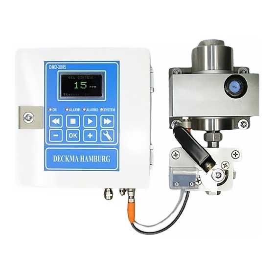
15ppm Bilge Alarm
Type OMD-2005
DECKMA HAMBURG GmbH
Kieler Straße 316, D-22525 Hamburg — Germany
Tel.: +49 (0) 40 54 88 76-0, Fax: +49 (0) 40 54 88 76-10
Internet: www.deckma.com
eMail: post@deckma.com
Related Manuals for Deckma Hamburg OMD-2005
Summary of Contents for Deckma Hamburg OMD-2005
-
Page 1
I N S T R U C T I O N M A N U A L 15ppm Bilge Alarm Type OMD-2005 DECKMA HAMBURG GmbH Kieler Straße 316, D-22525 Hamburg — Germany Tel.: +49 (0) 40 54 88 76-0, Fax: +49 (0) 40 54 88 76-10 Internet: www.deckma.com… -
Page 2
The purchaser shall bear the cost and risk of transport of defective parts and repaired parts supplied in replacement of such defective parts. ANY DISMANTLING OR BREAKING OF A SEAL WILL VOID THE WARRANTY Issue: 27.05.08 Instruction Manual OMD-2005 Page 2 of 25… -
Page 3: Table Of Contents
12.0 Operator Maintenance 12.1 Manual Cell Clean Unit 13.0 Fault Finding 13.1 Memory Card 14.0 Calibration 14.1 Calibration and Repeatability Check 15.0 Spare Parts 15.1 Recommended On Board Spares 16.0 Remarks Issue: 27.05.08 Instruction Manual OMD-2005 Page 3 of 25…
-
Page 4: Introduction
DECKMA HAMBURG GmbH INTRODUCTION The OMD-2005 Bilge Alarm Unit has been designed specifically for use in conjunction with 15 ppm oil-water separator units and has a specification and performance which exceeds the requirements of the International Maritime Organization specifications for 15ppm Bilge Alarms contained in Resolution MEPC.
-
Page 5: Principle Of Operation
In this mode also the individual adjustment of the time delays for the alarms and the possible changing between 0 — 20 mA or 4 — 20 mA output can be done. Issue: 27.05.08 Instruction Manual OMD-2005 Page 5 of 25…
-
Page 6
These contacts can be used for external processing of the signal or for control of further functions. If a malfunction or failure of the power supply occurs, all 3 relays will switch to alarm condition. Issue: 27.05.08 Instruction Manual OMD-2005 Page 6 of 25… -
Page 7: Specification
Roll: Up to 45° Size (over all): 360 mm W x 240 mm H x 100 mm D Degree of Protection: IP 65 Weight: 7,3 kg Pipe Connections: R ¼» Female Issue: 27.05.08 Instruction Manual OMD-2005 Page 7 of 25…
-
Page 8: Construction
DECKMA HAMBURG GmbH CONSTRUCTION There are 3 main parts which contained in an OMD-2005: The computer unit is mounted into an epoxy powder painted steel housing to protect the electronics of the display PCB with the data logger and the main board PCB with the terminals for external connections.
-
Page 9: Installation
20 s. Mount the OMD-2005 Monitor by means of 6 x M8 screws on to a rigid vertical surface and preferably with the display panel of the monitor at eye level. For service and maintenance sufficient space to all sides should be available.
-
Page 10: Piping
PIPING (Refer to Fig. 3) Connect the OMD-2005 Monitor to the sample point of the oily-water separator outlet and to a source of oil free water employing 10 mm OD copper or stainless steel pipe. The sample point should be located on a vertical section of the separator outflow piping to minimize the effects of any entrained air.
-
Page 11: Wiring
Do not use the pilot voltage for driving motors, heaters or other high load devices. The pilot voltage is intended for alarm purposes only. Issue: 27.05.08 Instruction Manual OMD-2005 Page 11 of 25…
-
Page 12
Solenoid Valve 3/2 Way Valve Automatic Stopping Device Air Supply Power Supply Fig. 5 Close front door complete after electrical installation. Water inside the instrument may result in corrosion and malfunction. Issue: 27.05.08 Instruction Manual OMD-2005 Page 12 of 25… -
Page 13: Typical Control System
Check the wiring of the automatic stopping device and to the alarm system is according the IMO Requirements. c) Check that the grounding has been made according to the relevant regulations. 10.2 Piping a) Check all piping connections for leaks and rectify as appropriate. Issue: 27.05.08 Instruction Manual OMD-2005 Page 13 of 25…
-
Page 14: Functional Tests
If this is the case, the cause must be located and rectified. f) If the Zero need to be adjusted, this can be done in the programming mode as described in section 10.4. (Service – Offset) Issue: 27.05.08 Instruction Manual OMD-2005 Page 14 of 25…
-
Page 15: Programming Mode
„+“ or „-„ output signal can be modified with “OK”. button. Press the „OK“ button. within the limitations. Select the required point by using the „+“ or „-„ button. Press the „OK“ button. Issue: 27.05.08 Instruction Manual OMD-2005 Page 15 of 25…
-
Page 16
Press the “Enter” button to >> Fast Forward show details >> and + Very Fast Forward 15 sec Backward — and + 2 min Backward << Fast Backward << and + Very Fast Backward Issue: 27.05.08 Instruction Manual OMD-2005 Page 16 of 25… -
Page 17: Operating Instructions
10.4 “Service — Offset”. d) Switch the instrument sample supply from the clean water supply to the separator sampling point connection. e) The instrument is now ready for use. Issue: 27.05.08 Instruction Manual OMD-2005 Page 17 of 25…
-
Page 18: Operator Notes
The protection cap of the spare unit can be also used as a tool. j) Reconnect the instrument to the separator sampling point. Issue: 27.05.08 Instruction Manual OMD-2005 Page 18 of 25…
-
Page 19: Manual Cell Clean Unit
NB: The Manual Cell Clean Unit may also be used during normal operation with sample water, but in this case an alarm occurs because the wiper is passing the light source. Spares: Wiper Seal, Part. No. 30605 Issue: 27.05.08 Instruction Manual OMD-2005 Page 19 of 25…
-
Page 20: Fault Finding
13.0 FAULT FINDING See Section 2 for important notes. The OMD-2005 will indicate several malfunctions in the status line of the display. Pressing the “OK” button will lead into an information window, similar to the items listed in the table below.
-
Page 21
DECKMA HAMBURG GmbH Important Information! Cleaning of Glass Tube at 15 ppm Bilge Alarms OMD-2005 IMPORTANT: NEVER DISASSEMBLE THE UNITS AS THIS MAY VOID THE CALIBRATION AND THE CERTIFICATION! CLEANING HAS ONLY TO BE DONE TROUGH THE REMOVED CELL CAP BY… -
Page 22: Memory Card
Under normal use the card should not be taken out, as this is linked with the specific system. The card can be read in other OMD-2005 units, but writing is only possible in the related system.
-
Page 23: Calibration
A function test for checking the correct installation, can easy be done by changing the position of the 3 way valve. At the clean water position the unit will be in alarm status. Issue: 27.05.08 Instruction Manual OMD-2005 Page 23 of 25…
-
Page 24: Spare Parts
2 off Desiccator 65550 1 off Cell Cleaning Brush 30102 1 off O-Ring Set 75775 2 off Fuse T 2 A 40107 Optional item 1 off Manual Cell Clean Unit 75780 Issue: 27.05.08 Instruction Manual OMD-2005 Page 24 of 25…
-
Page 25: Remarks
All the modifications and deviations from the standard form, which have to be carried out in the supply, should be attached at this paragraph. Commissioned on: ……by: ………. Date Firm’s Name Remarks: Issue: 27.05.08 Instruction Manual OMD-2005 Page 25 of 25…

INSTRUCTION MANUAL
15ppm Bilge Alarm
Type OMD-2005
DECKMA HAMBURG GmbHKieler Straße 316, D-22525 Hamburg — Germany
Tel.: +49 (0) 40 54 88 76-0, Fax: +49 (0) 40 54 88 76-10Internet: www.deckma.com eMail: [email protected]

DECKMA HAMBURG GmbH
Issue: 18.11.04 Instruction Manual OMD-2005 Page 2 of 24
IMPORTANT NOTICE
Replacement components for 15ppm Bilge Alarms.
General
All monitors in our range are inspected and tested to the related I.M.O. requirements atour factories prior to delivery.In normal use the units should operate correctly and without fault over a long period oftime requiring only small amounts of maintenance to be carried out as outlined in theinstruction manuals.
Service Exchange Units
In the event of a monitor malfunction due to electrical or electronic component failure itis our recommendation that a service exchange unit be ordered.The defective instrument should be returned to our works within 30 days of supplyingthe service exchange unit, then only the repair charge is payable. Otherwise the wholecost of a service exchange unit becomes payable.This procedure is by far the easiest and most cost effective way of ensuring the monitoron board conforms to I.M.O. resolution MEPC.107 (49).
Remark:
According the MEPC.107(49) § 4.2.11 the unit has to be checked at IOPP Certificaterenewal survey by the manufacturer or persons authorized by the manufacturer.Alternatively the unit may be replaced by a calibrated 15 ppm Bilge Alarm. The OMD-2005 is designed in that way, that only the measuring cell needs to be changed, as thisunit carry the calibration onboard. The Calibration Certificate with the date of the lastcalibration check should be retained onboard for inspection purposes.
If for some reasons the computer unit needs to be changed, it has to make sure, thatthe memory card will remain on board for at least 18 month. The new computer unit willcarry its own memory card. The old card can be insert into the new unit only for reading.Writing is only possible with the card delivered with the new computer unit. For detailssee section 13.1.

DECKMA HAMBURG GmbH
Issue: 18.11.04 Instruction Manual OMD-2005 Page 3 of 24
CONTENTS
SECTION TITLE PAGE
1.0 Introduction 42.0 Important Notes 43.0 Principle of Operation 43.1 Measuring Principle 43.2 Features 53.3 Adjustment 53.4 Displays and Alarms 54.0 Specification 75.0 Construction 86.0 Installation 97.0 Piping 108.0 Wiring 118.1 Typical Control System 139.0 Power Supply 13
10.0 Commissioning 1310.1 Electrical 1310.2 Piping 1310.3 Functional Tests 1410.4 Programming Mode 1511.0 Operating Instructions 1711.1 Operator Notes 1812.0 Operator Maintenance 1812.1 Manual Cell Clean Unit 1913.0 Fault Finding 2013.1 Memory Card 2114.0 Calibration 2214.1 Calibration and Repeatability Check 2215.0 Spare Parts 2315.1 Recommended On Board Spares 2316.0 Remarks 24

DECKMA HAMBURG GmbH
Issue: 18.11.04 Instruction Manual OMD-2005 Page 4 of 24
1.0 INTRODUCTION
The OMD-2005 Bilge Alarm Unit has been designed specifically for use inconjunction with 15 ppm oil-water separator units and has a specification andperformance which exceeds the requirements of the International MaritimeOrganization specifications for 15ppm Bilge Alarms contained in ResolutionMEPC. 107 (49).The unit is supplied with 2 works-adjusted alarms at 15 ppm. Other set points(10 ppm or 5 ppm) are possible and can be adjusted on site at any time by usingthe buttons at the front panel.If an alarm set point is exceed, the alarms are visible at the front panel and theappropriate relays are switched. In case of malfunction the System LED at thefront panel will change from blinking green to permanent red and the appropriaterelay will switch the contacts.For the data logging function the unit requires an status input from the separatorand a feedback signal from the valve position limit switch. (See Fig. 1, Pos.6)Furthermore a 0(4) — 20 mA (equal to 0 — 30 ppm) signal output is available fordriving a recorder or external meter.
2.0 IMPORTANT NOTES
a) This equipment must be installed and operated in strict accordance with theinstructions contained in this manual. Failure to do so will impair the protectionprovided.
b) Installation and servicing must be undertaken by a competent and suitableskilled person.
c) The equipment must be connected to the ground according relevantrequirements.
d) The unit must be isolated from the electrical supply before any maintenance ofthe equipment is attempted.
e) All National or local codes of practice or regulations must be observed and,where applicable, are deemed to take precedence over any directive orinformation contained in this manual.
f) In case of freezing conditions the measuring cell should be emptied complete.

DECKMA HAMBURG GmbH
Issue: 18.11.04 Instruction Manual OMD-2005 Page 5 of 24
3.0 PRINCIPLE OF OPERATION
3.1 Measuring PrincipleAn optical sensor array measure a combination of light scattered and absorbedby oil droplets in the sample stream. The sensor signals are then processed by amicroprocessor to produce linearised output.If an alarm (works set point 15 ppm) occurs, the two oil alarm relays are activatedafter the adjusted time delay.The microprocessor continuously monitors the condition of the sensorcomponents and associated electronics to ensure that calibration accuracy ismaintained over time and extremes of environmental conditions.
3.2 Features• Robust construction• Automatic voltage selection• Solid suppression capability• Low maintenance• Easy installation• Constant readiness• Low spare part stock holding• Watertight Housing• Works adjustment• Easy settings via menu
3.3 AdjustmentThe unit is delivered with a works calibration according the IMO-requirements.The alarm points are set to 15 ppm.The «Zero» point is also works calibrated and can be re-adjusted on site by usingthe programming mode and clean water. See Section 10.4 “Service-Offset”. Acalibration is not permitted. This has to be done according IMO Regulations bythe manufacturer or persons authorized by the manufacturer.
3.4 Displays and AlarmsIn the unit are two independent oil alarm circuits available. Both can be setseparately from 1 to 15 ppm. From the manufacturing both alarms are set to15 ppm (according IMO). The set points can be changed according to therequirements on site, for example to 10 ppm or 5 ppm. An alarm point settingabove 15 ppm is not possible. The adjustment can be done in the programmingmode as described in Section 10.4.In this mode also the individual adjustment of the time delays for the alarms andthe possible changing between 0 — 20 mA or 4 — 20 mA output can be done.

DECKMA HAMBURG GmbH
Issue: 18.11.04 Instruction Manual OMD-2005 Page 6 of 24
Both alarm circuits are also related to an alarm LED on the front panel.In case of malfunction the “System” LED will indicate any type of internal fault ofthe unit. This LED is flashing green in normal conditions and is red in alarmconditions. Also this alarm is related to an relay output.Additional to the alarm LED’s each alarm circuit is equipped with a relay withpotential free alarm contacts. These contacts can be used for external processingof the signal or for control of further functions.If a malfunction or failure of the power supply occurs, all 3 relays will switch toalarm condition.

DECKMA HAMBURG GmbH
Issue: 18.11.04 Instruction Manual OMD-2005 Page 7 of 24
4.0 SPECIFICATION OMD-2005
Range: 0 – 30 ppm, Trend up to 50 ppm
Accuracy According IMO MEPC. 107(49)
Linearity Up to 30 ppm better than ± 2 %
Display Green Graphic Display
Power Supply: 24 V – 240 V AC or DCAutomatic Voltage Selection
Consumption: < 15 VA
Alarm Points 1 + 2: Adjustable between 1 — 15 ppm(Works adjustment 15 ppm)
Alarm 1 Operating Delay:(for annunciation purpose)
Adjustable between 1 – 540 sec.(Works adjustment 2 sec)
Alarm 2 Operating Delay:(for control purposes)
Adjustable between 1 – 10 sec.(Works adjustment 10 sec)
System Fault Alarm: Red LED
Alarm Contact Rating: Potential free 1 pole change overcontacts, 3 A / 240 V
Alarm Indication: Red LED’s
Output Signal: 0 – 20 mA or 4 – 20 mA for 0-30 ppmreversible, ext. Load < 150 Ω
Sample Water Pressure: 0,1 – 10 bar
Sample Flow: Approx. 0,1 — 4 l/min depend. to pressure
Ambient Temperature: + 1 to + 55° C
Sample Water Temperature: + 1 to + 65° C
Roll: Up to 45°
Size (over all): 360 mm W x 240 mm H x 100 mm D
Degree of Protection: IP 65
Weight: 7,3 kg
Pipe Connections: R ¼» Female

DECKMA HAMBURG GmbH
Issue: 18.11.04 Instruction Manual OMD-2005 Page 8 of 24
5.0 CONSTRUCTION
There are 3 main parts which contained in an OMD-2005:The computer unit is mounted into an epoxy powder painted steel housingto protect the electronics of the display PCB with the data logger and themain board PCB with the terminals for external connections.The measuring cell is built out of an anodized all-aluminium body with inletand outlet block in stainless steel. This rugged cell contains the opticalelectronic and correspond with the computer unit via a plugged data cable.The valve assembly contains a special handle to sense the position of thevalve. This assembly is connected to the measuring cell by an easy tohandle fitting to enable the exchange of the cell for frequently adjustmentaccording the IMO requirements.
All components are mounted to a stainless steel mounting plate for easy wall orbulkhead installation. It is also possible to split the computer unit from themeasuring cell if the available space is not sufficient. For this version dividedmounting plates are available.
ON
OMD-2005Oil Monitoring Device
Alarm 1 Alarm 2 System
OK
DECKMA HAMBURGwww.deckma.com
S A M P L E 1 / 4 «
C L E A N W A T E R 1 / 4 «
O U T 1 / 4 «
D E C K M A H A M B U R GD H 7 5 4 5 0
1 Computer Unit 5 Handle 9 3/2 Way Valve2 Head Screw 6 Limit Switch 10 Mounting Plate3 Fitting 7 Spacer 11 Desiccator4 Measuring Cell 8 Valve Plate 12 Communication Cable
Fig. 1

DECKMA HAMBURG GmbH
Issue: 18.11.04 Instruction Manual OMD-2005 Page 9 of 24
6.0 INSTALLATION (Refer to Fig. 2 and Fig. 3)
See Section 2 for important notes concerning installation.The OMD-2005 Monitor should be located as close as possible to the oily waterseparator to minimize response delays. According MEPC.107(49) the layout ofthe installation should be arranged so that the overall response time (includingthe response time of the 15 ppm Bilge Alarm) between an effluent discharge fromthe 15 ppm Bilge Separator exceeding 15 ppm, and the operation of theAutomatic Stopping Device preventing overboard discharge, should be as shortas possible and in any case not more than 20 s.Mount the OMD-2005 Monitor by means of 6 x M8 screws on to a rigid verticalsurface and preferably with the display panel of the monitor at eye level. Forservice and maintenance sufficient space to all sides should be available.Care must be taken at mounting of the pipes connections to avoid any torsion ofthe housing and damage of the instrument.
ON
OMD-2005Oil Monitoring Device
Alarm 1 Alarm 2 System
OK
DECKMA HAMBURGwww.deckma.com
S A M P L E 1 / 4 «
C L E A N W A T E R 1 / 4 «
O U T 1 / 4 «
D E C K M A H A M B U R GD H 7 5 4 5 0
Fig. 2

DECKMA HAMBURG GmbH
Issue: 18.11.04 Instruction Manual OMD-2005 Page 10 of 24
7.0 PIPING (Refer to Fig. 3)
Connect the OMD-2005 Monitor to the sample point of the oily-water separatoroutlet and to a source of oil free water employing 10 mm OD copper or stainlesssteel pipe. The sample point should be located on a vertical section of theseparator outflow piping to minimize the effects of any entrained air. The tappingpoint should be at a level above the outlet of the monitor to ensure the samplecell is flooded at all times.If connection to a vertical section of the separator outlet piping is impractical, thetapping may be made into the side of the horizontal pipe. Avoid top or bottomentry.For separator discharge pipes up to 75 mm OD a standard «T»-type junction ofthe welded or screwed type is satisfactory for the tapping point. For the separatordischarge pipes of 80 mm OD and above a sample probe should be employedwhich protrudes into the discharge piping by approx. 25 % of the ID of the pipe.
Separator
Outlet Separator
Clean WaterSupply (Option)
Outlet *
10 X 1mmCopper Tube
Vacuum breaker
Overboard discharge
Pressure relief valve(if required)
To Bilge
* Inlet & Outlet connections R1/4″ FemaleFig. 3
To BilgeTo Bilge
RecirculatingFacilities
AutomaticStopping Device
ON
OMD-2005Oil Monitoring Device
Alarm 1 Alarm 2 System
OK
DECKMA HAMBURGwww.deckma.com
DE C KM A H AM B UR GDH 7 5 4 50

DECKMA HAMBURG GmbH
Issue: 18.11.04 Instruction Manual OMD-2005 Page 11 of 24
8.0 WIRING (Refer to Fig. 4 + 5)
See Section 2 for important notes concerning wiring.This unit must be connected to the mains supply via a suitable rated andapproved fused isolator unless such fusing / isolation is provided by associatedequipment. When fitted, the isolator should be close, readily accessible andmarked as to function.Electrical connections are made through the metric cable gland openingsprepared underneath the instrument.
Fig. 4
Precise wiring details will vary dependent upon the control system to beemployed but the most frequently used systems employ alarm relay 1 for alarmonly and alarm relay 2 for control purposes.Electrical connections are made to the terminal blocks inside the computerhousing. Wires are connected to the terminals by pushing a suitable screwdriverinto the clamp holes to release the internal spring loaded clamps. After the wire isinserted to the terminal and the screwdriver is removed, the wire is fixed.If the instrument is operated at high voltages, additional care has to be taken toprovide reliable ground connections. Ground (PE) can be connected direct to theterminal or, if this is not sufficient according local rules, to the computer housingleft side. In this case the plug needs to be replaced by a M6 screw with nut andrelated washers.The instrument provides a pilot voltage output at terminals 4&5. This is internallyconnected to the power supply input (Terminals 1&2), but is fused by Fuse F1 (2A). The pilot voltage can be used to supply additional external circuitry, e.g. alarmlamps or electrical valves.Please note: any device connected to the pilot voltage output must be rated forthe voltage the instrument is supplied with. Do not use the pilot voltage for drivingmotors, heaters or other high load devices. The pilot voltage is intended for alarmpurposes only.

DECKMA HAMBURG GmbH
Issue: 18.11.04 Instruction Manual OMD-2005 Page 12 of 24
Signal Output0(4)-20 mA
To Alarmsystem
3/2 Way ValveAutomatic Stopping Device
Power Supply Air Supply
Solenoid Valve
1 2 3
19 20 21 22 23 24 25 26 27 28 29 30 31 32 33 MeasuringCell
Logger /Display
F2F1Res.PILOT V
24-240V INFLOW STATUS RES OUTPUT CLEAN
PE PE PE + — PE PE
L N PE4 5 6
PILOT OUTL N PE
7 8 9A B PE
RES13 14 15NO COM NC
ALARM 216 17 18NO COM NC
10 11 12NO COM NC
ALARM 1 SYSTEM FAULT
1A2A
Contacts shownin Alarm condition(de-energised)
StatusSeparator
LimitSwitch
To Alarmsystem(optional)
1-2 Power Supply4-5 Pilot Voltage Output (Same as Power Supply)7-8 Spare Voltage Output (Same as Power Supply)10-12 Potential free Output Alarm 1 (Change over contact)13-15 Potential free Output Alarm 2 (Change over contact)16-18 Potential free Output System Fault (Change over contact)19-20 Input Flow Direction Switch (Deckma Delivery)22-23 Input Status Switch from Separator (Close when running)25-26 Input Spare Switch28-29 Signal Output 0(4) to 20 mA31-32 Optional Output for Autoclean Valve
EXAMPLEConnections may varywith different separatorcontrol boxes
Fig. 5
Close front door complete after electrical installation. Water inside the instrumentmay result in corrosion and malfunction.

DECKMA HAMBURG GmbH
Issue: 18.11.04 Instruction Manual OMD-2005 Page 13 of 24
8.1 Typical Control SystemThe installation on site has to make sure that in case of any loss of power supplyand/or loss of air supply for the automatic stopping device the overboarddischarge valve close the overboard line and open the re-circulating line.The system showed in the example, employs alarm relay 2 to control apneumatic solenoid valve which energises or de-energises a pneumaticallyoperated 3 — way valve as depicted in Fig. 5.The separation process will continue until such time as the pollution level fallsbelow the alarm set point at which time the discharge will be directed overboard.A pump stop system is according MEPC.107 (49) not allowed.
9.0 POWER SUPPLY
See Section 2 for important notes.The unit is designed for a power supply of 24 V to 240 V AC or DC. It has anautomatic power selection.
10.0 COMMISSIONING
See Section 2 for important notes.On completion of the installation, wiring and piping carry out the following checks:
10.1 Electricala) Check that the power supply is connected to the terminals 1 + 2 of the
terminal block.b) Check the wiring of the automatic stopping device and to the alarm system is
according the IMO Requirements.c) Check that the grounding has been made according to the relevant
regulations.
10.2 Pipinga) Check all piping connections for leaks and rectify as appropriate.

DECKMA HAMBURG GmbH
Issue: 18.11.04 Instruction Manual OMD-2005 Page 14 of 24
10.3 Functional Testsa) Run oil free water through the instrument to purge the system.b) Adjust the flow rate through the unit by using the small screws in the cell cap
(Fig. 1, Pos. 2). Taking out a screw will increase the flow rate.NB: The flow rate should be checked on both, the clean water supply and theseparator sample supply. If the clean water supply is obtained from a highpressure source, the flow rate will be higher than from the sample point.The flow rate is not influencing the accuracy of the instrument. The adjustmentis only important for the time delay between the sample point and the monitor.
c) Switch on the instrument and make sure, that the Power LED is illuminatedand the display is showing theinitializing display for about 15sec. After that time it willchange to the standard display,showing the actualmeasurement.
d) During oil free water is running through the monitor check the Zero adjustmentaccording Section 11. The display should be «0» to “2” and the status will show“FW”. If the display varies by greater amounts, it may be that air entrainment ispresent. If this is the case, the cause must be located and rectified.
f) If the Zero need to be adjusted, this can be done in the programming mode asdescribed in section 10.4. (Service – Offset)

DECKMA HAMBURG GmbH
Issue: 18.11.04 Instruction Manual OMD-2005 Page 15 of 24
10.4 Programming ModeIn the programming mode the alarm set points, the time delays, the signal outputand the zero can be modified. It is also possible to recall the factory default
values at any time. The clock isfactory set for GMT, Greenwich MeanTime, and cannot be changed.There are 8 push buttons to controlthe functions of the display. In generalare the upper buttons for the datalogger and the lower buttons forchanging the display to the differentpages of the menu.
Pressing the OK button will givemore detailed information aboutthe status
After start the display will showthe initial display followed bythe actual measured oil content.This display also be shown, ifno input at the different menu’shas been done for a designatedtime
To get into the menu press thetool button. Select the requiredpoint by using the „+“ or „-„button. Press the „OK“ button.
At the service menu the alarms,time delays, the Offset and theoutput signal can be modifiedwithin the limitations. Select therequired point by using the „+“or „-„ button. Press the „OK“button.
To change the value, pressthe “+” or “-“ button. Confirmwith “OK”.
OK
Doub le Ar row back
EnterArro
w fo rward
Doub le Ar row forward
» — «But ton
«OK» Bu t ton
«+» Bu t ton
Too l Bu t ton

DECKMA HAMBURG GmbH
Issue: 18.11.04 Instruction Manual OMD-2005 Page 16 of 24
Select the required point byusing the „+“ or „-„ button.Press the „OK“ button.
To change the value, pressthe “+” or “-“ button. Confirmwith “OK”.
Select the required point byusing the „+“ or „-„ button.Press the „OK“ button.
To change the value, pressthe “+” or “-“ button. Confirmwith “OK”.
To get into the menu press thetool button. Select the requiredpoint by using the „+“ or „-„button. Press the „OK“ button.
The display will show the actualstatus of the data logger. To getback to the standard displaypress the tool button or the OKbutton.
Function of the scrolling buttonsfor both operation time historydisplays:
> 15 sec Forward
> and + 2 min Forward
>> Fast Forward
>> and + Very Fast Forward
— 15 sec Backward
— and + 2 min Backward
<< Fast Backward
<< and + Very Fast Backward
Press the “Enter” button to getinto the history. Select therequired date and time by usingthe buttons.The dotted vertical line showsthe actual position.
Press the “Enter” button toshow details
The detailed information ofthe selected date and timewill be displayed. To getback to the history graph,press the “Enter” Buttonagain. To get back to thestart display, press the “OK”button.

DECKMA HAMBURG GmbH
Issue: 18.11.04 Instruction Manual OMD-2005 Page 17 of 24
To get into the menu press thetool button. Select the requiredpoint by using the „+“ or „-„button. Press the „OK“ button.
The temperature of themeasuring cell and the samplewater will be shown
To get into the menu press thetool button. Select the requiredpoint by using the „+“ or „-„button. Press the „OK“ button.
The details of the measuringcell will be shown.
To get into the menu press thetool button. Select the requiredpoint by using the „+“ or „-„button. Press the „OK“ button.
Information about the softwareversion and the web addresswill be shown.
NB: All changed values have to be confirmed by pressing the » OK » button.Otherwise the existing values are valid.
11.0 OPERATING INSTRUCTIONS
a) Switch on the power supply.b) Allow a period of time for water entering the sample tube.c) Flow oil free water through the system for a few minutes and check that the
display show 0 to 2 ppm. If not, clean proper before adjusting the unitaccording section 10.4 “Service — Offset”.
d) Switch the instrument sample supply from the clean water supply to theseparator sampling point connection.
e) The instrument is now ready for use.

DECKMA HAMBURG GmbH
Issue: 18.11.04 Instruction Manual OMD-2005 Page 18 of 24
11.1 Operator Notesa) When oily water flows through the instrument the display will show the actual
value of oil content.b) If the oil concentration exceeds the adjusted threshold (works adjustment
15 ppm), the alarm indicator 1 will be illuminated in intervals during theselected time delay before it change to steady light and the associated alarmrelay will operate. Accordingly also the alarm indicator 2 will be illuminatedand its associated alarm relay will take the appropriate shut down action.
12.0 OPERATOR MAINTENANCE
See Section 2 for important notes.AT WEEKLY INTERVALS:a) Flush the cell with oil free water.b) Isolate the instrument from both, sample and oil free water supply.c) Unscrew and remove the cell cap.d) Insert a suitable Cell Cleaning brush (Art. No. 30102) into the cell and clean it
with upwards and downwards motion through the entire length of the cellseveral times.
e) Remove the Cell Cleaning brush and replace the cell cap.f) Reconnect the oil free water supply and allow this to flow through the
instrument for a few minutes.g) Observe that the display is showing «0» to “2”. If not, clean again.h) Examine the color of the desiccator (Fig. 1, Pos. 11). Blue color is indicating
an active moisture absorber. If the color is light blue or white, the desiccatorshould be replaced.The desiccator assures a humidity below 40% inside the measuring cell toavoid wrong measurement resulting due to condensation at the cell glass tubeand damage of the electronics around the glass tube. The replacement is easydone without opening the instrument. Just unscrew the old desiccator out ofthe front panel and replace it by a new one. The protection cap of the spareunit can be also used as a tool.
j) Reconnect the instrument to the separator sampling point.

DECKMA HAMBURG GmbH
Issue: 18.11.04 Instruction Manual OMD-2005 Page 19 of 24
12.1 Manual Cell Clean UnitOptional item if fittedThis unit facilitates cleaning of the cell without the need of removing the cell cap.Regular use of this device should prevent malfunction of the monitor due simplyto fouling of the sample tube and all the inconvenience which this can cause.Operating Instructionsa) Ensure that the monitor is switched off and that there is a clean water supply
through the cell.b) Activate the manual cell clean unit by pressing the handle several times.c) Switch the monitor back on and check the reading is between 0 to 2 ppm.d) Repeat a) to c) at least once a week or as necessary.NB: The Manual Cell Clean Unit may also be used during normal operation withsample water, but in this case an alarm occurs because the wiper is passing thelight source.Spares: Wiper Seal, Part. No. 30605

DECKMA HAMBURG GmbH
Issue: 18.11.04 Instruction Manual OMD-2005 Page 20 of 24
13.0 FAULT FINDING
See Section 2 for important notes.
The OMD-2005 will indicate several malfunctions in the status line of the display.Pressing the “OK” button will lead into an information window, similar to the itemslisted in the table below.
Status Reading System-Alarm-circuit
Alarm-circuit 1,2
Reason Servicing
LED Alarm
OK 0..49 Green /Blinking
No Normaloperation
Normal operation —
OK EE Green /Blinking
No Alarm Sample reading is outof range:Oil content too high,dirty sample tube
Wait until oil content iswithin the range,clean sample tube
FW ! 0..49 / EE Green /Blinking
No Alarm Freshwater is enabled —
Sample? EE Red /Steady
Yes Alarm Meter is not able tomeasure the sample:no water in, oil contentmuch too high, no lighttransmission possible
Check sample, cleansample tube
Com? EE Red /Steady
Yes Alarm No communicationbetween computer unitand measuring cell
Check connectionbetween computerunit and measuringcell
Datalogging is notpossible:no DECKMA card in
Insert the activememory card
Datalogging is notpossible:a read only card is in
Insert the activememory card
Datalog? 0..49 / EE Red /Steady
Yes Alarm
Datalogging is notpossible:a new DECKMA card isin
Activate card or insertthe active memorycard
Int.Err Red /Steady
Yes Alarm Internal error Restart the system

DECKMA HAMBURG GmbH
Issue: 18.11.04 Instruction Manual OMD-2005 Page 21 of 24
1 2 3
19 20 21 22 23 24 25 26 27 28 29 30 31 32 33 MeasuringCell
Logger /Display
F2F1PILOT VOLT.POWER
24-240V INFLOW STATUS RES OUTPUT CLEAN
PE PE PE + — PE PE
L N PE4 5 6
PILOT OUTL N PE
7 8 9A B PE
RES13 14 15NO COM NC
ALARM 216 17 18NO COM NC
10 11 12NO COM NC
ALARM 1 SYSTEM FAULT
Pro tec t ion CoverD isp lay PCBTerm ina ls Ma in PCB wi th Ho lder Computerhous ing
D isp lay PCBMemoryCard
Sta tus LED ‘s :D7 Power OND11 Mic roprocessor (b l ink ing)D12 Measur ing Ce l l (b l ink ing)D13 Disp lay (b l ink i ng)D14 Spare
D19 Ala rm 1 OFFD20 Ala rm 2 OFFD21 Sys tem Fau l t OFF
D22 Spare
D15 Sta tus Separa to rD16 Sta tus Water Supp l yD17 SpareD18 Sta tus Data logge r
D23 A larm 1 OND24 Alarm 2 OND25 Sys tem Fau l t ON
D26 Spare
Fig. 6
13.1 Memory Card (refer to Fig. 6)The Memory Card is located inside the door of the computer housing. It issuitable for the life of the instrument, as it is calculated to the according MEPC107(49) required storage time of at least 18 month. When the card is full, theoldest entry will be overwritten, so that a replacement is not necessary. Undernormal use the card should not be taken out, as this is linked with the specificsystem. The card can be read in other OMD-2005 units, but writing is onlypossible in the related system.

DECKMA HAMBURG GmbH
Issue: 18.11.04 Instruction Manual OMD-2005 Page 22 of 24
14.0 CALIBRATION
15 ppm Bilge Alarms built according MEPC.107(49) have to be protected againstaccess beyond the checks of instrument drift, repeatability of the instrumentreading and zero adjustment. For this reason the instrument is electronicallysealed, so that only the manufacturer or his authorized persons, equipped withthe related tools, are able to get access for changing the calibration.To provide a simple procedure for check the instrument aboard ship, the OMD-2005 is constructed in that way, that the zero check also confirms the instrumentdrift within the specifications.
14.1 Calibration and repeatability checka) Switch off the power supply and stop any water flow.e) Clean the sample tube accurate by using a suitable cell cleaning brush as
described under Section 12.0. Make sure, that the offset is correct at ± 0.f) Run clean water through the instrument.g) If it is sure, that non aerated, clean water is in the instrument, the reading
should be 0 ppm ± 2 ppm.a) Continue as described under Section 11.0.

DECKMA HAMBURG GmbH
Issue: 18.11.04 Instruction Manual OMD-2005 Page 23 of 24
15.0 SPARE PARTS
When ordering spares, it is important to supply details of the type of monitor, partnumber of each spare required, its description and any relevant serial number.
DESCRIPTION ART-NUMBER
Desiccator 65550
Cell Cleaning Brush 30102
O-Ring Set 75775
Fuse, T 2 A 40107
Fuse, T 1 A 40105
Measuring Cell with Calibration Certificate 75500/17300
15.1 Recommended On Board Spares
2 off Desiccator 65550
1 off Cell Cleaning Brush 30102
1 off O-Ring Set 75775
2 off Fuse T 2 A 40107
Optional item
1 off Manual Cell Clean Unit 75780

DECKMA HAMBURG GmbH
Issue: 18.11.04 Instruction Manual OMD-2005 Page 24 of 24
16.0 REMARKS
All the modifications and deviations from the standard form, which have to becarried out in the supply, should be attached at this paragraph.
Commissioned on: ……………………….. by: …………………………………… Date Firm’s Name
Remarks:


Name and address of lhemanufacturer:
Date of issue:
Annex 4.1 ltem No &Item designation
EG-Type Examination
Certificate-No.
DECKMA Hamburg GmbH,
27.03.2006
A.1/2.3 — Oil-content meters
(Module B)
320,028
See-BerufsgenossenschaftPrüf- und ZertifizierungsstelleiM BG-PRÜFZERT
European notified bodyldentification number 0736
Certificate
Kieler Straße 316,22525 Hamburg, Germany
Product designation:
Product Type:
Intended purpose:
Oil-in-water monitor
oMD — 2005
Oil content meter (1S-ppm alarm) for oily water separating equipment onsea going vessels acc. MARPOL 73fl8, Annex I
Testing based on(Specific standard);
Remarks:
IMO Resolution MEPC.1 07(49) for oil content meters and oily waterseparating equipment in acc. with MARPOL 73178, Annex I, Reg. 16
The type tested was found to be in compliance wjth the lvlarine-pollution prevention requirements of l4arine Equipment Directive(MED) 96/98/EC as amended by Diective 2OO2l7 s/EC subject to any conditions in the schedule (part of this certificate).
This certificate mav onlv be used in connection with module(s) D Of F Of E of this directive.
30.09.2009Expirydate: I
go.og.zoog |
/o /,rlSignature 16eifert)The approval of the installed equipment will be in force beyond the validity date until it is revoked!
Note 1 : This certificate will not be valid if the manufacturer makes any changes or modifications to the approvedwhich have not been notified to, and agreed with the notified body named on this certificate.
Note 2: Should the specjfied regulations or standards be amended during the validity of this certif icate, the product(s) is/are to beto ivthev beinq placed on board vessels to which the amended requlations or standards apply.
Note 3: The Mark of Conformity may only be affixed to the above type approved equipment and a l4anufacturer’s Declaration ofConformity issued when the production-control phase module (D, E, or F) ofANNEX B ofthe Directive is fully complied with andcontrolled bv a written i reement with a notified
Note 4: «Wheelmark» Format» lrsl two digits ofyear märk affied.
XXXX Notified Body number undertaking surveillance modulexx$/yy
Postaladdress:Postfach 11 04 8920404 Hamburg
Office:Reimerstwiete 220457 Hamburg
lel: 0 40/3 61 37-0Fax: O 4Ol3 61 37 204In any case, theGeman original shall preEil.


DECKMA HAMBURG GmbH
IMPORTANT NOTICE
Replacement components for 15ppm Bilge Alarms.
General
All monitors in our range are inspected and tested to the related I.M.O. requirements at
our factories prior to delivery.
In normal use the units should operate correctly and without fault over a long period of
time requiring only small amounts of maintenance to be carried out as outlined in the
instruction manuals.
Service Exchange Units
In the event of a monitor malfunction due to electrical or electronic component failure it
is our recommendation that a service exchange unit be ordered.
The defective instrument should be returned to our works within 30 days of supplying
the service exchange unit, then only the repair charge is payable. Otherwise the whole
cost of a service exchange unit becomes payable.
This procedure is by far the easiest and most cost effective way of ensuring the monitor
on board conforms to I.M.O. resolution MEPC.107 (49).
Remark:
According the MEPC.107(49) § 4.2.11 the unit has to be checked at IOPP Certificate
renewal survey by the manufacturer or persons authorized by the manufacturer.
Alternatively the unit may be replaced by a calibrated 15 ppm Bilge Alarm. The OMD-
2005 is designed in that way, that only the measuring cell needs to be changed, as this
unit carry the calibration onboard. The Calibration Certificate with the date of the last
calibration check should be retained onboard for inspection purposes.
If for some reasons the computer unit needs to be changed, it has to make sure, that
the memory card will remain on board for at least 18 month. The new computer unit will
carry its own memory card. The old card can be insert into the new unit only for reading.
Writing is only possible with the card delivered with the new computer unit. For details
see section 13.1.
Warranty
Our warranty terms are12 months after installation but maximal 18 months after delivery
ex works. The maker undertakes to remedy any defect resulting from faulty materials of
workmanship except wearing parts.
The maker’s obligation is limited to the repairs or replacement of such defective parts by
his own plant or one of his authorized service stations.
The purchaser shall bear the cost and risk of transport of defective parts and repaired
parts supplied in replacement of such defective parts.
ANY DISMANTLING OR BREAKING OF A SEAL WILL VOID THE WARRANTY
Issue: 27.05.08
Instruction Manual OMD-2005
Page 2 of 25

АКРОС
ИНЖИНИРИНГОВАЯ
КОМПАНИЯ
Калибровка сигнализатора DECKMA OMD (15ppm) MEPC.107(49)
Модель: OMD-2005/OMD-2008(EV)/OMD-24
Производитель : DECKMA Hamburg GmbH
Резолюция: IMO MEPC.107(49), IMO MEPC.285(70)
Период действия калибровочного сертификата: 5 лет
Вид калибровки: на борту судна / на испытательном стенде
Внимание!
Калибровка сигнализатора в несколько раз выгодней, чем его замена. Специалисты нашей компании имеют сертификацию производителя на данный вид работ и проводят калибровку устройств по всему миру. В случае необходимости срочный калибровки вы всегда можете отправить сигнализатор в наш адрес транспортной компанией и получить его назад со всеми необходимыми бумагами.
Заказать калибровку сигнализатора DECKMA OMD 24/ 2005/ 2008
Согласно инструкции производителя, калибровка сигнализаторов Deckma OMD-24, OMD-2005, OMD-2008 должна проводиться не реже, чем раз в 5 лет. Аналогичные требования к калибровке трюмных сигнализаторов 15ppm предъявляются резолюциями IMO MEPC.107(49), MEPC.285(70) и прочими конвенциями.
Калибровочные работы по сигнализаторам нефтесодержания на 15ppm DECKMA проводятся исключительно сервисным инженером, имеющим свидетельство на проведение данного вида работ.
Калибровка сигнализатора проводится на борту судна специалистом Группы компаний АКРОС и включает следующие процедуры:
- Проверка документации и заводских пломб сигнализатора;
- Проверка настроек сигнализатора 15ppm;
- Промывка оптики сигнализатора на 15ppm;
- Проверка состояния резервного источника питания и его замена в случае необходимости;
- Проверка карты памяти устройства в соответствии с IMO MEPC.107(49);
- Проверка подачи сигнала на УАПС;
- Калибровка сенсора измерительной ячейки с использованием заводских средств и жидкостей;
- Замена расходных элементов оборудования.
- Оформление калибровочного сертификата на 5 лет.
Внимание!
Не пытайтесь самостоятельно заменить элемент питания (батарея) или чипы устройства! Данное вмешательство может повлечь за собой сбой в параметрах устройства, а также полную блокировку сигнализаторов DECKMA OMD series.
Не извлекайте карту памяти устройства!
Любое нарушение пломб влечет за собой аннулирование калибровочного сертификата.
Группа компаний АКРОС является официальным представителем компании DECKMA GmbH.
В дополнение к этому, инженеры компании проходят обучение у производителя оборудования.
Заказать калибровку сигнализатора 15ppm
DECKMA OMD-24/ OMD-2005/ OMD-2008
Заполните форму ниже, наш инженер подберет решения для Вашего судна, а также предоставит информацию о стоимости
Поддержка клиентов (Россия):
+7(984)-188-97-38
Поддержка клиентов (Ю. Корея):
+82 (10) 5377 6370
Заказать калибровку других сигнализаторов на 15ppm
©Группа компаний
«АКРОС«
Все права защищены.
Контакты:
690089, г. Владивосток,
ул. Тухачевского, 56/80
Тел: +7-(984)-188-97-38
E-mail: office@acroseng.ru
![]()

BEDIENUNGSANLEITUNG
15 ppm Bilge Alarm
Typ OMD-2005
DECKMA HAMBURG GmbH
Kieler Straße 316, D-22525 Hamburg - Germany
Tel.: +49 (0) 40 54 88 76-0, Fax: +49 (0) 40 54 88 76-10
Internet: www.deckma.com
eMail: [email protected]
DECKMA HAMBURG GmbH
Wichtiger Hinweis
Austausch von Elektronik Komponenten bei Geräten der OMD Typenreihe
Allgemeines
Unsere Geräte werden werksseitig einer strengen Qualitätskontrolle unterzogen und
sind gemäß den IMO-Vorschriften abgeglichen.
Unter normalen Betriebsbedingungen und unter Beachtung der in den Betriebsanleitungen gegebenen Wartungshinweisen werden die Geräte über einen längeren
Zeitraum ohne Ausfall arbeiten.
Austauschgeräte - Service
Falls es trotz der vorgenannten Sorgfalt zu einem Ausfall des Gerätes kommt,
empfehlen wir Ihnen ein Service-Austauschgerät bei uns zu bestellen.
Unter der Voraussetzung, das Sie uns das defekte Gerät innerhalb einer
angemessenen Frist (30 Tage) zurücksenden, sind lediglich die Kosten für ein
Austauschgerät zahlbar. Andernfalls ist die volle Summe eines Neugeräts, wie in der
mit dem Austauschgerät an Sie versandten Rechnung genannt, voll zahlbar.
Wie die Praxis gezeigt hat, ist dieses der für den Betreiber kostenmäßig günstigste Weg
und stellt gleichzeitig sicher, das ein den IMO-Vorschriften gemäßes Gerät eingesetzt
ist.
Anmerkung:
Gemäss den MEPC.107(49) § 4.2.11 Vorschriften muss die Einheit bei Erneuerung des
IOPP Zertifikats durch den Hersteller oder einer vom Hersteller autorisierten Person
überprüft werden. Alternativ kann die Einheit durch ein kalibriertes Gerät ersetzt
werden. Der OMD-2005 ist so konstruiert, das nur die Messzelle ausgewechselt werden
muss, da nur dieses Teil die für die Kalibrierung relevant ist. Das Zertifikat mit dem
Datum der letzten Kalibrierung muss an Bord aufbewahrt werden um den jeweiligen
Behörden vorgelegt werden zu können.
Wenn aus irgendwelchen Gründen auch die Computereinheit gewechselt werden soll,
muss sichergestellt sein, dass die Speicherkarte für mindestens 18 Monate an Bord
verbleibt. Die neue Computereinheit ist mit einer eigenen Speicherkarte ausgerüstet.
Die alte Karte kann in der neuen Einheit nur gelesen werden, Speicherung von Daten
erfolgt nur auf der neu gelieferten Karte.
Weitere Einzelheiten siehe Abschnitt 13.1.
Issue: 05.07.05
Bedienungsanleitung OMD-2005
Seite 2 of 24
DECKMA HAMBURG GmbH
Inhalt
ABSCHNITT
Issue: 05.07.05
TITEL
SEITE
1.0
Einführung
4
2.0
Wichtige Hinweise
4
3.0
Gerätebeschreibung
4
3.1
Messprinzip
4
3.2
Merkmale
5
3.3
Justierung
5
3.4
Anzeigen und Alarme
5
4.0
Technische Daten
7
5.0
Aufbau
8
6.0
Installation
9
7.0
Rohranschlüsse
10
8.0
Elektrische Anschlüsse
11
8.1
Typische Steuerung
13
9.0
Spannungsversorgung
13
10.0
Inbetriebnahme
13
10.1
Elektrisch
13
10.2
Rohranschlüsse
13
10.3
Funktionstest
14
10.4
Programmiermodus
15
11.0
Betriebsanweisungen
17
11.1
Benutzerhinweise
18
12.0
Wartung
18
12.1
Manuelle Zellenreinigung
19
13.0
Fehlersuche
20
13.1
Speicherkarte
21
14.0
Kalibrierung
22
14.1
Kalibrierung und Wiederholbarkeitsprüfung
22
15.0
Reserveteile
23
15.1
Empfohlene “An Bord” Reserveteile
23
16.0
Anmerkungen
24
Bedienungsanleitung OMD-2005
Seite 3 of 24
DECKMA HAMBURG GmbH
1.0
EINFÜHRUNG
Der OMD-2005 Bilge Alarm Monitor dient zur kontinuierlichen Messung von Öl in
Wasser und ist speziell für die Benutzung in Verbindung mit Öl / Wasser
Separatoren entwickelt worden. Die Spezifikation und Leistung entspricht den
Vorschriften der "International Maritime Organization" für Bilge Alarm Monitore,
MEPC. 107 (49).
Das Gerät wird standardmäßig mit 2 werksseitig eingestellten Alarmpunkten von
15 ppm ausgeliefert. Abweichende Einstellungen (z.B. 10 ppm) sind möglich und
können über die eingebaute Tastatur jederzeit auch vor Ort vorgenommen
werden.
Beim Überschreiten der eingestellten Alarmschwellen werden die Alarme optisch
auf der Geräte-Anzeigetafel angezeigt und die entsprechenden Relais
umgeschaltet. Bei einer Fehlfunktion des Gerätes wechselt die System LED von
blinkendem Grün zu permanenten Rot und das entsprechende Relais wird
geschaltet.
Für die Speicherung der Zustände benötigt das Gerät einen Statuseingang vom
Separator sowie vom Endlagenschalter des Umschaltventils.
Für die Ansteuerung eines Rekorders oder einer Fernüberwachung hat das
Gerät einen Signalausgang 0(4) - 20 mA entsprechend 0 - 30 ppm. Der
Anschluss erfolgt über einen optional erhältlichen Anschlussadapter.
2.0
WICHTIGE HINWEISE
a) Dieses Gerät muss unter genauer Beachtung dieser Betriebsanleitung
installiert und betrieben werden. Zuwiderhandlungen können die Sicherheit
und die Lebensdauer des Gerätes beeinträchtigen.
b) Installation und Betrieb dürfen nur von ausreichend geschulten Personen
durchgeführt werden.
c) Das Gerät muss den Vorschriften entsprechend geerdet werden.
d) Vor der Durchführung von Wartungsarbeiten muss die Spannungsfreiheit
sichergestellt werden.
e) Alle nationalen oder internationalen Vorschriften müssen dementsprechend
beachtet werden und haben, wenn zutreffend, Vorrang vor den Vorschriften
und Hinweisen dieser Betriebsanleitung.
f) Um Messverfälschungen zu vermeiden, sollten nur schnell trennende
Kaltreiniger verwendet werden.
g) Bei Frostgefahr ist sicherzustellen, das die Messzelle komplett entleert ist.
Issue: 05.07.05
Bedienungsanleitung OMD-2005
Seite 4 of 24
DECKMA HAMBURG GmbH
3.0
GERÄTEBESCHREIBUNG
3.1
Messprinzip
Ein Sensorfeld nimmt die durch Öltropfen im Probenwasser hervorgerufenen
Kombinationen von gestreutem und absorbiertem Licht auf. Die aufgenommenen
Signale werden dann über einen Mikroprozessor zu einem linearen Ausgang
weiterverarbeitet.
Bei Überschreitung der eingestellten Grenzwerte (Werkseinstellung 15 ppm)
werden 2 Öl-Alarmrelais nach der eingestellten Ansprechverzögerung geschaltet.
In den Monitor integriert ist eine Selbstdiagnose der Sensor- und
Auswertekomponenten um die Messgenauigkeit über lange Zeit und
verschiedenen Umwelteinflüssen sicherzustellen.
3.2
Merkmale
•
•
•
•
•
•
•
•
•
•
3.3
Robuste Kompaktbauweise
Automatische Spannungswahl
Feststoffunterdrückung
Wartungsarm
Einfache Installation
Stetige Betriebsbereitschaft
Geringe Ersatzteilbevorratung
Wasserdichtes Gehäuse
Werksjustierung
Einfache Einstellungen über Tastatur
Justierung
Das Gerät wird werksseitig, entsprechend den IMO-Forderungen, justiert
geliefert. Standardmäßig werden die Alarmpunkte auf 15 ppm eingestellt.
Der Nullpunkt ist ebenfalls werksseitig eingestellt und kann "vor Ort" mit
Reinwasser überprüft und gegebenenfalls über die Tastatur nachjustiert werden.
Siehe hierzu Abschnitt 10.4, Menüpunkt „Service – Offset“. Eine Kalibrierung ist
gemäss IMO nicht erlaubt. Dieses darf nur vom Hersteller oder einer vom
Hersteller autorisierten Person erfolgen.
3.4
Anzeigen und Alarme
Zwei zwischen 2 - 15 ppm unabhängig voneinander einstellbare Alarmkreise sind
in dem Gerät eingebaut. Werksseitig werden die Alarmkreise 1 + 2 auf "15 ppm"
(gem. IMO) eingestellt. Die Alarmkreise können den Betriebsverhältnissen
angepasst und zum Beispiel auf 10 ppm oder 5 ppm eingestellt werden. Eine
Einstellung über 15 ppm ist nicht möglich. Die Einstellung erfolgt im
Programmiermodus wie in Abschnitt 10.4 beschrieben.
Issue: 05.07.05
Bedienungsanleitung OMD-2005
Seite 5 of 24
DECKMA HAMBURG GmbH
In diesem Modus erfolgt auch die individuelle Einstellung der
Ansprechverzögerungen für die Alarme und der eventuellen Umschaltung von 0 20 mA bzw. 4 - 20 mA.
Beiden Alarmkreisen ist jeweils eine Alarm LED, welche auf der Gerätefrontseite
montiert sind, zugeordnet.
Bei einer Fehlfunktion des Gerätes wechselt die „System“ LED von blinkendem
Grün zu permanenten Rot.
Zusätzlich zu den LED‘s ist jedem Alarmkreis ein Alarmrelais mit potentialfreiem
Wechselkontakt zur externen Verarbeitung des Signals bzw. zur Ansteuerung
von weiteren Schaltkreisen zugeordnet.
Bei Geräte- und Stromausfall sind alle 3 Relais im Alarmzustand.
Issue: 05.07.05
Bedienungsanleitung OMD-2005
Seite 6 of 24
DECKMA HAMBURG GmbH
4.0
TECHNISCHE DATEN OMD-2005
Messbereich:
0 - 30 ppm, Trend 0 - 50 ppm
Genauigkeit
Entsprechend IMO MEPC. 107(49)
Linearität
Bis 30 ppm besser als ± 2 %
Anzeige
Grüne Grafik
Spannungsversorgung:
24 V – 240 V AC oder DC
Automatische Spannungswahl
Leistungsaufnahme:
< 15 VA
Alarm Punkte 1 + 2:
Einstellbar über 1 - 15 ppm
(Werkseinstellung 15 ppm)
Alarm 1 Ansprechverzögerung:
(für Alarmmeldung)
Einstellbar 1 – 540 sec.
(Werkseinstellung 2 sec)
Alarm 2 Ansprechverzögerung:
(für Steuerfunktion)
Einstellbar 1 – 10 sec.
(Werkseinstellung 10 sec)
Geräteausfallalarm:
Rote LED
Alarmrelais Kontakte:
Potentialfreie 1-polige Wechselkontakte,
max. Belastung 3 A / 240 V
Alarmanzeigen:
Rote LED's
Ausgangssignal:
0 – 20 mA oder 4 – 20 mA für 0-30 ppm
umschaltbar, Ri < 150 Ω
Probenwasserdruck:
0,1 – 10 bar
Probendurchflussmenge:
ca. 0,1 - 4 l/min je nach Vordruck
Umgebungstemperatur:
+ 1 to + 55° C
Probenwassertemperatur:
+ 1 to + 65° C
Krängung:
bis 45° von Normallage
Abmessungen über alles:
360 mm W x 240 mm H x 100 mm D
Schutzart:
IP 65
Gewicht:
7,3 kg
Rohrleitungsanschlüsse:
R ¼" Innengewinde
Issue: 05.07.05
Bedienungsanleitung OMD-2005
Seite 7 of 24
DECKMA HAMBURG GmbH
5.0
AUFBAU
Ein OMD-2005 besteht aus 3 Hauptbestandteilen:
• Die Computer Einheit ist in einem mit Kunstharz beschichtetem
Stahlgehäuse montiert, um die Elektronik der Anzeigeplatine mit der
Speichereinheit und der Hauptplatine mit den Anschlussklemmen gegen
Umwelteinflüsse zu schützen.
• Die Messzelle besteht aus eloxiertem Aluminium, die mediumberührten
Teilen des Einlass- und Auslassblocks aus Edelstahl. Diese robuste
Konstruktion schützt die optische Messeinheit und ist über ein steckbares
Datenkabel mit der Computer Einheit verbunden.
• Die Ventileinheit beinhaltet einen speziellen Ventilgriff, um die
Ventilposition zu überwachen. Diese Einheit ist über eine leicht zu
handhabende Verschraubung mit der Messzelle verbunden um einen
regelmäßigen Austausch zur Kalibrierung entsprechend den IMO
Vorschriften zu vereinfachen.
Alle Teile sind auf einer Grundplatte aus Edelstahl zur einfachen Installation
montiert. Für geringe Platzverhältnisse ist auch eine geteilte Version erhältlich.
Bei dieser Split-Version sind Computer und Messzelle jeweils auf eigenen
Grundplatten montiert.
AUS 1/4"
OMD-2005
Oil Monitoring Device
ON
Alarm 1
Alarm 2
System
OK
DECKMA HAMBURG
www.deckma.com
REINWASSER 1/4"
DECKMA HAMBURG
DH 75 450
PROBE 1/4"
1
Computer Einheit
5
Ventilgriff
9
3/2 Wege-Ventil
2
Kopfschraube
6
Endlagenschalter
10
Montagelatte
3
Verschraubung
7
Abstandshalter
11
Trockenpatrone
4
Messzelle
8
Ventilplatte
12
Verbindungskabel
Fig. 1
Issue: 05.07.05
Bedienungsanleitung OMD-2005
Seite 8 of 24
DECKMA HAMBURG GmbH
6.0
INSTALLATION (Siehe Fig. 2 und Fig. 3)
Siehe Abschnitt 2 für wichtige Hinweise bezüglich der Installation.
Der OMD-2005 Monitor sollte so dicht wie möglich zum Separator montiert
werden, um die Zulaufverzögerung gering zu halten. Gemäss MEPC.107(49)
muss die Installation so ausgelegt sein, dass die Gesamtverzögerung
(einschließlich Reaktionszeit des Monitors) vom Überschreiten des 15 ppm
Grenzwertes am Austritt des Entölers und der Umschaltung der automatischen
Stoppvorrichtung so kurz wie möglich ist und in keinem Fall 20 Sekunden
überschreitet.
Montiere den OMD-2005 Monitor mit 6 Stück M8 Schrauben an einer stabilen,
senkrechten Fläche. Wenn möglich, sollte die Anzeige ungefähr in Augenhöhe
sein. Für Service und Wartung ist auf ausreichenden Freiraum zu achten.
Bei der Montage der Rohranschlüsse ist ein Verspannen des Gehäuses zu
vermeiden, um Beschädigungen auszuschließen.
AUS 1/4"
OMD-2005
Oil Monitoring Device
ON
Alarm 1
Alarm 2
System
OK
DECKMA HAMBURG
www.deckma.com
REINWASSER 1/4"
DECKMA H AMBURG
DH 75450
PROBE 1/4"
Fig. 2
Issue: 05.07.05
Bedienungsanleitung OMD-2005
Seite 9 of 24
DECKMA HAMBURG GmbH
7.0
ROHRANSCHLÜSSE (Siehe Fig. 3)
Verbinde den OMD-2005 mittels 10 mm Kupfer- oder Edelstahlrohr mit dem
Probenentnahmepunkt des Separators und der Reinwasserversorgung. Die
Probenentnahme sollte an einer senkrechten Stelle der Separator Austrittsleitung sein, um Beeinträchtigung durch Luftanteile soweit wie möglich zu
vermeiden. Der Entnahmepunkt muss so gewählt sein, das die Messzelle des
Monitors während des Betriebes ständig durchströmt wird.
Sollte eine Entnahme an einer senkrechten Rohrleitung nicht möglich sein, kann
auch ein seitlicher Anschluss an einer waagerechten Leitung erfolgen. Ein
Anschluss von "Oben" oder "Unten" ist zu vermeiden.
Für Überbord-Leitungen bis 75 mm Außendurchmesser kann eine einfache,
geschweißte oder geschraubte "T"-Verbindung für die Probenwasserentnahme
verwendet werden. Für Rohrleitungen ab 80 mm aufwärts soll eine
Probenentnahme gewählt werden, die zu ca. 25 % in die Überbordleitung
hineinreicht.
Automatische
Stopvorrichtung
Re-Zirkulation
Einrichtung
Überbord Austritt
Zur Bilge
Zur Bilge
Druckhalteventil
(wenn notwendig)
Belüftung
Austritt *
OMD-2005
Oil Monitoring Device
ON
Alarm 1
Alarm 2
System
OK
DECKMA HAMBURG
www.deckma.com
D E CK MA HA MB U RG
DH 75 45 0
10 X 1mm
Kupferrohr
Separator
Reinwasser
(Option)
Austritt Separator
Zur Bilge
Fig. 3
Issue: 05.07.05
*
Eintritt- und Austrittanschlüsse R1/4"
Bedienungsanleitung OMD-2005
Seite 10 of 24
DECKMA HAMBURG GmbH
8.0
ELEKTRISCHE ANSCHLÜSSE (Siehe Fig. 4 + 5)
Beachte Abschnitt 2 für wichtige Hinweise bezüglich der elektrischen Anschlüsse.
Dieses Gerät muss über einen ausreichend ausgelegten und zulässigen Schalter
an die Versorgungsspannung angeschlossen werden. Der Schalter muss
entsprechend gekennzeichnet sein. Bei Anschluss über entsprechend
ausgerüstete vorgeschaltete Steuerschränke kann dieser Schalter entfallen.
Elektrische Anschlüsse erfolgen über die vorbereiteten Bohrungen für metrische
Kabelverschraubungen unterhalb des Gehäuses.
Fig. 4
Einzelheiten der Anschlüsse können entsprechend der vorgegebenen
Steuerkreise variieren. Überwiegend wird jedoch Alarmrelais 1 für Alarmgebung
und Alarmrelais 2 für Steuerfunktionen genutzt.
Die elektrischen Anschlüsse erfolgen an den Anschlussblöcken im Inneren des
Computergehäuses. Die Kabel werden angeklemmt, indem ein passender
Schraubendreher in die Klammeröffnung gedrückt wird um die Feder zu öffnen.
Nach Positionierung der Ader und Entfernung des Werkzeuges ist die Ader
fixiert.
Wenn das Gerät mit hoher Spannung betrieben wird, muss auf die korrekte
Ausführung der Erdung besonders geachtet werden. Die Erdung kann über die
Klemmen erfolgen. Falls dieses gemäss den örtlichen Bestimmungen nicht
ausreichend ist, kann links am Gehäuse eine zusätzliche M6 Schraube mit den
entsprechenden Muttern und Scheiben montiert werden.
Das Gerät liefert eine Pilotspannung auf den Klemmen 4 & 5. Diese Klemmen
sind intern über die Sicherung F1 (2A) mit den Spannungseingangsklemmen 1 &
2 verbunden. Die Pilotspannung kann zur Speisung von zusätzlichen externen
Geräten wie Alarmlampen oder Magnetventilen genutzt werden.
Bitte beachte: Die an die Pilotspannung angeschlossenen Geräte müssen der
Versorgungsspannung des Monitors entsprechen. Dieser Spannungsausgang
darf nicht zur Stromversorgung von größeren Verbrauchern wie Motoren oder
Heizungen benutzt werden.
Issue: 05.07.05
Bedienungsanleitung OMD-2005
Seite 11 of 24
DECKMA HAMBURG GmbH
Endlagen- Status
Schalter Separator
2A
Signalausgang
0(4)-20 mA
1A
F1
PILOT V
L
1
F2
Res.
24-240V IN
N
PE
2
3
19 20 21 22 23 24 25 26 27 28 29 30 31 32 33
Logger /
Measuring
PE
PE
PE + - PE
PE
Display
Cell
STATUS
CLEAN
FLOW
RES
OUTPUT
PILOT OUT
RES
ALARM 1
ALARM 2
SYSTEM FAULT
L
N
PE
A
B
PE NO COM NC NO COM NC NO COM NC
4
5
6
7
8
9
10
11
12
13
14
15
16
17
18
Zum Alarmsystem
Kontakte in
Alarmzustand
gezeigt
(spannungslos)
Spannungsversorgung
24 Volt bis 230 Volt AC/DC
Zum Alarmsystem
(optional)
Magnetventil
1-2 Spannungsversorgung
4-5 Ausgang Pilotspannung (wie Spannungsversorgung)
7-8 Ausgang Reservespannung (wie Spannungsversorgung)
10-12 Potentialfreier Kontakt Alarm 1 (Wechsler)
13-15 Potentialfreier Kontakt Alarm 2 (Wechsler)
16-18 Potentialfreier Kontakt System Fehler (Wechsler)
19-20 Eingang Durchflusswächter (Deckma Lieferung)
22-23 Eingan Status Separator (Geschlossen bei Betrieb)
25-26 Eingang Reserveschalter
28-29 Signalausgang 0(4) to 20 mA
31-32 Spannungsausgang für Ventil automatische Reinigung
(optional, nicht im Standard Lieferumfang enthalten)
BEISPIEL
Anschlüsse können mit
verschiedenen Separatoren
variieren
3/2 Wege-Ventil
Automatische Stopvorrichtung
Luftversorgung
Fig. 5
Schließe die Fronttür sorgfältig nach erfolgter elektrischer Installation.
Wasser innerhalb des Gerätes kann Kurzschlüsse und Korrosionen auf den
Platinen verursachen!
Issue: 05.07.05
Bedienungsanleitung OMD-2005
Seite 12 of 24
DECKMA HAMBURG GmbH
8.1
Typische Steuerung
Durch die Installation muss sichergestellt sein, dass im Falle eines Stromausfall
oder bei Ausfall der Steuerluft die automatische Stopvorrichtung den Überbord
Austritt schließt und die Re-Zirkulationsleitung öffnet.
Im gezeigten Beispiel (Fig. 5) wird das Alarmrelais 2 für die Kontrolle eines
Magnetventils genutzt, welches das pneumatisch betriebene 3-wege Ventil
entsprechend umschaltet.
Ein Pumpenstopsystem ist nach MEPC.107 (49) nicht erlaubt.
9.0
SPANNUNGSVERSORGUNG
Siehe Abschnitt 2 für wichtige Hinweise.
Das Gerät ist für eine Spannungsversorgung von 24 bis 240 Volt, Gleich- oder
Wechselstrom ausgelegt. Es beinhaltet eine automatische Spannungswahl.
10.0 INBETRIEBNAHME
Siehe Abschnitt 2 für wichtige Hinweise.
Nach Fertigstellung der Installation, der Verdrahtung und der Verrohrung führe
folgende Überprüfungen durch:
10.1
Elektrisch
a) Überprüfe die Anschlussspannung von 24 bis 240 V AC/DC an den Klemmen
1 & 2 des Anschlussblocks.
b) Überprüfe, ob die Schaltung der automatischen Stopvorrichtung den IMO
Vorschriften entspricht.
c) Überprüfe die richtige Erdung des Gerätes.
10.2
Rohranschlüsse
a) Überprüfe alle Rohrverbindungen auf eventuelle Leckagen und beseitige diese
gegebenenfalls.
Issue: 05.07.05
Bedienungsanleitung OMD-2005
Seite 13 of 24
DECKMA HAMBURG GmbH
10.3
Funktionstest
a) Fahre ölfreies Wasser durch das Gerät, um das System zu entlüften.
b) Stelle mit den Inbusschrauben in der Kopfverschraubung eine Durchflussrate
zwischen 0,5 bis 2 l/Min. ein (Fig. 1, Pos. 24). Entfernen einer Schraube
erhöht die Durchflussrate.
Anmerkung: Die Durchflussrate sollte mit Probenwasser und mit ölfreiem
Wasser überprüft werden. Falls das ölfreie Wasser (Reinwasser) von einem
System mit weit höherem Druck abgenommen wird, kann der Durchfluss bei
Reinwasser höher sein als bei Probenwasser.
Die Durchflussrate beeinflusst nicht die Genauigkeit des Gerätes sondern nur
die Zulaufverzögerung zwischen Probenentnahme und Messzelle.
c) Schalte das Gerät ein und achte darauf, das die Spannung LED leuchtet und
in der Anzeige das Startbild für
ca. 15 Sekunden erscheint.
Danach
wechselt
der
Bildschirm zum Standardbild
und die aktuelle Messung wird
angezeigt.
d) Während ölfreies Wasser durch die Messzelle fließt, überprüfe den
Nullabgleich gemäß Abschnitt 11. Die Messung sollte "0" bis „2“ ergeben, die
Statusanzeige zeigt „FW“. Falls die Anzeige stark schwankt, kann das ölfreie
Wasser Luftanteile enthalten. In diesem Fall muss die Ursache
herausgefunden und beseitigt werden.
e) Eine eventuell notwendige Korrektur des Nullpunktes kann im Einstellmodus
wie unter 10.4 beschrieben vorgenommen werden (Service – Offset).
Issue: 05.07.05
Bedienungsanleitung OMD-2005
Seite 14 of 24
DECKMA HAMBURG GmbH
10.4
Programmiermodus
Im Programmiermodus können die Alarmpunkte, die Zeitverzögerungen, der
Signalausgang und der Nullpunkt verändert werden. Es ist ebenso jederzeit
möglich,
die
Werkseinstellungen
s
t
r
k
wieder herzustellen. Die Uhrzeit ist
ä
rüc
rw
zu
vo
rts
l
l
i
i
ä
werkseitig auf GMT, Greenwich Mean
fe
fe
rw
be
vo
elp
elp
a
p
l
p
i
g
p
p
Time, eingestellt und kann nicht
e
Do
Pf
Ein
Do
verändert werden.
Es sind 8 Drucktaster zur Kontrolle der
Anzeige
und
Veränderung
der
ter
ter
as
as
as
kz
"T
T
T
r
Einstellwerte
vorgesehen.
Generell
K
"
e
"O
"-"
"+
W
dienen die oberen Taster zur
OK
Auslesung
der
gespeicherten
Zustände und die unteren Taster um
zu den verschieden Seiten der Anzeige zu gelangen.
a
gT
eu
ter
ste
r
Drücken des „OK“ Tasters gibt
weitere Informationen über den
Status
Nach dem Einschalten wird der
Startbildschirm, gefolgt von der
aktuellen Messung gezeigt.
Diese Anzeige erscheint auch
automatisch, wenn in den
verschiedenen Menüs über
eine vorgegebene Zeit keine
Eingabe erfolgt.
Durch Drücken des Werkzeug
Tasters gelangt man in das
Hauptmenü. Mit „+“ oder „-“
kann eine Auswahl getroffen
werden. Mit dem „OK“ Taster
gelangt man in das jeweilige
Untermenü.
Issue: 05.07.05
Im Service Menü können die
Alarme, Zeitverzögerungen,
Nullpunktverschiebung und das
Ausgangssignal eingestellt
werden. Treffe mit „+“ oder „-“
eine Auswahl, bestätige mit
„OK“.
Bedienungsanleitung OMD-2005
Um die Einstellungen zu
ändern, betätige den “+”
oder “-“ Taster. Bestätige mit
“OK”.
Seite 15 of 24
DECKMA HAMBURG GmbH
Treffe mit „+“ oder „-“ eine
Auswahl, bestätige mit „OK“.
Zur Änderung, betätige den
“+” oder “-“ Taster. Bestätige
mit “OK”.
Treffe mit „+“ oder „-“ eine
Auswahl, bestätige mit „OK“.
Zur Änderung, betätige den
“+” oder “-“ Taster. Bestätige
mit “OK”.
Durch Drücken des Werkzeug
Tasters gelangt man in das
Hauptmenü. Treffe eine Auswahl
mit „+“ oder „-“. Bestätige mit „OK“.
Die Anzeige wird den aktuellen
Status des Datenspeichers
darstellen. Zur Rückkehr zum
Standardbild muss die „OK“
oder die Werkzeugtaste
gedrückt werden.
Funktion der Tasten zum
Blättern in den Anzeigen der
Datenspeicherung:
Drücke die “Eingabe” Taste um
die Historie anzuzeigen. Wähle
das entsprechende Datum und
die Uhrzeit mit den
entsprechenden Tasten. Die
gestrichelte senkrechte Linie
zeigt die aktuelle Position.
>
15 Sek. Vorwärts
> und +
2 Min. Vorwärts
>>
Schnell Vorwärts
>> und + Sehr schnell Vorwärts Drücke die “Eingabe” Taste um
Details anzuzeigen.
15 Sek. Zurück
- und +
2 Min. Zurück
<<
Schnell Zurück
Die detaillierte Information
des gewählten Zeitpunktes
wird angezeigt. Mit den links
aufgezählten Tasten kann
weiter geblättert werden.
Um zum graphischen
Anzeige zurückzukehren,
drücke erneut die Eingabe
Taste.
Um zur Standardanzeige zu
wechseln, drücke die “OK”
Taste.
<< und + Sehr schnell Zurück
Issue: 05.07.05
Bedienungsanleitung OMD-2005
Seite 16 of 24
DECKMA HAMBURG GmbH
Durch Drücken des Werkzeug
Die Temperatur der Messzelle
Tasters gelangt man in das
und des Probenwassers wird
Hauptmenü. Treffe eine Auswahl angezeigt.
mit „+“ oder „-“. Bestätige mit „OK“.
Durch Drücken des Werkzeug
Die Informationen des Systems
Tasters gelangt man in das
werden angezeigt.
Hauptmenü. Treffe eine Auswahl
mit „+“ oder „-“. Bestätige mit „OK“.
Durch Drücken des Werkzeug
Die Softwareversion und die
Tasters gelangt man in das
Internetadresse werden
Hauptmenü. Treffe eine Auswahl angezeigt.
mit „+“ oder „-“. Bestätige mit „OK“.
Anmerkung: Alle veränderten Werte müssen mit der „OK“ Taste bestätigt
werden. Ansonsten bleiben die vorherigen Werte bestehen.
11.0 BETRIEBANWEISUNGEN
a) Schalte die Spannungsversorgung ein .
b) Warte einige Zeit bis das Probenwasser die Messzelle erreicht hat.
c) Fahre für einige Minuten ölfreies Wasser durch den Monitor und stelle sicher,
das die Anzeige 0 – 2 ppm zeigt. Falls dieses nicht der Fall ist, reinige die
Glasleitröhre gut, bevor der Nullpunktabgleich wie unter Abschnitt 10.4
„Service - Offset“ beschrieben durchgeführt wird.
d) Schalte das 3-Wege-Ventil von Reinwasser auf Probenwasser.
e) Das Gerät überwacht nun den Lenzvorgang.
Issue: 05.07.05
Bedienungsanleitung OMD-2005
Seite 17 of 24
DECKMA HAMBURG GmbH
11.1 Benutzerhinweise
a) Wenn ölhaltiges Wasser durch das Gerät fließt, wechselt die Anzeige
entsprechend des gemessenen Wertes.
b) Wenn die Ölkonzentration den eingestellten Grenzwert (Werkseinstellung
15 ppm) überschreitet, wird die Alarmanzeige 1 aktiviert und das
dazugehörige Relais innerhalb der eingestellten Verzögerungszeit geschaltet.
Entsprechend wird auch die Alarmanzeige 2 aktiviert und das Alarmrelais 2
schaltet die angeschlossenen Betriebsmittel (Magnetventil oder Motorschütz).
12.0 WARTUNG
Siehe Abschnitt 2 für wichtige Hinweise.
JEDE WOCHE:
a) Spüle die Messzelle mit ölfreiem Wasser.
b) Schließe die Probenwasser- und die Reinwasserzufuhr.
c) Entferne die Messzellenverschraubung.
d) Führe eine geeignete Zellenreinigungsbürste (Art. Nr. 30102) in die Messzelle
ein und reinige diese durch mehrfache Auf / Ab Bewegungen über die ganze
Länge der Glasleitröhre.
e) Entferne die Flaschenbürste und setze die Messzellenverschraubung wieder
ein.
f) Öffne die Reinwasserzufuhr und spüle die Messzelle für einige Minuten.
g) Beachte, das die Anzeige 0 – 2 ppm zeigt. Falls nicht, reinige erneut.
h) Überprüfe, ob die Trockenpatrone (Fig. 1, Pos. 11) eine blaue Färbung zeigt.
Falls eine hellblaue oder weiße Färbung festgestellt wird, ist die
Trockenpatrone verbraucht und muss ausgewechselt werden.
Die Trockenpatrone stellt eine niedrige Luftfeuchtigkeit im Inneren der
Messzelle sicher, um Messverfälschungen durch Kondensatbildung an der
Glasleitröhre vorzubeugen. Die Auswechslung erfolgt durch Aus- und
Einschrauben der Einheit in der Frontplatte. Dieses kann ohne Öffnen des
Gerätes geschehen. Die Schutzhülse der neuen Trockenpatrone dient hierbei
gleichzeitig als Werkzeug.
i) Öffne die Probenwasserzufuhr.
Issue: 05.07.05
Bedienungsanleitung OMD-2005
Seite 18 of 24
DECKMA HAMBURG GmbH
12.1
Manuelle Zellenreinigung
Nur wenn montiert
Dieses Zubehör ermöglicht die Reinigung der Messzelle ohne Entfernung der
Messzellenverschraubung. Eine regelmäßige Nutzung dieser Einheit soll einem
Ausfall des Monitors durch Verschmutzung und den daraus eventuell
entstehenden Fehlfunktionen vorbeugen.
Bedienungshinweise
a) Stelle die Spannungsfreiheit des Monitors sicher und sorge für ausreichenden
Durchfluss von ölfreiem Wasser.
b) Betätige die manuelle Zellenreinigung durch mehrfaches Drücken bis zum
Anschlag.
c) Schalte den Monitor wieder ein und überprüfe die Anzeige auf 0 - 2 ppm.
d) Wiederhole a) bis c) mindestens 1 mal pro Woche oder wenn notwendig.
Anmerkung: Die manuelle Zellenreinigung kann auch während des normalen
Betriebes mit Probenwasser betätigt werden. In diesem Fall wird allerdings ein
Alarm ausgelöst, wenn der Wischerkolben durch die Messstrecke fährt.
Reserveteile: Wischerdichtung, Art. Nr. 30605
Issue: 05.07.05
Bedienungsanleitung OMD-2005
Seite 19 of 24
DECKMA HAMBURG GmbH
13.0 FEHLERSUCHE
Siehe Abschnitt 2 für wichtige Hinweise.
Der OMD-2005 zeigt diverse Fehler in der Statuszeile der Anzeigeeinheit an.
Betätigen der “OK” Taste führt zu weiteren Informationen, ähnlich wie in der
folgenden Tabelle aufgelistet.
Status
Anzeige
System
Alarmkreis
LED
Alarmkreis 1,2
Ursache
Behebung
Alarm
OK
0..49
Grün /
Nein
blinkend
Normal
Betrieb
Normal Betrieb
-
OK
EE
Grün /
Nein
blinkend
Alarm
Messung außerhalb
des Bereiches:
Ölgehalt zu hoch,
schmutzige
Glasleitröhre
Warte bis der
Ölgehalt innerhalb
des Messbereiches
kommt, reinige die
Glasleitröhre
FW !
0..49 / EE Grün /
Nein
blinkend
Alarm
Frischwasserventil
geöffnet
-
Sample?
EE
Rot /
Ja
konstant
Alarm
Gerät kann die Probe
nicht messen, Ölgehalt
viel zu hoch,
Lichtübertragung nicht
möglich.
Überprüfe die Probe,
reinige die
Glasleitröhre
Com?
EE
Rot /
Ja
konstant
Alarm
Keine
Datenübertragung
zwischen Computer
und Messzelle
Überprüfe
Verbindungskabel
zwischen Computer
und Messzelle
Datalog?
0..49 / EE Rot /
Ja
konstant
Alarm
Datenspeicherung nicht Setze aktive
möglich:
Speicherkarte ein
Keine Speicherkarte
eingesteckt
Datenspeicherung nicht Setze aktive
möglich:
Speicherkarte ein
Eine „Nur Lesen“ Karte
ist eingesteckt
Datenspeicherung nicht Aktiviere die neue
oder setze aktive
möglich:
Speicherkarte ein
Eine neue
Speicherkarte ist
eingesteckt
Int.Err
Issue: 05.07.05
Rot /
Ja
konstant
Alarm
Interner Fehler
Bedienungsanleitung OMD-2005
Starte das System
neu
Seite 20 of 24
DECKMA HAMBURG GmbH
Anschlussklemmen Hauptplatine mit Halter
F1
POWER
L
1
F2
PILOT VOLT.
24-240V IN
N
PE
2
3
L
4
Computergehäuse
Abdeckung
Anzeigeplatine
19 20 21 22 23 24 25 26 27 28 29 30 31 32 33
Logger /
Measuring
PE
PE
PE + - PE
PE
Display
Cell
FLOW
STATUS
CLEAN
RES
OUTPUT
PILOT OUT
RES
ALARM 1
ALARM 2
SYSTEM FAULT
N
PE
A
B
PE NO COM NC NO COM NC NO COM NC
5
6
7
8
9
10
11
12
13
14
15
16
17
18
Speicherkarte
Status LED's:
D7
Spannung EIN
D11 Microprozessor (blinkend)
D12 Messzelle (blinkend)
D13 Anzeige (blinkend)
D14 Reserve
D15
D16
D17
D18
Status Separator
Status Wasserzufuhr
Reserve
Status Datalogger
D19
D20
D21
Alarm 1 AUS
Alarm 2 AUS
System Fehler AUS
D23
D24
D25
Alarm 1 EIN
Alarm 2 EIN
System Fehler EIN
D22
Reserve
D26
Reserve
Anzeigeplatine
Fig. 6
13.1
Speicherkarte (Siehe Fig. 6)
Die Speicherkarte befindet sich in der Innenseite der Tür des
Computergehäuses. Sie ist ausreichend dimensioniert um die Daten für
mindestens 18 Monate Betriebszeit gemäss MEPC.107(49) zu speichern. Ist der
Speicherplatz voll, wird der jeweils älteste Eintrag überschrieben.
Eine Auswechselung der Karte ist normalerweise nicht notwendig. Die jeweilige
Speicherkarte kann nur in dem dazugehörigen Gerät beschrieben werden. Eine
Auslesung ist in jedem OMD-2005 möglich.
Issue: 05.07.05
Bedienungsanleitung OMD-2005
Seite 21 of 24
DECKMA HAMBURG GmbH
14.0 KALIBRIERUNG
15 ppm Bilge Alarme müssen gemäss MEPC.107(49) gegen Eingriffe geschützt
sein, welche über die Abgleich- und Wiederholbarkeitsüberprüfung sowie den
Nullabgleich hinausgehen. Aus diesem Grund ist das Gerät elektronisch
versiegelt, so das nur der Hersteller oder seine autorisierten Personen, welche
mit den entsprechenden Geräten ausgerüstet sind, Zugang zur Einstellung der
Kalibrierung haben.
Um eine einfache Überprüfung vor Ort zu ermöglichen, wurde das Gerät so
konstruiert, das eine Nullpunktüberprüfung auch die Messabweichung innerhalb
der Spezifikation bestätigt.
14.1
Kalibrierung und Wiederholbarkeitsprüfung
a) Schalte die Spannungsversorgung aus und stoppe die Wasserzufuhr.
b) Reinige
die
Glasleitröhre
gründlich
mit
einer
passenden
Zellenreinigungsbürste wie unter Abschnitt 12.0 beschrieben. Stelle sicher,
das der Nullabgleich korrekt durchgeführt ist und die Verschiebung +/- 0
beträgt (Programmiermodus Service - Offset)
c) Betreibe das Gerät über den Reinwasseranschluss.
d) Wenn sichergestellt ist, das sich sauberes Wasser ohne Luftanteile in der
Messstrecke befindet, soll die Anzeige 0 ppm ± 2 ppm betragen.
e) Verfahre weiter, wie unter Abschnitt 11.0 beschrieben.
Issue: 05.07.05
Bedienungsanleitung OMD-2005
Seite 22 of 24
DECKMA HAMBURG GmbH
15.0 RESERVETEILE
Bei Bestellung von Reserveteilen muß der Typ des Monitors, die Seriennummer,
die Beschreibung und die Artikelnummer jedes Reserveteils angegeben werden.
BESCHREIBUNG
15.1
ART-NUMBER
Trockenpatrone
65550
Zellenreinigungsbürste
30102
O-Ring Satz
75775
Sicherung, T 2 A
40107
Sicherung, T 1 A
40105
Messzelle
75500
Empfohlene „An Bord“ Reserveteile
2 Stck. Trockenpatronen
65550
1 Stck. Zellenreinigungsbürste
30102
1 Stck. O-Ring Satz
75775
2 Stck. Sicherung T 2 A
40107
Optionales Zubehör
1 off Manuelle Zellenreinigungseinheit
Issue: 05.07.05
Bedienungsanleitung OMD-2005
75780
Seite 23 of 24
DECKMA HAMBURG GmbH
16.0 ANMERKUNGEN
Soweit betriebsbedingte bzw. vom Standard abweichende Ergänzungen zu der
Lieferung ausgeführt wurden, werden diese zu diesem Abschnitt beigefügt.
Inbetriebnahme am: .............................
durch: ..........................................
Datum
Firma
Anmerkungen:
Issue: 05.07.05
Bedienungsanleitung OMD-2005
Seite 24 of 24