- Manuals
- Brands
- Omron Manuals
- Controller
- E5*C-B Series
Manuals and User Guides for Omron E5*C-B Series. We have 3 Omron E5*C-B Series manuals available for free PDF download: User Manual, Manual, Instruction Manual
Omron E5*C-B Series User Manual (440 pages)
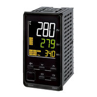
Digital Temperature Controllers
Brand: Omron
|
Category: Controller
|
Size: 16.37 MB
Table of Contents
-
Preface
3
-
Terms and Conditions Agreement
4
-
Application Considerations
5
-
Disclaimers
5
-
-
Safety Precautions
6
-
Definition of Precautionary Information
6
-
Symbols
6
-
-
Precautions for Safe Use
9
-
Installation Precautions
12
-
Precautions for Operation
13
-
Shipping Standards
13
-
Preparations for Use
14
-
Versions
15
-
Revision History
16
-
Conventions Used in this Manual
17
-
Model Notation
17
-
Meanings of Abbreviations
17
-
How to Read Display Symbols
18
-
How this Manual Is Organized
18
-
Related Manuals
18
-
-
Sections in this Manual
19
-
Table of Contents
20
-
Introduction
25
-
-
Appearance, Features, and Functions of the E5@C
26
-
Appearance
26
-
Features
26
-
Main Functions
27
-
-
I/O Configuration and Model Number Legend
29
-
I/O Configuration
29
-
Model Number Legends
30
-
Preparations
39
-
-
-
Installation
40
-
Dimensions (Unit: MM)
40
-
Panel Cutout (Unit: MM)
44
-
Mounting
47
-
-
Using the Terminals
62
-
E5CC Terminal Block Wiring Example
62
-
E5CC-U Terminal Block Wiring Example
67
-
E5CC-B Terminal Block Wiring Example
70
-
E5EC/E5AC Terminal Block Wiring Example
74
-
E5EC-B Terminal Block Wiring Example
79
-
E5DC Terminal Block Wiring Example
84
-
E5DC-B Terminal Block Wiring Example
87
-
E5GC Terminal Block Wiring Example
90
-
Precautions When Wiring
93
-
Wiring
99
-
-
Insulation Block Diagrams
111
-
Using the Setup Tool Port
114
-
Procedure
114
-
Connection Method
114
-
Installing the Driver
121
-
-
Basic Application Flow
124
-
Power on
125
-
Part Names, Part Functions, and Setting Levels
126
-
Part Names and Functions
126
-
Entering Numeric Values
131
-
Setting Levels
132
-
-
Procedures after Turning on the Power Supply
135
-
Basic Flow of Operations
135
-
Basic Procedure
135
-
Basic Operation
143
-
-
-
Moving between Setting Levels
145
-
Moving to the Initial Setting Level
145
-
Moving to the Adjustment Level
146
-
Moving to the Protect Level
146
-
Moving to the Advanced Function Setting Level
147
-
Moving to the Communications Setting Level
149
-
-
Initial Setting Examples
150
-
Setting the Input Type
153
-
Input Type
153
-
-
Selecting the Temperature Unit
155
-
Temperature Unit
155
-
-
Selecting PID Control or ON/OFF Control (Not Supported for Position-Proportional Models.)
156
-
Setting Output Specifications
157
-
Control Periods (Not Supported for Position-Proportional Models.)
157
-
Direct and Reverse Operation
157
-
Assigned Output Functions (Assigning Control Outputs Is Not Supported for Position-Proportional Models.)
158
-
Auxiliary Output Opening or Closing in Alarm
161
-
-
Setting the Set Point (SP)
162
-
Changing the SP
162
-
-
Using ON/OFF Control (Not Supported for Position-Proportional Models.)
163
-
ON/OFF Control
163
-
Hysteresis
163
-
Settings
164
-
-
Determining PID Constants(AT, ST, Manual Setup)
166
-
Determining PID Constants (AT, ST, Manual Setup)
166
-
AT (Auto-Tuning)
166
-
ST (Self-Tuning) (Not Supported for Position-Proportional Models.)
169
-
RT (Robust Tuning) (Used for at or ST.)
170
-
Manual Setup
172
-
-
Alarm Outputs
174
-
Alarm Types
174
-
Alarm Values
177
-
-
Alarm Hysteresis
180
-
Standby Sequence
180
-
Alarm Latch
181
-
-
Using Heater Burnout (HB) and Heater Short (HS) Alarms (Not Supported for Position-Proportional Models.)
182
-
HB Alarm
182
-
HS Alarm
184
-
Installing Current Transformers (CT)
186
-
Calculating Detection Current Values
188
-
Application Examples
188
-
-
Customizing the PV/SP Display
192
-
PV/SP Display Selections
192
-
Advanced Operations
195
-
-
-
Shifting Input Values
197
-
Setting Scaling Upper and Lower Limits for Analog Inputs
199
-
Executing Heating/Cooling Control (Not Supported for Position-Proportional Models.)
201
-
Heating/Cooling Control
201
-
-
Using Event Inputs
205
-
Event Input Settings
205
-
How to Use the Multi-SP Function
205
-
Operation Commands Other than Multi-SP
206
-
-
Setting the SP Upper and Lower Limit Values
209
-
Set Point Limiter
209
-
Setting
210
-
-
Using the SP Ramp Function to Limit the SP Change Rate
211
-
SP Ramp
211
-
-
Using the Key Protect Level
213
-
Protection
213
-
Entering the Password to Move to the Protect Level
214
-
-
Displaying Only Parameters that Have Been Changed
216
-
Displaying Changed Parameters
216
-
-
OR Output of Alarms
218
-
Integrated Alarm
218
-
-
Alarm Delays
220
-
Loop Burnout Alarm (Not Supported for Position-Proportional Models.)
222
-
Loop Burnout Alarm (LBA)
222
-
-
Performing Manual Control
226
-
Manual MV
226
-
-
Using the Transfer Output for the Process Value, Set Point, or Other Data
230
-
Transfer Output Function
230
-
Simple Transfer Output Function
233
-
-
Using the Simple Program Function
236
-
Simple Program Function
236
-
Operation at the Program End
239
-
Application Example Using a Simple Program
241
-
-
Output Adjustment Functions
242
-
Output Limits
242
-
MV at Stop
242
-
MV at PV Error
243
-
-
Using the Extraction of Square Root Parameter
245
-
Extraction of Square Roots
245
-
-
Setting the Width of MV Variation
247
-
MV Change Rate Limit
247
-
-
Setting the PF Key
249
-
PF Setting (Function Key)
249
-
-
Displaying PV/SV Status
252
-
PV and SV Status Display Functions
252
-
-
Using a Remote SP
254
-
Controlling Valves (Can be Used with a Position-Proportional Model)
256
-
Logic Operations
259
-
The Logic Operation Function (CX-Thermo)
259
-
Using Logic Operations
259
-
Using Status Display Messages
267
-
-
Initializing Settings
269
-
Parameters
269
-
-
Conventions Used in this Section
272
-
Protect Level
273
-
Operation Level
277
-
Adjustment Level
288
-
Monitor/Setting Item Level
308
-
Manual Control Level
309
-
Initial Setting Level
311
-
Advanced Function Setting Level
331
-
Communications Setting Level
366
-
User Calibration
369
-
-
7-1 User Calibration
371
-
Parameter Structure
371
-
Thermocouple Calibration
372
-
Resistance Thermometer Calibration
375
-
Calibrating Analog Input
377
-
Calibrating the Transfer Output
381
-
Checking Indication Accuracy
383
-
Appendices
387
-
-
Specifications
387
-
A-1-1 Ratings
387
-
A-1-2 Characteristics
387
-
A-1-3 Rating and Characteristics of Options
387
-
A-1-4 Waterproof Packing
392
-
Unit Labels
392
-
A-1-6 Setup Tool Port Cover for Front Panel
393
-
A-1-7 Connector Cover of the Terminal Unit (Models with Push-In Plus Terminal Blocks
394
-
-
Current Transformer (CT
396
-
A-2-1 Specifications
396
-
A-2-2 Dimensions (Unit: MM
396
-
-
USB-Serial Conversion Cable and Conversion Cable
399
-
A-3-1 E58-CIFQ2 USB-Serial Conversion Cable
399
-
A-3-2 E58-CIFQ2-E Conversion Cable
400
-
-
Error Displays
401
-
A-5 Troubleshooting
405
-
A-5-1 Frequently Asked Questions
405
-
A-5-2 Checking Problems
408
-
-
Parameter Operation Lists
411
-
A-6-1 Operation Level
411
-
A-6-2 Adjustment Level
412
-
A-6-3 Initial Setting Level
414
-
A-6-4 Manual Control Level
418
-
A-6-5 Monitor/Setting Item Level
418
-
A-6-6 Advanced Function Setting Level
418
-
A-6-7 Protect Level
424
-
A-6-8 Communications Setting Level
424
-
A-6-9 Initialization According to Parameter Changes
425
-
-
Sensor Input Setting Range, Indication Range, Control Range
429
-
Setting Levels Diagram
430
-
Parameter Flow
431
Advertisement
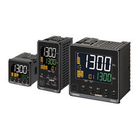
Omron E5*C-B Series Manual (137 pages)
Digital Temperature Controller
Brand: Omron
|
Category: Temperature Controller
|
Size: 42.94 MB
Omron E5*C-B Series Instruction Manual (2 pages)
Brand: Omron
|
Category: Temperature Controller
|
Size: 0.47 MB
Advertisement
Advertisement
Related Products
-
OMRON E5CK
-
Omron E5CC
-
Omron E5CD
-
Omron E5CK-T
-
Omron E5CC-*****M-002 Series
-
Omron E5CC-T**3*SM-002 Series
-
Omron E5CC-T**3*SM-003 Series
-
Omron E5CC-T**3*SM-004 Series
-
Omron E5CK-AA1-500 AC100-240
-
Omron E5CK-AA1 AC/DC24
Omron Categories
Blood Pressure Monitor
Controller
Accessories
![]()
Switch
Inverter
More Omron Manuals
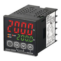
Omron E5CB это компактный, простой в эксплуатации, недорогой и надежный регулятор температуры для широкого спектра задач.
Основные особенности:
- Отличная четкость, символы высотой 16.2 мм
- монтажная глубина всего 60 мм
- настройка минимального числа параметров для начала работы
- время дискретизации всего 250 мс
- Напряжение питания 100-240 VAC или 24 VAC/VDC
Терморегуляторы Omron E5CB разработаны с учетом особенностей и требований для задач регулирования температуры в простых установках и системах.
| Размер | Напряжение питания | Тип входа | Аварийный выход | Тип выхода | Модель |
|---|---|---|---|---|---|
| 48 * 48 мм | 100 — 240 VAC | Термопара | 1 | Релейный выход | E5CB-R1TC |
| Платиновый термометр сопротивления | E5CB-R1P | ||||
| Термопара | Выход по напряжению (для управления твердотельными реле) | E5CB-Q1TC | |||
| Платиновый термометр сопротивления | E5CB-Q1P | ||||
| 24 VAC/VDC | Термопара | Релейный выход | E5CB-R1TCD | ||
| Платиновый термометр сопротивления | E5CB-R1PD | ||||
| Термопара | Выход по напряжению(для управления твердотельными реле) | E5CB-Q1TCD | |||
| Платиновый термометр сопротивления | E5CB-Q1PD |
| Item | E5CB |
|---|---|
| Power supply voltage | 100 to 240 VAC 50/60 Hz, 24 VAC 50/60 Hz, or 24 VDC |
| Operating voltage range | 85% to 110% of rated supply voltage |
| Power consumption | Approx. 3.5 VA (100 to 240 VAC) Approx. 3.5 VA (24 VAC) Approx. 2.5 W (24 VDC) |
| Sensor input | Models with thermocouple inputs Thermocouple: K, J, T, R, or S (JIS C 1602-1995, IEC60584-1) |
| Models with platinum resistance thermometer inputs Platinum resistance thermometer: Pt100 (JIS C 1604-1997, IEC60751) |
|
| Control output | SPST-NO, 250 VAC, 3 A (resistive load), electrical life: 100,000 operations, minimum applicable load: 5 V, 10 mA |
| Output voltage: 12 VDC +25%/−15% (PNP), max. load current: 21 mA, with short-circuit protection circuit | |
| Alarm output | SPST-NO, 250 VAC, 1 A (resistive load), electrical life: 100,000 operations, minimum load: 5 V, 10 mA |
| Control method | ON/OFF control or 2-PID control (with auto-tuning) |
| Setting method | Digital setting using front panel keys |
| Indication method | 7-segment digital display and individual indicators Character height: 16.2 mm (PV) |
| Other functions | Temperature input shift, run/stop, protection functions, etc. |
| Ambient operating temperature | −10 to 55°C (with no condensation or icing)/With a three-year guarantee: −10 to 50°C |
| Ambient operating humidity | 25% to 85% |
| Storage temperature | −25 to 65°C (with no condensation or icing) |
| Size in mm (H x W x D) | 48x48x65 |

Регулятор температуры цифровой серии E5CB, выход напряжения для управления ТТР (12 V DC, 21 mA), вход для термопары типа K, J, T, R или S, выход сигнализации (250 VAC, 1 A), напряжение питания 100..240 V AC, размеры 48х48 мм

Регулятор температуры цифровой серии E5CB, выход напряжения для управления ТТР (12 V DC, 21 mA), вход для термопары типа K, J, T, R или S, выход сигнализации (250 VAC, 1 A), напряжение питания 24 V AC/DC, размеры 48х48 мм

Регулятор температуры цифровой серии E5CB, релейный выход (250 V AC, 3 A), вход для термопары типа K, J, T, R или S, выход сигнализации (250 VAC, 1 A), напряжение питания 100..240 V AC, размеры 48х48 мм

Регулятор температуры цифровой серии E5CB, релейный выход (250 V AC, 3 A), вход для термопары типа K, J, T, R или S, выход сигнализации (250 VAC, 1 A), напряжение питания 24 V AC/DC, размеры 48х48 мм
Ordering information
|
Size |
Power supply voltage |
Input type |
Alarm output |
Control output |
Order code |
|---|---|---|---|---|---|
|
E5CB |
100 to 240 VAC |
Thermocouple |
1 |
Relay output |
E5CB-R1TC |
|
Platinum resistance thermometer |
E5CB-R1P |
||||
|
Thermocouple |
Voltage output |
E5CB-Q1TC |
|||
|
Platinum resistance thermometer |
E5CB-Q1P |
||||
|
24 VAC/VDC |
Thermocouple |
Relay output |
E5CB-R1TCD |
||
|
Platinum resistance thermometer |
E5CB-R1PD |
||||
|
Thermocouple |
Voltage output |
E5CB-Q1TCD |
|||
|
Platinum resistance thermometer |
E5CB-Q1PD |
Accessories
|
Option |
Order code |
|
|---|---|---|
|
USB-Serial conversion cable |
|
E58-CIFQ2 |

Software
|
Description |
Features |
|---|---|
|
ThermoMini |
Freeware/Parameter copying and cloning tool |
Specifications
|
Item |
E5CB |
|---|---|
|
Power supply voltage |
100 to 240 VAC 50/60 Hz, 24 VAC 50/60 Hz, or 24 VDC |
|
Operating voltage range |
85% to 110% of rated supply voltage |
|
Power consumption |
Approx. 3.5 VA (100 to 240 VAC) |
|
Sensor input |
Models with thermocouple inputs Thermocouple: K, J, T, R, or S (JIS C 1602-1995, IEC60584-1) |
|
Models with platinum resistance thermometer inputs Platinum resistance thermometer: Pt100 (JIS C 1604-1997, IEC60751) |
|
|
Control output |
SPST-NO, 250 VAC, 3 A (resistive load), electrical life: 100,000 operations, |
|
Output voltage: 12 VDC +25%/−15% (PNP), max. load current: 21 mA, with short-circuit protection circuit |
|
|
Alarm output |
SPST-NO, 250 VAC, 1 A (resistive load), electrical life: 100,000 operations, minimum load: 5 V, 10 mA |
|
Control method |
ON/OFF control or 2-PID control (with auto-tuning) |
|
Setting method |
Digital setting using front panel keys |
|
Indication method |
7-segment digital display and individual indicators Character height: 16.2 mm (PV) |
|
Other functions |
Temperature input shift, run/stop, protection functions, etc. |
|
Ambient operating |
−10 to 55°C (with no condensation or icing)/With a three-year guarantee: −10 to 50°C |
|
Ambient operating humidity |
25% to 85% |
|
Storage temperature |
−25 to 65°C (with no condensation or icing) |
|
Size in mm (H × W × D) |
48×48×65 |
Note: Other models (E5C_L/E5EW) with similar features but without USB communication are only available for “Emerging Countries”. Please ask you local Sales representative for further information.