Преимущества:
- Простая настройка с помощью поворотных и DIP- переключателей.
- Универсальный вход (термопара/платиновый термометр сопротивления).
- Цифровой дисплей с четкой индикацией, с высотой символов 13,5 мм.
- Соответствие RoHS
Перечень моделей
| Напряжение источника питания | Количество аварийных сигналов | Управляющий выход | Универсальный вход TC/Pt С клеммной крышкой |
| 100…240 В~ | 1 | Реле Напряжение (для управления ТТР) |
E5CSV-R1T-500 E5CSV-Q1T-500 |
| 24 В~/= | 1 | Реле Напряжение (для управления ТТР) |
E5CSV-R1TD-500 E5CSV-Q1TD-500 |
Номинальные параметры
| Напряжение питания | 100…240 В~, 50/60 Гц |
| Потребляемая мощность | 5 ВА |
| Вход датчика | Универсальный вход для термопары/платинового термометра сопротивления типа: K, J, L, T, U, N, R, Pt100, JPt100 |
| Релейный выход | 1 НР (SPST-NO), 250 В~, 3 А (резистивная нагрузка) |
| Выход напряжения (для управления твердотельным реле) | 12 В=, 21 мА (со схемой защиты от короткого замыкания) |
| Метод регулирования | Дискретное регулирование (ВКЛ/ВЫКЛ) или регулирование 2-ПИД (с автоматической настройкой) |
| Выход аварийного сигнала | 1 НР (SPST-NO), 250 В~, 1A (резистивная нагрузка) |
| Способ настройки | Цифровая настройка при помощи кнопок на передней панели (настройка функций при помощи DIP-переключателя) |
| Способ индикации | «3+1/2»-разрядный, 7-сегментный цифровой индикатор (с высотой символов 13,5 мм) + индикаторы отклонения |
| Прочие функции | Запрет перенастройки (блокировка кнопок)Смещение входного сигнала Выбор шкалы температуры (°C/°F)Работа в прямом/обратном направлении Переключение интервала регулирования8 типов сигнализируемых аварий Обнаружение ошибки датчика |
| Температура окружающего воздуха | От -10 до 55°C (без обледенения или конденсации) |
| Влажность окружающего воздуха | От 25% до 85% |
| Температура хранения | От -25 до 65°C (без обледенения или конденсации) |
Характеристики
| Гистерезис (при регулировании ВКЛ/ВЫКЛ) | 0,1% полной шкалы |
| Пропорциональный диапазон (P) | От 1 до 999°C (автоматическая регулировка при помощи автоматической настройки и самонастройки) |
| Постоянная интегрирования (I) | От 1 до 1999 с (автоматическая регулировка при помощи автоматической настройки и самонастройки) |
| Постоянная дифференцирования (D) | От 1 до 1999 с (автоматическая регулировка при помощи автоматической настройки и самонастройки) |
| Диапазон выхода сигнализации аварий | Абсолютное значение тревоги: Совпадает с диапазоном регулирования В остальных случаях: От 0% до 100% полной шкалы Гистерезис при сигнализации аварий: 0,2°C или °F (фиксированный) |
| Интервал регулирования | 2/20 с |
| Период измерения | 500 мс |
| Сопротивление изоляции | Мин. 20 МОм (при 500 В=) |
| Электрическая прочность диэлектрика | 2000 В~, 50/60 Гц в течение 1 минуты между токоведущими клеммами разной полярности |
| Отказ | 10…55 Гц, 20 м/с2 в течение 10 минут по каждой из осей X, Y и Z |
| Разрушение | 10 … 55 Гц, с одинарной амплитудой 0,75 мм в течение 2 часов по каждой из осей X, Y и Z |
| Отказ | Минимум 100 м/с2, по 3 раза в каждом из 6 направлений |
| Разрушение | Минимум 300 м/с2, по 3 раза в каждом из 6 направлений |
| Электрич. ресурс | Минимум 100 000 циклов (модели с релейным выходом) |
| Вес | Приблиз. 120 г (только регулятор) |
| Степень защиты | Передняя панель: эквивалент IP66; Тыльная сторона: IP20; Клеммы: IP00 |
| Защита памяти | EEPROM (энергонезависимая память) (число операций записи: 1 000 000) |
| Электромагнитная совместимость | Излучение в эфир: EN 55011 Группа 1, Класс A Излучение в питающую сеть: EN 55011 Группа 1, Класс A Устойчивость к электростатическому разряду: EN 61000-4-2: разряд при напряжении между контактами 4 кВ (уровень 2) разряд через воздух при напряжении 8 кВ (уровень 3) Устойчивость к электромагнитным излучениям: EN 61000-4-3: 10 В/м (80…1000 МГц; 1,4…2,0 ГГц с амплитудной модуляцией) (уровень 3) 10 В/м (900 МГц с импульсной модуляцией) Устойчивость к индуцированным радиопомехам: EN 61000-4-6: 3 В (0,15 … 80 МГц) (уровень 2) Помехоустойчивость (устойчивость к быстрым переходным напряжениям): EN 61000-4-4 Устойчивость к быстрым переходным помехам: линия питания – 2 кВ (уровень 3), линия передачи сигналов ввода/ вывода – 1 кВ (уровень 3) Устойчивость к броскам напряжения: EN 61000-4-5: Линия питания: Помехи нормального вида 1 кВ; Помехи общего вида 2 кВ Выходная линия (релейный выход): Помехи нормального вида 1 кВ; Помехи общего вида 2 кВ Устойчивость к скачкам/кратким пропаданиям напряжения питающей сети: EN 61000-4-11, 0,5 периода, 100% (номинальное напряжение) |
| Сертификаты соответствия | UL 61010C-1 (Реестр), CSA C22.2 № 1010-1 |
| Соответствие стандартам | EN 61326, EN 61010-1, IEC 61010-1, VDE 0106, Часть 100 (защита от прикосновения), при установленной крышке клеммного блока. |
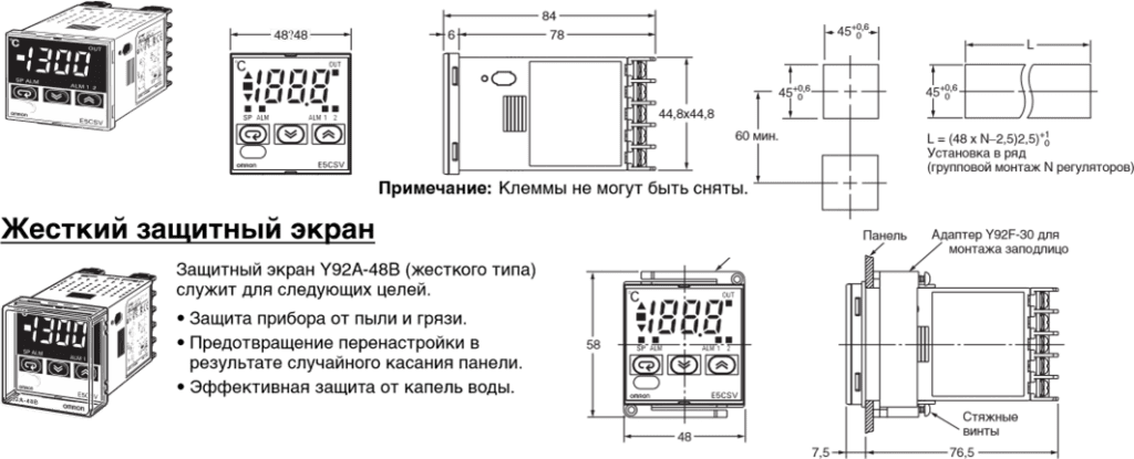
Габаритные размеры для монтажа
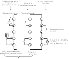
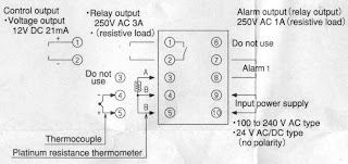
Принципиальная схема включения
Примечание:
- Выход напряжения (12 В=, 21 мА) гальванически не развязан с внутренними цепями. При работе с заземленной термопарой не подключайте к «земле» выходные клеммы 1 или 2. Иначе нежелательные пути тока вызовут ошибки измерения.
- Модели с напряжением 100…240 В~ и 24 В~/= являются отдельными устройствами. Полярность напряжения в моделях на 24 В= не имеет значения.
Главная панель
Настройка регулятора перед включением питания
- Высвободите зацепы, вставив отвёртку с плоским шлицем поочерёдно в каждую из прорезей (сверху и снизу).
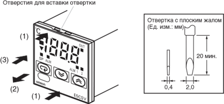
2. Вставьте отвёртку в зазор между передней панелью и корпусом и слегка вытяните переднюю панель. Захватите переднюю панель и полностью выдвиньте ее. Не прикладывайте к панели чрезмерное усилие.
3. Убедитесь в том, что резиновое уплотнение находится на месте, после чего вставьте E5CSV в корпус и вдавливайте его вглубь, пока он не зафиксируется в конечном положении. Вставив E5CSV на место, нажмите на зацепы, расположенные сзади (сверху и снизу), чтобы они надёжно защёлкнулись. Следите, чтобы внутренние электронные элементы не соприкасались с корпусом.
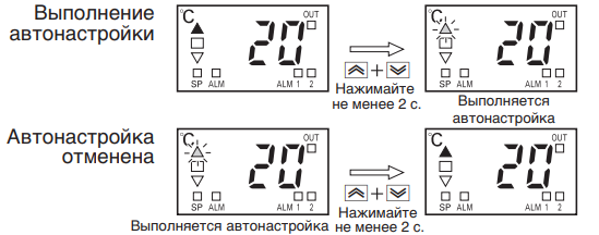
Функция автоматической настройки (AT)
Автоматическая настройка (AT) выполняется при нажатии и удержании не менее 2 с клавиш ![]() U Up (Больше) и
U Up (Больше) и ![]() D Down (Меньше), когда на дисплее отображается текущее значение (PV). Во время выполнения автоматической настройки мигают индикаторы отклонения. Если описанные действия будут выполнены в процессе текущей операции автоматической настройки, автоматическая настройка будет отменена. По завершению автоматической настройки мигание индикаторов прекращается.
D Down (Меньше), когда на дисплее отображается текущее значение (PV). Во время выполнения автоматической настройки мигают индикаторы отклонения. Если описанные действия будут выполнены в процессе текущей операции автоматической настройки, автоматическая настройка будет отменена. По завершению автоматической настройки мигание индикаторов прекращается.
Примечание:
Один из индикаторов отклонения будет мигать.
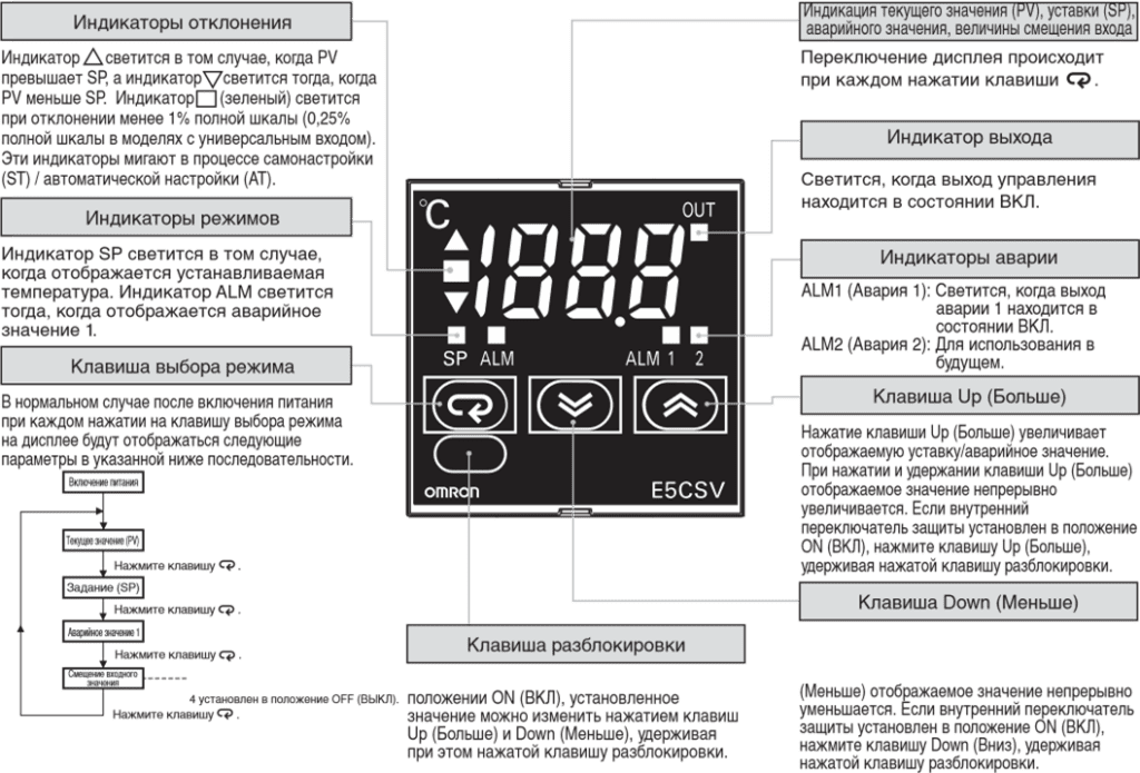
Порядок отображения показаний при нажатии клавиши выбора режима
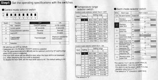
- Если после изменения температурного диапазона уставка (SP) оказывается за пределами диапазона, в первую очередь будет отображено значение уставки. При этом в качестве уставки будет автоматически установлено ближайшее к ней минимальное или максимальное значение.
- Если после изменения температурного диапазона установленное аварийное значение оказывается за пределами диапазона, в первую очередь будет отображено аварийное значение. При этом в качестве аварийного значения будет автоматически установлено максимальное значение нового температурного диапазона.
Настройка
Для выбора режима регулирования служат переключатели режима регулирования. (Изначально все микропереключатели находятся в положении ВЫКЛ)
Примечание:
- Прежнее наименование Pt100 изменено на JPt100 в соответствии с изменениями в JIS.
- Прежнее наименование J-DIN изменено на L в соответствии с изменениями в стандартах DIN.
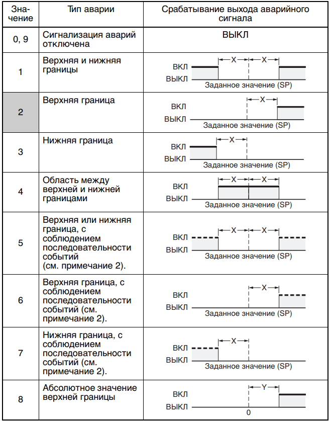
Режимы сигнализации аварий
Чтобы изменить режим сигнализации аварий, выберите соответствующий номер типа аварии переключателем
Примечание:
- Аварии не сигнализируются. Если установлено значение 0 или 9, аварийное значение (индикация аварии) не будет отображаться даже при нажатии клавиши выбора. Диапазон установки аварийных значений X: от 0 до макс. значения шкалы; Y: В пределах температурного диапазона Значение X является величиной отклонения для заданной уставки (SP).
- Функция последовательности событий для режима ожидания (выполняется при включенном питании).
Список ошибок
| Состояние дисплея | Причина | Управляющий выход |
| PV отображается как fff | Текущее значение больше верхнего предела диапазона регулирования температуры (переполнение). | Управление нагревом (обратное управление): ВЫКЛ Управление охлаждением (прямое управление): ВКЛ |
| PV отображается как — | Текущее значение меньше нижнего предела диапазона регулирования температуры (потеря значимости). | Управление нагревом (обратное управление): ВКЛ Управление охлаждением (прямое управление): ВЫКЛ |
| fff (мигает) | Модели со входом для термопары и модели со входом для платинового термометра сопротивления: Текущее значение больше температуры переполнения или произошла ошибка датчика. Модели с универсальным входом (термопара/платиновый термометр сопротивления): Текущее значение больше верхнего предела диапазона регулирования температуры или произошла ошибка датчика. | ВЫКЛ |
| — (мигает) | Вход для термопары и платинового термометра сопротивления: Текущее значение меньше температуры потери значимости или произошла ошибка датчика. Термопары: Обратная полярность.Модели с универсальным входом (термопара/платиновый термометр сопротивления): Текущее значение меньше нижнего предела диапазона регулирования температуры или произошла ошибка датчика. | ВЫКЛ |
| Отображается e11 | Ошибка памяти (E11). Выключите и снова включите питание. Если индикация ошибки не исчезает, регулятор нуждается в ремонте. | Выходы регулирования и сигнализации аварий выключаются. |
Скачать полную документацию.
RU
-
Contents
-
Table of Contents
-
Bookmarks
Related Manuals for Omron E5CSV
Summary of Contents for Omron E5CSV
-
Page 1
E5CSV E5CSV E5CSV E5CSV E5CSV E5CSV E5CS-U E5CS-U E5CS-U E5CS-U E5CS-U E5CS-U Digital Temperature Controller User’s Manual Cat. No. H140-E1-02… -
Page 3
Conforms to UL, CSA, and IEC safety standards and EMC Directive. This manual describes the E5CSV and E5CS-U. Read this manual thoroughly and be sure you understand it before attempting to use the Compact Digital Temperature Controller and use the Compact Digital Temperature Controller correctly according to the information provided. -
Page 4: Warranty And Limitations Of Liability
PRODUCTS, WHETHER SUCH CLAIM IS BASED ON CONTRACT, WARRANTY, NEGLIGENCE, OR STRICT LIABILITY. In no event shall the responsibility of OMRON for any act exceed the individual price of the product on which liability is asserted. IN NO EVENT SHALL OMRON BE RESPONSIBLE FOR WARRANTY, REPAIR, OR OTHER CLAIMS…
-
Page 5
Performance data given in this manual is provided as a guide for the user in determining suitability and does not constitute a warranty. It may represent the result of OMRON’s test conditions, and the users must correlate it to actual application requirements. Actual performance is subject to the OMRON Warranty and Limitations of Liability. -
Page 6: Safety Precautions
Safety Precautions Definition of Precautionary Information The following notation is used in this manual to provide precautions required to ensure safe usage of the product. The safety precautions that are provided are extremely important to safety. Always read and heed the information provided in all safety precautions. The following notation is used.
-
Page 7
Loose screws may occasionally result in fire. Tighten terminal screws to the specified torque (E5CSV: 0.74 to 0.90 N·m, E5CS-U: 0.5 N·m). Unexpected operation may result in equipment damage or accidents if the settings are not appropriate for the controlled system. -
Page 8: Precautions For Safe Use
Precautions for Safe Use Be sure to observe the following precautions to prevent operation failure, malfunction, or adverse affects on the performance and functions of the product. Not doing so may occasionally result in unexpected events. 1) The product is designed for indoor use only. Do not use the product outdoors or in any of the following locations.
-
Page 9
13) A switch or circuit breaker should be provided close to this Unit. The switch or circuit breaker should be within easy reach of the operator, and must be marked as a disconnecting means for this unit. 14) Approximately 30 minutes is required for the correct temperature to be displayed after turning the power supply to the Temperature Controller ON. -
Page 10: Installation Precautions
Waterproofing The degree of protection is as shown below. Sections without any specification on their degree of protection or those with IP@0 are not waterproof. E5CSV: Front panel IP66, rear case IP20, terminals IP00 E5CS-U: Front panel IP50, enclosure rating 2 (IEC 60529),…
-
Page 11: Precautions For Operation
Do not subject the terminal screws to excessive stress (force) when tightening them. Make sure that there are no loose screws after tightening terminal screws to the specified torque (E5CSV: 0.74 to 0.9 N·m, E5CS-U: 0.5 N·m). Be sure to confirm the polarity for each terminal before wiring the terminal block and connectors.
-
Page 12: Revision History
Revision History A manual revision code appears as a suffix to the catalog number on the back cover of the manual. H140-E1-02 Cat. No. The following table outlines the changes made to the manual during each revision. Page numbers refer to the previous version.
-
Page 13: Conventions Used In This Manual
Conventions Used in This Manual Model Notations “E5CSV and E5CS-U” or “E5CSV/E5CS-U” are used when the information being provided applies to all E5CSV and E5CS-U Digital Temperature Controllers. Meanings of Abbreviations The following abbreviations are used in parameter names, figures and in text explanations. These…
-
Page 14: About This Manual
Temperature Controllers for operation, including installation and wiring. Section 3 describes the basic ● Basic Operations Section 3 Basic operation of the E5CSV/E5CS-U Operations Digital Temperature Controllers, Section 5 Parameters including key operations to set parameters and descriptions of display elements based on specific control examples.
-
Page 15: Table Of Contents
■ External Dimensions (Unit: mm)…………2-2 ■ Panel Cutout Dimensions (Unit: mm) ……….2-2 ■ Mounting………………… 2-3 ■ Removing the E5CSV from the Case……….2-3 2.2 Wiring Terminals ………………..2-5 ■ Terminal Arrangement ……………. 2-5 ■ Precautions when Wiring…………..2-5 ■…
-
Page 16
■ Changing the SP …………….3-7 3.6 Using ON/OFF Control………………3-8 ■ ON/OFF Control …………….. 3-8 3.7 Determining PID Constants (AT, ST, Manual Setup)………. 3-9 ■ AT (Auto-tuning)……………… 3-9 ■ ST (Self-tuning) …………….3-10 ■ Manual Setup ………………. 3-12 3.8 Alarm Outputs ………………..3-14 ■… -
Page 18: Section 1 Overview
■ Using the Keys…………1-3 ● M (Mode) Key …………1-3 ● U (Up) Key…………1-3 ● D (Down) Key …………1-3 ● Lock Release Key (E5CSV only)……1-3 1.2 I/O Configuration and Main Functions ……. 1-4 ■ I/O Configuration…………1-4 ● E5CSV and E5CS-U ………..1-4 ■…
-
Page 19: Names Of Parts
Section 1 Overview 1.1 Names of Parts ■ Front Panel ● E5CSV ● E5CS-U Deviation indicators Temperature display Tool insertion hole Temperature display Deviation Output indicator indicators Output indicator Mode Alarm indicators indicators Alarm indicators Mode Up Key Mode Key…
-
Page 20: Using The Keys
Holding the key down speeds up the decrementation. ● Lock Release Key When the protect switch is ON, the set value can be changed by pressing the U and D Keys while holding down the Lock Release (E5CSV only) Key.
-
Page 21: I/O Configuration And Main Functions
1 assignment, and the alarm 2 assignment in the initial setting level. ■ Basic Model Number ● Models with Terminal Blocks E5CSV — @ @ @ @ -@ Case color Blank: Black W : Light gray…
-
Page 22: Control Outputs
● Alarms • Alarms are supported by E5CSV-@1@@-@, E5CSV-@2@@-@, E5CS-@1@@U-@, and E5CS-@2@@U-@. Set the alarm classification and alarm value or the alarm’s upper and lower limits. If necessary, a more comprehensive alarm function can be achieved by setting the standby sequence, close in alarm/open in alarm, and alarm latch parameters.
-
Page 23: Setting Level Configuration And Key Operations
Parameters are divided into groups, each called a “level.” Each of the set values (setting items) in these levels is called a “parameter.”. The parameters on the E5CSV/E5CS-U are divided as follows: When the power is turned ON, “0” will be displayed for approximately one second.
-
Page 24: Selecting Parameters
1.3 Setting Level Configuration and Key Operations ■ Selecting • Within each level, the parameter is changed each time the M Key is pressed. Parameters The parameter changes immediately after pressing the M key. Parameter Parameter Parameter Parameter ■ Fixing Settings •…
-
Page 25: Setting Switches
Section 1 Overview 1.4 Setting Switches ● E5CSV • Insert the tool (refer to the diagram) into the two tool insertion holes (one on the top and one on the bottom) and release the hooks. Then, grip the front panel and pull out towards you to remove it.
-
Page 26: Protect Switch
1.4 Setting Switches Control mode switches INIT switch Temperature range switch Protect switch Alarm mode switch ● Protect Switch • When the protect switch is ON, Up Key and Down Key operations are prohibited to prevent setting mistakes. • The Mode Key, however, can also be operated even if the protect switch is ON.
-
Page 27: Temperature Range Switch
Section 1 Overview ● Temperature • Set the temperature range using the temperature range switch numbers. Range Switch Thermocouple input (E5CSV-@ KJ, E5CS-@ KJU) Tem- Set range Speci- per- fica- °C °F ature tions range J or L * The default is 2.
-
Page 28
°C °F ature tions range − 50 − 50 − 50 − 50 * The default is 1. Multi-input (thermocouple/platinum resistance thermometer) models (E5CSV-@T, E5CS-@TU) Control mode switch 5: OFF Tem- Setting range Speci- per- fica- °C °F ature tions range −… -
Page 29: Alarm Mode Switch
Section 1 Overview ● Alarm Mode • Select the alarm mode switch number when changing to the alarm mode. This switch is not provided in models without alarms.) Switch Alarm output Alarm type value operation Alarm function OFF Output OFF Upper- and lower-limit Upper-limit Lower-limit…
-
Page 30: Section 2 Preparations
● E5CS-U…………… 2-3 ● Mounting to the Panel ……… 2-3 ● Mounting the Terminal Cover ……2-3 ■ Removing the E5CSV from the Case ……2-3 2.2 Wiring Terminals …………..2-5 ■ Terminal Arrangement ……….2-5 ● E5CSV …………..2-5 ●…
-
Page 31: Installation
94.45 (7.75) 6.25 72.5 14.2 44.8 44.8 ■ Panel Cutout Dimensions (Unit: mm) ● E5CSV and E5CS-U Individual Mounting Group Mounting (48 × Number of Units – 2.5) +1.0 +0.6 • The recommended panel thickness is 1 to 4 mm.
-
Page 32: Mounting
0.29 to 0.39 N·m. ● Mounting the For the E5CSV, make sure that the “UP” mark is facing up, and then fit the terminal cover into the holes on the top and bottom. Terminal Cover * Order the E53-COU10 Terminal Cover separately.
-
Page 33
Be sure not to impose excessive force on the panel. (3) When inserting the E5CSV, check to make sure that the sealing rubber is in place and push the E5CSV toward the rear case until it snaps into position. While pushing the E5CSV into place, push down on the hooks on the top and bottom surfaces of the rear case so that the hooks are securely locked in place. -
Page 34: Wiring Terminals
2.2 Wiring Terminals 2.2 Wiring Terminals ■ Terminal Arrangement ● E5CSV Relay output Alarm output (relay output), ① ⑥ 250 VAC, 3 A 250 VAC, 1 A (resistive load) (Resistive load) Control output ② ⑦ Alarm 2 − Voltage output…
-
Page 35: Precautions When Wiring
● Power Supply • With the E5CSV, connect to terminals 9 and 10. For the E5CS-U with alarms, connect to terminals 10 and 11, and for E5CS-U models without alarms, connect to terminals 7 and 8. The following table shows the specifications.
-
Page 36: Control Outputs
2.2 Wiring Terminals ● Control Outputs • Outputs are sent from terminals 1 and 2 with the E5CSV, and from terminals 4 to 6 with the E5CS-U. The following diagrams show the available outputs and their internal equalizing circuits. ④…
-
Page 37: Section 3 Basic Operations
Section 3 Basic Operations 3.1 Setting the Input Type …………..3-2 ■ Input Type …………..3-2 ● Thermocouple…………. 3-2 ● Platinum Resistance Thermometer….. 3-2 ● Thermistor …………3-3 ● Multi-input (Thermocouple/Platinum Resistance Thermometer) Models ……..3-3 3.2 Selecting the Temperature Unit ………… 3-4 ●…
-
Page 38: Setting The Input Type
Section 3 Basic Operations 3.1 Setting the Input Type The E5CS is available in models with thermocouple input, models with platinum resistance thermometer input, thermistor input, and multi-input (thermocouple/platinum resistance thermometer) models. The type of Sensor that can be used depends on the model. Confirm the model that was purchased, and set the Sensor to be used and the temperature range switch.
-
Page 39: Thermistor
3.1 Setting the Input Type ● Thermistor Temper- Specifications Input temperature range ature range (°F) 6 KΩ (0°C) (°C) (°F) 6 KΩ (0°C) (°C) (°F) 30 KΩ (0°C) (°C) 550 Ω (200°C) (°F) (°C) (°F) 4 KΩ (200°C) (°C) (°F) 6 KΩ…
-
Page 40: Selecting The Temperature Unit
Section 3 Basic Operations 3.2 Selecting the Temperature Unit ● Temperature Unit Select the temperature unit as either °C or °F using the control • mode switch 6. • The default is OFF (°C).
-
Page 41: Selecting Pid Control Or On/Off Control
3.3 Selecting PID Control or ON/OFF Control 3.3 Selecting PID Control or ON/OFF Control Two control methods are supported: 2-PID control and ON/OFF control. Switching between 2-PID control and ON/OFF control is performed using the control mode switch 1. When this parameter is set to ON, 2-PID control is selected, and when it is set to OFF, ON/OFF control is selected.
-
Page 42: Setting Output Specifications
Section 3 Basic Operations 3.4 Setting Output Specifications ■ Control Period • Set the output period (control period). Though a shorter period provides better control performance, it is recommended that the control period be set to 20 seconds or longer for a relay output to preserve the service life of the relay.
-
Page 43: Setting The Set Point (Sp)
3.5 Setting the Set Point (SP) 3.5 Setting the Set Point (SP) The operation level is displayed when the power is turned ON. When the M Key is used to light the SP indicator in the display, the set point is displayed.
-
Page 44: Using On/Off Control
Section 3 Basic Operations 3.6 Using ON/OFF Control In ON/OFF control, the control output turns OFF when the temperature being controlled reaches the preset set point. When the manipulated variable turns OFF, the temperature begins to fall and the control turns ON again. This operation is repeated over a certain temperature range. At this time, the amount that the temperature must fall before control turns ON again is determined by the “hysteresis”…
-
Page 45: Determining Pid Constants (At, St, Manual Setup)
3.7 Determining PID Constants (AT, ST, Manual Setup) 3.7 Determining PID Constants (AT, ST, Manual Setup) ■ AT (Auto-tuning) • When AT is executed, the optimum PID constants for the set point at that time are set automatically. A method (called the limit cycle method) for forcibly changing the manipulated variable and finding the characteristics of the control target is employed.
-
Page 46: St (Self-Tuning)
Section 3 Basic Operations ■ ST (Self-tuning) ST (self-tuning) is a function that finds PID constants by using step response tuning (SRT) when Controller operation begins or when the set point is changed. Once the PID constants have been calculated, ST is not executed when the next control operation is started as long as the set point remains unchanged.
-
Page 47: St Stable Range
3.7 Determining PID Constants (AT, ST, Manual Setup) ● ST Stable Range The ST stable range determines the set value under which ST Operating Procedure (self-tuning) functions operate. This procedure sets the ST stable range to 20°C. Initial setting level (1) Press the M Key from the initial setting level (1) and select “ST stable range”…
-
Page 48: Manual Setup
Section 3 Basic Operations ■ Manual Setup The manual settings for PID constants are performed separately in the “proportional band” (P), “integral time” (I), and “derivative time” (D) parameters in the initial setting level (2). When PID constants are set manually, the tuning setting enabled in the initial setting level (1) is automatically changed to AT (auto-tuning), and ST (self-tuning) is disabled.
-
Page 49
3.7 Determining PID Constants (AT, ST, Manual Setup) • When P (Proportional Band) Is Adjusted The curve rises gradually, and a long stabilization time is created, Increas- but overshooting is prevented. ing P Overshooting and hunting occur, but the set value is quickly reached creas and the temperature stabilizes. -
Page 50: Alarm Outputs
Section 3 Basic Operations 3.8 Alarm Outputs • Alarms can be used with E5CS@1@@-@ (one alarm point), E5CS@2@@-@ (two alarm points), E5CS@1@@U-@ (one alarm point), and E5CS@2@@U-@ (two alarm points). Alarm output conditions are determined by a combination of the “alarm type” and “alarm value”. •…
-
Page 51
3.8 Alarm Outputs Alarm mode switch Set the alarm mode switch to 2 and then turn ON the power. Press the M Key in the operation level and select the “alarm value 1” (ALM mode) parameter. Power ON Process value Use the U Key to set the parameter to 10. -
Page 52: Shifting Input Values
Section 3 Basic Operations 3.9 Shifting Input Values ■ Shifting Inputs When the control mode switch 4 is set to ON, the input shift value is displayed in the operation level and the shift can be added to the input. When the control mode switch 4 is set to OFF (no input shift display), the input shift is not displayed but the shift value is enabled.
-
Page 53: Shift Method
3.9 Shifting Input Values ● Shift Method Make sure that the control target temperature (C) and Controller temperature (B) match, with the control target temperature near the set point. Check the control target temperature (B) and the Controller readout (A). Subtract the Controller readout temperature (A) from the control target temperature (B) Set the result as the input shift value.
-
Page 54: Section 4 Operations For Applications
Section 4 Operations Applications • • • 4.1 Moving to the Initial Setting Level ……..4-2 4.2 Assigning Outputs ………….4-3 ■ Output Assignment ………… 4-3 4.3 Alarm Functions …………..4-4 ■ Alarm Hysteresis …………4-4 ■ Standby Sequence ………… 4-4 ■ Alarm Latch …………… 4-4 ●…
-
Page 55: Moving To The Initial Setting Level
Section 4 Operations for Applications 4.1 Moving to the Initial Setting Level • To move to the initial setting level, turn OFF the protect switch, turn ON the INIT switch, and then hold down the U Key while turning ON the power.
-
Page 56: Assigning Outputs
4.2 Assigning Outputs 4.2 Assigning Outputs • ■ Output • By changing the control output assignment, alarm output 1 assignment, and alarm output 2 assignment settings, the functions Assignment assigned to each output can be changed in the initial setting level (3).
-
Page 57: Alarm Functions
Section 4 Operations for Applications 4.3 Alarm Functions • ■ Alarm • The hysteresis of alarm outputs when alarms are switched ON/OFF can be set as follows: Hysteresis Alarm hysteresis is always 0.2 (°C or °F). Lower-limit alarm Upper-limit alarm Alarm hysteresis Alarm hysteresis Alarm value…
-
Page 58: Close In Alarm/Open In Alarm
4.3 Alarm Functions ■ Close in • When “close in alarm” is set, the status of the alarm function will be output as is. When “open in alarm” is set, the status of the alarm Alarm/Open in function will be reversed before being output. Alarm •…
-
Page 59: Setting The Sp Upper And Lower Limit Values
Section 4 Operations for Applications 4.4 Setting the SP Upper and Lower Limit Values • ■ Set Point The setting range of the set point is limited by the set point limiter. The set point limiter is used to prevent the control target from Limiter reaching abnormal temperatures.
-
Page 60: Setting The Sp Upper And Lower Limit Values
4.4 Setting the SP Upper and Lower Limit Values • Setting the Set Point Upper-limit Value • Set Point Upper Limit = 1000 Operating Procedure Initial setting level (3) Press the M Key from the initial setting level (3) and select “set point upper limit”…
-
Page 61: Alarm Delays
Section 4 Operations for Applications 4.5 Alarm Delays • ■ Alarm Delays • Delays can be set for the alarm outputs. ON and OFF delays can be set separately for alarms 1 and 2. The ON and OFF delays for alarms 1 and 2 also apply to the individual ALM1 and ALM2 indicators.
-
Page 62: Parameters Related To Alarm Delays
4.5 Alarm Delays ● Parameters Related to Alarm Delays Set (monitor) Parameter name Setting values Initial setting level (4) Alarm 1 ON Delay 0 to 999 (s) SP mode Initial setting level (5) Alarm 2 ON Delay 0 to 999 (s) SP mode Initial setting level (4) Alarm 1 OFF Delay…
-
Page 63
Section 4 Operations for Applications 4-10… -
Page 64: Section 5 Parameters
Section 5 Parameters 5.1 Conventions Used in this Section……….5-2 ● Meanings of Icons Used in this Section ….5-2 ● About Related Parameter Displays ….. 5-2 ● The Order in Which Parameters Are Described in This Section ……..5-2 5.2 Operation Level …………….
-
Page 65: Conventions Used In This Section
Section 5 Parameters 5.1 Conventions Used in this Section ● Meanings of Icons Used in this Section Describes the functions of the parameter. Function Describes the setting range and default of the parameter. Setting ● About Related Parameter Displays Parameters are displayed only when the conditions of use indicated for the parameter are satisfied.
-
Page 66: Operation Level
5.2 Operation Level 5.2 Operation Level Display this level to perform standard control operations. The set points and alarm values are set in this level. Operation Level Power ON Page O U T IS mode (1) ・ Input shift value Page (when input shift is Process value…
-
Page 67
Section 5 Parameters Process value • Displays the process value (except when no PV display is selected) Monitor range Unit Process Input indication range Function value (See pages A-12 and A-13.) * The decimal position is set automatically by the selected Sensor. SP mode Set point •… -
Page 68
5.2 Operation Level ALM2 mode Alarm value 2 This parameter is set to the input values “X” or “Y” in the alarm type list. The ALM will flash in the display while the alarm value 2 is displayed. • This parameter sets the alarm value for alarm output 2. Function Alarm Setting range… -
Page 69
Section 5 Parameters IS mode (1) Manual reset value • This function resets the offset that occurs when P (or PD) control is used. The offset that occurs is set in °C or °F as the manual reset value. (This applies when manual reset is enabled.) Function •… -
Page 70
5.2 Operation Level IS mode (3) Alarm 1 latch status • This parameter displays the alarm 1 latch status. The latch can be cleared by pressing the U and D Keys for at least 2 s while • the alarm 1 latch status is displayed. Function •… -
Page 71: Moving To The Initial Setting Level
Section 5 Parameters 5.3 Moving to the Initial Setting Level The initial setting level is used to make the settings that maximize Temperature Controller performance. Control stops when moving to the initial setting level. The methods for moving to the initial setting level are described here.
-
Page 72: Initial Setting Level(1)
5.4 Initial Setting Leve l (1) 5.4 Initial Setting Level (1) Move to initial setting level (1) by selecting “1” in the initial setting level selection display and pressing the M Key. This level is used to set the following parameters including tuning, hysteresis for ON/OFF control.
-
Page 73
Section 5 Parameters PV auto reset PV/SP display Tuning selection SP mode ST executing display Manual reset enable/disable Control period selection • Set whether to enable or disable PV auto reset. • Set the PV/SP display. • Select the tuning method. •… -
Page 74: Initial Setting Level (1)
5.4 Initial Setting Leve l (1) 100’s digit 10’s digit 1’s digit Manual Displayed Control PV auto PV/SP Tuning reset number execution period Setting reset display selection enable/ display selection disable Disabled ST/AT 2/20 Disabled PV→SP Enabled 6/60 Enabled 2/20 Enabled ST/AT 6/60…
-
Page 75: Indicator Lights
Section 5 Parameters Integral time setting unit Hysteresis width ALM mode Temperature width in which the ■ deviation indicator lights • Select the integral time setting unit. • Set the hysteresis width. Set the temperature width in which the ■ deviation indicator lights. •…
-
Page 76: Initial Setting Level (2)
5.4 Initial Setting Leve l (1) IS mode ST stable range • The setting of this parameter determines when ST operates. Function Setting range Unit Default °C/°F 1 to 999 Setting 5-13…
-
Page 77: Initial Setting Level (2)
Section 5 Parameters 5.5 Initial Setting Level (2) Move to initial setting level (2) by selecting “2” in the initial setting level selection display and pressing the M Key. Manual PID settings can be set in this level. In the initial setting level (2), the ▲■▼deviation indicators are lit. Initial setting level (2) Page O U T…
-
Page 78: Initial Setting Level (3)
5.5 Initial Setting Level (2) SP mode Proportional band The proportional band (P) is set in this parameter. The proportional band for AT (auto-tuning) and ST (self-tuning) can also be set automatically. • P operation: Refers to control in which the MV is proportional to the deviation. Function Setting range Unit…
-
Page 79: Initial Setting Level (3)
Section 5 Parameters 5.6 Initial Setting Level (3) Move to initial setting level (3) by selecting “3” in the initial setting level selection display and pressing the M Key. The set point upper-/lower-limit values and output assignment can be set in this level. In the initial setting level (3), the ▲…
-
Page 80: Initial Setting Level (4)
5.6 Initial Setting Level (3) SP mode SP upper limit • This parameter sets the upper limit of the set point. The set point can be set within the range with the upper limit set in the “SP upper limit” parameter. If this parameter is reset, however, any set point that is outside of the new Function range will be forcibly changed to the SP upper limit.
-
Page 81
Section 5 Parameters IS mode (1) Control output assignment • This parameter sets the function to be assigned to the control output. Function Displayed Set value Setting range Default number No assignment Setting Control function 0 to 3 1: Control function Alarm 1 function Alarm 2 function IS mode (2) -
Page 82: Initial Setting Level (5)
5.6 Initial Setting Level (3) IS mode (3) Alarm 2 assignment • This parameter sets the function to be assigned to alarm output 2. Function Displayed Set value Setting range Default number Setting No assignment Control function 0 to 3 3: Alarm 2 function Alarm 1 function Alarm 2 function…
-
Page 83: Initial Setting Level (4)
Section 5 Parameters 5.7 Initial Setting Level (4) Move to initial setting level (4) by selecting “4” in the initial setting level selection display and pressing the M Key. The settings related to the alarm 1 ON/OFF delay and alarm 1 can be set in this level. In the initial setting level (4), the ▲■…
-
Page 84
5.7 Initial Setting Level (4) SP mode Alarm 1 ON delay Alarm 1 function is prevented from turning ON until after the delay time set in this parameter has elapsed. • Set the time for which the ON delay is to be enabled. •… -
Page 85
Section 5 Parameters IS mode (1) Alarm 1 type • Select one of the following nine alarm 1 types: • This parameter is displayed only for models without alarm outputs (i.e., models without an alarm mode switch). Settings for models with alarm Function outputs are set using the alarm mode switch. -
Page 86
5.7 Initial Setting Level (4) IS mode (2) Alarm 1 open in alarm • This parameter sets the output status for alarm 1. • When “close in alarm” is set, the status of the alarm 1 function will be output as is. -
Page 87: Initial Setting Level (5)
Section 5 Parameters 5.8 Initial Setting Level (5) Move to initial setting level (5) by selecting “5” in the initial setting level selection display and pressing the M Key. The settings related to the alarm 2 ON/OFF delay and alarm 2 can be set in this level. In the initial setting level (5), the ▼…
-
Page 88
5.8 Initial Setting Level (5) SP mode Alarm 2 ON delay Alarm 2 function is prevented from turning ON until after the delay time set in this parameter has elapsed. • Set the time for which the ON delay is to be enabled. •… -
Page 89
Section 5 Parameters IS mode (1) Alarm 2 type • Select one of the following nine alarm 2 types: Function Alarm output Alarm type value operation Setting Alarm function OFF Output OFF Upper- and lower-limit Upper-limit Lower-limit Upper- and lower-limit range Upper- and lower-limit with standby sequence Upper-limit with standby… -
Page 90
5.8 Initial Setting Level (5) IS mode (2) Alarm 2 open in alarm • This parameter sets the output status for alarm 2. • When “close in alarm” is set, the status of the alarm 2 function will be output Function as is. -
Page 91: Appendices
Appendices Specifications …………….. A-2 ■ Ratings…………….A-2 ■ Characteristics …………..A-3 Error Displays …………….. A-4 Burnout/Short-circuit Display and Causes……. A-7 Parameter Operation Lists …………A-8 Sensor Input Setting Range, Indication Range, Control Range …………..A-12 Setting Levels Diagram …………A-14 Parameter Flow …………..A-15…
-
Page 92: Specifications
Multi-input (thermocouple/platinum resistance thermometer) type: K, J, L, T, U, N, R, Pt100, JPt100 Control output SPST-NO, 250 VAC, 3A (resistive load) Electrical E5CSV durability: 100,000 operations Min. applicable load: 5 V, 10 mA Relay output SPDT, 250 VAC, 3A (resistive load)
-
Page 93: Characteristics
R: ±3°C ±1 digit max. at 200°C or less The following exceptions apply to platinum resistance thermometers. Input set values 0, 1, 2, 3 for E5CSV: 0.5% FS ±1 digit max. • Input set value 1 for E5CS-U: 0.5% FS ±1 digit max.
-
Page 94: Error Displays
Appendices Error Displays When an error occurs, the error contents are shown on the display window. This section describes how to check error codes on the display, and the actions to be taken to remedy the problems. Overflow ● Meaning (1) The process value is higher than the control temperature range.
-
Page 95
Error Displays Input Sensor Error (High Temperature) Flashing ● Meaning (1) The process value is higher than the overflow temperature or a sensor error has occurred when using a thermocouple input or platinum resistance thermometer input model. (2) The process value is higher than the control temperature range or sensor error occurred… -
Page 96
Appendices Display Range Exceeded ● Meaning This does not indicate an error. It is displayed if the process value exceeds the display range when the control range is larger than the display range. When less than −99 • When more than 1999 : •… -
Page 97: Burnout/Short-Circuit Display And Causes
Burnout/Short-circuit Display and Causes Burnout/Short-circuit Display and Causes The display window shows the error details if an input sensor burnout or short-circuit occurs. The error display and control output operation for burnouts and short-circuits is explained below for each input type. ●…
-
Page 98: Parameter Operation Lists
Appendices Parameter Operation Lists ■ Operation Level Mode indicators/ Parameters Setting (monitor) value Default Unit displayed value text − Process value Sensor input indication range Set point SP mode SP lower limit to SP upper limit Alarm value 1 ALM mode 1 to 7: 0 to input setting range full scale 8: Input setting range lower-limit value to input setting range upper-limit value…
-
Page 99
Parameter Operation Lists ■ Initial Setting Level (1) Mode indicators/ Parameters Setting (monitor) value Default Unit value displayed text SP mode PV auto reset 0: No None 100’s digit 1: Yes PV/SP display SP mode PV/SP display Tuning selection None Tuning selection 10’s digit PV→SP… -
Page 100
Appendices ■ Initial Setting Level (2) Mode indicators Parameters Setting (monitor) value Default Unit /displayed value text Proportional band 1 to 999 °C/°F SP mode Integral time 0 to 1999 Second ALM mode 0 to 99 Minute Derivative time 0 to 1999 Second IS mode ■… -
Page 101
Parameter Operation Lists ■ Initial Setting Level (4) Mode indicators Parameters Setting (monitor) value Default Unit /displayed value text Alarm 1 ON delay SP mode 0 to 999 Second Alarm 1 OFF delay ALM mode 0 to 999 Second Alarm 1 type IS mode 0, 9: No alarm None… -
Page 102: Sensor Input Setting Range, Indication Range, Control Range
Appendices Sensor Input Setting Range, Indication Range, Control Range Specifica- Temperature Input type Input temperature range Control range tions range −20 to 220 (°C)/ −20 to 220 (°F) 0 to 200 (°C)/0 to 200 (°F) −30 to 330 (°C)/ −30 to 330 (°F) 0 to 300 (°C)/0 to 300 (°F) −40 to 440 (°C)/ −40 to 440 (°F) 0 to 400 (°C)/0 to 400 (°F)
-
Page 103
Sensor Input Setting Range, Indication Range, Control Range Specifica- Temperature Input type Input temperature range Control range tions range −99 to 850 (°C)/ −99 to 1,500 (°F) −119 to 870 (°C)/ −139 to 1,540 (°F) −20.0 to 219.9 (°C)/ −40.0 to 239.9 (°F) 0.0 to 199.9 (°C)/0.0 to 199.9 (°F) Multi-input −99 to 99 (°C)/ −99 to 99 (°F) -
Page 104: Setting Levels Diagram
Setting Levels Diagram Setting Levels Diagram This diagram shows all of the setting levels. Some parameters are not displayed depending on the protect level setting and the conditions of use. Control is stopped for each of the initial setting levels. :…
-
Page 105: Parameter Flow
Parameter Flow Parameter Flow This section describes the parameters set in each level. Pressing the M key at the last parameter in each level returns to the top parameter in that level. Power ON Protect switch = OFF INIT switch = ON Hold down the U Key.
-
Page 106
Parameter Flow O U T O U T O U T A LM A LM A LM A LM A LM A LM Initial setting level (5) Initial setting level (3) Initial setting level (4) Initial setting (3) Initial setting (4) O U T O U T O U T… -
Page 107
…………….3-8 execution/ cancelled …………3-9 hysteresis width …………..5-12 AT execute/cancel ……………5-6 I/O configuration …………..1-4 basic model number…………1-4 E5CSV and E5CS-U…………1-4 E5CS-U …………….1-4 main functions…………..1-4 E5CSV…………….1-4 INIT switch…………….. 1-9 burnout …………….A-7 initial setting level ………….. 1-6… -
Page 108
…………..1-9 PV/SP display…………..5-10 key operations …………..1-6 ratings …………….A-2 lock release key…………..1-3 Removing the E5CSV from the Case …….. 2-3 M (mode) key …………..1-3 sensor input setting range, indication range, control range main functions …………..1-4 ………………A-12 manual reset …………..5-10… -
Page 109
3-4 setting the SP upper and lower limit values …….4-6 terminal arrangement…………2-5 shift method …………..3-17 E5CS-U …………….2-5 shifting input values…………3-16 E5CSV …………….2-5 shifting inputs …………..3-16 tuning …………….5-10 short-circuit……………. A-7 SP ………………1-2 U (up) key …………….. 1-3 SP lower limit …………..5-17… -
Page 110
The Netherlands IL 60173-5302 U.S.A. Tel: (31)2356-81-300/Fax: (31)2356-81-388 Tel: (1) 847-843-7900/Fax: (1) 847-843-7787 © OMRON Corporation 2005 All Rights Reserved. OMRON (CHINA) CO., LTD. OMRON ASIA PACIFIC PTE. LTD. In the interest of product improvement, Room 2211, Bank of China Tower, No.
This manual is also suitable for:
E5cs-u
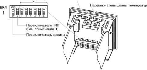
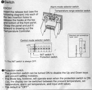
Термоконтроллер OMRON E5CSV является очень простым устройством в плане настройки. Разработчики отошли от классического параметрирования, и сделали все настройки с помощью переключателей. для доступа к этим переключателям необходимо вынуть переднюю панель из корпуса прибора.
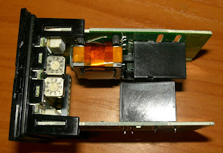 |
| Органы настройки E5CSV |
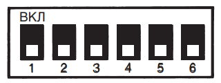
Внутри расположены один блок микропереключателей типа DIP и два многопозиционных переключателя.
 |
| Орагны настройки E5CSV |
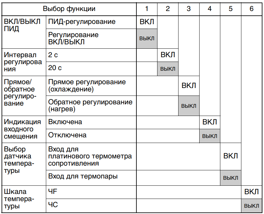
Блок микропереключателей предназначен для выбора режима работы регулятора.
 |
| Настроечные параметры E5CSV |
Назначение переключателей:
P — переключатель защиты (On — запрещено изменение задания, Off — доступны все функции)
X — не используется (должен быть всегда в Off)
1 — режим работы (On — ПИД регулятор, Off — двухпозиционный регулятор)
2 — период регулирования (On — 2 секунды, Off — 20 секунд)
3 — направление регулирования (On — прямое, Off — обратное)
4 — сдвиг входного сигнала (On — разрешен, Off — запрещен). Значение сдвига устанавливаентся параметром HO, на индикаторе.
5 — тип датчика (On — платиновый термометр сопротивления, Off — термопара)
6 — отображение температуры (On — градусы Фаренгейта, Off — градусы Цельсия)
Многопозиционный переключатель In служит для выбора исполнения датчика и диапазона измерения, согласно таблиц. Переключатель ALM устанавливает режим срабатывания сигнала тревоги. Выбирается опять же по таблице.
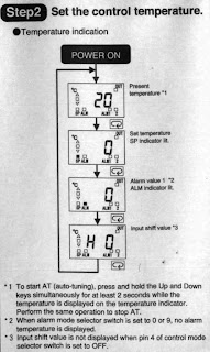 |
| Параметры, задаваемые на индикаторе прибора |
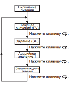
После установки данных параметров, необходимо задать на передней панели температуру задания (горит индикатор SP), пороги срабатывания тревог (горит индикатор ALM) и смещение входа. Перемещение между отдельными уставками выполняется кнопкой MODE.
 |
| Схема включения прибора |
В случае использования ПИД-регулирования, перед началом работы производится автоматическая настройка параметров. Для этого нажимаются и удерживаются более 2 секунд кнопки ВВЕРХ и ВНИЗ.
Больше никаких настроек в регуляторе OMRON E5CSV нет. Скан руководства на прибор можно найти здесь.
инструкцияOmron E5CSV

E5CSV/E5CS-U Digital Temperature Controller
Digital Temperature
Controller
E5CSVE5CSV
E5CS-UE5CS-U
E5CSVE5CSV
E5CS-UE5CS-U
E5CSVE5CSV
E5CS-UE5CS-U
User’s Manual
Cat. No. H140-E1-01
User’s ManualH140-E1-01
Overview
Preparations
Basic
Operations
Operations for
Applications
Parameters Appendices
Note: Specifications subject to change without notice.Cat. No. H140-E1-01
Authorized Distributor:
1005
OMRON Corporation
Industrial Automation CompanyControl Devices Division H.Q.Analog Controller Division
Shiokoji Horikawa, Shimogyo-ku,
Kyoto, 600-8530 Japan
Tel: (81)75-344-7080/Fax: (81)75-344-7189
Regional Headquarters
OMRON EUROPE B.V.
Wegalaan 67-69, NL-2132 JD Hoofddorp
The Netherlands
Tel: (31)2356-81-300/Fax: (31)2356-81-388
OMRON ELECTRONICS LLC
1 East Commerce Drive, Schaumburg, IL 60173
U.S.A.
Tel: (1)847-843-7900/Fax: (1)847-843-8568
OMRON ASIA PACIFIC PTE. LTD.
83 Clemenceau Avenue,
#11-01, UE Square,
239920 Singapore
Tel: (65)6835-3011/Fax: (65)6835-2711
OMRON (CHINA) CO., LTD.
Room 2211, Bank of China Tower,
200 Yin Cheng Road (M),
Shanghai, 200120 China
Tel: (86)21-5037-2222/Fax: (86)21-5037-2200
In the interest of product improvement, specifications are
subject to change without notice.
-
Страница 1
E5CSV/E5CS-U Digital T emperature Controller Digital T emperature Contr oller E5CSV E5CSV E5CS-U E5CS-U E5CSV E5CSV E5CS-U E5CS-U E5CSV E5CSV E5CS-U E5CS-U User’s Man ual Cat. No. H140-E1-01 User’s Manual H140-E1-01 Overview Preparations Basic Operations Operations f or Applications P arameters Appendices Note: Specifications subject to c[…]
-
Страница 2
Introduction OMRON products are manufactured f or use ac cordin g to proper proced ures by a qualif ied opera tor and only for the purpos es desc ribed in this manual. The E5CSV and E5C S-U are Compac t Digita l T emperature Controll ers. The E5CSV features screw ter minal c onnectio ns, and the E5C S-U features so cket pin connect ions. The main f[…]
-
Страница 3
Warranty and Limita tions of Liability WARRANTY OMRON’s ex clusive war ranty is that the pr oducts are fr ee from defects in mater ials and workmanship for a period of one year (or other period if s pecified) from date of s ale by OMRO N. OMRON MAKES NO WARRANT Y OR REPRESEN TATION , EXPRESS OR IMPLIED, REGARDING NON-INFRING EMENT, MERCHANTABI[…]
-
Страница 4
Disclaimers CHANGE IN SPECIFICATIONS Product spec ifications and ac cessor ies may be c hanged at any time based on improv ements and other reasons . It is our prac tice to change model numbers when published ratings or features are c hanged, or when significant cons truction changes are made. However, s ome specific ations of the products may be c[…]
-
Страница 5
Safety Precautions Definition of Precauti onary Information The following notat ion is us ed in this ma nual to provide pr ecauti ons re quire d to e nsur e safe usage of the product. The safety precautions that ar e provided are extremely impor tant to s afety . Alwa ys r ead and heed the information provided in all safety precautions. The follo w[…]
-
Страница 6
● Saf ety Precautions CA UTION Do not touch the terminals while pow er is being s upplied. Doing so may occasionally result in minor injury due to electric s hock. Do not allow pieces of metal, wire clippings , or fine metallic shavings or filings from installat ion to enter the product. Doing so may occasionally result in electric s hock, fire, […]
-
Страница 7
Precautions for Safe Use Be sure to obser ve the following precautions to prevent operation failur e, malfunction, or adv erse affects on the performance and func tions of the product. Not doing s o may occ asionally res ult in unexpected events. 1 ) The product is desig ned for indo or use only . Do not us e the prod uct outdoor s or in any of the[…]
-
Страница 8
13) A switch or circu it break er shou ld be prov ided cl ose to this Unit. The s witc h or circ uit breaker shoul d be within easy reac h of the operator, and must be mar ked as a dis connecting means for this unit. 14) Appro x imate ly 30 minutes is requ ired for the cor rect temperature to b e disp lay ed af ter tur ni ng the power supply t o th[…]
-
Страница 9
Installation Precautions Service Life Use the Temperatur e Controller within the following temperature and humidity ranges: Temperature: − 10 to 55 ° C ( with no icing or condens ation), Humidity: 25% to 85% If the Controller is ins talled inside a control boar d, the ambient temperature must be k ept to under 55 ° C, including the temperat[…]
-
Страница 10
Precautions for Operation 1 ) It takes approximately two seconds for the output s to turn ON from after the power supply is turned ON. Due consideration must be giv en to this time when incorpor ating Temperature Controllers into a c ontrol panel or similar devic e. 2 ) Make sure that the Temperature Controller has 30 minut es or more to warm up af[…]
-
Страница 11
Revision History A manual revision code appear s as a s uffix to the catalog number on the bac k cov er of the manual. Cat. No. H140-E1-01 The fol lowing tab le ou tlines the chan ges made to th e manu al dur ing each revis ion. Page n umbers refer t o the previous v ersion. Revision code Date Revised content 01 October 2005 Original produc tion x[…]
-
Страница 12
Conventions Used in This Manual Model Notat ions “E5CSV and E5CS- U” or “E5CSV/E5C S-U” ar e use d when th e informa tion b eing prov ided applies to all E5CSV and E5CS-U Digital Te mperature Controller s. Meanings of Abbrev iations The following abbreviations are used in parameter names, figures and in tex t explanations. T hese abbreviati[…]
-
Страница 13
About this Manual: Pur pose Relev ant s ection Details ● Overview Section 1 Over view Section 1 introduces the features, components, and main specifications of the E5CSV/E5CS-U Digital Temperature Controller s. ● Setup Section 2 Preparation Section 2 desc ribes the work required to prepare the E5CSV/E5CS-U Digital Temperature Controller s for o[…]
-
Страница 14
TABLE OF CONTENTS Introduction ……………………………………………………….. i Warranty and Li mitations of Lia bility …………………….. ii Safety Pr ecau tio ns …………………………………………… iv Precaut ions for S afe Use …………………………………… v i Installat ion Pr ec autions ..[…]
-
Страница 15
■ Changing th e SP …………………………………………………………………….. 3-7 3.6 Using ON/O FF Contr ol …………………………………………………………………………… 3-8 ■ ON/OFF Control ……………………………………………………………………… 3-8 3.7 Determ ining PID[…]
-
Страница 16
xv[…]
-
Страница 17
Section 1 Over vie w 1.1 Names of P ar ts ……………………………………………………….. 1-2 ■ F ront Panel …………………………………………………………1-2 ● E5CSV ……………………………………………………….. 1-2 ● E5CS-U ……………………………………………………[…]
-
Страница 18
Section 1 Over view Ov er view 1.1 Names of Parts ■ Front Panel ● E5CSV ● E5CS-U Lock Release Key Mode Ke y Mode indicat ors Deviation indicat ors T ool inser t ion hole Down K ey キ Alar m indic ators Up K ey Output indic ato r Mode indicat ors Mode Ke y Down K ey Up K ey Alar m indic ators Output indic ato r F ront doo r F ront door openin[…]
-
Страница 19
1.1 Names of Parts Ov er view ■ Using t he Keys This section desc ribes the bas ic func tions of the f ront panel k ey s. ● M (Mode) Ke y Press this key to change param eters within a setting level. ● U (Up) K ey Each press of this key increm ents the setting value. Holding the key down speeds up the increm entation. ● D (Down) K ey Each pr[…]
-
Страница 20
Section 1 Over view Ov er view 1.2 I/O Configurati on and Main Functions ■ I/ O Configur ation ● E5CSV and E5CS-U Control out p ut Alar m output 2 Alar m output 1 Alar m 1 func tion Alar m 2 func tion Control func tion Control section T emperature input * Functions can be assigned individually f or each output by changing the set values f or th[…]
-
Страница 21
1.2 I/O Configuration and Main Func tions Ov er view ● Control Outputs • • • A contro l output can be relay or voltage out put, depe nding on the model. ● Alarms Alar ms ar e suppor ted by E5CS V — @ 1 @@ — @ , E5CSV — @ 2 @@ — @ , E5CS- @ 1 @@ U- @ , and E5C S- @ 2 @@ U- @ . S et the alar m c lassificati on and alar m value or t he alar […]
-
Страница 22
Section 1 Over view Ov er view 1.3 Setting Level Configur ation and Key Ope rations P arameters are divided into groups, each called a “le vel . ” Ea ch of the s et v alues (setting items) in these lev els is c alled a “parameter . ”. The parameters on the E5CSV/E5CS-U ar e divided as follows: When the power is tur ned ON, “0” will be d[…]
-
Страница 23
1.3 Setting Level Configuration and Key O perations Ov er view ■ Selectin g Parameters • • • • • Within e ach lev el, th e parameter is c hang ed each tim e the M Key i s pressed. The parameter changes immediately after pressing the M key . M M M M Par ameter 4 Par ameter 3 Par ameter 2 Par ameter 1 ■ Fixi ng Settings If the M Ke y is[…]
-
Страница 24
Section 1 Over view 1-8 Ov er view 1.4 Setting Switches ● E5CSV Inser t the t ool ( refer to the diagram) into the two t ool ins er tio n holes (one on the top a nd one on the bottom) and r elease t he hooks. Then, grip the front panel and pull out towards you to remov e it. • Tool insertio n hole Tool inse rtion ho le Alarm mode switch *1 Temp[…]
-
Страница 25
1.4 Setting Switches Ov er view ON 1 2 3 4 5 6 ON INIT switch Protect switch P X Control mode swi tches Temperature ra nge switch Alarm mode s witch 0 4 3 2 1 5 9 8 7 6 0 4 3 2 1 5 9 8 7 6 ● Protect Switch • • • • • When the pr otect switch is ON, Up Ke y and Down Ke y operati ons are prohibited to prevent setting mistakes. The Mode Ke […]
-
Страница 26
Section 1 Over view Ov er view • Set the tem perature range us ing the temperat ure range switch numbers. Thermocouple input (E 5CSV — @ KJ, E5CS- @ KJU) Set rang e Speci- fica- tions Te m — per — ature range ° C ° F 0 0 to 200 0 to 200 1 0 to 300 0 to 300 2 0 to 400 0 to 400 3 0 to 500 0 to 500 4 0 to 600 0 to 600 K 5 0 to 999 0 to 999 6 0[…]
-
Страница 27
1.4 Setting Switches Ov er view Thermistor input ( E5CSV — @ G , E5CS- @ GU) Setting range Speci- fica- tions Te m — per — ature range ° C ° F 0 − 50 to 50 − 50 to 100 1 0 to 100 0 to 200 2 50 to 150 100 to 300 3 100 to 200 200 to 400 4 150 to 300 300 to 600 5 − 50 to 50 − 50 to 100 6 0 to 100 0 to 200 7 50 to 150 100 to 300 8 100 to […]
-
Страница 28
Section 1 Over view Ov er view ● Alarm Mode Switch • Sel ect the a lar m mode switch number w hen cha ngin g to the alar m mode. This switch is not provided in models without alar ms.) Set val u e Alarm type Alarm output operation 0,9 Alar m function OF F Output OFF 1 Upper- and lower-limit 2 Upper -limit 3 Lower-limit 4 Upper- and lower-limit […]
-
Страница 29
Section 2 Preparations 2.1 Insta llati on ……………………………………………………………………..2-2 ■ Exter n al Dimensio ns (Unit: mm) ……………………………2-2 ● E5CSV ………………………………………………………… 2-2 ● E5CS-U …………………………………………………[…]
-
Страница 30
Section 2 Preparations 2.1 Installation ■ External Di mensions (Unit: mm) 2-2 Prepar ations ● E5CSV 48 X 48 84 78 6 1.5 44.8 X 44.8 48 58 ● E5CS-U 48 X 48 94.45 (7.75) 6.25 72.5 14.2 58 44.8 X 44.8 48 ■ Panel Cutout Di mensions (Unit: mm) ● E5CSV and E5CS-U Individual Mounting Group Mounting 60 min. (48 × Num ber of Uni ts – 2.5) 45 45[…]
-
Страница 31
2.1 Installation Ada p te r Panel Waterproof pack ing Term inal co ve r Prepar ations • G roup mounting is pos sible in one direction only , either ver tic al or hor izontal. ■ Mounting For the Wiring Sock et, separately purchase the P2CF-08 or P3G-08 fo r models without alar ms, or the P2CF-11 or P3G A-11 f or models with alar ms. ● E5CSV ?[…]
-
Страница 32
Section 2 Preparations (1) Inser t the tool into the two tool inse r tion holes (one on the top and one on the bottom) and release the hook s. (2) Inser t the tool in the gap between the front panel and rear case , and pull out the front panel slightly . Grip the front panel and pull out fully . Be s ure not to impose excess ive f or ce on the pane[…]
-
Страница 33
2.2 Wiring Terminals 2.2 Wiring Terminals ■ Termin al Arrangement ● E5CSV ● E5CS-U (Without Alarms) . (With Alarms) * Purchase the P2CF-08 or P3G -08 wir ing sock et separately . * Purc hase the P2CF-11 or P3G A-11 wir ing sock et separately . 25 Prepar ations ① ② ③ ④ ⑤ ⑥ ⑦ ⑧ ⑨ ⑩ + − A B B Voltag e outp ut 12 VDC, 21 mA […]
-
Страница 34
Section 2 Preparations ■ Precautions wh en W i ri n g ・ Separate input leads and po wer lines in order to pre vent e xter nal noise. ・ Use A WG24 (cross-sectional area: 0.205 mm 2 ) to A WG18 (cross-s ectional area: 0.832 mm 2 ) twisted-pair cable (stripping length: 5 to 6 mm). ・ Use crimp ter m inals when wiring the ter m inals. ・ Tighte[…]
-
Страница 35
2.2 Wiring Terminals ● Control Outputs • • Outputs are s ent from t er minals 1 and 2 w ith the E5 CSV , a nd from termin als 4 to 6 with the E5CS -U . The f ollo wing di ag rams sh ow the av ailable outputs and their inter nal equaliz ing circuits. E5CS-U Rela y Voltage ④ ⑤ ⑥ GND ④ ⑤ ⑥ + — L + v E5CSV Rela y Vo ltage ① ② + v […]
-
Страница 36
Section 3 Basic Operations 3.1 Setting the Inp ut T ype …………………………………………………………. 3-2 ■ Input T ype ……………………………………………………….. 3-2 ● Ther mocouple ……………………………………………… 3-2 ● Platinum Resistance Ther mometer ………………….[…]
-
Страница 37
Section 3 Basic Operations 3.1 Setting the Input Type The E5CS is availab le in models with ther mo couple input, models with platinum resistance ther mometer input, ther mistor input, and multi-input (thermocouple/platinum resistance thermometer) models. The type of Sensor that can be us ed depends on the model. Confir m the model that was purchas[…]
-
Страница 38
3.1 Setting the Input Type Basic Operati ons Specifications Temper — ature range Input te mper ature range 6 K Ω (0 ° C) 0 -50 to 50 ( ° C) / -50 to 100 ( ° F) 6 K Ω (0 ° C) 1 0 to 100 ( ° C) / 0 to 200 ( ° F) 30 K Ω (0 ° C) 2 50 t o 150 ( ° C) / 100 to 300 ( ° F) 550 Ω (200 ° C) 3 100 to 200 ( ° C) / 200 to 400 ( ° F) 4 K Ω ([…]
-
Страница 39
Section 3 Basic Operations 3.2 Selecting the Temperature Unit ● T emperature Unit • • Select t he tem perature uni t as e ither ° C or ° F using the contr o l mode switch 6. The default is OFF ( ° C ). Basic Operati ons 3-4[…]
-
Страница 40
3.3 Selecting PID Control or O N/OFF Contr ol 3.3 Selecting PID Control or ON/OFF Control T wo control methods are supported: 2-PID control and ON/OFF control. Switching betw een 2-PID control and ON/OFF control is performed using the control mode switch 1. When this paramete r is set to ON, 2-PID control is selected, and when it i s set to OFF , O[…]
-
Страница 41
Section 3 Basic Operations 3.4 Setting Output Specifications ■ Control Per iod • • • • Set the out put per iod (contr ol per iod). Though a s hor ter per iod provides better contro l perfor mance, it is r ecommen ded that th e control peri od be set to 20 seconds or lon ger for a relay output to preser ve the ser vice l ife of the relay .[…]
-
Страница 42
3.5 Setting the Set Point (SP) 3.5 Setting the Set Point (SP) The operation lev el is display ed when the power is turned O N. When the M K ey is us ed to light the SP indicator in the dis play , the set point is displayed. ■ Changing the SP • T o change t he set po int, pre ss the U or D K ey while SP is li t on the display , and s et the desi[…]
-
Страница 43
Section 3 Basic Operations 3.6 Using ON/OFF Control In ON/OFF control, the control output turns OFF when the temperature being controlled reaches the preset set point. When the manipulated v ariable turns OFF , the temperature begins to f all and the control tur ns ON again. This operation is repeated o ve r a cer tain temperatur e range. At this t[…]
-
Страница 44
3.7 Determining PID Constants ( AT, ST, Manual Setup) 3.7 Determining PID Consta nts (A T, ST, Manual Setup) ■ AT (Auto-tuning) • • • When A T is executed, the optimum PID c onstants for the set po int at that time ar e set a utomat ically . A method (c alle d the limit c ycle method) for forcibly changing th e mani pulated var iable and fi[…]
-
Страница 45
Section 3 Basic Operations Basic Operati ons ■ ST (Self-tuning) ST (self-tuning) is a function that finds PID constants b y using step response tuning (SR T ) when Cont roller operation begins or when th e set point is changed. Once the PID constants ha ve been calculated, ST is not e xecuted when the ne xt control operation is star ted as long a[…]
-
Страница 46
3.7 Determining PID Constants ( AT, ST, Manual Setup) Basic Operati ons ● ST Stable Range Operatin g Procedure The ST s table range determines the set value under which ST (self-tuning) functions operate. This proc edure sets the ST stable range to 20 ° C. 1. Press the M K e y from the initial setting lev e l (1) and select “ST stable range”[…]
-
Страница 47
Section 3 Basic Operations Basic Operati ons ■ Manual Setup The manual settings f or PID constants are perf ormed separately in the “propor tional band” (P), “integral time” (I), and “der iv ativ e time” (D) parameters in the initial setting le vel (2). When PID constants are set manually , the tuning setting enab led in the initial s[…]
-
Страница 48
3.7 Determining PID Constants ( AT, ST, Manual Setup) Basic Operati ons • When P (Propor tional Band) Is Adjusted Incr eas- ing P The cur ve rises gr adually , and a long stabilization time is created, but o vershooting is prev ented. De- creas ing P Overshooting and hunting occur, but the set v alue is quickl y reached and the temperature stabil[…]
-
Страница 49
Section 3 Basic Operations 3.8 Alarm Outputs Alar ms c an be used w ith E5C S @ 1 @@ — @ (one alar m point) , E5C S @ 2 @@ — @ (two alar m p oints) , E5CS @ 1 @@ U- @ (one alar m point), and E5CS @ 2 @@ U- @ (two alar m points). Alar m output conditions ar e deter mined by a combinat ion of the “alar m type” and “alar m value”. • • T he[…]
-
Страница 50
3.8 Alarm Outputs Basic Operati ons 1. Set the alar m mode switch to 2 and then tur n ON the power . 2. Press the M K ey in the oper ation le vel and select the “alar m value 1” (ALM mode) parameter . 3. Use the U Ke y to s et the parameter to 10. Process value M SP mode ・ S et po i nt 0 2 1 2 ALM ALM SP OUT 0 1 2 ALM ALM SP OUT Power ON 0 1 […]
-
Страница 51
Section 3 Basic Operations 3.9 Shifting Input Values ■ Shifting Inputs When the control mode switch 4 is set to ON, the input shift value is display ed in the operation le vel and the shift can be added to the input. When the control mode s w itch 4 is set to OFF (no i nput shift display), the input shift is not dis pla yed b ut the shift value i[…]
-
Страница 52
3.9 Shifting Input Values Basic Operati ons ● Shift Method 1. Make sure tha t the control target temper ature (C) and Controller temperature (B) mat ch, with the control target temp erature near the set point. 2. Check the control target temperature (B) and the Controller readout (A). Subtract the Controller readout temperature (A) from the contr[…]
-
Страница 53
Section 4 Operations fo r Applications • • • 4.1 Movin g to the Initial Setting Le vel ………………………………. 4-2 4.2 Assigning Outputs …………………………………………………… 4-3 ■ Output A ssign ment …………………………………………….. 4-3 4.3 Alar m Functions …………………….[…]
-
Страница 54
Section 4 Oper ations fo r Applications 4.1 Moving to the Initial Setting Level • T o move to the initial setting le vel, turn OFF the protect s w itch, turn ON the INIT swit ch, and then hold down the U Ke y w hile tur ning ON the power . T he status of the c ontrol mode switches 1 to 6 is ignored. 1. From the initial setting lev el selection di[…]
-
Страница 55
4.2 A ssigning Output s 4.2 Assigning Outputs • • • By cha nging th e co ntrol out put ass ignment, alar m output 1 assignment, and alar m output 2 assignm ent settings, the func tions assigne d to each ou tput c an be chang ed in t he init ial setti ng level (3). The follo wing functions c an be assigned to each output. ■ Output Assignment[…]
-
Страница 56
Section 4 Oper ations fo r Applications 4.3 Alarm Functions • ■ Alar m Hysteresis • • • • • • The hysteresis of alar m o utputs wh en alar ms are switched O N/OFF can be set as follows: Alar m hysteresis is alwa ys 0.2 ( ° C or ° F). ■ Standby Sequence The sta ndby sequence ca n be us ed so th at an alar m will not be output unt[…]
-
Страница 57
Operati ons f or Applications 4.3 Alarm Functions ■ Close in Alarm/Open in Alarm • • • • When “ close in alar m” is set, the status o f the a lar m fu nction wi ll be output as is. When “open in alar m” is set, the s tatus of the alar m function will be reversed bef ore being output. Close in alar m/open in alar m can be s et sepa[…]
-
Страница 58
Section 4 Oper ations fo r Applications 4.4 Setting the SP Upper and Lower Limit Values • ■ Set Point Limiter The setting range of the set point i s limited by the set point limiter . The set point limiter is used to pre vent the control target from reaching abnor mal temperatures. The upper- and lowe r-limit values o f the set point limiter ar[…]
-
Страница 59
Operati ons f or Applications 4.4 Setting the SP Upper and Lower Limit V a lues • • • Setting the S et P oint Upper-l imit V alue Operatin g Procedure Set P oint Upper Limit = 1000 1. Press the M K ey from the initial setting le vel (3) and select “set point upper limit” (SP mode). 2. Use the U and D K e ys to s et 1000. Setting the Set P[…]
-
Страница 60
Section 4 Oper ations fo r Applications 4.5 Alarm Delays • ■ Alarm Delays • • • Delays can be set for the alar m out puts. ON an d OFF delays can b e set separate ly for alar ms 1 a nd 2. The ON and OFF de lays f or alar ms 1 and 2 also apply to the individ ual ALM 1 and ALM2 indicator s. The a lar m ON d elays will also func tion w hen t[…]
-
Страница 61
Operati ons f or Applications 4.5 Alar m Delays ● Parameter s Relate d to Alarm Delays P aramete r name Setting Set (monitor ) values Alar m 1 ON Delay Initial setting lev el (4) SP mode 0 to 999 (s) Alar m 2 ON Delay Initial setting lev el (5) SP mode 0 to 999 (s) Alar m 1 OFF Delay Initial setting lev el (4) ALM mode 0 to 999 (s) Alar m 2 OFF D[…]
-
Страница 62
Section 4 Oper ations fo r Applications Operati ons f or Applications 4-10[…]
-
Страница 63
Section 5 P arameter s 5.1 Conv entio ns Used in this Section …………………………………………. 5-2 ● Meanin gs of Icons Used in thi s Sec tion ………….. 5-2 ● About R elated P arameter Displ a ys ………………… 5-2 ● The Order in Which P arameters Are Descr ibed i n T his Sectio n ……………………………[…]
-
Страница 64
Section 5 Param eters 5.1 Conventions Used in this Section ● Meanings of Icons U sed in this Section Descr ibes the functions of the parameter . Descr ibes the setting range and default of the parameter . ● About Related Parameter Displa ys P arameters are displa yed only when the conditions of use indicated for the p arameter are satisf ied. I[…]
-
Страница 65
5.2 Operation Level 5.2 Operation Level Displa y this le vel to perf or m standard control operations. The set points and alarm values are set in this lev el. M M M M Process v alue SP mode ・ Set point ALM mode ・ A larm val ue 1 A LM 2 mode *1 ・ A larm val ue 2 5-4 5-4 5-4 5-5 Page 0 2 1 2 AL M AL M SP OUT 0 1 2 AL M AL M SP OU T 0 1 2 AL M A[…]
-
Страница 66
Section 5 Param eters P a rameters Process v alue Displays the proces s value (except when no PV display is selected) * The dec imal position is s et automatically by the selected Sens or . Monitor range Unit Process value Input indication range (See pages A-12 and A- 13.) EU • Function SP mode Set point • Dis plays the set point. * The decimal[…]
-
Страница 67
5.2 Operation Level ALM2 mode Alarm v alue 2 This parameter is s et to the input values “X” or “Y” in the alar m type lis t. The ALM will flash in the dis play while the alarm value 2 is dis play ed. • T his parameter sets the alar m value f or alar m output 2. * The decimal position is s et automatically by the selected Sens or . Alarm t[…]
-
Страница 68
Section 5 Param eters P a rameters IS mode (1) Manual r eset v alue h / l • • This function r esets the offs et that occurs when P (or PD) c ontrol is used. The offse t that occ urs is s et in ° C or ° F as the manual r ese t value. (This applies when manual reset is enabled.) This parame ter is disp lay ed on ly when c ontrol mode switch 4 i[…]
-
Страница 69
5.2 Operation Level IS mode (3) Alarm 1 latch status a1 • • • This parameter displays the alar m 1 latc h status. The latch ca n be clear ed by pressing the U and D K eys for at least 2 s while the alar m 1 latch status is displayed. The alar m 1 l atch status i s only dis play ed when l atch O N (1) is set in the “alar m 1 latch” paramet[…]
-
Страница 70
Section 5 Param eters 5.3 Moving to the Initial Setting Level The initial setting lev el is used to mak e the settings that maximize T emperature Controller perfo r mance. Control stops when moving to the initial setting lev el. The methods f or moving to the initial setting lev el are desc ribed her e. Power ON Initial se tting le v el — 0 — 1 2 A[…]
-
Страница 71
5.4 Initial Setting Leve l (1) 5.4 Initial Setting Level (1) Mov e to initial setting lev el (1) by selecting “ 1” in the initial setting lev el selection disp la y and pressing the M Ke y . This lev el is used to set the follo wing parameters including tuning, hysteresis for ON/OFF c ontrol. In the initial setting level (1), the ▲▼ deviati[…]
-
Страница 72
Section 5 Param eters P a rameters SP mode PV auto reset PV/SP displa y T uning selection ST e x ecuting displa y Manual r eset enabl e/disabl e Control period selection Set whether to enable or disab le PV auto reset. Set the PV/SP display . Select the tuning method. Set whether to enable or disab le the ST ex ecution display . Set whether to enab[…]
-
Страница 73
5.4 Initial Setting Leve l (1) 100’ s digit 10’ s di git 1’ s digit Di sp laye d num ber PV auto reset PV/SP display T uning selection ST ex ecution display Manua l reset enable/ disable Contr ol period selection 0 Disabled ST / AT 2 / 20 1 Enabled ST Disabled 6 / 60 2 PV → SP AT 2 / 20 3 ST / AT Enabled Enabled 6 / 60 4 ST 2 / 20 5 SP → […]
-
Страница 74
Section 5 Param eters P a rameters ALM mod e Integr al time setting unit Hysteresis width T emperatur e width in whic h the ■ de viation indicator li ghts • • • Select the integral time setting unit. Set the hysteresis width. Set the temperature width in which the ■ deviation indicator lights. • • • Set the integral t ime sett ing u[…]
-
Страница 75
5.4 Initial Setting Leve l (1) IS mode ST stabl e range • T he setting of this parameter deter mines when ST operates. Setting range Unit Default 1 to 999 ° C/ ° F 15 Function Setting P a rameters 5-13[…]
-
Страница 76
Section 5 Param eters 5.5 Initial Setting Level (2) Mov e to initial setting le v el (2) by selecting “2” in the initial setting lev el selection displa y and pressing the M Ke y . Manual PID settings can be set in this lev el. In the initial setting lev el (2), the ▲ ■ ▼ deviation indicators are lit. Initial se tting level (2 ) Page 5-15[…]
-
Страница 77
5.5 Initial Setting Level (2) SP mode Propor tional band The propor tional band (P) is set in this parameter . The propor tional band f or A T (auto-tuning) and ST (self- tuning) can also be s et automatically . P operation: Ref ers to contr ol in w hich the MV is pr opor tional to the deviation. Setting range Unit Default 1 to 999 ° C/ ° F 8 * W[…]
-
Страница 78
Section 5 Param eters 5.6 Initial Setting Level (3) Mov e to initial setting le v el (3) by selecting “3” in the initial setting lev el selection displa y and pressing the M Ke y . The set point upper- /lower-limit values and output assignment can be set in this lev el. In the initial setting lev el (3), the ▲ deviation indicator is lit. M M […]
-
Страница 79
5.6 Initial Setting Level (3) SP mode SP upper lim it • • • This parameter sets the u pper li mit of the set po int. T he set poi nt can be set within the range with the u pper limit set in the “S P upper lim it” par ameter. If this para meter is res et, howev er , any set poin t that is outs ide of the n ew range will be forcib ly change[…]
-
Страница 80
Section 5 Param eters P a rameters IS mode (1) Control output assignm ent ot • T his parameter sets the function to be assigned to the c ontrol output. Displa yed numb er Set v alue Setting r ange Default 0 No assignment 1 Control func tion 2 Alar m 1 function 3 Alar m 2 function 0 to 3 1: Control func tion Function Setting IS mode (2) Alarm 1 as[…]
-
Страница 81
5.6 Initial Setting Level (3) IS mode (3) Alarm 2 assignment a2 • T his parameter sets the function to be assigned to alar m output 2. Displa yed numb er Set v alue Setting range Default 0 No assignment 1 Control function 2 Alar m 1 func tion 3 Alar m 2 func tion 0 to 3 3: Alar m 2 func tion * Not displayed f or models without alar m output 2. Fu[…]
-
Страница 82
Section 5 Param eters 5.7 Initial Setting Level (4) Mov e to initial setting le v el (4) by selecting “4” in the initial setting lev el selection displa y and pressing the M Ke y . The settings r elated to the alar m 1 ON/OF F delay and alarm 1 c an be set in this level. In the initial setting lev el (4), the ▲ ■ deviation indicators are li[…]
-
Страница 83
5.7 Initial Setting Level (4) SP mode Alarm 1 ON dela y Alar m 1 function is preven ted from tur ning ON until after the delay time set in this parameter has elapsed. Set the time for which the ON delay is to be enab led. T o disable the ON delay , set 0. P arameter Setting range Unit Default Alar m 1 ON delay 0 to 999 Second 0 * This parameter is […]
-
Страница 84
Section 5 Param eters P a rameters IS mode (1) Alarm 1 type al • • Select one of the follo wing nine alar m 1 types : This parame ter is disp lay ed only for mode ls witho ut alar m outputs ( i.e., models wit hout an alar m mode switch). Se ttings for models with alar m outputs are set us ing the alar m mode switch. Set val u e Alarm type Alarm[…]
-
Страница 85
5.7 Initial Setting Level (4) IS mode (2) Alarm 1 open in alar m nc • • This parameter sets the output status for alar m 1. When “c lose in a lar m” is se t, the sta tus of the a lar m 1 function w ill be outp ut as is. When “ope n in alar m ” is set, the status of the alar m 1 function will be rev ersed before being output. P aramete r[…]
-
Страница 86
Section 5 Param eters 5.8 Initial Setting Level (5) Mov e to initial setting le v el (5) by selecting “5” in the initial setting lev el selection displa y and pressing the M Ke y . The settings r elated to the alar m 2 ON/OF F delay and alarm 2 c an be set in this level. In the initial setting lev el (5), the ▼ deviation indicator is lit. M 0[…]
-
Страница 87
5.8 Initial Setting Level (5) SP mode Alarm 2 ON dela y Alar m 2 function is preven ted from tur ning ON until after the delay time set in this parameter has elapsed. • • Set the time for which the ON delay is to be enab led. T o disable the ON delay , set 0. P aramet er Setting range Unit Default Alar m 2 ON delay 0 to 999 Second 0 * This para[…]
-
Страница 88
Section 5 Param eters P a rameters IS mode (1) Alarm 2 type al • Selec t one of the follo wing nine alar m 2 types : Set val u e Alarm type Alarm output operation 0 Alar m function OFF Output OFF 1 Upper- and lower-limit 2 Upper-limit 3 Lower-limit 4 Upper- and lower-limit range 5 Upper- and lowe r-limit with standby sequence 6 Upper-limit with s[…]
-
Страница 89
5.8 Initial Setting Level (5) IS mode (2) Alarm 2 open in alar m nc • • This parameter sets the output status for alar m 2. When “c lose in a lar m” is se t, the sta tus of the a lar m 2 function w ill be outp ut as is. When “ope n in alar m ” is set, the status of the alar m 2 function will be rev ersed before being output. P aramet er[…]
-
Страница 90
Appendices Specifications ………………………………………………………………. A -2 ■ Ratings …………………………………………………………………. A-2 ■ Characteristic s ………………………………………………………. A-3 Error Display s ……………………………………….[…]
-
Страница 91
Appendices Specifications ■ Ratings Supply voltage 100 to 240 V AC , 50/60 Hz 24 V AC , 50/60 Hz/24 VDC Oper ati ng vol tag e range 85 to 110% of rated supply v oltage Power consumption 5 V A 3 V A/2 W Sensor input *1 Thermocouple input type: K, J, L Platinum resistance thermometer input type: Pt100, JPt100 Thermistor : E52-THE @@ Multi- input (t[…]
-
Страница 92
Specifications Appendices ■ Characteristics Indication accuracy (ambient temper ature of 23°C) Thermocouple: *1 (±0. 5% o f indic ation value or ±1°C, whichev er is grea ter) ± 1 di git max. (E5CSV) (±1. 0% o f indic ation value or ±2°C, whichev er is grea ter) ±1 digit max . (E5CS-U) Platin um res istanc e thermo meter: *2 ( ± 0.5% o f[…]
-
Страница 93
Appendices Error Displays When an error oc curs, the error contents are s hown on the display window . This sec tion descr ibes how to check error c odes on the display , and the actions to be taken to remedy the problems. Ov erflow ● Meaning (1) The process value is higher than the control temperature range. (2) T he Sensor has s hor ted when us[…]
-
Страница 94
Error Disp lays Appendices Flashing Input Sensor Error (High T emperatur e) ● Meaning (1) The pr ocess value is hig her than the overflo w temperature or a sensor error has occurred when using a ther mocouple input or platinum resistance ther mometer input model. (2) The process value is higher than the control temper ature range or a sensor erro[…]
-
Страница 95
Appendices Appendices Displa y Range Exceeded ● Meaning This does not indicate an error . It is displa yed if the process v alue ex ceeds the display rang e when the control range is larger than the display range. • • When less than − 99 : [[[ When more than 1999 : ]]] ● Operation Control continues, allowi ng nor mal operation. This displ[…]
-
Страница 96
Burnout/Short-c ircuit Display and Causes Burnout/Shor t-cir cuit Displa y and Causes The display window shows the error details if an input s ensor burnout or shor t- circuit oc curs. The error display and control output operation f or burnouts and shor t-circuits is e xplained below for each input type. ● Thermocouple Status Display Contr ol ou[…]
-
Страница 97
Appendices Parameter Operation Lists ■ Operation Level Par a m et er s Mode indicators/ displayed text Setting (m onitor) valu e Default Unit Set val ue Process value − Sensor input indicat ion range EU Set point SP mode SP lower limit t o SP upper li mit 0 EU Alar m value 1 ALM mode 1 to 7: 0 to input setti ng range full scal e 8: Input settin[…]
-
Страница 98
Parameter Oper ation Lists Appendices ■ Initial Setting Level (1) P aramete rs Mode indicators/ displayed text Setting (monitor ) value Default Unit Set val ue 0: No PV auto reset SP mode 100’ s digit 1: Y es 0 None PV/SP displa y T uning selection 0 ST/A T 1 ST 2 PV → SP AT 3 ST/A T 4 ST 5 SP → PV AT 6 ST/A T 7 ST 8 No PV display AT PV/SP […]
-
Страница 99
Appendices Appendices ■ Initial Setting Level (2) Par am e t e rs Mode indic ators /disp lay ed text Setting (monitor) value Default Unit Set val ue Propor tional band SP mode 1 to 999 8 °C/°F 0 to 1999 233 Second Integ ral time ALM mode 0 to 99 4 Minute Deriv ative tim e IS mode 0 to 1999 40 Second ■ Initial Setting Level (3) Par am e t e rs[…]
-
Страница 100
Parameter Oper ation Lists Appendices ■ Initial Setting Level (4) Par am e t e rs Mode indic ators /disp lay ed text Setting (monitor) value Default Unit Set val ue Alarm 1 ON delay SP mode 0 to 999 0 Second Alarm 1 OFF delay ALM mode 0 to 999 0 Second 0, 9: N o alar m 1: Upper-/low er-limit 2: Upper limit 3: Low er limit 4: Upper-/low er-limit r[…]
-
Страница 101
Appendices Sensor Input Setting Range, Indication Range, Control Range Input type Specifica- tions T emperature range Input temperatur e range Control rang e 0 0 to 200 ( ° C)/0 to 200 ( ° F) − 20 to 220 ( ° C)/ − 20 to 220 ( ° F) 1 0 to 300 ( ° C)/0 to 300 ( ° F) − 30 to 330 ( ° C)/ − 30 to 330 ( ° F) 2 0 to 400 ( ° C)/0 to 400 ( […]
-
Страница 102
Sensor Input Setting Range, Indication Range, Contr ol Range Appendices Input type Specifica- tions T emperature range Input temperatur e range Control rang e 0 − 99 to 850 ( ° C)/ − 99 to 1,500 ( ° F) − 119 to 870 ( ° C)/ − 139 to 1,540 ( ° F) 1 0.0 to 199.9 ( ° C)/0.0 to 199.9 ( ° F) − 20.0 to 219.9 ( ° C)/ − 40.0 to 239.9 ( °[…]
-
Страница 103
Setting Lev e ls Diagram Setting Levels Diagram This diagram show s all of the setting le vel s. Some parameters are not displ ay ed depending on the protect lev el setting and the c onditions of use. Control is st opped for each of the initial setting lev els. Operat ion level Power ON * : INIT swit ch: ON : Protect switc h: OFF U Key — 0 — 1 […]
-
Страница 104
Param eter Flow Parameter Flow This section descr ibes the parameters set in each le vel. Pressing the M ke y at the las t parameter in each lev el retur ns to the top parameter in that level. Initial sett ing le v el (2) Initial sett ing lev el (1) Initial sett in g lev el No ke y in p ut for 5 s or l on g er Po w e r O N SP mode PV auto reset PV/[…]
-
Страница 105
Pa r a m e t e r F l o w Appendices Initial setting (5) SP mode Alarm 2 ON dela y (0: Disab led, 1 to 999 s) ALM mode Alarm 2 OFF dela y (0: Disab led, 1 to 999 s) IS mode (1) Alarm 2 type (0 to
 IS mode (2) Alarm 2 open in alarm (0: Closed in alarm; 1: Open in alarm) IS mode (3) Alarm 2 latch (0: OFF; 1: ON) M M M M M 0 c n 1 2 AL M AL M SP OU T[…]
 -
Страница 106
Index Index 2 2-PID control……………………………………………………………3-5 A alar m 1 ass i gnment…………………………………………………. 5-18 alarm 1 latch …………………………………………………………..5-23 alarm 1 OFF delay…………………………………………………..[…]
-
Страница 107
Index Appendices initial setti ng le vel (1)……………………………………….. A-9, 5-9 initial setti ng le vel (2)……………………………………. A-10, 5-14 initial setti ng le vel (3)……………………………………. A-10, 5-16 initial setti ng le vel (4)……………………………………. A-11, 5-20 ini[…]
-
Страница 108
Index protect switc h ……………………………………………………….1-9 tempera ture range switc h ……………………………………..1-10 setting t he SP upper a nd lo wer li mit va lues ………………….. 4-6 shift metho d…………………………………………………………… 3-17 shifting inp ut val[…]
 IS mode (2) Alarm 2 open in alarm (0: Closed in alarm; 1: Open in alarm) IS mode (3) Alarm 2 latch (0: OFF; 1: ON) M M M M M 0 c n 1 2 AL M AL M SP OU T[…]