Video Snake 3588 Система видеоинспекции труб и стен Руководство пользователя
ПРЕДУПРЕЖДЕНИЕ
- НИКОГДА НЕ ИСПОЛЬЗУЙТЕ ЭТО УСТРОЙСТВО В СРЕДЕ С ВЗРЫВООПАСНЫМИ МАТЕРИАЛАМИ, ТАКИМ КАК ГАЗ, МАСЛО И Т.Д.
- Избегайте использования устройства в очень холодных, жарких или влажных условиях; в противном случае это может привести к повреждению устройства. Не роняйте и не нажимайте сильно на устройство.
- Избегайте использования в этой системе деталей/компонентов других производителей, которые могут повредить оборудование из-за несовместимости.
- Аннулирование гарантии в случае разборки устройства пользователем или наличия физических повреждений.
- Всегда делайте резервную копию своих данных перед подключением USB-накопителя/карты micro SD к этой системе. Производитель не несет ответственности за повреждение или потерю данных на USB-накопителе / карте памяти micro SD по любой причине.
- Не отключайте устройство во время записи или воспроизведения. Это может привести к повреждению устройства и/или USB-накопителя/карты Micro SD.
- Не злоупотребляйте кабелем зарядного устройства и шнуром питания, иначе аккумулятор может быть поврежден или система не будет работать должным образом.
- Нажимной трос системы из стекловолокна очень жесткий и не гибкий. Его нельзя резко сгибать или слишком сильно нажимать; иначе он будет сломан.
- Водонепроницаемая головка камеры НЕ должна использоваться под водой на глубине более 15 футов.
- Мы оставляем за собой право вносить любые изменения в наши продукты без предварительного уведомления.
ОТКАЗ ОТ ОТВЕТСТВЕННОСТИ
Forbest Products Co. НЕ НЕСЕТ ОТВЕТСТВЕННОСТИ ПЕРЕД ДИСТРИБЬЮТОРОМ, ТОРГОВЫМ ТОРГОВЫМ ИЛИ ЛЮБЫМ ДРУГИМИ ЛИЦАМИ ЗА ЛЮБЫЕ СЛУЧАЙНЫЕ, НЕПРЯМЫЕ, ОСОБЫЕ, ПРИМЕРНЫЕ ИЛИ КОСВЕННЫЕ УБЫТКИ ИЛИ ТРАВМЫ ЛЮБОГО ТИПА, ВЫЗВАННЫЕ НАПРЯМУЮ ИЛИ КОСВЕННО ПРОДУКТАМИ, ПРОДАВАЕМЫМИ ИЛИ ПОСТАВЛЯЕМЫМИ Forbest Products Ко..
Сборочный чертеж и список деталей
|
Номер |
Описание |
|
1 |
|
|
2 |
|
| 3 |
|
|
4 |
зарядное устройство |
| 5 | Чехол для батареи |
| 6 | Большой кейс □Корпус из АБС-пластика |
| 7 | DC 12V питания |
| 8 | Щит от солнца |
| 9 | Защита мяча Eva |
| 10 | Мягкий видеокабель 3 м (короткий) |
| 11 | дистанционное управление |
| 12 | Диск |
| 13 | Сумка для предохранителей |
Характеристики
| ПУНКТ | ОПИСАНИЕ |
|
Адаптер питания |
110В~240В~ 12В=1200мА |
| Корпус батареи |
Литий-ионный аккумулятор |
|
Длина кабеля |
Диаметр 8мм □45м □65м |
| Источник света камеры |
□12шт□18шт встроенный белый светодиод |
|
Угол обзора камерыView |
60° или 90° (по горизонтали),
60° или 90° (по вертикали) |
| Глубина камерыView |
200-400 мм (приблизительно) |
|
Изображение камеры |
Цвет, 0.3 мегапикселя |
| Изображение монитора |
7-дюймовый/10-дюймовый цветной ЖК-монитор TFT |
|
Разрешение изображения монитора |
800 * 480/800 * 600 пикселей |
| Входной объем монитораtage |
12 Volts DC |
|
Рабочая температура системы |
-28 50 ° C до ° C |
Заявление
- СИСТЕМА ВОДОСНАБЖЕНИЯ
- СИСТЕМА СТОЧНЫХ ВОД
- ЭЛЕКТРИЧЕСКИЙ КОНДИЦИОНЕР ВОЗДУХА
- КАБЕЛЬНЫЕ ПРОВОДЫ
- КАНАЛЬНЫЕ ВАКУУМНЫЕ СИСТЕМЫ
- САНТЕХНИКА
- ЗДАНИЯ
ПРЕДУПРЕЖДЕНИЕ: НИКОГДА НЕ ИСПОЛЬЗУЙТЕ ЭТО УСТРОЙСТВО В СРЕДЕ С ВЗРЫВООПАСНЫМИ МАТЕРИАЛАМИ, ТАКИМ КАК ГАЗ, МАСЛО И Т.Д.
Знай свое устройство
ЗАПИСЬ НА DVR ЧЕРЕЗ USB-ПОРТ:
- КНОПКА ВЫБОРА ВИДЕО
- МЕНЮ
- ВНИЗ (ЗЕРКАЛЬНОЕ ИЗОБРАЖЕНИЕ ВВЕРХ ИЛИ ВНИЗ)
- ВВЕРХ (ЛЕВОЕ ИЛИ ПРАВОЕ ЗЕРКАЛЬНОЕ ИЗОБРАЖЕНИЕ)
- МЕНЮ ПЕРЕКЛЮЧАТЕЛЬ ВВЕРХ/ВНИЗ/16:9 ИЛИ 4:3
- Светодиод ВКЛ / ВЫКЛ
- КНОПКА ПИТАНИЯ
- ПЛОСКИЙ ЭКРАН
- DC 12 В В
- ВИДЕО ВЫХОД
- ПОРТ КАМЕРЫ
- USB
- КНОПКА ПИТАНИЯ И ЗАРЯДКИ
- ЗАРЯДНЫЙ ПОРТ
- ВЫХОДНОЙ ШНУР 12 В ПОСТОЯННОГО ТОКА
- ЗОНА
- микрофон
- ВКЛ/ВЫКЛ видеорегистратор
- ЗАПИСЬ
- СТОП/ВЫХОД
- УСТАНОВКА
- UP
- DOWN
- PLAY/ENT 25. ВКЛ/ВЫКЛ МИКРОФОН
ЗАПИСЬ ЧЕРЕЗ MICRO SD PORT:
- ПЛОСКИЙ ЭКРАН
- DC 12 В В
- ВИДЕО ВЫХОД
- ПОРТ КАМЕРЫ
- ПОРТ ICRO SD (ТОЛЬКО ДЛЯ НОВЫХ ВЕРСИЙ)
- КНОПКА ПИТАНИЯ И ЗАРЯДКИ
- ЗАРЯДНЫЙ ПОРТ
- ВЫХОДНОЙ ШНУР 12 В ПОСТОЯННОГО ТОКА
- ЗОНА
- микрофон
- ЗАПИСЬ/СЪЕМКА
- ENTER
- МЕНЮ / ВЫХОД
- ЛЕВЫЙ
- ПРАВО
- МИКРОФОН ВКЛ. / ВЫКЛ.
Головка камеры
- 12 БЕЛЫХ светодиодов (18 для большой камеры)
- ОБЪЕКТИВ
- ВЕСНА
- ЗОЛОТЫЕ БУЛАВКИ
Встроенный передатчик: 512 Гц
Кабельный барабан
Кабель с микроэлектронным счетчиком
- Штекер (для мониторинга)
- BODY КАДР
- КАБЕЛЬНАЯ КАТУШКА
- м/фут
- СБРОС
- РАЗЪЕМ (В камеру
Дистанционное управление (управление DVR/запись на карту Micro SD)
- Введите: Войдите в view и воспроизвести видео
- До: Перейти к предыдущему элементу
- UP: выбрать вверх/последний элемент
- РЕК: Начать запись / моментальную съемку
- Настроить: Настройка системы и функции записи
- ВКЛЮЧЕНИЕ / ВЫКЛЮЧЕНИЕ ПИТАНИЯ
- Вниз: Выбрать вниз/следующий элемент
- Выход: Остановить или выйти из текущего меню
- Слева: Выбрать левый элемент
- Справа: Выберите правильный элемент
- Перемотка назад: Review видео
- Вперед: переслать видео
Настройка системы
- ВАЖНО: При подключении камеры к монитору питание должно быть отключено, иначе оба устройства могут быть повреждены.
- Прикрутите камеру к кабелю катушки (см. рис. 1-A) и соедините катушку с монитором (см. рис. 1-B).
- Вставьте предохранитель в гнездо, расположенное сбоку батарейного отсека.
- Вставьте шнур адаптера питания в настенную розетку переменного тока, а другой конец — во входное гнездо постоянного тока 12 В на мониторе (если настенный адаптер входит в комплект поставки вашего устройства и см. Рисунок 1-C); если вы решите использовать заряженную батарею, подключите шнур питания батареи к входному разъему постоянного тока 12 В на мониторе, затем нажмите кнопку на батарее. Пользователь также может заряжать аккумулятор во время использования устройства следующим образом: подключите зарядное устройство к настенной розетке переменного тока, а другой конец к разъему на аккумуляторе и подключите выходной шнур аккумулятора к входу постоянного тока 12 В. Разъем монитора, затем нажмите кнопку батареи.
Примечание: Не злоупотребляйте шнуром питания и кабелем зарядного устройства, в противном случае система может работать неправильно или аккумулятор может быть поврежден. - Нажмите МОЩНОСТЬ кнопку на передней панели монитора. Огни станут зелеными.
- Аккуратно опустите камеру в канал трубы и т. д. и намотайте кабель, пока он не окажется на нужной глубине.
- Нажмите LED кнопку и отрегулируйте яркость в МЕНЮ.
- Запишите изображения, если это необходимо для моделей с цифровым видеорегистратором (см. операцию записи).
- С помощью видеокабеля вы можете перенести изображение на другой экран большего размера.
- По окончании работы осторожно снимите камеру с патрубка и т. д. Вывинтите головку камеры и протрите ее чистой, мягкой и сухой тканью, после чего установите камеру в прежнее положение.
|
Настройка часов: установить дату и время |
|
| Формат времени | Выберите: 24 часа – 12 часов |
| Год | Установить год |
| Месяц | Установить месяц |
| день | Установить день |
| час | Установить час |
| Минута | Установить минуты |
| Во-вторых, | Установить секунды |
| Настройка языка | Выберите: английский – китайский |
| Система: показывает версию программного обеспечения, версию продукта, свободное и используемое пространство (при подключении USB/micro SD) | |
| Настройка записи: выбор устройства хранения — USB-накопитель или микро SD | |
| Режим воспроизведения: нет круга, один круг, список кругов | |
| Общий сброс: снова нажмите OK, чтобы выполнить общий сброс. | |
| Обновление прошивки: найдите каталог, в котором хранится новая прошивка | |
| Приложения File: показаны все files на текущем носителе USB/Micro SD. | |
| Удалить устройство USB/micro SD (только при подключении устройства USB/Micro SD) Всегда используйте этот параметр перед безопасным извлечением устройства USB/micro SD из порта USB/micro SD |
Запись Операция
- Установите кнопку «Экран видео» на видео 2.
- Снимите изоляционную пленку с батареи пульта дистанционного управления.
- Нажмите кнопку дистанционного управления 5
войти в систему записи; вы можете увидеть систему DVR / устройство записи карт памяти micro SD ВИДЕО меню на экране.
- Вставьте USB-накопитель/съемный жесткий диск в USB Порт или карта micro SD в слот для карты micro SD, вы можете видеть USB-палки / микро SD-карта подключена на экране и горит светодиодный индикатор. 7
Примечание: Когда вы подключаете USB-накопитель/карту micro SD перед запуском устройства, возможно, устройство не может найти USB-накопитель/карту micro SD. В этом случае удалите их и повторите попытку. - Нажмите кнопку дистанционного управления 3
чтобы начать запись, и загорится индикатор RECORDING. Во время записи снова нажмите кнопку RECORDING, видеорегистратор сделает снимок, и он будет сохранен на USB-накопителе или карте памяти micro SD (функция моментальной съемки доступна только для новых версий).
- Нажмите кнопку дистанционного управления 7
остановить запись.
- Нажмите кнопку дистанционного управления 1
повторноview запись.
- Если вам нужно управлять своими записываемыми изображениями, нажмите кнопку 4 на пульте дистанционного управления.
. Вы также можете управлять видео files, выбрав НАСТРОЙКИ on ВИДЕО руководство на экране.
ПРИМЕЧАНИЕ:
Системе DVR иногда требуется 10-20 секунд для изменения положения, прежде чем она сможет работать должным образом, пожалуйста, дайте ей поработать около 20 секунд каждый раз, когда вы пытаетесь записать.
Максимальный объем памяти USB-накопителя и микро SD составляет 8 ГБ.
Светодиодные индикаторы
- REM : Окно удаленного приема
- Питание: указывает, что система включена.
- Запись: он будет мигать во время записи
- USB/Micro SD: указывает на то, что устройство USB/micro SD подключено
- Ошибка: указывает на то, что в системе или устройстве USB/micro SD возникла ошибка.
- ИК: мигает, когда пульт дистанционного управления используется для Запись видео
Ограничение времени записи
Иногда вы можете забыть остановить запись после ее начала. Это устройство имеет ограничение по времени записи. Ограничение по времени по умолчанию составляет 60 минут. Если время записи превышает 1 час, система начнет запись с новым file
Запись по расписанию
Вы можете запланировать запись заранее. Просто включите запись по расписанию в SETUP, после чего устройство попросит пользователя установить время. Расписание записи можно использовать один раз. Вы должны снова настроить расписание для следующей записи.
Запись через USB-накопитель/карту Micro SD
Устройство можно использовать для записи видео и голоса с помощью USB-накопителя/карты micro SD. Записанное видео будет храниться на USB-накопителе/карте micro SD и может быть воспроизведено на экране или компьютере.
ВИДЕО Формат записи
Разрешение видеозаписи по умолчанию — 640*480. Часовая запись займет 500 МБ.
Запись голоса
Кнопка микрофона, расположенная на передней панели, позволяет пользователю нажимать кнопку для записи голоса во время записи видео.
Воспроизведение видео
Вы можете использовать экранное меню для входа в режим воспроизведения видео. Устройство отобразит записанное видео и другие совместимые видео, хранящиеся на USB-накопителе / карте Micro SD.
Он не будет перечислять несовместимые видео.
Выберите видео file.
Когда вы входите в режим «воспроизведения видео», на экране будут отображаться все доступные видео. fileс на экране.
Вы можете использовать [▲] or [▼] кнопку для выбора нужного видео и нажмите [►/ENT] кнопку, чтобы играть.
Нажмите и удерживайте [▲] or [▼] кнопку для перехода к предыдущему или следующему видео.
Используйте [►/ENT] кнопку, чтобы начать или приостановить воспроизведение. Используйте [■/выход] кнопку для остановки или возврата в предыдущее меню.
На экране будет отображаться «загрузка, подождите…» в течение нескольких секунд перед воспроизведением видео.
Быстрая перемотка вперед и назад
Вы можете использовать [►] or [◄] кнопку на пульте дистанционного управления для быстрой перемотки вперед или назад (1x, 2x, 4x или 8x, скорость). Всегда нажимайте[►/ENT] кнопку, чтобы вернуться к обычному воспроизведению.
Совместимый формат видео:
Divx3.11/Divx4/Divx5/MPEG1/MPEG2/MPEG4 (MPEG4 video file формат: .avi, .m4v, .MPG, MPEG, .VOB)
Примечание: Видеоплеер устройства может не поддерживать некоторые загруженные видео.
Установка программного обеспечения видеоплеера
Как правило, записанные видео можно воспроизводить на компьютере, приобретенном после 2006 года. Если вы не можете открыть записанный документ на компьютере, есть два варианта:
Вариант 1: Перейдите в webсайт www.kmplayer.en.softonic.com/загрузите и загрузите программное обеспечение KMPlayer бесплатно.
Вариант 2: Установите программное обеспечение видеоплеера на прилагаемый ДИСК, вставив его в CD-ROM вашего компьютера в соответствии со значком следующим образом:
Расположение головки камеры со встроенным передатчиком
Головка камеры со встроенным передатчиком зонда 512 Гц может быть обнаружена локатором/приемником 512 Гц. Расстояние обнаружения составляет около 15 футов в неметаллических трубопроводах и 10 футов в чугунных трубопроводах.
Зарядка аккумулятора
- Вставьте зарядное устройство в розетку переменного тока на стене, а другой конец вставьте в гнездо постоянного тока на батарейном отсеке (см. рис. 2-A).
- Нажмите кнопку (см. рис. 2-B), когда батарейный отсек выключен. Аккумулятор можно заряжать, когда батарейный отсек включен и устройство используется. Однако, как только заряд батареи полностью разрядится, ее можно будет зарядить только при выключенном батарейном отсеке.
- Светодиодный индикатор зарядки будет красным во время процесса зарядки и загорится зеленым, когда зарядка будет завершена (обычное время зарядки: 5–6 часов).
ВАЖНОЕ СООБЩЕНИЕ: Не перезаряжайте аккумулятор! Перезарядка может привести к утечке кислоты из аккумулятора или его повреждению.
Характеристики аккумулятора:
- СУММАРНАЯ МОЩНОСТЬ : 12W
- ЛИТИЙ-ИОННАЯ БАТАРЕЯ: 12 В постоянного тока МАКС. ≦ 40 Втч
- ЗАРЯДНОЕ УСТРОЙСТВО: 13.5V 800mA
- ВРЕМЯ ЗАРЯДА: 6 часов
- РАБОЧЕЕ ВРЕМЯ: ≥200 МИНУТ
- ЗАЩИТНЫЙ ОБЪЕМTAGE: 8.1 V
- ТОМTAGE ПЕРЕД РАЗРЯДКОЙ: 12.6V
- ТОК НАГРУЗКИ: 1100 мА (ВХОД 12.2 В ЧАС)
ПОИСК НЕИСПРАВНОСТЕЙ
| Расстройство | Причина/решение |
| Пустой экран | Заменить предохранитель |
| Зарядить аккумулятор | |
| Проверьте линию питания и подключите ее снова. | |
| Нет сигнала | Прочтите руководство еще раз и снова подключите его. |
| Проверьте головку камеры и завинтите | |
| Очистите контакты камеры и область соединения на печатной плате. Доска в отверстие |
|
| Проверьте булавки и найдите, находятся ли они на одном уровне | |
| Камера имеет слабый или нет света |
Нажмите «МЕНЮ» кнопку, найдите LED яркость настройки, а затем отрегулируйте яркость. |
| Нет записи | Нажмите кнопку «Видео» и перейдите на «Видео2». |
| Нажмите кнопку ПИТАНИЕ, и индикатор монитора загорится зеленым. | |
| Используйте другой USB-диск/микро SD и повторите попытку. | |
| Запись аномалии | Выключите устройство и перезапустите его правильными шагами |
| Мигающие картинки | Недостаток заряда батареи. Пожалуйста, перезарядите аккумулятор |
| Неправильное использование кабеля зарядного устройства и шнура питания: поменяйте местами кабели. | |
| Нет работы Подзарядка аккумулятора |
Неправильное использование кабеля зарядного устройства и шнура питания: используйте правильный кабель зарядного устройства. |
Документы / Ресурсы
Руководство
Cтраниц:
10 с иллюстрациями
Язык:
русский
Формат:
Размер файла:
499 кб
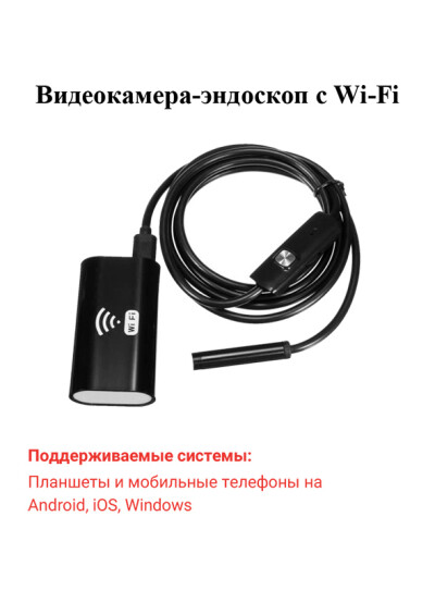
Данная видеокамера-эндоскоп предназначена для рассмотрения, видеофиксации и фотографирования труднодоступных мест. Она представляет собой высококачественную видеокамеру, способную работать в высоком разрешении и закрепленной на гибком основании, Wi-Fi передатчика, посредством которого осуществляется подключение и питание видеокамеры-эндоскопа, и всевозможных аксессуаров: подсветки, микрофона и так далее. Характерной особенностью данного устройства является возможность подключаться к мобильному телефону на базе Android при помощи Wi-Fi. При этом способе подключения в приложение передается живой видеосигнал и звук. Пользователь может произвести запись видео со звуком, а также имеет возможность делать фотографии с камеры.
В представленной инструкции по эксплуатации подробно описан внешний вид изделия и приведены технические характеристики видеокамеры-эндоскопа. Также рассказано о том, как скачать и установить приложение для работы с устройством. Изложены краткие принципы работы с приложением.
Содержание:
- Введение
- Характерные особенности
- Комплект поставки
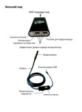
- Внешний вид
- Скачивание приложения
- Использование приложения для смартфона
- Использование приложения для персонального компьютера с Windows
- Использование приложения для персонального компьютера с MacBook OS
- Технические характеристики
Загрузка…
Pipe Inspection Camera System
Operation Manual
【INTRODUCTION】
The pipe inspection camera system is a powerful set of tools that helps you locate and diagnose problems in a pipeline system.
The system is widely used in inspections of Sewer, central air conditioning, chimney, plumbing, building, cable pipe and pipes ventilation systems and other places.
【GENERAL SAFETY RULES】
PRECAUTIONS
Read all safety warnings and instructions. Failure to follow warnings and instructions may result in electric shock, fire and/or serious injury.
Save this operation manual for future reference.
1. Do not operate this device in explosive atmospheres, such as in the presence of flammable liquids, gases, hazardous chemicals, superheated liquid or heavy dust. It may create sparks which may ignite the dust or fumes.
2. The camera head and the push cable are waterproof, however, the DVR and connecter cable are not. Do not expose them to water or rain. This increases the risk of electrical shock.
3. Avoid using the device in environments of extreme cold, heat or humidity as it may damage the device.
4. Do not drop or press hard on the device.
5. Always backup your data before connecting your SD memory card to this system. The manufacturer is not responsible for any data of damage on your SD memory card for any reason.
6. Do not disconnect the unit while recording or playing back. It may damage the unit and/or the SD memory card.
7. Only qualified person are allowed to repair this device. Service or maintenance performed by unqualified person could result in injury.
8. Do not use this device in places where there is high voltage equipment. The device doesn’t contain high voltage protection and isolation.
9. Check or maintain this device regularly, repair it or replace new parts if there is any damage.
【APPLICATION AND KNOW YOUR TOOL】
APPLICATION
Suitable for pipes at diameter of 100mm-400mm.
KNOW YOUR TOOL
The pipe inspection camera system includes the following four main parts: camera head, push cable, meter counter device and LCD monitor.
The camera includes 512Hz transmitter (optional), self-leveling device, adjustable brightness LEDs, high quality anti-scratch sapphire glass lens cover; stainless steel housing; The sapphire glass cover and stainless steel housing can protect the camera from scratching, knocking, etc.
The flexible stainless steel spring and other related components provide a flexible transition; which makes the push cable be easier to pass through bended pipes.
Battery is built into LCD to provide power for camera and DVR monitor.
1
Camera
1. Stainless steel shell
2. Leds
3. Isolation ring
4. Sapphire lens cover
2
1
3
Figure 1.Camera
4
Remote control
1. Menu: Select Menu
2. Playback: Playback
Mode
3 . P t / W t : R e s e r v e
Function
4. Exit: Exit Menu
5 . U p : S e l e c t U p /
Previous Item
57
9
Figure 2. Remote control
6 . O K & H o m e :
Confirm/Select Menu
7. Left: Select Left Item
8. Right: Select Right Item
9. Down: Select Down/Next Item
10. Mirror: Mirror And Flip Image
11. LED: Adjust The Led Brightness
12. REC: Start/Stop Recording
13. Photo: Take Photo
2
64
8
DVR and Bracket
1. Playback: Playback mode
2. Left: Select left item
3. Menu: Select menu
4. Power Indicator LED
5. Exit: Exit menu
6. OK & home: Confirm/Select menu
7. Down: select Down/Next item
8. LED: Change the LED brightness
9. IR for remote control
10. REC: Start/Stop recording
11. Power switch
12. Right: Select right item
13. Photo: Take photo
2
20
19
18
17
16
2
1
3
5
4
PT/WT
OK
HOME
MENU EXIT
6
7
8
9
LED REC
10
11
14
12 13
15
Figure 3.DVR
21
14.USB 2.0 To PC
15. SD card slot
16. Mirror: mirror and flip image
17. UP: select up/previous item
18. PT/WT: reserve function
19. Color TFT LCD
20. Sun visor
21. Aviation cable video head
22.Wheel clip
23.Wing nuts
24.Heavy hex bolts
270°
360°
24
23
22
ITEM
Operating Temperature
Operating Humidity
Storage Temperature
Power adapter
MEAS.
Weight
Sensor
TV-Line
View Angle transmitter
Self leveling
Focus Distance
Depth of field
Camera Size
Camera Length
Front Lens
Shell Material
Lighting
Water-Proof
Power Supply
Current Consume
Screen
Resolution
Mirror and Flip
Video Resolution
Video Encoding
Photograph
Audio Recording
Out Put
External Memory
Data Output
LED Driver
Play Back
Language
Power Supply
Current Consume
Battery Capacity
Life Time
Charge Time
Cable Diameter
Cable Length
Meter Counter
【DESCRIPTION SPECIFICATIONS AND STANDARD EQUIPMENT】
SPECIFICATIONS
General
Camera
DVR
Cable Wheel
PARAMETER
-10°~50°/+14°~+122°
30%RH~90%RH
-20°~60°/+4°~+140°
Input:110VAC~240V AC, Output:12V DC 1500mA
78.5×34.0×89.5cm (LxWxH)
27Kg(Approx)
1/3” Sony CCD
480 TV-Line
120°
512Hz Built-in (Selectable)
Built-in
20cm (approx)
100cm(approx)
¢ 38mm×81mm(Main body)
318mm
Sapphire
304#Stainless Steel
Built-in 12×LED (White)
20m water (Camera fix on Cable)
DC12V
60mA (LED OFF) ; 140mA (LED ON)
7-inch 16:9 super bright high-definition color LCD screen
800×480 RGB
Support image mirror, Flip, Mirror & Flip
PAL 720×576 25FPS Max , NTSC 720×488 30FPS Max
H.264
720×480/720×576
Local Sound
TV and Audio output
Support SD Memory Card up to 32GB
USB2.0 To PC
Built-in Dimmer
Video, Photo and Audio
English, German, French, Spanish, Italian, Chinese, Japanese, Russian,
Portuguese
DC 12V input
700mA Max
7.4V 4400mAh Li-ion Battery
6 Hour
8 Hour
¢ 9mm
60/80/100/120meter (Selectable)
Built-in
3
Standard configuration
Tools kit
P1. Screwdriver
P2. Operation manual
P3. Bolts and nuts (4x)
P4. Inner hexagon spanner
P5. 72 Roller Skid (for pipe diameter 4″-5″)
P6. Car charger
P7. Text writer
P8. Power adapter
P9. 120 universal Skid (for pipe diameter 5 «- 12»)
P10. Hexagon spanner
P11. Remote control
Machine
M1. Wheel
M2. Frame
M3. Coil and push rod
M4. DVR and bracket
M5. Meter counter device
M6. Guide spring
M7. Camera
M8. Handle
P1
M7
M8
P2
P3
M6
M5
M3
M4
4
P11
P10
P9
P4
P5
P6
P7
P8
Figure 4. Standard configuration
M2
M1
【INSTALLATION】
To reduce the risk of serious injury during use, follow these procedures for proper assembly.
1. Install Camera Head (See Figure 5)
Sealing ring
Camera
Glassfiber cable
Guide spring
Take out camera, grip the guide spring and screw the camera head tightly clockwise. Ensure the seal ring and the gold pins are in good status before installing camera head.
Figure 5. INSTALL CAMERA HEAD
2. Meter Counter Device (See Figure 6)
Unlock the adjustable screw.
Tu r n t he g u id e bu sh i ng clockwise rotation until the gap alignment of the open slot in guide shaft. Put the fiberglass cable in the guide shaft along the open slot.
Then turn the guide bushing
Adjustable screw
(2X) negat ive rot at ion t o t he
Max position, locking the adjustable screw.
Figure 6. Meter counter device
Pull and push the fiberglass cable to confirm knurled wheel will not slip.
Press the reset button to reset meter counter, in order to recount.
Fiberglass cable
Reset botton
3. Install Skid
Roller skids are used to keep the camera head in the center of different sized pipes and also to keep camera head away from mud at the bottom of pipes, in order to keep camera head clean and also view best quality images.
There are two kinds of roller skids:
Lockring
Screws
Skid
Camera
Dia. at 120mm — 250mm, adaptive for 5 «-12» pipes
Figure 8. 120 universal Skid
Screws
Lockring
Camera
Skid
Dia. at 72mm, suitable for 3 «-4» pipes
Figure 7. 72 Roller Skid
1 ) 72 Roller Skid (dia. at 72mm, suitable for
4″-5″pipes) .(See Figure 7)
2) 120 universal Skid (dia. at 120mm — 250mm, adaptive for 5 «-12» pipes) . (See Figure 
Please choose an appropriate skid according to the size of the pipe. Put the camera into the skid, press and lock the lockring properly.
4. Install Handle (See Figure 9)
This product includes an extension handle for people with different height to operate it.
Take out the handle and bolt pack from tool bag, align the four holes in the handle frame, fit with bolts, washers, and finally tighten the whole hexagon lock-nuts.
5
Handle
Frame
Washers
Hexagon Lock-Nut
Bolts
Figure 9. Install handle
5. Install The Wheel Assembly (See Figure 10)
Take out the wheel assembly from the package, unscrew the nuts and washers, fit the bolt into wheel hole and finally tighten the Hexagon Lock-Nuts.
Hexagon Lock-Nut
Washers
Holes
Wheel Assembly
Figure 10.Install the wheel assembly
6
【FUNCTION GUIDE AND OPERATING INSTRUCTIONS】
DVR ICON
1. SD Card
2. Battery Level
3. Image Reverse
4. Image Reverse & Mirror
5. Image Mirror
6. Timestamp
7. LED Brightness
8. Record
9. Meter Counter (optional function)
1.83m 6.0ft
9
SD
1
8 7 6
12:34:56
Figure 11. Screen icon Definition
5
2
3
4
[FUNCTION GUIDE]
1. Live video
Press to turn on/off DVR to enter the live video mode, then press to enter playback mode.
Press to start/stop recording.
Press to mirror or/and reverse the image.
Press adjust the brightness of camera LEDs.
Press to take a picture.
2. Video Option
Press to enter the video option menu. Press and to select items that you need, press to confirm the selection. Press or to change the value. Press to save the setting. Press to exit video option and save.
• Size D1 (720*576) / VGA (640*480) / QVGA (320*240)
• Video Seg: 10min/20min/30min/40min/OFF. Set 10-40min to restrict files length and open cycle-cover. Elder files will be covered by new files when SD card is full. Set OFF to close this function.
• Meter Counter: Reserve function.
• Sound: Turn on/off the local sound in Video Recording.
• Timestamp: Enable/Disable time stamp on screen.
3. Playback
Press the button to enter the playback, the user can browse, preview and playback media files.
Press and to browse and select media files.
Press to confirm the selection and preview media file. Press to preview the previous file. Press to preview the next file. Press to playback video. Press to enter the play setting.
• Delete: Delete media files.
• Slide Show: 3sec/5sec/10sec. To set interval time of the slide shows.
• Protection: To protect important media files.
• Thumbnail: Browse 9 media files per page.
• File List: Browse 3 media files per page.
• LCD: LCD brightness.
4. Playing Movie
Pause/Play movie, Stop play movie, Rewind, Forward, you can press to set speed rate of rewind/forward.
5. SETUP
Press to enter the preferences of Record/Playback. Press enters Setup menu.
The following items are in the setup menu.
• Format: format SD card.
• LCD: LCD brightness.
• Language: English, German, French, Spanish, Italian, Chinese, Japanese, Russian, Portuguese.
• Sys. Reset: Reset all setting.
• Light frequency, 50Hz/60Hz, specifying your ambient light frequency.
• TV output: PAL/NTSC.
• Date input: To set date and time.
7
8
【USER MANUAL】
At the Job Site
1. Always wear rubber gloves to operate the camera for health and safety reasons. Properly positioning the cable reel will save time and strength to push out and in the cable, and minimize the rate of equipment damage.
• When pushing, the end of your stroke should be as close to the entry as possible. Standing too far back with an excess of cable between your hands and the entry may cause the cable to fold on itself outside the entry and damage the cable.
• Try to keep the push cable away from sharp edge of a pipe entry because this may cause damage. If the camera does not seem to go any farther, DO NOT FORCE TO PUSH THE CAMERA! Try another entry if possible.
□ □ □ □ □ □ □ □ □ □ □ □ □□□ □ □ □□□ □ □ □□ □□ □ □□□ □ □ □ □ □□□ □ □ □ □ □ □ □ □□□ □ □□ □ □ □ □□□ □ □ □□ □ □ □ □ □
□□ □ □ □ □□□□ □ □ □ □ □ □□□□ □ □ □□ □ □ □ □
2. Always try to run water down the pipe under going inspection. This will keep the system much cleaner, and allow you to push noticeably farther with less friction. If the water is preventing you from seeing an area of importance, temporarily turn it off.
3. When push the push cable through the pipeline by steady and slowly, a short distance entry per time, keeps the hands at the entrance, so that can control the push cable and prevent it stuck, bent or scratch.
4. When inspecting a pipe, most of the time a slow steady push through the system works the best. At changes in direction such as P-traps, Tee’s, Y’s, Elbows, etc. It is usually necessary to give a little extra push in the bends. Back the camera head approximately 8″ (20cm) from the bend, if necessary, and give it a quick push, “popping” the camera through a turn, using the least amount of force required. Try to be as gentle as possible, and do not hammer or snap the camera head through corners. After some practice, you may learn that the best way to inspect a section of pipe is to push the camera through quickly. Then draw the camera back home slowly and evenly.
5. Make sure the sapphire window is clean prior to entry. Some users claim that a slight film of detergent on the lens minimizes the possibility of grease sticking to the port. If necessary, take advantage of any standing water in the pipe to wash the front of the camera by jiggling it in the water.
6. When you place the camera head into the pipe remember, as the materials of pipe vary, it will be necessary to adjust the lighting settings to maximize picture quality.
7. The system can travel through multiple 45 and 90 degree bends and wyes. Do not, however, try to force it through a P-trap or tee if there is a large amount of resistance.
□ □ □ □ □ □ □ □□ □□□ □□ □ □ □ □□ □ □ □ □ □□□ □ □ □ □ □□ □□□ □□
□ □ □□□□ □□□□ □ □ □ □□□ □ □ □□□ □ □□ □ □□□ □ □ □ □□□□ □□ □□ □ □□
□ □□ □□□ □□□ □ □ □□ □ □□□ □ □□ □ □ □ □ □□ □ □ □ □ □ □□ □□□ □□
□ □ □□□ □ □□□□ □ □ □ □ □□□ □ □ □ □ □ □ □□ □ □ □ □ □ □ □ □ □ □ □ □ □
□ □ □ □ □ □□ □□ □ □ □ □ □ □ □□ □□ □□ □ □ □ □□□□ □□□□ □
8. Do not attempt to remove or stores push cable on the reel
Figure 12. Improper operation solely by turning the reel itse if. You can manually push or pull cable from the reel and wind or unwind it.
9. If the camera sits in a pipe, or an enclosed environment, heat will build-up. This may lead to the camera head overheating which will cause fuzzy lines to appear on the monitor. In the event, this happens, turn off the system, remove the camera from the pipe (or enclosed environment) and let the camera head cool for 10 to 15 minutes. Running water into the line will also help cool the camera head. Always use the minimum illumination required to maximize picture quality and to avoid excessive heat build-up.
□ □ □ □ □ □ □ □ □ □ □□ □ □ □ □ □ □ □ □ □ □□ □ □ □ □ □ □ □ □□□□□ □ □ □ □ □□□ □ □ □□ □□ □ □ □ □□□□ □ □□ □□
□□ □□□ □ □ □□□□□ □ □ □ □ □□□ □ □ □□ □□ □ □ □□ □□□ □□ □□ □ □□ □ □ □ □□□□ □ □□□□ □□□ □□ □ □ □ □□□ □
Retrieving the push cable
1. Once the inspection has been completed, pull the push cable back with slow, steady force. Do not force the push cable or exert excessive force. This could damage the camera or push cable. The push cable may get hung up while being retrieved, and may need to be manipulated as did during insertion.
2. Once the inspection has been completed, pull the push cable back with slow, steady force. Do not force the push cable or exert excessive force. This could damage the camera or push cable. The push cable may get hung up while being retrieved, and may need to be manipulated as did during insertion.
□ □□□ □ □ □ □ □ □ □ □ □ □ □ □ □ □ □ □ □□ □□□ □ □ □ □ □ □ □ □□ □□ □□ □ □ □ □□□ □ □ □ □ □□□ □ □ □ □ □□□ □
□ □ □□□ □ □ □ □ □ □□□ □□ □ □□□ □ □ □ □ □ □□ □□□ □ □ □ □ □ □ □ □ □□ □ □ □□□ □ □□ □□ □ □ □ □ □□ □ □□□ □
□ □ □□□ □□□□ □□ □ □□□ □ □ □ □ □ □ □ □
□ □□□ □
3. Storing the push cable into the cable reel. One hand holds the push cable, the other hand close to the cable wheel. Slowly and gently push the push cable slide via the hook of the handle, cable reel will rotate and store the push cable inside.
□ □□□ □ □ □ □ □ □ □ □ □ □ □ □□□ □ □ □□□ □ □ □□ □□ □ □ □ □□□ □ □ □ □□ □ □ □ □ □□□□□□ □ □□ □ □ □ □ □ □ □ □□□
□ □ □ □ □□ □ □ □ □ □ □ □ □□□ □ □ □ □□□ □□□ □ □ □ □ □□□ □□□ □ □ □ □ □ □□ □ □ □□□□□ □ □ □ □ □ □ □ □ □ □ □ □□ □ □ □ □ □
□ □ □□□ □ □ □ □ □□ □□□ □ □ □
[BATTERY SAFETY AND USING GUIDE]
Using safety
Read the following battery precautions before using the battery and charger, to reduce the risk of electrical shock.
1. Recharge batteries with accessory charging units.
2. Check the power units and battery every time before using the equipment, be sure no problem, use of unauthorized parts may result in electrical shock, fire and/or serious personal injury or damage other instruments and system.
3. Never connects the car charger to any 24 volt cigarette lighter slot. It will harm the battery and DVR.
4. Do not short circuit, it may cause fire, electrical shock.
5. Do not charge the battery under rain or wet conditions. Water entering the charger will increase the risk of electrical shock.
6. If the charger and battery are damaged, do not use or stop to charge. It may cause electrical shock.
7. Don’t disassemble the case, only qualified repair person can repair and maintenance.
8. Properly dispose of the battery. Exposure to high temperatures can cause the battery to explode. So do not dispose of in a fire. Some countries have regulations concerning battery disposal. Please follow all applicable regulations.
9. Do not touch anything which out from battery, which would burn or damage the skin, once touches please flush with water. If in eyes, immediately get medical help fast.
Using Guide
Follow the steps as below to reduce the injury of the electric shock.
1. Power indicator LED will be red during charging, will be turned to green when charged fully. If battery empty for a long term, it will pre-charge the battery automatically in 10 minutes, and LED will be blinking in red.
2. It needs about 8 hours to charge the battery fully. The battery can charge online, charging and supplying of work will not increase charging times.
3. User can use a power adaptor or car charger to charge the battery. If no use in a long term, take a recharge per 6 month, to ensure the battery in normal working status.
Tips
User can use a power adaptor or car charger to charge the battery. Also can directly supply the system without battery.
The power indicator LED will be red during charging, will be turned to green when charged fully.
If no use in a long term, take a recharge per 6 month, to ensure the battery in normal working status.
9
10
[OTHERS]
Troubleshooting
Problem
Meter is not accurate
No image
DVR Can not boot
Probable fault location
Knurled wheel slip not set to zero
Cable connection faulty or loosely
Camera connector soiled
Wrong SD memory card
Wrong setting
No power
Transient short circuit in the cable cause the battery short circuit protection.
Solution
Fit glassfiber cable into the guide solt and hook.
Press reset button to set zero.
Check cable connection, clean and reconnect if necessary
Clean the camera connector
Turu off power and replace SD card
Enter the setup menu and select reset
Recharge
Recharge the DVR more than 2 seconds with adaptor or car-charger to activate the battery.
FCC Statement
This device complies with part 15 of the FCC Rules. Operation is subject to the following two conditions:
1. This device may not cause harmful interference.
2. This device must accept any interference received, including interference that may cause undesired operation. Any changes or modification not expressly approved by the party responsible for compliance could void the user’s authority to operate the device.
CE
This product complies with standards including Low Voltage Device Directive 73/23/EEC;
EMC
Directive 89/336/EEC. It passed the subject tests by the authority concerned and is authorized to bear CE mark.
KEY FEATURE
1. Character key
• 26 English letters.
• 10 Arabic numerals.
• 13 symbols.
2. Function key
Enter key, confirm typing.
Del key, delete character.
Key, move the cursor to left.
Key, move the cursor to right.
Shift key, switch English letters and Arabic numerals.
Caps Lock key, switch capital letters and small letters.
Figure 17. Text Writer
TYPE OPERATION
1. Turn on the screen.
2. Make the Text Writer point to screen then press character keys.
3. Press the same key again to select letters circularly. No operation or press other keys in 2 Seconds to confirm current characters.
4. Press REC key on DVR to record the Video with characters.
5. You can type and edit characters while recording, the typing and editing will be recorded in the video also.
Notes:
Reboot the DVR will lose all characters on screen. The characters on screen cannot be recorded on photos.
11
12
3
4
5
No. Part Number
1 8-956
Part Name
Castor Skid
2 8-967 POM Skid
Optional Part List
Specifications
POM
¢
134×83.9
30mm Wheel (Optional)
POM
¢
78×83.9 (Optional)
6
7
8-978
8-989
9-012
4-602
1-323
Ball Support POM S
¢
60×53.5 (Optional)
Lock Sleeve POM
¢
54.6×38(Optional)
Maintenance
Cable
Camera Head
The parts for fiberglass
Connector (15pcs)
Cable with 6Pin aviation plug and 4Pin aviation plug. 2.1 meter long. Use to connect panel(7-823) and Simple version
Equipment(6-801).
Sony CCD 480TVL Φ38×81mm,
120° View Angle
Self-Leveling
With 512Hz Transmitter
Picture
2
3
4
5
No. Part Number
1 1-312
Part Name
Camera Head
2-312
2-323
3-412
3-423
Adaptor
Car Charger
Remote Control
Text Writer
Part Number List
Specifications
Sony CCD 480TVL, Φ38×81mm,
120° View Angle
Self-Leveling
DC 12V 1. 5A Adaptor
DC 12V 2A Car Charger
13 Key Remote Control
20Key Text Writer
6 5-623 DVR
7-Inch Video Recorder, 14Key
Built-In Battery With Aviation Socket
7
8-934 72 Roller Skid Suitable For 4″-5″ pipes
8
8-945
120 Universal
Skid
Suitable For 5″-12″Pipes
9
10
11
12
9-412
6-801
4-601
9-423
Handle
¢
22×281×242
Simple version
Equipment
A complete set of Equipment without
DVR(5-623) and Bracket(9-423). Provide one Cable(4-602) to connect other panel.
Cable
Spiral cable with 6Pin aviation plug. 71cm long. Use to connect DVR(5-623) and wheel.
Bracket Standard
Picture
13
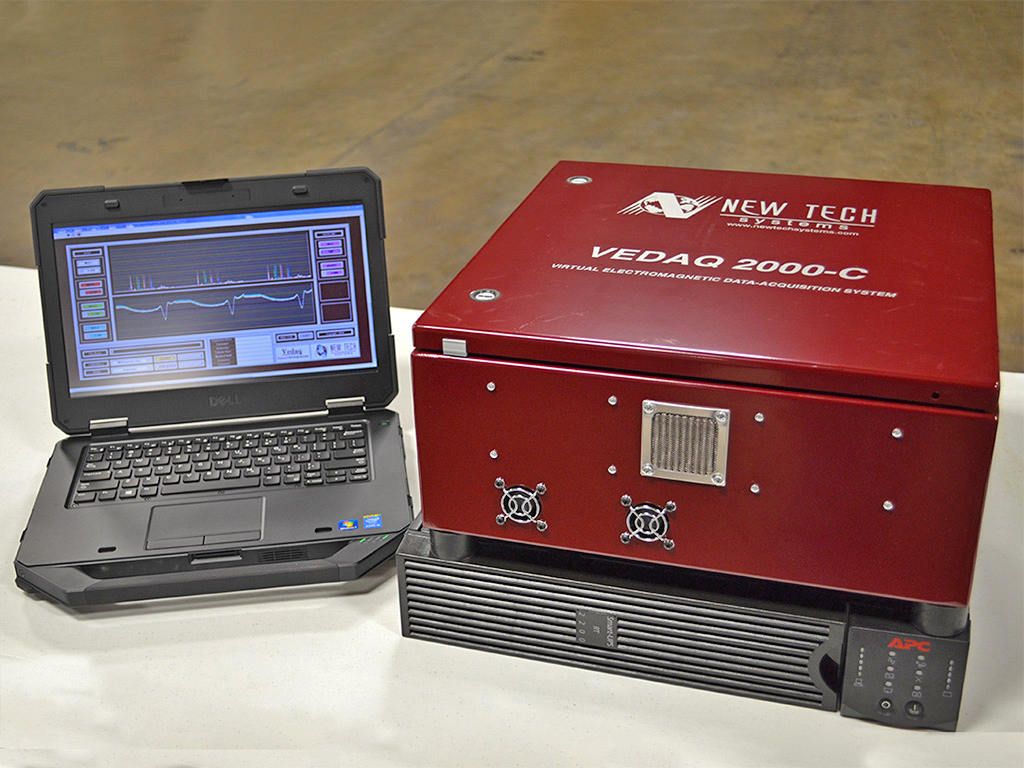
VEDAQ 2000-C
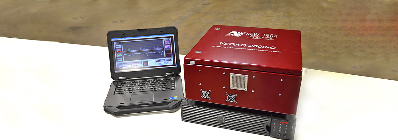
The VEDAQ 2000-C™ Portable Multi-Function EMI Drill Pipe Inspection System for drill pipe up to 6-5/8″ O.D.
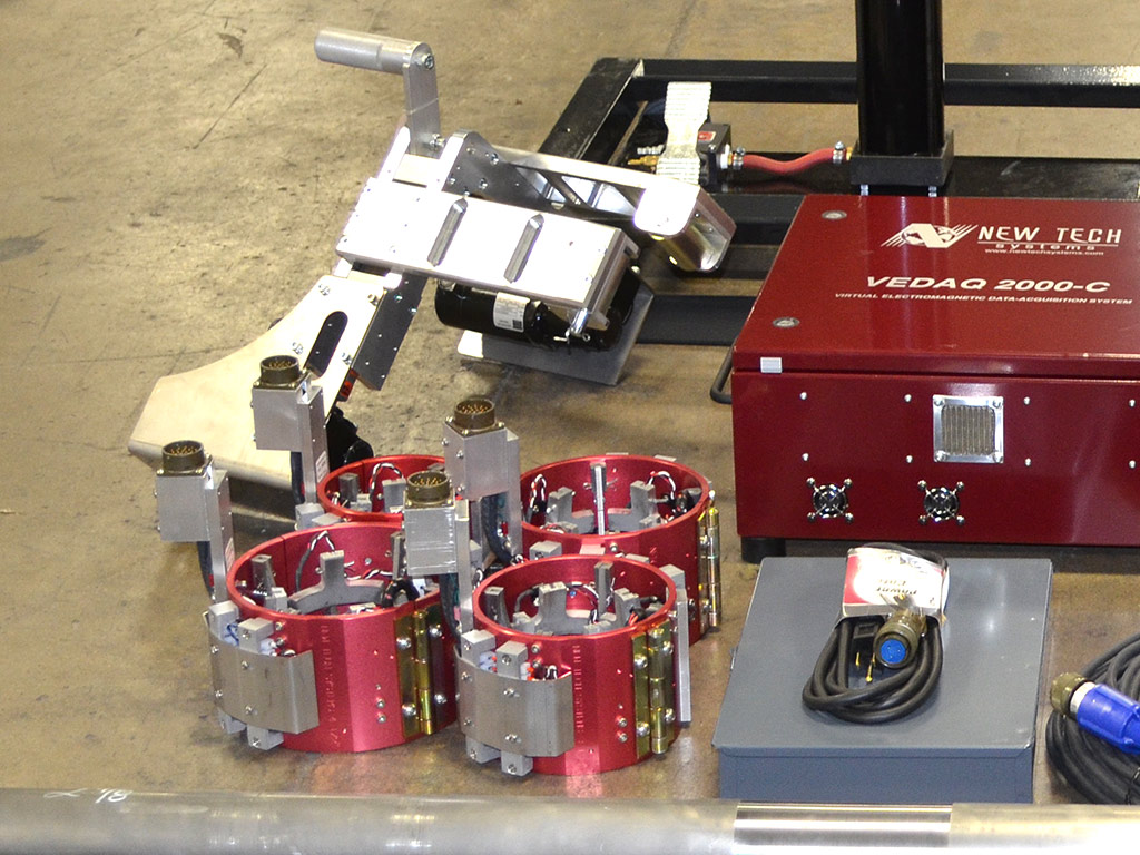
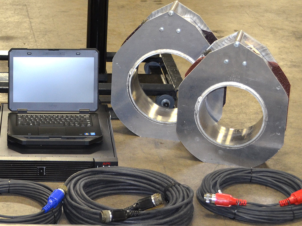
The VEDAQ 2000-C™ is a portable, computerized, multi-function EMI system for inspecting drill pipe and tubing. Transverse flaw detection and TRUEWALL™ solid state (Hall effect) wall monitoring functions are standard on the VEDAQ 2000-C™. It’s lightweight, compact and extremely portable design allows the VEDAQ 2000-C™ to be operated at the rig site or in a pipe yard. Commands (i.e. gain, coil, buggy adjustments) are controlled on the computer. The inspection results are displayed digitally in the software with individual channel colors for easy interpretation. The VEDAQ 2000-C™ is designed to meet most industry requirements set forth by API, DS-1, etc.
Product Specifications
| Technical and Performance Data | |
| Capacity: | 2 3/8″ to 6 5/8″ O.D. drill pipe and tubing |
| Functions: | Transverse flaw detection (MFL) TRUEWALL™ magnetic wall thickness monitoring (MFD) |
| Data Acquisition: | Data acquisition system with Dell laptop computer (all functions performed on computer with multi-color data display) |
| Production Rate: | Up to 150 ft /minute |
| Inspection Criteria: | The VEDAQ 2000-C™ is designed to meet most industry specifications (i.e. API, DS-1, etc.) |
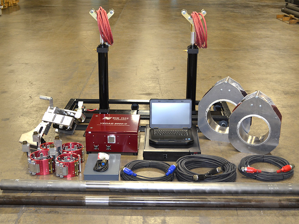
| Major Components: | Electronics console Dell laptop computer with VEDAQ software Power, signal, and buggy drive cables High speed buggy drive with variable speed DC motors Powerful DC magnetizing coils Air jack set (standard or Hi-Low models available) Buggy heads (sizes optional) Calibration standards (sizes optional) |
Product Images
Mode of Operation
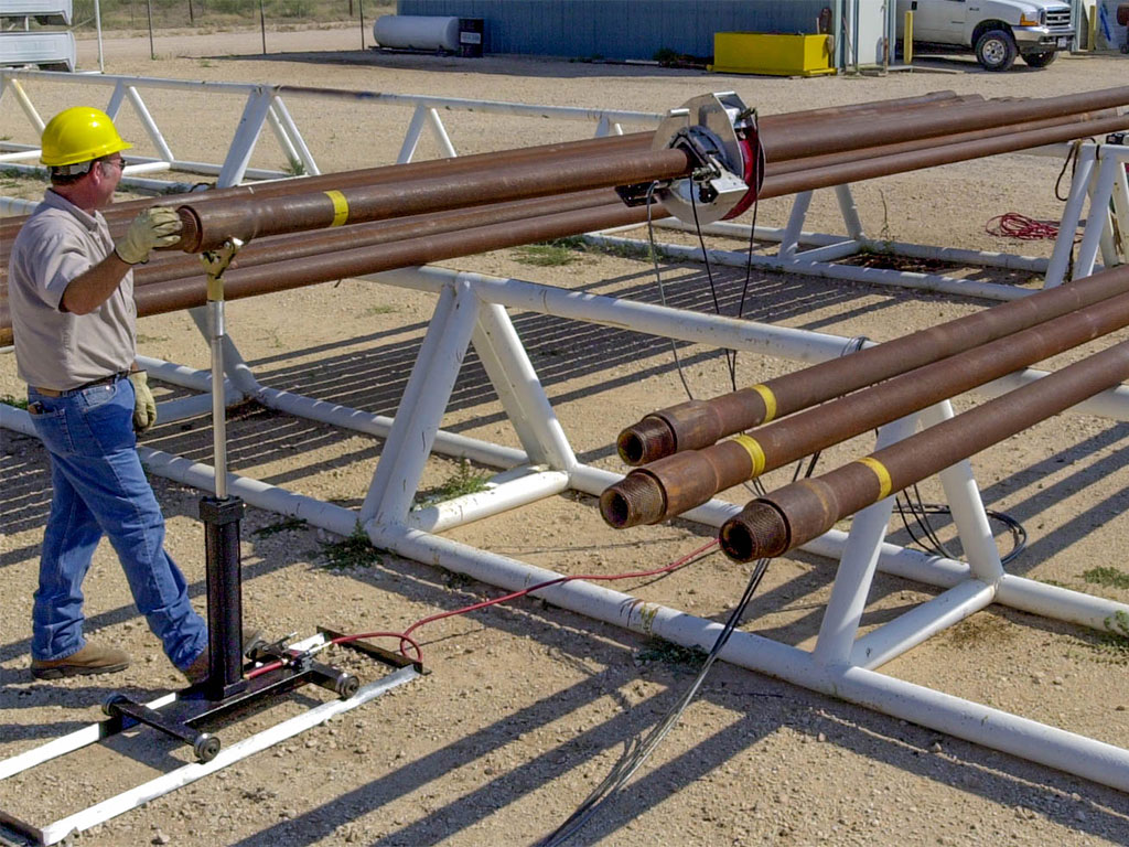
The system is calibrated on a standard at the beginning of the job. The magnetizing coil is placed over the end of the pipe. The buggy drive and head are placed on top of the pipe and the mag coil is placed on the buggy drive. The air jacks lift the pipe so the coil & buggy will clear the pipe racks.The electronics operator then powers the buggy down the pipe and starts the computer while observing the data on the software. When the buggy reaches the other end of the pipe, the jacks lower the pipe to the racks, the buggy and coil are removed and placed on the next pipe. The process is then repeated in the opposite direction.
Product Info Download
PDF Specification


