- Manuals
- Brands
- Planmeca Manuals
- Medical Equipment
- Planmeca ProMax 3D Classic
Manuals and User Guides for Planmeca Planmeca ProMax 3D Classic. We have 8 Planmeca Planmeca ProMax 3D Classic manuals available for free PDF download: Technical Manual, User Manual
Planmeca ProMax
®
3D s & 3D Classic with ProTouch user’s manual
3D imaging
TABLE OF CONTENTS
1 INTRODUCTION ………………………………………………………………………………….1
2 ASSOCIATED DOCUMENTATION ………………………………………………………..2
3 SYMBOLS ON PRODUCT LABELS ……………………………………………………….3
4 SAFETY PRECAUTIONS ……………………………………………………………………..4
5 SWITCHING X-RAY UNIT ON ……………………………………………………………….6
6 MAIN PARTS ………………………………………………………………………………………7
6.1
General view of X-ray system ……………………………………………………………………………. 7
6.2
General view of X-ray unit …………………………………………………………………………………. 8
6.3
Sensors ………………………………………………………………………………………………………….. 9
6.4
Patient supports …………………………………………………………………………………………….. 10
6.5
Exposure switch …………………………………………………………………………………………….. 11
6.6
Emergency stop button …………………………………………………………………………………… 12
6.7
Touch screen ………………………………………………………………………………………………… 13
6.8
Patient positioning controls ……………………………………………………………………………… 15
7 PLANMECA PROMAX 3D S PROGRAMS …………………………………………….16
7.1
3D Dental ……………………………………………………………………………………………………… 16
8 PLANMECA PROMAX 3D CLASSIC PROGRAMS ………………………………..17
8.1
3D Dental ……………………………………………………………………………………………………… 17
8.2
3D Models …………………………………………………………………………………………………….. 17
9 3D PATIENT EXPOSURE ……………………………………………………………………18
9.1
Preparing X-ray system ………………………………………………………………………………….. 18
9.2
Selecting exposure settings …………………………………………………………………………….. 25
9.3
Preparing patient ……………………………………………………………………………………………. 31
9.4
Patient positioning ………………………………………………………………………………………….. 31
9.5
Adjusting volume position ……………………………………………………………………………….. 33
9.6
Taking a scout image or 2D views (LAT, PA or LAT-PA) …………………………………….. 37
9.7
Taking a 3D exposure …………………………………………………………………………………….. 39
10 3D FACE PHOTO ……………………………………………………………………………….40
10.1 Before exposure …………………………………………………………………………………………….. 40
10.2 Selecting exposure settings …………………………………………………………………………….. 40
10.3 Patient positioning ………………………………………………………………………………………….. 40
10.4 Taking a 3D face photo …………………………………………………………………………………… 42
11 3D MODEL EXPOSURE ……………………………………………………………………..43
11.1 Calibrating X-ray unit for impression or plaster material ………………………………………. 43
11.2 Taking an exposure of an impression or plaster cast ………………………………………….. 47
12 SETTINGS …………………………………………………………………………………………50
12.1 User settings …………………………………………………………………………………………………. 50
13 CLEANING ………………………………………………………………………………………..53
14 SERVICE …………………………………………………………………………………………..53
15 DISPOSAL ………………………………………………………………………………………..54
16 HELP MESSAGES ……………………………………………………………………………..55
User’s Manual (3D)
Planmeca ProMax 3D s & 3D Classic with ProTouch 1
TABLE OF CONTENTS
17 ERROR MESSAGES ………………………………………………………………………….57
18 TECHNICAL SPECIFICATIONS …………………………………………………………..58
18.1 Technical data for Planmeca ProMax product family …………………………………………… 58
18.2 Original manufacturer …………………………………………………………………………………….. 62
18.3 Dimensions …………………………………………………………………………………………………… 62
18.4 Minimum operational space requirements …………………………………………………………. 63
The manufacturer, assembler, and importer are responsible for the safety, reliability and performance of the X-ray unit only if:
— installation, calibration, modification and repairs are carried out by qualified authorized personnel
— electrical installations are carried out according to the appropriate requirements such as IEC 60364
— equipment is used according to the operating instructions
Planmeca pursues a policy of continual product development. Although every effort is made to produce up-to-date product documentation this publication should not be regarded as an infallible guide to current specifications. We reserve the right to make changes without prior notice.
COPYRIGHT PLANMECA
Released: 17 March 2014
Publication part number: 10033255 revision 6
2 Planmeca ProMax 3D s & 3D Classic with ProTouch
User’s Manual (3D)
INTRODUCTION
1 INTRODUCTION
Settings
(Top left corner of main view)
This manual describes how to take 3D exposures. The manual applies to:
• Planmeca ProMax 3D s X-ray unit
• Planmeca ProMax 3D Classic X-ray unit
NOTE This manual is valid for software version 3.3.3.0.r or later. This software version is compatible with
Planmeca Romexis software version 3.5.0.r or later.
To check the software version of your X-ray unit, select
Settings > About > 4100 Component Information >
ProMax SW version.
The X-ray unit uses Cone Beam Computed Tomography
(CBCT) to produce three-dimensional (3D) X-ray images.
Panoramic, cephalometric and projection radiography techniques can be used for two-dimensional (2D) X-rays.
If the X-ray unit has a ProFace sensor, you can take a 3D photo of the patient’s face.
The X-ray images can be used for examination of dentomaxillofacial anatomy. The 3D face photo can be used for patient education or in order to follow the results of medical treatments.
You need a PC with the Planmeca Romexis program in order to save, view and modify the images.
Make sure that you are fully acquainted with the appropriate radiation protection measures and these instructions before you use the X-ray unit.
NOTE The X-ray unit may be used by health care professionals only.
User’s Manual (3D)
Planmeca ProMax 3D s & 3D Classic with ProTouch 1
ASSOCIATED DOCUMENTATION
2 ASSOCIATED DOCUMENTATION
The X-ray unit is supplied with the following manuals:
• User’s Manual(s) for
— 3D Imaging, Original English publication: 10033255
(- 2D Imaging, Original English publication: 10033256, optional)
(- Cephalostat, Original English publication: 10033034 or
10033035, optional)
• Installation Manual,
Original English publication: 00688271
• Technical Manual,
Original English publication: 10033257
These manuals are intended to be used in conjunction with the documentation for the Planmeca Romexis program. The Romexis package contains the following manuals:
• User’s Manual, Original English publication: 10014593
• Installation Manual,
Original English publication: 10014600
2 Planmeca ProMax 3D s & 3D Classic with ProTouch
User’s Manual (3D)
3 SYMBOLS ON PRODUCT LABELS
SYMBOLS ON PRODUCT LABELS
0598
CE marking according to European standard
(Directive 93/42/EEC)
SGS marking according to US and Canadian standards
(ANSI/UL 60601-1 and CAN/CSA C22.2 No. 601.1-M90)
Date of manufacture (Standard ISO 15223-1)
Attention, consult accompanying documents
(Standard IEC 60601-1)
Type B applied part (Standard IEC 60601-1)
Separate collection for electrical and electronic equipment
(Directive 2002/96/EC WEEE)
Alternating current (Standard IEC 60417)
Electrostatic sensitive device (Standard IEC 60417)
User’s Manual (3D)
Planmeca ProMax 3D s & 3D Classic with ProTouch 3
SAFETY PRECAUTIONS
4 SAFETY PRECAUTIONS
CAUTION FOR US USERS:
Federal law restricts this device to sale by or on the order of a health care professional.
CAUTION This X-ray unit may be dangerous to both patient and operator unless safe exposure values are used and correct operating procedures are observed.
CAUTION The patient positioning lights are laser lights. Do not stare into the laser beam.
CAUTION Do not drop the sensor. Planmeca limited warranty does not cover damage which is due to misuse, e.g. dropping the sensor, neglect, or any cause other than ordinary use.
If you have any reason to believe that the sensor might be faulty, take a test exposure before taking a patient exposure.
CAUTION If an exposure is interrupted (e.g. exposure button is released or emergency stop button activated), the patient must be guided away from the X-ray unit before the C-arm is moved.
CAUTION Do not connect items which are not specified as part of the system.
CAUTION Do not connect a multiple portable socket outlet (MPSO) or extension cord to the system.
CAUTION Do not touch an electrical connector and the patient at the same time.
CAUTION If the X-ray unit shows any signs of oil leakage, disconnect the unit from mains and contact your service technician for help.
CAUTION Do not use the X-ray unit in an oxygen rich environment or in the presence of flammable anesthetics.
CAUTION Never use a defective or damaged X-ray system. Contact your service technician for help.
NOTE It is very important that the place where the unit is to be used and the position from which the user is to operate the unit are correctly shielded. Since radiation safety requirements vary from country to country and state to state it is the responsibility of the user to ensure that all local safety requirements are met.
NOTE Cone beam imaging should not be used for routine (or screening) examinations. The imaging examinations must be justified for each patient to demonstrate that the benefits outweigh the risks.
NOTE When it is likely that evaluation of soft tissues will be required as part of the patient’s radiological assessment, conventional CT or MR medical imaging should be used rather than CBCT.
4 Planmeca ProMax 3D s & 3D Classic with ProTouch
User’s Manual (3D)
CAUTION
LASER RADIATION —
DO NOT STARE
INTO BEAM
1mW
635nm
CLASS II
LASER
PRODUCT
CLASS 1 LASER PRODUCT
APPAREIL À LASER DE CLASSE 1
IEC 60825-1:2007
User’s Manual (3D)
SAFETY PRECAUTIONS
NOTE Before taking an exposure, ask any female patient of childbearing age whether she might be pregnant. The
X-ray unit is not intended for use on pregnant women.
NOTE FOR CANADIAN USERS:
All patients must be provided with a shielded apron for gonad protection and a thyroid shield. The use of a thyroid shield is especially important in children. The shielded apron and thyroid shield should have a lead equivalence of at least 0.25 mm on both sides (front and back of the patient).
NOTE If the X-ray unit has been stored at temperatures under
+10°C for more than a few hours, time must be allowed for the unit to reach room temperature before turning it on.
NOTE Ensure efficient air conditioning in the X-ray room. It is recommended to keep the room temperature between
+20°C and +25°C at all times.
NOTE If exposures are taken in rapid succession the X-ray tube may overheat and a cooling time will flash on the touch screen. The cooling time indicates the delay before the next exposure can be taken.
NOTE If the X-ray system is not connected to an
Uninterruptible Power Supply (UPS), disconnect the system from mains during lightning storms.
NOTE FOR US & CANADIAN USERS:
The patient positioning lights are class II laser products (21 CFR § 1040.10).
NOTE FOR EUROPEAN USERS:
The patient positioning lights are class 1 laser products (Standard IEC / EN 60825-1: 2007).
NOTE EMC requirements have to be considered, and the equipment must be installed and put into service according to the specific EMC information provided in the accompanying documents.
NOTE Portable and mobile RF communications equipment can affect the X-ray unit.
NOTE External equipment intended for connection to signal input, signal output or other connectors, shall comply with relevant IEC standard (e.g. IEC 60950 for IT equipment and the IEC 60601 series for medical electrical equipment). In addition, all such combinations — systems — shall comply with the standard IEC 60601-1-1, Safety requirements for medical electrical systems. Equipment not complying to IEC 60601 shall be kept outside the patient area
(more than 2m (79 in.) from the X-ray unit).
Any person who connects external equipment to signal input, signal output or other connectors has formed a system and is therefore responsible for the system to comply with the requirements of IEC 60601-
1-1. If in doubt, contact your service technician or local representative for help.
NOTE Contact your service technician if you notice a decrease in image quality.
NOTE Contact your service technician if you have taken an exposure but the image does not appear in the
Planmeca Romexis program. The last ten images can be manually imported into Romexis.
NOTE Never place or hang any objects on any part of the Xray unit.
Planmeca ProMax 3D s & 3D Classic with ProTouch 5
SWITCHING X-RAY UNIT ON
Glass windows
NOTE Make sure that neither you nor your patient can get caught or hooked up on any part of the X-ray unit.
Keep loose items of clothing, hair and jewellery tucked away safely.
NOTE If you have any reason to believe that the C-arm might hit the patient during exposure (e.g. patients with wide shoulders), take a test exposure without radiation first. To switch radiation off, select Settings > User >
1300 Operational settings > 1310 User Mode > 1311 Set
Demo Mode.
NOTE Do not touch the arm structures when the X-ray unit is moving.
NOTE Patients are not allowed to hang on the patient handles.
NOTE FOR PROFACE SENSOR:
Do not touch the glass windows. Fingerprints or other stains on the glass surface destroy image quality.
ProFace sensor
5 SWITCHING X-RAY UNIT ON
Stationary column top
The on / off switch is located on the underside of the stationary column top.
On / off switch
NOTE To prolong the lifetime of the X-ray unit, always switch the X-ray unit off when it is not in active use.
6 Planmeca ProMax 3D s & 3D Classic with ProTouch
User’s Manual (3D)
6 MAIN PARTS
6.1
General view of X-ray system
1
2
3
MAIN PARTS
Ethernet
1. X-ray unit
2. 3D reconstruction PC
3. Planmeca Romexis program
User’s Manual (3D)
Planmeca ProMax 3D s & 3D Classic with ProTouch 7
MAIN PARTS
6.2
General view of X-ray unit
Telescopic column
Stationary column
C-arm
3D sensor
Patient support table
Patient handles
Patient positioning controls
Touch screen
Chair
(included in delivery)
8 Planmeca ProMax 3D s & 3D Classic with ProTouch
User’s Manual (3D)
MAIN PARTS
6.3
Sensors
1
2
3
1. 3D sensor for Planmeca ProMax 3D s
2. 3D sensor for Planmeca ProMax 3D Classic
3. ProFace sensor for Planmeca ProMax 3D s and Planmeca ProMax 3D Classic
User’s Manual (3D)
Planmeca ProMax 3D s & 3D Classic with ProTouch 9
MAIN PARTS
6.4
Patient supports
6.4.1
Head supports (A or B)
A)
2
1
3
2
Head_suppor t_attach_2.eps
4
B)
1
2
1. Adjustable head support
2. Temple pads for children
3. Fastening straps
4. Support bars
1. Head band 25
2. Support bars
10 Planmeca ProMax 3D s & 3D Classic with ProTouch
User’s Manual (3D)
MAIN PARTS
6.4.2
Chin supports
1 2
3
6.5
Exposure switch
Exposure switch
Exposure button
1) Flashing green =
Getting ready
2) Continuous green =
Ready
3) Yellow = Radiation
1. Chin cup
2. Chin support
3. Adjustable adapter
The exposure switch can be mounted on the wall, or it can be hung from the hook provided on the stationary column top if a protected area is within reach.
Green lights flash on the exposure button and on the touch screen when the X-ray system is getting ready for an exposure. The green lights stop flashing and stay on continuously when the X-ray system is ready for an exposure.
During exposure yellow radiation warning lights illuminate on the exposure switch and on the touch screen. They indicate that the X-ray unit is generating radiation.
User’s Manual (3D)
Planmeca ProMax 3D s & 3D Classic with ProTouch 11
MAIN PARTS
6.6
Emergency stop button
The emergency stop button is located on the top of the stationary column. Press the button to stop the X-ray unit operating in an emergency. When the emergency stop button is pressed down, all movements of the X-ray unit are blocked and the unit will not generate radiation. The up / down movement will stop within a distance of 10 mm
(0.4 in.).
A help message will appear on the touch screen. Guide the patient away from the X-ray unit. Then release the emergency stop button. The X-ray unit will automatically restart.
12 Planmeca ProMax 3D s & 3D Classic with ProTouch
User’s Manual (3D)
MAIN PARTS
6.7
Touch screen
NOTE The options shown on the touch screen depend on the unit configuration. The X-ray unit can be upgraded with new programs and features, contact your dealer for further information. The views and values shown in this manual are only examples.
NOTE The illustrations shown on the touch screen are based on approximate patient anatomy. The actual volume position depends on the individual anatomy of the patient.
NOTE Never allow patients to touch the screen when they are positioned in the X-ray unit. Touching the screen during exposure will stop the imaging process.
You can use the buttons at the bottom of the main screen to change the appearance of the main view.
Show ProMax model and up to five most recently used programs
(with most recent first)
Show both program bars
Left button
(default view)
Fast forward
Right button
NOTE If you wish to use fast forward buttons on the default view (left button), select Settings > Program > 2200
Program Features > Fast Forward ON. Using a fast forward button takes you directly to the last screen.
Home button =
Back to main view
• To return to the main view from another screen, select the home button at the top right corner of the screen.
• To make a selection on the touch screen, simply touch a button or a field with your finger or a soft stylus. The selected option is highlighted. To deselect an option, touch the button or field again (or select an other option if available).
NOTE Do not use sharp objects to operate the touch screen.
Function selected Function not selected
User’s Manual (3D)
Planmeca ProMax 3D s & 3D Classic with ProTouch 13
MAIN PARTS
• To accept a selection and to go to the next screen, touch the forward button.
Forward
Fast forward
• To accept a selection and to skip the next screen, touch the fast forward button.
• To accept a selection, touch the green check mark button.
Accept
• To cancel a selection, touch the red cross button.
Cancel
Settings
Estimated values black
Actual values green
• To pause a function (instead of cancelling it), touch the pause button.
Pause
• To scroll a list down or up, slide your finger on the screen.
• To change a setting, select the settings icon at the top left corner of the main view. This takes you to the settings menu where you can adjust the settings of the
X-ray unit. Refer to section 12 “SETTINGS” on page
50 for details.
The screen will automatically switch to stand-by mode if you do not touch the screen or the exposure button for more than thirty minutes. In stand-by mode the green light on the exposure button indicates that the X-ray unit is switched on even though the screen is dark. The screen will switch on as soon as you touch it again.
The estimated values for exposure time, DAP (Dose Area
Product) and CTDI (Computed Tomography Dose Index) are shown with black text on the touch screen before you take an exposure. The actual values are shown with green text after the exposure.
NOTE You can switch demo mode on if you wish to practice or demonstrate the functions of the X-ray unit without radiation (Settings > User > 1300 Operational settings
> 1310 User Mode > 1311 Set Demo Mode).
14 Planmeca ProMax 3D s & 3D Classic with ProTouch
User’s Manual (3D)
MAIN PARTS
6.8
Patient positioning controls
NOTE Never allow patients to press the positioning controls when they are positioned in the X-ray unit.
NOTE Pressing any of the positioning controls (button or joystick) will switch the patient positioning lights on.
The lights will automatically switch off after two minutes. To switch them off earlier, press the positioning joystick.
Open / close temple supports
(2D imaging)
Positioning joystick
Move X-ray unit down
Move X-ray unit up
X-ray unit up / down
Down Up
Stop plate
Positioning joystick
The X-ray unit up and down buttons are used to adjust the
X-ray unit to suit the height of the patient.
The X-ray unit moves slowly at first, then faster.
NOTE If for some reason either of the buttons gets stuck during operation, you can stop the up / down movement by pressing any of the other control buttons or the positioning joystick. This is a safety measure that guarantees that the up / down movement can be stopped in an emergency.
NOTE Be careful that the X-ray unit does not hit the ceiling when you press the up button. The maximum height can be adjusted to suit offices with low ceiling, contact your service technician for help.
NOTE Make sure that there is no object under the telescopic column when you press the down button. If something is in danger of becoming trapped, release the button immediately to stop the movement.
NOTE The column movement stops automatically if the emergency stop plate at the bottom is pressed upwards. Clear any obstruction before moving the column again.
NOTE When positioning wheelchair patients always first move the X-ray unit down before you position the patient in the unit.
The positioning joystick is used for adjusting the positioning lights. It is used when the patient is positioned in the X-ray unit.
Open / close temple supports
Press the temple support button to open the temple supports in 2D imaging. The temple supports can be closed by pressing the temple support button again.
User’s Manual (3D)
Planmeca ProMax 3D s & 3D Classic with ProTouch 15
PLANMECA PROMAX 3D s PROGRAMS
7 PLANMECA PROMAX 3D S PROGRAMS
7.1
3D Dental
7.1.1
Volume sizes for children
Program
TOOTH
Ø42 mm
Ø42 x H42 mm
Ø42 x H68 mm
DOUBLE SCAN
2 x Ø42 mm
2 x Ø42 x H42 mm
2 x Ø42 x H68 mm
TRIPLE SCAN
3 x Ø42 mm
3 x Ø42 x H42 mm
3 x Ø42 x H68 mm
7.1.2
Volume sizes for adults
Program
TOOTH
DOUBLE SCAN
Ø50 mm
Ø50 x H50 mm
Ø50 x H80 mm
2 x Ø50 mm
2 x Ø50 x H50 mm
2 x Ø50 x H80 mm
TRIPLE SCAN
3 x Ø50 mm
3 x Ø50 x H50 mm
3 x Ø50 x H80 mm
16 Planmeca ProMax 3D s & 3D Classic with ProTouch
User’s Manual (3D)
PLANMECA PROMAX 3D CLASSIC PROGRAMS
8 PLANMECA PROMAX 3D CLASSIC PROGRAMS
8.1
3D Dental
8.1.1
Volume sizes for children
Program
TOOTH
Ø34 mm
Ø34 x H42 mm
Ø34 x H68 mm
TEETH
Ø68 mm
Ø68 x H42 mm
Ø68 x H68 mm
DOUBLE SCAN
2 x Ø68 mm
2 x Ø68 x H42 mm
2 x Ø68 x H68 mm
3 x Ø68 mm
TRIPLE SCAN
3 x Ø68 x H42 mm
3 x Ø68 x H68 mm
8.1.2
Volume sizes for adults
Program
TOOTH
Ø40 mm
Ø40 x H50 mm
Ø40 x H80 mm
TEETH
Ø80 mm
Ø80 x H50 mm
Ø80 x H80 mm
DOUBLE SCAN
2 x Ø80 mm
2 x Ø80 x H50 mm
2 x Ø80 x H80 mm
TRIPLE SCAN
3 x Ø80 mm
3 x Ø80 x H50 mm
3 x Ø80 x H80 mm
8.2
3D Models
8.2.1
Volume size
Program
IMPRESSION
PLASTER CAST
Ø80 mm
Ø80 x H40 mm
Ø80 x H40 mm
User’s Manual (3D)
Planmeca ProMax 3D s & 3D Classic with ProTouch 17
3D PATIENT EXPOSURE
9 3D PATIENT EXPOSURE
9.1
Preparing X-ray system
9.1.1
Attaching and removing sensor
NOTE
The available sensors are shown in section 6.3
“Sensors” on page 9.
Glass windows
NOTE FOR PROFACE SENSOR:
Do not touch the glass windows when you hold the sensor. Fingerprints or other stains on the glass surface destroy image quality.
ProFace sensor
CAUTION Do not drop the sensor. Planmeca limited warranty does not cover damage which is due to misuse, e.g. dropping the sensor, neglect, or any cause other than ordinary use.
If you have any reason to believe that the sensor might be faulty, take a test exposure before taking a patient exposure.
Attaching sensor to C-arm
1. Push the sensor onto the connector on the C-arm.
Sensor
Locking knob
2. Turn the locking knob over the fastening mechanism.
This will secure the sensor in position.
18 Planmeca ProMax 3D s & 3D Classic with ProTouch
User’s Manual (3D)
3D PATIENT EXPOSURE
3. Push in the C-arm electrical connector button on the other side. This will make the electrical connection between the sensor and C-arm.
t_s5.eps
C-arm electrical connector button
Detaching sensor from C-arm
NOTE Do not remove the sensor during imaging process.
1. Push in the C-arm electrical connector. This will disconnect the electrical connection between the sensor and C-arm
.
C-arm electrical connector
Sensor
Locking knob
2. Turn the locking knob 180 degrees. This will release the locking mechanism.
3. Carefully pull the sensor out.
User’s Manual (3D)
Planmeca ProMax 3D s & 3D Classic with ProTouch 19
3D PATIENT EXPOSURE
9.1.2
Attaching head support
NOTE
The available head supports are shown in section 6.4.1
“Head supports (A or B)” on page 10.
Attaching support bars
Support bars
Locking knobs
Insert the support bars into the holes in the patient support table and secure them in position by tightening the locking knobs.
Patient support table
NOTE Ensure that you insert the support bars the right way round.
Head support A: Attaching adjustable head support
Adjustable head support
If you are using the adjustable head support, slide it onto the support bars.
Head_suppor t_attach.eps
Support bars
20 Planmeca ProMax 3D s & 3D Classic with ProTouch
User’s Manual (3D)
Adjusting knob t_tight ening_k
.eps
nob
Head_suppor
3D PATIENT EXPOSURE
Then turn the adjusting knob to adjust the head support to suit the size of the patient’s head.
Adjustable head support
• You can use temple pads if you take exposures of children or patients with a small head. Slide the temple pads onto the adjustable head support as shown.
Ensure that you slide the temple pads as far up as they will go.
NOTE Use temple pads on both sides (not on one side only).
Head_suppor t_attach_2.eps
Temple pads for children
• You can use fastening straps for additional head support if needed. Attach one strap in front of the forehead and two at the back of the head as shown.
NOTE Be careful when you handle the straps. Do not let the straps hit the patient in the eye or face.
NOTE Do not overstretch the straps. The straps lose their elasticity if you pull them more than 50 mm (1.9 in.).
Straps with a free length (i.e. when they are not stretched) of over 255 mm (10 in.) do not support the patient’s head firmly.
User’s Manual (3D)
Planmeca ProMax 3D s & 3D Classic with ProTouch 21
3D PATIENT EXPOSURE
Head support B: Attaching head band
Large openings
If you are using the head band, attach it to the support bars as shown. The side with the large openings should be against the patient’s forehead.
Head band
Support bars
9.1.3
Adjusting adapter height
A ttach_headband_25_2.eps
Use a chin cup or chin support for patient positioning. First insert the chin cup / chin support into the adjustable adapter.
Chin cup
Chin support
Then insert the adjustable adapter into the holes in the middle of the patient support table.
Adjustable adapter
The adjustable adapter has five height positions. The patient’s head has to be positioned at the correct height by lowering or raising the adapter as follows. The lower the patient is positioned, the higher the image position will be.
22 Planmeca ProMax 3D s & 3D Classic with ProTouch
User’s Manual (3D)
1)
B. Move adapter bars
3D PATIENT EXPOSURE
To adjust the adapter height, first pull the locking knob out and raise or lower the adapter bars. Then release the locking knob to lock the adapter into one of the five positions.
2)
5 steps
A. Locking knob out
C. Locking knob in
1 step lower patient position
-> 5 mm higher image position
• Use the highest position and a chin cup when taking exposures of the teeth area.
Tooth program
OR
Teeth program
TEETH AREA:
Chin cup up
User’s Manual (3D)
Planmeca ProMax 3D s & 3D Classic with ProTouch 23
3D PATIENT EXPOSURE
Tooth program
• Use the lowest position and a chin support under the nose when taking ear or temporomandibular joint
(TMJ) exposures.
OR
Teeth program
EAR or TMJ:
Chin support down
Jossu 5
9.1.4
Preparing Planmeca Romexis
First select the patient.
Then click the 3D capture button.
Refer to the Planmeca Romexis User’s Manual for details on Romexis functions.
24 Planmeca ProMax 3D s & 3D Classic with ProTouch
User’s Manual (3D)
3D PATIENT EXPOSURE
9.2
Selecting exposure settings
Refer to section 6.7 “Touch screen” on page 13 for
general information on how to make or cancel selections on the touch screen.
9.2.1
Selecting program
Select the 3D program you wish to use. Refer to
•
section 7 “PLANMECA PROMAX 3D s PROGRAMS” on page 16 or
•
section 8 “PLANMECA PROMAX 3D CLASSIC
PROGRAMS” on page 17
for details.
9.2.2
Selecting patient size
Select the patient size according to the build of the patient.
Select patient size:
XS = Child
S = Small adult
M = Medium-sized adult
L = Large adult
Fast forward
(skip next screen)
Forward
NOTE Selecting child patient (XS) will automatically reduce the volume size and patient dose.
NOTE The exposure values will automatically change according to the selected patient size and image resolution.
User’s Manual (3D)
Planmeca ProMax 3D s & 3D Classic with ProTouch 25
3D PATIENT EXPOSURE
9.2.3
Selecting image resolution
Select the image resolution you wish to use.
Select image resolution:
Low dose
Normal resolution
High definition
High resolution
Endodontic
Fast forward
(skip next screen)
Forward
NOTE The available options depend on the selected program and X-ray unit model.
NOTE The exposure values will automatically change according to the selected patient size and image resolution.
• Low dose: Lower exposure values and reduced patient radiation dose (typical voxel size 0.40 mm)
• Normal resolution: Suitable for most targets (typical voxel size 0.20 mm)
• High definition: Better image quality for small targets, e.g. ear bones (typical voxel size 0.15 mm)
• High resolution: Sharp images (typical voxel size 0.10
mm)
• Endodontic: Very sharp images for endodontic applications and other small targets, e.g. ear bones
(typical voxel size 0.075 mm)
9.2.4
Adjusting exposure values for current exposure
NOTE Always try to minimize the radiation dose to the patient.
The exposure values have been preset at the factory for each patient size and image resolution. The preset exposure values are average values and they are only meant to guide the user.
26 Planmeca ProMax 3D s & 3D Classic with ProTouch
User’s Manual (3D)
3D PATIENT EXPOSURE
The preset exposure values are shown in the following tables.
Factory presets for image resolution Low dose
PATIENT SIZE
Child (XS)
Small adult (S)
Medium-sized adult (M)
Large adult (L)
kV VALUE
90
90
90
90
mA VALUE
4
5
6.3
8
Factory presets for other image resolutions
PATIENT SIZE
Child (XS)
Small adult (S)
Medium-sized adult (M)
Large adult (L)
kV VALUE
90
90
90
90
mA VALUE
6.3
8
10
12.5
Reduce value
You can adjust the preset exposure values (kV and mA).
To improve the image contrast, reduce the kV value. To reduce the radiation dose, reduce the mA value.
• To adjust the exposure values:
Increase value
Fast forward
(skip next screen)
Adjust exposure values for this exposure
Forward
User’s Manual (3D)
Planmeca ProMax 3D s & 3D Classic with ProTouch 27
3D PATIENT EXPOSURE
9.2.5
Selecting screen view
Use the button on the right of the screen to select the view that you wish to use on this screen.
Select view
Jaw
Skull Face
9.2.6
Selecting volume position
NOTE You can select one or more options. If all three buttons are gray (no option selected), the screen shows the preset volume positions for the selected program.
Touch the area that you wish to expose. Alternatively, you can select the volume position from the drop-down menu at the top.
Select from list
OR
Select from screen
NOTE The available options depend on the selected program.
NOTE In 3D Double Scan and 3D Triple Scan programs the selected area is the primary image volume. The other image volume(s) adjoin(s) the primary image volume.
28 Planmeca ProMax 3D s & 3D Classic with ProTouch
User’s Manual (3D)
3D PATIENT EXPOSURE
9.2.7
Selecting volume height and jaw half
Use the first button on the left of the screen to select the volume height.
Use the second button on the left of the screen to select the jaw half that you wish to expose.
Select volume height
Select jaw half
(lower / upper / both halves)
9.2.8
Selecting jaw side
NOTE The available options depend on the selected program.
Use the third button on the left of the screen to select the jaw side that you wish to expose.
Select jaw side
(right / left / both sides)
User’s Manual (3D)
NOTE The available options depend on the selected program and image resolution.
Planmeca ProMax 3D s & 3D Classic with ProTouch 29
3D PATIENT EXPOSURE
9.2.9
Reducing diameter of adjoining volume(s) (3D Double / Triple Scan only)
In 3D Double Scan and 3D Triple Scan programs all image volumes have got the same diameter by default.
Use the third button on the left of the screen if you wish to reduce the diameter of the adjoining image volume(s).
Reduced diameter selected
Smaller adjoining image volume
NOTE All image volumes are the same height.
9.2.10 Selecting 3D face photo (X-ray units with ProFace sensor)
If the X-ray unit has a ProFace sensor, you can take a 3D photo of the patient’s face at the same time as you take an X-ray image. Select the last button on the left of the screen to take both images at the same time.
ProFace sensor
Select 3D face photo
30 Planmeca ProMax 3D s & 3D Classic with ProTouch
User’s Manual (3D)
3D PATIENT EXPOSURE
9.3
Preparing patient
Ask the patient to remove any spectacles, hearing aids, dentures, hairpins, and personal jewellery such as earrings, necklaces and piercings as these can produce shadows or reflections in the image. The patient should also remove any loose items of clothing (e.g. scarf, tie) that might get caught in the arm structures of the X-ray unit.
NOTE High contrast objects, such as gold teeth or amalgam, may cause artefacts in the image.
Place a protective lead apron over the patient’s back if required.
9.4
Patient positioning
9.4.1
Selecting patient entry position
Use the buttons at the bottom of the screen to select the patient entry position.
• Selecting the left button will position the C-arm around the patient support. This is the traditional closed patient entry position.
• Selecting the right button will move the C-arm to the back, away from the patient positioning area. This full view position allows you to monitor and adjust the patient’s position freely from all directions.
User’s Manual (3D)
Select patient entry position
Closed Open
NOTE If needed, the full view position (right button) can be disabled (Settings > User > 1300 Operational settings
> 1330 Patient positioning). This might be necessary if there is no space for the C-arm to move back.
Planmeca ProMax 3D s & 3D Classic with ProTouch 31
3D PATIENT EXPOSURE
9.4.2
Positioning patient’s head
1. Guide the patient to the X-ray unit. The patient can sit or stand during the exposure.
2. Adjust the X-ray unit to suit the height of the patient. To do this, press either of the height adjusting buttons until the chin cup / chin support is approximately level with the patient’s lower jaw.
Down
Up
The positioning lights come on:
Volume bottom light
Volume center lights
(front and side lights) ps
.eps
3. Ask the patient to grasp the patient handles.
4. Check that the patient’s head is firmly positioned in the head support.
• You can adjust the head support by turning the adjusting knob at the top.
• You can use fastening straps for additional head
support if needed. Refer to section 9.1.2 “Attaching head support” on page 20 for details.
32 Planmeca ProMax 3D s & 3D Classic with ProTouch
User’s Manual (3D)
3D PATIENT EXPOSURE
9.5
Adjusting volume position
The volume positions are preset at the factory for a standard patient. However, as all patients and their anatomical structures are different you have to check that the preset position covers the area of interest for this patient. If this is not the case, you have to adjust the volume position according to the patient’s anatomy. The positioning lights and the illustrations on the touch screen help you to do this.
NOTE The illustrations are for guidelines only.
Use the forward field at the bottom right corner to enter the view where you can adjust the volume position in three directions.
Top view
Front view
Forward field
Patient support table
Thumb wheel
OR
Positioning controls
To switch the positioning lights on (if they are not already on) do one of the following:
• Press the thumb wheel on the underside of the patient support table.
• Press any of the positioning controls (button or joystick).
The lights will automatically switch off after two minutes.
To switch them off earlier, press the positioning joystick.
Positioning joystick
User’s Manual (3D)
Planmeca ProMax 3D s & 3D Classic with ProTouch 33
3D PATIENT EXPOSURE
9.5.1
Moving image volume vertically (Z laser)
The volume bottom light (Z laser) indicates the position where the lower edge of the image volume is.
Check that the image volume is positioned at the correct height for the exposure you wish to take. If needed,
reposition the patient as described in section 9.1.3
“Adjusting adapter height” on page 22.
Adjustable adapter
Up
Down
Image volume
Volume bottom light
NOTE If the upper jaw half is selected, the lower edge of the image volume is positioned 30 mm above the volume bottom light.
Upper jaw half selected
34 Planmeca ProMax 3D s & 3D Classic with ProTouch
User’s Manual (3D)
3D PATIENT EXPOSURE
9.5.2
Moving image volume horizontally (X and Y lasers)
The volume center lights cross in the middle of the image volume. With the patient positioned in the unit, the volume center lights form red lines on the front (front light) and on the left side (side light) of the patient’s head.
Side light
(Y laser)
Volume center lights:
Front light
(X laser)
Image volume
Check that the image volume is positioned correctly for this patient. If you need to adjust the volume position, proceed as follows.
Front light (X laser)
If you need to move the image volume to your left or right:
• Move the positioning joystick to your left or right. The front light (i.e. the image volume center as seen from the front) will move accordingly.
Left Right
Left
Right
Image volume
Positioning joystick
(front light = X laser)
User’s Manual (3D)
Planmeca ProMax 3D s & 3D Classic with ProTouch 35
3D PATIENT EXPOSURE
Side light (Y laser)
First rotate the C-arm 90 degrees clockwise by touching the 90° button at the bottom of the screen. This will give you a better view for checking the volume position.
Touch the button again if you wish to rotate the C-arm back to the original position.
Rotate C-arm
90 degrees
If you need to move the image volume to the front or back do one of the following:
• Move the thumb wheel that is located on the underside of the patient support table.
• Move the positioning joystick towards you or away from you.
The side light (i.e. the image volume center as seen from the side) will move accordingly.
Patient support table
Back
Thumb wheel
(side light = Y laser)
OR
Positioning joystick
(side light = Y laser)
Front
Front
36 Planmeca ProMax 3D s & 3D Classic with ProTouch
Back
Image volume
User’s Manual (3D)
Image volume at the front
3D PATIENT EXPOSURE
NOTE The incisor light indicates the front edge of the image volume when a front position is selected.
NOTE Moving the positioning joystick switches the incisor light off.
Incisor light
(from patient support table)
NOTE When you adjust the volume position the positioning lights move on the patient’s face. The positioning lights on the illustrations show the preset volume position and they do not move according to your adjustments.
9.6
Taking a scout image or 2D views (LAT, PA or LAT-PA)
NOTE To switch the functions on, select Settings > Program
> 2200 Program Features > 3D Scout ON and 2D Views for 3D ON.
You can take a scout image or 2D views (LAT, PA or LAT-
PA) of the selected image volume before you take the actual 3D image. This allows you to check the volume position or, if necessary, confirm the need for a 3D exposure.
NOTE If the image consists of several volumes, scout imaging is available for the first image volume (1/2 or
1/3) only.
NOTE 2D views are not available for all programs.
NOTE Make sure that you have selected the correct patient and exposure mode in the Planmeca Romexis program.
1. Select the view you wish to take. To take LAT-PA views, select both buttons (LAT and PA). The selected option is shown on the top of the forward button.
Select scout or 2D view
User’s Manual (3D)
Planmeca ProMax 3D s & 3D Classic with ProTouch 37
3D PATIENT EXPOSURE
Green lights
Forward button
2. Select the forward button.
Green lights flash on the touch screen and exposure button when the X-ray system is getting ready for an exposure. The green lights stop flashing and stay on continuously when the X-ray system is ready for an exposure.
3. Ask the patient to stay as still as possible.
4. Move to a protected area.
Flashing green =
Getting ready
Continuous green =
Ready
Yellow lights
5. Press and hold down the exposure button for the entire duration of the exposure.
During exposure yellow radiation warning lights illuminate on the exposure switch and on the touch screen, and you hear a radiation warning tone.
Additionally, a radiation warning symbol is shown on the touch screen.
Lat-PA
6. The image is shown on the computer screen.
• You can now readjust the volume position as
described in section 9.5 “Adjusting volume position” on page 33. Use the plus and minus signs that
have appeared on the touch screen to adjust the position. Then take a new exposure as described above. Repeat the procedure until the image volume is in the correct place.
NOTE Scout images are not saved in the Planmeca Romexis program.
38 Planmeca ProMax 3D s & 3D Classic with ProTouch
User’s Manual (3D)
3D PATIENT EXPOSURE
9.7
Taking a 3D exposure
NOTE Make sure that you have selected the correct patient and exposure mode in the Planmeca Romexis program.
Green lights
Forward button
1. Select the forward button on the touch screen.
Green lights flash on the touch screen and exposure button when the X-ray system is getting ready for an exposure. The green lights stop flashing and stay on continuously when the X-ray system is ready for an exposure.
Flashing green =
Getting ready
Continuous green =
Ready
2. Ask the patient to stay as still as possible.
• If you take a 3D face photo at the same time, tell the patient that the lights on the sides of the sensor will flash during exposure but he should not be startled and move. Ask the patient to either keep his eyes shut or to focus them on a fixed point so that the eyes are not half open in the image.
3. Move to a protected area.
Yellow lights
4. Press and hold down the exposure button for the entire duration of the exposure.
During exposure yellow radiation warning lights illuminate on the exposure switch and on the touch screen, and you hear a radiation warning tone.
Additionally, a radiation warning symbol is shown on the touch screen.
The C-arm moves around the patient’s head.
• If you take several image volumes the patient’s left side is imaged first and the right side last.
• If you take an image volume(s) and a 3D face photo the photo is taken last. You hear a fast ticking sound when the photo is taken.
NOTE Do not release the exposure button before the end of the last exposure.
NOTE Maintain audio and visual contact with the patient and
X-ray unit during exposure. If the C-arm stops moving during exposure, or moves in an erratic way, release the exposure button immediately.
5. The image is shown on the computer screen.
• If you took several image volumes you must accept the image stitching function in the Planmeca
Romexis program.
Refer to the Romexis User’s
Manual.
6. Guide the patient away from the X-ray unit.
User’s Manual (3D)
Planmeca ProMax 3D s & 3D Classic with ProTouch 39
3D FACE PHOTO
10 3D FACE PHOTO
If the X-ray unit has a ProFace sensor, you can take a 3D photo of the patient’s face.
NOTE If you wish to take an X-ray image and a 3D face photo
at the same time, refer to section 9.2.10 “Selecting 3D face photo (X-ray units with ProFace sensor)” on page
30.
ProFace sensor
10.1
Before exposure
Proceed as described in section 9.1 “Preparing X-ray system” on page 18.
NOTE You do not need to use the chin cup and adapter when taking 3D face photos.
10.2
Selecting exposure settings
First select the ProFace program (3D Dental > ProFace).
Forward
Then accept the next screen.
10.3
Patient positioning
1. Select the patient entry position as described in
section 9.4.1 “Selecting patient entry position” on page
31.
2. Guide the patient to the X-ray unit. The patient can sit or stand during the exposure.
40 Planmeca ProMax 3D s & 3D Classic with ProTouch
User’s Manual (3D)
3D FACE PHOTO
3. Adjust the X-ray unit to suit the height of the patient. To do this, press either of the height adjusting buttons until the chin cup is approximately level with the patient’s lower jaw.
4. Ask the patient to grasp the patient handles.
Down
Up
Rotate C-arm
90 degrees
5. Use the forward field at the bottom right corner to enter the view where you can adjust the lights.
Forward field
6. Rotate the C-arm 90 degrees clockwise by touching the 90° button at the bottom of the screen. This will give you a better view for checking the position of the side light (Y laser).
Touch the button again if you wish to rotate the C-arm back to the original position.
7. Check that the side light (Y laser) is positioned 1 —
3 cm (0.4 — 1.2 in.) behind the eye corner.
If you need to move the side light do one of the following:
• Move the thumb wheel that is located on the underside of the patient support table.
• Move the positioning joystick towards you or away from you.
Patient support table
User’s Manual (3D)
Thumb wheel
(side light = Y laser)
OR
Positioning joystick
(side light = Y laser)
NOTE When you adjust the light position the positioning light moves on the patient’s face. The positioning light on the illustration does not move according to your adjustment.
Planmeca ProMax 3D s & 3D Classic with ProTouch 41
3D FACE PHOTO
10.4
Taking a 3D face photo
NOTE Make sure that you have selected the correct patient and exposure mode in the Planmeca Romexis program.
Forward button
Green lights
1. Select the forward button on the touch screen.
Green lights flash on the touch screen and exposure button when the X-ray system is getting ready for an exposure. The green lights stop flashing and stay on continuously when the X-ray system is ready for an exposure.
Flashing green =
Getting ready
Continuous green =
Ready
2. Ask the patient to stay as still as possible. Tell the patient that the lights on the sides of the sensor will flash during exposure but he should not be startled and move. Ask the patient to either keep his eyes shut or to focus them on a fixed point so that the eyes are not half open in the image.
3. Press and hold down the exposure button for the entire duration of the exposure. You hear a fast ticking sound when the photo is taken.
4. The photo is shown on the computer screen.
5. Guide the patient away from the X-ray unit.
42 Planmeca ProMax 3D s & 3D Classic with ProTouch
User’s Manual (3D)
3D MODEL EXPOSURE
11 3D MODEL EXPOSURE
CAUTION The 3D Model programs must not be used for patient imaging. The programs are intended for taking exposures of impressions and plaster casts only.
NOTE The 3D Model programs are not available for Planmeca
ProMax 3D s units.
11.1
Calibrating X-ray unit for impression or plaster material
NOTE The X-ray unit has to be calibrated for each new material that is used. The X-ray unit needs to be calibrated only once for each material.
NOTE FOR IMPRESSIONS
Only monophase impression materials can be used.
NOTE FOR PLASTER CASTS
If the plaster cast consists of two materials, the X-ray unit has to be calibrated for the teeth material.
11.1.1 Preparing calibration material
1. Insert material into the calibration cup provided (part number 10031325) until the calibration cup is full.
Impression material
Calibration cup
(part number 10031325)
Calibration pin
(part number
10031265)
2. Place the calibration pin provided (part number
10031265) in the material. Note that the calibration pin has to be pushed in thicker end first. The middle rim has to be flush with the top edge of the calibration cup.
User’s Manual (3D)
3. Let the material set. The setting time depends on the material used. Wait slightly longer than recommended in the instructions supplied by the manufacturer to ensure proper hardening.
Planmeca ProMax 3D s & 3D Classic with ProTouch 43
3D MODEL EXPOSURE
4. Remove all excess material from the top of the calibration cup.
Adjustable adapter
Polystyrene disc
(Part number 10030330)
5. Gently pull the calibration pin out and ensure that the surfaces of the hole formed by the calibration pin are even (no air bubbles in inside walls).
in highest position
6. Remove any patient supports attached to the X-ray unit patient support table. Insert the polystyrene disc provided (part number 10030330) into the adjustable adapter.
7. Position the adjustable adapter so that it is in the highest position.
Refer to section 9.1.3 “Adjusting adapter height” on page 22 for details.
Patient support table
11.1.2 Selecting settings
Forward field
1. On the X-ray unit, select the program.
• For impression material select
3D Models > Impression.
• For plaster material select
3D Models > Plaster Cast.
The required exposure values depend on the material and X-ray unit (X-ray tube and sensor) used. If you need to adjust the preset exposure values (80 kV /
12.5 mA), proceed as described in section 9.2.4
“Adjusting exposure values for current exposure” on page 26.
2. Select the forward field on the touch screen. The positioning lights (volume center lights, volume bottom light and incisor light) come on. The volume center lights cross in the middle of the image volume.
44 Planmeca ProMax 3D s & 3D Classic with ProTouch
User’s Manual (3D)
3D MODEL EXPOSURE
3. Place the calibration cup on the polystyrene disc so that the volume center lights cross in the middle of the cup.
Volume center lights
Calibration cup on polystyrene disc
4. In the Planmeca Romexis program, click
3D
>
Model
Capture
. Refer to the Planmeca Romexis User’s
Manual for details on Romexis functions.
5. Click the option
Add Material
in the window that appears.
User’s Manual (3D)
Planmeca ProMax 3D s & 3D Classic with ProTouch 45
3D MODEL EXPOSURE
11.1.3 Taking a calibration exposure
Forward button
Green lights
1. Select the forward button on the touch screen.
Green lights flash on the touch screen and exposure button when the X-ray system is getting ready for an exposure. The green lights stop flashing and stay on continuously when the X-ray system is ready for an exposure.
Flashing green =
Getting ready
Continuous green =
Ready
Yellow lights
2. Press and hold down the exposure button for the entire duration of the exposure.
During exposure yellow radiation warning lights illuminate on the exposure switch and on the touch screen, and you hear a radiation warning tone.
Additionally, a radiation warning symbol is shown on the touch screen. Note that the exposure lasts longer than a 3D patient exposure.
3. In the Planmeca Romexis program, enter a name for this material and click
OK
.
NOTE The calibration exposure values are automatically included at the beginning of the name. The exposure values shown here are only examples.
46 Planmeca ProMax 3D s & 3D Classic with ProTouch
User’s Manual (3D)
3D MODEL EXPOSURE
11.2
Taking an exposure of an impression or plaster cast
NOTE The X-ray unit has to be calibrated for each new material that is used. Refer to the previous section for details.
NOTE FOR IMPRESSIONS
Do not use impression trays made of metal.
11.2.1 Selecting settings
Adjustable adapter in highest position
Polystyrene disc
(Part number 10030330)
1. Remove any patient supports attached to the X-ray unit patient support table. Insert the polystyrene disc provided (part number 10030330) into the adjustable adapter if it is not in place.
2. Position the adjustable adapter:
• For impressions so that the adapter is in the highest position.
• For plaster casts so that the adapter is in the second highest position.
Refer to section 9.1.3 “Adjusting adapter height” on page 22 for details.
Patient support table
Forward field
3. On the X-ray unit, select the program.
• For impressions select
3D Models > Impression.
• For plaster casts select
3D Models > Plaster Cast.
4. Select the exposure values that you used in the calibration process for this material. Refer to section
9.2.4 “Adjusting exposure values for current exposure” on page 26.
5. Select the forward field on the touch screen. The positioning lights (volume center lights, volume bottom light and incisor light) come on. The volume center lights cross in the middle of the image volume.
User’s Manual (3D)
Planmeca ProMax 3D s & 3D Classic with ProTouch 47
3D MODEL EXPOSURE
6. Place the model (impression or plaster cast) on the polystyrene disc and ensure that:
• The model faces the sensor and
• The model is positioned so that the distance between the cross formed by the volume center lights and the front edge of the model is 40 mm.
40 mm
Impression on polystyrene disc
Volume center lights
Sensor
7. In the Planmeca Romexis program, click
3D
>
Model
Capture
. Refer to the Planmeca Romexis User’s
Manual for details on Romexis functions.
8. In the window that appears, first select the material you are exposing. Then click the option
Start Capture
.
NOTE Ensure that you have selected the correct exposure values on the X-ray unit. The exposure values shown here are only examples.
48 Planmeca ProMax 3D s & 3D Classic with ProTouch
User’s Manual (3D)
3D MODEL EXPOSURE
11.2.2 Taking an exposure
Forward button
Green lights
1. Select the forward button on the touch screen.
Green lights flash on the touch screen and exposure button when the X-ray system is getting ready for an exposure. The green lights stop flashing and stay on continuously when the X-ray system is ready for an exposure.
Flashing green =
Getting ready
Continuous green =
Ready
Yellow lights
2. Press and hold down the exposure button for the entire duration of the exposure.
During exposure yellow radiation warning lights illuminate on the exposure switch and on the touch screen, and you hear a radiation warning tone.
Additionally, a radiation warning symbol is shown on the touch screen. Note that the exposure lasts longer than a 3D patient exposure.
3. The image is shown on the computer screen.
NOTE The Romexis function
Model Capture
creates surface models (instead of voxel data images).
User’s Manual (3D)
Planmeca ProMax 3D s & 3D Classic with ProTouch 49
SETTINGS
12 SETTINGS
Settings
NOTE Some of the settings can be used to alter the operation of the X-ray unit. Never use functions that you are not familiar with.
NOTE The contents of the displays depend on the unit configuration. The displays shown here are from an Xray unit featuring all currently available programs and functions.
Select the settings icon at the top left corner of the main view to enter the settings menu.
Functions that can be entered by the user:
• User
• Program
• About
Functions that can be entered by service personnel only
(password required):
• Technical
12.1
User settings
12.1.1 Language (1100)
To return to the main view, select the settings icon at the top left corner.
To change the language, select User > 1100 Language.
Then select the language you wish to use.
50 Planmeca ProMax 3D s & 3D Classic with ProTouch
User’s Manual (3D)
12.1.2 Time and Date (1200)
SETTINGS
• Set time display format
Select User > 1200 Time and date > 1210 Set System
Time and Time / Date Display Format > Time Display
Format. Then select the display format you wish to use.
• Set date display format
Select User > 1200 Time and Date > 1210 Set System
Time and Time / Date Display Format > Date Display
Format. Then select the display format you wish to use.
• Set time
NOTE The time is set to the local time at the factory. Change the time setting to show the correct time before you start using the X-ray unit.
Select User > 1200 Time and Date > 1210 Set System
Time and Time / Date Display Format > Change System
Time. Then use the plus and minus buttons to change the time.
User’s Manual (3D)
Planmeca ProMax 3D s & 3D Classic with ProTouch 51
SETTINGS
• Set date
Select User > 1200 Time and Date > 1220 Change
System Date. Then select the day or use the arrow buttons to change the month or year.
Previous year
Previous month
Next year
Next month
52 Planmeca ProMax 3D s & 3D Classic with ProTouch
User’s Manual (3D)
CLEANING
13 CLEANING
3D head supports
(incl. support bars and fastening straps)
Chin cup / rest / support
Bite pieces
Temple supports
Cephalostat head supports
Patient handles
Other surfaces
(incl. touch screen)
NOTE Disconnect the X-ray unit from mains before cleaning.
NOTE Do not use cleaning solutions in aerosol or spray form directly on unit surfaces.
X-ray unit
Autoclave up to 135°C
Wipe with soft cloth using alcohol based cleaning solution
X
Wipe with soft cloth using mild cleaning solution
X
X
X
X
X
X
X
X
X
X
X
X
X
X
X
X
ProFace sensor; laser windows in the middle
ProFace sensor; other surfaces (incl. glass windows on both sides)
Other sensors
Sensors
Wipe with soft cloth
(NO CLEANING
SOLUTION)
Compressed air
X
X
X
14 SERVICE
To guarantee patient and user safety and to ensure consistent image quality the X-ray unit must be checked and recalibrated by a qualified Planmeca service technician once a year or after every 10 000 exposures if this is sooner.
User’s Manual (3D)
Planmeca ProMax 3D s & 3D Classic with ProTouch 53
DISPOSAL
15 DISPOSAL
In order to reduce the environmental load over the product’s entire lifecycle, Planmeca’s products are designed to be as safe as possible to manufacture, use and dispose of.
Parts which can be recycled should always be taken to the appropriate processing centers, after hazardous waste has been removed. Disposal of obsolete units is the responsibility of the waste possessor.
All parts and components containing hazardous materials, as well as batteries, must be disposed of in accordance with waste legislation and instructions issued by the environmental authorities. Batteries must be disposed of in compliance with the requirements of Directive 2006 / 66
/ EEC.
The risks involved and the necessary precautions must be taken into account when handling waste products.
Part
Main materials for disposal
Recyclable material
(X) = if available
Frame, covers & patient supports
— metal
Aluminium, galvanized steel, lead
X
X
— plastic
PUR, other plastics
Motors
Component boards
Cables, transformers
Copper, steel, transformer oil
X
(X)
(X)
X
X
X-ray tube
Packing
Sensor
Other parts
Wood, cardboard, paper, polystyrene
X
X
X
X
Return sensor to Planmeca.
X
X
Waste disposal site
X
X
X
Hazardous waste
(separate collection)
54 Planmeca ProMax 3D s & 3D Classic with ProTouch
User’s Manual (3D)
HELP MESSAGES
16 HELP MESSAGES
The X-ray unit incorporates a self-checking feature that monitors the operation of the unit. If the system detects an operating error a help message (e.g. H101) appears on the touch screen.
The X-ray unit will not accept any commands from the user until the help message is cleared from the touch screen. Clear the message by touching the green check mark.
The following list shows, in numerical order, all the help messages that can appear.
Code
H101
H102
H105
Exposure switch
Emergency stop button
H115 DEC
H116
H142 Height movement
H144
H151
H152
Line voltage
Explanation Comments
The exposure button was released before end of exposure.
The exposure button is stuck or the cable is short circuited.
The emergency stop button has been activated.
The line voltage is too low.
Guide the patient away from the
X-ray unit before moving the
C-arm.
Press and hold down the exposure button for the entire duration of the exposure.
Release the exposure button.
If necessary, contact your service technician to replace the exposure switch.
All movements of the X-ray unit are blocked, no radiation is generated.
Guide the patient away from the
X-ray unit. Then release the emergency stop button to resume normal operation.
Change the exposure values.
DEC is receiving too much radiation.
DEC is receiving too little radiation.
Change the exposure values.
Height movement is not possible because the stop plate at the bottom of the column was activated.
Clear any obstruction before moving the column again.
Height movement is not possible because one (or more) of the positioning control buttons or the positioning joystick is stuck.
The line voltage was too low during exposure.
Release the button / joystick.
Exposure was interrupted.
Contact your service technician for help.
Exposure is not possible.
Contact your service technician for help.
User’s Manual (3D)
Planmeca ProMax 3D s & 3D Classic with ProTouch 55
HELP MESSAGES
H183
H184
H185
H186
H187
Code
H161 Temperature
H162
H163
H165
H166
H171 User related messages
H172
H175
H176
H177
H178
H180
H181
H182
H189
H192
H195
Explanation Comments
The temperature of the tube head is too high.
Wait for a few minutes for the tube head to cool down.
The temperature of the lift motor is too high.
Wait for a few minutes for the lift motor to cool down.
The temperature of the power supply unit (PSU) is too high.
Wait for a few minutes for the power supply unit (PSU) to cool down.
The temperature of the tube head is too high for the selected exposure values.
Wait for a few minutes for the tube head to cool down.
The maximum tube head energy level was exceeded.
Wait for a few minutes for the tube head to cool down or use lower exposure values.
The sensor is not attached properly to the C-arm.
Attach and / or lock the sensor in position.
The sensor is not attached properly to the cephalostat.
Attach and / or lock the sensor in position.
PC program selection is in conflict with the selected X-ray unit program.
Select another exposure mode in Planmeca Romexis.
Safety area limit violation in tomography mode.
Change the values for layer thickness, position or angle.
Exposure is not possible with these settings.
Change the image volume settings.
Exposure is not possible with these settings.
DEC is not available.
Change the settings.
The imaging process was cancelled in
Planmeca Romexis.
Timeout in image data transmission.
Exposure was interrupted.
Contact your service technician for help.
The attached sensor is not suitable for the selected program.
Change the sensor.
Remove the 3D sensor.
The 3D sensor is not attached properly. Attach and / or lock the sensor in position.
No IP address defined for 3D sensor.
Problem during image data transmission.
The screen was touched during exposure.
Exposure was interrupted.
Contact your service technician for help.
Exposure was interrupted.
It is not possible to enable radiation or
PC communication when demo licenses are switched on.
First switch off demo licenses, then enable radiation or PC communication.
The 3D Model programs must not be used for patient imaging.
Use the 3D Model programs for taking exposures of impressions or plaster casts only.
56 Planmeca ProMax 3D s & 3D Classic with ProTouch
User’s Manual (3D)
ERROR MESSAGES
Comments Code
H196
Explanation
Remove all 3D / panoramic patient supports before taking cephalometric images.
17 ERROR MESSAGES
NOTE Contact your service technician for help if you receive an error message.
The X-ray unit incorporates a self-checking feature that monitors the operation of the unit. If the system detects a technical fault an error message (e.g. E201) appears on the touch screen.
An error message indicates that the X-ray unit has a problem that needs to be solved before further exposures can be taken. The X-ray unit will not accept any commands from the user until the error message is cleared from the touch screen. Guide the patient away from the X-ray unit. Then clear the message by touching the green check mark.
User’s Manual (3D)
Planmeca ProMax 3D s & 3D Classic with ProTouch 57
TECHNICAL SPECIFICATIONS
18 TECHNICAL SPECIFICATIONS
NOTE: SEE TECHNICAL MANUAL FOR USER’S STATEMENT
18.1
Technical data for Planmeca ProMax product family
Classification:
• Medical Device Directive
• IEC 60601-1
• CISPR 11
93/42/EEC (Class IIb)
Class I, type B
Class B
Generator
X-ray tube
Focal spot size
Resonant-mode, DSP-controlled, 80…160 kHz, according to IEC 60601-2-7: 1998
2D / 3D s / 3D Classic / 3D Plus / 3D Mid:
Toshiba D-054SB
3D Max: Toshiba D-067SB
According to IEC 60336
2D / 3D s / 3D Classic / 3D Plus / 3D Mid:
0.5 x 0.5 mm
3D Max: 0.6 x 0.6 mm
Total filtration:
• 3D
• Pan / ceph min. 2.5 mm Al + 0.5 mm Cu min. 2.5 mm Al
Anode voltage
(X-ray units with SW prior to 3.0):
• 3D 3D s / 3D Classic / 3D Mid: 54 — 90 kV ±5%
3D Max: 54 — 96 kV ±5%
• Pan / SmartPan
• Ceph
54 — 84 kV ±5%
60 — 84 kV ±5%
Anode voltage
(X-ray units with SW 3.0 or later):
• 3D 3D s / 3D Classic / 3D Plus / 3D Mid:
60 — 90 kV ±5%
3D Max: 60 — 96 kV ±5%
• Pan / SmartPan
• Ceph
60 — 84 kV ±5%
60 — 84 kV ±5%
Anode current
(X-ray units with SW prior to 3.0):
• 3D 3D s / 3D Classic / 3D Mid: 1 — 14 mA ±10%
3D Max: 1 — 12.5 mA ±10%
• Pan / SmartPan 1 — 16 mA ±10%
58 Planmeca ProMax 3D s & 3D Classic with ProTouch
User’s Manual (3D)
TECHNICAL SPECIFICATIONS
• Ceph 1 — 16 mA ±10%
Anode current
(X-ray units with SW 3.0 or later):
• 3D 3D s / 3D Classic / 3D Plus / 3D Mid:
1 — 14 mA ±10%
3D Max: 1 — 12.5 mA ±10%
• Pan / SmartPan
• Scanning ceph
1 — 16 mA ±10%
1 — 16 mA ±10%
• Planmeca ProCeph
mAs range mGy range
Linearity of radiation output
Cooling period
16 mA ±10% min. / max. as indicated ±(10% + 0.2 mAs) min. / max. as indicated ±40%
< 0.1
Automatically controlled
Exposure time:
• 3D
•
•
•
•
•
Pan
SmartPan
Scanning ceph / Normal
Scanning ceph / High Speed
Planmeca ProCeph
SID:
3D s:
Pulsed, effective 4.8 — 36 s as indicated ±10%
3D Classic / 3D Plus / 3D Mid:
Pulsed, effective 2.4 — 36 s as indicated ±10%
3D Max:
Pulsed, effective 3.6 — 24 s as indicated ±10%
2D / 3D s / 3D Classic:
2.7 — 16 s as indicated ±10%
3D Plus / 3D Mid: 3.1 — 19 s as indicated ±10%
3D s / 3D Classic:
3.3 — 19 s as indicated ±10%
3D Plus / 3D Mid: 3.7 — 23 s as indicated ±10%
3D Max: 10 s as indicated ±10%
12 — 18.7 s as indicated ±10%
6.4 — 9.9 s as indicated ±10%
0.1 — 0.8 s as indicated ±10%
• 3D
• Pan
3D s / 3D Classic: 527 mm (20.7 in.)
3D Plus / 3D Mid / 3D Max: 600 mm (23.6 in.)
2D / 3D s / 3D Classic: 500 mm (19.7 in.)
3D Plus / 3D Mid: 573 mm (22.6 in.)
3D Max: 600 mm (23.6 in.)
1700 mm (66.9 in.) • Ceph
Magnification:
• 3D 3D s / 3D Classic: 1.57
3D Plus / 3D Mid: 1.38, 1.44 or 1.80
3D Max: 1.38, 1.41 or 1.80
User’s Manual (3D)
Planmeca ProMax 3D s & 3D Classic with ProTouch 59
TECHNICAL SPECIFICATIONS
•
•
Pan
SmartPan
2D / 3D s / 3D Classic: 1.2 — 1.5
3D Plus / 3D Mid: 1.35 — 1.8
3D s / 3D Classic: 1.27 — 1.5
3D Plus / 3D Mid: 1.35 — 1.8
3D Max: 1.4
1.13
• Ceph
Duty cycle for height adjustment
25 s ON / 300 s OFF
Line voltage
Line current
100 — 220 V~ / 50 — 60 Hz
230 — 240 V~ / 50 Hz
8 — 17 A
Line harmonics
Max. permissible apparent impedance of supply mains
Maximum continuous heat dissipation
Fuses:
• 2 user replaceable fuses
Cos better than 0.9
0.5
(100VAC)
< 250W
100
—
220 V~ / 16A FF H 500V
230 — 240 V~ / 8A FF H 500V
195100 ELU
• Type
Weight:
• 2D / 3D s / 3D Classic 119 kg (263 lbs)
• 3D Plus / 3D Mid
• 3D Max
• Scanning ceph
• Planmeca ProCeph
Colour
136 kg (300 lbs)
134 kg (296 lbs)
26 kg (57 lbs)
20 kg (44 lbs)
RAL 9016
Environmental requirements
Transport:
• Temperature
• Relative humidity
• Air pressure
Storage:
• Temperature
-20°C — +60°C
10 — 90% RH (non-condensing)
700
—
1060 hPa
-10°C — +50°C
60 Planmeca ProMax 3D s & 3D Classic with ProTouch
User’s Manual (3D)
TECHNICAL SPECIFICATIONS
• Relative humidity
• Air pressure
Operating:
• Temperature
•
•
Relative humidity
Air pressure
10 — 90% RH (non-condensing)
700 — 1060 hPa
Pan / scanning ceph: +5°C — +40°C
3D / ProCeph: +10
°
C — +30°C
10 — 90% RH (non-condensing)
700
—
1060 hPa
Image properties
3D:
•
•
Flat panel pixel size
Flat panel active surface
127
m
3D s: 80 x 130 mm (3.15 x 5.12 in.)
3D Classic / 3D Plus:
130 x 130 mm (5.12 x 5.12 in.)
3D Mid: 146 x 146 mm (5.74 x 5.74 in.)
3D Max: 193 x 242 mm (7.6 x 9.5 in.)
SmartPan:
•
•
Flat panel pixel size
Flat panel active surface
127
m
3D s / 3D Classic / 3D Plus:
8 x 130 mm (0.31 x 5.12 in.)
3D Mid: 8 x 146 mm (0.31 x 5.74 in.)
3D Max: 13 x 162 mm (0.51 x 6.38 in.)
3D Max MultiView: 25 x 162 mm (0.98 x 6.38 in.)
Pan / ceph CCD:
• Pixel size
• Pan active surface
• Ceph active surface
Planmeca ProCeph:
• Flat panel pixel size
• Flat panel active surface
48
m
6 x 146 mm (0.24 x 5.74 in.)
6 x 292 mm (0.24 x 11.15 in.)
139
m
302 x 249 mm (11.89 x 9.80 in.)
Operating conditions for X-ray units with ProFace sensor:
• Optimum colour temperature Approx. 6500 Kelvin
• Frequency for fluorescent lamps 100 Hz
• Even and uniform lighting
• No natural light
• No green objects next to X-ray
(no windows in the room)
User’s Manual (3D)
Planmeca ProMax 3D s & 3D Classic with ProTouch 61
TECHNICAL SPECIFICATIONS
18.2
Original manufacturer
PLANMECA Oy, Asentajankatu 6, FIN-00880 Helsinki, FINLAND
Phone: +358 20 7795 500, Fax: +358 20 7795 555, www.planmeca.com
18.3
Dimensions
ce_digi_etu_max2.eps
Scanning ceph or
Planmeca ProCeph
1145 mm
(45.1″)
270 mm
(10.6″)
150 mm
(5.9″)
8 50 mm
( 33 .5″)
69 8 mm
(27.5″)
Scanning ceph or
Planmeca ProCeph
62 Planmeca ProMax 3D s & 3D Classic with ProTouch
8
20 mm
(
3
2.
3
«)
User’s Manual (3D)
TECHNICAL SPECIFICATIONS
18.4
Minimum operational space requirements
X-ray unit
X-ray unit with cephalostat
NOTE The maximum height can be adjusted to suit offices with low ceiling.
Width
1500 mm
59.1 in.
2150 mm
84.6 in.
Depth
1630 mm
64.2 in.
1630 mm
64.2 in.
Height
1560 — 2385 mm
61.4 — 93.9 in.
1560 — 2385 mm
61.4 — 93.9 in.
User’s Manual (3D)
Planmeca ProMax 3D s & 3D Classic with ProTouch 63
Planmeca Oy | Asentajankatu 6 | 00880 Helsinki | Finland tel. +358 20 7795 500 | fax +358 20 7795 555 | [email protected] | www.planmeca.com
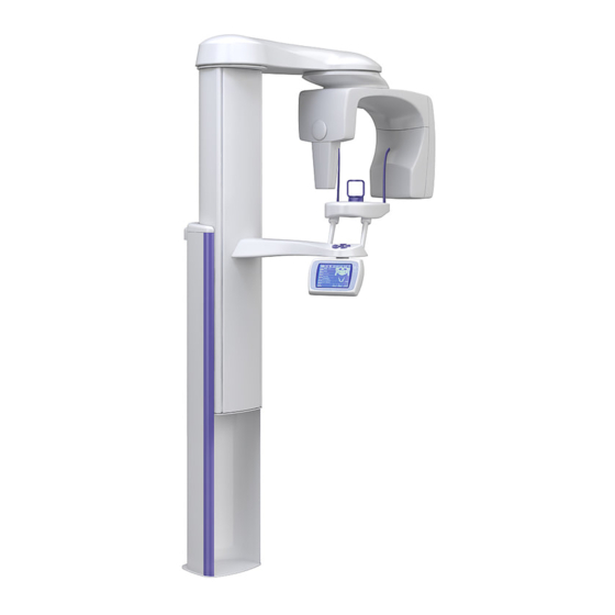
- Manuals
- Brands
- Planmeca Manuals
- Medical Equipment
- Planmeca ProMax 3D s
- User manual
-
Contents
-
Table of Contents
-
Bookmarks
Quick Links
Planmeca ProMax
®
3D s & 3D Classic
user’s manual
3D imaging
Related Manuals for Planmeca ProMax 3D s
Summary of Contents for Planmeca ProMax 3D s
-
Page 1
Planmeca ProMax ® 3D s & 3D Classic user’s manual 3D imaging… -
Page 3: Table Of Contents
Touch screen ……………………17 6.10 ProTouch desktop application ………………..20 6.11 Patient positioning controls ………………..21 PLANMECA PROMAX 3D s PROGRAMS …………….23 3D Dental ……………………..23 3D Models ……………………..23 PLANMECA PROMAX 3D CLASSIC PROGRAMS ………….. 24 3D Dental ……………………..24 3D Models ……………………..
-
Page 4
IEC 60364 — equipment is used according to the operating instructions. Planmeca pursues a policy of continual product development. Although every effort is made to produce up-to-date product documentation this publication should not be regarded as an infallible guide to current specifications. We reserve the right to make changes without prior notice. -
Page 5: Introduction
You need a PC with the Planmeca Romexis program in order to save, view and modify the images. Make sure that you are fully acquainted with the appropriate radiation protection measures and these instructions before you use the X-ray unit.
-
Page 6: Associated Documentation
User’s Manual, Original English publication: 10014593 • Technical Manual, Original English publication: 10037884 NOTE The User’s Manuals are available on Planmeca’s website. • For X-ray units, select Material bank > Manuals > Imaging. • For software products, select Material bank >…
-
Page 7: Symbols On Product Labels
(Standard ISO 7010-M002) Emergency stop (Standard IEC 60601-1) Warning; Electricity (Standard ISO 7010-W012) Electrostatic sensitive device (Standard IEC 60417) Warning; Hot surface (Standard ISO 7010-W017) General warning sign (Standard ISO 7010-W001) User’s Manual (3D Imaging) Planmeca ProMax 3D s & 3D Classic…
-
Page 8: Symbols On X-Ray Units With Detachable Power Supply Cord
Separate collection for electrical and electronic equipment (Directive 2002/96/EC WEEE) Attention, consult accompanying documents (Standard IEC 60601-1) Alternating current (Standard IEC 60417) Electrostatic sensitive device (Standard IEC 60417) Warning; Hot surface (Standard ISO 7010-W017) Planmeca ProMax 3D s & 3D Classic User’s Manual (3D Imaging)
-
Page 9: Safety Precautions
The patient positioning lights are laser lights. Do not stare into the laser beam. CAUTION Do not drop the sensor. Planmeca limited warranty does not cover damage which is due to misuse, e.g. dropping the sensor, neglect, or any cause other than ordinary use.
-
Page 10
NOTE If the X-ray system is not connected to an Uninterruptible Power Supply (UPS), switch the X-ray unit off and disconnect the PCs from the mains during lightning storms. Planmeca ProMax 3D s & 3D Classic User’s Manual (3D Imaging) -
Page 11
Contact your service technician if you notice a decrease in image quality. NOTE Contact your service technician if you have taken an exposure but the image does not appear in the Planmeca Romexis program. The last ten images can be manually imported into Romexis. NOTE Do not handle liquids near or on the X-ray unit. -
Page 12
Do not touch the metal parts in the middle of the tube head. They might be hot. NOTE FOR PROFACE SENSOR: Do not touch the glass windows. Fingerprints or other stains on the glass surface destroy image quality. Prof_6C.eps Planmeca ProMax 3D s & 3D Classic User’s Manual (3D Imaging) -
Page 13: Switching X-Ray Unit On
The on / off switch is located on the underside of the stationary column top. NOTE To prolong the lifetime of your X-ray unit, always switch the X-ray unit off when it is not in active use. User’s Manual (3D Imaging) Planmeca ProMax 3D s & 3D Classic…
-
Page 14: Main Parts
6.1 General view of X-ray system 3 & 4 X-ray unit 3D reconstruction PC Planmeca Romexis program ProTouch desktop application (optional, see section 6.10 “ProTouch desktop application” on page 20) Ethernet switch Planmeca ProMax 3D s & 3D Classic User’s Manual (3D Imaging)
-
Page 15: General View Of X-Ray Unit
Touch screen (see section 6.9 “Touch screen” on page 17) Telescopic column (see section 6.6 “Telescopic column” on page 15) 10 Stationary column 11 Emergency stop button (see section 6.8 “Emergency stop button” on page 16) User’s Manual (3D Imaging) Planmeca ProMax 3D s & 3D Classic…
-
Page 16: Sensor
6 MAIN PARTS 6.3 Sensor 3D sensor for Planmeca ProMax 3D s 3D sensor for Planmeca ProMax 3D Classic ProFace sensor for Planmeca ProMax 3D s and Planmeca ProMax 3D Classic Planmeca ProMax 3D s & 3D Classic User’s Manual (3D Imaging)
-
Page 17: Tube Head
6 MAIN PARTS 6.4 Tube head Non-rotating tube head Rotating tube head User’s Manual (3D Imaging) Planmeca ProMax 3D s & 3D Classic…
-
Page 18: Patient Supports
6 MAIN PARTS 6.5 Patient supports 6.5.1 Head supports (A or B) Adjustable head support 1. Head band 25 Temple pads for children 2. Support bars Fastening straps Support bars Planmeca ProMax 3D s & 3D Classic User’s Manual (3D Imaging)
-
Page 19: Telescopic Column
6 MAIN PARTS 6.5.2 Chin supports Chin cup Chin support Adjustable adapter 6.6 Telescopic column Telescopic column without accessory cabinet Telescopic column with accessory cabinet (three accessory boxes) User’s Manual (3D Imaging) Planmeca ProMax 3D s & 3D Classic…
-
Page 20: Exposure Switch
A help message will appear on the touch screen. Guide the patient away from the X-ray unit. Then release the emergency stop button. The X-ray unit will automatically restart. Planmeca ProMax 3D s & 3D Classic User’s Manual (3D Imaging)
-
Page 21: Touch Screen
• Program group button(s): To view all the programs that are available for a program group, select the program group button. User’s Manual (3D Imaging) Planmeca ProMax 3D s & 3D Classic…
-
Page 22
• Moving backward: To go back to a previous screen, select a previous symbol at the bottom of the screen. Planmeca ProMax 3D s & 3D Classic User’s Manual (3D Imaging) -
Page 23
Checking patient’s name and ID number: The patient’s name and ID number are shown in the top right corner of the touch screen. The patient and exposure mode have to be selected in Planmeca Romexis. • Checking DAP and CTDI values:… -
Page 24: Protouch Desktop Application
To move the control panel screen, drag it with your mouse. To close the application, click on the small red cross in the top right corner of the screen. Planmeca ProMax 3D s & 3D Classic User’s Manual (3D Imaging)
-
Page 25: Patient Positioning Controls
If something is in danger of becoming trapped, release the button immediately to stop the movement. Clear any obstruction before pressing the button again. User’s Manual (3D Imaging) Planmeca ProMax 3D s & 3D Classic…
-
Page 26
Open / close temple supports Press the temple support button to open the temple supports in 2D imaging. The temple supports can be closed by pressing the temple support button again. Planmeca ProMax 3D s & 3D Classic User’s Manual (3D Imaging) -
Page 27: Planmeca Promax 3D S Programs
3 x Ø50 x H50 mm 3 x Ø50 x H80 mm 7.2 3D Models 7.2.1 Volume size Program Ø50 mm IMPRESSION Ø50 x H40 mm PLASTER CAST Ø50 x H40 mm User’s Manual (3D Imaging) Planmeca ProMax 3D s & 3D Classic…
-
Page 28: Planmeca Promax 3D Classic Programs
* = Volume diameter can be extended to 110 mm 8.2 3D Models 8.2.1 Volume size Program Ø80 mm IMPRESSION Ø80 x H40 mm PLASTER CAST Ø80 x H40 mm Planmeca ProMax 3D s & 3D Classic User’s Manual (3D Imaging)
-
Page 29: Patient Exposure
Do not touch the glass windows. Fingerprints or other stains on the glass surface destroy image quality. Prof_6C.eps CAUTION Do not drop the sensor. Planmeca limited warranty does not cover damage which is due to misuse, e.g. dropping the sensor, neglect, or any cause other than ordinary use.
-
Page 30
NOTE For safety reasons, wait for at least ten seconds before you attach a sensor again. The blue indicator light under the locking knob has to switch off first. Planmeca ProMax 3D s & 3D Classic User’s Manual (3D Imaging) -
Page 31
Ensure that you insert the support bars the right way round. Head support A: Attaching adjustable head support If you are using the adjustable head support, slide it onto the support bars. User’s Manual (3D Imaging) Planmeca ProMax 3D s & 3D Classic… -
Page 32
50 mm (2 in.). Straps with a free length (i.e. when they are not stretched) of over 255 mm (10 in.) do not support the patient’s head firmly. Planmeca ProMax 3D s & 3D Classic User’s Manual (3D Imaging) -
Page 33
The lower the patient is positioned, the higher the image position will Use these patient supports. User’s Manual (3D Imaging) Planmeca ProMax 3D s & 3D Classic… -
Page 34
Use the highest position and a chin cup when taking exposures of the teeth area or other anatomical structures that are at this height. Teeth program Tooth program TEETH AREA: Chin cup up Planmeca ProMax 3D s & 3D Classic User’s Manual (3D Imaging) -
Page 35
Use the lowest position and a chin support under the nose when taking ear or temporomandibular joint (TMJ) exposures. Tooth program Teeth program EAR or TMJ: Chin support down Jossu 5 User’s Manual (3D Imaging) Planmeca ProMax 3D s & 3D Classic… -
Page 36: Preparing Patient
9 3D PATIENT EXPOSURE 9.1.4 Preparing Planmeca Romexis First select the patient. Then select the 3D exposure. Refer to the Planmeca Romexis User’s Manual for details on Romexis functions. 9.2 Preparing patient Ask the patient to remove any spectacles, hearing aids,…
-
Page 37: Selecting Exposure Settings
9.3.1 Selecting program Select the 3D program you wish to use. Refer to • section 7 “PLANMECA PROMAX 3D s PROGRAMS” on page 23 or • section 8 “PLANMECA PROMAX 3D CLASSIC PROGRAMS” on page 24 for details.
-
Page 38
9 3D PATIENT EXPOSURE 9.3.3 Selecting extended volume diameter NOTE This is an optional feature for Planmeca ProMax 3D Classic X-ray units. It is available for the front-most volume position in the 3D Teeth program. Use this button to select the extended volume diameter. -
Page 39
The available options depend on the selected program. NOTE In 3D Double Scan and 3D Triple Scan programs the selected area is the primary image volume. The other image volume(s) adjoin(s) the primary image volume. User’s Manual (3D Imaging) Planmeca ProMax 3D s & 3D Classic… -
Page 40
Use this button if you wish to reduce the diameter of the adjoining image volume(s). NOTE All image volumes are the same height. Planmeca ProMax 3D s & 3D Classic User’s Manual (3D Imaging) -
Page 41: Patient Positioning
• You can use fastening straps for additional head support if needed. Refer to section 9.1.2 “Attaching head support” on page 27 for details. User’s Manual (3D Imaging) Planmeca ProMax 3D s & 3D Classic…
-
Page 42: Selecting Exposure Values
The available options depend on the selected program and X-ray unit model. NOTE The exposure values will automatically change according to the selected patient size, image resolution and ULD setting. Planmeca ProMax 3D s & 3D Classic User’s Manual (3D Imaging)
-
Page 43
Factory presets for image resolution Normal mA VALUE PATIENT SIZE kV VALUE mA VALUE WITH ULD Child (XS) Small adult (S) Medium-sized adult (M) Large adult (L) Extra large adult (XL) User’s Manual (3D Imaging) Planmeca ProMax 3D s & 3D Classic… -
Page 44
Select the green check mark button. NOTE You can adjust the preset exposure values permanently as described in section 12.2.1 “Programs (2100)” on page 75. Planmeca ProMax 3D s & 3D Classic User’s Manual (3D Imaging) -
Page 45: Selecting Patient Movement Correction
9 3D PATIENT EXPOSURE 9.6 Selecting patient movement correction Use this button to select the Planmeca CALM patient movement correction function. This is an algorithm that detects patient movement during exposure and then compensates for the effects of the movement during image reconstruction.
-
Page 46: Adjusting Volume Position
Press any of the positioning controls (button or joystick). The lights will automatically switch off after two minutes. To switch them off earlier, press the positioning joystick. Planmeca ProMax 3D s & 3D Classic User’s Manual (3D Imaging)
-
Page 47
Adjustable adapter NOTE If only the upper jaw half is selected, the lower edge of the image volume is positioned 30 mm (1.2 in.) above the volume bottom light. User’s Manual (3D Imaging) Planmeca ProMax 3D s & 3D Classic… -
Page 48
(i.e. the image volume center as seen from the front) will move accordingly on your patient’s face. Left Right Right Left Positioning joystick (front light = X laser) Planmeca ProMax 3D s & 3D Classic User’s Manual (3D Imaging) -
Page 49
The side light (i.e. the image volume center as seen from the side) will move accordingly on your patient’s face. Thumb wheel (side light = Y laser) Front Back Back Positioning joystick (side light = Y laser) Front User’s Manual (3D Imaging) Planmeca ProMax 3D s & 3D Classic… -
Page 50: Taking A Scout Image Or 2D Views (Lat, Pa Or Lat-Pa)
Make sure that you have selected the correct patient and exposure mode in the Planmeca Romexis program. Select the view you wish to take. To take LAT-PA views, select both buttons (LAT and PA). Planmeca ProMax 3D s & 3D Classic User’s Manual (3D Imaging)
-
Page 51
The image is shown on the computer screen. If needed, you can readjust the volume position as shown below. • For scout images: Use the plus and minus signs that appear on the touch screen. User’s Manual (3D Imaging) Planmeca ProMax 3D s & 3D Classic… -
Page 52
9.8.2 “Moving image volume horizontally (X and Y lasers)” on page 44. Then take a new exposure as described above. Repeat the procedure until the image volume is in the correct place. Planmeca ProMax 3D s & 3D Classic User’s Manual (3D Imaging) -
Page 53: Taking A 3D Exposure
Maintain audio and visual contact with the patient and X-ray unit during exposure. If the C-arm stops moving during exposure, or moves in an erratic way, release the exposure button immediately. User’s Manual (3D Imaging) Planmeca ProMax 3D s & 3D Classic…
-
Page 54
Remove the fastening straps (if used). Release the patient from the head support by turning the adjusting knob at the top. Guide the patient away from the X-ray unit. Planmeca ProMax 3D s & 3D Classic User’s Manual (3D Imaging) -
Page 55: Face Photo
Do not use the chin cup or the fastening straps when taking 3D face photos. Select the patient and the 3D exposure as described in section 9.1.4 “Preparing Planmeca Romexis” on page 32. 10.2 Patient positioning Select the ProFace program (Special Programs >…
-
Page 56
If you wish to see the patient’s ears clearly in the photo, position the patient’s head so that the head support is at the back of the head as shown here. Ask the patient to grasp the patient handles. Planmeca ProMax 3D s & 3D Classic User’s Manual (3D Imaging) -
Page 57: Selecting Exposure Settings
(Y laser). • Select the button again if you wish to rotate the C-arm back to the original position. User’s Manual (3D Imaging) Planmeca ProMax 3D s & 3D Classic…
-
Page 58: Taking A 3D Face Photo
Ask the patient to either keep their eyes shut or to focus them on a fixed point so that the eyes are not half open in the image. Planmeca ProMax 3D s & 3D Classic User’s Manual (3D Imaging)
-
Page 59
The photo is shown on the computer screen. Release the patient from the head support by turning the adjusting knob at the top. Guide the patient away from the X-ray unit. User’s Manual (3D Imaging) Planmeca ProMax 3D s & 3D Classic… -
Page 60: Model Exposure
Calibration pin pin has to be pushed in thicker end first. The middle (part number rim has to be flush with the top edge of the calibration 10031265) cup. Planmeca ProMax 3D s & 3D Classic User’s Manual (3D Imaging)
-
Page 61
11.1.2 Selecting settings On the X-ray unit, select the program. • For impression material select 3D Models > Impression. • For plaster material select 3D Models > Plaster Cast. User’s Manual (3D Imaging) Planmeca ProMax 3D s & 3D Classic… -
Page 62
Place the calibration cup on the polystyrene disc so that the volume center lights cross in the middle of the cup. Volume center lights Calibration cup on polystyrene disc Planmeca ProMax 3D s & 3D Classic User’s Manual (3D Imaging) -
Page 63
X-ray system is getting ready for an exposure. The green lights stop flashing and stay on continuously when the X-ray system is ready for an exposure. Move to a protected area. User’s Manual (3D Imaging) Planmeca ProMax 3D s & 3D Classic… -
Page 64: Taking An Exposure Of An Impression Or Plaster Cast
Additionally, a radiation warning symbol is shown on the touch screen. In the Planmeca Romexis program, enter a name for this material and select OK. NOTE The calibration exposure values are automatically included at the beginning of the name.
-
Page 65
Select the exposure values that you used in the calibration process for this material. Refer to section 9.5.3 “Adjusting exposure values for current exposure” on page 39 if you need to adjust the preset exposure values. User’s Manual (3D Imaging) Planmeca ProMax 3D s & 3D Classic… -
Page 66
40 mm (1.6 in.). Planmeca ProMax 3D Classic 40 mm Volume center lights Impression on polystyrene disc If not yet done, select the patient in the Planmeca Romexis program. Planmeca ProMax 3D s & 3D Classic User’s Manual (3D Imaging) -
Page 67
During exposure yellow radiation warning lights illuminate on the exposure switch and on the touch screen, and you hear a radiation warning tone. Additionally, a radiation warning symbol is shown on the touch screen. User’s Manual (3D Imaging) Planmeca ProMax 3D s & 3D Classic… -
Page 68
11 3D MODEL EXPOSURE The image is shown on the computer screen. NOTE The Romexis function Model Capture creates surface models (instead of voxel data images). Planmeca ProMax 3D s & 3D Classic User’s Manual (3D Imaging) -
Page 69: Settings
About Settings that can be entered by service personnel only (password required): • Technical To return to the main screen, select the settings symbol at the top left corner. User’s Manual (3D Imaging) Planmeca ProMax 3D s & 3D Classic…
-
Page 70: User Settings
Select User > 1200 Time and Date > 1210 Set System Time and Time / Date Display Format > Time Display Format. Select the display format you wish to use. Select the green check mark button. Planmeca ProMax 3D s & 3D Classic User’s Manual (3D Imaging)
-
Page 71
Select the green check mark button. NOTE The time is set to the local time at the factory. Change the time setting to show the correct time before you start using the X-ray unit. User’s Manual (3D Imaging) Planmeca ProMax 3D s & 3D Classic… -
Page 72
Select the mode you wish to use. In demo mode you can practice or demonstrate the functions of the X-ray unit without radiation and PC connection. Select the green check mark button. Planmeca ProMax 3D s & 3D Classic User’s Manual (3D Imaging) -
Page 73
Use the minus or plus button to reduce or increase the volume. Set the volume level to 0% if you do not wish to use this function. Select the green check mark button. User’s Manual (3D Imaging) Planmeca ProMax 3D s & 3D Classic… -
Page 74
Note, however, that the automatic function works only if the exposure button is pressed and held down for the entire duration of the exposure. Select the green check mark button. Planmeca ProMax 3D s & 3D Classic User’s Manual (3D Imaging) -
Page 75
Note that the setting affects all indicator lights that are connected to your X-ray system (indicator light on the hand-held exposure switch, wall exposure switch(es) and remote exposure lamp). Select the green check mark button. User’s Manual (3D Imaging) Planmeca ProMax 3D s & 3D Classic… -
Page 76
Select User > 1400 Network Settings. Select the network settings you wish to view. Select the green check mark button. NOTE Only a service technician or local administrator may change the network settings. Planmeca ProMax 3D s & 3D Classic User’s Manual (3D Imaging) -
Page 77
Press and hold down the exposure button for the duration of the exposure. The C-arm will not move when you take a test exposure. Select the green check mark button. User’s Manual (3D Imaging) Planmeca ProMax 3D s & 3D Classic… -
Page 78
Select User > 1600 Clinic Management to view the network settings for the Planmeca Romexis Clinic Management module. NOTE Only a service technician or local administrator may change the settings. Planmeca ProMax 3D s & 3D Classic User’s Manual (3D Imaging) -
Page 79: Program Settings
Always try to minimize the radiation dose to the patient. NOTE You can restore the exposure values that have been preset at the factory (i.e. overrule your own settings) by selecting Program > 2500 Reset to Factory Defaults. User’s Manual (3D Imaging) Planmeca ProMax 3D s & 3D Classic…
-
Page 80
To manage program settings: Select Program > 2200 Program Features to manage program settings. For details on a specific setting, refer to the manual section that contains the corresponding function. Planmeca ProMax 3D s & 3D Classic User’s Manual (3D Imaging) -
Page 81
The preset exposure values for 3D patient exposures are shown in section 9.5.3 “Adjusting exposure values for current exposure” on page 39 and for 3D model exposures in section 11.1.2 “Selecting settings” on page 57. User’s Manual (3D Imaging) Planmeca ProMax 3D s & 3D Classic… -
Page 82: About Tab
X-ray unit. • To view software build information: Select About > 4100 Component Information > Show Detailed Build Info to view details about the software build. Planmeca ProMax 3D s & 3D Classic User’s Manual (3D Imaging)
-
Page 83
Select About > 4200 Archive > Exposure Statistics to view statistical data about the X-ray unit. 12.3.3 Product Registration (4300) • To register the X-ray unit on Planmeca’s website: Select About > 4300 Product Registration. Do one of the following: A QR (Quick Response) code is shown on the screen. -
Page 84: Help Messages
H144 Height movement is not possible Release the button / joystick. because one (or more) of the positioning control buttons or the positioning joystick is stuck. Planmeca ProMax 3D s & 3D Classic User’s Manual (3D Imaging)
-
Page 85
ProTouch desktop application) is not connected to the ProMax main software. H195 Request timed out while waiting for Retry or contact your service ProMax to respond. technician for help. User’s Manual (3D Imaging) Planmeca ProMax 3D s & 3D Classic… -
Page 86: Error Messages
Guide the patient away from the X-ray unit. Then clear the message by touching the green check mark. Planmeca ProMax 3D s & 3D Classic User’s Manual (3D Imaging)
-
Page 87: Cleaning And Disinfection
Wipe these parts after each patient using a mild surface disinfectant and a clean soft cloth. Use a mild cleaning solution and a clean soft cloth for cleaning stains and dirt if needed. • 3D patient supports User’s Manual (3D Imaging) Planmeca ProMax 3D s & 3D Classic…
-
Page 88
15 CLEANING AND DISINFECTION • Panoramic patient supports • Cephalometric patient supports • Patient handles Planmeca ProMax 3D s & 3D Classic User’s Manual (3D Imaging) -
Page 89: Touch Screen
They can be autoclaved up to 100 times. 15.2 Touch screen Wipe the touch screen regularly using a clean soft cloth that has been slightly dampened with water. NOTE Do not use any cleaning solutions. User’s Manual (3D Imaging) Planmeca ProMax 3D s & 3D Classic…
-
Page 90: Sensor
Do not use any cleaning solutions. 15.3.2 Other sensors Wipe the sensor surfaces regularly using a clean soft cloth that has been slightly dampened with water. NOTE Do not use any cleaning solutions. Planmeca ProMax 3D s & 3D Classic User’s Manual (3D Imaging)
-
Page 91: Other Surfaces
Wipe the other surfaces regularly using a mild cleaning solution and a clean soft cloth. NOTE FOR TOUCH SCREEN AND SENSOR(S): Refer to sections 15.2 “Touch screen” on page 85 and 15.3 “Sensor” on page 86. User’s Manual (3D Imaging) Planmeca ProMax 3D s & 3D Classic…
-
Page 92: Service
16 SERVICE 16 SERVICE The X-ray unit must be checked by a qualified Planmeca service technician once a year or after every 10 000 exposures (if this is sooner). This will guarantee patient and user safety and ensure consistent image quality.
-
Page 93: Disposal
— plastic PUR, other plastics Motors Component boards Cables, Copper, transformers steel, transformer oil X-ray tube Packing Wood, cardboard, paper, polystyrene Sensor Return sensor to Planmeca. Other parts User’s Manual (3D Imaging) Planmeca ProMax 3D s & 3D Classic…
-
Page 94: Technical Specifications
18 TECHNICAL SPECIFICATIONS 18 TECHNICAL SPECIFICATIONS 18.1 Technical data for Planmeca ProMax product family Classification Medical Device Directive 93/42/EEC (Class IIb) RoHS 2011/65/EU IEC 60601-1 Class I, type B CISPR 11 Class B IP Classification IP20 Applied parts (according to IEC 60601-1: 2012)
-
Page 95
Superior SXR 130-10-0.5 SC 1 — 14 mA ±10% Pan / SmartPan 1 — 16 mA ±10% Scanning ceph 1 — 16 mA ±10% Planmeca ProCeph 16 mA ±10% mAs range User’s Manual (3D Imaging) Planmeca ProMax 3D s & 3D Classic… -
Page 96
2D / 3D s / 3D Classic: 1.2 — 1.5 2D tomography: 1.5 3D Plus / 3D Mid: 1.4 SmartPan 3D s / 3D Classic: 1.27 3D Plus / 3D Mid / 3D Max: 1.4 Ceph 1.13 Planmeca ProMax 3D s & 3D Classic User’s Manual (3D Imaging) -
Page 97
3D Plus / 3D Mid 141 kg (311 lb) 3D Max 139 kg (306 lb) Scanning ceph 26 kg (57 lb) Planmeca ProCeph 20 kg (44 lb) Environmental requirements User’s Manual (3D Imaging) Planmeca ProMax 3D s & 3D Classic… -
Page 98
130 x 130 mm (5.12 x 5.12 in.) 3D Mid: 146 x 146 mm (5.74 x 5.74 in.) 3D Max: 193 x 242 mm (7.6 x 9.5 in.) SmartPan: Flat panel pixel size 127 m Planmeca ProMax 3D s & 3D Classic User’s Manual (3D Imaging) -
Page 99: Original Manufacturer
(no windows in the room) No green objects next to X-ray 18.2 Original manufacturer PLANMECA Oy, Asentajankatu 6, FIN-00880 Helsinki, FINLAND Phone: +358 20 7795 500, Fax: +358 20 7795 555, www.planmeca.com User’s Manual (3D Imaging) Planmeca ProMax 3D s & 3D Classic…
-
Page 102
Planmeca Oy | Asentajankatu 6 | 00880 Helsinki | Finland tel. +358 20 7795 500 | fax +358 20 7795 555 | sales@planmeca.com | www.planmeca.com…
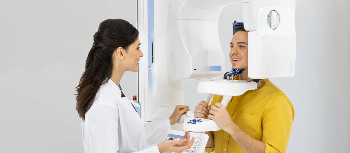
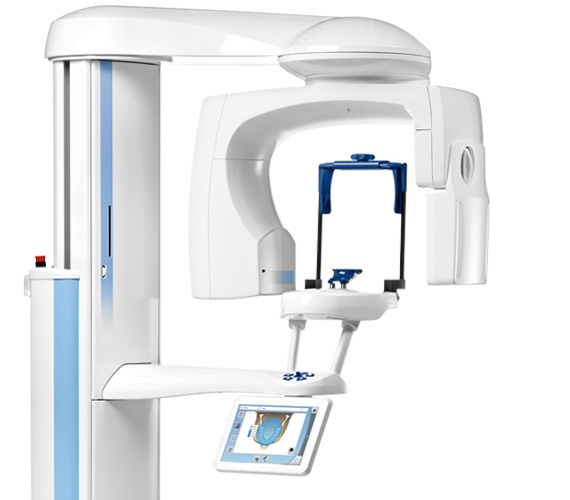
Охватывает всю область расположения зубов
Рентген Planmeca Pro Max 3D Classic предназначен для получения полной информации об анатомии Вашего пациента в мельчайших подробностях. Этот «умный» и многофункциональный рентгеновский аппарат обеспечит цифровые панорамные, цефалометрические и 3D изображения, а также 3D-фотографии и 3D-сканирование моделей.
Planmeca ProMax 3D – идеальная установка для получения трёхмерных изображений нижней и верхней челюсти, поэтому она отлично подходит для широкого спектра применения в имплантологии, челюстно-лицевой хирургии, пародонтологии, ортодонтии, исследовании височно-нижнечелюстного сустава, исследовании пазух и пр. Данная гибридная установка объединяет в себе все функции классического ортопантомографа и современные 3D-технологии для получения объёмных изображений. Данная гибридная установка объединяет в себе все функции классического ортопантомографа и современные 3D-технологии для получения объёмных изображений.
— Конусно-лучевая технология получения изображений.
— Установка построена на платформе Planmeca ProMax, использующей технологию программируемого набора высокоточных движений SCARA3.
— Малое время облучения (от 3 с), быстрое сканирование (18 с), быстрая реконструкция изображений (от 15 с).
— Система панорамной съёмки SmartPan — получение панорамных снимков отличного качества с помощью 3D-датчика, возможность выбора необходимого слоя из 9-ти представленных.
— Возможности дальнейшего обновления: цефалостат, 3D-сканер лица Planmeca Proface 3D.
Размеры исследуемых объёмных областей:
— 140 x 105 x 130 мм (сшитый);
— 80 х 80 мм (для детей — 68 х 68 мм);
— 80 х 50 мм (для детей — 68 х 42 мм);

— 40 х 80 мм (для детей — 34 х 68 мм);
— 40х50 мм (для детей — 34х42 мм).
Основные панорамные программы (в комплекте):
— Стандартная панорама взрослого,
— Стандартная панорама ребенка,
— Боковой двойной ВНЧС,
— Двойной задне-передний ВНЧС,
— Задне-передний синус (прямой слой).
Дополнительная панорамная программа (под заказ): вертикальное сегментирование для панорамной съемки.
Дополнительные панорамные программы для специализированной диагностики (под заказ):
— улучшенные межпроксимальные и ортогональные рентгенограммы,
— прикусные рентгенограммы,
— расширенные программы для исследования пазух и ВНЧС,
— поперечные сечения.
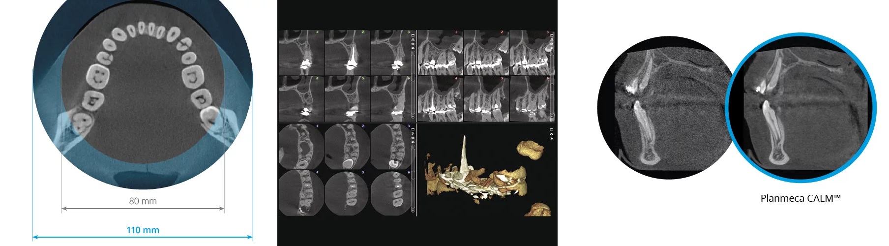
Cone Beam Volumetric Tomography (CBVT)
Рентгеновские томографы серии Planmeca ProMax 3D, для получения объемных изображений, используют технологию Конусно-лучевой компьютерной томографии (CBVT). Данная технология позволяет сформировать объемное изображение из большого числа 2D проекций, полученных с разных ракурсов. Полученные изображения можно просматривать с помощью специального программного обеспечения Romexis под любым углом, в том числе, осевом, коронарном, сагиттальном и поперечных сечениях.
3D изображения:
— Стандартный режим: размер вокселя 200 мкм.
— Режим высокой плотности записи: размер вокселя 150 мкм.
— Режим с низкой дозой облучения: размер вокселя 400 мкм.
— Режим высокого разрешения: размер вокселя 100 мкм.
— Скинирование слепка (опция): размер вокселя 150 мкм.
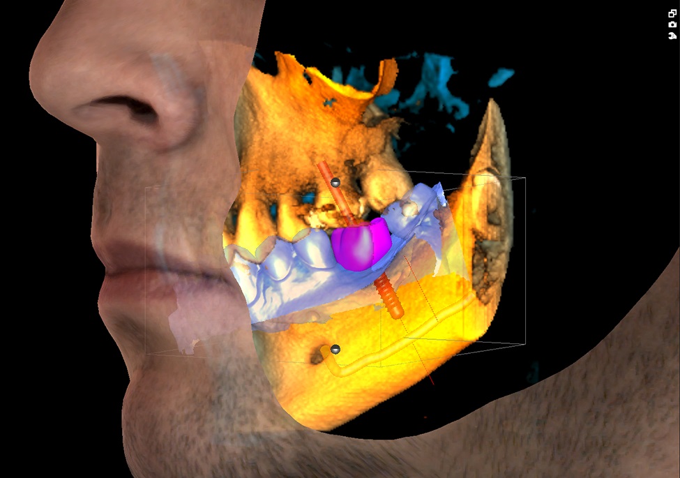
Новейшие технологии:
— Передовая конусно-лучевая технология получения изображений.
— Использование новейшего алгоритма реконструкции на основе обратной проекции Feldkamp.
— Интеллектуальная система удаления шума Planmeca AINO™ и алгоритмы удаления артефактов Planmeca АРА ™
— Уникальная система программируемых высокоточных движений съемочного узла SCARA3, для более точного позиционирования области исследования.
— Запатентованная система панорамной съёмки SmartPan для получения панорамных снимков высокого качества с помощью 3D-датчика, с возможностью выбора необходимого слоя из 9-ти представленных.
— Передовое программное обеспечение PlanmecaRomexis, совместимое с MacOsи Windows.
Удобство работы:
— Быстрое позиционирование пациента, благодаря открытой конструкции.
— Комфортное обследование пациентов в инвалидных креслах или пациентов с чувством клаустрофобии, благодаря боковому доступу.
— Удобная панель управления с интуитивно понятным интерфейсом на русском языке.
— Наличие предустановленных программ экспозиции для разных типов исследований, поможет сэкономить ваше время.
— Наличие функции предварительных снимков для более четкого позиционирования пациента.
— Минимальное время экспозиции и реконструкции изображений.
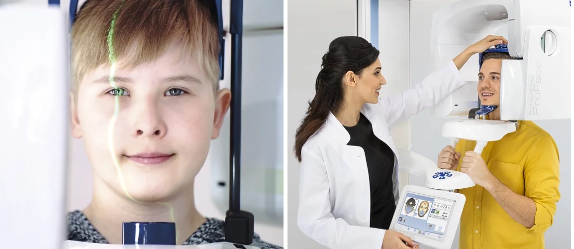
Минимальная доза облучения:
— Импульсный режим съемки позволяет максимально снизить дозу облучения пациента.
— Подбор оптимального размера облучаемой области с помощью встроенного коллиматора.
— Наличие специального режима с ультра низкой дозой облучения пациентов, для педиатрических исследований.
Модульная конструкция:
— Возможность дальнейшего дооснащения: цефалометрической приставкой, 3D-сканером лица Planmeca Proface 3D.
— Благодаря модульному программному обеспечению вы с легкостью получаете доступ к необходимым инструментам визуализации и планирования лечения.
— Съемная цветная вставка поможет гармонично вписать оборудование в интерьер вашей клиники.
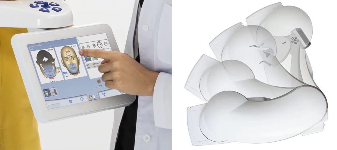
Методы визуализации для любой задачи
Как и все остальные 3D рентгеновские аппараты нашей компании, Planmeca ProMax 3D Classic поддерживает широкий спектр методов визуализации и специализированных протоколов, разработанных для различных профессиональных нужд.
Гибкая технология SCARA
Наши системы визуализации являются исключительными благодаря использованию запатентованной технологии SCARA: роботизированной руки, которая может производить любую требуемую траекторию – без каких-либо ограничений.
Программное обеспечение визуализации «все-в-одном»
Программное обеспечение Planmeca Romexis® для визуализации поддерживает все методы 2D и 3D визуализации, а также процесс CAD/CAM. Программа предлагает широкий спектр инструментов для стоматологических клиник любого размера.

Download Operation & user’s manual of Planmeca Planmeca ProMax 3D Classic Dental equipment, Medical Equipment for Free or View it Online on All-Guides.com.

1

2
3
4
5
6
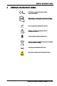
7
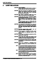
8
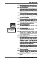
9
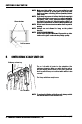
10
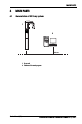
11
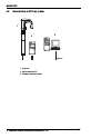
12
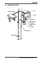
13
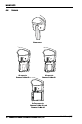
14
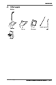
15
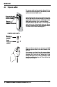
16
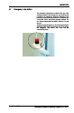
17
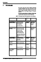
18
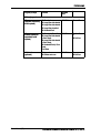
19
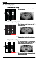
20
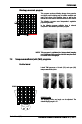
21
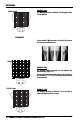
22
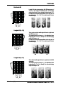
23
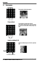
24
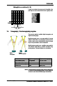
25
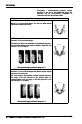
26
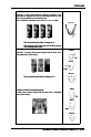
27
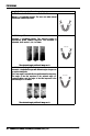
28

29
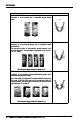
30
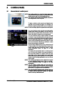
31
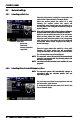
32
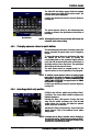
33
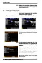
34
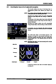
35
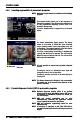
36
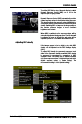
37
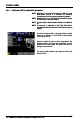
38
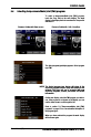
39
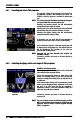
40
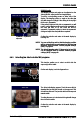
41
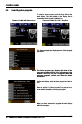
42
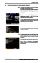
43
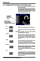
44
45
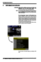
46
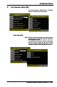
47
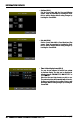
48
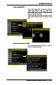
49
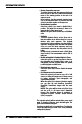
50
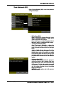
51
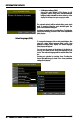
52
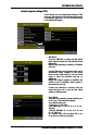
53
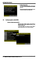
54
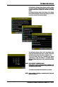
55
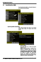
56
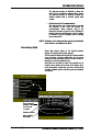
57

58
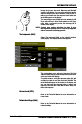
59
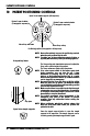
60
61
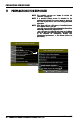
62
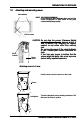
63
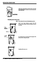
64
65
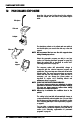
66
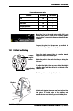
67
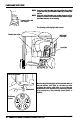
68
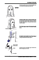
69
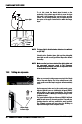
70
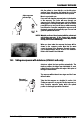
71
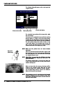
72
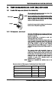
73
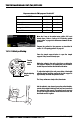
74
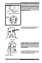
75
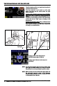
76
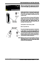
77
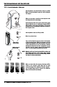
78
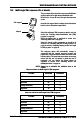
79
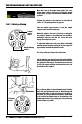
80
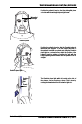
81
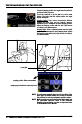
82
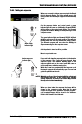
83
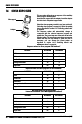
84
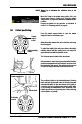
85
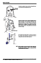
86
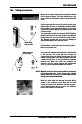
87
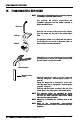
88
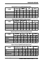
89
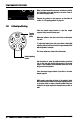
90
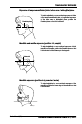
91
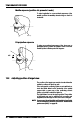
92
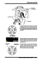
93
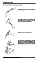
94
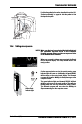
95
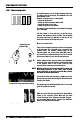
96
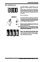
97
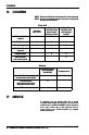
98
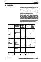
99
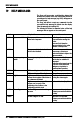
100
101
102
103
104
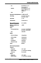
105
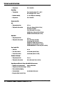
106
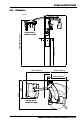
107
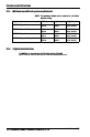
108

109
110