-
Contents
-
Table of Contents
-
Bookmarks
Quick Links
Plena Voice Alarm System
Installation and User Instructions
en
Voice Alarm System
Related Manuals for Bosch Plena
Summary of Contents for Bosch Plena
-
Page 1
Plena Voice Alarm System Installation and User Instructions Voice Alarm System… -
Page 3: Important Safeguards
Plena Voice Alarm System | Installation and User Instructions | Important Safeguards en | 3 Important Safeguards Prior to installing or operating this product, always read the Important Safety Instructions which are available as a separate document (9922 141 7014x). These instructions are supplied together with all equipment that can be connected to the mains.
-
Page 4: Important Notices
Plena Voice Alarm System | Installation and User Instructions | Important Notices en | 4 Important Notices When using routers, keypads or more than one call station, configure the controller using the supplied software. Use shielded cable (Cat-5) between the routers and the controller.
-
Page 5: Table Of Contents
Plena Voice Alarm System | Installation and User Instructions | Table of Contents en | 5 Table of Contents Important Safeguards …………………………3 Important Notices …………………………..4 Table of Contents …………………………..5 Section 1 — Introduction ………………………….9 1. About this manual …………………………10 Purpose ………………………………
-
Page 6
Plena Voice Alarm System | Installation and User Instructions | Table of Contents en | 6 8. LBB1957/00 Call Station Keypad …………………….. 52 Controls, connectors and indicators ……………………..52 Installation ………………………………53 Technical data …………………………….53 9. LBB1996/00 Voice Alarm Remote Control ………………….54 Controls, connectors and indicators …………………….. -
Page 7
Plena Voice Alarm System | Installation and User Instructions | Table of Contents en | 7 18. Supervision ……………………………. 77 18.1 Introduction ……………………………… 77 18.2 Processor reset …………………………….77 18.3 Network ………………………………77 18.4 Power amplifiers …………………………….. 77 18.5 Ground short …………………………….78 18.6 Emergency trigger inputs ………………………… -
Page 8
Plena Voice Alarm System | Installation and User Instructions | Table of Contents en | 8 27.3 Acknowledge the emergency state ……………………..91 27.4 Exit the emergency state …………………………92 27.5 Distribute live speech …………………………..92 28. Fault state …………………………….95 28.1 Introduction ……………………………… -
Page 9: Section 1 — Introduction
Plena Voice Alarm System | Installation and User Instructions | Introduction en | 9 Section 1 — Introduction Bosch Security Systems | 2006-06 | 9922 141 10377 en…
-
Page 10: About This Manual
Plena Voice Alarm System | Installation and User Instructions | Introduction en | 10 About this manual Signs Except for note alerts, the nature of the effect that can be caused when the alert is not observed, is indicated 1. 1 Purpose using a sign.
-
Page 11: Conversion Tables
Plena Voice Alarm System | Installation and User Instructions | Introduction en | 11 Conversion tables In this manual, SI units are used to express lengths, masses, temperatures etc.. These can be converted to non-metric units using the information provided below.
-
Page 12: System Overview
Plena Voice Alarm System | Installation and User Instructions | Introduction en | 12 System Overview 2.4.1 Praesideo It is possible to combine the Plena Voice Alarm System with a Praesideo digital public address and emergency 2. 1 Voice Alarm System sound system.
-
Page 13: Voice Alarm Router
Plena Voice Alarm System | Installation and User Instructions | Introduction en | 13 Voice alarm router 2.5.2 Hand-held microphone The voice alarm controller is equipped with a hand-held 2.6.1 Introduction microphone, which can be used to make emergency calls.
-
Page 14: Call Station
Plena Voice Alarm System | Installation and User Instructions | Introduction en | 14 2.6.4 External power amplifiers 2.7.2 Buttons The voice alarm router does not have an internal power Each call station has zone select buttons and a amplifier. When the power that is supplied by the voice push-to-talk (PTT) button.
-
Page 15: Application Examples
Plena Voice Alarm System | Installation and User Instructions | Introduction en | 15 Application examples 3.1.4 Power requirements The system controller features a built-in 240 W power amplifier, making it possible to drive up to 40 3. 1 Schools loudspeakers with a power handling capacity of 6 W each.
-
Page 16
Plena Voice Alarm System | Installation and User Instructions | Introduction en | 16 Z25-30 Z19-24 Z13-18 Z7-12 Z1-6 LBB1930/00 LBB1992/00 LBB1957/00 LBB1956/00 LBB1990/00 LBB1996/00 LBB1997/00 figure 3. 1 : Example of a school Bosch Security Systems | 2006-06 | 9922 141 10377 en… -
Page 17: Swimming Pool
Plena Voice Alarm System | Installation and User Instructions | Introduction en | 17 Swimming pool 3.2.4 Power requirements The system controller has a built-in 240 W power 3.2.1 Introduction amplifier, making it possible to drive up to 40 Swimming pools and other indoor sports and…
-
Page 18
Plena Voice Alarm System | Installation and User Instructions | Introduction en | 18 Z1-5 LBB1930/00 PLN-DVDT LBB1957/00 LBB1956/00 LBB1990/00 LBB1996/00 figure 3.2: Example of a swimming pool Bosch Security Systems | 2006-06 | 9922 141 10377 en… -
Page 19: Shopping Mall
Plena Voice Alarm System | Installation and User Instructions | Introduction en | 19 Shopping mall 3.3.4 Power requirements Each zone will have varying power requirements, 3.3.1 Introduction ranging from small shops with a single loudspeaker to Shopping malls are typical example of applications with…
-
Page 20
Plena Voice Alarm System | Installation and User Instructions | Introduction en | 20 Z49-54 Z43-48 Z37-42 Z31-36 Z25-30 Z19-24 LBB1938/00 Z13-18 Z7-12 Z1-6 LBB1935/00 LBB1935/00 LBB1992/00 PLN-DVDT LBB1957/00 LBB1956/00 LBB1990/00 LBB1996/00 LBB1995/00 LBB1997/00 figure 3.3: Example of a shopping mall… -
Page 21: Hotel
Plena Voice Alarm System | Installation and User Instructions | Introduction en | 21 Hotel 3.4.4 Power requirements The system controller features a built-in 240 W power 3.4.1 Introduction amplifier, able to drive up to 40 loudspeakers (6 W). Smaller hotels are typical examples of applications with…
-
Page 22
Plena Voice Alarm System | Installation and User Instructions | Introduction en | 22 LBB1938/00 Z7-12 Z1-6 LBB1935/00 LBB1992/00 PLN-DVDT LBB1957/00 LBB1990/00 LBB1956/00 LBB1997/00 LBB1996/00 figure 3.4: Example of a hotel Bosch Security Systems | 2006-06 | 9922 141 10377 en… -
Page 23: Calls And Priorities
Plena Voice Alarm System | Installation and User Instructions | Introduction en | 23 Calls and priorities Business call A business call is a call that is made when the system is in the normal state. Business calls always have a priority 4.
-
Page 24
Plena Voice Alarm System | Installation and User Instructions | Introduction en | 24 Intentionally left blank. Bosch Security Systems | 2006-06 | 9922 141 10377 en… -
Page 25: Section 2 — Equipment
Plena Voice Alarm System | Installation and User Instructions | Equipment en | 25 Section 2 — Equipment Bosch Security Systems | 2006-06 | 9922 141 10377 en…
-
Page 26: Lbb1990/00 Voice Alarm Controller
Plena Voice Alarm System | Installation and User Instructions | Equipment en | 26 LBB1990/00 Voice Alarm 6 BGM zone selectors — Six buttons to select the zones to which the BGM is distributed (see 25). Each Controller button has a green LED and a rotary knob. The six green LEDs indicate the zones to which BGM is distributed.
-
Page 27
Plena Voice Alarm System | Installation and User Instructions | Equipment en | 27 Plena Voice Alarm Controller Fault Indicators Disabled 0 dB Alarm Fault Processor reset Mains Zone1 Battery -6dB Network Zone2 Message Call/EMG Zone3 Zone select -20dB Music/Spare… -
Page 28
Plena Voice Alarm System | Installation and User Instructions | Equipment en | 28 22 Call station sockets — Two redundant RJ45 36 Monitoring speaker volume control — A rotary sockets to connect call stations (LBB1956/00) to the knob to set the volume of the monitoring voice alarm controller (see section 5.3.2). -
Page 29: Installation
Plena Voice Alarm System | Installation and User Instructions | Equipment en | 29 Installation 5.3.2 Call station The voice alarm controller is suitable for table-top and The voice alarm controller has 2 sockets for LBB1956/00 Call Stations. Use Cat-5 Ethernet cables 19-inch rack-mounting installation.
-
Page 30: Voice Alarm Routers
Plena Voice Alarm System | Installation and User Instructions | Equipment en | 30 5.3.3 Voice alarm routers 5.3.4 External power amplifier The voice alarm controller has 1 socket for LBB1992/00 The voice alarm controller has 1 external power Voice Alarm Routers. Use shielded Cat-5 Ethernet…
-
Page 31: Remote Controls
Plena Voice Alarm System | Installation and User Instructions | Equipment en | 31 5.3.5 Remote controls 5.3.6 Loudspeakers The voice alarm controller has 2 sockets for remote The voice alarm controller has 6 zone outputs controls. Use shielded Cat-5 Ethernet cables with RJ45 (Z1 to Z6).
-
Page 32
Plena Voice Alarm System | Installation and User Instructions | Equipment en | 32 5.3.7 Volume overrides If it is necessary to detect the removal or failure of a single loudspeaker, the following is advised: The voice alarm controller has 6 override outputs; 1 for •… -
Page 33
Plena Voice Alarm System | Installation and User Instructions | Equipment en | 33 Internally, the positive override pins (Z+) are all connected to either the NC or the NO contact of the Volume Override output (see figure 5.10). The negative override pins (Z-) are all connected to earth. -
Page 34
Plena Voice Alarm System | Installation and User Instructions | Equipment en | 34 See figure 5.11, situation I for an example of a fail-safe See figure 5.11, situation II for an example of a 4-wire volume override: power-saving 4-wire volume override: •… -
Page 35
Plena Voice Alarm System | Installation and User Instructions | Equipment en | 35 5.3.8 Line output To create a 3-wire volume override, see figure 5.12: The voice alarm controller has 1 line output (see figure 5.13). This output has a double cinch socket. Both cinch… -
Page 36
Plena Voice Alarm System | Installation and User Instructions | Equipment en | 36 5.3.9 Mic/line input with VOX The input automatically starts a business or emergency functionality call if the input is higher than -20 dB (100 mV for line and 100 µV for microphone inputs) or if the VOX… -
Page 37: Bgm Inputs
Plena Voice Alarm System | Installation and User Instructions | Equipment en | 37 5.3.10 BGM inputs 5.3.11 Status output contacts The voice alarm controller has 2 BGM inputs (see figure The voice alarm controller has 3 status output contacts 5.16 and table 5.1).
-
Page 38
Plena Voice Alarm System | Installation and User Instructions | Equipment en | 38 5.3.12 Power 2 Put the correct type of fuse in the voice alarm controller (see table 5.3). 5.3. 1 2. 1 Introduction The voice alarm controller has the following power… -
Page 39
Plena Voice Alarm System | Installation and User Instructions | Equipment en | 39 5.3. 1 2.3 Back-up power The voice alarm controller has a 24 V(DC) input to connect a back-up power supply (e.g. a battery) which powers the system if the mains power is not available. -
Page 40
Plena Voice Alarm System | Installation and User Instructions | Equipment en | 40 5.3.13 Trigger inputs 5.3. 1 3.3 Business trigger inputs The lower part of the terminal block (see figure 5.22) contains the business trigger inputs. The business trigger 5.3. -
Page 41: Technical Data
Plena Voice Alarm System | Installation and User Instructions | Equipment en | 41 Technical data 5.4.2 Message manager Data format: 5.4.1 Electrical WAV-file, 16-bit PCM, mono Mains voltage: Supported sample rates (fs): 230/115 V(AC), ± 10%, 50/60 Hz 24 kHz, 22.05 kHz, 16 kHz, Mains current: 12 kHz, 11.025 kHz, 8 kHz…
-
Page 42
Plena Voice Alarm System | Installation and User Instructions | Equipment en | 42 5.4.4 Interconnection 5.4.8 Trigger inputs/24 V DC out Call Station (LBB1956/00): Trigger voltage: RJ45 sockets, CAN bus < 24 V max. 8 call stations Type: Voice Alarm Router (LBB1992/00):… -
Page 43
Plena Voice Alarm System | Installation and User Instructions | Equipment en | 43 5.4.13 Environmental conditions Operating temperature range: -10 to +55 °C Storage temperature range: -40 to +70 °C Relative humidity: < 95% 5.4.14 General EMC emission: According to EN55103-1… -
Page 44: Lbb1992/00 Voice Alarm Router
Plena Voice Alarm System | Installation and User Instructions | Equipment en | 44 LBB1992/00 Voice Alarm 5 Zone outputs — Six zone outputs to connect loudspeakers to the voice alarm router. Each zone Router output consists of two loudspeaker line outputs (see section 6.3.2).
-
Page 45
Plena Voice Alarm System | Installation and User Instructions | Equipment en | 45 Plena Voice Alarm Router Fault Indicators Alarm 0 dB Processor reset Zone1 Network Mains Zone2 -6dB Call/EMG Zone3 -20dB Music/Spare Battery Zone4 Ground short Zone5 Zone select… -
Page 46: Installation
Plena Voice Alarm System | Installation and User Instructions | Equipment en | 46 Installation 6.3.5 External power amplifiers The voice alarm router is suitable for table-top and The voice alarm router has 2 external power amplifier outputs (line level, 1 V) and 1 external power amplifier 19-inch rack mounting installation.
-
Page 47
Plena Voice Alarm System | Installation and User Instructions | Equipment en | 47 6.3.6 Power See figure 6.3 for information about connecting external power amplifier 2 to a voice alarm router. The procedure for connecting a voice alarm router to… -
Page 48: Technical Data
Plena Voice Alarm System | Installation and User Instructions | Equipment en | 48 Technical data 6.4.4 Overrides Type: 6.4.1 Electrical 3-wire or 4-wire on screw terminals Mains voltage: Voltage: 230/115 V(AC), ± 10%, 50/60 Hz 24 V(DC) for 4-wire, if selected…
-
Page 49: Lbb1956/00 Call Station
Plena Voice Alarm System | Installation and User Instructions | Equipment en | 49 LBB1956/00 Call Station 6 Keypad connector — A connector to connect call station keypads (LBB1957/00) to the call station. 7 Configuration settings — A set of DIP switches to 7.
-
Page 50: External Connections
Plena Voice Alarm System | Installation and User Instructions | Equipment en | 50 External connections 7.2.1 Voice alarm controller Connect the call station to the voice alarm controller (see section 5.3.2). 7.2.2 Power supply If the cable between the voice alarm controller or the previous call station is longer than 100 m, the call station must be connected to a 24 V(DC) power source.
-
Page 51: Technical Data
Plena Voice Alarm System | Installation and User Instructions | Equipment en | 51 Technical data 7.3.3 Interconnection Type: 7.3.1 Electrical 2x redundant RJ45 sockets to connect the call station Voltage range: to the voice alarm controller with Cat-5 Ethernet 24 V(DC), +20%/-10%, supplied by LBB1990/00 or cables.
-
Page 52: Lbb1957/00 Call Station Keypad
Plena Voice Alarm System | Installation and User Instructions | Equipment en | 52 LBB1957/00 Call Station Keypad 8. 1 Controls, connectors and indicators See figure 8.1 for an overview of the controls, indicators and connectors on the call station keypad:…
-
Page 53: Installation
Plena Voice Alarm System | Installation and User Instructions | Equipment en | 53 Installation Call station keypads can be connected to call stations (LBB1956/00) or to other call station keypads (see section figure 8.2). figure 8.2: Connecting call station keypads…
-
Page 54: Lbb1996/00 Voice Alarm Remote Control
Plena Voice Alarm System | Installation and User Instructions | Equipment en | 54 LBB1996/00 Voice Alarm 6 BGM zone selectors — Six buttons to select the zones to which the BGM is distributed (see 25). Each Remote Control button has a green LED. The six green LEDs indicate the zones to which BGM is distributed.
-
Page 55
Plena Voice Alarm System | Installation and User Instructions | Equipment en | 55 Plena Voice Alarm Remote Control Fault Indicators Disabled 0 dB Alarm Fault Processor reset Mains Zone1 Battery -6dB Network Zone2 Message Call/EMG Zone3 Zone select -20dB… -
Page 56: Installation
Plena Voice Alarm System | Installation and User Instructions | Equipment en | 56 External connections 22 Monitoring speaker volume control — A rotary knob to set the volume of the monitoring 9.3.1 Voice alarm controller loudspeaker. 23 Trigger outputs — Three general purpose trigger Connect the remote control panel to the voice alarm outputs.
-
Page 57: Technical Data
Plena Voice Alarm System | Installation and User Instructions | Equipment en | 57 9.3.3 Status output contacts The remote control panel has 3 status output contacts to indicate the current system state. The procedure for connecting the status outputs is the same as the procedure for connecting status outputs to the voice alarm controller (see section 5.3.11).
-
Page 58: Lbb1998/00 Voice Alarm Remote Control Kit
Plena Voice Alarm System | Installation and User Instructions | Equipment en | 58 LBB1998/00 Voice Alarm Remote Control Kit 10. 1 Introduction With the LBB1998/00 Voice Alarm Remote Control Kit, it is possible to make customized remote controls that can be connected to the voice alarm controller. The remote control kit provides the same functionality as the LBB1996/00 Voice Alarm Remote Control.
-
Page 59: External Connections
Plena Voice Alarm System | Installation and User Instructions | Equipment en | 59 10.4 External connections 10.4.4 Relays To the LEDS/LAMPS connectors on the front panel of 10.4.1 Rear panel the remote control kit, relays can be connected (see The rear panel of the remote control kit has the same figure 10.4).
-
Page 60: Lbb1997/00 Remote Control Extension
Plena Voice Alarm System | Installation and User Instructions | Equipment en | 60 LBB1997/00 Remote 2 Fault indicators — Eight yellow system fault LEDs (Processor reset, Network, Call/EMG, Music/Spare, Control Extension Ground short, Input, Mains, Battery) and twelve yellow loudspeaker line fault LEDs. Fault indication is only possible if supervision is enabled (see section 11.
-
Page 61: Installation
Plena Voice Alarm System | Installation and User Instructions | Equipment en | 61 11.3.2 Status output contacts 5 Ground — A connection to electrically ground the remote control extension. The remote control extension has 1 status output 6 Firmware upgrade connector — An RS232 contacts to indicate the current system state.
-
Page 62: Lbb1999/00 Remote Control Extension Kit
Plena Voice Alarm System | Installation and User Instructions | Equipment en | 62 LBB1999/00 Remote Control Extension Kit 12. 1 Introduction With the LBB1999/00 Voice Alarm Control Extension Kit, it is possible to make customized remote control extensions that can be connected to a remote control (LBB1995/00, LBB1996/00, LBB1998/00).
-
Page 63: External Connections
Plena Voice Alarm System | Installation and User Instructions | Equipment en | 63 12.4 External connections 12.4.1 Rear panel The rear panel of the remote control extension kit has the same connectors and controls as the rear panel of the LBB1997/00 Voice Alarm Control Extension.
-
Page 64: Lbb1995/00 Fireman’s Panel
Plena Voice Alarm System | Installation and User Instructions | Equipment en | 64 LBB1995/00 Fireman’s 10 Ground — A connection to electrically ground the fireman’s panel. Panel 11 Firmware upgrade connector — An RS232 connector to connect a PC to upgrade the firmware of the fireman’s panel.
-
Page 65
Plena Voice Alarm System | Installation and User Instructions | Equipment en | 65 2 3 4 5 6 7 Plena Fireman’s Panel Alarm Call Emergency Message Fault Indicators Disable 0 dB Processor reset Zone1 -6dB Network Call/EMG -20dB Zone2… -
Page 66: External Connections
Plena Voice Alarm System | Installation and User Instructions | Equipment en | 66 13.2 External connections 13.2.1 Voice alarm controller Connect the fireman’s panel to the voice alarm controller (see section 5.3.5). 13.2.2 Remote control extensions The remote controller has 1 socket for remote control extensions (LBB1997/00, LBB1999/00).
-
Page 67: End Of Line Detection
Plena Voice Alarm System | Installation and User Instructions | Equipment en | 67 End of line detection • All inputs to a VAC or router that have an EOL input must be normally closed inputs. The EOL board operates with a normally closed output and 14.
-
Page 68: Installation Of A Single Eol
Plena Voice Alarm System | Installation and User Instructions | Equipment en | 68 14.3.1 Installation of a single EOL 14.3.2 Installation of multiple EOLs in a daisy-chain 1 Connect the two cables at the end of the 100 V…
-
Page 69
Plena Voice Alarm System | Installation and User Instructions | Equipment en | 69 First EOL board Last EOL board figure 14.3: Trigger input indication 5 In the configuration program, set the Action Programming for the relevant input to Fault and EOL. -
Page 70: Technical Data
Plena Voice Alarm System | Installation and User Instructions | Equipment en | 70 14.4 Technical data Input level: 100 V rms @ program 20 Hz — 20 kHz Pilot input level: 5 V — 50 V @ 20 kHz ± 20% Minimum trigger level: 3.5 V…
-
Page 71: Dummy Load
Plena Voice Alarm System | Installation and User Instructions | Equipment en | 71 Dummy load Note 15. 1 Introduction In some loudspeakers only one mounting stud is The Dummy Load has these functions: available as the studs are too far apart.
-
Page 72
Plena Voice Alarm System | Installation and User Instructions | Equipment en | 72 Intentionally left blank. Bosch Security Systems | 2006-06 | 9922 141 10377 en… -
Page 73: Section 3 — Configuration
Plena Voice Alarm System | Installation and User Instructions | Configuration en | 73 Section 3 — Configuration Bosch Security Systems | 2006-06 | 9922 141 10377 en…
-
Page 74: Introduction
Plena Voice Alarm System | Installation and User Instructions | Configuration en | 74 Introduction A number of functions of the Plena Voice Alarm System is hardware configured using, for example, DIP switches and volume controls. Other parts of the system must be software configured using the Plena Voice Alarm System configuration software.
-
Page 75: System Settings
Plena Voice Alarm System | Installation and User Instructions | Configuration en | 75 System settings 17.2 Monitor If the Monitor switch (see figure 17.1) is in the ON position, the internal monitoring loudspeaker of the 17. 1 Introduction voice alarm controller is switched on. The volume of the…
-
Page 76: Supervision
Plena Voice Alarm System | Installation and User Instructions | Configuration en | 76 17.4 Supervision 17.5.3 2-channel mode If the Supervision switch (see figure 17.1) is in the ON 17.5.3. 1 Voice alarm controller In the 2-channel mode, the BGM is amplified by the position, supervision is enabled.
-
Page 77: Supervision
Plena Voice Alarm System | Installation and User Instructions | Configuration en | 77 Supervision 18.2 Processor reset 18.2.1 Watchdog 18. 1 Introduction If supervision is enabled (see section 18.1), the processor of the voice alarm controller is supervised by a If the Supervision switch (see figure 17.1) is in the ON…
-
Page 78: Ground Short
Plena Voice Alarm System | Installation and User Instructions | Configuration en | 78 18.5 Ground short 18. 1 0 Emergency microphone If supervision is enabled and ground short supervision is If supervision is enabled and emergency microphone switched on (see section 18.1), the system can supervision is switched on (see section 18.1), the audio…
-
Page 79
Plena Voice Alarm System | Installation and User Instructions | Configuration en | 79 18.11.3 Short-circuit supervision If line supervision is switched on, the voice alarm controller continuously monitors all loudspeaker lines in the system for short-circuits. If a short-circuit is detected, the line output of the short- circuited line is isolated and shut down within 200 ms. -
Page 80: Voice Alarm Controller
Plena Voice Alarm System | Installation and User Instructions | Configuration en | 80 Voice alarm controller The volume of the mic/line input with VOX functionality is set with the VOX volume control (see figure 19.4). 19. 1 VOX configuration 19.1.1 Introduction…
-
Page 81: Voice Alarm Router
Plena Voice Alarm System | Installation and User Instructions | Configuration en | 81 Voice alarm router 20. 1 Introduction The voice alarm routers are configured using an ID selector and a DIP switch (see figure 20.1). Router Termination Firmware upgrade 1…9…
-
Page 82: Call Station
Plena Voice Alarm System | Installation and User Instructions | Configuration en | 82 Call station 21.3 Sensitivity The sensitivity of the call station is set using switches 5 and 6 (see table 21.2). 21. 1 Introduction The call stations are configured using the DIP switch at table 21.2: Call station sensitivity…
-
Page 83: Remote Control
Plena Voice Alarm System | Installation and User Instructions | Configuration en | 83 Remote control Remote control extension 22. 1 Introduction 23. 1 Introduction The remote controls are configured using a DIP switch The remote control extensions are configured using an (see figure 22.1).
-
Page 84
Plena Voice Alarm System | Installation and User Instructions | Configuration en | 84 Intentionally left blank. Bosch Security Systems | 2006-06 | 9922 141 10377 en… -
Page 85: Section 4 — Operation
Plena Voice Alarm System | Installation and User Instructions | Operation en | 85 Section 4 — Operation Bosch Security Systems | 2006-06 | 9922 141 10377 en…
-
Page 86: Switch On And Off
Plena Voice Alarm System | Installation and User Instructions | Operation en | 86 Switch on and off 24.1.2 Switch off Put the Power switch of the voice alarm controller (see figure 24.1) in the O position. 24.2 Voice alarm router…
-
Page 87: Background Music
Plena Voice Alarm System | Installation and User Instructions | Operation en | 87 Background music 25.3 Select zones The BGM is distributed to the zones with the Zone select buttons on the voice alarm controller (see figure 25. 1 Introduction 25.2), voice alarm router, remote controls and remote…
-
Page 88: Adjust Frequencies
Plena Voice Alarm System | Installation and User Instructions | Operation en | 88 25.3.2 Adjust frequencies The voice alarm controller has two rotary knobs to adjust the sound of the BGM (see figure 25.4). • Use the upper rotary knob to adjust the treble or high frequency content of the BGM.
-
Page 89: Business Calls
Plena Voice Alarm System | Installation and User Instructions | Operation en | 89 Business calls 26.2 Select zones Select the zones to which the business call must be distributed with the zone selection buttons on the call 26. 1 Introduction station or its keypads.
-
Page 90: Make The Announcement
Plena Voice Alarm System | Installation and User Instructions | Operation en | 90 26.2.1 Make the announcement Push the push-to-talk (PTT) button of the call station to make an announcement (see figure 26.1). The call is only distributed to the selected zones (see section 26.2).
-
Page 91: Emergency State
Plena Voice Alarm System | Installation and User Instructions | Operation en | 91 Emergency state 27.2 Enter the emergency state To enter the emergency state, push the emergency button on the front of the voice alarm controller or the 27.
-
Page 92: Exit The Emergency State
Plena Voice Alarm System | Installation and User Instructions | Operation en | 92 27.4 Exit the emergency state 27.5.2 Select zones Exit (reset) the emergency state by pushing the EMG Select the zones to which the live speech must be…
-
Page 93
Plena Voice Alarm System | Installation and User Instructions | Operation en | 93 27.5.3 Make the announcement 27.5.4 Distribute the alert message Push the push-to-talk (PTT) button of the emergency microphone to make an announcement (see figure 27.6). 27.5.4. 1… -
Page 94: Distribute The Alarm Message
Plena Voice Alarm System | Installation and User Instructions | Operation en | 94 27.5.5 Distribute the alarm message To select all zones, push the All call button on the front panel of the voice alarm controller or the remote Distributing the default alarm message is similar to controls (see figure 27.9)
-
Page 95: Fault State
Plena Voice Alarm System | Installation and User Instructions | Operation en | 95 Fault state 28.3 Reset the fault state Reset the fault state by pushing the Fault Reset button on the front of the voice alarm controller or the remote 28.
-
Page 96
Plena Voice Alarm System | Installation and User Instructions | Operation en | 96 The loudspeaker line indicators provide information about failing loudspeaker lines. They indicate short- circuit (see section 18.11.3) and impedance supervision (see section 18.11.2) faults. If a loudspeaker line indicator lights, check the wiring of the indicated loudspeaker line and try to solve the fault. -
Page 97
Plena Voice Alarm System | Installation and User Instructions | Operation en | 97 table 28. 1 : System fault indicators Indicator Description Recommended action Additional information Processor reset A processor reset is Switch the voice alarm See section 18.2. -
Page 98
Plena Voice Alarm System | Installation and User Instructions | Operation en | 98 Intentionally left blank. Bosch Security Systems | 2006-06 | 9922 141 10377 en… -
Page 99: Glossary
Plena Voice Alarm System | Installation and User Instructions | Glossary en | 99 Glossary Fault state If a supervised function fails, the system automatically enters the fault state. It starts a beeper, de-energizes APR mode the Fault Status output contact and lights an indicator Asian-Pacific Region mode.
-
Page 100
Plena Voice Alarm System | Installation and User Instructions | Glossary en | 100 Intentionally left blank. Bosch Security Systems | 2006-06 | 9922 141 10377 en… -
Page 101: Product Index
Plena Voice Alarm System | Installation and User Instructions | Product Index en | 101 Product Index table 28.2: Product index Code Reference Description LBB1990/00 Controller Main unit LBB1992/00 Router Slave unit LBB1994/00 Logger Event logging unit LBB1995/00 Fireman’s panel…
-
Page 102
Plena Voice Alarm System | Installation and User Instructions | Product Index en | 102 Intentionally left blank. Bosch Security Systems | 2006-06 | 9922 141 10377 en… -
Page 103: Emergency Sound Systems
IEC60849. Bosch Security Systems has made up this list of requirements, based on the standard, which needs to be filled in and subsequently signed off by both parties. The signed paper has the nature of a certificate and can have significant meaning in the case of a legal investigation of the liability issue for personal injuries.
-
Page 104
Plena Voice Alarm System | Installation and User Instructions | IEC60849 en | 104 List of authorized end-users Name : __________________________________ Name : __________________________________ Name : __________________________________ Name : __________________________________ Name : __________________________________ Name : __________________________________ Name : __________________________________ Name… -
Page 105
Plena Voice Alarm System | Installation and User Instructions | IEC60849 en | 105 IEC60849 — 4. General system requirements IEC60849 — 4.1 Principal features The following criteria shall be fulfilled: table 1: IEC60849 — 4. 1 Principal features Requirement… -
Page 106
Plena Voice Alarm System | Installation and User Instructions | IEC60849 en | 106 table 1: IEC60849 — 4. 1 Principal features Requirement Compliance Signature The system shall be able to broadcast Compliant, if attention-drawing signal is part of the attention- drawing signals and speech configuration. -
Page 107
Plena Voice Alarm System | Installation and User Instructions | IEC60849 en | 107 table 1: IEC60849 — 4. 1 Principal features Requirement Compliance Signature The system shall be capable of being divided Compliant, if properly installed. Responsibility of into emergency loudspeaker zones if required the installer. -
Page 108
Plena Voice Alarm System | Installation and User Instructions | IEC60849 en | 108 IEC60849 — 4.2 Responsible person table 2: IEC60849 — 4.2 Responsible person Requirement Compliance Signature The person or body, having control of the Responsibility of the person or body having control premises shall nominate a «responsible… -
Page 109
Plena Voice Alarm System | Installation and User Instructions | IEC60849 en | 109 IEC60849 — 4.3.2 Operational priorities table 4: IEC60849 — 4.3.2 Operational priorities Requirement Compliance Signature If the voice alarm system is capable of operation in fully automatic mode, a facility… -
Page 110
Plena Voice Alarm System | Installation and User Instructions | IEC60849 en | 110 IEC60849 — 4.4 Safety requirements table 5: IEC60849 — 4.4 Safety requirements Requirement Compliance Signature The safety requirements applying to Compliant. The Plena Voice Alarm System emergency sound systems are given in complies with IEC60065. -
Page 111
Plena Voice Alarm System | Installation and User Instructions | IEC60849 en | 111 IEC60849 — 5.2 Automatic status indication table 7: IEC60849 — 5.2 Automatic status indication Requirement Compliance Signature A clear indication shall automatically be given at the designated control locations of: System availability. -
Page 112
Plena Voice Alarm System | Installation and User Instructions | IEC60849 en | 112 table 8: IEC60849 — 5.3 Automatic fault monitoring Requirement Compliance Signature Short-circuit or disconnection of visual alarm Supervised Trigger inputs must be set up to devices. -
Page 113
Plena Voice Alarm System | Installation and User Instructions | IEC60849 en | 113 IEC60849 — 5.4 Monitoring of software controlled equipment table 9: IEC60849 — 5.4 Monitoring of software controlled equipment Requirement Compliance Signature The correct execution of the system software… -
Page 114
Plena Voice Alarm System | Installation and User Instructions | IEC60849 en | 114 IEC60849 — 5.5 Interface with emergency detection system table 10: IEC60849 — Interface with emergency detection system Requirement Compliance Signature The communication link between the Compliant, if properly installed using supervised emergency detection system and the sound trigger inputs. -
Page 115
Plena Voice Alarm System | Installation and User Instructions | IEC60849 en | 115 IEC60849 — 5.6 Secondary power supply table 11: IEC60849 — 5.4 Secondary power supply Requirement Compliance Signature If the building is to be evacuated following Power consumption data is available in various primary power failure, a secondary power Plena equipment data sheets. -
Page 116
Plena Voice Alarm System | Installation and User Instructions | IEC60849 en | 116 IEC60849 — 5.7 Climate and environmental conditions table 12: IEC60849 — 5.7 Climate and environmental conditions Requirement Compliance Signature As all or part of the system may be installed… -
Page 117
Plena Voice Alarm System | Installation and User Instructions | IEC60849 en | 117 IEC60849 — 5.10 Connectors table 15: IEC60849 — 5. 1 0 Connectors Requirement Compliance Signature Connectors shall comply with IEC60268-11 or Connectors comply with IEC60268-11 or IEC60268-12. -
Page 118
Plena Voice Alarm System | Installation and User Instructions | IEC60849 en | 118 IEC60849 — 7. Instructions for use IEC60849 — 7.1 Instructions for operation table 17: IEC60849 — 7. 1 Instructions for operation Requirement Compliance Signature Instructions for the operation of the system, Responsibility of the installer. -
Page 119
Plena Voice Alarm System | Installation and User Instructions | IEC60849 en | 119 IEC60849 — 7.2 Records to be kept table 18: IEC60849 — 7.2 Records to be kept Requirement Compliance Signature Installation, logbook and maintenance records Responsibility of the installer. -
Page 120
IEC60849 — When using the Plena Remote Control Kits: The Plena Remote Control Kit LBB1997 and the Plena Remote Control Extension Kit LBB1998 are versions of the Remote Control LBB1996 and Remote Control Extension LBB1997 with connector interfaces in stead of LED and buttons. -
Page 121
Plena Voice Alarm System | Installation and User Instructions | IEC60849 en | 121 lamps are connected correctly. This should be done by a qualified electrician. Furthermore the final installation should always be tested according to the above standard to ensure proper functioning. -
Page 122
Plena Voice Alarm System | Installation and User Instructions | IEC60849 en | 122 This page is intentionally left blank. Bosch Security Systems | 2006-06 | 9922 141 10377 en… -
Page 124
For more information visit www.boschsecuritysystems.com © Bosch Security Systems B.V. Data subject to change without notice 2006-06 | 9922 141 10377 en…
Plena Voice Alarm System
en
Basic System Manual
Voice Alarm System
Plena Voice Alarm System | Basic System Manual | Important Safeguards
Important Safeguards
Prior to installing or operating this product, always read the Important Safety Instructions which are available as a separate document (9922 141 7014x). These instructions are supplied together with all equipment that can be connected to the mains.
en | 3
Bosch Security Systems | 2005-04 | 9922 141 10364en
Plena Voice Alarm System | Basic System Manual | Important Notices
Important Notices
When using routers, keypads or more than one call station, configure the controller using the supplied software.
Use shielded cable (Cat-5) between the routers and the controller.
The factory default setting of the Plena Voice Alarm
Controller is as follows:
• Stand-alone unit configured for an ISO 60849 compliant system when used with a spare power amplifier from the Plena range and compliant wiring and loudspeakers.
• One channel system.
• Supervision on for:
• Loudspeaker lines
(90 seconds interval, 15% accuracy)
• Main and spare power amplifier
• Short to ground (“Ground short”)
• Mains and battery power
• EMG mic
• Memory
Please note that when used with the factory default configuration:
• The background music (BGM) is muted when no spare power amplifier is connected. Disabling the spare power amplifier supervision or overall supervision restores the BGM.
• The BGM will not be present in non-selected zones during a call. If this is desired, connect a spare/call power amplifier and switch the system to 2-channel mode.
Thank you for choosing a Bosch Security Systems product.
en | 4
Bosch Security Systems | 2005-04 | 9922 141 10364en
Plena Voice Alarm System | Basic System Manual | Table of Contents en | 5
Table of Contents
Important Safeguards ………………………………………………………………………………………………………………………………..3
Important Notices ……………………………………………………………………………………………………………………………………….4
Table of Contents ……………………………………………………………………………………………………………………………………….5
1.
Introduction ………………………………………………………………………………………………………………………………………………..9
1.1
Purpose ……………………………………………………………………………………………………………………………………………………………….9
1.2
Digital document …………………………………………………………………………………………………………………………………………………9
1.3
Intended audience ………………………………………………………………………………………………………………………………………………9
1.4
Related documentation ……………………………………………………………………………………………………………………………………….9
1.5
Alerts ……………………………………………………………………………………………………………………………………………………………………9
1.6
Signs ……………………………………………………………………………………………………………………………………………………………………9
1.7
Conversion tables ……………………………………………………………………………………………………………………………………………. 10
2.
System Overview ……………………………………………………………………………………………………………………………………. 11
2.1
Voice Alarm System ………………………………………………………………………………………………………………………………………… 11
2.1.1
Introduction …………………………………………………………………………………………………………………………………………………. 11
2.1.2
Application types ………………………………………………………………………………………………………………………………………… 11
2.1.3
Application areas ………………………………………………………………………………………………………………………………………… 11
2.1.4
Plena ……………………………………………………………………………………………………………………………………………………………. 11
2.2
Basic system ……………………………………………………………………………………………………………………………………………………. 11
2.3
Voice alarm controller ………………………………………………………………………………………………………………………………………. 12
2.3.1
Introduction …………………………………………………………………………………………………………………………………………………. 12
2.3.2
Hand-held microphone ……………………………………………………………………………………………………………………………….. 12
2.3.3
Internal power amplifier ………………………………………………………………………………………………………………………………. 12
2.3.4
Internal message manager …………………………………………………………………………………………………………………………. 12
2.3.5
Supervision …………………………………………………………………………………………………………………………………………………. 12
2.3.6
Overview ……………………………………………………………………………………………………………………………………………………… 12
2.4
Call station ……………………………………………………………………………………………………………………………………………………….. 15
2.4.1
Introduction …………………………………………………………………………………………………………………………………………………. 15
2.4.2
Overview ……………………………………………………………………………………………………………………………………………………… 16
3.
Installation ………………………………………………………………………………………………………………………………………………. 17
3.1
Introduction ………………………………………………………………………………………………………………………………………………………. 17
3.2
Requirements …………………………………………………………………………………………………………………………………………………… 17
3.3
Unpacking ………………………………………………………………………………………………………………………………………………………… 17
3.4
CD-ROM ………………………………………………………………………………………………………………………………………………………….. 17
3.5
Hardware installation ……………………………………………………………………………………………………………………………………….. 17
3.6
Emergency microphone …………………………………………………………………………………………………………………………………… 18
3.7
BGM inputs ……………………………………………………………………………………………………………………………………………………… 18
3.8
Call station ……………………………………………………………………………………………………………………………………………………….. 19
3.9
External power amplifier …………………………………………………………………………………………………………………………………… 19
3.10 Loudspeakers …………………………………………………………………………………………………………………………………………………… 20
3.11 Volume overrides ……………………………………………………………………………………………………………………………………………… 21
3.12 Line output ……………………………………………………………………………………………………………………………………………………….. 23
3.13 Mic/line input with VOX functionality ………………………………………………………………………………………………………………. 24
3.14 Status output contacts ……………………………………………………………………………………………………………………………………. 25
3.15 Power ……………………………………………………………………………………………………………………………………………………………….. 25
3.15.1 Introduction …………………………………………………………………………………………………………………………………………………. 25
3.15.2 Mains power ……………………………………………………………………………………………………………………………………………….. 25
Bosch Security Systems | 2005-04 | 9922 141 10364en
Plena Voice Alarm System | Basic System Manual | Table of Contents en | 6
3.15.3 Back-up power ……………………………………………………………………………………………………………………………………………. 26
4.
Configuration ………………………………………………………………………………………………………………………………………….. 27
4.1
Introduction ………………………………………………………………………………………………………………………………………………………. 27
4.2
System settings ……………………………………………………………………………………………………………………………………………….. 27
4.2.1
Introduction …………………………………………………………………………………………………………………………………………………. 27
4.3
Monitor ……………………………………………………………………………………………………………………………………………………………… 27
4.4
APR mode ………………………………………………………………………………………………………………………………………………………… 27
4.5
Supervision ………………………………………………………………………………………………………………………………………………………. 28
4.5.1
Introduction …………………………………………………………………………………………………………………………………………………. 28
4.5.2
Overview ……………………………………………………………………………………………………………………………………………………… 28
4.5.3
Processor supervision ………………………………………………………………………………………………………………………………… 28
4.5.4
Message supervision ………………………………………………………………………………………………………………………………….. 29
4.5.5
Line supervision ………………………………………………………………………………………………………………………………………….. 29
4.5.6
Emergency microphone ……………………………………………………………………………………………………………………………… 29
4.5.7
Mains power supervision ……………………………………………………………………………………………………………………………. 29
4.5.8
Battery supervision ……………………………………………………………………………………………………………………………………… 29
4.5.9
Internal power amplifier supervision …………………………………………………………………………………………………………… 29
4.5.10 External power amplifier supervision ………………………………………………………………………………………………………….. 29
4.5.11 1 channel and 2 channel operation ……………………………………………………………………………………………………………. 30
4.6
VOX configuration ……………………………………………………………………………………………………………………………………………. 30
4.6.1
Introduction …………………………………………………………………………………………………………………………………………………. 30
4.6.2
Vox ………………………………………………………………………………………………………………………………………………………………. 31
4.6.3
Speech filter ………………………………………………………………………………………………………………………………………………… 31
4.6.4
Phantom power …………………………………………………………………………………………………………………………………………… 31
4.7
Call station ……………………………………………………………………………………………………………………………………………………….. 31
4.7.1
Introduction …………………………………………………………………………………………………………………………………………………. 31
4.7.2
Call station ID ……………………………………………………………………………………………………………………………………………… 31
4.7.3
Sensitivity ……………………………………………………………………………………………………………………………………………………. 32
4.7.4
Speech filter ………………………………………………………………………………………………………………………………………………… 32
4.7.5
Termination ………………………………………………………………………………………………………………………………………………….. 32
5.
Operation ………………………………………………………………………………………………………………………………………………… 33
5.1
Switch on …………………………………………………………………………………………………………………………………………………………. 33
5.2
Switch off …………………………………………………………………………………………………………………………………………………………. 33
5.3
Calibration ………………………………………………………………………………………………………………………………………………………… 33
5.4
Background music …………………………………………………………………………………………………………………………………………… 33
5.4.1
Introduction …………………………………………………………………………………………………………………………………………………. 33
5.4.2
Select BGM source ……………………………………………………………………………………………………………………………………. 33
5.4.3
Select zones ……………………………………………………………………………………………………………………………………………….. 34
5.4.4
Adjust volume ……………………………………………………………………………………………………………………………………………… 34
5.4.5
Adjust frequencies ……………………………………………………………………………………………………………………………………… 34
5.5
Business calls ………………………………………………………………………………………………………………………………………………….. 35
5.5.1
Introduction …………………………………………………………………………………………………………………………………………………. 35
5.5.2
Select zones ……………………………………………………………………………………………………………………………………………….. 35
5.5.3
Make the announcement ……………………………………………………………………………………………………………………………. 35
5.6
Emergency state ………………………………………………………………………………………………………………………………………………. 36
5.6.1
Introduction …………………………………………………………………………………………………………………………………………………. 36
5.6.2
Enter the emergency state …………………………………………………………………………………………………………………………. 36
5.6.3
Acknowledge the emergency state ……………………………………………………………………………………………………………. 36
Bosch Security Systems | 2005-04 | 9922 141 10364en
Plena Voice Alarm System | Basic System Manual | Table of Contents en | 7
5.6.4
Exit the emergency state …………………………………………………………………………………………………………………………….. 36
5.6.5
Distribute live speech …………………………………………………………………………………………………………………………………. 36
5.6.6
Distribute the alert message ………………………………………………………………………………………………………………………. 38
5.6.7
Distribute the alarm message …………………………………………………………………………………………………………………….. 39
5.7
Fault state ………………………………………………………………………………………………………………………………………………………… 39
5.7.1
Introduction …………………………………………………………………………………………………………………………………………………. 39
5.7.2
Acknowledge the fault state ………………………………………………………………………………………………………………………. 39
5.7.3
Reset the fault state ……………………………………………………………………………………………………………………………………. 39
5.7.4
Fault indicators ……………………………………………………………………………………………………………………………………………. 40
6.
Technical data …………………………………………………………………………………………………………………………………………. 43
6.1
LBB1956/00 ……………………………………………………………………………………………………………………………………………………. 43
6.1.1
Electrical ……………………………………………………………………………………………………………………………………………………… 43
6.1.2
Performance ……………………………………………………………………………………………………………………………………………….. 43
6.1.3
Interconnection …………………………………………………………………………………………………………………………………………… 43
6.1.4
Environmental conditions ……………………………………………………………………………………………………………………………. 43
6.1.5
General ……………………………………………………………………………………………………………………………………………………….. 43
6.2
LBB1990/00 ……………………………………………………………………………………………………………………………………………………. 43
6.2.1
Electrical ……………………………………………………………………………………………………………………………………………………… 43
6.2.2
Message manager ………………………………………………………………………………………………………………………………………. 44
6.2.3
Internal power amplifier ………………………………………………………………………………………………………………………………. 44
6.2.4
Interconnection …………………………………………………………………………………………………………………………………………… 44
6.2.5
Loudspeaker outputs ………………………………………………………………………………………………………………………………….. 44
6.2.6
Overrides …………………………………………………………………………………………………………………………………………………….. 44
6.2.7
Trigger outputs ……………………………………………………………………………………………………………………………………………. 44
6.2.8
Trigger inputs/24 V DC out ……………………………………………………………………………………………………………………….. 45
6.2.9
Mic/line input with VOX functionality …………………………………………………………………………………………………………. 45
6.2.10 BGM ……………………………………………………………………………………………………………………………………………………………. 45
6.2.11 Line out ……………………………………………………………………………………………………………………………………………………….. 45
6.2.12 External power amplifier ……………………………………………………………………………………………………………………………… 45
6.2.13 Environmental conditions ……………………………………………………………………………………………………………………………. 45
6.2.14 General ……………………………………………………………………………………………………………………………………………………….. 45
7.
Glossary …………………………………………………………………………………………………………………………………………………… 47
8.
Product Index ………………………………………………………………………………………………………………………………………….. 49
Bosch Security Systems | 2005-04 | 9922 141 10364en
Plena Voice Alarm System | Basic System Manual | Table of Contents
Intentionally left blank.
en | 8
Bosch Security Systems | 2005-04 | 9922 141 10364en
Plena Voice Alarm System | Basic System Manual | Introduction en | 9
1 Introduction
1.1 Purpose
The purpose of the Basic System Manual is to provide information that is required to install, configure and operate a basic Plena Voice Alarm System. By definition, such a system is installed, configured and operated without a PC.
1.6 Signs
Except for note alerts, the nature of the effect that can be caused when the alert is not observed, is indicated using a sign. For note alerts, the sign provides more information about the note itself. In this manual, the following signs are used in combination with alerts:
Note
General sign for notes.
The Basic System Manual is also available as a digital document in the Adobe Portable Document Format
(PDF). All references to pages, figures, tables, etc. in this digital document contain hyperlinks to the referenced location.
Note
Consult the indicated source of information.
Caution, Warning, Danger
General sign for cautions, warnings and dangers.
The Basic System Manual is intended for installers and users of a basic Plena Voice Alarm System. Installers and users of extensive systems should refer to the
Installation and User Instructions (see section 1.4).
The following related documents are available:
• Plena Voice Alarm System Installation and User
Instructions (9922 141 1037x).
• Plena Voice Alarm System Configuration Software
Manual (9922 141 1038x).
1.5 Alerts
In this manual, four types of alerts are used. The alert type is closely related to the effect that may be caused when it is not observed. These alerts — from least severe effect to most severe effect — are:
•
Note
Alert containing additional information. Usually, not observing a note alert does not result in damage to the equipment or personal injuries.
•
Caution
The equipment can be damaged if the alert is not being observed.
•
Warning
Persons can be (severely) injured or the equipment can be seriously damaged if the alert is not being observed.
•
Danger
Not observing the alert can result in death.
Bosch Security Systems | 2005-04 | 9922 141 10364en
Caution, Warning, Danger
Risk of electric shock.
Caution, Warning, Danger
Risk of electrostatic discharges.
Plena Voice Alarm System | Basic System Manual | Introduction
In this manual, SI units are used to express lengths, masses, temperatures etc.. These can be converted to non-metric units using the information provided below.
table 1.1: Conversion of units of length
1 in =
1 in =
25.4 mm
2.54 cm
1 mm =
1 cm =
1 ft =
1 mi =
0.3048 m
1.609 km
1 m =
1 km =
0.03937 in
0.3937 in
3.281 ft
0.622 mi
table 1.2: Conversion of units of mass
1 lb = 0.4536 kg 1 kg = 2,2046 lb
table 1.3: Conversion of units of pressure
1 psi = 68.95 hPa 1 hPa = 0.0145 psi
Note
1 hPa = 1 mbar.
°
F
=
9
5
⋅ °
C
+ 32
°
C
=
5
9
⋅ ( °
F
–
32
) en | 10
Bosch Security Systems | 2005-04 | 9922 141 10364en
Plena Voice Alarm System | Basic System Manual | System Overview en | 11
2
2.1.1
System Overview
Introduction
The Plena Voice Alarm System is a public address and voice alarm system in which all the necessary features for compliance to evacuation standards such as
IEC60849, NEN2575 and BS5839/8 are integrated.
2.1.4
Plena
The Plena Voice Alarm System is part of the Plena product range. Plena provides public address solutions for places where people gather to work, worship, trade or simply enjoy themselves. It is a family of system elements that are combined to create public address systems tailored for virtually any application. The range includes mixer, pre, system and power amplifiers, a source unit, digital message manager, feedback suppressor, conventional and PC call stations, an ‘All-in-
One’ system and a voice alarm system. Each element is designed to complement all others thanks to matched acoustical, electrical and mechanical specifications.
2.1.2
Application types
Typically, the Plena Voice Alarm System is used to create small systems that must comply to evacuation standards, medium-sized systems in which one call channel is enough and large systems that consist of many small zones.
2.1.3
Application areas
The application areas of the Plena Voice Alarm System include:
• Supermarkets, shops
• Factories
• High-rise buildings
• Office buildings
• Schools
• Recreational facilities
• Hotels
• Small airports
As mentioned before, the scope of this manual is a basic system. By definition, a basic system is installed, configured and operated without a PC. Such a system can only consist of:
• 1x LBB1990/00 Voice Alarm Controller (required).
• 1x LBB1956/00 Call Station (optional).
LBB1956/00
LBB1990/00
figure 2.1: Basic system
Bosch Security Systems | 2005-04 | 9922 141 10364en
Plena Voice Alarm System | Basic System Manual | System Overview en | 12
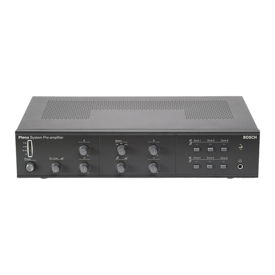
2.3 Voice alarm controller
2.3.1
Introduction
The LBB1990/00 Voice Alarm Controller is the heart of the Plena Voice Alarm System. The voice alarm controller distributes emergency calls, business calls as well as background music (BGM) to up to 6 loudspeaker zones.
2.3.4
Internal message manager
The voice alarm controller has an internal message manager, which maps wave files (.wav) to messages that can be played by the Plena Voice Alarm System.
2.3.5
Supervision
All necessary supervision features for compliance to evacuation standards are integrated into the voice alarm controller. If supervision is enabled and a fault is detected, the voice alarm controller lights a LED on its front panel that indicates the cause of the fault.
figure 2.2: Voice Alarm Controller
Note
When the voice alarm controller has been purchased in the Asian-Pacific Region, the emergency button has a different cover.
2.3.2
Hand-held microphone
The voice alarm controller is equipped with a hand-held microphone, which can be used to make emergency calls.
2.3.3
Internal power amplifier
The voice alarm controller has a 240 W internal power amplifier, which can be used in 1-channel or 2-channel mode. In the 1-channel mode, all calls and BGM are amplified by the internal power amplifier. If desired, an external power amplifier can be connected for spare switching. In the 2-channel mode, the BGM is amplified by the internal power amplifier, whereas the calls are amplified by an external power amplifier.
2.3.6
Overview
See figure 2.3 for an overview of the controls, connections and indicators on the voice alarm controller:
1 Power LED/VU Meter — A combined power indicator and VU meter. The green power LED is lit if the voice alarm controller is connected to the mains or back-up power and switched on. The VU meter indicates the master VU level: 0 dB (red), — 6 dB, -20 dB (yellow).
2 Fault indicators — Twelve yellow system fault
LEDs (Processor reset, Network, Call/EMG, Music/
Spare , Ground short, Input, Mains, Battery, Message,
EMG mic
, RCP and Router) and twelve yellow loudspeaker line fault LEDs. Fault indication is only
possible if supervision is enabled (see section 5.7). If
supervision is disabled, the yellow Disabled LED is lit.
3 Fault state buttons — Two buttons to acknowledge
(Ack) and reset (Reset) the fault state (see section
5.7).
4 Emergency state buttons — Two buttons to acknowledge (Ack) and reset (Reset) the emergency
state (see section 5.6).
5 Emergency call zone selectors — Six buttons to select the zones to which the emergency call must be
distributed (see section 5.6). Each button has a green
and a red LED. The six red LEDs indicate the zones that are selected for the emergency call. The six green LEDs indicate the zones in which a business call is running.
Bosch Security Systems | 2005-04 | 9922 141 10364en
Plena Voice Alarm System | Basic System Manual | System Overview en | 13
1 2 3 4 5
Plena Voice Alarm Controller
0 dB
-6dB
-20dB
Fault Indicators
Processor reset
Network
Call/EMG
Music/Spare
Ground short
Input
Mains
Battery
Message
EMG mic
RCP
Router
A
Disabled
B
Zone1
Zone2
Zone3
Zone4
Zone5
Zone6
Alert message
EMG mic
Alarm message
All call
Indicator test
Fault
Ack
Reset
EMG
Select
CD/Tuner Aux
Zone select
Zone1
Zone select
+
Zone2
+
0
Zone3
17 16 15 14
13
12 11
10
9 8 7 6
Zone4 Zone5
18 19 20 21
Zone6
Alarm
22 23 24 25 26 27 28 29 30 31
Int Booster
Ext Booster
A
Z1
Z2
Z3
Z4
Z5
Z6
Ext
B ooster
In
100V
0
100V
0
100V
0
100V
0
100V
0
100V
0
100V
0
DC In 24V
1 Channel
BGM/ C all
N.C ./Spare
2 Channel
BGM/ Spare
C all
Override/Trigger Output
B
100V
0
100V
0
100V
0
100V
0
100V
0
100V
0
100V
70 V
0
10 0V
Z1
Z1
24V
Z2
Z3
Z4
Z5
Z6
Z2
Z3
Z4
Z5
Z6
TRG 1
Int
B ooster
Out
C all out
GND
NC
COM
NO
EM G
NC
COM
NO
Fault
NC NO
COM
NC
COM
NO
C all
NC
24V
NO
Volume Override
TRG2
Out
External Booster
Trigger input/24V DC out
Emergency
1 2 3 4 5 6
24V
DC out
Business
1 2 3 4 5 6
VO X
Switch
10 k 10 k
1 2 3 4 5 6
24V
DC out
1 2 3 4 5 6
VO X Switch
In
CD/Tuner AU X PC
L
R
Call station
1
For ser vice only
SEL1
SEL0
Firmware
Upgrade
Off
2
On
Monitor
APR mode
Supervision
2ch operation
Reserved
Impedance
Calibration
GND
Mic/Line
Vox
115V~
230V~
LBB 1 990 /00 8900 199 0 0001
Plena Voice Alarm Controller
Max. output power 360W
Rated output power 240W
115-230V~, 50/60Hz
S/N.
Design & Quality
The Netherlands
N6 63
Apparatus delivered
C onnected for 230V~
Power
RS232
USB
Off
On
Vox
Speech filter
Phantom power
Off
On
EMG. Mic
Digital
Mess age
Monitoring
Speaker
Reserved
Line fuse
T6.3L250V for230V AC
T10L250V for115V AC
Remote Control Panel
1
2
Router
Rated input power :760VA
W arning
This apparatus must be earthed
47 46 45 44 43 42 41 40 39
figure 2.3: Front and rear views of the voice alarm controller
6 BGM zone selectors — Six buttons to select the
zones to which the BGM is distributed (see section
5.4). Each button has a green LED and a rotary
knob. The six green LEDs indicate the zones to which BGM is distributed. The six rotary knobs are local volume controls that can be used to adjust the volume of the BGM in each zone.
38 37 36 35 34 33 32
7 BGM master volume control — A rotary knob to
set the master volume of the BGM (see section 5.4).
8 BGM source selector — A button to select the
BGM source (CD/Tuner or Aux). The selected source
is indicated with a green LED (see section 5.4).
9 BGM tone controls — Two rotary knobs to control the high and low frequencies of the BGM (see
section 5.4).
Bosch Security Systems | 2005-04 | 9922 141 10364en
Plena Voice Alarm System | Basic System Manual | System Overview en | 14
10 All call button — A button to select all zones. This button is only available in the emergency state (see
section 5.6).
11 Indicator test button — A button to test all LEDs on the front panel of the voice alarm controller. All
LEDs are lit as long as the button is pushed (see
section 5.7).
12 Emergency button — A push button to put the
system in the emergency state (see section 5.6).
13 Alert message button — A button to select the alert message. This button is only available in the
emergency state (see section 5.6).
14 Alarm message button — A button to select the default alarm message. This button is only available
in the emergency state (see section 5.6).
15 Microphone socket — A socket to connect the
hand-held emergency microphone (see section 3.6).
16 Bracket — A bracket for the hand-held emergency microphone that is supplied with the voice alarm controller.
17 Monitoring speaker — Built-in monitoring speaker.
18 Zone outputs — Six zone outputs to connect loudspeakers to the voice alarm controller. Each zone output consists of two loudspeaker line outputs
(see section 3.10).
19 Override outputs — Six volume override outputs to override local volume controls in each zone (see
section 3.11).
20 Status outputs — Three status outputs to send the status of the Plena Voice Alarm System to third party
equipment (see section 3.14).
21 Trigger inputs/24 V DC output — Twelve trigger inputs to receive signals from third party equipment and one 24 V(DC) output. Except for the VOX switch input and the 24V DC out output, these must be configured with the configuration software and
are therefore not used in basic systems (see section
3.13).
22 Call station sockets — Two redundant RJ45 sockets to connect call stations (LBB1956/00) to the
voice alarm controller (see section 3.8).
23 Service settings — A set of DIP switches to service the voice alarm controller. Do not change the positions of the switches.
24 Calibration switch — A switch to calibrate the impedances of the loudspeaker lines for loudspeaker
supervision (see section 4.5.5.3).
25 Configuration settings — A set of DIP switches to
configure the voice alarm controller (see section 4.2).
26 PC socket — A USB socket to connect the voice alarm controller to a PC. Not for use in basic systems.
27 Emergency microphone volume control — A rotary knob to set the volume of the hand-held emergency microphone.
28 Reserved
29 Reserved
30 Voltage selector — A voltage selector to select the
local mains voltage (see section 3.15).
31 Power switch — A switch to switch the voice alarm
controller on and off (see section 5.1).
32 Ground — A connection to electrically ground the voice alarm controller.
33 Mains power inlet — A socket to connect the voice
alarm controller to the mains power (see section
3.15).
34 Router socket — An RJ45 socket to connect voice alarm routers (LBB1992/00) to the voice alarm controller. Not for use in basic systems.
35 Remote control panel socket — Two redundant
RJ45 sockets to connect remote control panels
(LBB1996/00, LBB1997/00) to the voice alarm controller. Not for use in basic systems.
36 Monitoring speaker volume control — A rotary knob to set the volume of the monitoring loudspeaker.
37 Digital message volume control — A rotary knob to set the volume of the digital business messages. This volume control does not influence the volume of the emergency messages.
38 Mic/line input with VOX functionality — An
XLR socket and a 6.3 mm jack with voice-activated
(VOX) functionality to connect a microphone or line
input to the voice alarm controller (see section 3.13).
The VOX settings are configured with the DIP
switches and the source switch (see section 4.6).
39 PC Call station input — An input to connect a PC call station. Not for use in basic systems.
Bosch Security Systems | 2005-04 | 9922 141 10364en
Plena Voice Alarm System | Basic System Manual | System Overview en | 15
40 BGM inputs — Two inputs to connect background music sources. Each input consists of two cinch
sockets (see section 3.7).
41 Line output — A line output to connect an external recording device to record the audio of the Plena
Voice Alarm System (see section 3.12).
42 External power amplifier (output) — An XLR socket to connect an external power amplifier (see
section 3.9). This socket is used in combination with
the external power amplifier input (no. 47).
43 Trigger outputs — Two general purpose trigger outputs. Not for use in basic systems.
44 Internal power amplifier output — Three pins that provide the 100 V audio signal of the internal power amplifier of the voice alarm controller.
45 Call output — An output that provides the call audio of the Plena Voice Alarm System.
46 Back-up power inlet — An inlet to connect a backup power supply to the voice alarm controller (see
section 3.15).
47 External power amplifier (input) — An input to
connect an external power amplifier (see section 3.9).
These pins are used in combination with the external
power amplifier output (no. 42).
2.4.1
Introduction
The LBB1956/00 Call Station can be connected to the
LBB1990/00 Voice Alarm Controller to make business calls. The call station is connected to the voice alarm controller using standard Cat-5 Ethernet cable.
figure 2.4: Call Station
The call station is not supervised. For compliance to evacuation standards, the Plena Voice Alarm System disables the call station during emergency calls.
Bosch Security Systems | 2005-04 | 9922 141 10364en
Plena Voice Alarm System | Basic System Manual | System Overview en | 16
2.4.2
Overview
See figure 2.5 for an overview of the controls, indicators
and connectors on the call station:
1 Power indicator — A green LED to indicate that the call station is powered on.
2 Zone selection buttons — Six buttons to select the zones to which the business call is distributed (see
section 5.5). Each button has a green LED, which
indicates the zones to which the business call is distributed.
3 ‘All call’ selector — A button to select all zones
(see section 5.5).
4 Push-to-talk button — A push-to-talk (PTT) button to start the business call.
5 Status indicators — Three LEDs that indicate the
status of the call station (see section 5.5).
6 Keypad connector — A connector to connect call station keypads (LBB1957/00) to the call station.
7 Configuration settings — A set of DIP switches to
configure the call station (see section 4.7).
8 Power supply inlet — A socket to connect a
24 V(DC) power supply (see section 3.8).
9 System sockets — Two redundant RJ45 sockets to connect the call station to the voice alarm controller
(LBB1990/00, see section 3.8).
Plena
1
2
3
5
4
figure 2.5: Top and bottom views of the call station
6 7
8
9
Bosch Security Systems | 2005-04 | 9922 141 10364en
Plena Voice Alarm System | Basic System Manual | Installation en | 17
3 Installation
3.1 Introduction
This chapter describes how to install a basic Plena
Voice Alarm System.
3.2 Requirements
Before starting to install the basic system, check if the installation site(s) for the voice alarm controller and call station meet the environmental, electrical and physical
requirements that are listed in chapter 6.
3.3 Unpacking
The voice alarm controller and the call station are shipped in boxes. For the contents of these boxes, see
table 3.1 and table 3.2.
3.4 CD-ROM
The CD-ROM in the box of the voice alarm controller contains:
• Plena Voice Alarm System configuration software
• Audio tools (e.g. converters)
• Default messages and chimes
• Plena info
• Basic System Manual
• Installation and User Instructions
• Bosch data book
The voice alarm controller is suitable for table-top and
19-inch rack-mounting installation. Two brackets for rack-mounting are supplied. See figure 3.1 for installation details.
Note
Always compare the contents of a shipment with the descriptions on the shipment documents.
Plena
0 dB
-6dB
-20dB
Voice
Alarm
Fault In dicator s
Proces
Netwo sor res rk
Call/E
M G et
Music/S
Groun pare d short
Contro ller
Mains
Battery
Messa ge
EMG
RCP
Route mic
A
Alert m essage
EMG mic
Alarm messa ge
Disable
B d
Zone1
Zone2
Zone3
Zone4
Zone5
Zone6
All call
Fault
Ack EMG
Reset
+
Select
CD/Tu ner
Aux
Zone select
Zone1
Zone select
Zone2
+
0
Zone3
Zone4
Zone5
Zone6
Alarm
table 3.1: LBB1990/00 contents
Description
Voice alarm controller
Safety instructions
Basic system manual
CD-ROM (see section 3.4)
Power cord
Emergency microphone
19” rack-mounting brackets
USB cable
Quantity
1 x
1 x
1 x
1 x
1 x
1 x
2 x
1 x
figure 3.1: Brackets for rack-mounting
Make sure that there is a free space of at least 100 mm on both sides of the unit for ventilation. The voice alarm controller has an internal fan, which is regulated to keep the temperature inside the unit within the safe operating area.
table 3.2: LBB1956/00 contents
Description
Call station
Cat-5 cable
Quantity
1 x
1 x
Caution
Keep the equipment boxed until the moment of installation. Boxed equipment is relatively well protected.
Bosch Security Systems | 2005-04 | 9922 141 10364en
Plena Voice Alarm System | Basic System Manual | Installation en | 18
The voice alarm controller has one connector for an emergency microphone. A hand-held emergency microphone is supplied with the voice alarm controller.
See figure 3.2 for installation details. Turn the lock ring clockwise to lock the plug.
The voice alarm controller has 2 BGM inputs (see figure
3.3 and table 3.3). Each BGM input has a double cinch socket. To these cinch outputs, a background music source can be connected (e.g. a PLN-DVDT Plena
DVD Tuner). The signals connected to the L (left) and R
(right) cinch sockets are mixed to form a single input signal.
Plena
0 dB
-6dB
-20dB
Voice
Alarm
Contro ller
Fault In dicator
Proces
Netwo
Call/E sor res
M G et
Music/ Spare
Groun d short
Input
Mains
Battery
Messag
EMG
RCP
Router mic
Alert m essag
EMG mic
Alarm messa ge
Disable
Zone1
Zone2
Zone3
Zone4
Zone5
Zone6
All call
Indicato r test
Fault
+
Ack
Reset
EMG
Select
Aux
Zone select
Zone1
Zone select
Zone2
+
Zone3
Zone4
Zone5
Zone6
Alarm
LBB1990/00
LBB1990/00
In
figure 3.2: Connecting the emergency microphone
CD/Tuner
AUX
figure 3.3: BGM inputs table 3.3: BGM inputs
Input Source
CD/Tuner
AUX
CD or tuner
Auxiliary source
Bosch Security Systems | 2005-04 | 9922 141 10364en
Plena Voice Alarm System | Basic System Manual | Installation en | 19
The call station can be connected to one of the shielded
RJ45 call station sockets on the voice alarm controller with a Cat-5 Ethernet cable. See figure 3.4 for connection details.
The voice alarm controller has 1 external power amplifier output (line level, 1 V) and 1 external power amplifier input (100 V) to connect an external power amplifier (see figure 3.6). The function of the external power amplifier (e.g. a PLN-1P120 Plena Power
Amplifier) depends on the channel mode for which the
voice alarm controller is configured (see section 4.5.11).
6
VOX tch
10k
10k
5
6 24V
DC ou t
5
6
VOX Sw itch
Call st ation
1
2
For ser vice on ly
SEL1
SEL0
Firmw
Upgrad e
Off
2
S
On
Impeda
Calibr nc
Z5 100V
Z6 100V
Ext
Booste 100V
DC In
24V
Int Bo
Ext B oster ooste
Z1 100V
A
1 Chan nel
BGM /Call
N.C./S pare
Z2
100V
Z3 100V
Z4 100V
2 Chan
BGM
Call nel
/Spare
B Overrid e/Trigg
100V
100V
Z1 Z1
100V
Z2
Z2
Z3
24V
100V
Z3 Z4
Z4 Z5
100V
100V
Z5
Z6
TRG
Z6
100V
70V Int
Booste
Out
100V
Call ou
GND
NC
COM
NO
EMG
NC
Fault
NC
CO
NO
COM
NO
NC
24V
Call
NO Volum e Over ride
TRG2
Out
Trigge r inpu
Emerg ency t/24V
DC ou
Busin ess
Externa l Boos ter
In
CD/Tu ner
AUX
VOX S witch
PC
Call sta tion
For ser vice on
SEL1
SEL0
Firmw
Upgrad
Off
On
Monito
APR
Superv mode
2ch op ision
LBB ance
Calibra tion
GND
Mic/L ine
Vox
Off
On
Vox
Spee
Off ch filte m pow
On
LBB 1
Plena
Max. o
Rated
S/N.
990/0
Voice Alarm utput p
0V~, 5 power 60W
Design
0/60H
The N ower 3 etherla & Qua lity nds ler
N663
USB
01
115V~
230V~
Appara
Conne tus deli cted fo vered r 230V
Line fu
T6.3L2
T10L2 se
50V fo
50V fo
Remote
Contro
Firema n’s pan
LBB19 r230V
AC
AC l Panel
94
Power
Rated input p ower:7
60VA
Digital
Messa ge
Monito
Speake ring
Router
This ap paratu s must be eart hed
LBB1990/00
LBB1990/00
LBB1956/00
Plena na
Ple
Z2
100V
0
100V
Z3
Z4
0
100V
0
100V
Z5
Z6
Ext
Booster
In
0
100V
0
100V
0
DC In 24V
0
Z2
100V
0
100V
Z2
Z3
Z3
Z4
0
100V
Z5
Z4
0
100V
Z6
Z5 TRG 1
0
100V
0
100V
Z6
70V
0
Int
Booster
Out
100V Call out
GND
NO
NC
COM
NO
Fault
COM
NC
COM
NO
Call
NC
24V
NO
Volume Override
TRG2
Out
External Booster
figure 3.4: Connecting a call station
If the cable between the call station and the voice alarm controller is longer than 100 m, the call station must be connected to a 24 V(DC) power source. See figure 3.5 for connection details.
LBB1956/00 na
Ple
+
1
—
3
G ND
2
G ND
1
—
3
+
2 line in line out
100V 70V 0
Plena
figure 3.5: Connecting a power supply
Bosch Security Systems | 2005-04 | 9922 141 10364en
PLN-1P120
figure 3.6: Connecting an external power amplifier
Plena Voice Alarm System | Basic System Manual | Installation en | 20
3.10 Loudspeakers
The voice alarm controller has 6 zone outputs (Z1 to
Z6 ). Each zone output consists of 2 redundant loudspeaker lines (line A and line B). Normally, calls and BGM are distributed to a zone over both loudspeaker lines. If one of the loudspeaker lines of a zone fails, it is still possible to distribute calls and BGM to the zone over the remaining loudspeaker line (see figure 3.7).
If it is necessary to detect the removal or failure of a single loudspeaker, the following is advised:
• Do not connect more than 5 loudspeakers to the same loudspeaker line (line A or line B). Field tests have shown that the impedance of loudspeakers and loudspeaker lines varies with temperature and age.
The limit of 5 loudspeakers is set due to this variation. In a more stable environment, the number of loudspeakers can be higher.
• Make sure that all loudspeakers connected to the same loudspeaker line have the same impedance.
LBB1990/00
Note
The impedance measurement of the Plena Voice
Alarm System has an accuracy better than 2%.
The system only generates a fault if the line impedance difference is greater than 15%
(default accuracy).
A
Ext
Booster
In
Z1
Z2
Z3
Z4
Z5
Z6
100V
0
100V
0
100V
0
100V
0
100V
0
100V
0
100V
0
DC In 24V
BGM/
B
0
100V
0
100V
0
100V
0
100V
70V
0
100V
0
100V
0
100V
Z1
Z2
Z3
Z4
Z5
Z6
Int
Booster
Out
100V Call out
Z6
Z5
Z4
Z3
6A
5A
4A
6B
5B
4B
Note
The maximum load for the internal power amplifier of the voice alarm controller is 240 W.
However, if the voice alarm controller is used in
2-channel mode and an external 480 W amplifier is connected to it, the maximum loudspeaker load can be 480 W at 100 V. This is because in 2-channel mode, the internal power amplifier of the voice alarm controller is used for BGM only and distributes BGM at
-3 dB, from which follows that the maximum power output is 240 W at 70 V and that the loading caused by 100 V loudspeakers at 70 V is also 240 W. The external amplifier is used for calls only with 480 W output power and 100 V loudspeaker line voltage.
3A 3B
Z2
2A 2B
Z1
1A 1B
figure 3.7: Connecting loudspeaker zones
Bosch Security Systems | 2005-04 | 9922 141 10364en
Plena Voice Alarm System | Basic System Manual | Installation en | 21
The voice alarm controller has 6 override outputs; 1 for
each zone in the system (see figure 3.8). These are
suitable for 4-wire override (24 V) as well as for 3-wire override.
Internally, the positive override pins (Z+) are all connected to either the NC or the NO contact of the
Volume Override
output (see figure 3.9). The negative
override pins (Z-) are all connected to earth.
Z1
+
_
Note
By default, the voice alarm controller is configured for 4-wire (24 V), power-saving override, see situation I in figure 3.10.
Z2
+
_
LBB1990/00
Z3
+
_
Z4
+
_
Override/Trigger Output
Z3
Z4
Z5
Z1
24V
Z2
Z6
TRG 1
NC
COM EMG
NO
NC
COM
NO
Fault
NC NO
COM
NC
COM
NO
Call
NC
24V
NO
Volume Override
TRG2
figure 3.8: Override outputs
Z5
+
_
Z6
+
_
figure 3.9: Volume override contacts
NO NC
Normally, when there are no active calls, the Z+ pins are internally connected to the NC contact of the
Volume Override . At the moment a call is started in a zone, the Z+ pin of the zone is internally connected to the NO contact of the Volume Override. So, the NC and the NO contacts determine which voltage is supplied to the positive pins of the override outputs (Z+).
Bosch Security Systems | 2005-04 | 9922 141 10364en
Plena Voice Alarm System | Basic System Manual | Installation en | 22
See figure 3.10, situation I for an example of a fail-safe
4-wire volume override:
• Connect the NO contact of the Volume Override to the 24V contact of the Volume Override.
See figure 3.10, situation II for an example of a power-saving 4-wire volume override:
• Connect the NC contact of the Volume Override to the 24V contact of the Volume Override.
LBB1990/00
NC
NO
Override/Trigger Output
Z1
24V
Z2
Z3
Z4
Z5
Z6
G 1
NC
COM
NO
EM
NC
COM
NO
Fault
NC NO
COM
NC
COM
NO
Call
NC
24V
NO
Volume Override
TRG2
100V
0V
24V
0V
Override/Trigger Output
Z1
24V
Z2
Z3
Z4
Z5
Z6
G 1
NC
COM
NO
EM
NC
COM
NO
Fault
NC NO
COM
NC
COM
NO
Call
NC
24V
NO
Volume Override
TRG2
100V
0V
24V
0V
figure 3.10: 4-wire volume override
NO
NC
Bosch Security Systems | 2005-04 | 9922 141 10364en
Plena Voice Alarm System | Basic System Manual | Installation en | 23
To create a 3-wire volume override, see figure 3.11:
Note
It is not possible to use 3-wire volume override in a basic system, because it must be enabled using the configuration software. See the
Installation and User Instructions
(9922 141 1037x) and the Configuration
Software Manual (9922 141 1038x) for more information.
Note
It is not possible to use 3-wire volume override in combination with redundant loudspeaker lines
(line A and B, see figure 3.7). If redundant loudspeaker lines are needed, use 4-wire volume override (see figure 3.10).
• Connect the 100V output of loudspeaker line A to the 100 V input of the volume control.
• Connect the 100 V/0 V (CALL/RTN) of the transformer to the 100V output of loudspeaker line
B
.
• Connect the 0 output of loudspeaker line A to the
0 V of the loudspeaker.
• Enable 3-wire volume override in the configuration software.
The voice alarm controller has one line output (see figure 3.12). This output has a double cinch socket. Both cinch sockets contain the same, mono signal, which consists of the current BGM and calls. The line output can be used to connect the voice alarm controller to a recording device (e.g. a tape-deck).
LBB1990/00
Booster
figure 3.12: Line output
In
CD/Tuner
Caution
Make sure that the correct connections have been made and the system is correctly configured.
100V
A
100V
B
0V
A
figure 3.11: 3-wire volume override
Bosch Security Systems | 2005-04 | 9922 141 10364en
Plena Voice Alarm System | Basic System Manual | Installation en | 24
3.13 Mic/line input with VOX functionality
The voice alarm controller has 1 mic/line input with
voice-activated (VOX) functionality (see figure 3.13).
This input has two sockets; one balanced XLR socket and a balanced 6.3 mm jack socket. The signals from both sockets are mixed to form a single input signal.
In basic systems, the default priority of the mic/line input with VOX functionality is 6. This means that it can be used to make business calls (e.g. with a
PLN-MM Plena Message Manager). The input automatically starts a business call if the input is higher than -20 dB (100 mV for line and 100
µ
V for microphone inputs) or if the VOX switch is closed (see
figure 3.14).
LBB1990/00
p
Calibration
GND
Note
In extended systems, the mic/line input with
VOX functionality can also be used to make emergency calls. For example, it can be used to create a supervised link to another emergency sound system (e.g. a Praesideo system). See the Installation and User Instructions
(9922 141 1037x) for more information.
L
Mic/Lin
PC
R
LBB1990/00
figure 3.13: Mic/line input with VOX functionality
1 2 3 4 5 6
24V
DC out
1 2 3 4 5 6
VOX Switch
figure 3.14: Connecting a VOX switch
Bosch Security Systems | 2005-04 | 9922 141 10364en
Plena Voice Alarm System | Basic System Manual | Installation en | 25
3.14 Status output contacts
The voice alarm controller has 3 status output contacts
to indicate the current system state (see figure 3.15).
These are used to send the status of the Plena Voice
Alarm System to third party equipment or to connect sounders or similar indicating devices.
LBB1990/00
3.15 Power
3.15.1
Introduction
The voice alarm controller has the following power connections:
•
Mains power connection (see section 3.15.2).
•
Back-up power connection (see section 3.15.3).
3.15.2 Mains power
Proceed as follows to connect the voice alarm controller to the mains power:
1 Select the local mains voltage using the voltage selector on the rear of the voice alarm controller.
Z5
Z6
TR
Z1
Z2
Z3
Z4
NC
COM
NO
EMG
NC
COM
NO
Fault
NC
COM
NO
Call
NC
24V
NO
V olume Overr
TRG2
LBB1990/00
115V~ 230V~
NC
COM
NO
Apparatus delivered
Connected for 230V~
figure 3.15: Status output contacts (default) table 3.4: Status output contact
Contact Description
EMG
Fault
Call
Emergency state. See section 5.6
Fault state. See section 5.7
Call active state.
The status output contacts are internal relays. By default, NC is connected to COM. When the Plena
Voice Alarm System enters one of the states that are
indicated in table 3.4, the relay connects NO to COM.
Power
figure 3.16: Voltage selector table 3.5: Voltage selector
Selector Mains voltage
V(AC)
115
230
100 — 120
220 — 240
Fuse
115 V — 10 AT
230 V — 6.3 AT
Note
The LBB1990/00 Voice Alarm Controller is delivered with the voltage selector in the 230 position.
Bosch Security Systems | 2005-04 | 9922 141 10364en
Plena Voice Alarm System | Basic System Manual | Installation en | 26
2 Put the correct type of fuse in the voice alarm
controller (see table 3.5).
Note
The LBB1990/00 Voice Alarm Controller is delivered with a T6.3L 250 V fuse for a mains voltage of 220 to 240 V(AC).
3 Connect a locally approved mains cord to the voice
alarm controller (see figure 3.17).
4 Connect the mains cord to a locally approved mains
outlet (see figure 3.17).
3.15.3 Back-up power
The voice alarm controller has a 24 V(DC) input to connect a back-up power supply (e.g. a battery) which powers the system if the mains power is not available.
See figure 3.18 for connection details.
Z6
00V
Booste
In r
0
100V
0
DC In
24V
Z2
Z3
Int Bo
Ext B
Z1 100V
100V
100V oster ooste
A
Z4 100V
Z5
100V
Boos ter 100V
DC In
Z6 100V
24V
BGM /Call
BGM
2 Chan
Call nel
B
100V
100V
Z1
Overrid e/Trigg er Outp ut
24V
Z1
100V
Z2
Z2
Z3
NC
COM
NO
EMG
NC
Fault
NC
COM
NO
100V
100V
Z3
Z4
Z4
Z5
100V
Z5
TRG
Z6
Z6
100V
70V Int
Booste
Out
100V
Call ou
COM
NO
NC
24V
NO
TRG2
Call
Volum
Out e Over ride
GND
Externa l Boos ter
Trigge r input
Emerg
/24V ency DC ou
Busin ess
In
DC ou 24V
Switch VOX
DC ou
24V
CD/Tu ner
AUX
VOX S witch
PC
Call sta tion
For serv ice only
SEL1
SEL0
Firmw
Upgrad are
Off
On
Monitor
APR
Superv
2ch ope
LBB19 ision ration
94
Imped ance tion
GND
Mic/Lin
Vox
Vox
Speec
Phanto h filter m pow
Off
On
Off
On
Plena
Max. o
Rated output
S/N.
Voice utput p
115-2 30V~
Alarm 8900
Contro
60W ller
199 000
01
, 50/6 power
0Hz 240W
Design
The N etherla nds
N663
USB
Line fu
T6.3L2
T10L2
Remote se
50V fo
50V fo
LBB199 r230V r115V
AC
AC
Contro l Panel
115V~
230V~
Appara
Conne tus deli vered r 230
V~
Power
Rated input p ower:7
60VA
Digital
Messa ge
Monito
Router
This ap paratu s must be eart hed
LBB1990/00
00 na Voic e Alarm power
230V
.
8900
Contro ller
/60H z
W
199 000
01
The N etherla nds
N663
USB
115V~
230V~
Firema n’s pan el
Power
Rated input powe r:760VA
T10L25
0V for1
LBB19
94
Line fuse
50V fo r230V
Remot e Cont
15V A
AC
C rol Pan el
Appa
Conn ratus d ected elivere d
V~
Mess age
Monit oring
1
Router
2
DC In
Int Bo
Ext B oster ooste
Z1
Z2
Z3
Z4
Z5
Z6
100V
100V
100V
100V
100V
100V
100V
24V
A
1 Chan
BGM nel
N.C./S /Call pare
2 Chan nel
BGM
Call
/Spare
B
100V
Overrid e/Trigg er Outp ut
Z1 Z1
24V
100V
100V
Z2
Z2
Z3
Z3
Z4
100V
100V
100V
Z4 Z5
100V
70V
Z5
Z6
TRG
100V
Z6
Int
Booste
Out
Call ou
GND
NC
EMG
Out
NC
COM
NO
NC
Fault
COM
Call
COM
NO
NC
24V
NO
TRG2
Volum e Over ride
NO
Extern al Boo ster
Trigge
Emerg r inpu ency t/24V
DC ou
Busin ess
In
24V
DC ou
VOX
Switch
24V
DC ou
CD/Tu ner
AUX
VOX S witch
PC
Call sta tion
For ser vice on
Off
SEL1
SEL0 are
Upgrad
Monito
APR
Super mode
2ch op
LBB19 vision
94
On
Imped ance tion
GND
Mic/Line
Vox
Vox
Speec
Phanto
Off
Off
On
LBB 19 90/00
Plena
Max. o
115-23
S/N.
Voice Alarm d outp ut pow
Contro
60W
8900
W
199 00 ller 001
Design
0/60H
The N etherla & Qua lity nds
N663
USB h filter m pow
115V~
230V~
Line fu
T6.3L2
se
50V fo
LBB199
T10L2 50V fo
Remote r115V
Contro r230
V AC
AC l Panel
Appara tus de
Conne cted fo livered r 230V
Firema n’s pan
Power
Rated input p ower:7
60VA
On
Digital
Messa ge
Monito
Speake ring
Router
Warni
This ap ng paratu s mu st be earthe
LBB1990/00
Charger
—
24
VDC
+
figure 3.18: Connecting a back-up power supply figure 3.17: Connecting the mains cord
Bosch Security Systems | 2005-04 | 9922 141 10364en
Plena Voice Alarm System | Basic System Manual | Configuration en | 27
4 Configuration
4.1 Introduction
A basic system is configured using the DIP switches and volume controls on the rear of the voice alarm controller and the DIP switches on the bottom of the call station.
4.3 Monitor
If the Monitor switch (see figure 4.1) is in the ON
position, the internal monitoring loudspeaker of the voice alarm controller is switched on. The volume of the monitoring loudspeaker is set with the Monitoring
Speaker
volume control (see figure 2.3, no. 36).
4.2.1
Introduction
The system settings are configured using DIP switches
on the rear of the voice alarm controller (see figure 4.1).
By default, all switches are in the OFF position.
Monitor
APR mode
Supervision
2ch operation
Reserved
Off
On
figure 4.1: System settings DIP switches
If the APR mode switch (see figure 4.1) is in the ON
position, the system is in the Asian-Pacific Region (APR) mode. In APR mode, the system operates according to the emergency standards of the Asian-Pacific Region.
For a basic system, the differences between normal operation and the APR mode are:
•
When the emergency button (see figure 2.3, no. 12)
is pushed on the front of the voice alarm controller, an alarm message is automatically started. This message is automatically repeated.
• In the APR mode the red LED, which during normal operation indicates that the zone is selected for an
emergency call (see figure 2.3, no. 5), does not work.
• In the APR mode the green LED, which during normal operation indicates that a business call is
running in the zone (see figure 2.3, no. 5), indicates
that an emergency call is running in the zone.
table 4.1: System settings DIP switches
DIP switch Description
Monitor
APR mode
Reserved
Switches the monitoring loudspeaker on (ON) and off (OFF).
See section 4.3.
Switches the Asian Pacific Region mode on (ON) and off (OFF). See
Supervision
section 4.4.
Switches supervision on (ON) and
off (OFF). See section 4.5.
2ch operation Switches 2-channel operation on
(ON) and off (OFF). See section
4.5.11.
Reserved. This DIP switch must always be in the OFF position.
Bosch Security Systems | 2005-04 | 9922 141 10364en
Plena Voice Alarm System | Basic System Manual | Configuration en | 28
4.5 Supervision
4.5.1
Introduction
If the Supervision switch (see figure 4.1) is in the ON
position, supervision is enabled. If it is in the OFF position, supervision is disabled.
Note
Supervision is only necessary for systems that have to comply to the IEC60849 evacuation standard. If the system does not have to comply to this standard, leave the switch in the OFF position.
If the Supervision switch is in the OFF position, the
Disabled
indicator on the front panel of the voice alarm
controller is lit (see figure 4.2) to indicate that
supervision is switched off.
0 dB
-6dB
-20dB
Fault Indicators
Processor reset
Network
Call/EMG
Music/Spare
Ground short
Input
Mains
Battery
Message
EMG mic
RCP
Router
A
Disabled
B
Zone1
Zone2
Zone3
Zone4
Zone5
Zone6
4.5.2
Overview
The supervised functions can be configured with a PC and the configuration software. To basic systems, the default settings apply (see table 4.2).
table 4.2: Default supervision settings
Supervision of:
Processor
Default setting
On. See section 4.5.3.
Network
Messages
Off.
On. See section 4.5.4.
Line supervision
On. See section 4.5.5.
Emergency microphone
On. See section 4.5.6.
Input contacts Off.
Mains power
Battery power
On. See section 4.5.7.
On. See section 4.5.8.
Internal power amplifier
On. See section 4.5.9.
VOX 20 kHz input Off.
External power amplifier Depends on position of the 2ch operation switch.
See section 4.5.11.
Note
See section 5.7 for information about faults.
figure 4.2: Disabled indicator
4.5.3
Processor supervision
If supervision is enabled (see section 4.5.1), the
processor of the voice alarm controller is supervised by a watchdog. If the watchdog triggers, the Processor reset indicator on the front panel of the voice alarm controller is lit. Then, the program memory is checked and the processor resumes operation within 10 seconds.
The indicator remains on until the fault is acknowledged and reset.
Bosch Security Systems | 2005-04 | 9922 141 10364en
Plena Voice Alarm System | Basic System Manual | Configuration en | 29
4.5.4
Message supervision
If supervision is enabled (see section 4.5.1), the internal
message manager of the voice alarm controller is supervised. This message supervision consists of supervision of the wave player using a check-sum and supervision of the audio path using a pilot tone.
4.5.6
Emergency microphone
If supervision is enabled (see section 4.5.1), the audio
path and the PTT switch of the emergency microphone are monitored from the capsule to the connection with the voice alarm controller.
4.5.5
Line supervision
4.5.5.1
Introduction
If supervision is enabled (see section 4.5.1), all
loudspeaker lines are supervised. Line supervision consists of:
•
Short-circuit supervision (see section 4.5.5.2).
•
Impedance supervision (see section 4.5.5.3).
•
Short-to-ground supervision (see section 4.5.5.4).
4.5.5.2
Short-circuit supervision
The voice alarm controller continuously monitors all loudspeaker lines in the system for short-circuits. If a short-circuit is detected, the line output of the short-circuited line is isolated and shut down within 200 ms. The system will remain operational. If the line is dual-redundant connected (A and B) the short-circuited line remains operational as well.
4.5.7
Mains power supervision
If supervision is enabled (see section 4.5.1), the
availability of the mains power is supervised.
4.5.8
Battery supervision
If supervision is enabled (see section 4.5.1), the
availability of the back-up power is supervised.
4.5.9
Internal power amplifier supervision
If supervision is enabled, the internal power amplifier of the voice alarm controller is supervised. The function of this power amplifier depends on the position of the 2ch operation
switch (see section 4.5.11).
table 4.3: Internal power amplifier functions
Operational mode Function
1-channel
2-channel
BGM/Call power amplifier
BGM/Spare power amplifier
4.5.5.3
Impedance supervision
If supervision is enabled, the voice alarm controller measures the impedance of all loudspeaker lines once every 90 seconds. The reference values for impedance supervision are stored in the voice alarm controller
during the system calibration (see section 5.3). If a
difference of > 15% is detected between the measured line impedance and its reference value, the line is considered faulty.
4.5.10 External power amplifier supervision
If supervision is enabled and the 2ch operation switch
(see section 4.5.11) is in the ON position, the external
power amplifier is supervised. In 2-channel mode, the external power amplifier is always the call power amplifier.
Note
For a correct impedance supervision, connect
loudspeakers as described in section 3.10.
4.5.5.4
Short-to-ground supervision
If supervision is enabled, the voice alarm controller continuously monitors all loudspeaker lines in the system for short-to-ground situations. If a leakage current > 30 + 15 mA is detected in a line, the line is considered faulty.
Bosch Security Systems | 2005-04 | 9922 141 10364en
Plena Voice Alarm System | Basic System Manual | Configuration en | 30
4.5.11 1 channel and 2 channel operation
4.5.11.1
Introduction
If the 2ch operation switch (see figure 4.1) is in the ON
position, the voice alarm controller operates in the
2-channel mode. If the 2ch operation switch is in the
OFF position, the voice alarm controller operates in the
1-channel mode.
4.6.1
Introduction
The type of source that is connected to the mic/line input with VOX functionality is set using the Mic/Line switch on the rear of the voice alarm controller (see
figure 4.3).
• If the source is a microphone, put the switch in the
Mic
position.
• If the source is a line-level source, put the switch in the Line position.
4.5.11.2
1-channel mode
In the 1-channel mode, all calls and BGM are amplified by the internal power amplifier of the voice alarm controller. If desired, an external power amplifier can
be connected for spare switching (see section 3.9). In 1-
channel mode, all calls will interrupt the BGM. The
external power amplifier is not supervised (see section
4.5.10).
Vox
Speech filter
Phantom power
Off
Mic/Line
On
figure 4.3: VOX input source switch table 4.4: 1-channel mode
Amplifier Function
Internal
External
BGM/Call power amplifier
Not connected/Spare power amplifier
The mic/line input with VOX functionality is configured using DIP switches on the rear of the voice
alarm controller (see figure 4.4). By default, all switches
are in the OFF position.
4.5.11.3
2-channel mode
In the 2-channel mode, the BGM is amplified by the internal power amplifier of the voice alarm controller.
The calls are amplified by the external power amplifier, which is connected to the voice alarm controller
(see section 3.9). If the external power amplifier is
faulty, the calls are amplified by the internal power amplifier. In 2-channel mode, calls do not interrupt the
BGM. Both the internal power amplifier and the
external power amplifier are supervised (see section
4.5.10).
Mic/Line
figure 4.4: VOX settings
Vox
Speech filter
Phantom power
Off
On
The settings that can be made using the DIP switches are explained in a table on the rear of the voice alarm
controller (see figure 4.5).
table 4.5: 2-channel mode
Amplifier Function
Internal
External
BGM/Spare power amplifier
Call power amplifier
Off
1 VOX activate by mic.
2 Speech filter
3 Phantom power Off
figure 4.5: VOX settings table
On
VOX activate by VOX Switch
Flat
Phantom power On
Bosch Security Systems | 2005-04 | 9922 141 10364en
Plena Voice Alarm System | Basic System Manual | Configuration en | 31
The volume of the mic/line input with VOX functionality is set with the VOX volume control (see
figure 4.6).
4.7.1
Introduction
The call stations are configured using the DIP switch at
the bottom (see figure 4.7).
Vox
Speech filter
Phantom power
Off
Mic/Line
On
figure 4.6: VOX volume control
4.6.2
Vox
If the Vox switch is in the OFF position, the input is activated when the voltage of the signal of the source is above the specified threshold. If the Vox switch is in the
ON
position, the input is activated when the VOX
Switch
trigger input is closed (see also section 3.13).
4.6.3
Speech filter
If the Speech filter switch is in the OFF position, a speech filter is activated for the mic/line input with
VOX functionality. The speech filter improves the speech intelligibility by cutting off the lower frequencies.
figure 4.7: Call station DIP switches table 4.6: Call station DIP switches
DIP switch Description
1, 2, 3, 4
5, 6
7
8
Set the ID of the call station. See
section 4.7.2
Set the sensitivity of the call station.
See section 4.7.3.
Switches the speech filter on (ON)
and off (OFF). See section 4.7.4.
Switches termination on (ON) and
off (OFF). See section 4.7.5.
4.6.4
Phantom power
If the Phantom power switch is in the ON position, a phantom power supply is activated. This switch only has to be put in the ON position if the source is a microphone that must receive phantom power. If the source is not a microphone or if the microphone does not accept phantom power, leave the switch in the OFF position.
4.7.2
Call station ID
The ID of the call station is set using switches 1 to 4.
Since a basic system can contain only 1 call station, the
ID of this call station is 1. This is accomplished by leaving the DIP switches 1 to 4 in the default OFF position.
Bosch Security Systems | 2005-04 | 9922 141 10364en
Plena Voice Alarm System | Basic System Manual | Configuration
4.7.3
Sensitivity
The sensitivity of the call station is set using switches 5
and 6 (see table 4.7).
table 4.7: Call station sensitivity
Sensitivity Switch 5
-15 dB
0 dB
6 dB
Reserved
OFF
OFF
ON
ON
Switch 6
OFF
ON
OFF
ON
4.7.4
Speech filter
If switch 7 is in the ON position, a speech filter is activated for the call station. The speech filter improves the speech intelligibility by cutting off the lower frequencies.
4.7.5
Termination
Switch 8 must always be in the ON position, since basic systems contain only 1 call station.
en | 32
Bosch Security Systems | 2005-04 | 9922 141 10364en
Plena Voice Alarm System | Basic System Manual | Operation en | 33
5 Operation
Note
It is assumed that the APR mode switch (see
section 4.4) is in the OFF position.
Put the Power switch on the rear of the voice alarm controller (see figure 5.1) in the I position.
115V~ 230V~
Put the Power switch of the voice alarm controller (see figure 5.1) in the O position.
5.3 Calibration
Calibration is necessary for a correct loudspeaker line
impedance supervision (see section 4.5.5.3). To calibrate
the voice alarm controller, push the calibration switch
(see figure 2.3, no. 24). The system must be calibrated:
• When the voice alarm controller is switched on for the first time.
• After the connected loudspeakers are changed.
• After loudspeakers have been added.
• After the settings of the connected loudspeakers have been changed.
Apparatus delivered
Connected for 230V~
figure 5.1: Power switch
Power
If mains power or back-up power is available, the power indicator on the front of the voice alarm controller is lit
(see figure 5.2). If the basic system contains a call
station, the power indicator of the call station is also lit
(see figure 2.5, no. 1).
5.4.1
Introduction
The background music (BGM) is controlled using the
BGM controls on the front of the voice alarm controller
(see figure 2.3). Proceed as follows to route BGM:
1 Select the BGM source (see section 5.4.2).
2 Select the zones (see section 5.4.3).
0 dB
-6dB
-20dB
Fault Indicators
Processor reset
Network
Call/EMG
Music/Spare
Ground short
Input
Mains
Battery
Message
EMG mic
RCP
Router
A
Disabled
B
Zone1
Zone2
Zone3
Zone4
Zone5
Zone6
5.4.2
Select BGM source
Select the BGM source with the Select button (see
figure 5.3). A green LED indicates the source that is
selected.
• If the source is a CD player or a tuner that is
connected to the CD/Tuner input (see section 3.7),
choose CD/Tuner.
• If the source is an auxiliary source that is connected
to the Aux input (see section 3.7), choose Aux.
figure 5.2: Power indicator
Select
CD/Tuner Aux
Zone select
Note
When the system is switched on for the first time and supervision is enabled, calibrate the
system (see section 5.3).
+
—
+
0
figure 5.3: BGM source selector
Bosch Security Systems | 2005-04 | 9922 141 10364en
Plena Voice Alarm System | Basic System Manual | Operation en | 34
5.4.3
Select zones
The BGM is distributed to the zones with the Zone select
buttons (see figure 5.4). A green LED indicates
the zones to which BGM is distributed.
• If the Zone select indicator is off, no BGM is distributed to the zone. Push the Zone select button to distribute the BGM to the zone.
• If the Zone select indicator is on, BGM is distributed to the zone. Push the Zone select button to stop distributing the BGM to the zone.
5.4.5
Adjust frequencies
The voice alarm controller has two rotary knobs to
adjust the sound of the BGM (see figure 5.6).
• Use the upper rotary knob to adjust the treble or high frequency content of the BGM.
• Use the lower rotary knob to adjust the bass or low frequency content of the BGM.
Select
CD/Tuner Aux
Zone select
Select
CD/Tuner Aux
Zone select
+
+
—
+ 0
figure 5.6: BGM tone controls
—
+ 0
figure 5.4: BGM zone selectors
5.4.4
Adjust volume
The voice alarm controller has two types of controls to
adjust the BGM volume (see figure 5.5). The overall
(maximum) volume of the BGM source is set with the master volume control, which is located below the BGM
source selector (Select button, see figure 5.3). Per zone,
the local volume can be adjusted with the zone volume switches, which are located below the zone selection
buttons (Zone select, see figure 5.4).
Select
CD/Tuner Aux
Zone select
+
+
0
figure 5.5: BGM volume controls
Bosch Security Systems | 2005-04 | 9922 141 10364en
Plena Voice Alarm System | Basic System Manual | Operation en | 35
5.5.1
Introduction
Business calls can only be distributed with call stations.
It is not possible to use the hand-held emergency microphone to distribute business calls. Proceed as follows to distribute a business call:
1 Select the zones (see section 5.5.2).
2 Make the announcement (see section 5.5.3).
5.5.3
Make the announcement
Push the push-to-talk (PTT) button of the call station to
make an announcement (see figure 5.8). The call is only distributed to the selected zones (see section 5.5.2).
Plena
5.5.2
Select zones
Select the zones to which the business call must be distributed with the zone selection buttons on the call station (see figure 5.7). A green LED indicates the zones to which the business call is distributed.
• If the indicator of a button is off, the zone is not selected. Push the button to select the zone.
• If the indicator of a button is on, the zone is selected.
Push the button to deselect the zone.
Plena
Z4
Z5
Z6
Z1-Z6
Z1
Z2
Z3
figure 5.8: PTT button and indicators
The LEDs above the PTT button provide information
about the status of the call station (see table 5.1).
table 5.1: Call station status indicators
Indicator
Green
Yellow
Red
Description
PTT button is pushed.
Fault in the system.
System is in emergency state. The call station is disabled.
figure 5.7: Zone select buttons
Bosch Security Systems | 2005-04 | 9922 141 10364en
Plena Voice Alarm System | Basic System Manual | Operation en | 36
5.6.1
Introduction
Emergency calls can only be distributed when the
system is in the emergency state. See section 5.6.2 for
information about entering the emergency state. In the emergency state, it is possible to distribute the following emergency calls:
• Live speech with the emergency microphone of the
voice alarm controller (see section 5.6.5).
5.6.3
Acknowledge the emergency state
The beeper can be switched off by acknowledging the
emergency state with the EMG Ack button (see figure
5.10).
Fault
Ack
Reset
EMG
Zone select
Zone1 Zone2
Note
It is not possible to distribute chimes or speech with the call station when the system is in the emergency state, because the call station is disabled automatically at the moment that the system enters the emergency state.
figure 5.10: EMG Ack button
5.6.4
Exit the emergency state
Exit (reset) the emergency state by pushing the EMG
Reset
button (see figure 5.11). In order to reset the emergency state, it first must be acknowledged (see
section 5.6.3).
•
The default alert message (see section 5.6.6).
•
The default alarm message (see section 5.6.7).
5.6.2
Enter the emergency state
To enter the emergency state, push the emergency button on the front of the voice alarm controller (see
figure 5.9). The red LED that is integrated in the switch
lights.
Fault EMG
Ack
Zone select
Reset
figure 5.11: EMG Reset button
Zone1 Zone2
5.6.5
Distribute live speech
Alert message All call
EMG mic
Alarm message
Indicator test
5.6.5.1
Introduction
Proceed as follows to distribute live speech:
1 Select zones (see section 5.6.5.2).
2 Make announcement (see section 5.6.5.3).
figure 5.9: Emergency button
At the moment the emergency state is entered, a beeper starts and the EMG status output contact is closed.
Note
See section 5.6.4 for information about exiting
the emergency state.
Bosch Security Systems | 2005-04 | 9922 141 10364en
Plena Voice Alarm System | Basic System Manual | Operation en | 37
5.6.5.2
Select zones
Select the zones to which the live speech must be distributed with the Zone select buttons on the front of the voice alarm controller (see figure 5.12). A red LED indicates the zones to which the live speech is distributed.
• If the indicator of a Zone select button is off, the zone is not selected. Push the button to select the zone.
• If the indicator of a Zone select button is on, the zone is selected. Push the button to deselect the zone.
5.6.5.3
Make the announcement
Push the push-to-talk (PTT) button of the emergency microphone to make an announcement (see figure 5.14).
The live speech is only distributed to the selected zones
(see section 5.5.2). At the moment the PTT button of the
emergency microphone is pushed:
• The red EMG mic indicator is lit (see figure 5.15).
• If they are currently distributed, the default alert message and default alarm message are stopped.
Note
If no additional action is taken within 10 seconds after the last Zone select button has been pushed (for example closing the PTT switch), the zone selection is cancelled.
Note
If no zones have been selected, the live speech is automatically distributed to all zones in the system.
Fault
EMG
Ack
Zone select
Reset
figure 5.12: Zone select buttons
Zone1 Zone2
To select all zones, push the All call buttons on the front panel of the voice alarm controller (see figure 5.13).
Alert message
EMG mic
Alarm message
All call
Indicator test
figure 5.14: Emergency microphone
Alert message
EMG mic
Alarm message
All call
Indicator test
figure 5.13: All call button figure 5.15: Emergency microphone indicator
Bosch Security Systems | 2005-04 | 9922 141 10364en
Plena Voice Alarm System | Basic System Manual | Operation en | 38
5.6.6
Distribute the alert message
To select all zones, push the All call button on the front panel of the voice alarm controller (see figure 5.17)
5.6.6.1
Introduction
Proceed as follows to distribute the default alert message:
• Select the zones (see section 5.6.6.2).
• Start the alert message (see section 5.6.6.3).
Alert message
Alarm message
All call
Indicator test
EMG mic
5.6.6.2
Select zones
Select the zones to which the default alert message must be distributed with the Zone select buttons on the front of the voice alarm controller (see figure 5.12). A red
LED indicates the zones to which the default alert message is distributed.
• If the indicator of a Zone select button is off, the zone is not selected. Push the button to select the zone.
• If the indicator of a Zone select button is on, the zone is selected. Push the button to deselect the zone.
Note
If no additional action is taken within 10 seconds after the last Zone select button has been pushed (for example pushing the Alert message button), the zone selection is cancelled.
figure 5.17: All call button
5.6.6.3
Start the alert message
Push the Alert message button to distribute the message to distribute the default alert message (see figure 5.18).
The message is only distributed to the selected zones
(see 5.6.6.2).
• If the red Alert message indicator is off, the alert message is not distributed. Push the Alert message button to distribute the default alert message.
• If the red Alert message indicator is on, the message is distributed. Push the Alert message button to stop distributing the default alert message.
Alert message All call
Indicator test
EMG mic
Alarm message
Fault EMG
Ack
Zone select
Reset
figure 5.16: Zone select buttons
Zone1 Zone2
figure 5.18: Alert message button
Bosch Security Systems | 2005-04 | 9922 141 10364en
Plena Voice Alarm System | Basic System Manual | Operation en | 39
5.6.7
Distribute the alarm message
Distributing the default alarm message is similar to
distributing the default alert message (see section 5.6.6).
Push the Alarm message button instead of the Alert message button (see figure 5.19).
The following buttons also acknowledge the fault state and stop the beeper:
• Alert button
•
Alarm
button
• PTT button of the emergency microphone
EMG mic
Alert message
Alarm message
All call
Indicator test
figure 5.19: Alarm message button
5.7.3
Reset the fault state
Reset the fault state by pushing the Fault Reset button
(see figure 5.21). In order to reset the fault state, it first
must be acknowledged (see section 5.7.2). When the
Fault Reset
button is pushed, the fault indicators are switched off and the status of the system is checked.
• If the fault is not resolved, the fault indicators are switched on again. The beeper remains off. It is only switched on if a new fault occurs or if the resolved fault occurs again.
• If the fault is resolved, the fault indicators remain off.
5.7.1
Introduction
If a supervised function fails, the voice alarm controller enters the fault state and:
• Starts a beeper. The beeper is switched off when the
fault is acknowledged (see section 5.7.2).
• Closes the Fault Status NO output contact. This status output contact is opened again when the fault
is reset (see section 5.7.3).
• Lights a fault indicator on the front panel that
indicates the source of the fault (see section 5.7.4).
The indicator is switched off when the fault is reset
(see section 5.7.3).
5.7.2
Acknowledge the fault state
The beeper can be switched off by acknowledging the
fault state with the Fault Ack button (see figure 5.20).
Fault EMG
Ack
Zone select
Reset
figure 5.21: Fault Reset button
Zone1 Zone2
Fault EMG
Ack
Reset
figure 5.20: Fault Ack button
Zone select
Zone1 Zone2
Bosch Security Systems | 2005-04 | 9922 141 10364en
Plena Voice Alarm System | Basic System Manual | Operation
5.7.4
Fault indicators
The voice alarm controller has two types of fault
indicators: system fault indicators (see figure 5.22) and loudspeaker line fault indicators (see figure 5.23). They
provide information about failing system functions that are supervised (see table 5.2). If a system fault is persistent, contact your dealer.
0 dB
-6dB
-20dB
Fault Indicators
Processor reset
Network
Call/EMG
Music/Spare
Ground short
Input
Mains
Battery
Message
EMG mic
RCP
Router
A
Disabled
B
Zone1
Zone2
Zone3
Zone4
Zone5
Zone6
figure 5.22: System fault indicators
The loudspeaker line indicators provide information about failing loudspeaker lines. They indicate short-
circuit (see section 4.5.5.2) and impedance supervision
(see section 4.5.5.3) faults. If a loudspeaker line indicator
lights, check the wiring of the indicated loudspeaker line and try to solve the fault. If it not possible to determine the fault, contact your dealer.
0 dB
-6dB
-20dB
Fault Indicators
Processor reset
Network
Call/EMG
Music/Spare
Ground short
Input
Mains
Battery
Message
EMG mic
RCP
Router
A
Disabled
B
Zone1
Zone2
Zone3
Zone4
Zone5
Zone6
figure 5.23: Loudspeaker line indicators
If supervision is disabled (see section 4.5), the fault
indicators do not function and the Disabled indicator is
lit (see figure 5.24).
0 dB
-6dB
-20dB
Fault Indicators
Processor reset
Network
Call/EMG
Music/Spare
Ground short
Input
figure 5.24: Disabled indicator
Mains
Battery
Message
EMG mic
RCP
Router
A
Disabled
B
Zone1
Zone2
Zone3
Zone4
Zone5
Zone6
The availability of the indicators can be tested with the
Indicator test
button (see figure 2.3, no. 11).
Bosch Security Systems | 2005-04 | 9922 141 10364en en | 40
Plena Voice Alarm System | Basic System Manual | Operation en | 41
table 5.2: System fault indicators
Indicator
Processor reset A processor reset is detected.
Network
Call/EMG
Music/Spare
Ground short
Input
Mains
Battery
Message
EMG mic
RCP
Router
Description
A network fault is detected.
Recommended action
Switch the voice alarm controller off and on again.
Contact your dealer.
Additional information
See section 4.5.3.
This fault should not occur, since this type of supervision
is disabled (see section 4.5)
See section 3.9 and section
4.5.11.
In 1-channel mode:
The internal power amplifier of the voice alarm controller failed.
In 1-channel mode:
Switch the voice alarm controller off and on again.
In 2-channel mode:
The external power amplifier failed.
In 1-channel mode:
The external power amplifier failed.
In 2-channel mode:
Switch the external power amplifier off and on again.
In 1-channel mode:
Switch the external power amplifier off and on again.
See section 3.9 and section
4.5.11.
In 2-channel mode:
The internal power amplifier failed.
A short-to-ground fault in the loudspeaker line cabling is detected.
An input contact fault is detected.
A router fault is detected.
In 2- channel mode:
Switch the voice alarm controller off and on again.
Check all loudspeaker lines for short-to-ground situations.
Contact your dealer.
A mains power failure is detected.
A remote control panel fault is detected.
Check the mains power connection of the voice alarm controller and the mains power availability.
Check the back-up power supply connection of the
A back-up power failure is detected.
voice alarm controller and the back-up power availability.
A message fault is detected.
Switch the voice alarm
A emergency microphone fault is detected.
controller off and on again.
Check the emergency microphone. If necessary, replace it.
Contact your dealer.
Contact your dealer.
See section 3.10 and section
4.5.5.4
This fault should not occur, since this type of supervision
is disabled (see section 4.5).
See section 3.15.2 and
section 4.5.7.
See section 3.15.3 and
section 4.5.8.
See section 4.5.4.
See section 3.6 and section
4.5.6.
This fault should not occur, since this type of supervision
is disabled (see section 4.5).
This fault should not occur, since this type of supervision
is disabled (see section 4.5).
Bosch Security Systems | 2005-04 | 9922 141 10364en
Plena Voice Alarm System | Basic System Manual | Operation
Intentionally left blank en | 42
Bosch Security Systems | 2005-04 | 9922 141 10364en
Plena Voice Alarm System | Basic System Manual | Technical Data en | 43
6 Technical data
6.1 LBB1956/00
6.1.1
Electrical
Voltage range:
24 V(DC), +10%/-20%, supplied by LBB1990/00 or external power source.
Current consumption:
< 30 mA
6.1.2
Performance
Nominal sensitivity:
85 dB SPL (gain preset 0 dB)
Nominal output level:
355 mV
Maximum input sound level:
110 dB SPL
Gain preset:
+6/0/-15 dB
Limiter threshold:
2 V
Compression ratio limiter:
20:1
Distortion:
< 0.6% (nominal input)
< 5% (maximum input)
Equivalent input noise level:
25 dB SPL(A)
Frequency response:
100 Hz — 16 kHz
Speech filter:
— 3 dB @ 500 Hz, high-pass, 6 dB/oct
Output impedance:
200
Ω
6.1.3
Interconnection
Type:
2x redundant RJ45 sockets to connect the call station to the voice alarm controller with Cat-5 Ethernet cables.
6.1.4
Environmental conditions
Operating temperature range:
-10 to +55 °C
Storage temperature range:
-40 to +70 °C
Relative humidity:
< 95%
6.1.5
General
EMC emission:
According to EN55103-1
EMC immunity:
According to EN55103-2
Dimensions:
40 x 100 x 235 mm (base)
390 mm stem length (with microphone)
Weight: approx. 1 kg
6.2 LBB1990/00
6.2.1
Electrical
Mains voltage:
230/115 V(AC), ± 10%, 50/60 Hz
Mains current:
0.3 A (system idle)
4.0 A (maximum load)
Max. mains inrush current:
6.3 A (for mains voltage of 220 — 240 V)
10 A (for mains voltage of 100 — 120 V)
Battery voltage:
20.0 to 26.5 V(DC)
Battery current:
0.9 A (system idle)
14 A (maximum load)
Note
Maximum load means meaximum power out, maximum load 24 V(DC) out and maximum number of call stations.
Bosch Security Systems | 2005-04 | 9922 141 10364en
Plena Voice Alarm System | Basic System Manual | Technical Data
6.2.2
Message manager
Data format:
WAV-file, 16-bit PCM, mono
Supported sample rates (fs):
24 kHz, 22.05 kHz, 16 kHz,
12 kHz, 11.025 kHz, 8 kHz
Frequency response:
@ fs = 24 kHz, 100 Hz — 11 kHz (+1/-3 dB)
@ fs = 22.05 kHz, 100 Hz — 10 kHz (+1/-3 dB)
@ fs = 16 kHz, 100 Hz — 7.3 kHz (+1/- 3 dB)
@ fs = 12 kHz, 100 Hz — 5.5 kHz (+1/-3 dB)
@ fs = 11.025 kHz, 100 Hz — 5 kHz (+1/-3 dB)
@ fs = 8 kHz, 100 Hz — 3.6 kHz (+1/-3 dB)
Distortion:
< 0.1% @ 1 kHz
Signal-to-noise ratio (flat at max. volume):
> 80 dB
Memory capacity:
64 Mbit Flash
Recording/playback time:
1000 s @ fs = 8 kHz to 333 s @ fs = 24 kHz
Number of messages: max. 254 wave files
Supervision EEPROM: continuous checksum control
Supervision DAC:
1 Hz pilot tone
Data retention time:
> 10 years
6.2.3
Internal power amplifier
Rated output power:
240 W
Frequency response:
50 Hz — 20 kHz (+1/-3 dB, @ -10 dB ref. rated output)
Distortion:
< 1% @ rated output power, 1 kHz
Signal-to-noise ratio (flat at max. volume):
> 85 dB
Supervision:
20 kHz pilot tone
Outputs:
70, 100 V screw terminal, 100 V call out
6.2.4
Interconnection
LBB1956/00:
Redundant RJ45 sockets, CAN bus max. 8 call stations
LBB1992/00:
RJ45 socket, CAN bus max. 2 routers
PC:
USB 2.0 (USB 1.1 compatible)
External power amplifier:
3-pin XLR and screw terminals, max. 5 A max. rated output 1000 W
6.2.5
Loudspeaker outputs
Type:
Screw terminals
Number of zones:
6
Number of loudspeaker lines:
12 (2 per zone)
Signal-to-noise ratio (flat at max. volume):
> 85 dB
Line voltage:
100 V
6.2.6
Overrides
Type:
3-wire or 4-wire on screw terminals
Voltage:
24 V(DC) for 4-wire, if selected
Current: total 0.8 A
6.2.7
Trigger outputs
Type:
Screw terminals
Voltage:
Floating, max. 250 V
Current: max. 0.5 A en | 44
Bosch Security Systems | 2005-04 | 9922 141 10364en
Plena Voice Alarm System | Basic System Manual | Technical Data
6.2.8
Trigger inputs/24 V DC out
Trigger voltage:
< 24 V
Type
Momentary or latching
Normally opened (default) or normally closed
Emergency input supervision:
10 k
Ω
+ 10 k
Ω
series and parallel resistors
24 V DC out:
24 V(DC), max. 0.8 A
VOX switch:
Normally opened
6.2.9
Mic/line input with VOX functionality
Type:
3-pin XLR, 6.3 mm jack socket, balanced
Sensitivity:
1 mV +1/-3 dB (mic), 1 V +1/-3 dB (line)
Impedance:
> 10 k
Ω
VOX threshold:
500 µV (mic), 500 mV (line)
6.2.10 BGM
Type:
Cinch, stereo converted to mono
Nominal input level:
500 mV
6.2.11 Line out
Type:
3-pin XLR, 6.3 mm jack socket, balanced
Nominal output level:
1 V
Maximum output level:
1 V
6.2.12 External power amplifier
Type:
3-pin XLR and screw terminals
Controller output/External power amplifier input voltage:
1 V
Controller input/External power amplifier output voltage:
100 V
6.2.13 Environmental conditions
Operating temperature range:
-10 to +55 °C
Storage temperature range:
-40 to +70 °C
Relative humidity:
< 95%
6.2.14 General
EMC emission:
According to EN55103-1
EMC immunity:
According to EN55103-2
Dimensions:
19” wide, 3 U high, 360 mm deep
(leave 50 mm for connections)
19” mounting brackets: included
Weight: approx. 20 kg en | 45
Bosch Security Systems | 2005-04 | 9922 141 10364en
Plena Voice Alarm System | Basic System Manual | Technical Data
Intentionally left blank.
en | 46
Bosch Security Systems | 2005-04 | 9922 141 10364en
Plena Voice Alarm System | Basic System Manual | Glossary en | 47
7 Glossary
A
APR mode
Asian-Pacific Region mode.
B
BGM
Background music.
Business call
Live announcement that is made when the system is in the normal state. Business calls can only be made with a call station.
E
Emergency call
Live speech, alert message or alarm message that is distributed in the emergency state. Emergency calls can only be made with the voice alarm controller.
Emergency state
Emergency calls can only be distributed in the emergency state. This state is entered by pushing the red emergency button on the front panel of the voice alarm controller. At the moment the emergency state is entered, a beeper starts. Simultaneously, the default alert message and the default alarm message are distributed to all zones in the system.
F
Fault state
If a supervised function fails, the system automatically enters the fault state. It starts a beeper, de-energizes the Fault Status output contact and lights an indicator on the front panel of the voice alarm controller.
L
LED
Light Emitting Diode. Electronic component that frequently is used as indicator.
P
PC
Personal Computer.
Portable Document Format. Type of file.
Praesideo
Digital public address and emergency sound system of Bosch Security Systems.
PTT button
Push-to-talk button. A button that starts the actual call.
U
USB
Universal Serial Bus. Type of bus that is used to connect equipment to PCs.
V
VOX
Voice-activated. The voice alarm controller has one voice-activated input to connect an additional emergency microphone or to interface with another emergency sound system (e.g. a Praesideo system).
Bosch Security Systems | 2005-04 | 9922 141 10364en
Plena Voice Alarm System | Basic System Manual | Glossary
Intentionally left blank.
en | 48
Bosch Security Systems | 2005-04 | 9922 141 10364en
Plena Voice Alarm System | Basic System Manual | Product Index
8 Product Index
en | 49
table 8.1: Product index
Code Reference
LBB1990/00
LBB1992/00
LBB1994/00
LBB1995/00
LBB1996/00
LBB1997/00
LBB1998/00
LBB1999/00
LBB1956/00
LBB1957/00
Controller
Router
Logger
Fireman’s panel
Remote control
Remote control kit
Remote control extension
Description
Main unit
Slave unit
Event logging unit
Remote control with basic functionality
Remote control for controller
Same as remote control, but with rugged connectors
Remote control extension for router
Remote control extension kit Same as remote control extension, but with rugged connectors
Call station Based on existing LBB1946 with 6 zone keys and all call
Call station keypad Call station keypad extension with 7 zone keys
Bosch Security Systems | 2005-04 | 9922 141 10364en
Plena Voice Alarm System | Basic System Manual | Product Index
Intentionally left blank.
en | 50
Bosch Security Systems | 2005-04 | 9922 141 10364en
For more information visit www.boschsecuritysystems.com
© Bosch Security Systems B.V.
Data subject to change without notice
2005-04 | 9922 141 10364en
Table of Contents for Bosch Plena Voice Alarm System:
-
Notice! See the Configuration Software Manual for more information about the configuration software. Processor reset Watchdog If supervision is enabled (see section Supervision, page 78), the processor of the voice alarm controller is supervised by a watchdog. If the watchdog triggers, the Processor reset indicator on the front panel of the voice alarm controller is lit. Then, the program memory is checked and the processor resumes operation within 10 seconds. The indicator remains on until the fault is acknowledged and reset. New firmware A process
-
Clause / Requirement Compliance Signature Four access levels shall be provided on the VACIE, from access level 1 (most accessible) to access level 4 (least accessible). Manual controls at a given access level shall not be accessible at a lower access level.The following shall apply: The Plena Voice Alarm System offers three types of user accounts (with different access rights): – User: user account type that offers operational control of the system; meant
-
Clause / Requirement Compliance Signature e there shall be provision to switch on and switch off delays by means of a manual operation at access level 2 (see Annex A for information on access levels); f there may be provision to automatically switch on and/or switch off delays by means of a programmable timer which shall be configurable at access level 3; g a separate discrete light emitting indicator and/or a field on th
-
4. Enable 3‑wire volume override in the configuration software. Notice! See the Configuration Software Manual for more information about the configuration software. ! Caution! Make sure that the correct connections have been made and the system is correctly configured. 100V A A B 100V 0V Figure 5.10: 3‑wire volume override Line output The voice alarm controller has 1 line output. This output has a double cinch socket. Both cinch sockets contain the same
-
Clause / Requirement Compliance Signature 7.6.1.2 The silencing procedure may allow for the completion of messages in the process of being broadcast. If a voice alarm call is activated from the contacts it is configurable whether or not to stop or finish the message. If the alarm condition is reset from the front panel or the call is aborted from the front panel of the controller and remote control panels, the message is topped immediately. 7.6.2 Manual silencing of the voice alarm condition (option with requirements) 7.6.2.1 It shal
-
End Of Line detection board The End Of Line (EOL) detection board makes a continuous check of the integrity of the loudspeaker line based on a pilot tone. This check is in addition to the check given by the impedance measurement. The pilot tone is independent of the quantity of the loudspeakers in the system or the load on the speaker cables. The EOL is installed in the speaker cabinet at the furthest point on a loudspeaker line. When the EOL detects a pilot tone that is given
-
System overview Voice Alarm System The Plena Voice Alarm System is a public address and voice alarm system in which features for compliance to evacuation standards such as EN60849, NEN2575, BS5839/8 and EN54-16 are integrated. Application types Typically, the Plena Voice Alarm System is used to create small systems that must comply to evacuation standards, medium-sized systems in which one call channel is enough and large systems t
-
Clause / Requirement Compliance Signature The marking shall be such that it shall be possible to adjust the user controls and to confirm their positions accurately in conformity with the information given in the user instructions. Compliant. Marking shall preferably include letter symbols, signs, numbers and colors that are internationally comprehensible. Reference is required to IEC60027 and IEC60
-
Clause / Requirement Compliance Signature a the number of this European Standard; Marking the Plena Voice Alarm System with the number of this European standard (which is legible at access level 1) is the responsibility of the installer, since the installer will have to install and configure the system properly in order to let the installation comply with this standard. b the name or trademark of the manufacturer or supplier; The name ‘Bosch ’ is visible on each element of the Plena Voice Alarm System. It is th
-
15. Microphone socket: A socket to connect the hand-held emergency microphone (see section Emergency microphone, page 49). 16. Bracket: A bracket for the hand-held emergency microphone that is supplied with the voice alarm controller. 17. Monitoring speaker: Built-in monitoring speaker. 18. Zone outputs: Six zone outputs to connect loudspeakers to the voice alarm controller. Each zone output consists of two loudspeaker
-
21. Emergency microphone volume control: A rotary knob to set the volume of the hand-held emergency microphone. 22. Monitoring speaker volume control: A rotary knob to set the volume of the monitoring loudspeaker. 23. Trigger outputs: Three general purpose trigger outputs. For future use. 24. Status outputs: Three status outputs to send the status of the Plena Voice Alarm System to third party equipment (see section Status output contacts, page 70). 25. 24 V DC input: One 24 V(DC) input to
-
JP1 JP1 JP1 Last EOL board First EOL board 20k Figure 4.5: Trigger input indication 5. In the configuration program, set the Action Programming for the relevant input to Fault and EOL. 6. Enter the Zone or Zone group that is monitored by the EOL board. The Zone group can be All Zones (of the Controller/Router), Zone 1‑3 or Zone 4‑6. Fault Type and Zone will define the visual indication on the unit in case of a fault. 7. Set the Action to Open and Type to Momentary. Plena Installation | en 47 Bosch Security Systems B.V. Installa
-
Volume overrides The voice alarm controller has 6 override outputs; 1 for each zone in the system. These are suitable for 4‑wire override (24 V) and 3‑wire override. Notice! By default, the voice alarm controller is configured for 4‑wire (24 V), power-saving override (refer to situation I below). COM NC NO NC TRG2 Override/Trigger Output TRG 1 24V EMG Fault Call Z1 Z2 Z3 Z4 Z5 Z6 NC COM NO NC COM NO NC COM NO NO 24V Volume Override Figure 5.7: Overr
-
Clause / Requirement Compliance Signature f Failure of critical signal paths through the amplification chain, with individual amplifiers separately identified. Compliant. Fault is indicated on the controller and router. Configuration must be set up to supervise this. g Amplifiers or critical modules missing. Compliant. Fault is indicated on the controller and router. Configuration must be set up to supervise this. h Failure of any standby amplifier. Compliant. Fault is indicated on the controller and router. Configuration
Questions, Opinions and Exploitation Impressions:
You can ask a question, express your opinion or share our experience of Bosch Plena Voice Alarm System device using right now.
Page 1 — Plena Voice Alarm System
Basic System ManualVoice Alarm SystemenPlena Voice Alarm System
Page 2
Bosch Security Systems | 2005-01 | 9922 141 10363enPlena Voice Alarm System | Basic System Manual | Introduction en | 101.7 Conversion tablesIn this m
Page 3 — Important Safeguards
Bosch Security Systems | 2005-01 | 9922 141 10363enPlena Voice Alarm System | Basic System Manual | System Overview en | 112 System Overview2.1 Voice
Page 4 — Important Notices
Bosch Security Systems | 2005-01 | 9922 141 10363enPlena Voice Alarm System | Basic System Manual | System Overview en | 122.3 Voice alarm controller
Page 5 — Table of Contents
Bosch Security Systems | 2005-01 | 9922 141 10363enPlena Voice Alarm System | Basic System Manual | System Overview en | 136 BGM zone selectors — Six
Page 6
Bosch Security Systems | 2005-01 | 9922 141 10363enPlena Voice Alarm System | Basic System Manual | System Overview en | 1410 All call button — A butt
Page 7
Bosch Security Systems | 2005-01 | 9922 141 10363enPlena Voice Alarm System | Basic System Manual | System Overview en | 1540 BGM inputs — Two inputs
Page 8
Bosch Security Systems | 2005-01 | 9922 141 10363enPlena Voice Alarm System | Basic System Manual | System Overview en | 162.4.2 OverviewSee figure 2.
Page 9 — 1 Introduction
Bosch Security Systems | 2005-01 | 9922 141 10363enPlena Voice Alarm System | Basic System Manual | Installation en | 173 Installation3.1 Introduction
Page 10 — 1.7 Conversion tables
Bosch Security Systems | 2005-01 | 9922 141 10363enPlena Voice Alarm System | Basic System Manual | Installation en | 183.6 Emergency microphoneThe vo
Page 11 — 2 System Overview
Bosch Security Systems | 2005-01 | 9922 141 10363enPlena Voice Alarm System | Basic System Manual | Installation en | 193.8 Call stationThe call stati
Page 13 — Plena Voice Alarm C
Bosch Security Systems | 2005-01 | 9922 141 10363enPlena Voice Alarm System | Basic System Manual | Installation en | 203.10 LoudspeakersThe voice ala
Page 14
Bosch Security Systems | 2005-01 | 9922 141 10363enPlena Voice Alarm System | Basic System Manual | Installation en | 213.11 Volume overridesThe voice
Page 15 — 2.4 Call station
Bosch Security Systems | 2005-01 | 9922 141 10363enPlena Voice Alarm System | Basic System Manual | Installation en | 22See figure 3.10, situation I f
Page 16 — 2.4.2 Overview
Bosch Security Systems | 2005-01 | 9922 141 10363enPlena Voice Alarm System | Basic System Manual | Installation en | 23To create a 3-wire volume over
Page 17 — 3 Installation
Bosch Security Systems | 2005-01 | 9922 141 10363enPlena Voice Alarm System | Basic System Manual | Installation en | 243.13 Mic/line input with VOX
Page 18 — 3.6 Emergency microphone
Bosch Security Systems | 2005-01 | 9922 141 10363enPlena Voice Alarm System | Basic System Manual | Installation en | 253.14 Status output contactsTh
Page 20 — Voice Alarm Controller
Bosch Security Systems | 2005-01 | 9922 141 10363enPlena Voice Alarm System | Basic System Manual | Configuration en | 274 Configuration4.1 Introducti
Page 21
Bosch Security Systems | 2005-01 | 9922 141 10363enPlena Voice Alarm System | Basic System Manual | Configuration en | 284.5 Supervision4.5.1 Introduc
Page 22 — Override/Trigger Output
Bosch Security Systems | 2005-01 | 9922 141 10363enPlena Voice Alarm System | Basic System Manual | Configuration en | 294.5.4 Message supervisionIf s
Page 23 — 3.12 Line output
Bosch Security Systems | 2005-01 | 9922 141 10363enPlena Voice Alarm System | Basic System Manual | Important Safeguards en | 3Important SafeguardsPri
Page 24
Bosch Security Systems | 2005-01 | 9922 141 10363enPlena Voice Alarm System | Basic System Manual | Configuration en | 304.5.11 1 channel and 2 channe
Page 25 — 3.15.2 Mains power
Bosch Security Systems | 2005-01 | 9922 141 10363enPlena Voice Alarm System | Basic System Manual | Configuration en | 31The volume of the mic/line in
Page 26
Bosch Security Systems | 2005-01 | 9922 141 10363enPlena Voice Alarm System | Basic System Manual | Configuration en | 324.7.3 SensitivityThe sensitiv
Page 27 — 4 Configuration
Bosch Security Systems | 2005-01 | 9922 141 10363enPlena Voice Alarm System | Basic System Manual | Operation en | 335Operation 5.1 Switch onPut the P
Page 28 — 4.5 Supervision
Bosch Security Systems | 2005-01 | 9922 141 10363enPlena Voice Alarm System | Basic System Manual | Operation en | 345.4.3 Select zonesThe BGM is dist
Page 29
Bosch Security Systems | 2005-01 | 9922 141 10363enPlena Voice Alarm System | Basic System Manual | Operation en | 355.5 Business calls5.5.1 Introduct
Page 30 — 4.6 VOX configuration
Bosch Security Systems | 2005-01 | 9922 141 10363enPlena Voice Alarm System | Basic System Manual | Operation en | 365.6 Emergency state5.6.1 Introduc
Page 31 — 4.7 Call station
Bosch Security Systems | 2005-01 | 9922 141 10363enPlena Voice Alarm System | Basic System Manual | Operation en | 375.6.5.2 Select zonesSelect the zo
Page 32 — 4.7.5 Termination
Bosch Security Systems | 2005-01 | 9922 141 10363enPlena Voice Alarm System | Basic System Manual | Operation en | 385.6.6 Distribute the alert messag
Page 33 — 5Operation
Bosch Security Systems | 2005-01 | 9922 141 10363enPlena Voice Alarm System | Basic System Manual | Operation en | 395.6.7 Distribute the alarm messag
Page 34 — 5.4.5 Adjust frequencies
Bosch Security Systems | 2005-01 | 9922 141 10363enPlena Voice Alarm System | Basic System Manual | Important Notices en | 4Important NoticesWhen usin
Page 35 — 5.5 Business calls
Bosch Security Systems | 2005-01 | 9922 141 10363enPlena Voice Alarm System | Basic System Manual | Operation en | 405.7.4 Fault indicatorsThe voice a
Page 36 — 5.6 Emergency state
Bosch Security Systems | 2005-01 | 9922 141 10363enPlena Voice Alarm System | Basic System Manual | Operation en | 41table 5.2: System fault indicator
Page 37 — Zone1 Zone2
Bosch Security Systems | 2005-01 | 9922 141 10363enPlena Voice Alarm System | Basic System Manual | Operation en | 42Intentionally left blank
Page 38
Bosch Security Systems | 2005-01 | 9922 141 10363enPlena Voice Alarm System | Basic System Manual | Technical Data en | 436 Technical data6.1 PLN-V6CS
Page 39 — 5.7 Fault state
Bosch Security Systems | 2005-01 | 9922 141 10363enPlena Voice Alarm System | Basic System Manual | Technical Data en | 446.2.2 Message manager6.2.3 I
Page 40 — 5.7.4 Fault indicators
Bosch Security Systems | 2005-01 | 9922 141 10363enPlena Voice Alarm System | Basic System Manual | Technical Data en | 456.2.8 Trigger inputs/24 V DC
Page 41
Bosch Security Systems | 2005-01 | 9922 141 10363enPlena Voice Alarm System | Basic System Manual | Technical Data en | 46Intentionally left blank.
Page 42 — Intentionally left blank
Bosch Security Systems | 2005-01 | 9922 141 10363enPlena Voice Alarm System | Basic System Manual | Glossary en | 477 GlossaryABEFLPUVAPR modeAsian-Pa
Page 43 — 6 Technical data
Bosch Security Systems | 2005-01 | 9922 141 10363enPlena Voice Alarm System | Basic System Manual | Glossary en | 48Intentionally left blank.
Page 45
Bosch Security Systems | 2005-01 | 9922 141 10363enPlena Voice Alarm System | Basic System Manual | Table of Contents en | 5Table of ContentsImportant
Page 46
For more information visitwww.boschsecuritysystems.com© Bosch Security Systems B.V.Data subject to change without notice2005-01 | 9922 141 10363en
Page 47
Plena Voice Alarm System | Basic System Manual | Table of Contents en | 6Bosch Security Systems | 2005-01 | 9922 141 10363en3.15.3 Back-up power …
Page 48
Bosch Security Systems | 2005-01 | 9922 141 10363enPlena Voice Alarm System | Basic System Manual | Table of Contents en | 75.6.4 Exit the emergency s
Page 49
Plena Voice Alarm System | Basic System Manual | Table of Contents en | 8Bosch Security Systems | 2005-01 | 9922 141 10363enIntentionally left blank.
Page 50 — For more information visit
Bosch Security Systems | 2005-01 | 9922 141 10363enPlena Voice Alarm System | Basic System Manual | Introduction en | 91 Introduction1.1 PurposeThe pu