Приемопередатчик АИС Raymarine AIS650
Raymarine AIS-650 модуль системы автоматической идентификации судов, позволяет передавать и принимать данные АИС по радиоканалу для дальнейшего вывода информации на судовой монитор или картплоттер. Вы можете наблюдать на экране бортового дисплея данные о других судах, их местоположение, скорость, курс, информацию о маршруте и параметры судна. Устройство интегрируется в бортовую судовую сеть и осуществляет обмен данными с остальными системами по протоколу NMEA0183. Обращаем ваше внимание, что УКВ антенна в комплект не входит и поставляется отдельно.
Компактность и энергоэффективность. Прибор обладает низким энергопотреблением и размещен в компактном, что актуально при установке в ограниченном пространстве на парусных судах и катерах. Транспондер АИС относится к аппаратуре класса «Б», однако приемник прибора поддерживает системы класса «А» и «Б» и может с успехом использоваться как на маломерных судах, так и на регистровых водоизмещением менее 300 тонн.
Одна антенна на два устройства. Устройство не комплектуется антенной УКВ радиосвязи, однако, при использовании дополнительного антенного сплиттера Simrad NSPL-500 AIS вы можете использовать антенное устройство бортовой системы морской УКВ радиосвязи. Прибор обеспечивает одновременную работу радиостанции и системы автоматической идентификации судов.
Основные характеристики АИС Raymarine AIS-650:
- Передатчик АИС класса «B»
- Приемник АИС класса «A» и «B»
- Приемник GPS — 50-ти канальный
- Порт подключения SeaTalkNG
- Совместимость с картплоттерами и МФД серии C и E
- Поддержка NMEA 0183
- Слот для SD карт для записи данных АИС
- Порт обмена данными: USB
- Режим «Тишины» — работа только на прием
- Герметичность корпуса стандарта IPX2
- Напряжение питания 9,6-31,2 Вольт
- Ток потребления 250 мА при 12 Вольт
- Температура эксплуатации от -15 до +55°С
- Габариты 167х96×54 мм
- Вес 280 г
Комплект поставки: блок приемопередатчика АИС Raymarine AIS650, антенна GPS, кабель питания и передачи данных, монтажный комплект, инструкция на русском языке.
Устройство:
Raymarine AIS650
Размер: 0,1 MB
Добавлено: 2023-05-15 13:47:27
Количество страниц: 1
Печатать инструкцию
Скачать
Как пользоваться?
Наша цель — обеспечить Вам самый быстрый доступ к руководству по эксплуатации устройства Raymarine AIS650. Пользуясь просмотром онлайн Вы можете быстро просмотреть содержание и перейти на страницу, на которой найдете решение своей проблемы с Raymarine AIS650.
Для Вашего удобства
Если просмотр руководства Raymarine AIS650 непосредственно на этой странице для Вас неудобен, Вы можете воспользоваться двумя возможными решениями:
- Полноэкранный просмотр -, Чтобы удобно просматривать инструкцию (без скачивания на компьютер) Вы можете использовать режим полноэкранного просмотра. Чтобы запустить просмотр инструкции Raymarine AIS650 на полном экране, используйте кнопку Полный экран.
- Скачивание на компьютер — Вы можете также скачать инструкцию Raymarine AIS650 на свой компьютер и сохранить ее в своем архиве. Если ты все же не хотите занимать место на своем устройстве, Вы всегда можете скачать ее из ManualsBase.
Raymarine AIS650 Руководство пользователя
Печатная версия
Многие предпочитают читать документы не на экране, а в печатной версии. Опция распечатки инструкции также предусмотрена и Вы можете воспользоваться ею нажав на ссылку, находящуюся выше — Печатать инструкцию. Вам не обязательно печатать всю инструкцию Raymarine AIS650 а только некоторые страницы. Берегите бумагу.
Резюме
Ниже Вы найдете заявки которые находятся на очередных страницах инструкции для Raymarine AIS650. Если Вы хотите быстро просмотреть содержимое страниц, которые находятся на очередных страницах инструкции, Вы воспользоваться ими.
-
#281
Я часто вижу на АИС иностранные MMSI на судах с российской регистрацией. Как так может быть?
-
#282
Я часто вижу на АИС иностранные MMSI на судах с российской регистрацией. Как так может быть?
1.Покупают б/у уже запрограммированные и не меняя номера ходят.
2. Шифруются: вводят чужой номер, а чтобы особо не отвечать по российским законам используют иностранный.
-
#283
1.Покупают б/у уже запрограммированные и не меняя номера ходят.
2. Шифруются: вводят чужой номер, а чтобы особо не отвечать по российским законам используют иностранный.
Мне кажется, второй вариант мало прокатывает. Привлекают за нарушения при визуальном контроле. А там номера, документы… По АИС видят конечно, но судов с АИС на акватории немного, все на перечет. Я думаю, ГИМС их наизусть знают. И, что-то мне подсказывает, не особо с ними связываются. А вот первый да, похоже.
-
#284
Вопрос к знатокам АИС: как поменять данные катера, которые передает АИС, например название судна?
Только перепрограммировать. Обычно у дилера есть оборудование и программы для этого
-
#285
Увидел много мнений по самой системе AIS, каналы передачи сигналов и пр. Выкладывать файл с инструкцией нет смысла, но если есть желание пройдите по ссылке, это перевод AIS класса «B»:
Там всё доходчиво расписано, но если возникнут вопросы с удовольствием отвечу.
-
#286
Увидел много мнений по самой системе AIS, каналы передачи сигналов и пр. Выкладывать файл с инструкцией нет смысла, но если есть желание пройдите по ссылке, это перевод AIS класса «B»:
Там всё доходчиво расписано, но если возникнут вопросы с удовольствием отвечу.
а от Раймарина случайно нет инструкции?
-
#287
а от Раймарина случайно нет инструкции?
К сожалению нет
-
#288
а от Раймарина случайно нет инструкции?
-
#289
я имел в виду на русском языке)))
-
#290
я имел в виду на русском языке)))
какая у Вас модель АИС ?
-
#291
я имел в виду на русском языке)))
нашел на английском, немецком, французском, финском, шведском… на русском нет.
-
#292
Raymarine AIS 650, инструкция на английском имеется, а вот на русском к сожалению нет
-
#293
и то только инструкция по установке, по эксплуатации кажется нет
-
#294
Raymarine AIS 650, инструкция на английском имеется, а вот на русском к сожалению нет
и у меня на русском нет
обошелся английским
вот линк к AIS350/650, все языки, какие есть:
Box

raymarine.app.box.com
-
#295
и то только инструкция по установке, по эксплуатации кажется нет
а эксплуатировать там нечего. один раз программируете свой MMSI, и все. а дальше- просто ездим. в смысле- ходим
-
#296
а эксплуатировать там нечего. один раз программируете свой MMSI, и все. а дальше- просто ездим. в смысле- ходим
")
название судна поменял, хочу и в АИС сменить, чтобы не через переоформление идти и малой кровью…
-
#297
а эксплуатировать там нечего. один раз программируете свой MMSI, и все. а дальше- просто ездим. в смысле- ходим
")
Ищем в нейтральной стране дилера и просим перепрограммировать. Если нужно перепрограммировать McMurdo/OROLIA помогу.
-
#298
В документации Raymarine (на любом языке) будет написано, что везите к дилеру для полного сброса до заводских настроек.
Вот тут человек дает инструкцию, как сбросить ваш AIS650 и перепрограммировать его с помощью утилиты proAIS2. Вроде в ветке люди пишут, что это работает и можно поменять MMSI
Последнее редактирование: 17.01.2023
-
#299
название судна поменял, хочу и в АИС сменить, чтобы не через переоформление идти и малой кровью…
Можно установить бюджетный вариант приёмник AIS тоже имеет право быть на борту. Передать информацию не передашь, но увидишь соседей.
-
#300
название судна поменял, хочу и в АИС сменить, чтобы не через переоформление идти и малой кровью…
Если только название/номер или что ещё- это ерунда, можно изменить самому. У Raymarine есть официальный Tool (у них же на странице), через который Вы программируете новый AIS Transponder. В нем можно изменять название судна. Единственное, что так просто не сделать- это изменить MMSI (тут либо к дилеру, либо… )
AIS 3 5 0 Re c e ive r /
AIS 6 5 0 C la s s B
Tr a n s c e ive r
Ins ta lla tion ins tructions
ENGLIS H
Docume nt numbe r: 87140-2
Da te : 05-2011
AIS350 / AIS650 Installation instructions
Trademark and patents notice
Autohelm, hsb 2 , RayTech Navigator, Sail Pilot, SeaTalk, SeaTalk NG , SeaTalk HS and Sportpilot are registered trademarks of Raymarine
UK Limited. RayTalk, Seahawk, Smartpilot, Pathfinder and Raymarine are registered trademarks of Raymarine Holdings Limited.
FLIR is a registered trademark of FLIR Systems, Inc. and/or its subsidiaries.
All other trademarks, trade names, or company names referenced herein are used for identification only and are the property of their respective owners.
This product is protected by patents, design patents, patents pending, or design patents pending.
Copyright ©2011 Raymarine UK Ltd. All rights reserved.
ENGLISH
Document number: 87140-2
Date: 05-2011
Contents
Chapter 1 Important information……………………….. 7
Applicability ………………………………………………………….. 7
Safety information………………………………………………….. 7
General information ……………………………………………….. 8
AIS overview ………………………………………………………… 9
Classes of AIS………………………………………………………. 10
System protocols …………………………………………………… 12
Chapter 2 AIS350 Receiver ……………………………….. 15
2.1 AIS350 Receiver unit…………………………………………. 16
2.2 Planning the installation……………………………………… 16
2.3 Cables and connections …………………………………….. 19
2.4 Connections overview ……………………………………….. 20
2.5 VHF connection ……………………………………………….. 21
2.6 Multifunction display connections …………………………. 22
2.7 Power connection …………………………………………….. 23
2.8 USB connection ……………………………………………….. 25
2.9 Location and mounting ………………………………………. 26
2.10 System checks……………………………………………….. 27
2.11 Troubleshooting………………………………………………. 28
2.12 Technical specification ……………………………………… 29
3.2 Static data requirement ……………………………………… 32
3.3 Requirements for USA & Canada …………………………. 33
3.4 Requirements for areas outside of USA &
Canada ……………………………………………………………….. 36
3.5 Planning the installation……………………………………… 37
3.6 Cables and connections …………………………………….. 40
3.7 Connections overview ……………………………………….. 41
3.8 GPS antenna connection ……………………………………. 42
3.9 VHF connection ……………………………………………….. 43
3.10 Multifunction display connections ……………………….. 44
3.11 AIS Silent mode connection ………………………………. 45
3.12 Power connection……………………………………………. 46
3.13 USB connection ……………………………………………… 48
3.14 Installing proAIS2 and USB drivers……………………… 49
3.15 SD Card connection ………………………………………… 49
3.16 Location and mounting …………………………………….. 50
3.17 System checks……………………………………………….. 54
3.18 Diagnostics ……………………………………………………. 56
3.19 Troubleshooting ……………………………………………… 56
3.20 Technical specification ……………………………………… 58
Chapter 3 AIS650 Class B transceiver……………….. 31
3.1 AIS650 Class B transceiver unit …………………………… 32
Chapter 4 Technical support …………………………….. 61
4.1 Raymarine customer support ………………………………. 62
Chapter 5 Options and accessories ………………….. 63
5
5.1 SeaTalk ng cables and accessories ………………………… 64
5.2 Spares and accessories …………………………………….. 65
6 AIS350 / AIS650 Installation instructions
Chapter 1: Important information
Applicability
The information in this book applies to all geographical areas unless otherwise stated.
Safety information
Warning: Product installation and operation
This product must be installed and operated in accordance with the instructions provided. Failure to do so could result in personal injury, damage to your vessel and/or poor product performance.
Warning: Switch off power supply
Ensure the vessel’s power supply is switched OFF before starting to install this product. Do NOT connect or disconnect equipment with the power switched on, unless instructed in this document.
Warning: Potential ignition source
This product is NOT approved for use in hazardous/flammable atmospheres. Do NOT install in a hazardous/flammable atmosphere (such as in an engine room or near fuel tanks).
Warning: Ensure safe navigation
This product is intended only as an aid to navigation and must never be used in preference to sound navigational judgment. Only official government charts and notices to mariners contain all the current information needed for safe navigation, and the captain is responsible for their prudent use. It is the user’s responsibility to use official government charts, notices to mariners, caution and proper navigational skill when operating this or any other Raymarine product.
Caution: Power supply protection
When installing this product ensure the power source is adequately protected by means of a suitably-rated fuse or automatic circuit breaker.
RF safety notice
RF radiation statement
AIS transceivers generate and radiate radio frequency (RF) electromagnetic energy (EME).
Safe compass distance
Safe compass distance is 1 meter minimum for any compass. Some compass types may require greater distances. To be sure, you should locate your AIS unit as far as possible from the compass.
Test your compass to verify proper operation while the AIS unit is also operating.
Important information
7
General information
Caution: Cleaning
When cleaning this product:
• Do NOT wipe the display screen with a dry cloth, as this could scratch the screen coating.
• Do NOT use abrasive, or acid or ammonia based products.
• Do NOT use a jet wash.
8
EMC installation guidelines
Raymarine equipment and accessories conform to the appropriate
Electromagnetic Compatibility (EMC) regulations, to minimize electromagnetic interference between equipment and minimize the effect such interference could have on the performance of your system
Correct installation is required to ensure that EMC performance is not compromised.
For optimum EMC performance we recommend that wherever possible:
• Raymarine equipment and cables connected to it are:
– At least 1 m (3 ft) from any equipment transmitting or cables carrying radio signals e.g. VHF radios, cables and antennas.
In the case of SSB radios, the distance should be increased to 7 ft (2 m).
– More than 2 m (7 ft) from the path of a radar beam. A radar beam can normally be assumed to spread 20 degrees above and below the radiating element.
• The product is supplied from a separate battery from that used for engine start. This is important to prevent erratic behavior and data loss which can occur if the engine start does not have a separate battery.
• Raymarine specified cables are used.
• Cables are not cut or extended, unless doing so is detailed in the installation manual.
Note: Where constraints on the installation prevent any of
the above recommendations, always ensure the maximum possible separation between different items of electrical equipment, to provide the best conditions for EMC performance throughout the installation
Suppression ferrites
Raymarine cables may be fitted with suppression ferrites. These are important for correct EMC performance. If a ferrite has to be removed for any purpose (e.g. installation or maintenance), it must be replaced in the original position before the product is used.
Use only ferrites of the correct type, supplied by Raymarine authorized dealers.
Connections to other equipment
Requirement for ferrites on non-Raymarine cables
If your Raymarine equipment is to be connected to other equipment using a cable not supplied by Raymarine, a suppression ferrite
MUST always be attached to the cable near the Raymarine unit.
Declaration of conformity
Raymarine Ltd. declares that this product is compliant with the essential requirements of EMC directive 2004/108/EC.
The original Declaration of Conformity certificate may be viewed on the relevant product page at www.raymarine.com
.
AIS350 / AIS650 Installation instructions
Product disposal
Dispose of this product in accordance with the WEEE Directive.
AIS disclaimer
All information presented by the Raymarine AIS device is advisory only, as there is a risk of incomplete and erroneous information. By placing this product into service you acknowledge this and assume complete responsibility for any associated risks, and accordingly release Raymarine and SRT Marine Technology Ltd from any and all claims arising from the use of the AIS service.
The Waste Electrical and Electronic Equipment (WEEE)
Directive requires the recycling of waste electrical and electronic equipment. Whilst the WEEE Directive does not apply to some
Raymarine products, we support its policy and ask you to be aware of how to dispose of this product.
Warranty registration
To register your Raymarine product ownership, please visit www.raymarine.com
and register online.
It is important that you register your product to receive full warranty benefits. Your unit package includes a bar code label indicating the serial number of the unit. You will need this serial number when registering your product online. You should retain the label for future reference.
Installation guide
Information scope
This document gives introductory, installation and troubleshooting information for your Raymarine Automatic Identification System
(AIS) device.
Refer to the proAIS2 User Manual and the operating manual for your Raymarine Multifunction Display, for instructions on how to configure and operate your AIS system.
All documents are available to download as PDFs from www.raymarine.com
IMO and SOLAS
The equipment described within this document is intended for use on leisure marine boats and workboats not covered by International
Maritime Organization (IMO) and Safety of Life at Sea (SOLAS)
Carriage Regulations.
Technical accuracy
To the best of our knowledge, the information in this document was correct at the time it was produced. However, Raymarine cannot accept liability for any inaccuracies or omissions it may contain. In addition, our policy of continuous product improvement may change specifications without notice. As a result, Raymarine cannot accept liability for any differences between the product and this document.
Important information
AIS overview
Your AIS device uses digital radio signals to exchange ’real-time’ information between vessels, shore based stations, or aids to navigation (AToNs) on dedicated VHF frequencies. This information is used to identify and track vessels in the surrounding area and to provide fast, automatic and accurate collision avoidance data.
Although AIS augments your radar application by operating in radar blind spots and detecting smaller AIS-fitted vessels, it does not replace radar, as it relies on receiving transmitted AIS information and therefore cannot detect objects such as landmasses and navigational beacons.
NEVER assume that AIS is displaying information from all vessels in the area, because:
9
• Not all vessels are fitted with AIS
• Although it is mandatory for larger commercial vessels to carry
AIS, it is not mandatory to use it.
AIS should be used only to augment radar information, not substitute it.
Warning: AIS limitation
Never assume that your AIS is detecting all vessels in the area. Always exercise due prudence and do not use AIS as a substitute for sound navigational judgement.
• Dynamic data. Includes information such as time (UTC), ship’s position, COG, SOG, heading, rate of turn and navigational status.
• Dynamic reports. Ship’s speed and status.
• Messages. Alarms and safety messages.
Remember that not all vessels will transmit all of the information.
Class B transceivers
Class B AIS transceivers transmit and receive AIS signals, but use a reduced set of data compared to Class A (see Data Summary). A
Class B AIS transceiver can be fitted on any vessel not fitted with a
Class A transceiver, but is not mandatory aboard any vessel.
Classes of AIS
The AIS350 is a receiver that receives messages from vessels, land base stations, or aids to navigation (AToNs) carrying Class A or Class B transceivers.
The AIS650 is a Class B transceiver that receives messages from and transmits messages to vessels, land base stations, or aids to navigation (AToNs) carrying Class A or Class B transceivers.
Class A transceivers
Class A AIS transceivers transmit and receive AIS signals. AIS transceivers are currently mandatory on all commercial vessels exceeding 300 tons that travel internationally (SOLAS vessels).
The following information can be transmitted by a Class A AIS system:
• Static data. Includes information such as vessel name, vessel type, MMSI number, call sign, IMO number, length, beam and
GPS antenna location.
• Voyage related data. Includes information such as draft, cargo, destination, ETA and other relevant information.
10
Data Summary
Data
Ship’s name
Type
Call sign
Receiver
(receive)
Yes
Yes
Yes
IMO number
Length and beam
Antenna location
Draft
Cargo
Information
Destination
ETA
Yes
Yes
Yes
Yes
Yes
Yes
Yes
Transceiver
(transmit)
Yes
Yes
Yes
No
Yes
Yes
No
Yes
No
No
Transceiver
(receive)
Yes
Yes
Yes
Yes
Yes
Yes
Yes
Yes
Yes
Yes
AIS350 / AIS650 Installation instructions
Data
Time
Ship’s position
COG
SOG
Gyro heading
Rate of turn
Navigational status
Safety message
Receiver
(receive)
Yes
Yes
Yes
Yes
Yes
Yes
Yes
Transceiver
(transmit)
Yes
Yes
Yes
Yes
Yes*
No
No
Transceiver
(receive)
Yes
Yes
Yes
Yes
Yes
Yes
Yes
Yes No Yes
*Class B transceivers do not transmit a Gyro heading unless the transceiver is receiving an NMEA HDT sentence from an external source.
Data reporting intervals
AIS information is classed as either static or dynamic. Static information is broadcast, when data has been amended, or upon request, or by default, every 6 minutes.
The reporting rates for dynamic information depend on speed and course change, and are given in the following tables.
Note: The reporting rates shown here are for reference and may not be the rate at which information is actually received by your AIS transceiver. This is dependent on a number of factors, including but not limited to antenna height, gain and signal interference.
Class A systems
Ships Dynamic Conditions
At anchor or moored
0-14 knots
0-14 knots and changing course
14-23 knots
14-23 knots and changing course
Faster than 23 knots
Faster than 23 knots and changing course
Class B systems
Ships Dynamic Conditions
0 to 2 knots
Above 2 knots
Other AIS sources
Source
Search and Rescue (SAR) aircraft
Aids to navigation
AIS base station
Reporting rate
3 Minutes
10 Seconds
3
1
/
3
Seconds
6 Seconds
2 seconds
2 seconds
2 seconds
Reporting rate
3 Minutes
30 Seconds
Reporting rate
10 seconds
3 minutes
10 seconds or 3.33 seconds, depending on operating parameters
Important information
11
System protocols
Your product can be connected to various products and systems to share information and so improve the functionality of the overall system. These connections may be made using a number of different protocols. Fast and accurate data collection and transfer is achieved by using a combination of the following data protocols:
• SeaTalk ng
• NMEA2000
• NMEA0183
Note: You may find that your system does not use all of the connection types or instrumentation described in this section.
Seatalk
ng
SeaTalk ng (Next Generation) is an enhanced protocol for connection of compatible marine instruments and equipment. It replaces the older SeaTalk and SeaTalk 2 protocols.
SeaTalk ng utilizes a single backbone to which compatible instruments connect using a spur. Data and power are carried within the backbone. Devices that have a low draw can be powered from the network, although high current equipment will need to have a separate power connection.
SeaTalk ng is a proprietary extension to NMEA 2000 and the proven
CAN bus technology. Compatible NMEA 2000 and SeaTalk /
SeaTalk 2 devices can also be connected using the appropriate interfaces or adaptor cables as required.
NMEA 2000
NMEA 2000 offers significant improvements over NMEA 0183, most notably in speed and connectivity. Up to 50 units can simultaneously transmit and receive on a single physical bus at any one time, with each node being physically addressable. The standard was specifically intended to allow for a whole network of marine electronics from any manufacturer to communicate on a common bus via standardized message types and formats.
NMEA 0183
The NMEA 0183 Data Interface Standard was developed by the National Marine Electronics Association of America. It is an international standard to enable equipment from many different manufacturers to be connected together and share information.
The NMEA 0183 standard carries similar information to SeaTalk.
However it has the important difference that one cable will only carry information in one direction. For this reason NMEA 0183 is generally used to connect a data receiver and a transmitter together, e.g. a compass sensor transmitting heading to a radar display. This information is passed in ‘sentences’, each of which has a three letter sentence identifier. It is therefore important when checking compatibility between items that the same sentence identifiers are used some examples of which are:
• VTG — carries Course and Speed Over Ground data.
• GLL — carries latitude and longitude.
• DBT — carries water depth.
• MWV — carries relative wind angle and wind speed data.
NMEA baud rates
The NMEA 0183 standard operates at a number of different speeds, depending upon the particular requirement or equipment capabilities. Typical examples are:
• 4800 baud rate. Used for general purpose communications, including FastHeading data.
• 9600 baud rate. Used for Navtex.
• 38400 baud rate. Used for AIS and other high speed applications.
12 AIS350 / AIS650 Installation instructions
NMEA Connections
You can connect your transceiver to your VHF radio set and a multifunction display using the NMEA connections on the power/data cable.
The transceiver’s power and data connector provides NMEA0183 connections at both 4800 baud and 38400 baud rates, as follows:
Wire color NMEA0183 Function
Yellow
Gray
Pink
Purple
4800 baud IN —
4800 baud IN +
4800 baud OUT –
4800 baud OUT +
Green
White
Blue
Brown
38400 baud IN —
38400 baud IN +
38400 baud OUT —
38400 baud OUT +
A multiplexer built into the transceiver manages both 4800 and
38400 baud rates. This feature effectively frees up an NMEA port on your multifunction display. If only one NMEA0183 port exists on your equipment, the multiplexer eliminates the need for a separate multiplexer.
Typically the NMEA0183 connections are used as follows:
• The 4800 baud wires connect to the appropriate points on the
VHF radio or other NMEA0183 4800 baud input/output device.
• The 38400 baud wires connect to appropriate Raymarine multifunction display. The NMEA0183 port on each display connected in this manner must be set to 38400 baud.
Important information
13
14 AIS350 / AIS650 Installation instructions
Chapter 2: AIS350 Receiver
Chapter contents
• 2.1 AIS350 Receiver unit on page 16
• 2.2 Planning the installation on page 16
• 2.3 Cables and connections on page 19
• 2.4 Connections overview on page 20
• 2.5 VHF connection on page 21
• 2.6 Multifunction display connections on page 22
• 2.7 Power connection on page 23
• 2.8 USB connection on page 25
• 2.9 Location and mounting on page 26
• 2.10 System checks on page 27
• 2.11 Troubleshooting on page 28
• 2.12 Technical specification on page 29
AIS350 Receiver 15
2.1 AIS350 Receiver unit
S ta tus
P WR/Da ta S T ng
US B
A IS 350 Re ce ive r
VHF ANT
D12126-1
2.2 Planning the installation
6
7
4
5
8
1
2
3
Installation checklist
Installation includes the following activities:
Installation Task
Plan your installation.
Obtain all required equipment and tools.
Mount the system components.
Route all cables.
Drill cable and mounting holes.
Make all connections to equipment.
Secure all equipment in place.
Complete the post-installation check.
AIS350 system
The following illustrations show examples of AIS350 systems.
16 AIS350 / AIS650 Installation instructions
Simple system example Extended system example
3.
4.
Item
1.
2.
AIS350 Receiver
2
S ta tus
P WR/Da ta S Tng
US B
A IS 350 Re ce ive r
VHF ANT
1 1
3
6
4
5
3
2
R F
12 V / 24 V
S eaTalkng
12 V / 24 V
Description
VHF antenna
AIS350 receiver unit
Multifunction display
Vessel’s existing GPS antenna
D12084-1
4.
5.
6.
2.
3.
Item
1.
NMEA0183 — 4800
4
S ta tus
P WR/Da ta S Tng
US B
A IS 350 Re ce ive r
VHF ANT
S eaTalkng
Description
VHF Antenna
VHF Radio
VHF Splitter (Not supplied)
AIS350 receiver unit
Multifunction display
Vessel’s existing GPS antenna
D12085-1
17
Note: It is not recommended that a multifunction display is connected using both SeaTalk ng and NMEA0183 at the same time, as data conflicts could occur.
Pack contents
The AIS350 model contains the following items:
1
2
3
4
S ta tus
P WR/Da ta S T ng
US B
A IS 350 Re ce ive r
VHF ANT
Item
3.
4.
5.
6.
Description
2 m power/data cable
Document pack contains:
• Installation instruction
• Support software CD-ROM
• Warranty registration card
SeaTalk ng Dust cap
1 m SeaTalk ng spur cable
Unpack the AIS unit carefully to prevent damage. Save the carton and packing in case the unit has to be returned for service.
Tools required
Tools required for installation
1
2
5
Item
1.
2.
18
6
Description
AIS350 receiver unit
4 x Fixing screws
D 12086-1
3
D12087-1
AIS350 / AIS650 Installation instructions
Item
1.
2.
3.
AIS350 Receiver
Description
Power Drill
Screwdriver
3.2 mm (1/8”) drill bit
2.3 Cables and connections
General cabling guidance
Cable types and length
It is important to use cables of the appropriate type and length
• Unless otherwise stated use only standard cables of the correct type, supplied by Raymarine.
• Ensure that any non-Raymarine cables are of the correct quality and gauge. For example, longer power cable runs may require larger wire gauges to minimize voltage drop along the run.
Routing cables
Cables must be routed correctly, to maximize performance and prolong cable life.
• Do NOT bend cables excessively. Wherever possible, ensure a minimum bend radius of 100 mm.
Minimum bend
200 mm (8 in) diameter
Minimum bend of cable
100 mm (4 in) radius
• Protect all cables from physical damage and exposure to heat.
Use trunking or conduit where possible. Do NOT run cables through bilges or doorways, or close to moving or hot objects.
• Secure cables in place using tie-wraps or lacing twine. Coil any extra cable and tie it out of the way.
• Where a cable passes through an exposed bulkhead or deckhead, use a suitable watertight feed-through.
• Do NOT run cables near to engines or fluorescent lights.
19
Always route data cables as far away as possible from:
• other equipment and cables,
• high current carrying ac and dc power lines,
• antennae.
Strain relief
Ensure adequate strain relief is provided. Protect connectors from strain and ensure they will not pull out under extreme sea conditions.
Circuit isolation
Appropriate circuit isolation is required for installations using both
AC and DC current:
• Always use isolating transformers or a separate power-inverter to run PC’s, processors, displays and other sensitive electronic instruments or devices.
• Always use an isolating transformer with Weather FAX audio cables.
• Always use an isolated power supply when using a 3rd party audio amplifier.
• Always use an RS232/NMEA converter with optical isolation on the signal lines.
• Always make sure that PC’s or other sensitive electronic devices have a dedicated power circuit.
Cable shielding
Ensure that all data cables are properly shielded that the cable shielding is intact (e.g. hasn’t been scraped off by being squeezed through a tight area).
2.4 Connections overview
The receiver has the following connection types:
Item
1.
P WR/Da ta
1
S ta tus
2
U
S
B
4
A IS 350 Re ce ive r
VHF ANT
3
SeaTalk ng
VHF antenna
Mini—B USB (for PC connectivity)
D12088-1
Description
Power / NMEA0183 (4800 & 38400 baud) / AIS Silent
2.
3.
4.
Carry out the following procedures to connect up you receiver:
• Connecting VHF
• Connecting to Multifunction display.
• Connecting power
Note: With the USB cover open the unit will not be water resistant.
20 AIS350 / AIS650 Installation instructions
2.5 VHF connection
Connect up your AIS unit to your vessel’s VHF connections by following the steps found under Connecting RF and Connecting
NMEA0183 (low baud rate) below:
Connecting RF
1. Connect a dedicated VHF antenna directly to the VHF antenna connector on your AIS unit, or
2. Using a VHF splitter (not included) link your AIS unit into the ships existing VHF radio set and antenna following the instructions provided with the VHF splitter.
Connecting NMEA0183 (low baud rate)
Connect the AIS unit’s 4800 baud NMEA0183 bus to the vessel’s
VHF radio as follows:
1. Identify the 4800 baud NMEA0183 wires on the AIS units power/data cable.
2. Identify the 4800 baud NMEA0183 wires on your VHF set
3. Connect the wires as shown below.
P WR/Da ta
S T ng
U S B
VHF ANT
1
2
3
4
D12121-1
2.
3.
4.
NMEA0183 (low baud rate) connection to VHF
Item
1.
AIS wire color
Yellow
AIS signal
IN –
VHF wire color
Brown
Gray
Pink
Purple
IN +
OUT –
OUT +
Blue
Purple
Gray
VHF signal
OUT –
OUT +
IN –
IN +
Note: The wire colors on your VHF may differ to that shown above, if this is the case then ensure you have connected the correct signals (e.g. IN — on the AIS connects to OUT — on your
VHF and so on).
AIS350 Receiver 21
2.6 Multifunction display connections
You can connect your AIS unit to a multifunction display using either the dedicated SeaTalk ng connector or NMEA0183 (high baud rate) via the power/data cable.
Follow the steps shown in either:
• Connecting NMEA0183 (high baud rate, or
• Connecting using SeaTalk ng
Note: Do not connect your multifunction display using both
NMEA0183 and SeaTalk ng at the same time as this will cause data conflicts.
P WR/Da ta
S T ng
U S B
VHF ANT
3
4
1
2
Connecting NMEA0183 (high baud rate)
If your multifunction displays are NOT connected to a SeaTalk ng system, connect the AIS unit’s 38400 baud, NMEA0183 bus to your multifunction display’s 38400 baud, NMEA0183 wires.
1. Identify the 38400 baud, NMEA0183 wires on the AIS units power/data cable.
2. Identify the 38400 baud, NMEA0183 wires on your multifunction display.
3. Connect the wires as shown below.
NMEA0183 (high baud rate)
Item
1.
2.
AIS wire color
Green
White
AIS signal
IN –
IN +
3.
4.
Blue
Brown
OUT –
OUT +
D12122-1
Multifunction display wire color
Orange and brown
Orange and yellow
Orange and green
Orange and white
Multifunction display signal
OUT –
OUT +
IN –
IN +
22 AIS350 / AIS650 Installation instructions
Note: The wire colors on your Multifunction display may differ to that shown above if this is the case then ensure you have connected the correct signals (e.g. IN — on the AIS connects to
OUT — on your Multifunction display and so on).
Connecting SeaTalk
ng
The SeaTalk ng connector enables you to connect the AIS unit, aboard vessels on which the multifunction displays are connected via SeaTalk ng .
Before connecting to SeaTalk ng , refer to the SeaTalk
ng Reference
Manual, and ensure that with this product connected, the maximum permitted Load Equivalence Number (LEN) value for the system will not be exceeded.
Note: Your AIS unit has a SeaTalk ng LEN value of 1.
U S B
P WR/Da ta S T ng
VHF ANT
2.7 Power connection
Power supply protection
Always protect the power supply by connecting the red (positive) wire to the supply via a 2 A fuse or equivalent automatic circuit breaker.
Sharing a breaker
Where more than 1 piece of equipment shares a breaker you must provide protection for the individual circuits. E.g. by connecting an in-line fuse for each power circuit.
+VE bar -VE bar
Where possible, connect individual items of equipment to individual circuit breakers.
Where this not possible, use individual in-line fuses to provide the necessary protection.
Circuit breaker
D12124-1
1. Connect the supplied SeaTalk ng spur cable to the AIS unit’s
SeaTalk ng connector.
2. Connect the other end of the SeaTalk ng spur cable to a suitable place on your vessel’s SeaTalk ng network as follows: i.
Connect using SeaTalk ng 5–way connector.
ii. Connect using a SeaTalk ng T-Piece connector.
iii. Connect using a spare SeaTalk ng spur on a SeaTalk ng converter.
AIS350 Receiver
Fuse Fuse
23
1
Warning: Product grounding
Before applying power to this product, ensure it has been correctly grounded, in accordance with the instructions in this guide.
Grounding
The following requirements apply when grounding Raymarine equipment which does not have a dedicated drain wire or shield:
Common ground point
The negative wire must be connected to a bonded common ground point, i. e. with the ground point connected to battery negative, and situated as close as possible to the battery negative terminal.
2
3
1.
Power cable to display
2.
Bonded common ground connection
3.
Battery
Implementation
If several items require grounding, they may be first be connected to a single local point (e.g. within a switch panel), with this point connected via a single, appropriately-rated conductor, to the boat’s common ground.
24
The preferred minimum requirement for the path to ground (bonded or non-bonded) is via a flat tinned copper braid, with a 30 A rating
(1/4 inch) or greater. If this is not possible, an equivalent stranded wire conductor may be used, rated as follows:
• for runs of <1 m (3 ft), use 6 mm 2 (#10 AWG) (6 mm) or greater.
• for runs of >1 m (3 ft), use 8 mm
In any grounding system, always keep the length of connecting braid or wires as short as possible.
Important: Do NOT connect this product to a positively-grounded power system.
2 (#8 AWG) or greater.
References
• ISO 10133/13297
• BMEA code of practice
• NMEA 0400
Connecting power
The use of crimped and soldered lugs is recommended, to provide optimum connection to the power source.
Connect your AIS unit’s power cable to either a 12 V dc or 24 V dc power source as follows:
1. Connect the red wire to the 5 A fuse or equivalent automatic circuit breaker to the supply positive terminal.
2. Connect the black wire to the supply negative terminal.
AIS350 / AIS650 Installation instructions
Item
1.
2.
AIS350 Receiver
P WR/Da ta
S T ng
U S B
Wire color
Red
Black
1
2
VHF ANT
2.8 USB connection
The AIS unit includes a Mini-B USB port which provides PC connectivity. To enable connection of the AIS unit to a PC the USB drivers, supplied on the software CDROM must be installed on the
PC
The USB port can be used to:
• Use of PC based charting software when connected to AIS.
• Perform software update
Description
Power Supply +
Power supply –
D 12123-1
Installing USB drivers
Prior to connecting the AIS to A PC the USB drivers must first be installed. To install follow the steps below:
1. Insert the supplied CDROM and navigate to the USB drivers folder.
2. Double click on the setup.exe file to launch the installer.
3. Follow the on screen installation instructions to complete installation.
4. Once installed the AIS unit can be connected to the PC. The
USB drivers will be installed automatically and the AIS will appear as a new COM port device.
5. Select the AIS COM port and a baud rate of 38400 in PC based navigation software to make use of the AIS data.
Note: If the USB connection is removed from the PC during use you must reset the connection before further use. To reset the connection disconnect then reapply power to the AIS before closing and re-launching any PC applications using the USB connection. Finally, reconnect the USB cable between the PC and AIS unit.
25
2.9 Location and mounting
Site requirements
When planning the installation, take the following site requirements into account.
Unit dimensions
AIS requirement
This product is NOT approved for use in hazardous/flammable atmospheres. Do NOT install in a hazardous/flammable atmosphere
(such as in an engine room or near fuel tanks).
The AIS unit must be fitted in a location where it is not likely to be stepped on or tripped over, and which:
• Is close enough to allow connection to the vessel’s VHF with the
3 ft (1 m) RF cable supplied.
• Is at least 3 ft (1 m) from an engine, compass or any magnetic device.
• Has at least 6 in (100 mm) of clear space below, to allow access for cabling and adequate cable bends.
• Is maintained at a temperature between -15°C (5°F) and +55°C
(130°F).
C.
D.
E.
F.
Item
A.
B.
P WR/Da ta
S ta tus
S T ng
US B
A
B
A IS 350 Re ce ive r
VHF ANT
Description
150 mm (5.90 in)
167 mm (6.57 in)
50 mm (1.95 in)
20.3 mm (0.8 in)
99.5 mm (3.92 in)
54 mm (2.12 in)
F
26
D12042-1
Mounting
Fitting the AIS unit
Note: To ensure water resistance the unit must be mounted vertically with the connectors facing down.
AIS350 / AIS650 Installation instructions
Note: If you are fitting the AIS unit to fiberglass that has a gelcoat surface, overdrill the surface to prevent the gelcoat from damage when securing the screws. Before drilling the pilot holes, hand drill the marked locations with an oversized bit and countersink to approximately 9.5mm (3/8in) diameter.
1 2 3
2.10 System checks
Switching on
When powered on the LED Status indicator shall be bright green and will toggle to dim when messages are received.
When the installation is complete, observe the STATUS indicator and:
1. Switch on power to the AIS receiver.
2. Check that: i.
When powered on the LED Status indicator shall be bright
GREEN and will toggle to dim GREEN when messages are received.
D12043-1
1. Ensure that the intended installation site meets the conditions described under Site requirements.
2. Using a pencil, offer up the unit and mark the location of the screw holes on the mounting surface.
3. Drill the mounting holes using a 3.2 mm (1/8”) drill bit.
4. Part fit the screws.
5. Place the unit over the screws and move unit down to lock in position
6. Fully tighten the screws.
Checking for interference
Post installation check
If you have installed any system aboard a boat or made other changes to the boat’s electronic systems (radar, VHF radio etc.), you need to check before casting off, that all electrical systems operate satisfactorily without any undue electrical interference, in order to conform with Electro Magnetic Compatibility (EMC) regulations. To do this:
1. Ensuring it is safe to do so, turn on all electronic systems aboard your vessel.
2. Check that the electronic systems all operate satisfactorily.
Using AIS
The exact method of using AIS depends on which type of Raymarine multifunction display you are using.
Refer to the handbook for your multifunction display for information on using your AIS.
AIS350 Receiver 27
2.11 Troubleshooting
Issue
No power
No data
No vessel data
No AIS data
Action
Check:
• All power connections
• Check relevant fuses
• That power supply is at the correct voltage (12 V or 24 V)
Check that:
• Connections are secure throughout the system
• The VHF antenna lead is securely connected.
At the relevant Raymarine multifunction display:
• Place the cursor over the targeted vessel and ensure the AIS DATA soft key is not set to OFF
• Ensure the AIS layer is set to ON
• Ensure displayed target types are set to ALL
Check the NMEA and / or SeaTalk ng output from the multifunction displays to the transceiver input, and ensure:
• The wires are correctly connected
• The baud rate for NMEA is 38400 baud
NMEA2000 Sentences
The receiver supports the following Parameter Group numbers
(PGNs).
PGN
129038
Title
Class A position report
Supported
●
129039 Class B position report
●
●
129793
129794
AIS UTC and date report
AIS class A static and voyage related data
●
129802
●
129041
129809
AIS broadcast safety message
AtoN position report
AIS class B static data part A
●
●
129810
●
126996
059904
AIS class B static data part B
Product info
ISO request
●
●
059392
060928
065240
126208
ISO acknowledge
ISO address claim
ISO address command
NMEA group functions
●
●
●
●
28 AIS350 / AIS650 Installation instructions
2.12 Technical specification
Receiver specification
Waterproofing
Operating temperature range
Storage temperature range
Humidity
Nominal supply voltage
Operating voltage range
Peak current in normal operation
Average power consumption
LEN (Refer to SeaTalk ng reference manual for further information)
Fuse / Breakers
IPX2
-15˚C to +55˚C (5˚F to 131˚F)
-20˚C to +75˚C (-4˚F to 167˚F)
Up to 93% at 40˚C (104˚F)
12 V to 24 V dc,
9.6 V to 31.2 V dc (rated supply -20%,
+30%)
<200mA
<2W
1
Receivers
Receiver band 1
Receiver band 2
Receiver sensitivity
In-line fuse
• 2 A
2 receivers
161.975 MHz fixed channel
162.025 MHz fixed channel
–107 dBm
Weight
Connectors
AIS350 Receiver
280 grams
• VHF Antenna — SO-239 co–axial connector
• SeaTalk ng
• NMEA0183 HS — stripped wires
• NMEA0183 LS — stripped wires
• Power — stripped wires
• AIS silent — stripped wires
• USB — NMEA0183
29
30 AIS350 / AIS650 Installation instructions
Chapter 3: AIS650 Class B transceiver
Chapter contents
• 3.1 AIS650 Class B transceiver unit on page 32
• 3.2 Static data requirement on page 32
• 3.3 Requirements for USA & Canada on page 33
• 3.4 Requirements for areas outside of USA & Canada on page 36
• 3.5 Planning the installation on page 37
• 3.6 Cables and connections on page 40
• 3.7 Connections overview on page 41
• 3.8 GPS antenna connection on page 42
• 3.9 VHF connection on page 43
• 3.10 Multifunction display connections on page 44
• 3.11 AIS Silent mode connection on page 45
• 3.12 Power connection on page 46
• 3.13 USB connection on page 48
• 3.14 Installing proAIS2 and USB drivers on page 49
• 3.15 SD Card connection on page 49
• 3.16 Location and mounting on page 50
• 3.17 System checks on page 54
• 3.18 Diagnostics on page 56
• 3.19 Troubleshooting on page 56
• 3.20 Technical specification on page 58
AIS650 Class B transceiver 31
3.1 AIS650 Class B transceiver unit
S ta tus
P WR/Da ta
A IS 650 Cla s s B Tra ns ce ive r
S T ng
U S B
GP S ANT VHF ANT
D12127-1
3.2 Static data requirement
The AIS transceiver needs to be correctly programmed with the following vessel data (static data) before use:
• Vessel Maritime Mobile Service Identity (MMSI) number
• Vessel name
• Vessel call sign
• Vessel dimensions including AIS GPS antenna location
• Vessel type
A MMSI number comprises 9 digits, and a full, valid 9 digit value must be entered in order to be accepted during setup. Any number that does not meet these criteria will not be accepted by the system.
All other fields (i.e. vessel type, name etc.) are optional.
If your vessel already has an MMSI number (used for a VHF DSC radio) then the same MMSI number must be used to program the transceiver.
If a valid MMSI number is not entered, the device will enter Silent
Mode and will not transmit. However, it will still operate as a receiver.
Important: In the United States of America, the MMSI and
Static Data must be entered only by a Raymarine dealer or other appropriately qualified installer of marine communications equipment on board vessels.The user is NOT authorized to do this.
In Europe and other parts of the world outside of the United States of America, the MMSI and Static Data can be set up by the user.
For further details, refer to the requirements for the area in which you are operating.
32 AIS350 / AIS650 Installation instructions
3.3 Requirements for USA & Canada
Important information
Your AIS transceiver conforms to the relevant FCC requirements
Raymarine AIS transceivers comply with the Federal
Communications Commission (FCC) and Industry Canada requirements that regulate marine AIS and VHF radio usage for the
US and Canada, respectively. Marine AIS users in the US must comply with all applicable FCC rules and regulations, some of which are described in this handbook. This information was current at the time this handbook was printed. Up-to date information, including licensing requirements, can be obtained on the FCC website at: www.fcc.gov/wtb/marine
Official FCC forms can be obtained on the FCC website at: www.fcc.gov/formpage.html
FCC Notice
Compliance statement
Note: This equipment has been tested and found to comply with the limits for a Class B digital device, pursuant to part
15 of the FCC Rules. These limits are designed to provide reasonable protection against harmful interference in a residential installation. This equipment generates, uses and can radiate radio frequency energy and, if not installed and used in accordance with the instructions, may cause harmful interference to radio communications. However, there is no guarantee that interference will not occur in a particular installation. If this equipment does cause harmful interference to radio or television reception, which can be determined by turning the equipment off and on, the user is encouraged to try to correct the interference by one or more of the following measures:
• Reorient or relocate the receiving antenna.
• Increase the separation between the equipment and receiver.
• Connect the equipment into an outlet on a circuit different from that to which the receiver is connected.
• Consult your Raymarine dealer.
This device complies with part 15 of the FCC Rules. Operation is subject to the following two conditions:
1.
This device may not cause harmful interference, and
2.
This device must accept any interference received, including interference that may cause undesired operation.
Changes or modifications to this equipment not expressly approved in writing by Raymarine Incorporated could violate compliance with FCC rules and void the operator’s authority to operate the equipment.
AIS650 Class B transceiver 33
Le présent appareil est conforme aux CNR d’Industrie Canada applicables aux appareils radio exempts de licence. L’exploitation est autorisée aux deux conditions suivantes :
1.
l’appareil nedoit pas produire de brouillage, et
2.
l’utilisateur de l’appareil doit accepter tout brouillage radioélectrique subi, même si le brouillage est susceptible d’en compromettre le fonctionnement.
Station Licence
FCC station license requirement
An FCC Ship Radio Station License and Call Sign are not required for most recreational vessels travelling in US waters. However, you must obtain a license if your vessel travels to foreign ports.
Ships that use MF/HF single side-band radio, satellite communications, or telegraphy must be licensed by the FCC. You can obtain a Station License by filing FCC Form 605, which is available from the FCC website listed above.
Operator License
FCC operator license requirement
An Operator License is not required to operate a Class B AIS
Transceiver within US territorial waters. However, a license is required to operate the transceiver if you dock in a foreign port
(including Canada and Mexico) or leave a foreign port to dock in a
US. port. You can request a Restricted Radiotelephone Operator
Permit from the FCC by filing Form 753.
You do not need a license to operate this product within sovereign waters of Canada or the US. You will need a license to operate this radio outside of Canada or the US. To obtain Industry Canada licensing information, contact the nearest field or regional office, or write:
Industry Canada Radio Regulatory Branch
Attention: DOSP
300 Slater Street
Ottawa, Ontario
Canada, KIA OC8
AIS650 Certification details
The following information about the radio is required to complete license applications:
• Industry Canada Certification Number: IC:4069B-AIS650
• FCC Type Number: FCC:PJ5–AIS650
• FCC Type Accepted: Parts 15 and 80
• Output Power: 2 Watts
• Modulation: GMSK
• Frequency Range: 156.025 MHz to 162.025 MHz
Industry Canada
Industry Canada license requirement
This Class B AIS digital apparatus complies with Canadian
ICES-003.
Cet appareil numérique de la classe B AIS est conforme à la norme
NMB-003 du Canada.
34
Maritime Mobile Service Identity (MMSI)
A nine-digit Maritime Mobile Service Identity (MMSI) number is required to operate the AIS transceiver.
AIS350 / AIS650 Installation instructions
Note: You can request an MMSI number from the FCC when you apply for a Station License. If your vessel does not require a license, you may obtain an MMSI by contacting BoatUS
(www.boatus.com). Once obtained, you can program the MMSI number into your AIS device as described in the documentation accompanying the transceiver.
Programming the MMSI & static data
Important: In the United States of America, it is a violation of the rules of the Federal Communications Commission to input an
MMSI that has not been properly assigned to the end user or to otherwise input any inaccurate data in this device. The MMSI and Static Data must be entered only by a Raymarine dealer or other appropriately qualified installer of marine communications equipment on board vessels. Instructions for entering the MMSI and static data are given in the documentation on the CDROM supplied with the AIS transceiver.
Once static data has been programmed, you must not change it. If the information programmed is no longer correct, contact the Raymarine help desk or the dealer or retailer from whom you purchased the transceiver, to arrange reprogramming.
Antenna Mounting & EME Exposure
This system has a Maximum Permissible Exposure (MPE) Radius of
1.5 meters (per OET Bulletin 65), assuming the maximum power of the radio and antennas with a maximum gain of 3 dBi. Accounting for the height of an average adult (2 meters) the minimum height of the antenna above the deck to meet RF exposure compliance requirements is 3.5 meters. Do not operate the transceiver when anyone is within the MPE radius of the antenna, unless shielded from the antenna field by a grounded metallic barrier.
AIS650 Class B transceiver
Warning: Maximum Permissible
Exposure
Failure to observe these guidelines may expose those within the maximum permissible exposure (MPE) radius to RF radiation absorption that exceeds the
FCC MPE limit. It is the radio operator’s responsibility to ensure that no one comes within this radius.
For optimal radio performance and minimal human exposure to radio frequency electromagnetic energy, make sure the antenna is:
• connected to the radio before transmitting
• located where it will be away from people
• located at least 1.5 meters (5 feet) from the radio’s main unit
35
3.4 Requirements for areas outside of
USA & Canada
Maritime Mobile Service Identity (MMSI)
A nine-digit Maritime Mobile Service Identity (MMSI) number is required to operate your AIS Transceiver. In some areas, a radio operator licence is required before an MMSI number will be issued.
You can request an MMSI number from same agency that issues radio or Ship Radio licences in your area. Once obtained, you can program the MMSI number into your AIS Transceiver as described in the documentation on the CDROM supplied with your product.
Antenna Mounting & EME Exposure
For optimal radio performance and minimal human exposure to radio frequency electromagnetic energy, make sure the antenna is:
• connected to the radio before transmitting
• properly mounted
• located where it will be away from people
• located at least 1.5 metres (5 feet) from the radio’s main unit
List of Countries
In the European Union, your AIS transceiver may be used in the following countries:
Austria Liechtenstein
Belgium Lithuania
Bulgaria
Cyprus
Czech Republic
Luxembourg
Malta
Netherlands
36
Denmark
Estonia
Finland
France
Germany
Greece
Hungary
Iceland
Ireland
Italy
Latvia
Norway
Poland
Portugal
Romania
Slovakia
Slovenia
Spain
Sweden
Switzerland
Turkey
United Kingdom
AIS350 / AIS650 Installation instructions
3.5 Planning the installation
6
7
4
5
8
1
2
3
Installation checklist
Installation includes the following activities:
Installation Task
Plan your installation.
Obtain all required equipment and tools.
Mount the system components.
Route all cables.
Drill cable and mounting holes.
Make all connections to equipment.
Secure all equipment in place.
Complete the post-installation check.
AIS650 Class B transceiver
AIS650 system
The following illustrations show examples of AIS650 systems.
Simple system example
Item
1.
2.
3.
1
3
S ta tus
A IS 650 Cla s s B Tra ns ce ive r
P WR/Da ta S Tng
U S B
00
GP S ANT VHF ANT
00
2
4
5
S eaTalkng
12 V / 24 V
D12094-1
Description
VHF antenna
GPS antenna (supplied with AIS650 transceiver)
AIS650 transceiver unit
37
Item
4.
5.
Extended system example
Description
Multifunction display
Vessel’s existing GPS antenna
2.
3.
Item
1.
4.
38
3
1
4
2
12 V / 24 V
NMEA0183 — 4800
S ta tus
A IS 650 Cla s s B Tra ns ce ive r
P WR/Da ta S Tng
U S B
GP S ANT
00
VHF ANT
00
S eaTalkng
Description
VHF Antenna
VHF Radio
VHF Splitter (Not supplied)
AIS650 transceiver unit
D 12095-1
Item
5.
6.
7.
Description
GPS antenna (supplied with AIS650 transceiver)
Multifunction display
Vessel’s existing GPS antenna
Note: A Multifunction display connected to the AIS transceiver cannot use the GPS which is connected to the GPS connection on AIS unit.
AIS350 / AIS650 Installation instructions
3
6
7
Pack contents
The AIS650 model contains the following items:
1 2
P WR/Da ta
S ta tus
A IS 650 Cla s s B Tra ns ce ive r
U S B
GP S ANT VHF ANT
4 5
8
9
Item
1.
2.
AIS650 Class B transceiver
D 12096-1
Description
AIS650 transceiver unit
GPS antenna (with 10 m coaxial cable)
6.
7.
Item
3.
4.
5.
8.
9.
Description
4 x Fixing screws
2 x mounting studs
2 x thumbs nuts
2 m power/data cable
Document pack containing:
• Installation instruction
• Support software CDROM
• Warranty registration card
SeaTalk ng Dust cap
1 m SeaTalk ng spur cable
Unpack the unit and GPS carefully to prevent damage. Save the carton and packing in case the unit has to be returned for service.
39
Tools required
Tools required for installation
1
2
2.
3.
Item
1.
40
3
Description
Power Drill
Screwdriver
3.2 mm (1/8”) drill bit
D12087-1
3.6 Cables and connections
General cabling guidance
Cable types and length
It is important to use cables of the appropriate type and length
• Unless otherwise stated use only standard cables of the correct type, supplied by Raymarine.
• Ensure that any non-Raymarine cables are of the correct quality and gauge. For example, longer power cable runs may require larger wire gauges to minimize voltage drop along the run.
Routing cables
Cables must be routed correctly, to maximize performance and prolong cable life.
• Do NOT bend cables excessively. Wherever possible, ensure a minimum bend radius of 100 mm.
Minimum bend
200 mm (8 in) diameter
Minimum bend of cable
100 mm (4 in) radius
• Protect all cables from physical damage and exposure to heat.
Use trunking or conduit where possible. Do NOT run cables through bilges or doorways, or close to moving or hot objects.
• Secure cables in place using tie-wraps or lacing twine. Coil any extra cable and tie it out of the way.
• Where a cable passes through an exposed bulkhead or deckhead, use a suitable watertight feed-through.
• Do NOT run cables near to engines or fluorescent lights.
AIS350 / AIS650 Installation instructions
Always route data cables as far away as possible from:
• other equipment and cables,
• high current carrying ac and dc power lines,
• antennae.
Strain relief
Ensure adequate strain relief is provided. Protect connectors from strain and ensure they will not pull out under extreme sea conditions.
Circuit isolation
Appropriate circuit isolation is required for installations using both
AC and DC current:
• Always use isolating transformers or a separate power-inverter to run PC’s, processors, displays and other sensitive electronic instruments or devices.
• Always use an isolating transformer with Weather FAX audio cables.
• Always use an isolated power supply when using a 3rd party audio amplifier.
• Always use an RS232/NMEA converter with optical isolation on the signal lines.
• Always make sure that PC’s or other sensitive electronic devices have a dedicated power circuit.
Cable shielding
Ensure that all data cables are properly shielded that the cable shielding is intact (e.g. hasn’t been scraped off by being squeezed through a tight area).
3.7 Connections overview
The transceiver has the following connection types:
5
P WR/Da ta
S ta tus
S T ng
A IS 650 Cla s s B Tra ns ce ive r
U
S
B
6
GP S ANT VHF ANT
4.
5.
2.
3.
Item
1.
1 2 3 4
D12093-1
Description
Power / NMEA0183 (4800 & 38400 baud) / AIS Silent
SeaTalk ng
GPS antenna
VHF antenna
SD card (unit configuration and data recording)
Mini-B USB (for PC connectivity) 6.
Carry out the following procedures to connect up you transceiver:
• Connecting GPS
• Connecting VHF
• Connecting to Multifunction display.
AIS650 Class B transceiver 41
• Connecting AIS Silent wires
• Connecting power
Note: With the SD card / USB cover open the unit will not be water resistant.
3.8 GPS antenna connection
The GPS supplied as part of your AIS transceiver system has a fitted 10 m (33ft) cable to connect to the transceiver’s GPS antenna connector.
Connect the cable from the GPS antenna to the GPS connector on the underside of the AIS transceiver.
If the GPS is not connected, the transceiver will operate in Silent
Mode and an alarm message will be generated. You must acknowledge all alarm messages. The transceiver will not transmit, but will still receive.
42 AIS350 / AIS650 Installation instructions
3.9 VHF connection
Connect up your AIS unit to your vessel’s VHF connections by following the steps found under Connecting RF and Connecting
NMEA0183 (low baud rate) below:
Connecting RF
1. Connect a dedicated VHF antenna directly to the VHF antenna connector on your AIS unit, or
2. Using a VHF splitter (not included) link your AIS unit into the ships existing VHF radio set and antenna following the instructions provided with the VHF splitter.
Connecting NMEA0183 (low baud rate)
Connect the AIS unit’s 4800 baud NMEA0183 bus to the vessel’s
VHF radio as follows:
1. Identify the 4800 baud NMEA0183 wires on the AIS units power/data cable.
2. Identify the 4800 baud NMEA0183 wires on your VHF set
3. Connect the wires as shown below.
P WR/Da ta
S T ng
U S B
G P S ANT VHF ANT
1
2
3
4
D12089-1
2.
3.
4.
NMEA0183 (low baud rate) connection to VHF
Item
1.
AIS wire color
Yellow
AIS signal
IN –
VHF wire color
Brown
Gray
Pink
Purple
IN +
OUT –
OUT +
Blue
Purple
Gray
VHF signal
OUT –
OUT +
IN –
IN +
Note: The wire colors on your VHF may differ to that shown above, if this is the case then ensure you have connected the correct signals (e.g. IN — on the AIS connects to OUT — on your
VHF and so on).
AIS650 Class B transceiver 43
3.10 Multifunction display connections
You can connect your AIS unit to a multifunction display using either the dedicated SeaTalk ng connector or NMEA0183 (high baud rate) via the power/data cable.
Follow the steps shown in either:
• Connecting NMEA0183 (high baud rate, or
• Connecting using SeaTalk ng
Note: Do not connect your multifunction display using both
NMEA0183 and SeaTalk ng at the same time as this will cause data conflicts.
P WR/Da ta
S T ng
U S B
G P S ANT VHF ANT
3
4
1
2
Connecting NMEA0183 (high baud rate)
If your multifunction displays are NOT connected to a SeaTalk ng system, connect the AIS unit’s 38400 baud, NMEA0183 bus to your multifunction display’s 38400 baud, NMEA0183 wires.
1. Identify the 38400 baud, NMEA0183 wires on the AIS units power/data cable.
2. Identify the 38400 baud, NMEA0183 wires on your multifunction display.
3. Connect the wires as shown below.
NMEA0183 (high baud rate)
Item
1.
2.
AIS wire color
Green
White
AIS signal
IN –
IN +
3.
4.
Blue
Brown
OUT –
OUT +
D12090-1
Multifunction display wire color
Orange and brown
Orange and yellow
Orange and green
Orange and white
Multifunction display signal
OUT –
OUT +
IN –
IN +
44 AIS350 / AIS650 Installation instructions
Note: The wire colors on your Multifunction display may differ to that shown above if this is the case then ensure you have connected the correct signals (e.g. IN — on the AIS connects to
OUT — on your Multifunction display and so on).
Connecting SeaTalk
ng
The SeaTalk ng connector enables you to connect the AIS unit, aboard vessels on which the multifunction displays are connected via SeaTalk ng .
Before connecting to SeaTalk ng , refer to the SeaTalk
ng Reference
Manual, and ensure that with this product connected, the maximum permitted Load Equivalence Number (LEN) value for the system will not be exceeded.
Note: Your AIS unit has a SeaTalk ng LEN value of 1.
U S B
P WR/Da ta S T ng
G P S ANT VHF ANT
3.11 AIS Silent mode connection
In addition to enabling AIS silent mode via a connected multifunction display. The Power/data cable on the AIS unit includes 2 wires which can be connected to a bespoke switch placed at a suitable location on the vessel’s dashboard to enable manual switching of
AIS silent mode.
Note: The AIS silent switch, where fitted will override a multifunction displays AIS silent setting.
Connecting AIS silent wires
To connect a manual AIS silent switch to your system follow the steps below:
U S B
P WR/Da ta G P S ANT VHF ANT
D12125-1
1. Connect the supplied SeaTalk ng spur cable to the AIS unit’s
SeaTalk ng connector.
2. Connect the other end of the SeaTalk ng spur cable to a suitable place on your vessel’s SeaTalk ng network as follows: i.
Connect using SeaTalk ng 5–way connector.
ii. Connect using a SeaTalk ng T-Piece connector.
iii. Connect using a spare SeaTalk ng spur on a SeaTalk ng converter.
AIS650 Class B transceiver
1
2
3
D12091-1
45
Item
1.
Wire color
—
Signal / Description
Bespoke switch
2.
3.
Orange
Light Green
AIS Silent +
AIS Silent –
1. Run cable from switch location to AIS unit.
2. Crimp or solder wire connections to the switch.
3. Crimp or solder switch wires to the orange and light green AIS silent wires on the power/data cable.
4. Ensure cables are adequately shielded.
3.12 Power connection
Power supply protection
Always protect the power supply by connecting the red (positive) wire to the supply via a 5 A fuse or equivalent automatic circuit breaker.
Sharing a breaker
Where more than 1 piece of equipment shares a breaker you must provide protection for the individual circuits. E.g. by connecting an in-line fuse for each power circuit.
+VE bar -VE bar
Where possible, connect individual items of equipment to individual circuit breakers.
Where this not possible, use individual in-line fuses to provide the necessary protection.
Circuit breaker
46
Fuse Fuse
AIS350 / AIS650 Installation instructions
Warning: Product grounding
Before applying power to this product, ensure it has been correctly grounded, in accordance with the instructions in this guide.
Grounding
The following requirements apply when grounding Raymarine equipment which does not have a dedicated drain wire or shield:
Common ground point
The negative wire must be connected to a bonded common ground point, i. e. with the ground point connected to battery negative, and situated as close as possible to the battery negative terminal.
1
2
3
1.
Power cable to display
2.
Bonded common ground connection
3.
Battery
Implementation
If several items require grounding, they may be first be connected to a single local point (e.g. within a switch panel), with this point connected via a single, appropriately-rated conductor, to the boat’s common ground.
AIS650 Class B transceiver
The preferred minimum requirement for the path to ground (bonded or non-bonded) is via a flat tinned copper braid, with a 30 A rating
(1/4 inch) or greater. If this is not possible, an equivalent stranded wire conductor may be used, rated as follows:
• for runs of <1 m (3 ft), use 6 mm 2 (#10 AWG) (6 mm) or greater.
• for runs of >1 m (3 ft), use 8 mm
In any grounding system, always keep the length of connecting braid or wires as short as possible.
Important: Do NOT connect this product to a positively-grounded power system.
2 (#8 AWG) or greater.
References
• ISO 10133/13297
• BMEA code of practice
• NMEA 0400
Connecting power
The use of crimped and soldered lugs is recommended, to provide optimum connection to the power source.
Connect your AIS unit’s power cable to either a 12 V dc or 24 V dc power source as follows:
1. Connect the red wire to the 5 A fuse or equivalent automatic circuit breaker to the supply positive terminal.
2. Connect the black wire to the supply negative terminal.
47
48
Item
1.
2.
P WR/Da ta
Wire color
Red
Black
S T ng
U S B
G P S ANT VHF ANT
1
2
Description
Power Supply +
Power supply –
D 12092-1
3.13 USB connection
The AIS unit includes a Mini-B USB port which provides PC connectivity. To enable connection of the AIS unit to a PC the
USB drivers, supplied on the software CDROM must be installed on the PC. Please follow the Installing proAIS2 and USB driver instructions below to install the USB drivers before connecting the
AIS unit to a PC.
The USB port can be used to:
• configure static vessel data using the included proAIS2 software.
• Use of PC based charting software when connected to AIS.
• Perform software update
Note: When configuring static vessel data via USB you do not need to power up the AIS unit, the USB shall provide sufficient power to complete the data configuration.
AIS350 / AIS650 Installation instructions
3.14 Installing proAIS2 and USB drivers
Before connecting the AIS unit to a PC the proAIS2 application and
USB drivers must be installed. To install follow the steps below:
1. Insert the supplied CDROM and navigate to the proAIS folder.
2. Double click on the setup.exe file to launch the installer.
3. Follow the on screen installation instructions, ensuring that the option to install USB drivers is selected when presented.
4. Once installed the AIS unit can be connected to the PC. The
USB drivers will be installed automatically and the AIS unit will appear as a new COM port device.
5. Launch proAIS2 by navigating to the proAIS2 folder accessible from the start menu.
6. The proAIS2 user manual is available from the help menu from within the application.
AIS650 Class B transceiver
3.15 SD Card connection
The AIS unit includes a multimedia card reader which allows connection of a SD card up to 2GB in size.
A SD card can be used to:
• Configure static vessel data.
• Voyage data logging.
• Perform software update.
Configuring static data
Your dealer or installer may provide a SD card containing static vessel configuration data for your AIS unit. To configure using the
SD card follow the steps below:
1. Place the SD card, loaded with configuration data for your AIS unit into the SD card slot.
2. Power on the AIS unit.
The unit will startup in configuration mode.
3. Upon successful completion the LED status indicator shall flash
GREEN 5 times and the configuration file shall be erased from the SD card.
4. Voyage data recording will commence automatically upon completion of configuration process
5. If the configuration fails the LED status indicator shall flash RED
5 times.
Recording voyage data
To record voyage data to SD card follow the steps below:
1. Insert a blank SD card into your AIS units SD card reader.
2. Voyage data logging shall commence.
The LED status indicator shall flash BLUE 2 times to indicate data logging has commenced.
The following data shall be logged on your SD card
49
• Received AIS messages
• Own vessel position reports
• AIS alarm conditions
• AIS text messages
• GPS position
The LED shall flash BLUE every 10 seconds when the SD card is full.
Note: Voyage data logging shall record to the size limit of the inserted SD card.
Performing a software update using a SD card
To perform a software update using a SD card follow the steps below:
1. Copy software files to your SD card.
2. Apply power to your AIS unit.
3. The software update will now take place.
50
3.16 Location and mounting
Site requirements
When planning the installation, take the following site requirements for the AIS transceiver and GPS antenna, into account.
AIS requirement
This product is NOT approved for use in hazardous/flammable atmospheres. Do NOT install in a hazardous/flammable atmosphere
(such as in an engine room or near fuel tanks).
The AIS unit must be fitted in a location where it is not likely to be stepped on or tripped over, and which:
• Is close enough to allow connection to the vessel’s VHF with the
3 ft (1 m) RF cable supplied.
• Is at least 3 ft (1 m) from an engine, compass or any magnetic device.
• Has at least 6 in (100 mm) of clear space below, to allow access for cabling and adequate cable bends.
• Is maintained at a temperature between -15°C (5°F) and +55°C
(130°F).
GPS antenna requirement
A GPS antenna is supplied with the transceiver and must be installed in accordance with the instructions given here. Do NOT connect any other GPS antenna to the transceiver.
The GPS antenna can be mounted either on a flat horizontal surface or on a suitable pole.
• If you intend surface mounting the antenna, ensure you have access to the underside of the mounting surface.
• If you intend pole-mounting the antenna, the pole needs a 1 inch
14 TPI thread.
AIS350 / AIS650 Installation instructions
Important: The main requirement of the intended location for the
GPS antenna is that it gives a good direct line of site to the entire sky, right around the horizon.
Ensure that the intended mounting location is:
• Open and clear of any obstructions (such as masts, search lights, or other structures) that could block line-of-sight to the sky.
• As low as possible, to keep the antenna as stable as possible.
The more stable the unit, the more effectively it will track satellites and provide stable data.
• As far as possible (at least 1 m (3 ft)) from other antennae and electronic equipment.
Do NOT mount the antenna:
• In any area where it could be stepped on or tripped over
• Up a mast. This will cause the antenna to swing and give significant errors in position data
• In the direct path of a radar beam.
Unit dimensions
B.
C.
D.
E.
F.
Item
A.
S ta tus
P WR/Da ta
A IS 650 Cla s s B Tra ns ce ive r
U S B
A
B
GP S ANT VHF ANT
Description
150 mm (5.90 in)
167 mm (6.57 in)
50 mm (1.95 in)
20.3 mm (0.8 in)
99.5 mm (3.92 in)
54 mm (2.12 in)
F
D12045-1
AIS650 Class B transceiver 51
Mounting
Fitting the AIS unit
Note: To ensure water resistance the unit must be mounted vertically with the connectors facing down.
Note: If you are fitting the AIS unit to fiberglass that has a gelcoat surface, overdrill the surface to prevent the gelcoat from damage when securing the screws. Before drilling the pilot holes, hand drill the marked locations with an oversized bit and countersink to approximately 9.5mm (3/8in) diameter.
1
2
3
5. Place the unit over the screws and move unit down to lock in position
6. Fully tighten the screws.
Fitting GPS antenna
To fit the GPS antenna:
1. Select a suitable location for the GPS antenna as described under Site requirements.
2. Fit your GPS antenna using either the Surface mounting or Pole
mounting procedure, as appropriate.
3. Ensuring the conditions in Running cables are fulfilled, run the
GPS antenna cable to the AIS transceiver.
Surface mounting
When surface mounting the GPS antenna, you can route the cable either centrally (Option A) or from the side of the antenna (Option B).
1. Use the template supplied in this handbook to mark the two
6 mm (0.25 in) mounting holes.
• OPTION A: If the cable is going to pass through the mounting surface drill a 19 mm (0.75 in) center hole.
• OPTION B: If the cable is to be routed from the side of the receiver (i.e. above the mounting surface), remove the two plastic tabs (1) obstructing the cable channel. If you do not
D12043-1
1. Ensure that the intended installation site meets the conditions described under Site requirements.
2. Using a pencil, offer up the unit and mark the location of the screw holes on the mounting surface.
3. Drill the mounting holes using a 3.2 mm (1/8”) drill bit.
4. Part fit the screws.
52 AIS350 / AIS650 Installation instructions
A remove these tabs before using the cable channel, you could damage the cable.
B
1
Pole mounting
If you want to pole-mount the GPS antenna, obtain a pole of suitable length with a 1 inch 14 TPI thread.
Antenna
2
3
2
3
A B
Pole mount adaptor
4
4
Top view
Underside view
2. Screw the two mounting studs (2) into the underside of the receiver.
3. Stick the supplied gasket (3) to the mounting surface, ensuring that the holes on the gasket correspond with the drilled holes.
4. Route the cable as follows:
• For Option A, feed the cable down through the center hole.
• For Option B, route the cable along the cable exit channel.
5. Carefully place the receiver so the mounting studs pass through the holes in the mounting surface.
6. Secure the receiver to the surface using the two thumb nuts (4).
1. Ensuring that the Site requirements are met, securely attach the pole to a suitable, secure point.
2. Remove and retain the screws securing the GPS antenna from the pole mount adaptor, then separate these two items.
3. Screw the pole mount adaptor fully onto the pole and ensure it is secure on the pole.
4. Route the antenna cable as follows: i.
If you want to route the antenna cable directly down from the antenna (option A), feed it through the center of the pole mount adaptor and then down through the pole.
AIS650 Class B transceiver 53
ii. If you want to route the antenna cable out of the side of the antenna (option B), remove the two plastic tabs from the cable channel, then feed the cable along the channel.
5. Ensuring you do not trap the cable, place the GPS antenna on the pole mount adaptor so the screw holes align, then secure the antenna with the 2 screws retained at step 2.
3.17 System checks
Switching on
When the installation is complete, observe the STATUS indicator and:
1. Switch on power to the AIS transceiver.
2. Check that: i.
When power is switched on, the STATUS indicator flashes
RED, then after a few seconds goes AMBER.
The amber condition continues while the transceiver acquires a GPS fix then transmits a position report. This can take up to 2 minutes.
ii. When the first position report has been transmitted, the
STATUS indicator goes GREEN.
This condition remains all the time the transceiver is operating normally and transmitting.
54
Configuration
Warning: Configure before use
This Raymarine product must be correctly configured, to ensure optimum performance and minimize the chances of unsafe or other erroneous data.
Configuration requirement
After installation and successful switch on, the AIS transceiver must be configured for optimum performance aboard the vessel. The person configuring the AIS transceiver needs to know the following vessel information:
• MMSI number
• Name
• Call sign
AIS350 / AIS650 Installation instructions
• Dimensions
• Type
• GPS antenna position
The manner in which configuration is carried out depends on the legal requirements of the geographical area you are.
Important: Before starting any AIS configuration procedure,
SWITCH OFF all associated multifunction displays, otherwise you will not be able to correctly configure your AIS transceiver.
USA
In the USA, it is a legal requirement that the configuration is performed by a suitable dealer.
You can use the supplied proAIS2 PC software, to check the vessel data programmed into your AIS transceiver. If this information is incorrect please contact your Raymarine dealer before using the transceiver.
Areas outside of USA
In areas outside of the USA, use the supplied proAIS2 PC software to configure your AIS transceiver, as described in the proAIS2 User
Manual which can be found in the proAIS2 applications help menu.
2. Check that the electronic systems all operate satisfactorily.
Using AIS
The exact method of using AIS depends on which type of Raymarine multifunction display you are using.
Refer to the handbook for your multifunction display for information on using your AIS.
Checking for interference
Post installation check
If you have installed any system aboard a boat or made other changes to the boat’s electronic systems (radar, VHF radio etc.), you need to check before casting off, that all electrical systems operate satisfactorily without any undue electrical interference, in order to conform with Electro Magnetic Compatibility (EMC) regulations. To do this:
1. Ensuring it is safe to do so, turn on all electronic systems aboard your vessel.
AIS650 Class B transceiver 55
3.18 Diagnostics
LED Status indicator
LED Status indicator
The LED STATUS indicator on the transceiver provides an indication of product status.
Color Status
GREEN
GREEN flash x 5
AMBER
Transceiver is operating normally.
Static data configuration via SD card commenced
Either:
RED
RED flash x 5
BLUE
BLUE flash x 2
BLUE flash every 10 seconds
• The transceiver is starting up, or
• The transceiver has not transmitted for more than 2 reporting periods.
This could be due to high AIS traffic or loss of GPS fix.
Fault condition, Refer to the
Troubleshooting section.
Static data configuration via SD card failed
Transceiver is running in silent mode.
Voyage data logging has commenced
SD card full (Voyage data logging mode)
3.19 Troubleshooting
Issue
No power
AIS configuration data is not saved
No data
No vessel data
No AIS data
Action
Check:
• All power connections
• Check relevant fuses
• That power supply is at the correct voltage (12 V or 24 V)
Switch off all associated multifunction displays, then re-configure
Check that:
• Connections are secure throughout the system
• The VHF antenna lead is securely connected.
At the relevant Raymarine multifunction display:
• Place the cursor over the targeted vessel and ensure the AIS DATA soft key is not set to OFF
• Ensure the AIS layer is set to ON
• Ensure displayed target types are set to ALL
Check the NMEA and / or SeaTalk ng output from the multifunction displays to the transceiver input, and ensure:
• The wires are correctly connected
• The baud rate for NMEA is 38400 baud
56 AIS350 / AIS650 Installation instructions
Status indicator remains amber
Status indicator is red
Wait at least 30 minutes to check that a ’Quiet time’ has not been requested by the local authority
Check that the:
• GPS antenna is properly connected
• GPS antenna has a clear view of the sky, without any obstructions
• MMSI number has been properly configured (use the proAIS application)
Check that:
• The VHF antenna is properly connected and in particular it is not short circuiting to the vessel structure
• That power supply is at the correct voltage (12 V or 24 V)
• The MMSI number has been properly configured (use the ProAIS application)
NMEA sentences
The transceiver supports the following Parameter Group numbers
(PGNs) and sentences.
NMEA2000 sentences
PGN Title
129038
129039
Class A position report
Class B position report
129040 Class B extended position report
Transmit Receive
●
●
●
PGN
129793
129794
129810
126996
059904
059392
060928
065240
126208
129801
129802
129041
129809
AIS650 Class B transceiver
Title
AIS UTC and date report
AIS class A static and voyage related data
AIS address safety messages
AIS broadcast safety message
AtoN position report
AIS class B static data part A
AIS class B static data part B
Product info
ISO request
ISO acknowledge
ISO address claim
ISO address command
NMEA group functions
Transmit
●
●
●
●
Receive
●
●
●
●
●
●
●
●
●
●
●
57
NMEA0183 sentences
Sentence Title
AIVDM
Received AIS message
AICDO
AIALR
Own vessel AIS report
Alarm condition state
AIACK
DUAIQ
Alarm acknowledgement
MMSI query and programming
Transmit
●
●
Receive
●
●
●
3.20 Technical specification
Transceiver specification
Waterproofing
Operating temperature range
Storage temperature range
Humidity
Nominal supply voltage
Operating voltage range
Peak current in normal operation
Average power consumption
LEN (Refer to SeaTalk ng reference manual for further information)
Fuse / Breakers
IPX2
-15˚C to +55˚C (5˚F to 131˚F)
-20˚C to +75˚C (-4˚F to 167˚F)
Up to 93% at 40˚C (104˚F)
12 V to 24 V dc,
9.6 V to 31.2 V dc (rated supply -20%,
+30%)
2A
<3W
1
Operating frequency range
Channel spacing
Transmitter
Receiver sensitivity
Receivers
Weight
In-line fuse
• 5 A
156.025 MHz to 162.025 MHz
25 KHz
1 transmitter
–107 dBm
2 receivers
285 grams
58 AIS350 / AIS650 Installation instructions
Connectors
Transceiver standard
• VHF Antenna — SO-239 co-axial connector
• GPS antenna — TNC co-axial connector
• SeaTalk ng
• NMEA0183 HS — stripped wires
• NMEA0183 LS — stripped wires
• Power — stripped wires
• AIS silent — stripped wires
• SD card
• USB — NMEA0183
Class B IEC62287-1
GPS receiver specification
Receiver channels
Nominal time to first fix
50
36 seconds
AIS650 Class B transceiver 59
60 AIS350 / AIS650 Installation instructions
Chapter 4: Technical support
Chapter contents
• 4.1 Raymarine customer support on page 62
Technical support
61
4.1 Raymarine customer support
Raymarine provides a comprehensive customer support service.
You can contact customer support through the Raymarine website, telephone and email. If you are unable to resolve a problem, please use any of these facilities to obtain additional help.
Web support
Please visit the customer support area of our website at: www.raymarine.com
This contains Frequently Asked Questions, servicing information, e-mail access to the Raymarine Technical Support Department and details of worldwide Raymarine agents.
Telephone and email support
In the USA:
• Tel: +1 603 881 5200 extension 2444
• Email: [email protected]
In the UK, Europe, the Middle East, or Far East:
• Tel: +44 (0)23 9271 4713
• Email: [email protected]
Product information
If you need to request service, please have the following information to hand:
• Product name.
• Product identity.
• Serial number.
• Software application version.
You can obtain this product information using the menus within your product.
62 AIS350 / AIS650 Installation instructions
Chapter 5: Options and accessories
Chapter contents
• 5.1 SeaTalk ng cables and accessories on page 64
• 5.2 Spares and accessories on page 65
Options and accessories
63
5.1 SeaTalk
ng
cables and accessories
SeaTalk ng cables and accessories for use with compatible products.
Description Part No Notes
Backbone Kit A25062 Includes:
• 2 x 5 m (16.4 ft)
Backbone cable
• 1 x 20 m (65.6 ft)
Backbone cable
• 4 x T-piece
• 2 x Backbone terminator
• 1 x Power cable
A06038
SeaTalk ng 0.4 m (1.3 ft) spur
SeaTalk ng 1 m (3.3 ft) spur
SeaTalk ng 3 m (9.8 ft) spur
A06039
A06040
SeaTalk ng 5 m (16.4 ft) spur
SeaTalk ng 0.4 m (1.3 ft) backbone
SeaTalk ng 1 m (3.3 ft) backbone
SeaTalk ng 3 m (9.8 ft) backbone
A06041
A06033
A06034
A06035
Description
SeaTalk ng 5 m (16.4 ft) backbone
SeaTalk ng 20 m (65.6 ft) backbone
Part No
A06036
A06037
SeaTalk ng to bare ends
1 m (3.3 ft) spur
SeaTalk ng to bare ends
3 m (9.8 ft) spur
A06043
A06044
SeaTalk ng to SeaTalk2
0.4 m (1.3 ft) spur
A06048
SeaTalk ng Power cable
A06049
SeaTalk ng Terminator A06031
SeaTalk ng T-piece A06028
SeaTalk ng 5–way connector
SeaTalk1 to SeaTalk ng converter
A06064
E22158
SeaTalk ng Inline terminator
A80001
SeaTalk ng Blanking plug A06032
64
Notes
Provides 1 x spur connection
Provides 3 x spur connections
AIS350 / AIS650 Installation instructions
5.2 Spares and accessories
The following spares are available for the AIS receiver / transceiver:
Part number Description
R62241 GPS antenna — passive (with 10 m coaxial cable) — AIS650 only
R32162 2 m power/Data cable
Options and accessories
65
66 AIS350 / AIS650 Installation instructions
www.ra ym a rin e .c o m
0 168
IS 3 5 0 Re c e ive r /
AIS 6 5 0 C la s s B
Tr a n s c e ive r
Ins ta lla tion ins tructions
ENGLIS H
Docume nt numbe r: 87140-2
Da te : 05-2011
AIS350/AIS650Installationinstructions


Trademarkandpatentsnotice
Autohelm,hsb2,RayT echNavigator,SailPilot,SeaT alk,SeaTalkNG,SeaT alkHSandSportpilotareregisteredtrademarksofRaymarine
UKLimited.RayTalk,Seahawk,Smartpilot,PathnderandRaymarineareregisteredtrademarksofRaymarineHoldingsLimited.
FLIRisaregisteredtrademarkofFLIRSystems,Inc.and/oritssubsidiaries.
Allothertrademarks,tradenames,orcompanynamesreferencedhereinareusedforidenticationonlyandarethepropertyof
theirrespectiveowners.
Thisproductisprotectedbypatents,designpatents,patentspending,ordesignpatentspending.
Copyright©2011RaymarineUKLtd.Allrightsreserved.
ENGLISH
Documentnumber:87140-2
Date:05-2011

Contents
Chapter1Importantinformation………………………..7
Applicability....................................................................7
Safetyinformation...........................................................7
Generalinformation........................................................8
AISoverview..................................................................9
ClassesofAIS.........….......…............…............….......…..10
Systemprotocols..…..…............….......…......….......…......12
Chapter2AIS350Receiver………………………………..15
2.1AIS350Receiverunit.......…............….......…......….....16
2.2Planningtheinstallation..…..….......…............….......…16
2.3Cablesandconnections.........….......…......….......…...19
2.4Connectionsoverview........…......….......….......….......20
2.5VHFconnection.............….......…......….......….......….21
2.6Multifunctiondisplayconnections........…............….....22
2.7Powerconnection......….......…............….......….........23
2.8USBconnection.....…......….......….......…......….......…25
2.9Locationandmounting........…............….......…......….26
2.10Systemchecks.…............…............….......…............27
2.11Troubleshooting........…............….......…......….......…28
2.12Technicalspecication.........….......…......….......…....29
Chapter3AIS650ClassBtransceiver………………..31
3.1AIS650ClassBtransceiverunit..…..…............…........32
3.2Staticdatarequirement....….......…......….......….........32
3.3RequirementsforUSA&Canada…............….......…...33
3.4RequirementsforareasoutsideofUSA&
Canada….......…............….......…......….......….......….......36
3.5Planningtheinstallation..…..….......…............….......…37
3.6Cablesandconnections.........….......…......….......…...40
3.7Connectionsoverview........…......….......….......….......41
3.8GPSantennaconnection..............….......…......….......42
3.9VHFconnection.............….......…......….......….......….43
3.10Multifunctiondisplayconnections.........…............…..44
3.11AISSilentmodeconnection.....….......…............…....45
3.12Powerconnection.......…......….......….......…......…....46
3.13USBconnection......…......….......….......…......….......48
3.14InstallingproAIS2andUSBdrivers…..….......…......…49
3.15SDCardconnection.........….......…............…...........49
3.16Locationandmounting.........…............….......….......50
3.17Systemchecks.…............…............….......…............54
3.18Diagnostics.............….......…............…............….....56
3.19Troubleshooting....….......…......….......….......…........56
3.20Technicalspecication.........….......…......….......…....58
Chapter4Technicalsupport……………………………..61
4.1Raymarinecustomersupport....…............….......….....62
Chapter5Optionsandaccessories…………………..63
5

5.1SeaTalkngcablesandaccessories........….......….........64
5.2Sparesandaccessories....…............….......…......…...65
6AIS350/AIS650Installationinstructions
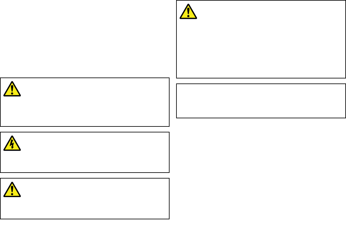
Chapter1:Importantinformation
Applicability
Theinformationinthisbookappliestoallgeographicalareasunless
otherwisestated.
Safetyinformation
Warning:Productinstallationand
operation
Thisproductmustbeinstalledandoperatedin
accordancewiththeinstructionsprovided.Failureto
dosocouldresultinpersonalinjury,damagetoyour
vesseland/orpoorproductperformance.
Warning:Switchoffpowersupply
Ensurethevessel’spowersupplyisswitchedOFF
beforestartingtoinstallthisproduct.DoNOTconnect
ordisconnectequipmentwiththepowerswitchedon,
unlessinstructedinthisdocument.
Warning:Potentialignitionsource
ThisproductisNOTapprovedforusein
hazardous/ammableatmospheres.DoNOTinstallin
ahazardous/ammableatmosphere(suchasinan
engineroomornearfueltanks).
Warning:Ensuresafenavigation
Thisproductisintendedonlyasanaidtonavigation
andmustneverbeusedinpreferencetosound
navigationaljudgment.Onlyofcialgovernment
chartsandnoticestomarinerscontainallthecurrent
informationneededforsafenavigation,andthe
captainisresponsiblefortheirprudentuse.Itisthe
user’sresponsibilitytouseofcialgovernmentcharts,
noticestomariners,cautionandpropernavigational
skillwhenoperatingthisoranyotherRaymarine
product.
Caution:Powersupplyprotection
Wheninstallingthisproductensurethepowersource
isadequatelyprotectedbymeansofasuitably-rated
fuseorautomaticcircuitbreaker.
RFsafetynotice
RFradiationstatement
AIStransceiversgenerateandradiateradiofrequency(RF)
electromagneticenergy(EME).
Safecompassdistance
Safecompassdistanceis1meterminimumforanycompass.Some
compasstypesmayrequiregreaterdistances.Tobesure,you
shouldlocateyourAISunitasfaraspossiblefromthecompass.
TestyourcompasstoverifyproperoperationwhiletheAISunitis
alsooperating.
Importantinformation7

Generalinformation
Caution:Cleaning
Whencleaningthisproduct:
•DoNOTwipethedisplayscreenwithadrycloth,as
thiscouldscratchthescreencoating.
•DoNOTuseabrasive,oracidorammoniabased
products.
•DoNOTuseajetwash.
EMCinstallationguidelines
Raymarineequipmentandaccessoriesconformtotheappropriate
ElectromagneticCompatibility(EMC)regulations,tominimize
electromagneticinterferencebetweenequipmentandminimizethe
effectsuchinterferencecouldhaveontheperformanceofyour
system
CorrectinstallationisrequiredtoensurethatEMCperformanceis
notcompromised.
ForoptimumEMCperformancewerecommendthatwherever
possible:
•Raymarineequipmentandcablesconnectedtoitare:
–Atleast1m(3ft)fromanyequipmenttransmittingorcables
carryingradiosignalse.g.VHFradios,cablesandantennas.
InthecaseofSSBradios,thedistanceshouldbeincreased
to7ft(2m).
–Morethan2m(7ft)fromthepathofaradarbeam.Aradar
beamcannormallybeassumedtospread20degreesabove
andbelowtheradiatingelement.
•Theproductissuppliedfromaseparatebatteryfromthatused
forenginestart.Thisisimportanttopreventerraticbehavior
anddatalosswhichcanoccuriftheenginestartdoesnothave
aseparatebattery.
•Raymarinespeciedcablesareused.
•Cablesarenotcutorextended,unlessdoingsoisdetailedin
theinstallationmanual.
Note:Whereconstraintsontheinstallationpreventanyof
theaboverecommendations,alwaysensurethemaximum
possibleseparationbetweendifferentitemsofelectrical
equipment,toprovidethebestconditionsforEMCperformance
throughouttheinstallation
Suppressionferrites
Raymarinecablesmaybettedwithsuppressionferrites.These
areimportantforcorrectEMCperformance.Ifaferritehastobe
removedforanypurpose(e.g.installationormaintenance),itmust
bereplacedintheoriginalpositionbeforetheproductisused.
Useonlyferritesofthecorrecttype,suppliedbyRaymarine
authorizeddealers.
Connectionstootherequipment
Requirementforferritesonnon-Raymarinecables
IfyourRaymarineequipmentistobeconnectedtootherequipment
usingacablenotsuppliedbyRaymarine,asuppressionferrite
MUSTalwaysbeattachedtothecableneartheRaymarineunit.
Declarationofconformity
RaymarineLtd.declaresthatthisproductiscompliantwiththe
essentialrequirementsofEMCdirective2004/108/EC.
TheoriginalDeclarationofConformitycerticatemaybeviewedon
therelevantproductpageatwww.raymarine.com.
8AIS350/AIS650Installationinstructions

Productdisposal
DisposeofthisproductinaccordancewiththeWEEEDirective.
TheWasteElectricalandElectronicEquipment(WEEE)
Directiverequirestherecyclingofwasteelectricalandelectronic
equipment.WhilsttheWEEEDirectivedoesnotapplytosome
Raymarineproducts,wesupportitspolicyandaskyoutobeaware
ofhowtodisposeofthisproduct.
Warrantyregistration
ToregisteryourRaymarineproductownership,pleasevisit
www.raymarine.comandregisteronline.
Itisimportantthatyouregisteryourproducttoreceivefullwarranty
benets.Yourunitpackageincludesabarcodelabelindicatingthe
serialnumberoftheunit.Youwillneedthisserialnumberwhen
registeringyourproductonline.Youshouldretainthelabelforfuture
reference.
IMOandSOLAS
Theequipmentdescribedwithinthisdocumentisintendedforuse
onleisuremarineboatsandworkboatsnotcoveredbyInternational
MaritimeOrganization(IMO)andSafetyofLifeatSea(SOLAS)
CarriageRegulations.
Technicalaccuracy
Tothebestofourknowledge,theinformationinthisdocumentwas
correctatthetimeitwasproduced.However,Raymarinecannot
acceptliabilityforanyinaccuraciesoromissionsitmaycontain.In
addition,ourpolicyofcontinuousproductimprovementmaychange
specicationswithoutnotice.Asaresult,Raymarinecannotaccept
liabilityforanydifferencesbetweentheproductandthisdocument.
AISdisclaimer
AllinformationpresentedbytheRaymarineAISdeviceisadvisory
only,asthereisariskofincompleteanderroneousinformation.By
placingthisproductintoserviceyouacknowledgethisandassume
completeresponsibilityforanyassociatedrisks,andaccordingly
releaseRaymarineandSRTMarineT echnologyLtdfromanyand
allclaimsarisingfromtheuseoftheAISservice.
Installationguide
Informationscope
Thisdocumentgivesintroductory,installationandtroubleshooting
informationforyourRaymarineAutomaticIdenticationSystem
(AIS)device.
RefertotheproAIS2UserManualandtheoperatingmanualfor
yourRaymarineMultifunctionDisplay,forinstructionsonhowto
congureandoperateyourAISsystem.
AlldocumentsareavailabletodownloadasPDFsfrom
www.raymarine.com
AISoverview
YourAISdeviceusesdigitalradiosignalstoexchange’real-time’
informationbetweenvessels,shorebasedstations,oraidsto
navigation(AToNs)ondedicatedVHFfrequencies.Thisinformation
isusedtoidentifyandtrackvesselsinthesurroundingareaandto
providefast,automaticandaccuratecollisionavoidancedata.
AlthoughAISaugmentsyourradarapplicationbyoperatinginradar
blindspotsanddetectingsmallerAIS-ttedvessels,itdoesnot
replaceradar,asitreliesonreceivingtransmittedAISinformation
andthereforecannotdetectobjectssuchaslandmassesand
navigationalbeacons.
NEVERassumethatAISisdisplayinginformationfromallvessels
inthearea,because:
Importantinformation9
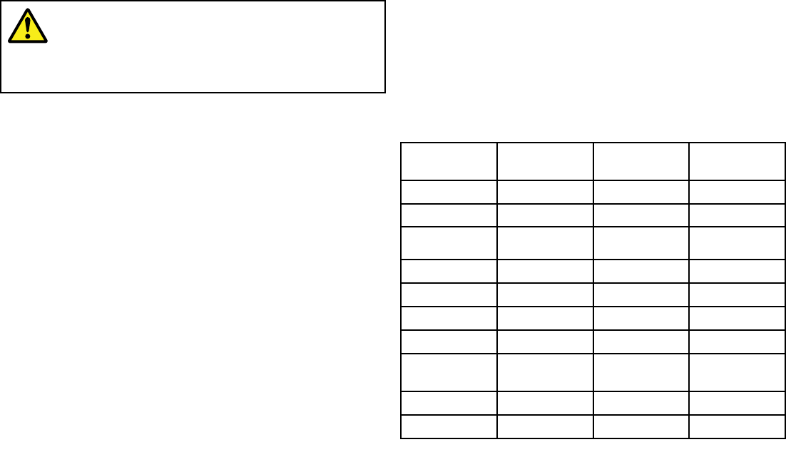
•NotallvesselsarettedwithAIS
•Althoughitismandatoryforlargercommercialvesselstocarry
AIS,itisnotmandatorytouseit.
AISshouldbeusedonlytoaugmentradarinformation,notsubstitute
it.
Warning:AISlimitation
NeverassumethatyourAISisdetectingallvessels
inthearea.Alwaysexercisedueprudenceanddo
notuseAISasasubstituteforsoundnavigational
judgement.
ClassesofAIS
TheAIS350isareceiverthatreceivesmessagesfromvessels,
landbasestations,oraidstonavigation(AT oNs)carryingClassA
orClassBtransceivers.
TheAIS650isaClassBtransceiverthatreceivesmessagesfrom
andtransmitsmessagestovessels,landbasestations,oraidsto
navigation(AT oNs)carryingClassAorClassBtransceivers.
ClassAtransceivers
ClassAAIStransceiverstransmitandreceiveAISsignals.AIS
transceiversarecurrentlymandatoryonallcommercialvessels
exceeding300tonsthattravelinternationally(SOLASvessels).
ThefollowinginformationcanbetransmittedbyaClassAAIS
system:
•Staticdata.Includesinformationsuchasvesselname,vessel
type,MMSInumber,callsign,IMOnumber,length,beamand
GPSantennalocation.
•Voyagerelateddata.Includesinformationsuchasdraft,cargo,
destination,ETAandotherrelevantinformation.
•Dynamicdata.Includesinformationsuchastime(UTC),ship’s
position,COG,SOG,heading,rateofturnandnavigationalstatus.
•Dynamicreports.Ship’sspeedandstatus.
•Messages.Alarmsandsafetymessages.
Rememberthatnotallvesselswilltransmitalloftheinformation.
ClassBtransceivers
ClassBAIStransceiverstransmitandreceiveAISsignals,butuse
areducedsetofdatacomparedtoClassA(seeDataSummary).A
ClassBAIStransceivercanbettedonanyvesselnotttedwitha
ClassAtransceiver,butisnotmandatoryaboardanyvessel.
DataSummary
Data
Receiver
(receive)
Transceiver
(transmit)
Transceiver
(receive)
Ship’snameYesYesYes
TypeYesYesYes
CallsignYesYesYes
IMOnumberYesNoYes
LengthandbeamYesYesYes
AntennalocationYesYesYes
DraftYesNoYes
Cargo
Information
YesYesYes
DestinationYesNoYes
ETAYesNoYes
10AIS350/AIS650Installationinstructions
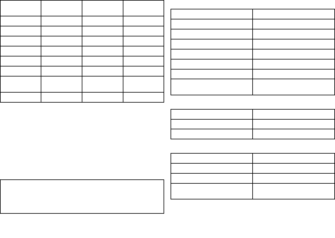
Data
Receiver
(receive)
Transceiver
(transmit)
Transceiver
(receive)
TimeYesYesYes
Ship’spositionYesYesYes
COGYesYesYes
SOGYesYesYes
GyroheadingYesYes*Yes
RateofturnYesNoYes
Navigational
status
YesNoYes
SafetymessageYesNoYes
*ClassBtransceiversdonottransmitaGyroheadingunlessthe
transceiverisreceivinganNMEAHDTsentencefromanexternal
source.
Datareportingintervals
AISinformationisclassedaseitherstaticordynamic.Static
informationisbroadcast,whendatahasbeenamended,orupon
request,orbydefault,every6minutes.
Thereportingratesfordynamicinformationdependonspeedand
coursechange,andaregiveninthefollowingtables.
Note:Thereportingratesshownhereareforreferenceand
maynotbetherateatwhichinformationisactuallyreceivedby
yourAIStransceiver.Thisisdependentonanumberoffactors,
includingbutnotlimitedtoantennaheight,gainandsignal
interference.
ClassAsystems
ShipsDynamicConditionsReportingrate
Atanchorormoored3Minutes
0-14knots10Seconds
0-14knotsandchangingcourse31/3Seconds
14-23knots6Seconds
14-23knotsandchangingcourse2seconds
Fasterthan23knots2seconds
Fasterthan23knotsandchanging
course
2seconds
ClassBsystems
ShipsDynamicConditionsReportingrate
0to2knots3Minutes
Above2knots30Seconds
OtherAISsources
SourceReportingrate
SearchandRescue(SAR)aircraft10seconds
Aidstonavigation3minutes
AISbasestation10secondsor3.33seconds,
dependingonoperatingparameters
Importantinformation11

Systemprotocols
Yourproductcanbeconnectedtovariousproductsandsystemsto
shareinformationandsoimprovethefunctionalityoftheoverall
system.Theseconnectionsmaybemadeusinganumberof
differentprotocols.Fastandaccuratedatacollectionandtransferis
achievedbyusingacombinationofthefollowingdataprotocols:
•SeaT alkng
•NMEA2000
•NMEA0183
Note:Youmayndthatyoursystemdoesnotuseallofthe
connectiontypesorinstrumentationdescribedinthissection.
Seatalkng
SeaTalkng(NextGeneration)isanenhancedprotocolforconnection
ofcompatiblemarineinstrumentsandequipment.Itreplacesthe
olderSeaTalkandSeaTalk2protocols.
SeaTalkngutilizesasinglebackbonetowhichcompatible
instrumentsconnectusingaspur.Dataandpowerarecarriedwithin
thebackbone.Devicesthathavealowdrawcanbepoweredfrom
thenetwork,althoughhighcurrentequipmentwillneedtohavea
separatepowerconnection.
SeaTalkngisaproprietaryextensiontoNMEA2000andtheproven
CANbustechnology.CompatibleNMEA2000andSeaTalk/
SeaTalk2devicescanalsobeconnectedusingtheappropriate
interfacesoradaptorcablesasrequired.
NMEA2000
NMEA2000offerssignicantimprovementsoverNMEA0183,most
notablyinspeedandconnectivity.Upto50unitscansimultaneously
transmitandreceiveonasinglephysicalbusatanyonetime,
witheachnodebeingphysicallyaddressable.Thestandard
wasspecicallyintendedtoallowforawholenetworkofmarine
electronicsfromanymanufacturertocommunicateonacommon
busviastandardizedmessagetypesandformats.
NMEA0183
TheNMEA0183DataInterfaceStandardwasdevelopedby
theNationalMarineElectronicsAssociationofAmerica.Itisan
internationalstandardtoenableequipmentfrommanydifferent
manufacturerstobeconnectedtogetherandshareinformation.
TheNMEA0183standardcarriessimilarinformationtoSeaT alk.
Howeverithastheimportantdifferencethatonecablewillonly
carryinformationinonedirection.ForthisreasonNMEA0183is
generallyusedtoconnectadatareceiverandatransmittertogether,
e.g.acompasssensortransmittingheadingtoaradardisplay.This
informationispassedin‘sentences’,eachofwhichhasathree
lettersentenceidentier.Itisthereforeimportantwhenchecking
compatibilitybetweenitemsthatthesamesentenceidentiersare
usedsomeexamplesofwhichare:
•VTG—carriesCourseandSpeedOverGrounddata.
•GLL—carrieslatitudeandlongitude.
•DBT—carrieswaterdepth.
•MWV—carriesrelativewindangleandwindspeeddata.
NMEAbaudrates
TheNMEA0183standardoperatesatanumberofdifferent
speeds,dependingupontheparticularrequirementorequipment
capabilities.Typicalexamplesare:
•4800baudrate.Usedforgeneralpurposecommunications,
includingFastHeadingdata.
•9600baudrate.UsedforNavtex.
•38400baudrate.UsedforAISandotherhighspeedapplications.
12AIS350/AIS650Installationinstructions

NMEAConnections
YoucanconnectyourtransceivertoyourVHFradiosetand
amultifunctiondisplayusingtheNMEAconnectionsonthe
power/datacable.
Thetransceiver’spoweranddataconnectorprovidesNMEA0183
connectionsatboth4800baudand38400baudrates,asfollows:
WirecolorNMEA0183Function
Yellow4800baudIN—
Gray4800baudIN+
Pink4800baudOUT–
Purple4800baudOUT+
Green38400baudIN—
White38400baudIN+
Blue38400baudOUT—
Brown38400baudOUT+
Amultiplexerbuiltintothetransceivermanagesboth4800and
38400baudrates.ThisfeatureeffectivelyfreesupanNMEAport
onyourmultifunctiondisplay.IfonlyoneNMEA0183portexistson
yourequipment,themultiplexereliminatestheneedforaseparate
multiplexer.
TypicallytheNMEA0183connectionsareusedasfollows:
•The4800baudwiresconnecttotheappropriatepointsonthe
VHFradioorotherNMEA01834800baudinput/outputdevice.
•The38400baudwiresconnecttoappropriateRaymarine
multifunctiondisplay.TheNMEA0183portoneachdisplay
connectedinthismannermustbesetto38400baud.
Importantinformation13

14AIS350/AIS650Installationinstructions

Chapter2:AIS350Receiver
Chaptercontents
•2.1AIS350Receiverunitonpage16
•2.2Planningtheinstallationonpage16
•2.3Cablesandconnectionsonpage19
•2.4Connectionsoverviewonpage20
•2.5VHFconnectiononpage21
•2.6Multifunctiondisplayconnectionsonpage22
•2.7Powerconnectiononpage23
•2.8USBconnectiononpage25
•2.9Locationandmountingonpage26
•2.10Systemchecksonpage27
•2.11Troubleshootingonpage28
•2.12T echnicalspecicationonpage29
AIS350Receiver15
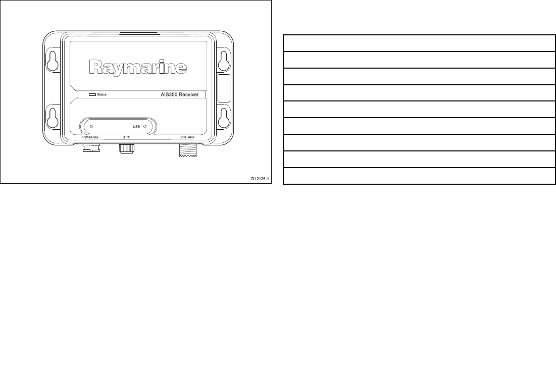
2.1AIS350Receiverunit
AIS 35 0 Re ce ive r
S ta tus
US B
P WR/Da ta S Tng VHF ANT
D12126-1
2.2Planningtheinstallation
Installationchecklist
Installationincludesthefollowingactivities:
InstallationTask
1Planyourinstallation.
2Obtainallrequiredequipmentandtools.
3Mountthesystemcomponents.
4Routeallcables.
5Drillcableandmountingholes.
6Makeallconnectionstoequipment.
7Secureallequipmentinplace.
8Completethepost-installationcheck.
AIS350system
ThefollowingillustrationsshowexamplesofAIS350systems.
16AIS350/AIS650Installationinstructions
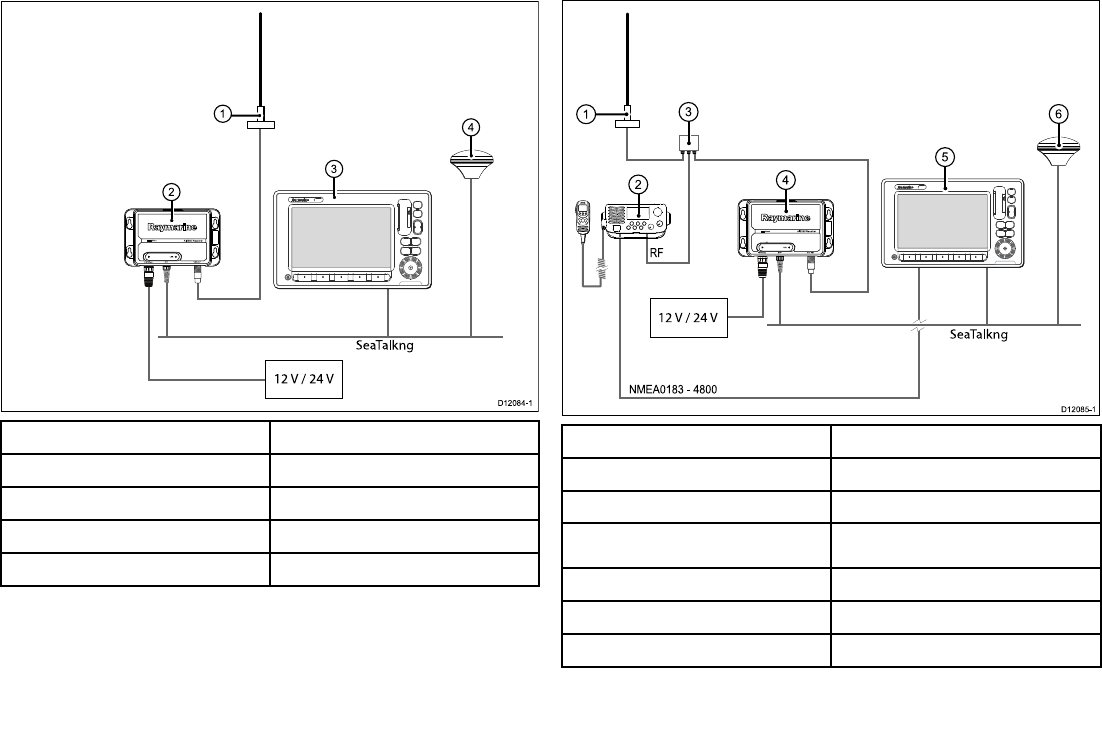
Simplesystemexample
SeaTalkng
12 V / 24 V
AIS350 Rece iver
Status
USB
PWR/Data STng VHF ANT
2
0
1
3
4
D12084-1
ItemDescription
1.VHFantenna
2.AIS350receiverunit
3.Multifunctiondisplay
4.Vessel’sexistingGPSantenna
Extendedsystemexample
NMEA0183 — 4800
RF
12 V / 24 V
AIS350 Rece iver
Status
USB
PWR/Data STng VHF ANT
0
1
2
3
4
D12 0 8 5-1
SeaTalkng
5
6
ItemDescription
1.VHFAntenna
2.VHFRadio
3.VHFSplitter(Notsupplied)
4.AIS350receiverunit
5.Multifunctiondisplay
6.Vessel’sexistingGPSantenna
AIS350Receiver17
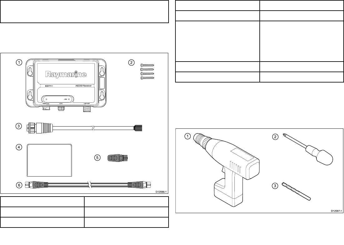
Note:Itisnotrecommendedthatamultifunctiondisplayis
connectedusingbothSeaT alkngandNMEA0183atthesame
time,asdataconictscouldoccur.
Packcontents
TheAIS350modelcontainsthefollowingitems:
12
3
4
5
6
AIS 35 0 R e c e ive r
Sta tu s
USB
PWR /Da ta STng VHF ANT
D12086-1
ItemDescription
1.AIS350receiverunit
2.4xFixingscrews
ItemDescription
3.2mpower/datacable
4.Documentpackcontains:
•Installationinstruction
•SupportsoftwareCD-ROM
•Warrantyregistrationcard
5.SeaTalkngDustcap
6.1mSeaTalkngspurcable
UnpacktheAISunitcarefullytopreventdamage.Savethecarton
andpackingincasetheunithastobereturnedforservice.
Toolsrequired
Toolsrequiredforinstallation
18AIS350/AIS650Installationinstructions
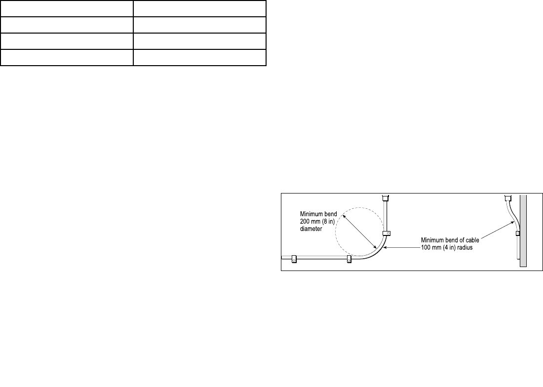
ItemDescription
1.PowerDrill
2.Screwdriver
3.3.2mm(1/8”)drillbit
2.3Cablesandconnections
Generalcablingguidance
Cabletypesandlength
Itisimportanttousecablesoftheappropriatetypeandlength
•Unlessotherwisestateduseonlystandardcablesofthecorrect
type,suppliedbyRaymarine.
•Ensurethatanynon-Raymarinecablesareofthecorrectquality
andgauge.Forexample,longerpowercablerunsmayrequire
largerwiregaugestominimizevoltagedropalongtherun.
Routingcables
Cablesmustberoutedcorrectly,tomaximizeperformanceand
prolongcablelife.
•DoNOTbendcablesexcessively.Whereverpossible,ensurea
minimumbendradiusof100mm.
Minimum bend of cable
100 mm (4 in) radius
Minimum bend
200 mm (8 in)
diameter
•Protectallcablesfromphysicaldamageandexposuretoheat.
Usetrunkingorconduitwherepossible.DoNOTruncables
throughbilgesordoorways,orclosetomovingorhotobjects.
•Securecablesinplaceusingtie-wrapsorlacingtwine.Coilany
extracableandtieitoutoftheway.
•Whereacablepassesthroughanexposedbulkheadordeckhead,
useasuitablewatertightfeed-through.
•DoNOTruncablesneartoenginesoruorescentlights.
AIS350Receiver19
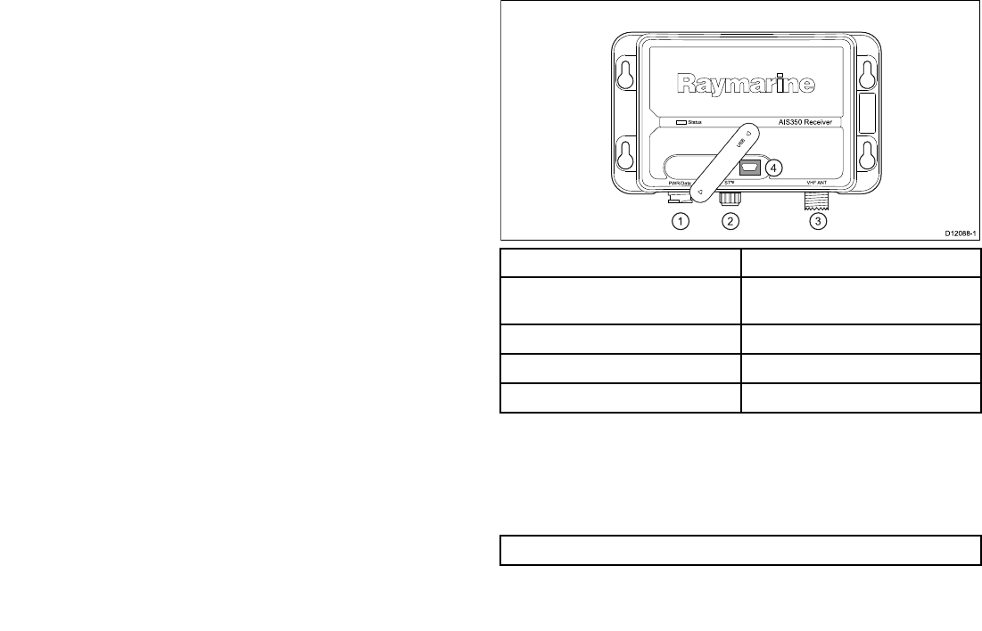
Alwaysroutedatacablesasfarawayaspossiblefrom:
•otherequipmentandcables,
•highcurrentcarryingacanddcpowerlines,
•antennae.
Strainrelief
Ensureadequatestrainreliefisprovided.Protectconnectorsfrom
strainandensuretheywillnotpulloutunderextremeseaconditions.
Circuitisolation
Appropriatecircuitisolationisrequiredforinstallationsusingboth
ACandDCcurrent:
•Alwaysuseisolatingtransformersoraseparatepower-inverter
torunPC’s,processors,displaysandothersensitiveelectronic
instrumentsordevices.
•AlwaysuseanisolatingtransformerwithWeatherFAXaudio
cables.
•Alwaysuseanisolatedpowersupplywhenusinga3rdparty
audioamplier.
•AlwaysuseanRS232/NMEAconverterwithopticalisolationon
thesignallines.
•AlwaysmakesurethatPC’sorothersensitiveelectronicdevices
haveadedicatedpowercircuit.
Cableshielding
Ensurethatalldatacablesareproperlyshieldedthatthecable
shieldingisintact(e.g.hasn’tbeenscrapedoffbybeingsqueezed
throughatightarea).
2.4Connectionsoverview
Thereceiverhasthefollowingconnectiontypes:
Sta tus
P WR/Da ta S Tng VHF ANT
AIS 35 0 Re ce ive r
D12 0 8 8-1
US B
123
4
ItemDescription
1.Power/NMEA0183(4800&38400
baud)/AISSilent
2.SeaTalkng
3.VHFantenna
4.Mini—BUSB(forPCconnectivity)
Carryoutthefollowingprocedurestoconnectupyoureceiver:
•ConnectingVHF
•ConnectingtoMultifunctiondisplay.
•Connectingpower
Note:WiththeUSBcoveropentheunitwillnotbewaterresistant.
20AIS350/AIS650Installationinstructions
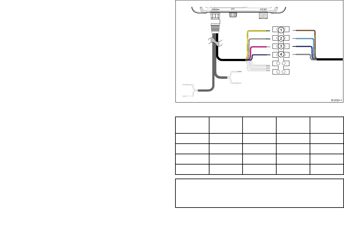
2.5VHFconnection
ConnectupyourAISunittoyourvessel’sVHFconnectionsby
followingthestepsfoundunderConnectingRFandConnecting
NMEA0183(lowbaudrate)below:
ConnectingRF
1.ConnectadedicatedVHFantennadirectlytotheVHFantenna
connectoronyourAISunit,or
2.UsingaVHFsplitter(notincluded)linkyourAISunitinto
theshipsexistingVHFradiosetandantennafollowingthe
instructionsprovidedwiththeVHFsplitter.
ConnectingNMEA0183(lowbaudrate)
ConnecttheAISunit’s4800baudNMEA0183bustothevessel’s
VHFradioasfollows:
1.Identifythe4800baudNMEA0183wiresontheAISunits
power/datacable.
2.Identifythe4800baudNMEA0183wiresonyourVHFset
3.Connectthewiresasshownbelow.
PWR/Da ta S Tng VHF ANT
US B
NMEA0183(lowbaudrate)connectiontoVHF
Item
AISwire
colorAISsignal
VHFwire
colorVHFsignal
1.YellowIN–BrownOUT–
2.GrayIN+BlueOUT+
3.PinkOUT–PurpleIN–
4.PurpleOUT+GrayIN+
Note:ThewirecolorsonyourVHFmaydiffertothatshown
above,ifthisisthecasethenensureyouhaveconnectedthe
correctsignals(e.g.IN—ontheAISconnectstoOUT—onyour
VHFandsoon).
AIS350Receiver21
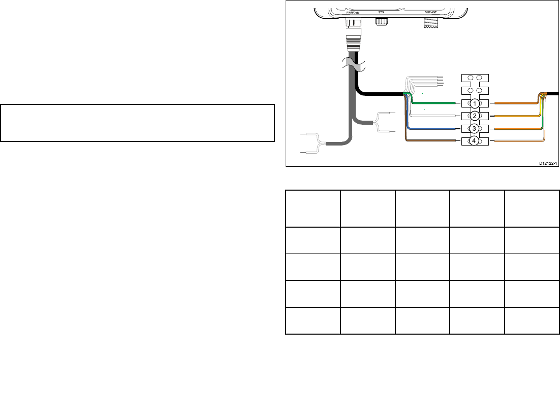
2.6Multifunctiondisplayconnections
YoucanconnectyourAISunittoamultifunctiondisplayusingeither
thededicatedSeaT alkngconnectororNMEA0183(highbaudrate)
viathepower/datacable.
Followthestepsshownineither:
•ConnectingNMEA0183(highbaudrate,or
•ConnectingusingSeaTalkng
Note:Donotconnectyourmultifunctiondisplayusingboth
NMEA0183andSeaTalkngatthesametimeasthiswillcause
dataconicts.
ConnectingNMEA0183(highbaudrate)
IfyourmultifunctiondisplaysareNOTconnectedtoaSeaT alkng
system,connecttheAISunit’s38400baud,NMEA0183bustoyour
multifunctiondisplay’s38400baud,NMEA0183wires.
1.Identifythe38400baud,NMEA0183wiresontheAISunits
power/datacable.
2.Identifythe38400baud,NMEA0183wiresonyourmultifunction
display.
3.Connectthewiresasshownbelow.
PWR/Da ta S Tng VHF ANT
US B
NMEA0183(highbaudrate)
Item
AISwire
colorAISsignal
Multifunc-
tiondisplay
wirecolor
Multifunc-
tiondisplay
signal
1.GreenIN–Orangeand
brown
OUT–
2.WhiteIN+Orangeand
yellow
OUT+
3.BlueOUT–Orangeand
green
IN–
4.BrownOUT+Orangeand
white
IN+
22AIS350/AIS650Installationinstructions
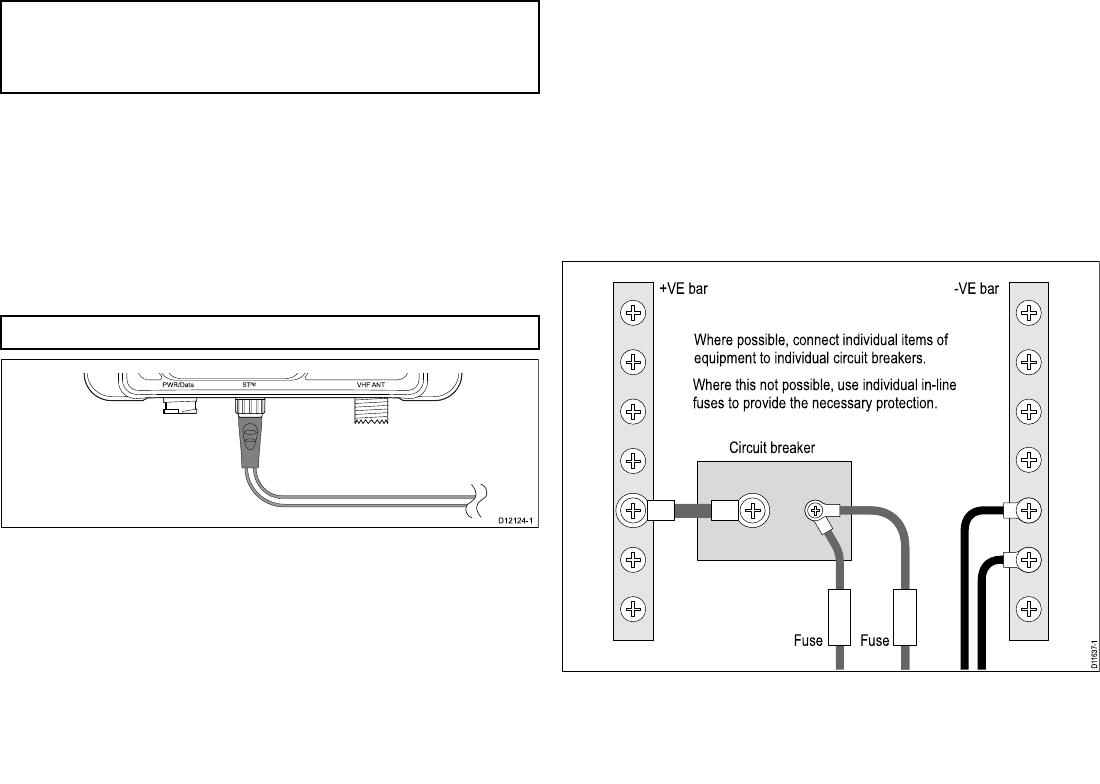
Note:ThewirecolorsonyourMultifunctiondisplaymaydiffer
tothatshownaboveifthisisthecasethenensureyouhave
connectedthecorrectsignals(e.g.IN—ontheAISconnectsto
OUT—onyourMultifunctiondisplayandsoon).
ConnectingSeaTalkng
TheSeaT alkngconnectorenablesyoutoconnecttheAISunit,
aboardvesselsonwhichthemultifunctiondisplaysareconnected
viaSeaT alkng.
BeforeconnectingtoSeaTalkng,refertotheSeaTalkngReference
Manual,andensurethatwiththisproductconnected,themaximum
permittedLoadEquivalenceNumber(LEN)valueforthesystemwill
notbeexceeded.
Note:YourAISunithasaSeaT alkngLENvalueof1.
US B
P WR/Da ta S Tng VHF ANT
1.ConnectthesuppliedSeaTalkngspurcabletotheAISunit’s
SeaTalkngconnector.
2.ConnecttheotherendoftheSeaTalkngspurcabletoasuitable
placeonyourvessel’sSeaT alkngnetworkasfollows:
i.ConnectusingSeaT alkng5–wayconnector.
ii.ConnectusingaSeaT alkngT-Piececonnector.
iii.ConnectusingaspareSeaTalkngspuronaSeaTalkng
converter.
2.7Powerconnection
Powersupplyprotection
Alwaysprotectthepowersupplybyconnectingthered(positive)
wiretothesupplyviaa2Afuseorequivalentautomaticcircuit
breaker.
Sharingabreaker
Wheremorethan1pieceofequipmentsharesabreakeryoumust
provideprotectionfortheindividualcircuits.E.g.byconnectingan
in-linefuseforeachpowercircuit.
D11637-1
+VE bar
Circuit breaker
FuseFuse
-VE bar
Where possible, connect individual items of
equipment to individual circuit breakers.
Where this not possible, use individual in-line
fuses to provide the necessary protection.
AIS350Receiver23
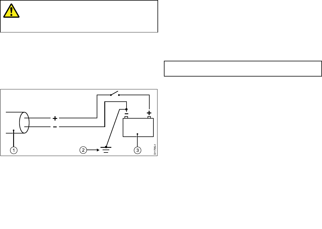
Warning:Productgrounding
Beforeapplyingpowertothisproduct,ensureithas
beencorrectlygrounded,inaccordancewiththe
instructionsinthisguide.
Grounding
ThefollowingrequirementsapplywhengroundingRaymarine
equipmentwhichdoesnothaveadedicateddrainwireorshield:
Commongroundpoint
Thenegativewiremustbeconnectedtoabondedcommonground
point,i.e.withthegroundpointconnectedtobatterynegative,and
situatedascloseaspossibletothebatterynegativeterminal.
1.Powercabletodisplay
2.Bondedcommongroundconnection
3.Battery
Implementation
Ifseveralitemsrequiregrounding,theymayberstbeconnected
toasinglelocalpoint(e.g.withinaswitchpanel),withthispoint
connectedviaasingle,appropriately-ratedconductor,totheboat’s
commonground.
Thepreferredminimumrequirementforthepathtoground(bonded
ornon-bonded)isviaaattinnedcopperbraid,witha30Arating
(1/4inch)orgreater.Ifthisisnotpossible,anequivalentstranded
wireconductormaybeused,ratedasfollows:
•forrunsof<1m(3ft),use6mm2(#10AWG)(6mm)orgreater.
•forrunsof>1m(3ft),use8mm2(#8AWG)orgreater.
Inanygroundingsystem,alwayskeepthelengthofconnecting
braidorwiresasshortaspossible.
Important:DoNOTconnectthisproducttoapositively-grounded
powersystem.
References
•ISO10133/13297
•BMEAcodeofpractice
•NMEA0400
Connectingpower
Theuseofcrimpedandsolderedlugsisrecommended,toprovide
optimumconnectiontothepowersource.
ConnectyourAISunit’spowercabletoeithera12Vdcor24Vdc
powersourceasfollows:
1.Connecttheredwiretothe5Afuseorequivalentautomatic
circuitbreakertothesupplypositiveterminal.
2.Connecttheblackwiretothesupplynegativeterminal.
24AIS350/AIS650Installationinstructions
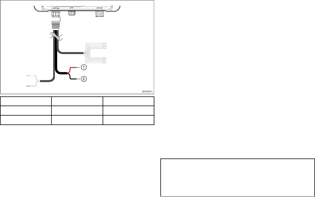
PWR/Da ta S Tng VHF ANT
US B
ItemWirecolorDescription
1.RedPowerSupply+
2.BlackPowersupply–
2.8USBconnection
TheAISunitincludesaMini-BUSBportwhichprovidesPC
connectivity.T oenableconnectionoftheAISunittoaPCtheUSB
drivers,suppliedonthesoftwareCDROMmustbeinstalledonthe
PC
TheUSBportcanbeusedto:
•UseofPCbasedchartingsoftwarewhenconnectedtoAIS.
•Performsoftwareupdate
InstallingUSBdrivers
PriortoconnectingtheAIStoAPCtheUSBdriversmustrstbe
installed.Toinstallfollowthestepsbelow:
1.InsertthesuppliedCDROMandnavigatetotheUSBdrivers
folder.
2.Doubleclickonthesetup.exeletolaunchtheinstaller.
3.Followtheonscreeninstallationinstructionstocomplete
installation.
4.OnceinstalledtheAISunitcanbeconnectedtothePC.The
USBdriverswillbeinstalledautomaticallyandtheAISwill
appearasanewCOMportdevice.
5.SelecttheAISCOMportandabaudrateof38400inPCbased
navigationsoftwaretomakeuseoftheAISdata.
Note:IftheUSBconnectionisremovedfromthePCduring
useyoumustresettheconnectionbeforefurtheruse.T oreset
theconnectiondisconnectthenreapplypowertotheAISbefore
closingandre-launchinganyPCapplicationsusingtheUSB
connection.Finally,reconnecttheUSBcablebetweenthePC
andAISunit.
AIS350Receiver25
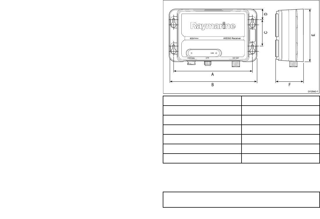
2.9Locationandmounting
Siterequirements
Whenplanningtheinstallation,takethefollowingsiterequirements
intoaccount.
AISrequirement
ThisproductisNOTapprovedforuseinhazardous/ammable
atmospheres.DoNOTinstallinahazardous/ammableatmosphere
(suchasinanengineroomornearfueltanks).
TheAISunitmustbettedinalocationwhereitisnotlikelytobe
steppedonortrippedover,andwhich:
•Iscloseenoughtoallowconnectiontothevessel’sVHFwiththe
3ft(1m)RFcablesupplied.
•Isatleast3ft(1m)fromanengine,compassoranymagnetic
device.
•Hasatleast6in(100mm)ofclearspacebelow,toallowaccess
forcablingandadequatecablebends.
•Ismaintainedatatemperaturebetween-15°C(5°F)and+55°C
(130°F).
Unitdimensions
AIS 35 0 Re ce ive r
S ta tus
US B
P WR/Da ta S Tng VHF ANT
A
B
D12042-1
C
E
D
F
ItemDescription
A.150mm(5.90in)
B.167mm(6.57in)
C.50mm(1.95in)
D.20.3mm(0.8in)
E.99.5mm(3.92in)
F.54mm(2.12in)
Mounting
FittingtheAISunit
Note:T oensurewaterresistancetheunitmustbemounted
verticallywiththeconnectorsfacingdown.
26AIS350/AIS650Installationinstructions
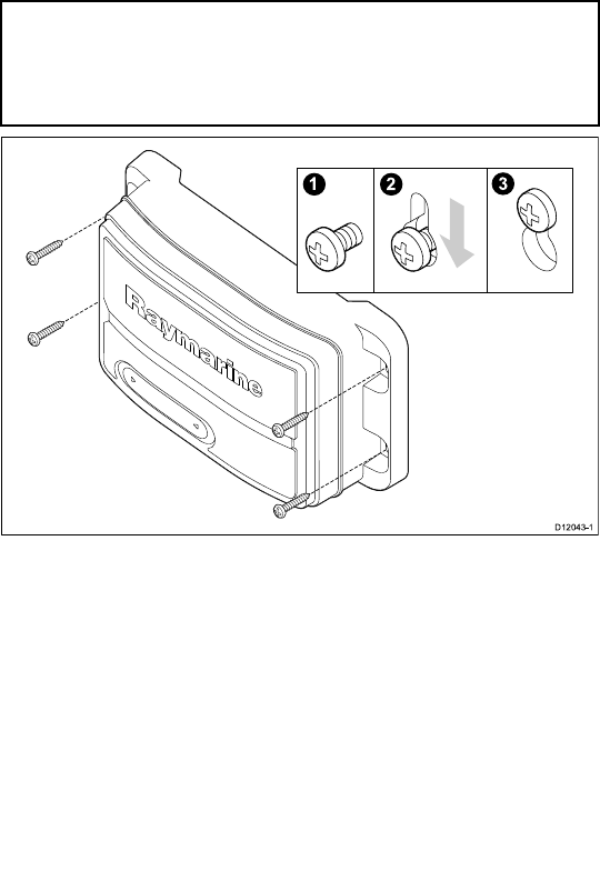
Note:IfyouarettingtheAISunittoberglassthathasagelcoat
surface,overdrillthesurfacetopreventthegelcoatfromdamage
whensecuringthescrews.Beforedrillingthepilotholes,hand
drillthemarkedlocationswithanoversizedbitandcountersink
toapproximately9.5mm(3/8in)diameter.
1.Ensurethattheintendedinstallationsitemeetstheconditions
describedunderSiterequirements.
2.Usingapencil,offeruptheunitandmarkthelocationofthe
screwholesonthemountingsurface.
3.Drillthemountingholesusinga3.2mm(1/8”)drillbit.
4.Parttthescrews.
5.Placetheunitoverthescrewsandmoveunitdowntolockin
position
6.Fullytightenthescrews.
2.10Systemchecks
Switchingon
WhenpoweredontheLEDStatusindicatorshallbebrightgreen
andwilltoggletodimwhenmessagesarereceived.
Whentheinstallationiscomplete,observetheSTATUSindicator
and:
1.SwitchonpowertotheAISreceiver.
2.Checkthat:
i.WhenpoweredontheLEDStatusindicatorshallbebright
GREENandwilltoggletodimGREENwhenmessagesare
received.
Checkingforinterference
Postinstallationcheck
Ifyouhaveinstalledanysystemaboardaboatormadeother
changestotheboat’selectronicsystems(radar,VHFradioetc.),
youneedtocheckbeforecastingoff,thatallelectricalsystems
operatesatisfactorilywithoutanyundueelectricalinterference,
inordertoconformwithElectroMagneticCompatibility(EMC)
regulations.T odothis:
1.Ensuringitissafetodoso,turnonallelectronicsystemsaboard
yourvessel.
2.Checkthattheelectronicsystemsalloperatesatisfactorily.
UsingAIS
TheexactmethodofusingAISdependsonwhichtypeofRaymarine
multifunctiondisplayyouareusing.
Refertothehandbookforyourmultifunctiondisplayforinformation
onusingyourAIS.
AIS350Receiver27

2.11Troubleshooting
IssueAction
NopowerCheck:
•Allpowerconnections
•Checkrelevantfuses
•Thatpowersupplyisatthecorrectvoltage(12Vor24V)
NodataCheckthat:
•Connectionsaresecurethroughoutthesystem
•TheVHFantennaleadissecurelyconnected.
NovesseldataAttherelevantRaymarinemultifunctiondisplay:
•Placethecursoroverthetargetedvesselandensure
theAISDATAsoftkeyisnotsettoOFF
•EnsuretheAISlayerissettoON
•EnsuredisplayedtargettypesaresettoALL
NoAISdataChecktheNMEAand/orSeaTalkngoutputfromthe
multifunctiondisplaystothetransceiverinput,andensure:
•Thewiresarecorrectlyconnected
•ThebaudrateforNMEAis38400baud
NMEA2000Sentences
ThereceiversupportsthefollowingParameterGroupnumbers
(PGNs).
PGNTitleSupported
129038ClassApositionreport●
129039ClassBpositionreport●
129793AISUTCanddatereport●
129794AISclassAstaticand
voyagerelateddata
●
129802AISbroadcastsafety
message
●
129041AtoNpositionreport●
129809AISclassBstaticdata
partA
●
129810AISclassBstaticdata
partB
●
126996Productinfo●
059904ISOrequest●
059392ISOacknowledge●
060928ISOaddressclaim●
065240ISOaddresscommand●
126208NMEAgroupfunctions●
28AIS350/AIS650Installationinstructions

2.12Technicalspecication
Receiverspecication
WaterproongIPX2
Operatingtemperaturerange-15˚Cto+55˚C(5˚Fto131˚F)
Storagetemperaturerange-20˚Cto+75˚C(-4˚Fto167˚F)
HumidityUpto93%at40˚C(104˚F)
Nominalsupplyvoltage12Vto24Vdc,
Operatingvoltagerange9.6Vto31.2Vdc(ratedsupply-20%,
+30%)
Peakcurrentinnormaloperation<200mA
Averagepowerconsumption<2W
LEN(RefertoSeaTalkngreference
manualforfurtherinformation)
1
Fuse/BreakersIn-linefuse
•2A
Receivers2receivers
Receiverband1161.975MHzxedchannel
Receiverband2162.025MHzxedchannel
Receiversensitivity–107dBm
Weight280grams
Connectors•VHFAntenna—SO-239co–axial
connector
•SeaTalkng
•NMEA0183HS—strippedwires
•NMEA0183LS—strippedwires
•Power—strippedwires
•AISsilent—strippedwires
•USB—NMEA0183
AIS350Receiver29

30AIS350/AIS650Installationinstructions

Chapter3:AIS650ClassBtransceiver
Chaptercontents
•3.1AIS650ClassBtransceiverunitonpage32
•3.2Staticdatarequirementonpage32
•3.3RequirementsforUSA&Canadaonpage33
•3.4RequirementsforareasoutsideofUSA&Canadaonpage36
•3.5Planningtheinstallationonpage37
•3.6Cablesandconnectionsonpage40
•3.7Connectionsoverviewonpage41
•3.8GPSantennaconnectiononpage42
•3.9VHFconnectiononpage43
•3.10Multifunctiondisplayconnectionsonpage44
•3.11AISSilentmodeconnectiononpage45
•3.12Powerconnectiononpage46
•3.13USBconnectiononpage48
•3.14InstallingproAIS2andUSBdriversonpage49
•3.15SDCardconnectiononpage49
•3.16Locationandmountingonpage50
•3.17Systemchecksonpage54
•3.18Diagnosticsonpage56
•3.19Troubleshootingonpage56
•3.20T echnicalspecicationonpage58
AIS650ClassBtransceiver31
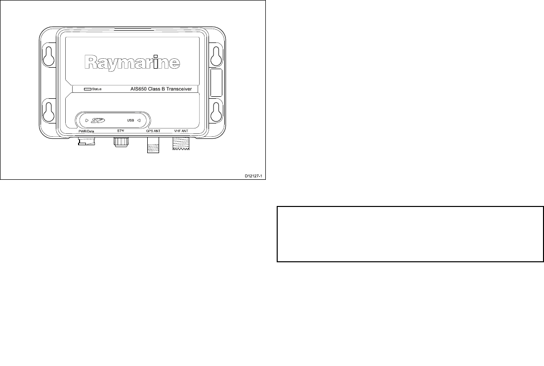
3.1AIS650ClassBtransceiverunit
Sta tus
P WR/Da ta S Tng VHF ANT
AIS 6 50 Clas s B Tra n s c e ive r
GP S ANT
US B
D12127-1
3.2Staticdatarequirement
TheAIStransceiverneedstobecorrectlyprogrammedwiththe
followingvesseldata(staticdata)beforeuse:
•VesselMaritimeMobileServiceIdentity(MMSI)number
•Vesselname
•Vesselcallsign
•VesseldimensionsincludingAISGPSantennalocation
•Vesseltype
AMMSInumbercomprises9digits,andafull,valid9digitvalue
mustbeenteredinordertobeacceptedduringsetup.Anynumber
thatdoesnotmeetthesecriteriawillnotbeacceptedbythesystem.
Allotherelds(i.e.vesseltype,nameetc.)areoptional.
IfyourvesselalreadyhasanMMSInumber(usedforaVHFDSC
radio)thenthesameMMSInumbermustbeusedtoprogramthe
transceiver.
IfavalidMMSInumberisnotentered,thedevicewillenterSilent
Modeandwillnottransmit.However,itwillstilloperateasareceiver.
Important:IntheUnitedStatesofAmerica,theMMSIand
StaticDatamustbeenteredonlybyaRaymarinedealeror
otherappropriatelyqualiedinstallerofmarinecommunications
equipmentonboardvessels.TheuserisNOTauthorizedtodo
this.
InEuropeandotherpartsoftheworldoutsideoftheUnitedStates
ofAmerica,theMMSIandStaticDatacanbesetupbytheuser.
Forfurtherdetails,refertotherequirementsfortheareainwhich
youareoperating.
32AIS350/AIS650Installationinstructions

3.3RequirementsforUSA&Canada
Importantinformation
YourAIStransceiverconformstotherelevantFCCrequirements
RaymarineAIStransceiverscomplywiththeFederal
CommunicationsCommission(FCC)andIndustryCanada
requirementsthatregulatemarineAISandVHFradiousageforthe
USandCanada,respectively.MarineAISusersintheUSmust
complywithallapplicableFCCrulesandregulations,someofwhich
aredescribedinthishandbook.Thisinformationwascurrentatthe
timethishandbookwasprinted.Up-todateinformation,including
licensingrequirements,canbeobtainedontheFCCwebsiteat:
www.fcc.gov/wtb/marine
OfcialFCCformscanbeobtainedontheFCCwebsiteat:
www.fcc.gov/formpage.html
FCCNotice
Compliancestatement
Note:Thisequipmenthasbeentestedandfoundtocomply
withthelimitsforaClassBdigitaldevice,pursuanttopart
15oftheFCCRules.Theselimitsaredesignedtoprovide
reasonableprotectionagainstharmfulinterferenceinaresidential
installation.Thisequipmentgenerates,usesandcanradiate
radiofrequencyenergyand,ifnotinstalledandusedin
accordancewiththeinstructions,maycauseharmfulinterference
toradiocommunications.However,thereisnoguaranteethat
interferencewillnotoccurinaparticularinstallation.Ifthis
equipmentdoescauseharmfulinterferencetoradioortelevision
reception,whichcanbedeterminedbyturningtheequipmentoff
andon,theuserisencouragedtotrytocorrecttheinterference
byoneormoreofthefollowingmeasures:
•Reorientorrelocatethereceivingantenna.
•Increasetheseparationbetweentheequipmentandreceiver.
•Connecttheequipmentintoanoutletonacircuitdifferentfrom
thattowhichthereceiverisconnected.
•ConsultyourRaymarinedealer.
Thisdevicecomplieswithpart15oftheFCCRules.Operationis
subjecttothefollowingtwoconditions:
1.Thisdevicemaynotcauseharmfulinterference,and
2.Thisdevicemustacceptanyinterferencereceived,including
interferencethatmaycauseundesiredoperation.
Changesormodicationstothisequipmentnotexpresslyapproved
inwritingbyRaymarineIncorporatedcouldviolatecompliance
withFCCrulesandvoidtheoperator’sauthoritytooperatethe
equipment.
AIS650ClassBtransceiver33

LeprésentappareilestconformeauxCNRd’IndustrieCanada
applicablesauxappareilsradioexemptsdelicence.L’exploitation
estautoriséeauxdeuxconditionssuivantes:
1.l’appareilnedoitpasproduiredebrouillage,et
2.l’utilisateurdel’appareildoitacceptertoutbrouillage
radioélectriquesubi,mêmesilebrouillageestsusceptibled’en
compromettrelefonctionnement.
StationLicence
FCCstationlicenserequirement
AnFCCShipRadioStationLicenseandCallSignarenotrequired
formostrecreationalvesselstravellinginUSwaters.However,you
mustobtainalicenseifyourvesseltravelstoforeignports.
ShipsthatuseMF/HFsingleside-bandradio,satellite
communications,ortelegraphymustbelicensedbytheFCC.You
canobtainaStationLicensebylingFCCForm605,whichis
availablefromtheFCCwebsitelistedabove.
OperatorLicense
FCCoperatorlicenserequirement
AnOperatorLicenseisnotrequiredtooperateaClassBAIS
TransceiverwithinUSterritorialwaters.However,alicenseis
requiredtooperatethetransceiverifyoudockinaforeignport
(includingCanadaandMexico)orleaveaforeignporttodockina
US.port.YoucanrequestaRestrictedRadiotelephoneOperator
PermitfromtheFCCbylingForm753.
IndustryCanada
IndustryCanadalicenserequirement
ThisClassBAISdigitalapparatuscomplieswithCanadian
ICES-003.
CetappareilnumériquedelaclasseBAISestconformeàlanorme
NMB-003duCanada.
Youdonotneedalicensetooperatethisproductwithinsovereign
watersofCanadaortheUS.Y ouwillneedalicensetooperate
thisradiooutsideofCanadaortheUS.ToobtainIndustryCanada
licensinginformation,contactthenearesteldorregionalofce,
orwrite:
IndustryCanadaRadioRegulatoryBranch
Attention:DOSP
300SlaterStreet
Ottawa,Ontario
Canada,KIAOC8
AIS650Certicationdetails
Thefollowinginformationabouttheradioisrequiredtocomplete
licenseapplications:
•IndustryCanadaCerticationNumber:IC:4069B-AIS650
•FCCTypeNumber:FCC:PJ5–AIS650
•FCCTypeAccepted:Parts15and80
•OutputPower:2Watts
•Modulation:GMSK
•FrequencyRange:156.025MHzto162.025MHz
MaritimeMobileServiceIdentity(MMSI)
Anine-digitMaritimeMobileServiceIdentity(MMSI)numberis
requiredtooperatetheAIStransceiver.
34AIS350/AIS650Installationinstructions
Note:YoucanrequestanMMSInumberfromtheFCCwhen
youapplyforaStationLicense.Ifyourvesseldoesnotrequire
alicense,youmayobtainanMMSIbycontactingBoatUS
(www.boatus.com).Onceobtained,youcanprogramtheMMSI
numberintoyourAISdeviceasdescribedinthedocumentation
accompanyingthetransceiver.
ProgrammingtheMMSI&staticdata
Important:IntheUnitedStatesofAmerica,itisaviolationofthe
rulesoftheFederalCommunicationsCommissiontoinputan
MMSIthathasnotbeenproperlyassignedtotheenduserorto
otherwiseinputanyinaccuratedatainthisdevice.TheMMSI
andStaticDatamustbeenteredonlybyaRaymarinedealeror
otherappropriatelyqualiedinstallerofmarinecommunications
equipmentonboardvessels.InstructionsforenteringtheMMSI
andstaticdataaregiveninthedocumentationontheCDROM
suppliedwiththeAIStransceiver.
Oncestaticdatahasbeenprogrammed,youmustnotchange
it.Iftheinformationprogrammedisnolongercorrect,contact
theRaymarinehelpdeskorthedealerorretailerfromwhomyou
purchasedthetransceiver,toarrangereprogramming.
AntennaMounting&EMEExposure
ThissystemhasaMaximumPermissibleExposure(MPE)Radiusof
1.5meters(perOETBulletin65),assumingthemaximumpowerof
theradioandantennaswithamaximumgainof3dBi.Accounting
fortheheightofanaverageadult(2meters)theminimumheight
oftheantennaabovethedecktomeetRFexposurecompliance
requirementsis3.5meters.Donotoperatethetransceiverwhen
anyoneiswithintheMPEradiusoftheantenna,unlessshielded
fromtheantennaeldbyagroundedmetallicbarrier.
Warning:MaximumPermissible
Exposure
Failuretoobservetheseguidelinesmayexposethose
withinthemaximumpermissibleexposure(MPE)
radiustoRFradiationabsorptionthatexceedsthe
FCCMPElimit.Itistheradiooperator’sresponsibility
toensurethatnoonecomeswithinthisradius.
Foroptimalradioperformanceandminimalhuman
exposuretoradiofrequencyelectromagneticenergy,
makesuretheantennais:
•connectedtotheradiobeforetransmitting
•locatedwhereitwillbeawayfrompeople
•locatedatleast1.5meters(5feet)fromtheradio’s
mainunit
AIS650ClassBtransceiver35

3.4Requirementsforareasoutsideof
USA&Canada
MaritimeMobileServiceIdentity(MMSI)
Anine-digitMaritimeMobileServiceIdentity(MMSI)numberis
requiredtooperateyourAISTransceiver.Insomeareas,aradio
operatorlicenceisrequiredbeforeanMMSInumberwillbeissued.
YoucanrequestanMMSInumberfromsameagencythatissues
radioorShipRadiolicencesinyourarea.Onceobtained,youcan
programtheMMSInumberintoyourAISTransceiverasdescribed
inthedocumentationontheCDROMsuppliedwithyourproduct.
AntennaMounting&EMEExposure
Foroptimalradioperformanceandminimalhumanexposureto
radiofrequencyelectromagneticenergy,makesuretheantennais:
•connectedtotheradiobeforetransmitting
•properlymounted
•locatedwhereitwillbeawayfrompeople
•locatedatleast1.5metres(5feet)fromtheradio’smainunit
ListofCountries
IntheEuropeanUnion,yourAIStransceivermaybeusedinthe
followingcountries:
AustriaLiechtenstein
BelgiumLithuania
BulgariaLuxembourg
CyprusMalta
CzechRepublicNetherlands
DenmarkNorway
EstoniaPoland
FinlandPortugal
FranceRomania
GermanySlovakia
GreeceSlovenia
HungarySpain
IcelandSweden
IrelandSwitzerland
ItalyTurkey
LatviaUnitedKingdom
36AIS350/AIS650Installationinstructions
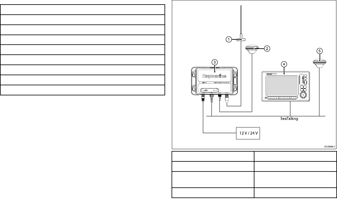
3.5Planningtheinstallation
Installationchecklist
Installationincludesthefollowingactivities:
InstallationTask
1Planyourinstallation.
2Obtainallrequiredequipmentandtools.
3Mountthesystemcomponents.
4Routeallcables.
5Drillcableandmountingholes.
6Makeallconnectionstoequipment.
7Secureallequipmentinplace.
8Completethepost-installationcheck.
AIS650system
ThefollowingillustrationsshowexamplesofAIS650systems.
Simplesystemexample
SeaTalkng
12 V / 24 V
Status
PWR/Da ta STng VHF ANT
AIS650 Clas s B Tra nsce iver
GPS ANT
USB
00
ItemDescription
1.VHFantenna
2.GPSantenna(suppliedwithAIS650
transceiver)
3.AIS650transceiverunit
AIS650ClassBtransceiver37
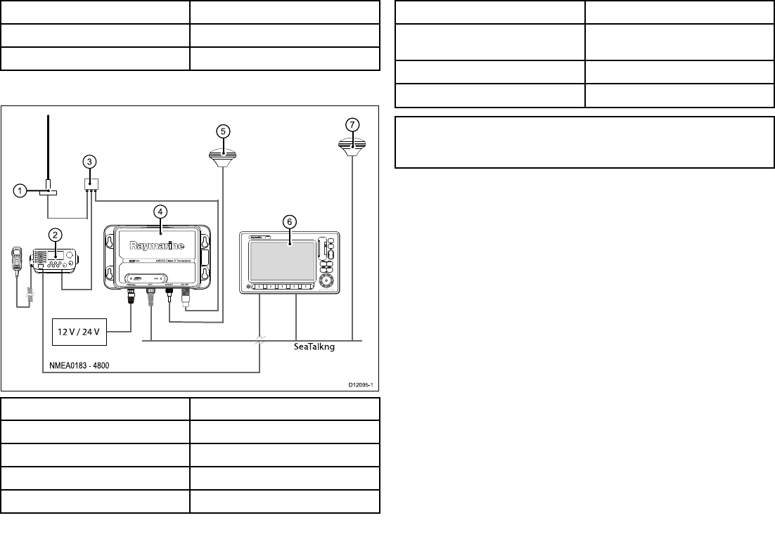
ItemDescription
4.Multifunctiondisplay
5.Vessel’sexistingGPSantenna
Extendedsystemexample
NMEA0183 — 4800
45
2
3
1
Status
PWR/Da ta STng VHF ANT
AIS650 Clas s B Tra nsce iver
GPS ANT
USB
00
4
46
47
12 V / 24 V
SeaTalkng
D12095-1
ItemDescription
1.VHFAntenna
2.VHFRadio
3.VHFSplitter(Notsupplied)
4.AIS650transceiverunit
ItemDescription
5.GPSantenna(suppliedwithAIS650
transceiver)
6.Multifunctiondisplay
7.Vessel’sexistingGPSantenna
Note:AMultifunctiondisplayconnectedtotheAIStransceiver
cannotusetheGPSwhichisconnectedtotheGPSconnection
onAISunit.
38AIS350/AIS650Installationinstructions
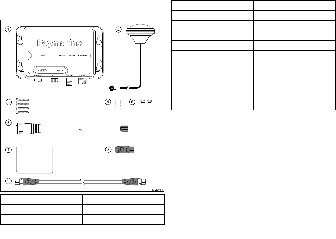
Packcontents
TheAIS650modelcontainsthefollowingitems:
12
345
6
78
9
Sta tus
P WR/Da ta S Tng VHF ANT
AIS 65 0 C la s s B Trans ce ive r
GP S ANT
US B
D12096-1
ItemDescription
1.AIS650transceiverunit
2.GPSantenna(with10mcoaxialcable)
ItemDescription
3.4xFixingscrews
4.2xmountingstuds
5.2xthumbsnuts
6.2mpower/datacable
7.Documentpackcontaining:
•Installationinstruction
•SupportsoftwareCDROM
•Warrantyregistrationcard
8.SeaTalkngDustcap
9.1mSeaTalkngspurcable
UnpacktheunitandGPScarefullytopreventdamage.Savethe
cartonandpackingincasetheunithastobereturnedforservice.
AIS650ClassBtransceiver39
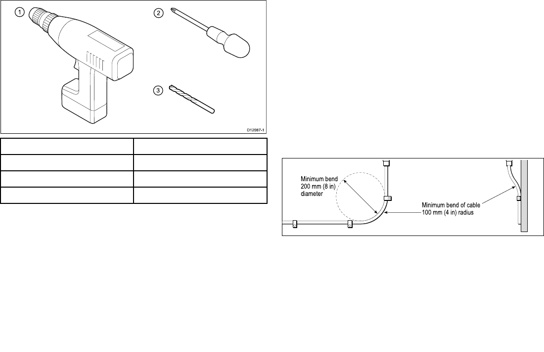
Toolsrequired
Toolsrequiredforinstallation
ItemDescription
1.PowerDrill
2.Screwdriver
3.3.2mm(1/8”)drillbit
3.6Cablesandconnections
Generalcablingguidance
Cabletypesandlength
Itisimportanttousecablesoftheappropriatetypeandlength
•Unlessotherwisestateduseonlystandardcablesofthecorrect
type,suppliedbyRaymarine.
•Ensurethatanynon-Raymarinecablesareofthecorrectquality
andgauge.Forexample,longerpowercablerunsmayrequire
largerwiregaugestominimizevoltagedropalongtherun.
Routingcables
Cablesmustberoutedcorrectly,tomaximizeperformanceand
prolongcablelife.
•DoNOTbendcablesexcessively.Whereverpossible,ensurea
minimumbendradiusof100mm.
Minimum bend of cable
100 mm (4 in) radius
Minimum bend
200 mm (8 in)
diameter
•Protectallcablesfromphysicaldamageandexposuretoheat.
Usetrunkingorconduitwherepossible.DoNOTruncables
throughbilgesordoorways,orclosetomovingorhotobjects.
•Securecablesinplaceusingtie-wrapsorlacingtwine.Coilany
extracableandtieitoutoftheway.
•Whereacablepassesthroughanexposedbulkheadordeckhead,
useasuitablewatertightfeed-through.
•DoNOTruncablesneartoenginesoruorescentlights.
40AIS350/AIS650Installationinstructions
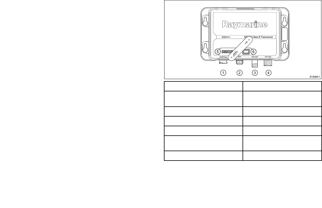
Alwaysroutedatacablesasfarawayaspossiblefrom:
•otherequipmentandcables,
•highcurrentcarryingacanddcpowerlines,
•antennae.
Strainrelief
Ensureadequatestrainreliefisprovided.Protectconnectorsfrom
strainandensuretheywillnotpulloutunderextremeseaconditions.
Circuitisolation
Appropriatecircuitisolationisrequiredforinstallationsusingboth
ACandDCcurrent:
•Alwaysuseisolatingtransformersoraseparatepower-inverter
torunPC’s,processors,displaysandothersensitiveelectronic
instrumentsordevices.
•AlwaysuseanisolatingtransformerwithWeatherFAXaudio
cables.
•Alwaysuseanisolatedpowersupplywhenusinga3rdparty
audioamplier.
•AlwaysuseanRS232/NMEAconverterwithopticalisolationon
thesignallines.
•AlwaysmakesurethatPC’sorothersensitiveelectronicdevices
haveadedicatedpowercircuit.
Cableshielding
Ensurethatalldatacablesareproperlyshieldedthatthecable
shieldingisintact(e.g.hasn’tbeenscrapedoffbybeingsqueezed
throughatightarea).
3.7Connectionsoverview
Thetransceiverhasthefollowingconnectiontypes:
D12 0 9 3-1
1234
Sta tus
P WR/Da ta S Tng VHF ANT
AIS 65 0 Cla s s B Tra n s ce iver
GP S ANT
US B
56
ItemDescription
1.Power/NMEA0183(4800&38400
baud)/AISSilent
2.SeaTalkng
3.GPSantenna
4.VHFantenna
5.SDcard(unitcongurationanddata
recording)
6.Mini-BUSB(forPCconnectivity)
Carryoutthefollowingprocedurestoconnectupyoutransceiver:
•ConnectingGPS
•ConnectingVHF
•ConnectingtoMultifunctiondisplay.
AIS650ClassBtransceiver41

•ConnectingAISSilentwires
•Connectingpower
Note:WiththeSDcard/USBcoveropentheunitwillnotbe
waterresistant.
3.8GPSantennaconnection
TheGPSsuppliedaspartofyourAIStransceiversystemhasa
tted10m(33ft)cabletoconnecttothetransceiver’sGPSantenna
connector.
ConnectthecablefromtheGPSantennatotheGPSconnectoron
theundersideoftheAIStransceiver.
IftheGPSisnotconnected,thetransceiverwilloperateinSilent
Modeandanalarmmessagewillbegenerated.Y oumust
acknowledgeallalarmmessages.Thetransceiverwillnottransmit,
butwillstillreceive.
42AIS350/AIS650Installationinstructions
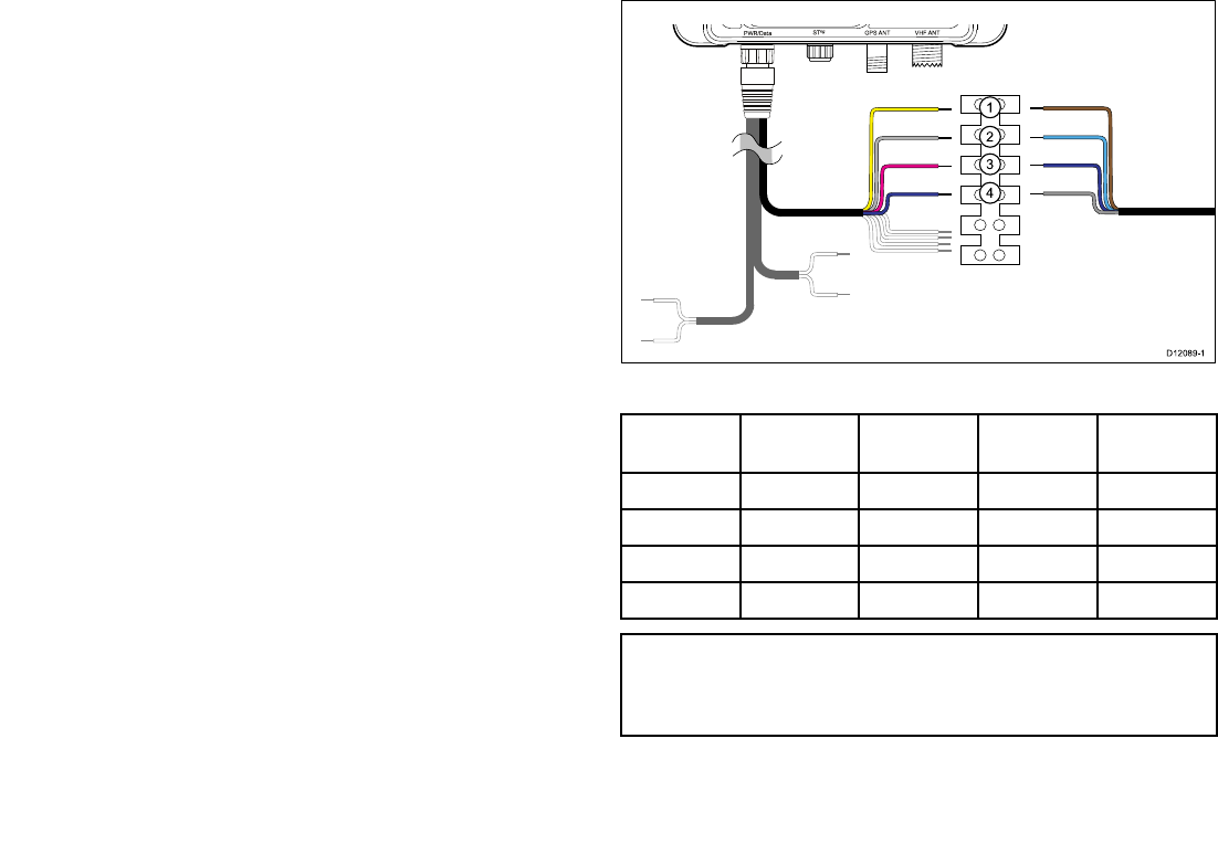
3.9VHFconnection
ConnectupyourAISunittoyourvessel’sVHFconnectionsby
followingthestepsfoundunderConnectingRFandConnecting
NMEA0183(lowbaudrate)below:
ConnectingRF
1.ConnectadedicatedVHFantennadirectlytotheVHFantenna
connectoronyourAISunit,or
2.UsingaVHFsplitter(notincluded)linkyourAISunitinto
theshipsexistingVHFradiosetandantennafollowingthe
instructionsprovidedwiththeVHFsplitter.
ConnectingNMEA0183(lowbaudrate)
ConnecttheAISunit’s4800baudNMEA0183bustothevessel’s
VHFradioasfollows:
1.Identifythe4800baudNMEA0183wiresontheAISunits
power/datacable.
2.Identifythe4800baudNMEA0183wiresonyourVHFset
3.Connectthewiresasshownbelow.
PWR/Da ta S Tng VHF ANT
GP S ANT
US B
NMEA0183(lowbaudrate)connectiontoVHF
Item
AISwire
colorAISsignal
VHFwire
colorVHFsignal
1.YellowIN–BrownOUT–
2.GrayIN+BlueOUT+
3.PinkOUT–PurpleIN–
4.PurpleOUT+GrayIN+
Note:ThewirecolorsonyourVHFmaydiffertothatshown
above,ifthisisthecasethenensureyouhaveconnectedthe
correctsignals(e.g.IN—ontheAISconnectstoOUT—onyour
VHFandsoon).
AIS650ClassBtransceiver43
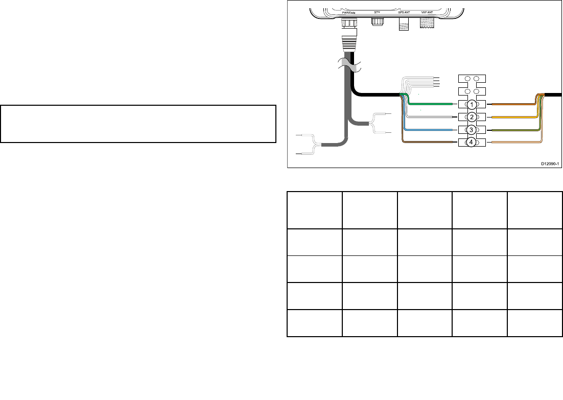
3.10Multifunctiondisplayconnections
YoucanconnectyourAISunittoamultifunctiondisplayusingeither
thededicatedSeaT alkngconnectororNMEA0183(highbaudrate)
viathepower/datacable.
Followthestepsshownineither:
•ConnectingNMEA0183(highbaudrate,or
•ConnectingusingSeaTalkng
Note:Donotconnectyourmultifunctiondisplayusingboth
NMEA0183andSeaTalkngatthesametimeasthiswillcause
dataconicts.
ConnectingNMEA0183(highbaudrate)
IfyourmultifunctiondisplaysareNOTconnectedtoaSeaT alkng
system,connecttheAISunit’s38400baud,NMEA0183bustoyour
multifunctiondisplay’s38400baud,NMEA0183wires.
1.Identifythe38400baud,NMEA0183wiresontheAISunits
power/datacable.
2.Identifythe38400baud,NMEA0183wiresonyourmultifunction
display.
3.Connectthewiresasshownbelow.
PWR/Da ta S Tng VHF ANT
GP S ANT
US B
NMEA0183(highbaudrate)
Item
AISwire
colorAISsignal
Multifunc-
tiondisplay
wirecolor
Multifunc-
tiondisplay
signal
1.GreenIN–Orangeand
brown
OUT–
2.WhiteIN+Orangeand
yellow
OUT+
3.BlueOUT–Orangeand
green
IN–
4.BrownOUT+Orangeand
white
IN+
44AIS350/AIS650Installationinstructions
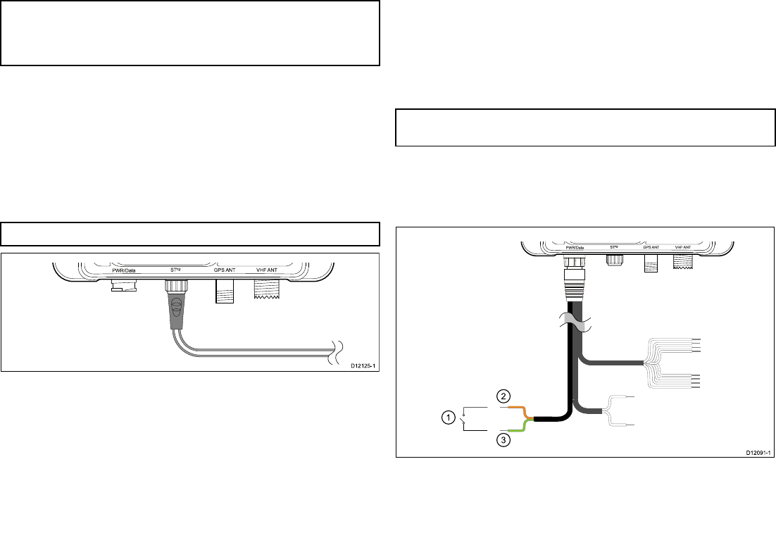
Note:ThewirecolorsonyourMultifunctiondisplaymaydiffer
tothatshownaboveifthisisthecasethenensureyouhave
connectedthecorrectsignals(e.g.IN—ontheAISconnectsto
OUT—onyourMultifunctiondisplayandsoon).
ConnectingSeaTalkng
TheSeaT alkngconnectorenablesyoutoconnecttheAISunit,
aboardvesselsonwhichthemultifunctiondisplaysareconnected
viaSeaT alkng.
BeforeconnectingtoSeaTalkng,refertotheSeaTalkngReference
Manual,andensurethatwiththisproductconnected,themaximum
permittedLoadEquivalenceNumber(LEN)valueforthesystemwill
notbeexceeded.
Note:YourAISunithasaSeaT alkngLENvalueof1.
PWR/Da ta S Tng VHF ANT
GP S ANT
US B
1.ConnectthesuppliedSeaTalkngspurcabletotheAISunit’s
SeaTalkngconnector.
2.ConnecttheotherendoftheSeaTalkngspurcabletoasuitable
placeonyourvessel’sSeaT alkngnetworkasfollows:
i.ConnectusingSeaT alkng5–wayconnector.
ii.ConnectusingaSeaT alkngT-Piececonnector.
iii.ConnectusingaspareSeaTalkngspuronaSeaTalkng
converter.
3.11AISSilentmodeconnection
InadditiontoenablingAISsilentmodeviaaconnectedmultifunction
display.ThePower/datacableontheAISunitincludes2wires
whichcanbeconnectedtoabespokeswitchplacedatasuitable
locationonthevessel’sdashboardtoenablemanualswitchingof
AISsilentmode.
Note:TheAISsilentswitch,wherettedwilloverridea
multifunctiondisplaysAISsilentsetting.
ConnectingAISsilentwires
ToconnectamanualAISsilentswitchtoyoursystemfollowthe
stepsbelow:
PWR/Da ta S Tng VHF ANT
GP S ANT
US B
AIS650ClassBtransceiver45
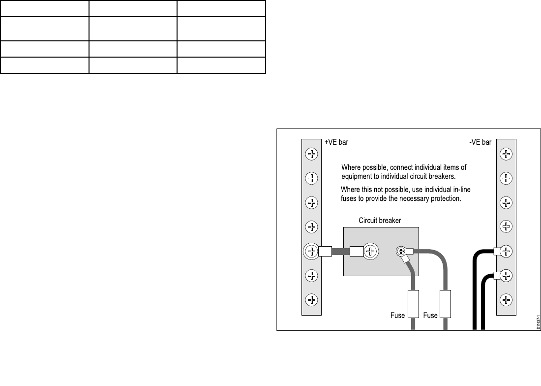
ItemWirecolorSignal/Description
1.—Bespokeswitch
2.OrangeAISSilent+
3.LightGreenAISSilent–
1.RuncablefromswitchlocationtoAISunit.
2.Crimporsolderwireconnectionstotheswitch.
3.CrimporsolderswitchwirestotheorangeandlightgreenAIS
silentwiresonthepower/datacable.
4.Ensurecablesareadequatelyshielded.
3.12Powerconnection
Powersupplyprotection
Alwaysprotectthepowersupplybyconnectingthered(positive)
wiretothesupplyviaa5Afuseorequivalentautomaticcircuit
breaker.
Sharingabreaker
Wheremorethan1pieceofequipmentsharesabreakeryoumust
provideprotectionfortheindividualcircuits.E.g.byconnectingan
in-linefuseforeachpowercircuit.
D11637-1
+VE bar
Circuit breaker
FuseFuse
-VE bar
Where possible, connect individual items of
equipment to individual circuit breakers.
Where this not possible, use individual in-line
fuses to provide the necessary protection.
46AIS350/AIS650Installationinstructions
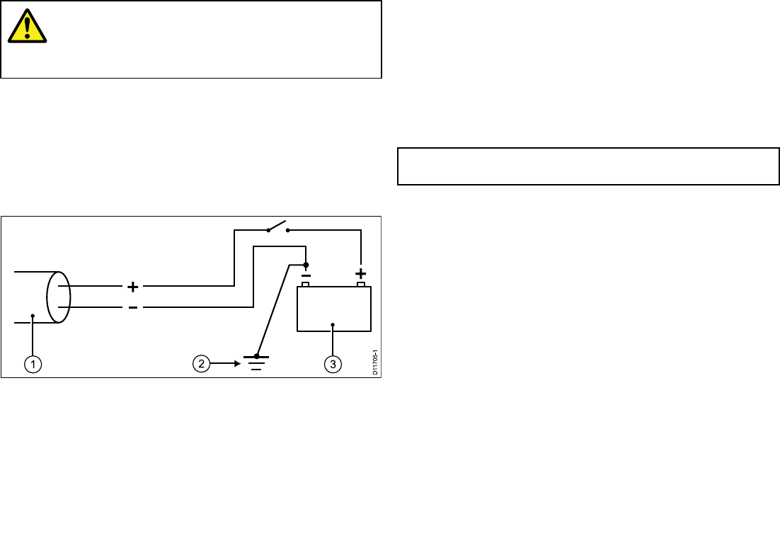
Warning:Productgrounding
Beforeapplyingpowertothisproduct,ensureithas
beencorrectlygrounded,inaccordancewiththe
instructionsinthisguide.
Grounding
ThefollowingrequirementsapplywhengroundingRaymarine
equipmentwhichdoesnothaveadedicateddrainwireorshield:
Commongroundpoint
Thenegativewiremustbeconnectedtoabondedcommonground
point,i.e.withthegroundpointconnectedtobatterynegative,and
situatedascloseaspossibletothebatterynegativeterminal.
1.Powercabletodisplay
2.Bondedcommongroundconnection
3.Battery
Implementation
Ifseveralitemsrequiregrounding,theymayberstbeconnected
toasinglelocalpoint(e.g.withinaswitchpanel),withthispoint
connectedviaasingle,appropriately-ratedconductor,totheboat’s
commonground.
Thepreferredminimumrequirementforthepathtoground(bonded
ornon-bonded)isviaaattinnedcopperbraid,witha30Arating
(1/4inch)orgreater.Ifthisisnotpossible,anequivalentstranded
wireconductormaybeused,ratedasfollows:
•forrunsof<1m(3ft),use6mm2(#10AWG)(6mm)orgreater.
•forrunsof>1m(3ft),use8mm2(#8AWG)orgreater.
Inanygroundingsystem,alwayskeepthelengthofconnecting
braidorwiresasshortaspossible.
Important:DoNOTconnectthisproducttoapositively-grounded
powersystem.
References
•ISO10133/13297
•BMEAcodeofpractice
•NMEA0400
Connectingpower
Theuseofcrimpedandsolderedlugsisrecommended,toprovide
optimumconnectiontothepowersource.
ConnectyourAISunit’spowercabletoeithera12Vdcor24Vdc
powersourceasfollows:
1.Connecttheredwiretothe5Afuseorequivalentautomatic
circuitbreakertothesupplypositiveterminal.
2.Connecttheblackwiretothesupplynegativeterminal.
AIS650ClassBtransceiver47
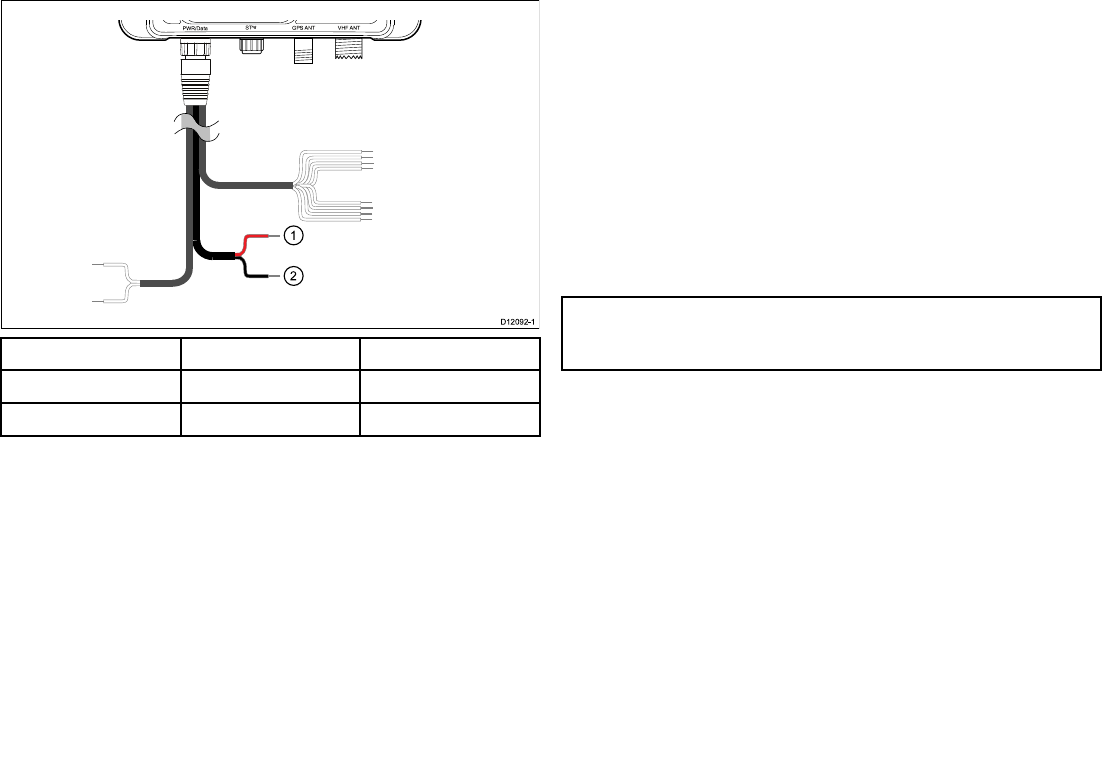
PWR/Da ta S Tng VHF ANT
GP S ANT
US B
ItemWirecolorDescription
1.RedPowerSupply+
2.BlackPowersupply–
3.13USBconnection
TheAISunitincludesaMini-BUSBportwhichprovidesPC
connectivity.T oenableconnectionoftheAISunittoaPCthe
USBdrivers,suppliedonthesoftwareCDROMmustbeinstalled
onthePC.PleasefollowtheInstallingproAIS2andUSBdriver
instructionsbelowtoinstalltheUSBdriversbeforeconnectingthe
AISunittoaPC.
TheUSBportcanbeusedto:
•congurestaticvesseldatausingtheincludedproAIS2software.
•UseofPCbasedchartingsoftwarewhenconnectedtoAIS.
•Performsoftwareupdate
Note:WhenconguringstaticvesseldataviaUSByoudonot
needtopoweruptheAISunit,theUSBshallprovidesufcient
powertocompletethedataconguration.
48AIS350/AIS650Installationinstructions

3.14InstallingproAIS2andUSBdrivers
BeforeconnectingtheAISunittoaPCtheproAIS2applicationand
USBdriversmustbeinstalled.Toinstallfollowthestepsbelow:
1.InsertthesuppliedCDROMandnavigatetotheproAISfolder.
2.Doubleclickonthesetup.exeletolaunchtheinstaller.
3.Followtheonscreeninstallationinstructions,ensuringthatthe
optiontoinstallUSBdriversisselectedwhenpresented.
4.OnceinstalledtheAISunitcanbeconnectedtothePC.The
USBdriverswillbeinstalledautomaticallyandtheAISunitwill
appearasanewCOMportdevice.
5.LaunchproAIS2bynavigatingtotheproAIS2folderaccessible
fromthestartmenu.
6.TheproAIS2usermanualisavailablefromthehelpmenufrom
withintheapplication.
3.15SDCardconnection
TheAISunitincludesamultimediacardreaderwhichallows
connectionofaSDcardupto2GBinsize.
ASDcardcanbeusedto:
•Congurestaticvesseldata.
•Voyagedatalogging.
•Performsoftwareupdate.
Conguringstaticdata
YourdealerorinstallermayprovideaSDcardcontainingstatic
vesselcongurationdataforyourAISunit.T ocongureusingthe
SDcardfollowthestepsbelow:
1.PlacetheSDcard,loadedwithcongurationdataforyourAIS
unitintotheSDcardslot.
2.PowerontheAISunit.
Theunitwillstartupincongurationmode.
3.UponsuccessfulcompletiontheLEDstatusindicatorshallash
GREEN5timesandthecongurationleshallbeerasedfrom
theSDcard.
4.Voyagedatarecordingwillcommenceautomaticallyupon
completionofcongurationprocess
5.IfthecongurationfailstheLEDstatusindicatorshallashRED
5times.
Recordingvoyagedata
TorecordvoyagedatatoSDcardfollowthestepsbelow:
1.InsertablankSDcardintoyourAISunitsSDcardreader.
2.Voyagedataloggingshallcommence.
TheLEDstatusindicatorshallashBLUE2timestoindicate
datalogginghascommenced.
ThefollowingdatashallbeloggedonyourSDcard
AIS650ClassBtransceiver49

•ReceivedAISmessages
•Ownvesselpositionreports
•AISalarmconditions
•AIStextmessages
•GPSposition
TheLEDshallashBLUEevery10secondswhentheSDcardis
full.
Note:Voyagedataloggingshallrecordtothesizelimitofthe
insertedSDcard.
PerformingasoftwareupdateusingaSDcard
ToperformasoftwareupdateusingaSDcardfollowthesteps
below:
1.CopysoftwarelestoyourSDcard.
2.ApplypowertoyourAISunit.
3.Thesoftwareupdatewillnowtakeplace.
3.16Locationandmounting
Siterequirements
Whenplanningtheinstallation,takethefollowingsiterequirements
fortheAIStransceiverandGPSantenna,intoaccount.
AISrequirement
ThisproductisNOTapprovedforuseinhazardous/ammable
atmospheres.DoNOTinstallinahazardous/ammableatmosphere
(suchasinanengineroomornearfueltanks).
TheAISunitmustbettedinalocationwhereitisnotlikelytobe
steppedonortrippedover,andwhich:
•Iscloseenoughtoallowconnectiontothevessel’sVHFwiththe
3ft(1m)RFcablesupplied.
•Isatleast3ft(1m)fromanengine,compassoranymagnetic
device.
•Hasatleast6in(100mm)ofclearspacebelow,toallowaccess
forcablingandadequatecablebends.
•Ismaintainedatatemperaturebetween-15°C(5°F)and+55°C
(130°F).
GPSantennarequirement
AGPSantennaissuppliedwiththetransceiverandmustbe
installedinaccordancewiththeinstructionsgivenhere.DoNOT
connectanyotherGPSantennatothetransceiver.
TheGPSantennacanbemountedeitheronaathorizontalsurface
oronasuitablepole.
•Ifyouintendsurfacemountingtheantenna,ensureyouhave
accesstotheundersideofthemountingsurface.
•Ifyouintendpole-mountingtheantenna,thepoleneedsa1inch
14TPIthread.
50AIS350/AIS650Installationinstructions
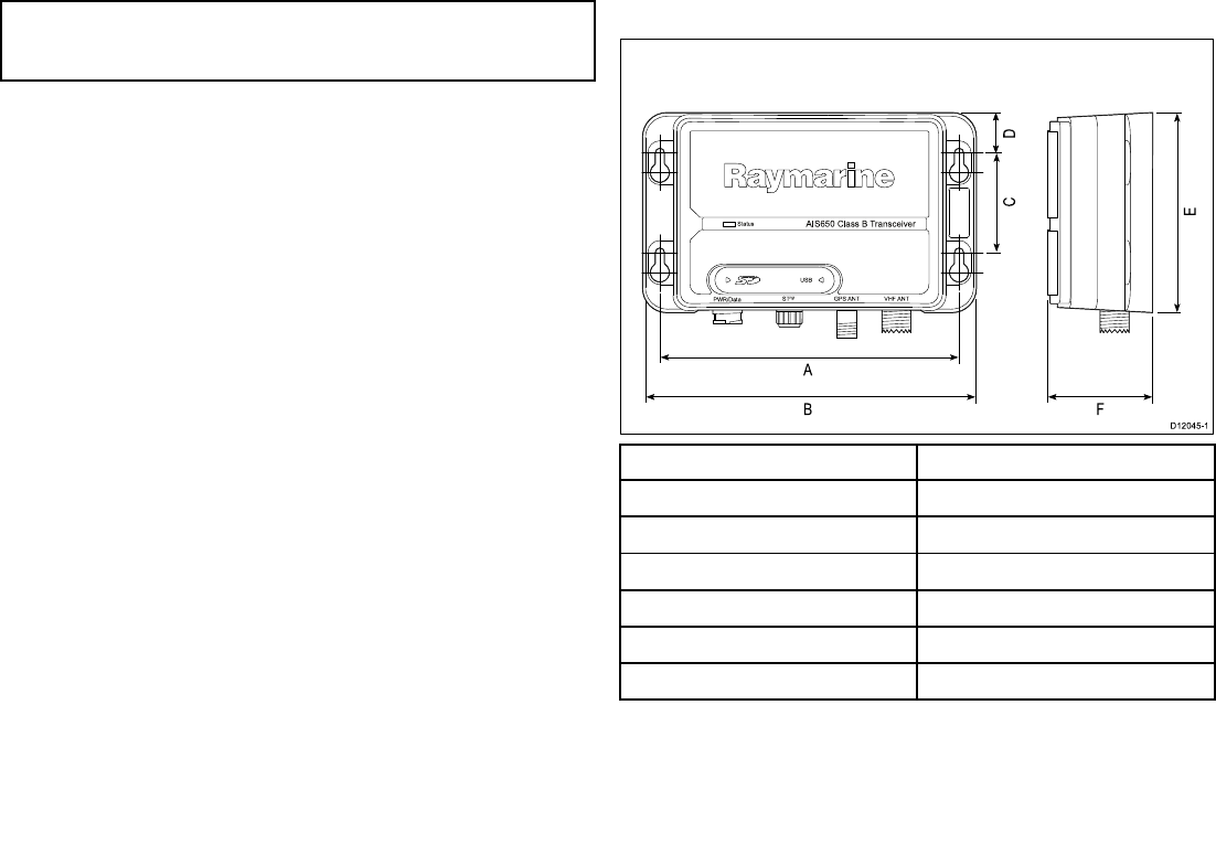
Important:Themainrequirementoftheintendedlocationforthe
GPSantennaisthatitgivesagooddirectlineofsitetotheentire
sky,rightaroundthehorizon.
Ensurethattheintendedmountinglocationis:
•Openandclearofanyobstructions(suchasmasts,searchlights,
orotherstructures)thatcouldblockline-of-sighttothesky.
•Aslowaspossible,tokeeptheantennaasstableaspossible.
Themorestabletheunit,themoreeffectivelyitwilltracksatellites
andprovidestabledata.
•Asfaraspossible(atleast1m(3ft))fromotherantennaeand
electronicequipment.
DoNOTmounttheantenna:
•Inanyareawhereitcouldbesteppedonortrippedover
•Upamast.Thiswillcausetheantennatoswingandgive
signicanterrorsinpositiondata
•Inthedirectpathofaradarbeam.
Unitdimensions
Sta tus
P WR/Da ta S Tng VHF ANT
AIS 65 0 Cla s s B Tra n s ce iver
GP S ANT
US B
A
B
D12 0 4 5-1
C
E
D
F
ItemDescription
A.150mm(5.90in)
B.167mm(6.57in)
C.50mm(1.95in)
D.20.3mm(0.8in)
E.99.5mm(3.92in)
F.54mm(2.12in)
AIS650ClassBtransceiver51
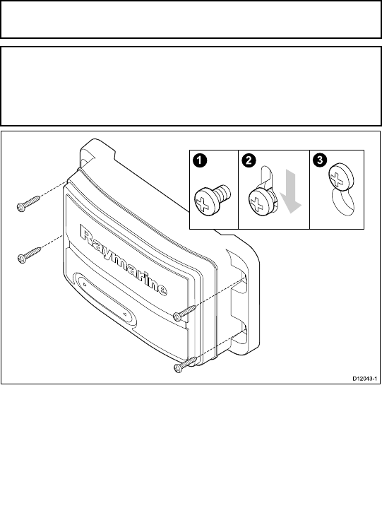
Mounting
FittingtheAISunit
Note:T oensurewaterresistancetheunitmustbemounted
verticallywiththeconnectorsfacingdown.
Note:IfyouarettingtheAISunittoberglassthathasagelcoat
surface,overdrillthesurfacetopreventthegelcoatfromdamage
whensecuringthescrews.Beforedrillingthepilotholes,hand
drillthemarkedlocationswithanoversizedbitandcountersink
toapproximately9.5mm(3/8in)diameter.
1.Ensurethattheintendedinstallationsitemeetstheconditions
describedunderSiterequirements.
2.Usingapencil,offeruptheunitandmarkthelocationofthe
screwholesonthemountingsurface.
3.Drillthemountingholesusinga3.2mm(1/8”)drillbit.
4.Parttthescrews.
5.Placetheunitoverthescrewsandmoveunitdowntolockin
position
6.Fullytightenthescrews.
FittingGPSantenna
TottheGPSantenna:
1.SelectasuitablelocationfortheGPSantennaasdescribed
underSiterequirements.
2.FityourGPSantennausingeithertheSurfacemountingorPole
mountingprocedure,asappropriate.
3.EnsuringtheconditionsinRunningcablesarefullled,runthe
GPSantennacabletotheAIStransceiver.
Surfacemounting
WhensurfacemountingtheGPSantenna,youcanroutethecable
eithercentrally(OptionA)orfromthesideoftheantenna(OptionB).
1.Usethetemplatesuppliedinthishandbooktomarkthetwo
6mm(0.25in)mountingholes.
•OPTIONA:Ifthecableisgoingtopassthroughthemounting
surfacedrilla19mm(0.75in)centerhole.
•OPTIONB:Ifthecableistoberoutedfromthesideofthe
receiver(i.e.abovethemountingsurface),removethetwo
plastictabs(1)obstructingthecablechannel.Ifyoudonot
52AIS350/AIS650Installationinstructions
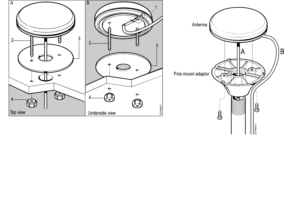
removethesetabsbeforeusingthecablechannel,youcould
damagethecable.
D11638-1
1
23
4
23
4
Top view Underside view
A B
2.Screwthetwomountingstuds(2)intotheundersideofthe
receiver.
3.Stickthesuppliedgasket(3)tothemountingsurface,ensuring
thattheholesonthegasketcorrespondwiththedrilledholes.
4.Routethecableasfollows:
•ForOptionA,feedthecabledownthroughthecenterhole.
•ForOptionB,routethecablealongthecableexitchannel.
5.Carefullyplacethereceiversothemountingstudspassthrough
theholesinthemountingsurface.
6.Securethereceivertothesurfaceusingthetwothumbnuts(4).
Polemounting
Ifyouwanttopole-mounttheGPSantenna,obtainapoleofsuitable
lengthwitha1inch14TPIthread.
D11642-1
A B
Antenna
Pole mount adaptor
1.EnsuringthattheSiterequirementsaremet,securelyattachthe
poletoasuitable,securepoint.
2.RemoveandretainthescrewssecuringtheGPSantennafrom
thepolemountadaptor,thenseparatethesetwoitems.
3.Screwthepolemountadaptorfullyontothepoleandensure
itissecureonthepole.
4.Routetheantennacableasfollows:
i.Ifyouwanttoroutetheantennacabledirectlydownfrom
theantenna(optionA),feeditthroughthecenterofthepole
mountadaptorandthendownthroughthepole.
AIS650ClassBtransceiver53

ii.Ifyouwanttoroutetheantennacableoutofthesideofthe
antenna(optionB),removethetwoplastictabsfromthe
cablechannel,thenfeedthecablealongthechannel.
5.Ensuringyoudonottrapthecable,placetheGPSantennaon
thepolemountadaptorsothescrewholesalign,thensecurethe
antennawiththe2screwsretainedatstep2.
3.17Systemchecks
Switchingon
Whentheinstallationiscomplete,observetheSTATUSindicator
and:
1.SwitchonpowertotheAIStransceiver.
2.Checkthat:
i.Whenpowerisswitchedon,theSTATUSindicatorashes
RED,thenafterafewsecondsgoesAMBER.
Theamberconditioncontinueswhilethetransceiveracquires
aGPSxthentransmitsapositionreport.Thiscantakeup
to2minutes.
ii.Whentherstpositionreporthasbeentransmitted,the
STATUSindicatorgoesGREEN.
Thisconditionremainsallthetimethetransceiverisoperating
normallyandtransmitting.
Conguration
Warning:Congurebeforeuse
ThisRaymarineproductmustbecorrectlycongured,
toensureoptimumperformanceandminimizethe
chancesofunsafeorothererroneousdata.
Congurationrequirement
Afterinstallationandsuccessfulswitchon,theAIStransceivermust
beconguredforoptimumperformanceaboardthevessel.The
personconguringtheAIStransceiverneedstoknowthefollowing
vesselinformation:
•MMSInumber
•Name
•Callsign
54AIS350/AIS650Installationinstructions

•Dimensions
•Type
•GPSantennaposition
Themannerinwhichcongurationiscarriedoutdependsonthe
legalrequirementsofthegeographicalareayouare.
Important:BeforestartinganyAIScongurationprocedure,
SWITCHOFFallassociatedmultifunctiondisplays,otherwiseyou
willnotbeabletocorrectlycongureyourAIStransceiver.
USA
IntheUSA,itisalegalrequirementthatthecongurationis
performedbyasuitabledealer.
YoucanusethesuppliedproAIS2PCsoftware,tocheckthevessel
dataprogrammedintoyourAIStransceiver.Ifthisinformationis
incorrectpleasecontactyourRaymarinedealerbeforeusingthe
transceiver.
AreasoutsideofUSA
InareasoutsideoftheUSA,usethesuppliedproAIS2PCsoftware
tocongureyourAIStransceiver,asdescribedintheproAIS2User
ManualwhichcanbefoundintheproAIS2applicationshelpmenu.
Checkingforinterference
Postinstallationcheck
Ifyouhaveinstalledanysystemaboardaboatormadeother
changestotheboat’selectronicsystems(radar,VHFradioetc.),
youneedtocheckbeforecastingoff,thatallelectricalsystems
operatesatisfactorilywithoutanyundueelectricalinterference,
inordertoconformwithElectroMagneticCompatibility(EMC)
regulations.T odothis:
1.Ensuringitissafetodoso,turnonallelectronicsystemsaboard
yourvessel.
2.Checkthattheelectronicsystemsalloperatesatisfactorily.
UsingAIS
TheexactmethodofusingAISdependsonwhichtypeofRaymarine
multifunctiondisplayyouareusing.
Refertothehandbookforyourmultifunctiondisplayforinformation
onusingyourAIS.
AIS650ClassBtransceiver55

3.18Diagnostics
LEDStatusindicator
LEDStatusindicator
TheLEDSTATUSindicatoronthetransceiverprovidesanindication
ofproductstatus.
ColorStatus
GREENTransceiverisoperatingnormally.
GREENashx5StaticdatacongurationviaSDcard
commenced
AMBEREither:
•Thetransceiverisstartingup,or
•Thetransceiverhasnottransmitted
formorethan2reportingperiods.
ThiscouldbeduetohighAIStrafc
orlossofGPSx.
REDFaultcondition,Refertothe
Troubleshootingsection.
REDashx5StaticdatacongurationviaSDcard
failed
BLUETransceiverisrunninginsilentmode.
BLUEashx2Voyagedatalogginghascommenced
BLUEashevery10secondsSDcardfull(Voyagedatalogging
mode)
3.19Troubleshooting
IssueAction
NopowerCheck:
•Allpowerconnections
•Checkrelevantfuses
•Thatpowersupplyisatthecorrectvoltage(12Vor24V)
AISconguration
dataisnotsaved
Switchoffallassociatedmultifunctiondisplays,then
re-congure
NodataCheckthat:
•Connectionsaresecurethroughoutthesystem
•TheVHFantennaleadissecurelyconnected.
NovesseldataAttherelevantRaymarinemultifunctiondisplay:
•Placethecursoroverthetargetedvesselandensure
theAISDATAsoftkeyisnotsettoOFF
•EnsuretheAISlayerissettoON
•EnsuredisplayedtargettypesaresettoALL
NoAISdataChecktheNMEAand/orSeaTalkngoutputfromthe
multifunctiondisplaystothetransceiverinput,andensure:
•Thewiresarecorrectlyconnected
•ThebaudrateforNMEAis38400baud
56AIS350/AIS650Installationinstructions

Statusindicator
remainsamber
Waitatleast30minutestocheckthata’Quiettime’has
notbeenrequestedbythelocalauthority
Checkthatthe:
•GPSantennaisproperlyconnected
•GPSantennahasaclearviewofthesky,withoutany
obstructions
•MMSInumberhasbeenproperlycongured(usethe
proAISapplication)
Statusindicatoris
red
Checkthat:
•TheVHFantennaisproperlyconnectedandinparticular
itisnotshortcircuitingtothevesselstructure
•Thatpowersupplyisatthecorrectvoltage(12Vor24V)
•TheMMSInumberhasbeenproperlycongured(use
theProAISapplication)
NMEAsentences
ThetransceiversupportsthefollowingParameterGroupnumbers
(PGNs)andsentences.
NMEA2000sentences
PGNTitleTransmitReceive
129038ClassAposition
report
●
129039ClassBposition
report
●
129040ClassBextended
positionreport
●
PGNTitleTransmitReceive
129793AISUTCand
datereport
●
129794AISclassA
staticandvoyage
relateddata
●
129801AISaddress
safetymessages
●
129802AISbroadcast
safetymessage
●
129041AtoNposition
report
●
129809AISclassBstatic
datapartA
●
129810AISclassBstatic
datapartB
●
126996Productinfo●
059904ISOrequest●●
059392ISOacknowledge●
060928ISOaddress
claim
●●
065240ISOaddress
command
●
126208NMEAgroup
functions
●●
AIS650ClassBtransceiver57

NMEA0183sentences
SentenceTitleTransmitReceive
AIVDMReceivedAIS
message
●
AICDOOwnvesselAIS
report
●
AIALRAlarmcondition
state
●
AIACKAlarmacknowl-
edgement
●
DUAIQMMSIqueryand
programming
●
3.20Technicalspecication
Transceiverspecication
WaterproongIPX2
Operatingtemperaturerange-15˚Cto+55˚C(5˚Fto131˚F)
Storagetemperaturerange-20˚Cto+75˚C(-4˚Fto167˚F)
HumidityUpto93%at40˚C(104˚F)
Nominalsupplyvoltage12Vto24Vdc,
Operatingvoltagerange9.6Vto31.2Vdc(ratedsupply-20%,
+30%)
Peakcurrentinnormaloperation2A
Averagepowerconsumption<3W
LEN(RefertoSeaTalkngreference
manualforfurtherinformation)
1
Fuse/BreakersIn-linefuse
•5A
Operatingfrequencyrange156.025MHzto162.025MHz
Channelspacing25KHz
Transmitter1transmitter
Receiversensitivity–107dBm
Receivers2receivers
Weight285grams
58AIS350/AIS650Installationinstructions

Connectors•VHFAntenna—SO-239co-axial
connector
•GPSantenna—TNCco-axial
connector
•SeaTalkng
•NMEA0183HS—strippedwires
•NMEA0183LS—strippedwires
•Power—strippedwires
•AISsilent—strippedwires
•SDcard
•USB—NMEA0183
TransceiverstandardClassBIEC62287-1
GPSreceiverspecication
Receiverchannels50
Nominaltimetorstx36seconds
AIS650ClassBtransceiver59

60AIS350/AIS650Installationinstructions

Chapter4:Technicalsupport
Chaptercontents
•4.1Raymarinecustomersupportonpage62
Technicalsupport61

4.1Raymarinecustomersupport
Raymarineprovidesacomprehensivecustomersupportservice.
YoucancontactcustomersupportthroughtheRaymarinewebsite,
telephoneandemail.Ifyouareunabletoresolveaproblem,please
useanyofthesefacilitiestoobtainadditionalhelp.
Websupport
Pleasevisitthecustomersupportareaofourwebsiteat:
www.raymarine.com
ThiscontainsFrequentlyAskedQuestions,servicinginformation,
e-mailaccesstotheRaymarineT echnicalSupportDepartmentand
detailsofworldwideRaymarineagents.
Telephoneandemailsupport
IntheUSA:
•Tel:+16038815200extension2444
•Email:Raymarine@custhelp.com
IntheUK,Europe,theMiddleEast,orFarEast:
•Tel:+44(0)2392714713
•Email:ukproduct.support@raymarine.com
Productinformation
Ifyouneedtorequestservice,pleasehavethefollowinginformation
tohand:
•Productname.
•Productidentity.
•Serialnumber.
•Softwareapplicationversion.
Youcanobtainthisproductinformationusingthemenuswithinyour
product.
62AIS350/AIS650Installationinstructions

Chapter5:Optionsandaccessories
Chaptercontents
•5.1SeaTalkngcablesandaccessoriesonpage64
•5.2Sparesandaccessoriesonpage65
Optionsandaccessories63

5.1SeaTalkngcablesandaccessories
SeaTalkngcablesandaccessoriesforusewithcompatibleproducts.
DescriptionPartNoNotes
BackboneKitA25062Includes:
•2x5m(16.4ft)
Backbonecable
•1x20m(65.6ft)
Backbonecable
•4xT-piece
•2xBackbone
terminator
•1xPowercable
SeaTalkng0.4m(1.3ft)
spur
A06038
SeaTalkng1m(3.3ft)
spur
A06039
SeaTalkng3m(9.8ft)
spur
A06040
SeaTalkng5m(16.4ft)
spur
A06041
SeaTalkng0.4m(1.3ft)
backbone
A06033
SeaTalkng1m(3.3ft)
backbone
A06034
SeaTalkng3m(9.8ft)
backbone
A06035
DescriptionPartNoNotes
SeaTalkng5m(16.4ft)
backbone
A06036
SeaTalkng20m(65.6ft)
backbone
A06037
SeaTalkngtobareends
1m(3.3ft)spur
A06043
SeaTalkngtobareends
3m(9.8ft)spur
A06044
SeaTalkngtoSeaTalk2
0.4m(1.3ft)spur
A06048
SeaTalkngPowercableA06049
SeaTalkngTerminatorA06031
SeaTalkngT-pieceA06028Provides1xspur
connection
SeaTalkng5–way
connector
A06064Provides3xspur
connections
SeaTalk1toSeaTalkng
converter
E22158
SeaTalkngInline
terminator
A80001
SeaTalkngBlankingplugA06032
64AIS350/AIS650Installationinstructions

5.2Sparesandaccessories
ThefollowingsparesareavailablefortheAISreceiver/transceiver:
PartnumberDescription
R62241GPSantenna—passive(with10m
coaxialcable)—AIS650only
R321622mpower/Datacable
Optionsandaccessories65

66AIS350/AIS650Installationinstructions

www.ra ym a rin e .c o m 0168