Цена по запросу
Нужны дополнительные вводные для просчета цены, закажите звонок или напишите менеджеру в WhatsApp:
Спасибо за заявку
Наш менеджер свяжется с вами в ближайшее время
Узнать цену в WhatsApp
- Наличие
- уточняйте
- Гарантия
- 12
- Самовывоз
-
Тюмень
- Возможна доставка до адреса
-
Способы оплаты
Описание
Характеристики
Файлы

Оформить заказ
Экспертные мнения
Экспертные мнения
Купить Трассоискатель Radiodetection RD8000 PXLM в Тюмени легко — просто позвоните по телефону:: 8-800-551-11-01
-
Contents
-
Table of Contents
-
Troubleshooting
-
Bookmarks
Quick Links
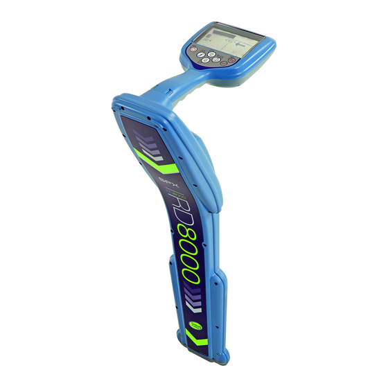
RD8000
Radiodetection’s universal
precision locator.
l
l
Operation Manual
Issue 1
July 2008
90/RD8K-OPMAN-ENG/01
Related Manuals for Radiodetection RD8000
Summary of Contents for Radiodetection RD8000
-
Page 1
RD8000 Radiodetection’s universal precision locator. Operation Manual Issue 1 July 2008 90/RD8K-OPMAN-ENG/01… -
Page 3: Preface
RD8000 product family, including this manual. these objects so proceed with caution. There are also some live cables which the RD8000 will not be able to detect in Power mode. The RD8000 does not indicate Important notices whether a signal is from a single cable or from several in close proximity.
-
Page 4: Special Bluetooth ® Notice
Special Bluetooth notice ® RD8000 locators and transmitters contain a Class 1 device that can emit radio frequency energy Bluetooth ® during the operation of certain product features. While the Bluetooth device is busy, pairing or sending iLOC™ ® commands from the locator to the transmitter, or sending SurveyCERT™…
-
Page 5: Table Of Contents
3.15.1 Adjusting power output 1.1 About this manual 3.15.2 Boost (Tx3 and Tx10 only) 1.1.1 Additional documentation Section 4. – Using SurveyCERT™ 1.2 About the RD8000 4.1 Saving measurements 1.3 Manual outline 4.2 Uploading measurements 1.4 Safety 4.3 Erasing measurements Section 2.
-
Page 6
10.4.1 When to use a sonde 10.4.2 Choosing a suitable sonde 10.4.3 Preparation 10.4.4 Propelling a sonde 10.4.5 Locating and tracing a sonde 10.4.6 Checking sonde depth 10.4.7 Types and range of sondes 10.5 Stethoscopes 10.5.1 When to use a stethoscope iv RD8000 Operation Manual… -
Page 7
Table of figures Figure 2.1: RD8000 receiver Figure 2.2: RD8000 showing Bluetooth ® antenna Figure 2.3: receiver keypad Figure 2.4: receiver LCD Figure 2.5 RD8000 transmitter Figure 2.6: Rechargeable battery pack Figure 2.7: transmitter keypad Figure 2.8 transmitter LCD Table 5.1: Bluetooth error codes ®… -
Page 9: Section 1. — Introduction
RD8000 receiver and transmitter. RD8000 receiver and transmitter system. Before Section 8 introduces depth and current readings. operating the RD8000 system it is very important that you Section 9 provides general locating tips. read this manual, noting all safety warnings and procedures.
-
Page 10: Figure 2.1: Rd8000 Receiver
Figure 2.1: RD8000 receiver Figure 2.3: receiver keypad Figure 2.2: RD8000 showing Bluetooth antenna ® 23 24 25 Figure 2.4: receiver LCD 2 RD8000 Operation Manual…
-
Page 11: Section 2. — System Overview
Indicates the signal strength and peak marker. Signal strength: Numerical indication of signal strength. Peak / Proportional arrows: Indicates the location of the line relative to the receiver. Battery icon: Indicates the battery level. Sensitivity and Log number: Displays the log RD8000 Operation Manual 3…
-
Page 12: Figure 2.5 Rd8000 Transmitter
Figure 2.5 RD8000 transmitter Figure 2.6: Rechargeable battery pack Figure 2.7: transmitter keypad Figure 2.8 transmitter LCD 4 RD8000 Operation Manual…
-
Page 13: Tx1, Tx3 And Tx10 Transmitters
Fault-Find Mode. CD Mode indicator (Tx10 only): Indicates that the transmitter is in Current Direction Mode. Voltage warning indicator: Indicates that the transmitter is outputting potentially hazardous voltage levels. Volume icon: Displays the volume level. RD8000 Operation Manual 5…
-
Page 14: Section 3. — Basic Operation
You can set the working conditions is approximately 30 hours on the system up using the RD8000 menu as described below. receiver and 15 hours on the transmitter. NOTE: These procedures refer to both the transmitter NOTE: Prolonged use of high power output on the and receiver unless stated otherwise.
-
Page 15: Language
3.2.3 Units (receiver only) 3.3.1 Navigating the receiver menu The RD8000 allows you to work in Metric or Imperial (US First power up the receiver. customary) units. Press the key to enter the menu.
-
Page 16: Iloc™ Commands
For more information on iLOC, please refer to Section 6. 3.3.4 Navigating the transmitter menu 3.6 Frequencies First power up the transmitter. The RD8000 supports a very large range of locatable, Press the key to enter the menu. active and passive frequencies. For a complete list…
-
Page 17: Selecting Frequencies
RD8000’s digital signal processor. DOP is an integrated • Greater than 1 meter: depth is displayed in meters. feature of the RD8000. No action is required by the user. • Less than 3 feet: depth is displayed in inches. •…
-
Page 18: Passive Avoidance
3.12 Antenna modes PASSIV mode. Passive avoidance mode is now selected. Perform your The RD8000 receiver supports four antenna modes to survey as required. suit your particular application or the local environment. These modes are: 3.11 StrikeAlert™…
-
Page 19: Backlight
3.15.2 Boost (Tx3 and Tx10 only) Boost allows the transmitter to output its maximum wattage for a specified period of time in minutes. WARNING! The transmitter is capable of outputting potentially lethal wattages. Exercise extreme caution when using Boost. RD8000 Operation Manual 11…
-
Page 20: Section 4. — Using Surveycert
The RD8000 can store up to 1000 measurements in The RD8000 allows you to delete all measurements. memory. Erasing the log will wipe the RD8000 memory and is usually recommended when you begin a new survey. 4.1 Saving measurements WARNING! Erasing measurements cannot be…
-
Page 21: Section 5. — Bluetooth ® Features
5.1 About wireless connections 5.3 Pairing to a PC (SurveyCERT) The RD8000 features a Bluetooth wireless module. All RD8000 models can connect to a compatible PC via ® All RD8000 locators feature as standard the ability to the receiver’s integrated Bluetooth module.
-
Page 22: Pairing To A Pda (Surveycert)
SurveyCERT and click Finish. Outgoing Port with the RD8000. Note the port number of the selected COM port. 5.4 Pairing to a PDA (SurveyCERT) All RD8000 models can connect to a compatible PDA via the receiver’s integrated Bluetooth module. Connecting ®…
-
Page 23: Troubleshooting
800m (in direct line of sight), your PDA (or notebook) code to help you resolve the problem on the receiver. and the RD8000 must be within 10m (30 feet) to maintain The codes are as follows: a wireless connection.
-
Page 24: Section 6. — Iloc
Section 6. – iLOC™ 6.1 About iLOC Pairing: iLOC is a standard feature of the RD8000 PXLB and Once both devices are ready to pair press the PDLB. To use iLOC, the transmitter and receiver must be key on the transmitter and the key on the paired using the procedure in Section 6.2.
-
Page 25: Sidestep
Transmitter power options are located in the TXOUT menu on the receiver. Press and hold the key to display the TXOUT menu. Press the key to enter the TXOUT menu. Scroll through the power output options using the keys; available options are: RD8000 Operation Manual 17…
-
Page 26: Section 7. — Locating Cables And Pipes
This section introduces the principals and techniques of antenna mode, you should then use Null or Peak modes locating buried cable and pipe utilities with the RD8000 to gain a more accurate location as single antenna mode system. For more information on the theory of cable is unable to pinpoint the location of the target line.
-
Page 27: Figure 7.1 Line Tracing
Repeat the steps of the procedure to increase pinpoint accuracy. Periodically switch to peak mode, locate the target line, and verify its exact position. Figure 7.1 Line tracing RD8000 Operation Manual 19…
-
Page 28: Sweep And Search
Figure 7.5: Inductive search may be crossed. Figure 7.4: Passive sweep 20 RD8000 Operation Manual…
-
Page 29
Repeat the search along any other possible paths of lines. Once the positions of any lines have been marked, reverse positions, place the transmitter over and along each line in turn, and trace the line out of the search area. RD8000 Operation Manual 21… -
Page 30: Figure 8.1: Taking A Depth Reading
8.1.1 TruDepth and Compass • Pinpoint the target line accurately with the receiver. It is important to note that the RD8000 will only display • Check the receiver is directly over the line, the depth when the receiver is correctly oriented above the antennae are at right angles to it and the receiver is target line, cable or sonde.
-
Page 31: Verifying Depth Measurements
To reduce the effects of ground coupling the transmitter, when it is placed on the box, must be more than 500mm above the ground Hold the receiver with the blade horizontal and pointing RD8000 Operation Manual 23…
-
Page 32: Figure 8.3: Current Readings
Measuring current provides useful information about the position of bends and intersections. Measuring current after a tee will indicate the main line that pulls more current along its greater length. Figure 8.3: Current readings 24 RD8000 Operation Manual…
-
Page 33: Figure 8.7: Current Readings Using Transmitter
Because current measurement is a function of depth, it is only available in the locating modes. It is also available with Current Direction (CD) clamps. RD8000 Operation Manual 25…
-
Page 34: Section 9. – General Locating Tips
• Avoid applying the signal by induction. The signal may be coupling to more than one line directly from the transmitter. Use the signal clamp where possible. 26 RD8000 Operation Manual…
-
Page 35: Signal Grounding
Connection to the cable sheath applies the transmitter signal for a considerable distance enabling the receiver to trace cables feeding illuminated street furniture as well as other street lights. RD8000 Operation Manual 27…
-
Page 36: Figure 9.5: Making Double-Ended Connections
The long cable should be kept as far away as possible from the expected route of the line. Radiodetection supplies 50 meter and 200 meter extension cables for this purpose. This method of applying the transmitter signal is ideal for positive identification of a target line.
-
Page 37: Figure 10.1: Connecting Clamps
RD4000 accessories. Use clamps to help apply a signal to pipeline Place the clamp around the pipe or cable and or live wire. Use an A-Frame to provide the RD8000 switch the receiver on. receiver with advanced fault-finding capabilities.
-
Page 38: Figure 10.2: Standard Clamp
NOTE: It is not necessary to make a ground connection signals. from the transmitter when using the clamp. WARNING! When clamping around a power cable ensure that the clamp is connected to the transmitter at all times. 30 RD8000 Operation Manual…
-
Page 39: Figure 11.5 Cd Clamp
Sondes used in underground drilling and boring cable connector. operations are normally housed in the boring or drill head behind the boring or drill bit. RD8000 Operation Manual 31…
-
Page 40: Figure 10.6: Sonde Deployment
Move the receiver from side to side until the bar 10.4.6 Checking sonde depth graph indicates a peak. The RD8000 receiver will automatically display the depth Repeat 1, 2 and 3 with the antenna vertical and of a located sonde providing the receiver is correctly resting on or just above the ground.
-
Page 41: Figure 10.9: Standard Sonde
The FlexiTrace can be inserted into a pipe or duct as small as 12 mm/0.5 inch internal diameter with a minimum bend radius of 250mm. Batteries are not required, as the FlexiTrace is powered by the RD8000 transmitter. The FlexiTrace can be used in two modes: Sonde mode or Line mode.
-
Page 42: Stethoscopes
Note: The submersible antenna is calibrated to work at pipes or cables in walls. one frequency. CD stethoscope In restricted areas, the CD stethoscope can be used to obtain current direction but not current measurement. 34 RD8000 Operation Manual…
-
Page 43: Figure 10.13: Using A Submersible Antenna
It may be necessary to use a high power, low frequency tracing signal. It is necessary to define a method of recording target line position and depth before starting work in the boat or on the seabed. Figure 10.13: Using a submersible antenna RD8000 Operation Manual 35…
-
Page 44: Section 11. – Fault-Finding
11.2 Preparation cable is long. Using RD8000 standard locating techniques locate the WARNING! By selecting 8kHz output a high voltage cable for a short distance and trace and mark its route.
-
Page 45: Figure 11.1: Cable Sheath Fault-Finding
Reduce the distance between Soil placing the A-frame spikes in the ground to allow for Path Road the increased distance to the actual fault position. Fault line Figure 11.2: Locating cable sheath faults with the receiver and A-frame RD8000 Operation Manual 37…
-
Page 46: Figure 12.1: Current Direction
NOTE: CD mode is not supported on the RD8000 PXL and PXLB. Figure 12.1: Current direction A signal that has coupled onto adjacent lines finds a return path to the point of the original signal application.
-
Page 47: Figure 12.2: Cd Reset
The direction has shifted from forwards to backwards. At the intermediate point (D) the current flow cannot be determined. At this point the CD arrows on the RD8000 receiver will flash on and off. In the example shown in the…
-
Page 48: Section 13. – Appendices
Centros™ Manager suite. With eCAL Ensure the equipment is clean and dry whenever you can validate your RD8000 receiver against its original possible. factory calibration. Clean this equipment with soft, moistened cloth.
-
Page 49: Specifications For The Receiver And
• • Active 8kHz • • • • Active 9.8kHz • • Active 33kHz • • • • Active 65kHz • • • • Active 83kHz • • • • Active 131kHz • • • • RD8000 Operation Manual 41…
-
Page 50: Supported Accessories
10/AC2644-4KRX 640/512Hz Submersible DD Antenna (10m Cable) 10/SM1099-640-4KRX 8kHz Submersible DD Antenna (10m Cable) 10/SM1099-8-4KRX Additional Submersible Cable Length (Per Meter) 10/RD0246SUBCABL Headphones 04/LP01 A Frame 10/AFRAME A Frame Bag 10/RD4FFRXBAG 50mm (2”) Receiver Clamp 10/TC2136-4KRX 42 RD8000 Operation Manual…
-
Page 51
9mm 120m Flexrod 10/FLEXRODF120 9mm 60m Flexrod 10/FLEXRODF60 Batteries and Rechargeables Alkaline Battery for RD7000, RD8000, Tx-1, Tx-3, Tx-10 (LR20, MN1300) 04/MN1300 Transmitter Li-Ion rechargeable battery pack (Incl mains and 12V chargers and 10/TXRBATPACKKIT leads) Transmitter Li-Ion rechargeable battery pack… -
Page 52
Radiodetection visit: www.radiodetection.com Radiodetection products are under continuous development and are subject to change, we reserve the right to alter or amend any published specification without notice. Copyright 2008 Radiodetection Ltd. — SPX Corporation. All rights reserved. Radiodetection Ltd. is a subsidiary of SPX Corporation.
Трассоискатель RD 8000 PDL с генератором Т10 пришел на смену своему предшественнику RD 4000 PDL + Т10, при этом инженеры компании RADIODETECTION продвинулись на ступень выше: провели усовершенствование предыдущей модели и добавили ряд полезных уникальных функций, которые позволяют облегчить работу и избежать ошибок. Теперь локатор RD8000 PDL более точный, надежный, легкий (на 28% легче предшественника) и имеет более высокое быстродействие.
Главным отличием RD8000 PDL от RD8000 PXL является возможность поиска дефектов и более широкий диапазон частот активной и пассивной локации.
Функция iLoc — позволяет оператору дистанционно (до 800 метров) управлять работой генератора (выбор частоты, мощности, включение-выключение).
Возможности тассоискателя RD 8000 PDL с генератором Т10:
- защита от пергрузки- позволяет применять прибор на объектах, где присутствуют электрические сигналы с высокой амплитудой ( высоковольтные кабели, электроподстанции, железные дороги);
- SurveyCERT™ программа позволяет сохранять и просматривать до тысячи результатов измерений. Встроенный в локатор модуль Bluetooth позволяет связываться с ПК или КПК и перебрасывать результаты измерений и просматривать их с помощью программы графического изображения. Также если к ПК (КПК) подсоединен спутниковый GPSГЛОНАСС — приемник, то программа SurveyCERT™ к результатам трассировки будет добавлять еще и координаты;
- StrikeAlert™- оповещает звуковым сигналом о наличии силового кабеля;
- локализация дефектов — в сочетании с А-рамкой (в комплект поставки не входит) позволяет определить положение и локализовать дефект, с точностью 1 метр. Также А- рамка позволяет осуществить диагностику дефектов оболочки кабеля от короткого замыкания до сопротивления 2 МОм
- функция трассоискателя RD 8000 Current Direction (CD) – позволяет определять направления тока и выделить искомый кабель из множества;
- работа в двух режимах Power и Radio одновременно – позволяет ускорить работу, а режим Power дает возможность работать без генератора;
- функция Компас – позволяет видеть направление к искомому объекту, тем самым значительно снижает трудозатраты;
- функция TruDepth – позволяет контролировать оператора и измеряет глубину залегания объекта только в том случае, если локатор расположен точно над целью;
- функция iLOC- позволяет на удалении до 800 метров координировать работу генератора, освобождая оператора от лишних походов от измеряемого трассируемого объекта до генератора и обратно.
трассоискатель RD 8000 PDL, на сегодняшний день является наиболее совершенным оборудованием для поиска подземных коммуникаций
Купить Radiodetection RD 8000, а также получить консультацию специалистов вы можете в нашем магазине, по телефону или непосредственно на сайте с помощью формы обратной связи или онлайн-консультанта.
Назначение трассопоискового комплекта RD8000:
Быстрое получение точных, надежных и воспроизводимых данных локализации объектов.
В течение 30 лет компания Radiodetection занимается разработкой локаторов кабелей, получив за это время свыше 50 патентов на соответствующие программные и аппаратные средства. Исследования и разработки привели к созданию пакета алгоритмов Centros, которые повышают точность и воспроизводимость измерений и обеспечивают достижение очень высокой чувствительности в полевых условиях. Алгоритмы Centros обеспечивают очень хорошую фильтрацию сигналов и проведение высококачественного анализа, что позволяет непрерывно работать даже в обстановке с очень высоким уровнем шумов электрического характера.
Особенности локаторов RD8000:
Локаторы RD8000 являются преемниками локаторов трубопроводов и кабелей RD4000. Локатор RD8000 имеет более высокое быстродействие, точность и надежность, а также предоставляет пользователю ряд уникальных функций. В локаторе используется новейшее запатентованное компанией Radiodetection встроенное ПО, он обеспечивает получение достоверных результатов локации и может применяться практически в любой отрасли промышленности.
Эргономичная конструкция
- Локатор RD8000 на 28 % легче прибора RD4000, масса всего 1,87 кг (включая батарейки)
- 2 батарейки питания, время непрерывной работы 30 часов
- Интервал рабочих температур от -20 до +50 °С.
Динамическая защита от перегрузки
Позволяет использовать локатор на участках с наличием электрических сигналов очень большой амплитуды (электроподстанции, подвесные высоковольтные кабели железной дороги).
Программа SurveyCERT
Локатор RD8000 позволяет сохранять и просматривать до 1000 записей результатов локации. Загрузив эту информацию в миниатюрный КПК или в ПК при использовании связи Bluetooth локатора RD8000, Вы сможете очень быстро просмотреть данные с помощью программы графического воспроизведения SurveyCERT (совместима с Excel). Если ПК/КПК имеет приемник сигналов системы глобального позиционирования GPS, то программа SurveyCERT будет автоматически добавлять к записи отметку времени и координаты положения.
Функция сигнализации StrikeAlert
Предупреждает оператора звуковым сигналом, когда он находится рядом с силовым кабелем, расположенным на небольшой глубине.
Локализация дефектов
Выполняется с помощью А-рамки присоединенной к локатору. Стрелки на экране локатора показывают направление положения дефекта и помогают оператору локализовать его с точностью ±1 м. С помощью А-рамки может выполняться диагностика дефектов оболочки кабелей и труб — от короткого замыкания до сопротивления 2 МОм.
Функция определения направления тока Current Direction (CD)
Это способ выделения искомого кабеля из нескольких параллельно проложенных кабелей с помощью т. н. стрелок CD.
Одновременная работа в двух режимах Power и Radio
Позволяет оператору быстрее выполнять обследование объекта. По тональности звука оператор судит о типе принимаемого сигнала. Возможность измерения глубины залегания кабеля на частоте 50 Гц без включения генератора (режим Power).
Стрелки по направлению к сигналам пикового уровня
Это функция направляет оператора к осевой линии трубопровода или кабеля путем показа стрелок «влево и вправо» и воспроизведения отличающихся друг от друга тональных сигналов. Чем длиннее стрелка, тем больше расстояние от цели.
Функция «Компас»
Обеспечивает визуальную индикацию направления к кабелю или трубопроводу. С помощью этой функции оператор может легко следовать к заданной линии, а затем корректным образом позиционировать лока¬тор для обеспечения максимальной точности измерения глубины.
Функция TruDepth
Показывает глубину автоматически лишь тогда, когда локатор позиционируется корректным образом над целью.
Функция Sidestep
Позволяет оператору дистанционно регулировать частоту передатчика для предотвращения приема нежелательной помехи.
Выбор частоты заказчиком
- Позволяет оператору выбрать уникальную частоту ниже 1 кГц
- 24 активные частоты
- 3 частоты работы с зондами
- 4 частоты для функции CD
- 4 частоты для пассивного режима приема сигнала с измерением глубины залегания Power/Radio CATV/CPS.
Функция eCAL
eCAL — новый метод компании Radiodetection, который позволяет оператору проверять исходную заводскую калибровку локатора RD8000. Это придает оператору уверенность в том, что локатор продолжает функционировать в соответствии с заводской калибровкой. eCAL может формировать и распечатывать сертификат подтверждения в формате Microsoft® Word™ без необходимости возврата локатора в сервисный центр.
Канал iLOC
Канал связи iLOC позволяет оператору дистанционно (до 800 метров) управлять работой генератора (выбор частоты, мощности, включение-выключение). При наличии линии iLOC Вы тратите меньше времени на «ходьбу», и больше на локализацию объектов.
RD8000PXL
является широко используемым в промышленности и имеющим высокие рабочие характеристики локатором кабелей и трубопроводов. Он располагает широким диапазонов активных, пассивных частот и частот работы зонда, в стандартном варианте поставки он имеет также несколько уникальных, задаваемых пользователем при заказе, функций.
RD8000PDL (B)
Это новый наиболее совершенный локатор кабелей и трубопроводов семейства RD8000 имеет широкий диапазон частот и располагает средствами обнаружения дефектов. Он имеет все функции, которыми располагает локатор RD8000PXL, а также более широкий диапазон частот активной и пассивной локации (включая работу по сигналам КТВ и генераторов систем катодной защиты CPS) плюс режимы CD (Current Direction, направление тока) и FF (Fault Find, поиск дефектов).