-
Contents
-
Table of Contents
-
Bookmarks
Quick Links
de
4-Kanal Gaswarnzentrale
Gebrauchsanweisung, Seite 2 bis 27
en
Four Channel Control Unit
Instructions for Use, Page 28 to 53
®
2400 / 2410
D
Related Manuals for Dräger REGARD 2400
Summary of Contents for Dräger REGARD 2400
-
Page 1
® Dräger REGARD 2400 / 2410 4-Kanal Gaswarnzentrale Gebrauchsanweisung, Seite 2 bis 27 Four Channel Control Unit Instructions for Use, Page 28 to 53… -
Page 2: Table Of Contents
Product Description …………………… 30 Product Features ……………………30 Indicating and Control Elements ………………31 Electrical Connections and Installation …………….32 Dräger REGARD 2400 / 2410 and Catalytic Bead Sensors ……..37 Accessories ……………………..37 8.1. Installation of a Semi-Bridge Converters…………….37 8.2.
-
Page 3: For Your Safety
For Your Safety For Your Safety Strictly follow the Instructions for Use Any use of the control unit requires full understanding and strict observation of these Instruc- tions for Use. The control unit is only to be used for purposes specified here. Maintenance The control unit must be inspected and serviced regularly by trained service personnel.
-
Page 4: Intended Use
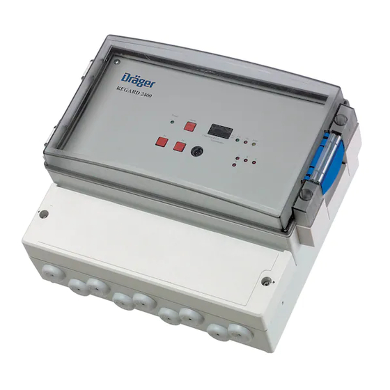
DANGER Dräger REGARD 2400 / 2410 must not be used and is not approved for use in areas where flammable and explosive gas mixtures may occur. Danger of explosion! Product Description Dräger REGARD 2400 / 2410 is a freely programmable controller unit for the connection of…
-
Page 5: Indicating And Control Elements
— One button for horn and alarm reset — Alarm memory is integrated — LEDs indicate the operating The Dräger REGARD 2400 / 2410 provides a scrolling display. The RS232 interface is for the configuration of the Dräger REGARD 2400 / 2410 via PC/Lap- top.
-
Page 6: Electrical Connections And Installation
Electrical Connections and Installation Electrical Connections and Installation DANGER Mains voltage (230 V, 50 Hz) Contact with this voltage can cause serious burns or even death. Work on electrical circuits shall only be carried out by a quallified electrician. Disconnect the mains voltage before installation! WARNING The VDE regulations, the local accident-prevention regulations and these instructions for…
-
Page 7
Electrical Connections and Installation The table shows the connection on the terminals of the Dräger REGARD 2410 / 2410. Terminal Description +24 V 24 VDC Input RS485 Interface Fault norm. closed Alarm 1 norm. closed Alarm 2 norm. closed Horn norm. -
Page 8
— All relays are freely configurable via software. Using the 24 VDC power supply input on Dräger REGARD 2400 To use the 24 VDC power supply input on the Dräger REGARD 2400 first a cable connection inside of the unit has to be changed. -
Page 9
Electrical Connections and Installation Connection diagram Dräger REGARD 2400 Mainboard INTERNAL POWER SUPPLY UNIT REGARD 2400 Mainboard 110/230 V AC 24 V DC Input Output 24 V DC Input +24 V Error Alarm 2 Alarm 1 Horn Channel Channel 19 20 21… -
Page 10
Electrical Connections and Installation The table shows the connection on the terminals of the Dräger REGARD 2400. Terminal Description with SE Ex 4…20 mA Converter Module Channel A +24 V brown signal yellow black Channel B +24 V brown signal… -
Page 11: Dräger Regard 2400 / 2410 And Catalytic Bead Sensors
Dräger REGARD 2400 / 2410 and Catalytic Bead Sensors* IMPORTANT NOTICE: If a Dräger REGARD 2400 or Dräger REGARD 2410 should be connected to a catalytic bead sensor a semi bridge converter has to be used! There are 2 different converters that could be used: SC00016 internal converter for Dräger REGARD 2400…
-
Page 12: Polytron Ec Transmitter To Dräger Regard 2410 Via A Safety Barrier
Accessories 8.2. Polytron EC* Transmitter to Dräger REGARD 2410 via a Safety Barrier Example for Connection: Ex Area Safe Area 230 VAC 24 VDC Polytron – Dräger REGARD 24xx 4…20 mA Input 4…20mA Safety Barrier e.g. Stahl 9160/13-11-11 When using Safety Barriers from other suppliers, it is recommended that you refer to the Installation and Operating manual of the specific Safety Barrier being used.
-
Page 13: Digital Inputs
8.4. RS485 Output Terminal Dräger REGARD 2400 / 2410 On the Dräger REGARD 2400 and Dräger REGARD 2410 there are 3 contacts for the com- munication with optional modules (for Dräger REGARD 2400 see connection diagram page 32, for Dräger REGARD 2410 see connection diagram page 34) like I/O module (see…
-
Page 14: I/O Module
+ D8 The I/O module (input-output module) has 6 digital inputs and 6 analog outputs. The module communicates with the Dräger REGARD 2400 / Dräger Regard 2410 via the RS485 connec- tion. To connect the module with the Dräger REGARD 24xx the terminals A / B / COM must be used.
-
Page 15: Relay Module
The module communicates with the Dräger REGARD 2400 / 2410 via the RS485 connection. To connect the module with the Dräger REGARD 2400 / 2410 the terminals A / B / COM must be used. The module needs a seperate 24 VDC supply.
-
Page 16
Relay Module Module address Switch on Relay module address This represents module one This represents module two This represents module three This represents module four IMPORTANT NOTICE: When an I/O module is installed the addressing of the relay modules must be 1 to 3 only. The configuration address in the configuration software and the relay modules must be the same. -
Page 17: The Dräger Regard 2400 / 2410 Menu
LOG: Showing the status of the datalogger. On the following 3 pages the menu-structure of the Dräger REGARD 2400 / 2410 is descri- bed. To get to the different menu point the buttons F1, F2 or F1+F2 (together) have to be used.
-
Page 18
The Dräger REGARD 2400 / 2410 Menu Menu Value F1+F2 Error INHI Inhibit Function Code Activated F1+F2 Inhibit Function Error F1+F2 MOFF Average Value Code F1+F2 Average Value OFF Error F1+F2 TOUT Sub Menu Code Relay Test F1+F2 Relay Test… -
Page 19
The Dräger REGARD 2400 / 2410 Menu Relay-Test-Menu F1+F2 current conditon de-energized energized T1 x Alarm relay 1 F1+F2 T2 x Alarm relay 2 F1+F2 THUx Horn relay F1+F2 TERx Error relay F1+F2… -
Page 20
The Dräger REGARD 2400 / 2410 Menu Configuration-Information-Menu A1Fu A2Fu R1 x A123 * Alarm function * Alarm function Function relay 1 Value threshold 1 threshold 2 F1 o. F2 A1Le A2Le R1xx A Un * value * value Time function… -
Page 21: Configuration
13. Maintenance 13.1. Inhibit The «Inhibit» function on the Dräger REGARD 2400 / 2410 locks all relays while calibrating or configuring the unit. The «Inhibit» mode will reset itself automatically after 20min. To activate «Inhibit» see Flow-Chart on page 44.
-
Page 22
The output current can be checked with a voltmeter at the two test points on the left hand side of the converter («Measuring Point 4…20mA»). Alternatively you may refer to the dis- play of the Dräger REGARD 2400, provided that the corresponding channel is configured correctly. -
Page 23: Potentiometers And Test Points At The Converter
Use the potentiometer «Adjust sensor sensitivity» to adjust the output current to the value which corresponds to the span gas being used. If a 50 %LEL reference gas is used, the display on the Dräger REGARD 2400 shall indicate «50»; the voltmeter should indicate 1.2 V (corresponding to 12 mA).
-
Page 24: Technical Data
Technical Data 14. Technical Data Dräger REGARD 2410 Supply Voltage d.c. 24 VDC ±10 % Power Consumption w/o connected Approx. 2.5 W sensors 4…20 mA Input Channels Digital Inputs Input 4…20 mA, input load 350 Ohm error at <3.5 mA error at >23 mA fault hysteresis 0.2 mA Output Relays…
-
Page 25
Technical Data Dräger REGARD 2400 Supply Voltage a.c. 110/230 VAC ±10 %, 50hz Supply Voltage d.c. 24 VDC ±10 % Power Consumption w/o connected Approx. 3 W sensors 4…20 mA Input Channels Digital Inputs Input 4…20 mA, input load 350 Ohm error at <3.5 mA… -
Page 26
Technical Data I/O Module Supply Voltage d.c. 24 VDC ±10 % Power Consumption Approx. 3 W Communication RS485 Input 6 digital inputs Output 6 analogue outputs Ambient Conditions Temperature: –20 C to 60 Relative Humidity: 10 % to 90 % r.h. Cable Terminals Screw terminals for solid wires up to 4 mm… -
Page 27: Order List
External Converter Module SE Ex 4-20 mA, 36 04 655 DIN Rail mounting, for Dräger REGARD 2410 I/O module for Dräger REGARD 2400 / 2410 SC 00 018 Relay module for Dräger REGARD 2400 / 2410 SC 00 019 Configuration Set International (Cable and Software)
-
Page 28: Zulassungen / Appovals
Zulassungen / Appovals Zulassungen / Appovals…
-
Page 29
Zulassungen / Appovals… -
Page 30
Zulassungen / Appovals… -
Page 31
Zulassungen / Appovals… -
Page 32: Konformitätserklärung / Decaration Of Conformity
Konformitätserklärung / Decaration of Conformity Konformitätserklärung / Decaration of Conformity…
-
Page 34
Dräger Safety AG & Co. KGaA Revalstraße 1 D-23560 Lübeck Germany Tel. +49 451 8 82- 0 +49 451 8 82- 20 80 www.draeger.com 90 33 025 — GA 4675.896 de_en © Dräger Safety AG & Co. KGaA 1st edition — 07_2007…
-
manualzz.com
Инструкции и Руководства для Dräger REGARD 2400.
Мы нашли 3
инструкции доступные для бесплатного скачивания:
Инструкция по эксплуатации
Dräger REGARD 2400, REGARD 2410 Instrucciones De Uso
Бренд:
Dräger
Размер:
14 MB
Страниц:
240
Язык(и):
Немецкий, Английский, Испанский, Голландский, Русский, Турецкий, zh
Открыть в новой вкладке
Dräger REGARD 2400, REGARD 2410 Instructions For Use Manual
Бренд:
Dräger
Размер:
2 MB
Страниц:
34
Язык(и):
Английский
Открыть в новой вкладке

Dräger REGARD 2400, REGARD 2410 Gebrauchsanweisung
Бренд:
Dräger
Размер:
3 MB
Страниц:
60
Язык(и):
Немецкий, Английский
Открыть в новой вкладке
Конфигурационное программное обеспечение
12.4.2
Память данных
Рис. 19
В настройках регистратора данных можно выбрать данные, которые должен записывать
регистратор.
12.5
COM-порт
В пункте меню File – COM Port (Файл – COM-порт) можно выбрать соответствующие
настройки связи между ПК и контроллером, см. раздел «Меню проверки конфигурации —
Configuration Information» на стр. 148.
12.6
Передача конфигурации в REGARD 2400/2410
Для передачи конфигурации в REGARD 2400/2410 введите пароль «1875». Появится
всплывающее окно, сообщающее, что после загрузки новой конфигурации могут
измениться настройки реле и сработать сигнал тревоги. При загрузке новой конфигурации
память данных может быть сброшена.
12.7
Специальная функция
Специальная функция доступна при выборе Function – Special function (Функция –
Специальная функция). После ввода пароля «1875» можно будет изменить состояние
блокировки, среднего значения и проверки реле.
12.8
Онлайн мониторинг
Меню Function – Monitor (Функция – Монитор) позволяет просмотреть текущие
измеренные значения и тревоги REGARD 2400/2410. Зеленый индикатор указывает на
нормальное состояние,
предупреждение о неисправности.
156
красный индикатор указывает на активацию тревоги или
02233025_en.eps
Dräger REGARD 2400/2410
Draeger REGARD 2400 и REGARD 2410
Универсальные небольшие контроллеры Draeger REGARD 2400 и REGARD 2410 в комбинации с измерительными головками надежно контролируют концентрации токсичных газов и кислорода, а также горючих газов и паров. Они могут быть установлены на стене или встроены в шкаф управления.
Преимущества
Версии и конфигурация
К контроллерам Regard 2400 и Regard 2410 можно подключить до четырех измерительных головок.
Regard 2400 представляет собой корпус настенной установки и поставляется в сборе, включая источник питания.
Экономичный вариант контроллера Regard 2410 был спроектирован для установки на DIN-рейки в существующие шкафы управления или настенные шкафы. Обе версии имеют четыре встроенных реле, отрабатывающих две тревоги по концентрации газа, звуковое предупреждение и тревогу по неисправности.
В дополнение к четырем входам для измерительных головок контроллеры Regard 2400/2410 снабжены двумя цифровыми входами, которые могут использоваться, например, для дистанционного квитирования. Оба контроллера имеют аттестацию ATEX.
Универсальность
Через внутренний интерфейс Modbus контроллеры Regard 2400 и 2410 можно соединить с внешними модулями, например, входным или выходным, а также с одним или несколькими релейными модулями.
Простота эксплуатации
Первичная настройка Regard 2400/2410 выполняется с помощью ноутбука или ПК. Соответствующий соединительный кабель и необходимое программное обеспечение заказываются отдельно как принадлежности.
Написать отзыв
Ваше Имя:
Ваш отзыв:
Внимание: HTML не поддерживается! Используйте обычный текст.
Оценка: Плохо
Хорошо
Введите код, указанный на картинке:
