Контакты
г. Москва, 1-й Нагатинский проезд, д. 2
Телефон: +7 (499) 406-00-60
PGlmcmFtZSBzcmM9Imh0dHBzOi8vd3d3Lmdvb2dsZS5jb20vbWFwcy9lbWJlZD9wYj0hMW0xOCExbTEyITFtMyExZDIyNDkuMzg3NTA2MTMwOTE2ITJkMzcuNjMwODk3MjE1NjY5MzMhM2Q1NS42ODIyNTAzODA1MzQ1MDUhMm0zITFmMCEyZjAhM2YwITNtMiExaTEwMjQhMmk3NjghNGYxMy4xITNtMyExbTIhMXMweDQxNGFiMzU2NzFjNWJhNmYlM0EweDMxZjc1Y2RiZGU0YzI4OWMhMnpNUzNRdVNEUW5kQ3cwTFBRc05HQzBMalF2ZEdCMExyUXVOQzVJTkNfMFlBdDBMUXNJRElzSU5DYzBMN1JnZEM2MExMUXNDd2dNVEUzTVRBMSE1ZTAhM20yITFzcnUhMnNydSE0djE0OTk4MjAxOTU4NjEiIHdpZHRoPSI2MDAiIGhlaWdodD0iNDUwIiBmcmFtZWJvcmRlcj0iMCIgc3R5bGU9ImJvcmRlcjowIiBhbGxvd2Z1bGxzY3JlZW4+PC9pZnJhbWU+
Спасибо. Мы свяжемся с вами как можно скорее.
-
Contents
-
Table of Contents
-
Bookmarks
Quick Links
Corrigo E — manual
Ventilation application
Related Manuals for Regin Corrigo E Series
Summary of Contents for Regin Corrigo E Series
-
Page 1
Corrigo E — manual Ventilation application… -
Page 2: Port
The software described in this document is supplied under licence by Regin and may be used or copied only in accordance with the terms of the licence. No part of this document may be reproduced or transmitted in any form, in any fashion, electronically or mechanically, without the express, written permission of Regin.
-
Page 3: Table Of Contents
Table of contents Chapter 1 About the manual More information Chapter 2 About Corrigo E Chapter 3 Installation and wiring 3.1 Installation 3.2 Wiring Chapter 4 Commissioning 4.1 How to do it Chapter 5 Functional description 5.1 Temperature control 5.2 Extra control circuit 5.3 Humidity control 5.4 Fan control 5.5 Pump control…
-
Page 4
9.4 Inputs/Outputs Chapter 10 Temperature Chapter 11 Air control Chapter 12 Humidity control Chapter 13 Time settings 13.1 Time / Date 13.2 Timer Normal speed 13.3 Timer Reduced speed 13.4 Extended running 13.5 Timer outputs 1…5 13.6 Holidays Chapter 14 Manual / Auto Chapter 15 Settings 15.1 Control temp 15.2 Control pressure… -
Page 5
16.23 Step controllers 16.24 Recirculation 16.25 Alarm setting 16.26 Communication 16.27 Other parameters 16.28 System Chapter 17 Expansion model 17.1 Port 1 17.2 Port 2 17.3 Wiring Chapter 18 Other functions 18.1 Alarm handling 18.2 Free text 18.3 Revision number 18.4 Language 18.5 Indication LEDs 18.6 Changing the battery… -
Page 6: Chapter 1 About The Manual
Chapter 1 About the manual This manual covers all the models in the Corrigo E series used with the ventilation application. This revision covers program revisions from 3.0. More information More information about Corrigo E can be found in: …
-
Page 7: Chapter 2 About Corrigo E
Chapter 2 About Corrigo E The Corrigo E series comprises three model sizes: 8, 15 or 28 in-/outputs. In each model of Corrigo E generation 2, all applications are loaded in a separate memory area. The models have article number E…-S (where S stands for Second generation). From version 3.0, there are models with two communication ports.
-
Page 8
Use the up and down arrows to move the cursor in the left edge of the display to the application you wish to load. Press right arrow to choose the selected application and go to Language choice. Ventilation Choose language English Accept changes:No Press OK to choose language. -
Page 9
Humidity control Either Humidification or Dehumidification or both Humidification and Dehumidification. Timer control For starting and stopping the unit. Up to 5 timer outputs for control of external functions such as lighting, doorlocks etc. Demand control In buildings with strongly varying occupancy the fan speeds or mixing dampers can be controlled by the air quality measured by a CO /VOC sensor. -
Page 10
Corrigo E hardware overview Model Analogue Inputs Digital Inputs Universal Inputs Analogue Outputs Digital Outputs RS485* Option Option Option Option Option Option WEB (TCP/IP) Option Option Option Option Option Option 2-port Option Option Option Option Display Ext. display Option Option Option *Communication port RS485 is not available for option WEB (TCP/IP). -
Page 11: Technical Data
Technical data Protection class ……………………IP20 Display…………4 rows of 20 characters. Background illumination. LEDs Yellow ………………….. Settable parameter Red……………………Alarm indication Clock …………..Year base 24 hour clock with battery backup. Automatic summer-/winter-time changeover. Operating system ………………….EXOreal Supply voltage …………24 V AC ±15%, 50…60 Hz or 20…36 V DC Power consumption ……..5 VA, 3 W (DC), model WEB: 9 VA, 5 W (DC) Dimensions…………..
-
Page 12
Options LON…………..FT3150, gives a second communication route WEB (TCP/IP port) ……Replaces RS485 for EXOline (Port 1) communication 2-port Corrigo models ……Two serial ports or one serial port and one TCP/IP port External hand terminal, E-DSP ……For use with Corrigo E units without display Position of the terminals on Corrigo E Manual Corrigo E Ventilation, revision M Chapter 2 About Corrigo E… -
Page 13: Chapter 3 Installation And Wiring
Chapter 3 Installation and wiring 3.1 Installation Corrigo E can be mounted in a DIN-standard casing (minimum 9 modules), on a DIN-rail in a cabinet or, using a suitable front-mounting kit, in a cabinet door or other control panel. Ambient temperature: 0…50°C. Ambient humidity: max.
-
Page 14
3.2.2 Inputs and outputs The list of input and output functions in section 3.2.3 is a handy instrument to help you keep track of which inputs and outputs you will need to configure. Analogue inputs Analogue inputs must refer to an Agnd terminal placed in the same terminal block as the input being wired. -
Page 15
24 V AC supply and 24 V AC relays 24 VAC 24 V DC supply and 24 V DC relays 24 V DC 24 V AC supply and 24 V DC relays 24 VAC Manual Corrigo E Ventilation, revision M Chapter 3 Installation and wiring… -
Page 16
24 V DC supply and 24 V AC relays 24 V DC 3.2.3 Input and output lists Use these lists during commissioning to help you keep track of which input and output functions you wish to use. Analogue inputs Analogue input signal Outdoor temperature sensor Supply air temperature sensor… -
Page 17
Digital inputs Digital input signal Filter guard, supply air and extract air Run-indication/alarm circulation pump, heating Run-indication/alarm circulation pump, cooling Run-indication/alarm circulation pump, exchanger Fire alarm Fire damper end-switch monitoring Extended running normal Extended running reduced External stop External alarm Flow guard Rotation sentinel, exchanger Run-indication/alarm supply air fan… -
Page 18
Digital outputs Digital output signal Start/stop Supply air fan Normal Start/stop Extract air fan Normal Start/stop Supply air fan Reduced Start/stop Extract air fan Reduced Start/stop circulation pump, heating Fire dampers Sum alarm A- and B-alarm Sum alarm A-alarm Sum alarm B-alarm Start/stop circulation pump, cooling Start/stop circulation pump, liquid exchanger… -
Page 19
Wiring diagram Corrigo E28-S factory configuration (See also the picture of the position of the terminals on page Supply voltage 24 V AC or 24 V DC, ±15%. 50/60 Hz RS485 EXOline / Modbus (not in WEB (TCP/IP) models) Protective earth +24 V DC.
 -
Page 20
Wiring diagram Corrigo E8-S factory configuration Supply voltage 24 V AC or 24 V DC, ±15%. 50/60 Hz RS485 EXOline / Modbus (not in WEB (TCP/IP) models) Protective earth +24 V DC. Reference for digital inputs DI. Reference for digital outputs DO. Net+ Start/stop supply air fan (SAF) 1/1-speed Net-… -
Page 21
Empty wiring diagram Corrigo E15-S Supply voltage 24 V AC or 24 V DC, ±15%. 50/60 Hz RS485 EXOline / Modbus (not in WEB (TCP/IP) models) Protective earth +24 V DC. Reference for digital inputs DI. Reference for digital outputs DO. Net+ Net- LON-connection (LON-versions only) -
Page 22
Empty wiring diagram Corrigo E282-S Supply voltage 24 V AC or 24 V DC, ±15%. 50/60 Hz RS485 EXOline / Modbus (Port 1) Protective earth +24 V DC. Reference for digital inputs DI. Reference for digital outputs DO. RS485 EXOline / Modbus (Port 2) Agnd Reference pole for analogue inputs AI Agnd… -
Page 23: Chapter 4 Commissioning
The best way however, is to configure the Corrigo E by using Corrigo E tool. Corrigo E tool is a PC-based configuration program specially developed to simplify the commissioning of the Corrigo E series. When using E tool the whole configuration and all settings can be done on the computer and then be downloaded to the Corrigo.
-
Page 24
Option 2: Read this manual in the order given below: The manual has been designed to act as a guide through the commissioning. The last chapters of the manual, not listed below, cover menus and functions that are not used during commissioning. Functional description Start by reading chapter 5. -
Page 25
Other functions Chapter 18 Alarm handling etc. Manual Corrigo E Ventilation, revision M Chapter 4 Commissioning… -
Page 26: Chapter 5 Functional Description
Chapter 5 Functional description 5.1 Temperature control General Corrigo E has a choice of the following control modes: 1. Supply air control 2. Outdoor temperature compensated supply air control 3. Cascaded room temperature control 4. Cascaded extract air temperature control 5.
-
Page 27
0% Heating at HCOut = 54% 100% Heating at HCOut = 100% Output signal 100% Cooling Heat Heating Controller exch. signal 100% Heat demand In addition to these three, it is possible to connect another anologue output signal for control of an optional sequence, Y4 Extra sequence. -
Page 28
3. Cascaded room temperature control. Cascade control of room temperature and supply air temperature to achieve a constant, settable room temperature. The room controller output signal generates the supply air controller’s setpoint value. One or two room sensors can be connected. If two sensors are connected the average of their values will be used. -
Page 29
Inputs and outputs 6 Control modes AI AI AI AI AI AI Supply air sensor AI AI Outdoor temperature sensor Room temperature sensor(s) AI Exhaust air sensor AO AO AO AO AO AO Y1 Heating 0…10 V DC ** AO AO AO AO AO AO Y2 Exchanger 0…10 V DC ** AO AO AO AO AO AO Y3 Cooling 0…10 V DC ** AO AO AO AO AO AO Y4 Extra sequence 0…10 V DC Extra split Y1, Y2 or Y3 0…10 V… -
Page 30
“Internal signal” Prop.band 100 % “Frost protection sensor” Alarm level Shutdown mode If frost protection is activated the controller will go into ”Shutdown mode” when the running mode switches to ”Off”. The shutdown controller will control the heating output to maintain a constant settable temperature at the frost protection sensor. -
Page 31
5.1.2.4 Fast stop on overheating If this function is active, the fans will be immediately stopped when there is an overheating alarm, regardless of the set cool-down time. Inputs and outputs Water Electric heating heating Frost protection sensor (optional) Frost protection thermostat DI** (optional) High temp. -
Page 32
Rotating exchanger Control Rotational speed is controlled by the analogue signal ”Y2 Heat exchanger” or by two digital outputs “Exchanger 3-pos. actuator, increase” and “Exchanger, 3-pos. actuator, decrease”. A rotation sentinel can be connected to the digital input ”Rotation sentinel Exchanger”. An alarm is generated if this input is activated at the same time as the analogue output signal is higher than 1.0V. -
Page 33
Inputs and outputs Plate Rotating Liquid Dampers Outdoor temp sensor (optional, outd. temp start) Activation exchanger (optional, outd. temp start) De-icing sensor (optional) De-icing signal (optional) Rotation sentinel, exchanger (optional) 5.1.4 Step controller Heating/ DX cooling As alternative or complement to the above mentioned analogue control, heating and cooling can be activated in steps. -
Page 34
DX cooling with room or extract air control If DX cooling is used in conjunction with room temperature control or extract air temperature control, there are two configuration alternatives, DX cooling or DX cooling with exchanger control. DX cooling without exchanger control When running cascade control, the supply air controller setpoint is normally controlled by the room/extract air controller output signal. -
Page 35
Blocking of DX cooling on cooling pump alarm Corrigo can be configured to block DX cooling on cooling pump alarm. Inputs and outputs Heating Cooling Heating/ Cooling Change- over Step controller, step 1 (optional) Step controller, step 2 (optional) Step controller, step 3 (optional) Step controller, step 4 (optional) 5.1.5 Support control Support control is normally used when room temperature control or extract air control has been… -
Page 36
5.1.6 Free cooling This function is used during the summer to cool the building night-time using cool outdoor air, thereby reducing the need for cooling during the day and saving energy. Free cooling requires an outdoor sensor and either a room sensor or an extract air sensor. The outdoor sensor can be placed in the fresh air inlet duct. -
Page 37
5.1.7 Cooling recovery If the extract air temperature is a settable amount lower than the outdoor temperature, cooling recovery can be activated. When cooling recovery is activated the heat exchanger signal will be reversed to give increasing recovery on increasing cooling demand. Output signals 100% Controller signal… -
Page 38
Alarms An alarm is activated if the efficiency falls below the set alarm level (50%). Inputs and outputs Outdoor temperature sensor Exhaust air sensor Extract air temperature sensor 5.1.10 External setpoint An external setpoint device, for example TBI-PT1000 or TG-R4/PT1000 can be connected. The setpoint device must follow the PT1000 resistance curve. -
Page 39: Extra Control Circuit
A special analogue output signal, Y1 Heating/Y3 Cooling, is used for Change-over control. Switching between heating and cooling can be done in two ways. A digital Change-over input signal is normally used. Open contact will give heating control and closed contact cooling control. If the input has not been configured, change-over is handled by the internal controller signal.
-
Page 40: Fan Control
Digital humidity signal A digital output signal, Dehumidification/Humidification, can be used for on/off control of humidifier/dehumidifier. The output signal has an activation value and a deactivation value which are connected to the humidity controller output. The signal is activated when the humidity controller output rises above the set activation value and is deactivated when the humidity controller output drops below the set deactivation value.
-
Page 41
5.4.1 Pressure control Frequency control pressure When running pressure control, two analogue output signals are used for supply and extract air respectively. The signals control the fan speeds via frequency converters, thereby maintaining constant pressure. A digital activation signal is normally used for each fan (Start SAF frequency converter and Start EAF frequency converter), for sending a start signal to the frequency converters. -
Page 42
Frequency control external control signal Two 0…10 V input signals are used for direct control of frequency controlled fans. The signal is received from for example a VAV unit. The signal controls the fans 0…100% (0…10V on the analogue output). Pressure transmitters are not used in this control mode. Frequency control SAF with EAF slave The rotational speed of the supply air fan is controlled by a pressure transmitter which is placed in the supply air duct. -
Page 43
You can choose to activate the function 1. Always, 2. Only when the running mode is On, 3. Only when the running mode is Off. When the function is activated and combined with pressure controlled fans and the CO /VOC-value rises above control value 1 the fans will start at low speed, if they are not already running. -
Page 44: Pump Control
If demand controlled ventilation is activated in combination with mixing dampers, and the CO value rises above the setpoint value, the dampers will let in more fresh air. The function is controlled by a PI-controller. See section 5.1.3 Heat exchanger types. The function has a settable minimum running time.
-
Page 45: Damper Control
5.6 Damper control 5.6.1 Close-off dampers The fresh air and exhaust air ducts close-off dampers can be controlled by digital outputs or be hard- wired to the supply air fan relays for normal and reduced speed in such a fashion that the damper is open when the supply air fan is running.
-
Page 46: Extended Running And External Stop
The fire alarm input can be configured as normally closed or normally open. Inputs and outputs Fresh air damper control Exhaust air damper control Fire dampers Fire alarm Fire damper end switch monitoring 5.7 Extended running and External stop The digital inputs for extended running can be used to force the unit to start although the timer says the running mode should be “Off”.
-
Page 47: Alarms
5.9 Alarms Alarm handling Alarms are indicated by the red alarm LED on the front or on E-DSP. All alarms can be monitored, acknowledged and blocked using the display and buttons. Alarm priorities Alarms can be given different priority levels, A-alarm, B-alarm, C-alarm or not active. Digital outputs can be bound to act as alarm outputs for A-alarms or B-alarms or both A- and B alarms.
-
Page 48: Chapter 6 Starting And Stopping The Unit
Chapter 6 Starting and stopping the unit 6.1 Start conditions The unit will be started and will run when any one of the following conditions is met: 1. Timer output for normal speed or timer output for reduced speed is ON (normal running) 2.
-
Page 49: Stop Sequence
4. The supply air fan or the control of the supply air pressure will be started after a preset time. 5. The extract air fan or the control of the extract air pressure will be started after a preset time. 6.
-
Page 50: Chapter 7 Display, Leds And Buttons
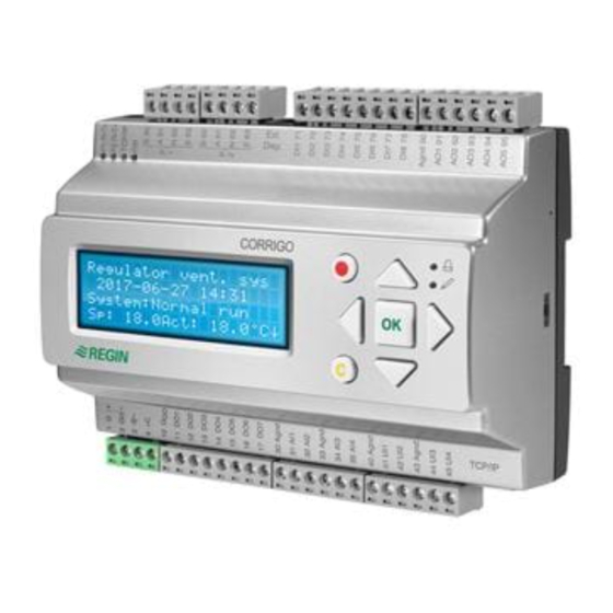
Chapter 7 Display, LEDs and buttons This section is applicable to Corrigo E units with display and buttons but also to the hand terminal E-DSP which can be connected to Corrigo E units without display and buttons. 7.1 Display The display has 4 rows of 20 characters. It has background illumination.
-
Page 51: Navigating The Menus
7.4 Navigating the menus From revision 2.3, significant changes have been made to the Corrigo menu system. The purpose is to make the menu system more structured and user-friendly. The choice of access level/user access determines which menus are shown. The start display, the display normally shown, is at the root of the menu tree.
-
Page 52
If there are further settable values displayed the cursor will automatically move to the next one. To pass a value without changing it, press RIGHT. To abort a change and return to the initial setting, press and hold the C-button until the cursor disappears. -
Page 53: Chapter 8 Access Rights
Chapter 8 Access rights There are four different access levels, System level which has the highest access, Service level, Operator level and the basic “no-log on” level. The choice of access level determines which menus are shown, as well as which parameters can be changed in the displayed menus. System level gives full read / write access to all settings and parameters in all menus.
-
Page 54: Change Password
Forgotten your password? If the password for System has been changed and then lost, a temporary password can be obtained from Regin. This code is date dependent and only valid for one day. 8.4 Change password to remove automatic logoff If you want to remove the automatic logoff, change the password of the desired level to 0000.
-
Page 55: Chapter 9 Running Mode
Chapter 9 Running mode Collected here are a number of menus showing running mode, selected functions, alarm events and status of inputs and outputs. Running mode Selected functions Alarm events Input/Output 9.1 Running mode The unit’s running mode can be changed without logging on. Running mode Auto Running time…
-
Page 56: Alarm Events
Frost protection Active Cooling recovery External setpoint Not active 9.3 Alarm events Alarm log which contains the 40 latest alarm events. The most recent event is listed first. The alarm log can only be used for viewing the alarm history. Alarms are handled in a special area, see section 18.1.
-
Page 57: Chapter 10 Temperature
Chapter 10 Temperature Here you can view all actual and setpoint values for temperature control. The menu is visible to all users, regardless of log on level. However, to make changes you need at least Operator authority. The following menus are available providing that the corresponding input is activated: Setpoint.
-
Page 58
In control mode 5, the setpoint is used when cascaded room control is active. Submenu for setting the min and max limitation temperatures for the supply air. If cascade control max/min supply setp. Max: 30.0°C Min: 12.0°C If two room sensors have been configured you will also get the following menu: Room temp.2 Actual: 21.8°C Setpoint. -
Page 59
Recirculation See 5.1.11 Temp.setpoint when recirc. (Supply/ Extract/Room) 18.0°C Offset SAF when frequency control and recirculation: 0.0 Pa Offset SAF makes it possible to add an offset to the setpoint during normal operation. If pressure control has been configured, the offset is set in Pa. If flow control has been configured, it is set in m3/h. -
Page 60: Chapter 11 Air Control
Chapter 11 Air control Pressure control SAF and EAF When using pressure or flow controlled fans, the setpoint can be outdoor compensated. The compensation has the default value 0 Pa, i.e. no compensation is added. The compensation is linear between the setting points. The compensation can be positive or negative. The same compensation normally applies to both fans.
-
Page 61
Submenu Setpoint Frequency control manual SAF Output 1/1: 75% Output 1/2: 50% Submenu Outdoor compensation Outdoor comp. outp. -20 °C = 0 % 10 °C = 0 % Act. comp: 0 % CO2 / VCO Actual:920ppm Setp:850pm Manual Corrigo E Ventilation, revision M Chapter 11 Air control… -
Page 62: Chapter 12 Humidity Control
Chapter 12 Humidity control Humidity control can be configured as Humidification, Dehumidification or both Humidification and Dehumidification. Two humidity sensors can be connected, a room sensor for control and an optional duct sensor for maximum limiting. The limit sensor can be omitted. The humidity control is handled by a PI-controller.
-
Page 63: Chapter 13 Time Settings
Chapter 13 Time settings General Corrigo has a year-base clock function. This means that a week-schedule with holiday periods for a full year can be set. The clock has an automatic summer- winter-time changeover. Individual schedules for each week-day plus a separate holiday setting. Up to 24 individual holiday periods can be configured.
-
Page 64: Timer Reduced Speed
If you want to run the unit from one day to another, e. g. from Mon 22:00 to Tue 09:00, the desired running time for both days must be entered. Normal speed Monday Per 1: 07:00 – 16:00 Per.2: 22:00 — 24:00 Normal speed Tuesday Per 1: 00:00 –…
-
Page 65: Holidays
13.6 Holidays Up to 24 separate holiday periods for a full year can be set. A holiday period can be any number of consecutive days from one and upwards. The dates are in the format: MM:DD. When the current date falls within a holiday period, the scheduler will use the settings for the weekday “Holiday”.
-
Page 66: Chapter 14 Manual / Auto
Chapter 14 Manual / Auto General In this menu the running mode of all the configured output signals and a number of control functions can be manually controlled. This is a very handy feature which simplifies the checking of individual functions in the Corrigo. The running mode for the whole unit is set in the menu Running mode.
-
Page 67
Y1 heating output Heating Auto Manual set: 0.0 Y2 heat exchanger Exchanger Auto Manual set: 0.0 Y3 cooling Cooling Auto Manual set: 0.0 Humidification/dehumidification Humidification/Dehumidi fication Auto Manual set: 0% Circulation pumps: Heating, Exchanger and Cooling P1-Heating Auto P1-Exchanger Auto Dampers: Fresh air, Recirculation air, Exhaust air and Fire dampers Fresh air damper Auto… -
Page 68: Chapter 15 Settings
Chapter 15 Settings In this menu group all settings for all activated functions should be available. The menu group is only available when logging on as System. Depending on what choices have been made during configuration, some of the alternatives in this menu group may not be shown. Settings Control temp Control pressure…
-
Page 69: Control Pressure
Shutdown mode Shutdown mode P-band: 100.0 °C I-time: 100 sec Frost protection temperature Frost protection temperature -> Frost protection Active Setp shutdown: 25°C P-band active: 5°C Fast stop at frost-protection alarm Setp shutdown is the shutdown mode setpoint. P-band active 5°C means that the frost protection controller will start overriding the heating output when the frost protection temperature is less than 5 degrees above the set frost alarm limit.
-
Page 70: Humidity Control
Flow control EAF Flow control EAF P-band: 1000 m3/h I-time: 60 sec Min Output: 0 % 15.4 Humidity control Control humidity P-band: 100.0 %RH I-time: 300.0 sec 15.5 Control Extra unit Control extra unit P-band: 33.0 °C I-time: 100.0 sec 15.6 Alarm settings Alarm settings …
-
Page 71
Alarm limit, pressure Control dev SAF 40.0 Pa Control dev EAF 40.0 Pa Alarm limit Humidity Control deviation humidity 10 % Alarm limit, exchanger efficiency Low efficiency 50.0 % Service alarm filter Service alarm (Filter alarm) Time until alarm Activates: 0 month 15.6.2 Alarm delays Alarm delay, supply air Al. -
Page 72: Save And Restore Settings
Alarm delay, exchanger efficiency Low efficiency 30 min Alarm delay, fan malfunction Alarm delay malfunc. SAF: 120 sec EAF: 120 sec Alarm delay, pump malfunction Alarm delay malfunc. P1-Heating: 5 sec P1-Cooling: 5 sec P1-Exchan.: 20 sec Alarm delay, misc. Alarm delay Filter mon.: 180 sec…
-
Page 73: Chapter 16 Configuration
Chapter 16 Configuration Start by logging on at System level. See chapter 8. Move the marker using the DOWN and UP buttons until it is opposite the menu Configuration and press RIGHT. The configuration main menu is shown (different menus are visible depending on the configured inputs and outputs).
-
Page 74
16.1.1 Analogue inputs AI Sign: Outdoor temp Raw value: 18,4 Compensation:0,0 All analogue inputs are for PT1000 or 0-10 Volts. Input signals can be compensated for example for wiring resistance. The Raw value will show the actual uncompensated input value. If inputs have been assigned to pressure or flow control of fans, alternatively humidity or CO control, the following menus will appear: SAF Pressure at… -
Page 75: Control Function
Universal AI1 Sign: SAF pressure Raw Value:8.5 Compensation: 0.0 Universal DI1 NO/NC: NO Signal Not used Status: Off To simplify adaptation to external functions, all universal inputs configured as digital inputs can be set to be either normally open, NO, or normally closed, NC. The inputs are as standard normally open, i.
-
Page 76: Fan Control
Outdoor temp for control mode change 13°C 16.3 Fan control Fan control 1-speed Choose between Single-speed, Two-speed, Pressure control, Flow control, Frequency manual (fixed output), Frequency external control, SAF with EAF slave, or SAF with EAF flow control. For detailed description of fan control alternatives, see section 5.4 Fan control. Flow control If flow control has been configured, there is a submenu for setting of calculation parameters for conversion of pressure to flow.
-
Page 77: Extra Control Circuit
For more detailed description, see the section SAF with EAF flow control under 5.4.1 Pressure control. Crosswise interlock between fans Crosswise interlock means that if one of the fans stops running, the other fan will automatically stop as well. Crosswise interlock between SAF and EAF 16.4 Extra control circuit The extra control circuit can be configured to be either constantly active or to be active only when…
-
Page 78: Chiller
Rotating exchanger Liquid connected exchanger Mixing dampers Not connected Damper limiting for minimum fresh air percentage is settable 0…100%. In the submenu parameters for outdoor temperature control of exchanger can be set. Outd. temp control of exch: Outd.
-
Page 79: Pump Control
Block DX-cooling on alarm ”Run error P1- cooler”:No 16.9 Pump control P1-Heating P1-Exchanger P1-Cooling In these menus the parameters for pump control are set. If, for any of the control circuits, no output is configured for pump control these settings will be ignored.
-
Page 80: Support Control
Fan output when free cooling SAF: EAF: Outdoor sensor placed in intake channel For detailed description, see section 5.1.6 Free cooling. 16.11 Support control Note: If support control without EAF (extract air fan) is selected, a recirculation damper must be used.
-
Page 81: Humidity Control
Fire damper function Not active Operation when alarm Stopped Select if fire alarm should be normally closed or normally open and activation of fire damper exercising if the unit should be stopped or not: No, Yes unit running—>, Yes unit stopped—>, —>, Fire alarm input Normally open Damper exercise…
-
Page 82: Minimum Limit Dampers
16.17 Minimum limit dampers Min limit dampers Active No Min limit.: 5% For detailed description of exchanger alternatives, see section 5.1.3 Heat exchanger. 16.18 Enthalpy control Cooling recovery run when enthalpy is greater outdoor than indoor : Active For a more detailed description, see section 5.1.8 Enthalpy control. 16.19 External setpoint An external setpoint device, for example TBI-PT1000 or TG-R4/PT1000 can be connected.
-
Page 83: Actuator Type
Min pressure for run indication SAF: 25.0 Pa EAF: 25.0 Pa Alarm from frequency converter When running frequency controlled fans, you sometimes want to use both a pressure signal from a pressure transmitter and a digital alarm signal from a frequency converter. An analogue input for a pressure transmitter and a digital input for SAF or EAF indication must then be configured.
-
Page 84: Step Controllers
16.23 Step controllers Step contr. heating Step contr. Cooling 16.23.1 Step controller heating Step controller Heating can be set to sequential or binary. Step contr. heating Sequential Step controller Heating activation levels for sequential control. For binary control the activation levels are calculated by the controller depending on the number of steps involved Start step 1: 10 Stop step 1:…
-
Page 85: Recirculation
Chiller groups: 3 Minimum on/off- time: 60 sec Hyst: 0.5 % When DX cooling is used in conjunction with pressure controlled or flow controlled fans it is possible to block DX cooling if the supply air fan control signal falls below a preset values.
-
Page 86: Alarm Setting
16.25 Alarm setting Permits configuration of all alarms. Select the appropriate alarm number (from the alarm list). The alarm text for the alarm will be displayed and the alarm priority can be set: A-alarm, B-alarm, C-alarm, D-alarm or not active. The extra stop function gives, for each alarm, the option to stop or not stop the unit on alarm activation.
-
Page 87
Alarm text Pri Description 26 Low efficiency Heat exchanger efficiency below limit value 27 Sensor error Outdoor Malfunction of connected sensor temp 28 Analogue deicing Exchanger de-icing activated by de-icing sensor 29 Rotation guard Exchanger rotation sentinel alarm activated exchanger 30 Fire damper is out of Fire damper exercise test failed operation… -
Page 88
Alarm text Pri Description 56 Sensor error EAF Malfunction of connected sensor pressure 57 Sensor error Deicing Malfunction of connected sensor temp 58 Sensor error Frost Malfunction of connected sensor Protection temp 59 Sensor error CO Malfunction of connected sensor 60 Sensor error Humidity Malfunction of connected sensor Room… -
Page 89: Communication
16.26 Communication 16.26.1 Modbus communication Corrigo E can be connected to a network for Modbus communication. You do not need an activation code. Modbus slave com- munication, Port 1 Not Active If Modbus communication is activated, you can set the address etc. Modbus Address: 1 Speed: 9600 bps Two stop bits:Yes…
-
Page 90: Other Parameters
Expansion unit In order to connect more I/Os to the Corrigo, port two is set as expansion unit (only Corrigo E controllers can be connected). It is possible to connect two units which gives a maximum of 28*3 = 84 inputs/outputs. The expansion controllers must have the addresses 241:1 and 241:2 respectively (ELA:PLA).
-
Page 91
Delay EAF Start: 0 sec Stop: 30 sec 16.27.2 Retardation time When switching two-speed fans from 1/1-speed to 1/2-speed there is a settable retardation time. The same time applies to both fans. Retardation time 1/1-1/2speed: 10 sec 16.27.3 Heating at start-up and high speed blocking At outdoor temperatures below the set value, the heating output will be forced to 100% before start- Two speed fans and pressure controlled fans can be blocked from using high speed at outdoor temperatures lower than the set value. -
Page 92
For example P-band for the supply air controller is set to 33K. The HCOut is set so that cooling gets 0…30% = 30%, the exchanger gets 32…50% = 18% and the heater gets 54…100% = 46%. The individual P- bands will then be: Chiller: 30% of 33°C = 10°C Exchanger: 18% of 33°C = 6°C Heating: 46% of 33°C = 15°C… -
Page 93: System
Outdoor temp for control mode change 13.0°C 16.27.8 Split of optional temp. sequence Any one of the analogue temperature control output sequences Y1, Y2 and Y3 can be split, for example to control two heating valves in sequence. The split is always even 50/50 which means that each part of the split will have half the part of the P-band assigned to the output.
-
Page 94
Vent unit 18 PX 2004-08-15 11:28 System: Running Sp:22.0°C Act:21.8°C Type 2 The first line shows date and time. The second line shows the present running status. The third line shows the present temperature setpoint and actual values. The fourth line shows present temperature control output values. 2004-08-15 11:28 System: Running Sp:22.0°C Act:21.8°C… -
Page 95
16.28.4 Address Corrigo E uses the addresses below when connecting to Corrigo E tool, and when multiple controllers are connected in an EXO network. E tool normally uses the addresses below, so if an address is changed, the new address must also be entered in E tool. If several Corrigo are connected in a network, all the units must have the same ELA address, but each unit must have a unique PLA address. -
Page 96: Chapter 17 Expansion Model
Chapter 17 Expansion model There are eight different 2-port Corrigo models with 15/28 inputs/outputs, with or without display, and with or without TCP/IP port. For a list of the different models, see page 8 (Corrigo E model overview). 17.1 Port 1 On a 2-port Corrigo, port 1 is used for connection to E tool and possibly a SCADA system.
-
Page 97
17.3.3 Expansion controllers LON For a 2-port Corrigo to be able to communicate via LON, the first expansion controller must have a LON port. Communication between the master and expansion controllers takes place via EXOline. Manual Corrigo E Ventilation, revision M Chapter 17 Expansion model… -
Page 98: Chapter 18 Other Functions
Chapter 18 Other functions 18.1 Alarm handling If an alarm condition occurs, the red Alarm LED on the front panel of units with display or the Alarm LED on a connected display unit will start flashing. The LED will continue to flash as long as there are unacknowledged alarms.
-
Page 99: Indication Leds
The different language files are stored in the application memory and are downloaded to the work memory. If a Corrigo via E tool has been reloaded with a newer program revision than the factory revision, the controller will not allow language files to be downloaded from the application memory.
-
Page 100: Start-Up Wizard
Battery location Grip the battery firmly with your fingers and lift it upwards until it rises from its holder. Press the new battery firmly down into place. Note that to preserve correct polarity, the battery can only be inserted the “right way round”. 18.7 Start-up wizard The start-up wizard is a function that can be activated in Configuration/System.
-
Page 101
Choose language English In the second menu, the setpoint is set. The appearance of the menu depends on which control type has been configured. Supply air temp Setp.: 18°C In the third menu, time and date are set. Time: 14:27 Date: 2008-11-25 Weekday: Tuesday In the fourth menu, the running time for normal speed Monday –… -
Page 102: Chapter 19 Index
Chapter 19 Index Heat exchangers, 78 Heater type, 78 Humidity control, 82 Inputs and outputs, 74 Objects, 77 Access rights, 54 Other parameters, 92 Actuator type, 85 Pump control, 80 Address, 98 Run indication / Motor protection, 84 Air control, 61 Running time, 3-pos.
-
Page 103
Extra sequence Y4, 78 Language, change, 96, 102 LEDs, 51, 102 Liquid connected exchanger, 32 Log off, 54 Fans Log on, 54 Control, 40 Logoff, 98 Delays, 92 Frequency control external control signal, 42 Frequency control flow, 41 Frequency control SAF with EAF slave, 42 Frequency control SAF with flow control EAF, 42 Interlock, 78 Manual / Auto, 67… -
Page 104
Running time, 3-pos. actuators, 85 Temperature, 58 Temperature control, 26 Settings, 69 Time settings, 64 Save and restore settings, 73 Time/Date, 64 Selected functions, 56 Timer output ½ speed, 65 Setpoint fan control, 61 Timer output 1/1 speed, 64 Setpoint humidity control, 63 Timer outputs, 65 Setpoint, external, 38, 84 Time-switch outputs, 47… -
Page 105
Germany France Spain Singapore Hong Kong Regin Controls RICCIUS + SOHN GmbH Regin Controls SARL Regin Ibérica, S.A. Regin Controls Asia Pacific Pte Ltd Hong Kong Ltd Haynauer Str. 49 32 rue Delizy C/Arganda 18 local 66 Tannery Lane…
 Supply voltage 24 V AC or 24 V DC, ±15%. 50/60 Hz RS485 EXOline / Modbus (not in WEB (TCP/IP) models) Protective earth +24 V DC.
 | 1 | G | Напряжение питания 24 В переменного тока, ±15%. 50…60 Гц |
| 2 | GO | Нейтраль 24 В переменного тока |
| 3 | Заземление | |
| 4 | +C | +24 В постоянного тока. Общий для цифровых входов DI. |
| 10 | G | Общий для цифровых выходов DO. |
| 11 | DO1 | Пуск/остановка приточного вентилятора, нормальная скорость |
| 12 | DO2 | Пуск/остановка вытяжного вентилятора нормальная скорость |
| 13 | DO3 | Пуск/остановка циркуляционного насоса, нагрев |
| 14 | DO4 | Общая аварийная сигнализация A + В |
| 30 | Agnd | Общая нейтраль для аналоговых входов AI1-AI2 |
| 31 | AI1 | Датчик наружной температуры |
| 32 | AI2 | Датчик температуры приточного воздуха |
| 33 | Agnd | Общая нейтраль для аналоговых входов AI3-AI4 |
| 34 | AI3 | Датчик защиты от замораживания |
| 35 | AI4 | Датчик комнатной температуры 1 |
| 50 | В | Подключение RS485 EXO-line |
| 51 | A | |
| 52 | N | |
| 53 | E | |
| 57 | Net+ | Подключение LON(для версий с шиной LON) |
| 58 | Net- | |
| 59 | Egnd | |
| 71 | DI1 | Индикатор состояния /защита двигателя приточного вентилятора |
| 72 | DI2 | Индикатор состояния / защита двигателя вытяжного вентилятора |
| 73 | DI3 | Индикатор состояния /аварии циркуляционного насоса, нагрев |
| 74 | DI4 | Кнопка или таймер для продолжительного режима работы (на одной скорости) / Продолжительное время работы на высокой скорости для систем с двухскоростным вентилятором |
| 90 | Agnd | Общая нейтраль для аналоговых выходов AO |
| 91 | AO1 | Y1 нагрев |
| 92 | AO2 | Y2 рекуперация |
| 93 | AO3 | Y3 охлаждение |
Схема подключений Corrigo E8V, конфигурация завода-изготовителя
| 1 | G | Напряжение питания 24 В переменного тока, ±15%. 50…60 Гц |
| 2 | GO | Нейтраль 24 В переменного тока |
| 3 | Заземление | |
| 4 | +C | +24 В постоянного тока. Общий для цифровых входов DI. |
| 10 | G | Общий для цифровых выходов DO. |
| 11 | DO1 | Пуск/остановка приточного вентилятора, нормальная скорость |
| 12 | DO2 | Пуск/остановка циркуляционного насоса, нагрев |
| 30 | Agnd | Общая нейтраль для аналоговых входов AI1-AI2 |
| 31 | AI1 | Датчик наружной температуры |
| 32 | AI2 | Датчик температуры приточного воздуха |
| 50 | В | Подключение RS485 EXO-line |
| 51 | A | |
| 52 | N | |
| 53 | E | |
| 57 | Net+ | Подключение LON(для версий с шиной LON) |
| 58 | Net- | |
| 59 | Egnd | |
| 71 | DI1 | Индикатор состояния /защита двигателя приточного вентилятора |
| 72 | DI2 | Индикатор состояния /аварии циркуляционного насоса, нагрев нагревания |
| 73 | DI3 | Термостат защиты ТЭНов от перегрева/термостат защиты от замерзания |
| 90 | Agnd | Общая нейтраль для аналогового выхода AO1 |
| 91 | AO1 | Y1 нагрев |
Схема подключений Corrigo E28 (без учета конфигурации)
| 1 | G | Напряжение питания 24 В переменного тока, ±15%. 50…60 Гц Hz |
| 2 | GO | Нейтраль 24 В переменного тока |
| 3 | Заземление | |
| 4 | +C | +24 В постоянного тока. Общий для цифровых входов DI. |
| 10 | G | Общий для цифровых выходов DO. |
| 11 | PO1 | |
| 12 | DO2 | |
| 13 | DO3 | |
| 14 | DO4 | |
| 15 | DO5 | |
| 16 | DO6 | |
| 17 | DO7 | |
| 30 | Agnd | Общая нейтраль для аналоговых входов AI1-AI2 |
| 31 | AI1 | |
| 32 | AI2 | |
| 33 | Agnd | Общая нейтраль для аналоговых входов AI3-AI4 |
| 34 | AI3 | |
| 35 | AI4 | |
| 40 | Agnd | Общая нейтраль для универсальных входов UI1-UI2 |
| 41 | UI1 | |
| 42 | UI2 | |
| 43 | Agnd | Общая нейтраль для универсальных входов UI3-UI4 |
| 44 | UI3 | |
| 45 | UI4 | |
| 50 | В | Подключение RS485 EXO-line |
| 51 | A | |
| 52 | N | |
| 53 | E | |
| 57 | Net+ | Подключение LON(для версий с шиной LON) |
| 58 | Net- | |
| 59 | Egnd | |
| 71 | DI1 | |
| 72 | DI2 | |
| 73 | DI3 | |
| 74 | DI4 | |
| 75 | DI5 | |
| 76 | DI6 | |
| 77 | DI7 | |
| 78 | DI8 | |
| 90 | Agnd | Общая нейтраль для аналоговых выходов AO |
| 91 | AO1 | |
| 92 | AO2 | |
| 93 | AO3 | |
| 94 | AO4 | |
| 95 | AO5 |
Cхема подключений Corrigo E15V (без учета конфигурации)
| 1 | G | Напряжение питания 24 В переменного тока, ±15%. 50…60 Гц |
| 2 | GO | Нейтраль 24 В переменного тока |
| 3 | Заземление | |
| 4 | +C | +24 В постоянного тока. Общий для цифровых входов DI. |
| 10 | G | Общий для цифровых выходов DO. |
| 11 | DO1 | |
| 12 | DO2 | |
| 13 | DO3 | |
| 14 | DO4 | |
| 30 | Agnd | Общая нейтраль для аналоговых входов AI1-AI2 |
| 31 | AH | |
| 32 | AI2 | |
| 33 | Agnd | Общая нейтраль для аналоговых входов AI3-AI4 |
| 34 | AI3 | |
| 35 | AI4 |
| 50 | В | Подключение RS485 EXO-line |
| 51 | A | |
| 52 | N | |
| 53 | E | |
| 57 | Net* | Подключение LON(для версий с шиной LON) |
| 58 | Net- | |
| 59 | Egnd | |
| 71 | DI1 | |
| 72 | DI2 | |
| 73 | DI3 | |
| 74 | DI4 | |
| 90 | Agnd | Общая нейтраль для аналоговых выходов AO |
| 91 | AO1 | |
| 92 | AO2 | |
| 93 | AO3 |
Cхема подключений Corrigo E8V (без учета конфигурации)
| 1 | G | Напряжение питания 24 В переменного тока, ±15%. 50…60 Гц |
| 2 | GO | Нейтраль 24 В переменного тока |
| 3 | Заземление | |
| 4 | +C | +24 В постоянного тока. Общий для цифровых входов DI. |
| 10 | G | Общий для цифровых выходов DO. |
| 11 | DO1 | |
| 12 | DO2 | |
| 30 | Agnd | Общая нейтраль для аналоговых входов AI1-AI2 |
| 31 | AI1 | |
| 32 | AI2 | |
| 50 | В | Подключение RS485 EXO-line |
| 51 | A | |
| 52 | N | |
| 53 | E | |
| 57 | Net+ | Подключение LON(для версий с шиной LON) |
| 58 | Net- | |
| 59 | Egnd | |
| 71 | DI1 | |
| 72 | DI2 | |
| 73 | DI3 | |
| 90 | Agnd | Общая нейтраль для аналогового выхода AO1 |
| 91 | AO1 |
3. Подготовка к эксплуатации
Общая характеристика:
Перед введением Corrigo E в эксплуатацию, необходимо сконфигурировать входы и выходы, а также все необходимые параметры.
Процесс конфигурации осуществляется через переднюю панель Corrigo или при помощи дисплейного блока E-DSP.
Сервисная программа Corrigo E-Tool.
Проще всего cконфигурировать Corrigo E с помощью Corrigo E Tool. Это компьютерная сервисная программа, специально разработанная для упрощения процесса конфигурации контроллеров серии Corrigo E. С Corrigo E Tool конфигурация полностью выполняется на компьютере и затем загружается в контроллер Corrigo. Файл конфигурации можно сохранить для дальнейшего использования.
3.1 Как сконфигурировать контроллер:
Для конфигурации с помощью E Tool обращайтесь к инструкции E Tool.
Конфигурацию через переднюю панель прибора можно осуществлять двумя путями в зависимости от Вашей степени квалификации.
Вариант 1:
- Сразу перейдите к главам 6 и 7 «Дисплей, кнопки управления и индикаторы» и «Права доступа к системе».
- После ознакомления с кнопками управления и меню подайте напряжения питания к Corrigo, войдите в систему на уровень доступа «Система» и выберите в меню опцию «Конфигурация» (“Configuration”).
- На данный момент, пропустите пункт «Входы/выходы» (“Inputs/Outputs”) и начните с пункта «Функции управления» («Control functions»)
- Просмотрите меню конфигураций по порядку и установите нужные Вам функции и параметры. Для этого см. главу 4 данной инструкции. Запомните выбранные входы и выходы и для удобства дальнейшей конфигурации отметьте их в правом столбце таблицы входов/выходов в главе 2 (2.2.3 Перечень входов и выходов).
- Выполните конфигурацию входов и выходов в пункте меню «Входы/выходы».
- Выйдите из меню «Конфигурация» и войдите в меню «Настройки» («Settings»).
- Установите значения в меню «Настройки».
- Назначьте дату, время и расписание планировщика времени в меню «Настройки времени» (“Time Settings”).
- Назначьте уставки в меню «Текущие значения/уставки» («Actual/Setpoint»).
После произведенных операций Corrigo готов к работе.
Вариант 2:
Прочтите руководство по эксплуатации в нижеуказанном порядке: данная инструкция по эксплуатации была разработана как справочник по конфигурации контроллера.
Последние главы инструкции, не перечисленные ниже, описывают пункты меню и функции, не используемые во время конфигурации.
Описание функций
Начните с главы 4 «Описание функций» («Functional description»). Некоторые функции являются необходимыми для работы прибора, другие являются дополнительными.
В конце описания каждой функции приведена таблица входов и выходов, необходимых для осуществления данной функции.
В конце руководства приведен также перечень всех аналоговых и цифровых входов и выходов. Прочитайте этот перечень и отметьте нужные Вам входы и выходы для создаваемой конфигурации.
Обратите внимание на то, что универсальные входы Corrigo E28 могут иметь конфигурацию как аналоговых, так и цифровых входов.
Дисплей, кнопки управления и СИДы
В главе 6 описано, как использовать кнопки управления для навигации меню Corrigo E.
Доступ к системе
Правила доступа к системе Corrigo E описаны в главе 7.
Конфигурация