-
Contents
-
Table of Contents
-
Bookmarks
Quick Links
RESISTRON
RES-403
Operating
Instructions
Important features
•
Automatic zero calibration (AUTOCAL)
•
Automatic optimization (AUTOTUNE)
•
Automatic configuration of the secondary voltage and current ranges
(AUTORANGE, as of October 2005)
•
Automatic phase angle compensation (AUTOCOMP, as of October 2005)
•
Automatic frequency adjustment
•
Set point selection with potentiometer
•
0…10VDC analog output for ACTUAL temperature
•
Activated with contact or 24VDC signal
•
Alarm function with fault diagnosis
•
Heatsealing band alloy and temperature range selectable
ROPEX Industrie-Elektronik GmbH
Adolf-Heim-Str. 4
74321 Bietigheim-Bissingen (Germany)
Tel.: +49 (0)7142-7776-0
Fax: +49 (0)7142-7776-211
E-Mail:
info@ropex.de
Internet:
https://ropex.de
Data subject to change
Summary of Contents for Ropex RESISTRON RES-403
DECLARATION OF CONFORMITY
We hereby declare that the following device has been developed and manufactured in conformance with the direc-
tives cited below:
Designation:
Type:
Operating principle:
Compliant with following standards and directives:
EN 61010-1
2014/35/EU
2014/30/EU
2011/65/EU
Note:
This declaration of conformity certifies that the device/electronic itself complies with the above-mentioned direc-
tives. The CE mark on the device/electronic does not relieve the machinery manufacturer of his duty to verify the
conformity of the completely installed, wired and operationally ready system in the machine with the EMC directive.
Comments:
RESISTRON/CIRUS temperature controllers are not independently operable devices. They are used by the
machinery manufacturer to form a sealing system by adding EMC-relevant components such as filters, transfor-
mers, heatsealing bands and wiring. The final configuration may vary significantly in terms of performance and
physical dimensions. All information provided by us in connection with the line filter is merely intended as a guide
and is based on a typical measuring setup. It serves to demonstrate that compliance with the EMC directive can
be achieved by using a line filter that is suitable for the overall system. The line filter and current transformer must,
however, be determined on the basis of the respective application. We also wish to point out that the transformer
which is used must be designed in accordance with VDE 0551/EN 61558 or UL 5058 for safety reasons.
July 12, 2020
ROPEX Industrie-Elektronik GmbH
Adolf-Heim-Str. 4
74321 Bietigheim-Bissingen (Germany)
Page 6
RESISTRON temperature controller with accessories
RES-403 with line filter and current transformer
Impulse sealing of films and plastics
Safety requirements for electrical equipment, control, and laboratory use
low voltage directive
electromagnetic compatibility directive
RoHS directive
J. Kühner (CEO)
RES-403
General information
Version 1
Если упаковочный материал установлен правильно,
то можно приступить к регулированию датчиков. Необходимо, чтобы внутренняя
подвижная рама находилась в центре модуля. При смещении рамы к одной или другой
стороне сдвинуть ее в центр с помощью клавиш, которые находятся на панели
управления модуля. Затем подвинуть оба датчика так, чтобы левый край
упаковочного материала находился между ними (датчики перемещаются по
направляющему стержню вместе со своим держателем, который на стержне
зафиксирован рукояткой). Индикация правого датчика должна светиться. Передние
поверхности датчиков должны быть на расстоянии 5 мм над упаковочным материалом.
9. Подготовка ИЗДЕЛИЯ к ИСПОЛЬЗОВАНИЮ В работе
9.1. Произвести внешний осмотр модуля и убедиться
в надежности крепления составных частей, заземления, отсутствии оборванных
проводов, отсутствии утечек сжатого воздуха.
9.2. Подключить модуль к электросети, повернув
главный выключатель, расположенный на боковой стенке электрошкафа, в положение
«I».
Если модуль не работает, проверить реле контроля
фаз, контролирующее качество трехфазной сети переменного тока (реле контроля
фаз находится в электрошкафу).
Если есть отклонение одного из параметров
трехфазной сети от номинального значения, загорается светодиод красного цвета.
Устранить неисправность и снова подключить модуль.
9.3. Зажать рулон пленки с помощью зажимных
конусов и установить на модуль.
9.4. Конец пленки вырезать в виде равностороннего
треугольника острым углом наружу, причем сторона треугольника примерно равна
ширине рулона.
9.5. Пропустить пленку между роликами и заправить
между воротником и трубой. Протянуть пленку вдоль трубы ниже уровня поперечных
сварочных губок (Рис.4).
Схема заправки пленки
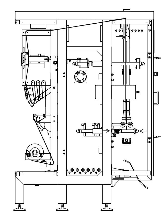
Рис.5
10. Порядок работы
Основные
узлы и элементы электрической схемы.
1. Контроллер GLOFA-GM6
2. Панель операторская
PWS 6А00 Т-P
3. Температурный
контроллер RES-403/230VAC
3. Частотный
преобразователь Altivar 31
4. Датчики,
кнопки
5. Катушки
управления, пускатели, лампочки
6. Блок
питания
1. Контроллер GLOFA-GM6.
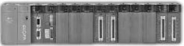
Рис.
6
Характеристики
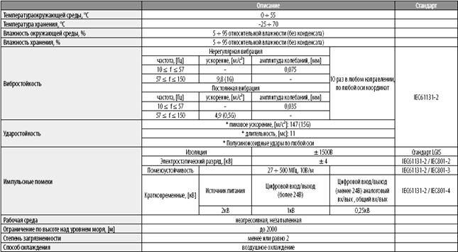
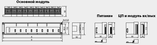
Рис. 7 Панель
управления PWS 6A00 T
Панель PWS 6A00 T оборудована жидкокристаллическим
дисплеем TFT LCD
с размером экрана 10.4” (213.2mm X 160.4mm) и
аналоговым резистивным сенсорным экраном.
Общие Технические
характеристики PWS6A00
|
PWS6A00 T-N |
PWS6A00 T-P |
|
|
Тип Дисплея |
Цветной |
|
|
Цвет дисплея |
64000 |
|
|
Размер Дисплея |
10.4″ |
|
|
Число Пикселей |
640×480 |
|
|
Регулирование Дисплея |
Контрастность, корректируемая от сенсорного экрана |
|
|
Индикатор |
CCFL; Срок службы — 50,000 часов при нормальной |
|
|
Сенсорный экран |
Аналоговый резистивный тип; Число выключателей — 80×60 Химически усиленное стекло, поддерживающее панель; Более Покрытие стойкое к большинству химическим веществам |
|
|
Входная мощность |
24VDC +/-15 %; 30W |
|
|
Выходная мощность |
5VDC +/-5 %; 100mA |
|
|
Флэш-память |
8 Mбайт |
|
|
ОЗУ |
512 кбайт |
|
|
Память с аварийным батарейным питанием |
X |
128КБ (используемый для регистров данных) |
|
Коммуникационные порты |
COM1, COM3: 9pin RS232/RS485; COM2: 25pin RS232/RS422/RS485; USB; Ethernet |
COM1, COM3: 9pin RS232/RS485; COM2: 25pin RS232/RS422/RS485; USB — |
|
Порт Принтера |
X |
«Centronics» совместимый |
|
Рабочая температура |
0~500C |
|
|
Температура хранения |
-10~600C |
|
|
Влажность окружающей среды |
20-90 % Относительная влажность |
|
|
Выносливость Вибрации |
0.5mm смещение, 10-55Hz, в течение 2 часа во всех |
|
|
Ударная Выносливость |
10g, 11ms три раза в каждом направлении X, Y, и Z осей |
|
|
Радиоизлучение |
CISPR 22, Класс A |
|
|
Разряд электростатического электричества |
IEC 801-2 Уровень 3 |
|
|
Чувствительность к радиоизлучениям |
IEC 801-3 Уровень 3 |
|
|
Переходные процессы высокой частоты |
IEC 801-4 Уровень 3 |
|
|
Вес |
1.9 Кг |
|
|
Охлаждение |
Естественное охлаждение |
Уважаемый посетитель!
Чтобы распечатать файл, скачайте его (в формате Word).
Ссылка на скачивание — внизу страницы.
Table of Contents for Ropex RESISTRON RES-403:
-
General information RES-403 Page 3 1 General information This RESISTRON temperature controller is manufac- tured according to EN 61010-1. In the course of its manufacture it passed through quality assurance, whe- reby it was subjected to extensive inspections and tests. As a result of this, the product left our factory in perfect condition. The recommendations and warning notes contained in these operating instructions must be complied
-
Controller functions Page 18 RES-403 6 Controller functions See also section 5.6 «Wiring diagram (Standard)» on page 10. 6.1 Indicators and controls Manufactured as of October 2005 Manufactured up to September 2005 In addition to the functions shown in the diagram above, various controller operating states are indicated 4 3 2 1 9 8 6 5 1 0 11 7 121314 1516 1718 AUTOCAL OUTPUT HEAT ALARM RESISTRON RES-403 Made in Germany ROPEX Tel:+49(0)7142-7776-0 Temperature controller Button for manual activation of AUTOCAL function (zero calibration). Do not press u
-
Technical data RES-403 Page 35 Digital logic levels „Temp. reached“ signal (MOD 40) or «Temp. OK» signal (MOD 46) U max =30VDC I max =50mA U ON < 2V (saturation voltage) Alarm relay U max = 30V (DC/AC), I max = 0.2A, potential-free Maximum load (primary current of impulse transformer) I max = 5A (duty cycle = 100%) I max = 25A (duty cycle = 20%) Power dissipation max. 20W Ambient temperature +5…+45°C Degree of protection IP20 Installation If several controllers are installed on one top hat rail (DIN TS35 rail), a clearance of at least 20
-
Index RES-403 Page 41 Temperature reached signal 12 , 37 Temperature setting 19 Transformer 3 , 8, 38 Type of construction 34 V View of the controller 13 Visualization software 25 W Wiring 6, 8 Wiring diagram 10 , 11
-
Controller functions RES-403 Page 23 The set point that is selected for the heatsealing tempe- rature must be greater than 40°C. If not, the heatse- aling band will not be heated up («HEAT» LED blinks). The alarm output is switched if the «START» signal is activated while an error message is indicating error codes 104…106, 111…114, 211, 302 or 303 (up to September 2005: error codes 8…12) (ª section 6.12 «Error messages» on page 26). The heatsealing band is no longer heated up. 6.6 Measuring impuls
-
Installation Page 12 RES-403 MOD 26 cannot be used in combination with MOD 40 («Temperature OK» signal) manufactured up to September 2005. 5.8 Wiring diagram with «Temp- erature reached» signal (MOD 40) or „Temp. OK“ signal (MOD 46) MOD 40 cannot be used in combination with MOD 26 (booster connection) manufactured prior to September 2005. MOD 46 cannot be used in combination with MOD 40. A dditional terminals in housing cover for MOD 26 (Booster conne
-
Installation Page 16 RES-403 5.12.2 Replacing the heatsealing band All power supply leads must be disconnected from the RESISTRON temperature controller in order to replace the heatsealing band. The heatsealing band must be replaced in accordance with the instructions provided by the manufacturer. Each time the heatsealing band is replaced, the zero point must be calibrated with the AUTOCAL function while the band is still cold, in order to compensate pro- duction-related resistance tolerances. The burn-in pro- cedure described above should be perfor
-
Controller functions Page 26 RES-403 C.) Error code output via the 0…10VDC analog output (terminals 14+15): Since a temperature indication is no longer neces- sary if a fault occurs, the analog output is used to display error messages in the event of an alarm. 13 voltage levels (up to September 2005: 12 voltage levels) are offered for this purpose in the 0…10VDC range, each of which is assigned an error code (ª section 6.12 «Error messages» on page 26). If a state that requires AUTOCAL occurs – or if the con- troller configuration is
-
Page 2 RES-403 Contents 1 General information . . . . . . . . . . . . . . . . . . 3 1.1 Intended use . . . . . . . . . . . . . . . . . . . . 3 1.2 Heatsealing band . . . . . . . . . . . . . . . . 3 1.3 Impulse transformer . . . . . . . . . . . . . . 3 1.4 Current transformer PEX-W3/-W4 . . . . 3 1.5 Line filter . . . . . . . . . . . . . . . . . . . . . . . 4 1.6 Standards / CE marking . . . . . . . . . . . 4 1.7 Maintenance . . . . . . . . . . . . . . . . . . .
-
Installation RES-403 Page 17 actual value output: The controller is functioning correctly if the tempera- ture (which corresponds to the signal change at the analog output) has a harmonious motion, in other words it must not jump abruptly, fluctuate or deviate temporarily in the wrong direction. This kind of beha- vior would indicate that the U R measuring wires have been wired incorrectly. If an error message is displayed, please proceed as described in section 6.12 «Error
-
Installation RES-403 Page 15 5.11.3 Configuration of the alarm relay If the plug-jumper is not inserted — or if it is incorrectly inserted — an error message appears when the controller is switched on (ª section 6.12 «Error messages» on page 26). If the «Alarm output opened by alarm/PC CONFIGURA- TION» position is selected (as of October 2005), the behavior of the alarm output can be configured in more detail by means of the ROPEX visualization so
Questions, Opinions and Exploitation Impressions:
You can ask a question, express your opinion or share our experience of Ropex RESISTRON RES-403 device using right now.
-
8 декабря, 2020
RES-403 Стандартные функции:
Автоматическая калибровка нуля (AUTOCAL)
Автоматическая оптимизация (AUTOTUNE)
Автоматическая компенсация фазового угла (AUTOCOMP)
Автоматическая регулировка частоты
Автоматическая настройка диапазонов вторичного напряжения и тока (АВТОМАТИЧЕСКИЙ)
Диагностический инструмент (CI-USB-1)
Важные особенности:
Выбор установки с помощью потенциометра
0… 10 В постоянного тока аналоговый выход для ФАКТИЧЕСКОЙ температуры
Управляющие сигналы 24 В постоянного тока с гальванической развязкой для START и AUTOCAL
START через беспотенциальный контакт
Сплав термосвариваемой ленты и диапазон температур (макс. 500 ° C) по выбору
Вывод и индикация неисправности (светодиод) с диагностикой ошибок