-
Contents
-
Table of Contents
-
Troubleshooting
-
Bookmarks
Quick Links
Respironics V60/V60 Plus Ventilator
User Manual
Related Manuals for Respironics V60
Summary of Contents for Respironics V60
-
Page 1
Respironics V60/V60 Plus Ventilator User Manual… -
Page 3: Table Of Contents
Table of contents Warnings, cautions, and notes ……. 1-1 Definitions ……….1-1 General.
-
Page 4
Leak adaptation ……..4-5 Auto-Trak+ (optional) . -
Page 5
Standby ……….6-20 Help function . -
Page 6
Repacking and shipping ……..10-9 Technical specifications ……..11-1 Control settings . -
Page 7
Electromagnetic compatibility declaration ….. . D-1 Electromagnetic emissions ……D-2 Electromagnetic immunity . -
Page 8
viii… -
Page 9: Warnings, Cautions, And Notes
Chapter 1. Warnings, cautions, and notes Before using the Respironics V60/V60 Plus Ventilator on a patient, familiarize yourself with this user manual, particularly the safety considerations listed. Be aware, however, that this manual is a reference only. It is not intended to supersede your institution’s protocol regarding the safe use of assisted…
-
Page 10
Do not leave the ventilator unattended when stationed on an incline. WARNING: The V60/V60 Plus Ventilator may cause radio interference or may disrupt the operation of nearby equipment. It may be necessary to take mitigation measures, such as re-orienting or relocating the ventilator or shielding the location. -
Page 11
EMC emissions or decrease the EMC immunity performance of the equipment. WARNING: Do not use the ventilator in an MRI environment. The V60/V60 Plus Ventilator is MR Unsafe. Keep it outside the MRI scan room (Zone IV). It represents a projectile hazard. -
Page 12: Preparing For Ventilation
To reduce the risk of fire, do not use a high-pressure oxygen hose that is worn or contaminated with combustible materials like grease or oil. WARNING: The Respironics V60/V60 Plus Ventilator is designed to use ambient air and high pressure 100% oxygen. No other gases should be used. WARNING: Do not use the ventilator with helium or helium mixtures.
-
Page 13
For example, positioning the ventilator next to a curtain that blocks the flow of cooling air can cause the equipment to overheat. Use the V60/V60 Plus in an upright position that does not block the air inlet. -
Page 14
Philips-supplied cord securely in place. WARNING: The V60/V60 Plus Ventilator should not be positioned in a way that makes it difficult to disconnect from mains power if necessary. Disconnect from supply mains by removing the power cord from the wall outlet. The AC mains plug is used as disconnection device. -
Page 15: Operation
SIS adapters such as the O transport manifold. NOTE: The V60/V60 Plus Ventilator is a single-limb device with substantial intentional and unintentional leak in the ventilator breathing system. Under those conditions, CO cannot be measured accurately. Therefore, we do not recommend the use of CO monitoring.
-
Page 16: Alarms And Messages
— Do not short-circuit the battery or allow metallic or conductive objects to contact the battery connector housing. — Use the battery with the Respironics V60/V60 Plus Ventilator only. WARNING: Modification of the V60/V60 Plus Ventilator and associated equipment is not permitted and may compromise ventilator operation and patient safety.
-
Page 17: First-Time Installation
(or as stipulated by your institution). CAUTION: To ensure proper system performance, use a Respironics-approved air inlet filter. CAUTION: Because some environments cause a quicker collection of lint and dust than others, inspect the filters more often when needed.
-
Page 18: Diagnostic Mode
To prevent possible patient injury due to nonannunciating alarms, verify the operation of any remote alarm device before use. WARNING: To ensure the functionality of the remote alarm, connect only Respironics- approved cables to the remote alarm port. CAUTION: The remote alarm port is intended to connect only to an SELV (safety extra-low voltage and ungrounded system with basic insulation to ground), in accordance with IEC 60601-1.
-
Page 19: Symbols
Chapter 2. Symbols Refer to these tables to interpret symbols used on the ventilator labels, backup battery labels, and packaging and on the ventilator screen. To interpret symbols pertaining to accessories, refer to their instructions for use. Table 2-1: Symbols used on ventilator labels, battery, and packaging Symbol Description Warning: Risk of explosion.
-
Page 20
Symbols Table 2-1: Symbols used on ventilator labels, battery, and packaging Symbol Description Stacking limit by number This end up Type B applied part, which is equipment that provides a particular degree of protection against electric shock, particularly in regard to allowable leakage current and of the protective earth connection Requires alternating current (AC) Degree of fluid ingress protection provided by the enclosure (drip-proof) -
Page 21
Symbols Table 2-1: Symbols used on ventilator labels, battery, and packaging Symbol Description Manufacturer. Symbol accompanied by manufacturer’s name and address. EC representative Serial number Order number Lot or batch number Model number Use by date RS-232 serial input/output USB port Oxygen (Yellow) Warning Ethernet connection… -
Page 22
Noninvasive ventilation (patient with mask) Invasive ventilation (intubated patient) The V60/V60 Plus Ventilator is MR Unsafe and presents a projectile haz- ard. Keep the ventilator outside MRI scan room (Zone IV). Do not block the cooling fan Inlet (at the rear of the ventilator). -
Page 23
Symbols Table 2-1: Symbols used on ventilator labels, battery, and packaging Symbol Description Recycle (Taiwan) 廢 電 池 請 回 收 RoHS (China). Administrative Measure on the Control of Pollution Caused by Electronic Information Products. Contains RoHS substances with 50 years environmentally friendly use period (EFUP). uR UL recognition symbol Direct current (DC). -
Page 24
Table 2-1: Symbols used on ventilator labels, battery, and packaging Symbol Description Auto-Trak+ software option High flow therapy Note: 3.00 software and above. HFT is optional for model V60 and included with model V60 Plus. Table 2-2: Symbols used on graphical user interface Symbol Description… -
Page 25
Symbols Table 2-2: Symbols used on graphical user interface (continued) Symbol Description Cancel button. Cancels set values. +2:00 minutes button. Adds two minutes to 100% O delivery. Ventilator is powered by AC power and the battery is installed. Ventilator is powered by AC power and the battery is not installed. Ventilator is powered by the battery. -
Page 26
Flow, liters per minute. BTPS compensated. Volume, milliliters User-set Ramp Time. Ramp graphic fills in as Ramp Time progresses. Ramp Time is OFF (no ramp time set). Intentional leak. The number corresponds to the leak symbol printed on Philips Respironics masks. -
Page 27: General Information
Philips-recommended patient circuits, interfaces (masks), humidifiers, and other accessories. Indications for use The Respironics V60/V60 Plus is an assist ventilator and is indicated for use to augment patient breathing. The ventilator is indicated for spontaneously breathing individuals who require mechanical ventilation: patients with respiratory failure, chronic respiratory insufficiency, or obstructive sleep apnea in a hospital or other institutional settings under the direction of a physician.
-
Page 28: Contraindications
General information Contraindications The Respironics V60/V60 Plus Ventilator is contraindicated for patients with any of the following conditions: • Lack of spontaneous respiratory drive • Inability to maintain a patent airway or adequately clear secretions • At risk for aspiration of gastric contents •…
-
Page 29: General Description
Flow and O percentage settings are selected by the clinician. HFT is available for 3.00 software and above, as well as for the V60 Plus. Auto-Trak Sensitivity allows the ventilator to automatically compensate for intentional and unintentional leaks by maintaining a stable baseline and adjusting trigger and cycle thresholds for optimum patient-to-ventilator synchrony.
-
Page 30: Physical Description
RS-232 port. Physical description Patient circuits, masks/patient interfaces, and accessories Figure 3-2 shows the Respironics V60/V60 Plus Ventilator with its patient circuit and accessories. Appendix C provides ordering information for parts and accessories.
-
Page 31
General information Bacteria filter Mask Oxygen monitor Humidifier Patient circuit Oxygen cylinder Figure 3-2: Respironics V60/V60 Plus Ventilator with accessories… -
Page 32: Ventilator Unit
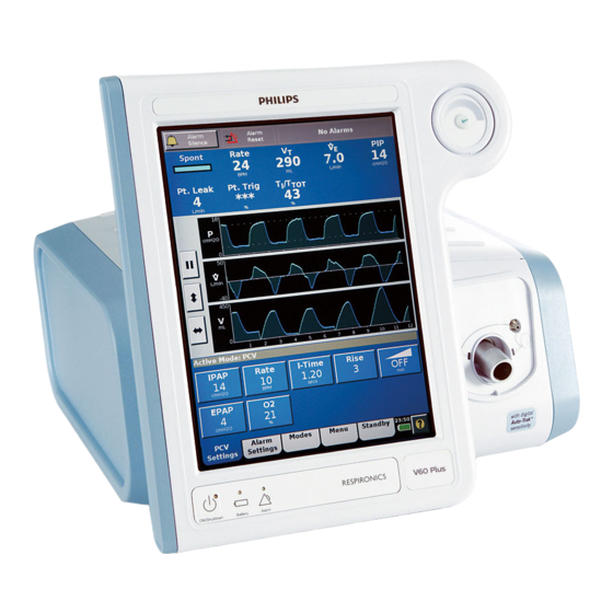
General information Ventilator unit Figure 3-3 through Figure 3-5 show the controls, indicators, and other important parts of the ventilator unit. Key panel Figure 3-3: Front view Number Description Graphical user interface. Color LCD (liquid crystal display) with touchscreen. Navigation ring. Lets you adjust values and navigate the graphical user interface by rotating the finger on its touchpad.
-
Page 33
General information Number Description Battery (charged) LED. Flashes when battery is charging. On continuously when battery is charged. Off when ventilator is running on battery, when a battery er- ror or failure is detected, or when the ventilator is off and AC power is not con- nected. -
Page 34
General information 5 4 3 2 Figure 3-5: Rear view Number Description Backup battery (compartment under side panel). Remote alarm/nurse call connector Reserved for future use Power cord retainer Power cord RS-232 serial connector (female DB-25). Connects to hospital information systems and other serial devices. -
Page 35: About The Backup Battery
General information About the backup WARNING: To reduce the risk of power failure to the ventilator, pay close attention to the battery’s charge level. The battery’s operation time is approximate and battery is affected by ventilator settings, discharge and recharge cycles, battery age, and ambient temperature.
-
Page 36
General information CAUTION: Avoid allowing the ventilator battery to become completely discharged. Otherwise, the battery may become over-discharged and require long recharge times of up to 16 hours or more. The over- discharged condition may permanently damage the battery so that it is unable to recharge. -
Page 37: About The Graphical User Interface
General information About the graphical Through the graphical user interface (Figure 3-7) you make ventilator settings and view ventilator and patient data. During ventilation, the upper screen user interface displays alarms and patient data. The middle screen displays real-time waveforms and alarm and informational messages. The lower screen lets you access modes and other ventilator settings, display help information, and see the power status.
-
Page 38: Navigating The Graphical User Interface
General information Navigating the graphical user interface Select a function by touching the desired tab or button on the touchscreen. Use this as the primary method to control the ventilator. You can use the navigation ring as an alternative to the following touchscreen functions: Touchscreen equivalent Navigation ring equivalent…
-
Page 39: Starting Up The Ventilator
General information Starting up the NOTE: Upon power-on the ventilator automatically runs a test of the backup audible alarm followed by the primary audible alarm. You should hear ventilator a high-pitched tone, followed by a beep. If you do not hear all of these sounds, discontinue use of the ventilator and have it serviced.
-
Page 40
General information 3-14… -
Page 41
Chapter 4. Principles of operation System operational The Respironics V60/V60 Plus Ventilator is a microprocessor-controlled pneumatic system that delivers a mixture of air and oxygen. It is powered by overview AC with battery backup to protect against power failure or unstable power and to facilitate intrahospital transport. -
Page 42: Principles Of Operation
CO removal. Breath delivery Control variable Breaths delivered by the Respironics V60/V60 Plus Ventilator are pressure characteristics controlled. In the AVAPS mode, the ventilator’s applied pressure is automatically adjusted over a period of time to maintain a target tidal volume.
-
Page 43: Pressure Rise Time
Auto-Trak Sensitivity An important characteristic of the Respironics V60/V60 Plus Ventilator is its ability to recognize and compensate for intentional and unintentional leaks in the system, and to automatically adjust its triggering and cycling algorithms to maintain optimum performance in the presence of leaks.
-
Page 44
Principles of operation Shape signal method of cycling and triggering. The shape signal or “shadow trigger” method uses a mathematical model derived from the flow signal. A new flow signal (shape signal) is generated by offsetting the signal from the actual flow and delaying it (Figure 4-2). -
Page 45: Leak Adaptation
Principles of operation Leak adaptation Noninvasive ventilation in particular may involve considerable leakage around the mask or through the mouth. Some leakage is known or intentional: it is a characteristic of the mask/patient interface design. So that it can accurately adjust its baseline flow, the ventilator has you enter the intentional leakage value specific to the mask/patient interface (“Selecting the mask and exhalation port”…
-
Page 46: Auto-Trak+ (Optional)
Volume adjustment Figure 4-5: Tidal volume adjustment Auto-Trak+ (optional) The Auto-Trak+ option for the Respironics V60/V60 Plus Ventilator lets you further adjust the level of Auto-Trak Sensitivity, a feature that recognizes and compensates for intentional and unintentional leaks. This algorithm has multiple breath trigger and cycle thresholds.
-
Page 47: Ventilation Modes
Patient alarms are not available during high flow therapy. This therapy is not considered a breath delivery mode. HFT requires 3.00 software and above. Ventilation modes The Respironics V60/V60 Plus Ventilator operates in the following ventilation modes: • CPAP (continuous positive airway pressure) mode •…
-
Page 48: Cpap Mode
Principles of operation CPAP mode In the CPAP (continuous positive airway pressure) mode, the ventilator functions as a demand flow system, with the patient triggering all breaths and determining their timing and size. The patient triggers and cycles based on the ventilator’s Auto-Trak Sensitivity algorithms.
-
Page 49: Pcv Mode
Principles of operation PCV mode The PCV (pressure-controlled ventilation) mode delivers pressure-controlled breaths, either triggered by the ventilator (Timed) or the patient (Spont). The control settings active in the PCV mode are shown in Figure 4-8. The IPAP setting defines the applied inspiratory pressure for all breaths. If the patient fails to trigger a breath through Auto-Trak within the interval determined by the rate setting, the ventilator triggers a mandatory breath.
-
Page 50: S/T Mode
Principles of operation S/T mode The S/T (spontaneous/timed) mode guarantees breath delivery at the user-set rate. It delivers pressure-controlled, time-cycled mandatory and pressure- supported spontaneous breaths, all at the IPAP pressure level. If the patient fails to trigger a breath within the interval determined by the Rate setting, the ventilator triggers a mandatory breath with the set I-Time.
-
Page 51: Avaps Mode
Principles of operation AVAPS mode NOTE: When you adjust AVAPS minimum and maximum pressures, remember that IPAP is adjusted to meet the target value. If the calculated target pressure is outside of the minimum and maximum pressure range, the target volume will not be achieved. Unlike most pressure modes, the AVAPS (average volume-assured pressure support) mode delivers a target tidal volume.
-
Page 52
Principles of operation Max P Mandatory (Timed) Rise breath Min P EPAP I-Time Patient-triggered (Spont) 1/Rate spontaneous breath Time Figure 4-13: AVAPS waveforms 4-12… -
Page 53: Ppv Mode (Optional)
Principles of operation PPV mode (optional) The PPV (proportional pressure ventilation) mode provides patient-triggered breaths that deliver pressure in proportion to patient effort. Additionally a user- settable backup rate activates machine-triggered, pressure-limited, and time- cycled breaths in the case of apnea. In the PPV mode, patient effort determines the pressure, flow, and tidal volume delivered by the ventilator.
-
Page 54
Principles of operation setting. If the patient fails to trigger a breath within the interval determined by the Rate control, the ventilator triggers a Timed (backup) breath with the set I-Time, Rise, and IPAP settings. The control settings active in the PPV mode are shown in Figure 4-14. Figure 4-14: PPV controls Figure 4-15 shows PPV mode waveforms. -
Page 55: Oxygen Mixing
Principles of operation Oxygen mixing The ventilator’s oxygen mixer regulates and proportions oxygen into the air from the blower according to the O setting. The delivered oxygen accuracy is ±5% of the set value up to the maximum oxygen flow available. The ventilator can deliver up to 240 L/min of air/oxygen mix to assist in managing uncontrolled leaks during noninvasive ventilation.
-
Page 56
Principles of operation 4-16… -
Page 57: Setting Up The Ventilator For Use
The Analytical Industries 2000M monitor includes user-settable high and low oxygen % alarms and is approved for use with the V60/V60 Plus Ventilator. Refer to the monitor instructions for use for detailed instructions on the proper setup and operation of the oxygen monitor.
-
Page 58: Connecting To Ac Power
WARNING: Do not use extension cords, adapters, or power cords with the ventilator that are not approved by Respironics. WARNING: To prevent unintentional disconnection of the power cord, always use the correct, Philips-supplied power cord and lock it into place with the power cord retainer before you switch the ventilator on.
-
Page 59: Installing The Patient Circuit
To prevent patient or ventilator contamination, always use a main flow bacteria filter on the patient gas outlet port. Filters not approved by Respironics may degrade system performance. WARNING: During ventilation, patient exhalate is released into room air. Use of a patient circuit with a filter on its exhalation port is recommended.
-
Page 60
Setting up the ventilator for use Assemble the patient circuit, including the main flow (inspiratory) bacteria filter, proximal pressure line, oxygen sensor tee, and if desired, humidifier and nebulizer. Figure 5-2 and Figure 5-3 show circuit configurations for noninvasive and invasive ventilation. Follow the manufacturers’ instructions for use for the individual parts. -
Page 61
Setting up the ventilator for use NOTE: This circuit setup is recommended for noninvasive ventilation. Proximal pressure port Ventilator outlet Oxygen sensor tee Bacteria filter Proximal pressure line Figure 5-2: Noninvasive patient circuit, without humidification… -
Page 62: Connecting External Devices
The Respironics V60/V60 Plus Ventilator can communicate with a Philips patient monitor using the IntelliBridge Open Interface. See “Using Philips monitors and the IntelliBridge or VueLink Open Interfaces” on page B-2. The ventilator also supports the VueLink Open Interface.
-
Page 63: Before Placing A Patient On The Ventilator
Setting up the ventilator for use Before placing a WARNING: To ensure the ventilator’s safe operation, always verify ventilator operation as described in “Verify ventilator operation” on page 5-7 before patient on the using the ventilator on a patient. If the ventilator fails any tests, remove it ventilator from clinical use immediately.
-
Page 64: Running Alarm Tests
Setting up the ventilator for use d. VERIFY that the blue “Running on Internal Battery” message is displayed. 6. Install a fully-charged battery and reconnect the ventilator to AC power. 7. Repeat step 5 to verify that the ventilator switches over to battery power.
-
Page 65: Low Tidal Volume
Setting up the ventilator for use Low Tidal Volume 1. Raise the Lo V alarm setting above the displayed, measured V 2. VERIFY that the alarm is activated. Low Tidal Volume 3. Turn the Lo V alarm setting OFF. 4. VERIFY that the alarm resets. Patient Disconnect 1.
-
Page 66: Using The Ventilator For Intra-Hospital Transport
WARNING: The V60/V60 Plus Ventilator requires a pressurized oxygen supply that provides a minimum flow of 175 SLPM. Do not use any devices such as valves, hoses, Grab n’ Go regulators or other brands of combined cylinder/ regulators that limit supply of oxygen flow below 175 SLPM.
-
Page 67: Storing The Ventilator Between Patient Use
Setting up the ventilator for use 95 100 Leak of 10 L/min Leak of 20 L/min Leak of 30 L/min Leak of 40 L/min Leak of 50 L/min a. V = 500 mL, Rate = 40 BPM, EPAP = 6 cmH O, IPAP = 18 cmH 95 100 Leak of 20 L/min…
-
Page 68: Mri Safety Information
Setting up the ventilator for use MRI safety WARNING: The V60/V60 Plus Ventilator is MR Unsafe. Keep it outside the MRI scan room (Zone IV). It represents a projectile hazard. information 5-12…
-
Page 69: Operation
Chapter 6. Operation WARNING: To ensure the ventilator’s safe operation, always verify ventilator operation as described in “Verify ventilator operation” on page 5-7 before using the ventilator on a patient. If the ventilator fails any tests, remove it from clinical use immediately. Do not use the ventilator until necessary repairs are completed and all tests have passed.
-
Page 70: Changing The Mode
Operation Changing the mode The active ventilation mode is displayed in the bottom, left-hand corner of the screen. Change the mode as follows. For details on modes, see “Ventilation modes” on page 4-7. 1. Open the Modes window. 2. Select the desired mode. Active mode 3.
-
Page 71: Changing Control Settings
Operation Changing control Table 6-3 on page 6-23 is an alphabetical list of the control settings with their ranges. Table 11-2 on page 11-2 shows the control settings applicable to the settings different modes. For more information on control settings as they apply in the different ventilation modes, see “Ventilation modes”…
-
Page 72: Changing Individual Ventilator Settings
Operation Changing individual ventilator settings You can make ventilator settings from the Settings window. 1. Open the Settings window. 2. Select the desired setting. As an example we will show the IPAP adjustment. 3. The setting window opens. Adjust the setting. Select Accept to apply. Adjustment Setting range scale arrow button…
-
Page 73: Using The Ramp Time Function
Operation Using the Ramp Time The Ramp Time function helps your patient adapt to ventilation by gradually increasing inspiratory and expiratory pressure (IPAP and EPAP/CPAP) from function subtherapeutic to user-set pressures over a user-set interval. Table 6-3 on page 6-23 describes this function’s principles of operation. Follow these instructions to use the Ramp Time function: 1.
-
Page 74: Using The 100% O2 Function
Operation Using the 100% O NOTE: The 100% O feature is available in Revision 2.30 software and above. function The 100% O function delivers 100% oxygen to the patient. It is available during Screen Lock status. Follow these instructions to use the 100% O function: 1.
-
Page 75: Using Ppv
Operation Using PPV Follow these instructions to set up the ventilator in the PPV mode, referring to Figure 6-3. For principles of operation, see “PPV mode (optional)” on page 4-13. 1. Open the PPV Settings window. 2. Set EPAP, O , alarm limits, and backup settings to appropriate values.
-
Page 76
Operation Max V Inspiration terminated Max V Sudden increase in flow Time Figure 6-1: PPV waveform – Max V limit When the Max P (PPV maximum pressure limit) is reached, pressure is limited but the breath is not terminated, and a message is displayed. After the limit is reached in three consecutive breaths, the audible alarm sounds. -
Page 77: Guidelines For Using Ppv
Operation Guidelines for using PPV NOTE: The guidelines below are based on recommendations by clinicians. They do not replace the clinical judgment of a physician and should not, on their own, be used for clinical decision making. Determining Max R and Max E settings It is recommended you set Max R (flow assist) and Max E (volume assist) to initial values and then titrate them based on the patient’s disease process: •…
-
Page 78
Operation 2. Adjust Max E: a. Evaluate the patient. Check whether any of these conditions is true: • The patient says they are getting too much air, pressure, or volume • The patient is using accessory muscles to actively stop inspiration •… -
Page 79
Operation Start Max R Make initial settings: titration EPAP: 4 cmH : Current setting or per prescription Max P: 25 cmH Does the patient say the air Max V: 1000 to 1500 mL is coming too fast ? PPV %: 80 to 100% Max E: 5 cmH Max R: 2 cmH O/L/s… -
Page 80: Changing Alarm Settings
Operation Changing alarm WARNING: To prevent possible patient injury, avoid setting alarm limits to extreme values, which can render the alarm system useless. settings Some ventilator alarm settings are operator adjustable. You can adjust these at any time. Table 6-4 on page 6-26 lists the alarm settings and their ranges. Review and adjust the alarm settings as follows: 1.
-
Page 81
Description ET/Trach ET or tracheostomy tube Leak 1 Mask with minimal intentional leak characteristics. En- ter Leak 1 for any of these Philips Respironics masks: • Contour Deluxe nasal mask • PerformaTrak mask • AF531, AF541 (EE) Leak 2 Mask with medium intentional leak characteristics. En- ter Leak 2 for this mask: •… -
Page 82
Not allowed with current mask is displayed. NOTE: In ventilation modes, ET/tracheostomy tubes and most Philips Respironics masks require the use of an exhalation port. If you selected ET/Trach or Leak 1 as a mask/patient interface, you may not select None as an exhalation port. -
Page 83
Exhalation port test Port type recommended? Philips Respironics Disposable Exhalation Port Whisper Swivel Philips Respironics Whisper Swivel Philips Respironics Plateau Exhalation Valve Other Exhalation port not supplied by Philips Respi- ronics. None No inline circuit exhalation port NOTE: If you select None, refer to the manufacturer’s instructions to make sure the mask selected contains an exhalation port. -
Page 84: Running The Exhalation Port Test
Operation Running the The exhalation port test is required and its window is automatically displayed when PEV or Other is selected. exhalation port test Procedure Run the test as follows: 1. Disconnect the patient circuit from the mask/patient interface. 2. Occlude the circuit outlet. Select Start Test. 3.
-
Page 85: Troubleshooting
Operation 5. Reconnect the patient circuit to the mask/interface. 6. Select Start Ventilation to initiate ventilation. Troubleshooting If Test Failed is displayed, check for leaks in the patient circuit, and install an exhalation device with lower leak characteristics. Repeat test. If the exhalation port test fails again, the intentional leak is unknown and Tot.Leak rather than Pt.
-
Page 86: Mask/Port
Operation Mask/Port See “Selecting the mask and exhalation port” on page 6-12. Vent Info (ventilator information) The Ventilator Information window displays software version and other information specific to your ventilator. Screen Lock Screen Lock deactivates all buttons and tabs on the touchscreen except Alarm Silence, Alarm Reset, the Alarm/Message button, and Help.
-
Page 87
Operation 2. Select the desired adjustment. As an example, the E-Cycle adjustment is shown below. 3. The setting window opens. Adjust the setting, referring to the pressure-time graphic which represents the effect on I-Time. Select Accept to apply. Proposed value When Auto-Trak+ is active (when either Trigger or E-Cycle is set to a value other than Normal), the ventilator setting window displays Auto-Trak+. -
Page 88: Standby
Operation Standby Standby lets you safely suspend ventilation to temporarily disconnect the patient from the ventilator or to set up the ventilator before connecting the patient. Alarms are disabled during standby. You can also change ventilator settings and most menu functions during standby.
-
Page 89
Operation 2. Disconnect the patient from the ventilator now. The ventilator enters standby and displays the Standby screen. 3. To resume ventilation, reconnect the patient. When the ventilator senses a patient breathing effort, ventilation automatically resumes in the previous mode. NOTE: You can also manually resume ventilation with the Restart Mode button. -
Page 90: Help Function
Operation Help function Select the help button to display additional information. Help messages are displayed: Help message 6-22…
-
Page 91: Table Of Modes And Control Settings
Operation Table of modes and control settings Table 6-3: Modes and control settings with ranges Setting Description Range Modes Modes Ventilation mode AVAPS, CPAP, S/T, PCV Optional: PPV Control settings C-Flex Enhances traditional CPAP by reducing the OFF, 1 to 3 Pressure relief pressure at the beginning of exhalation––a time when patients may be uncomfortable…
-
Page 92
Operation Table 6-3: Modes and control settings with ranges (continued) Setting Description Range I-Time (Inspira- Time to deliver the required gas. Inverse ra- 0.30 to tory Time) tio ventilation is not allowed. 3.00 secs Resulting I:E Shows where I:E ratio ratio becomes inverse Max E… -
Page 93
Operation Table 6-3: Modes and control settings with ranges (continued) Setting Description Range Min P (AVAPS The minimum pressure to be applied. 5 to 30 cmH Minimum IPAP Pressure) NOTE: When you adjust the AVAPS minimum and maximum pressures, remember that IPAP is adjusted to meet the target value. -
Page 94
Operation Table 6-3: Modes and control settings with ranges (continued) Setting Description Range Trigger Trigger Sensitivity. Auto-Trak+ employs several algorithms to determine the point at which Normal, +1 to (optional) the inspiration begins. The larger the value, the more sensitive the trigger (that is, the pa- tient can trigger inspiration with less effort). -
Page 95
Operation Table 6-4: Alarm settings (continued) Setting Description Range NOTE: In the S/T and PCV modes, the LIP alarm should be set 3-5 cmH O below the IPAP level. When set in this manner, the alarm works in conjunction with the LIP T alarm to indicate if there is a failure to trigger between the two pressure levels. -
Page 96
Operation 6-28… -
Page 97
Chapter 7. High flow therapy The high flow therapy (HFT) feature is available for 3.00 software and above, as well as V60 Plus. HFT is accessed from the Standby mode. For more information, see “Standby” on page 6-20. For principles of operation, see “High flow therapy” on page 4-6. -
Page 98: High Flow Therapy
High flow therapy High flow nasal Use either the AC611 high flow nasal cannula with FEP Connector (Figure 7-1) or the AC611 high flow nasal cannula 22 mm (Figure 7-2), which connects cannula setup directly to the patient circuit. Using the FEP Connect for high flow therapy NOTE: This section applies only if you are using the AC611 high flow nasal cannula with filter exhalation port (FEP) connector (“FEP Connect”)
-
Page 99: Changing From Ventilation To High Flow Therapy (Hft)
High flow therapy Proximal pressure port Proximal pressure line Tubing clips Changing from ventilation to high flow therapy (HFT) Follow the instructions in this chapter. Immediately after starting HFT disconnect the proximal pressure line from the ventilator. Changing from high flow therapy (HFT) to ventilation Follow the instructions in this chapter.
-
Page 100: Connecting Directly To A 22 Mm Circuit
22 mm connector DEP/FEP Figure 7-2: High flow nasal cannula, 22 mm connection Changing from an NIV Follow these instructions to use the V60/V60 Plus Ventilator for high flow therapy (HFT). mode to high flow therapy 1. Select Standby. The Entering Standby window opens.
-
Page 101: Viewing And Pausing The Hft Graph
High flow therapy 5. From the Active Mode window, you can adjust Flow and O 6. Press Start HFT. 7. The High Flow Therapy Active message is displayed during HFT. 8. Apply the HFT interface to the patient. 9. Note the low priority alarm stating that patient alarms are disabled during HFT.
-
Page 102: Changing From High Flow Therapy To An Niv Mode
High flow therapy Changing from high 1. Verify that the high flow nasal cannula is removed from the patient and disconnected from patient circuit. flow therapy to an NIV mode 2. Select Standby to open the Standby window. 3. Press the Enter Standby button. 4.
-
Page 103
High flow therapy Table 7-1: HFT Alarm and other messages: summary and troubleshooting Priority Manually Autores Silence Message Description Corrective Action type (ID) resettable ettable able Cannot Reach Target Displays when HFT (high Check the patient. Check Flow flow therapy) is active. In- that the high flow nasal (66) dicates that flow target is… -
Page 104
High flow therapy… -
Page 105: Patient Monitoring
Chapter 8. Patient monitoring The ventilator displays numeric patient data in the patient data window and real-time graphics in the waveform window (Figure 8-1). Numeric patient data is updated every breath.Table 8-1 on page 8-2 lists the ventilator’s monitored parameters. Breath phase/trigger indicator…
-
Page 106: Table Of Monitored Parameters
Patient monitoring Table of monitored parameters Table 8-1: Monitored parameters Parameter Definition Patient data window Breath phase/trigger indicator Spont (spontaneous): Inspiratory phase, patient-triggered breath (color: turquoise) Timed: Inspiratory phase, ventilator-triggered breath (color: orange) Exhale: Expiratory phase (color: blue) Peak inspiratory pressure. The highest patient pressure during the previous breath cycle. Pt.
-
Page 107: Freezing And Unfreezing Waveforms
Patient monitoring Freezing and Freeze waveforms for extended viewing by selecting the pause button to the left of the waveform window. unfreezing waveforms The cursor makes one complete sweep across the waveform and then displays the pause in progress symbol. The graphic display is then frozen, and the cursor is visible in the middle of the display (Figure 8-2).
-
Page 108
Patient monitoring… -
Page 109
Chapter 9. Alarms, messages, and troubleshooting Alarms and messages on the ventilator alert you to situations that require your attention. The ventilator can also actuate remote alarms. Figure 9-1 on page 2 shows the visual alarm characteristics. Table 9-3 on page 9-7 summarizes the different types of alarm and tells you how to respond to each. -
Page 110: Alarms, Messages, And Troubleshooting
Alarms, messages, and troubleshooting Alarm status bar (nonalarm status) No active alarms Alarm Reset Alarm button button (active) (active) Up arrows indicate that you can hide message in Alarms/ Messages list Alarm status bar Alarm Silence (active alarm status) button (active) Autoreset alarm (strikeout line through message) Waveforms…
-
Page 111
Alarms, messages, and troubleshooting Table 9-1: Alarm summary Alarm LED on front Alarm message in Remote Status panel Alarm status bar Alarms list Audio Action required alarm No alarms None None Autoreset Red (high- Background color alarm priority) or yellow same as that of (low-priority) active alarm. -
Page 112: Setting Alarm Loudness
Alarms, messages, and troubleshooting Figure 9-2: Vent Inoperative screen Setting alarm You can set the alarm loudness from the Menu window (see “Loudness” on page 6-17). loudness…
-
Page 113: Silencing Alarms
Alarms, messages, and troubleshooting Silencing alarms Silence an alarm for 2 minutes by selecting the Alarm Silence button. The button icon is replaced by this one. A timer shows time remaining in the 2-minute alarm silence period. Select Alarm Silence again at any time to reset the counter to 2:00 minutes. During patient maneuvers, you can pre-silence audible alarms as desired.
-
Page 114: Hiding/Displaying Alarm Messages
Alarms, messages, and troubleshooting Hiding/displaying To hide an alarm or informational message in the Alarms or Messages list, touch the flashing alarm indicator button or informational message button alarm messages when up arrows are present. To display messages, touch the flashing alarm indicator or Informational Message button when down arrows are present.
-
Page 115: Alarms And Other Messages
Alarms, messages, and troubleshooting Table 9-2: Symptom-based troubleshooting (continued) Symptom Recommended Action The estimated exhaled tidal volume reading (V ) is inaccurate. Check the patient. Check for large leaks. Make sure ventilator and alarm settings are appropriate. Make sure an approved patient circuit is in use. Adjust the mask to ensure proper fit and adequate leak com- pensation.
-
Page 116
Alarms, messages, and troubleshooting Table 9-3: Alarm and other messages: summary and troubleshooting (continued) Priority Manually Autores Silence Message Description Corrective Action type (ID) resettable ettable able Cannot Reach Target Displays when HFT (high Check the patient. Check Flow flow therapy) is active. In- that the high flow nasal (53) dicates that flow target is… -
Page 117
Alarms, messages, and troubleshooting Table 9-3: Alarm and other messages: summary and troubleshooting (continued) Priority Manually Autores Silence Message Description Corrective Action type (ID) resettable ettable able Low Internal Battery Battery can provide oper- Connect ventilator to AC High ating power for only an ad- power. -
Page 118
Alarms, messages, and troubleshooting Table 9-3: Alarm and other messages: summary and troubleshooting (continued) Priority Manually Autores Silence Message Description Corrective Action type (ID) resettable ettable able Low Rate A low-priority alarm if the Check the patient. Con- Low/ measured respiratory rate firm ventilator and alarm High is less than the Lo Rate… -
Page 119
Alarms, messages, and troubleshooting Table 9-3: Alarm and other messages: summary and troubleshooting (continued) Priority Manually Autores Silence Message Description Corrective Action type (ID) resettable ettable able Patient Circuit Oc- Displays when HFT (high Check the patient. Check High cluded flow therapy) is active. -
Page 120
Alarms, messages, and troubleshooting Table 9-3: Alarm and other messages: summary and troubleshooting (continued) Priority Manually Autores Silence Message Description Corrective Action type (ID) resettable ettable able PPV Maximum Vol- Estimated delivered pa- Check the patient. Con- Infor- tient tidal volume is great- firm ventilator and alarm mation/ er than the PPV maximum… -
Page 121
Alarms, messages, and troubleshooting Table 9-3: Alarm and other messages: summary and troubleshooting (continued) Priority Manually Autores Silence Message Description Corrective Action type (ID) resettable ettable able Using Default Set- Displayed after power on Check the patient. Check Infor- tings if setting values are cor- and adjust settings as re- mation… -
Page 122
Alarms, messages, and troubleshooting Table 9-4: Check Vent alarm messages: summary and troubleshooting (continued) Priority Manually Autores Silence Message Description Corrective Action type (ID) resettable ettable able Check Vent: Aux Backup alarm problem Check the patient. Provide High Supply Failed alternative ventilation. -
Page 123
Alarms, messages, and troubleshooting Table 9-4: Check Vent alarm messages: summary and troubleshooting (continued) Priority Manually Autores Silence Message Description Corrective Action type (ID) resettable ettable able Check Vent: CPU Technical failure Check the patient. Provide High PCBA ADC Failed alternative ventilation. -
Page 124
Alarms, messages, and troubleshooting Table 9-4: Check Vent alarm messages: summary and troubleshooting (continued) Priority Manually Autores Silence Message Description Corrective Action type (ID) resettable ettable able Check Vent: O Pres- Continues to ventilate Check the patient. Provide High sure Sensor Calibra- with air only alternative ventilation. -
Page 125
Alarms, messages, and troubleshooting Table 9-5: Vent Inoperative alarm messages: summary and troubleshooting Priority Manually Autores Silence Message Description Corrective Action type (ID) resettable ettable able Vent Inoperative Technical failure. The Check the patient. Provide al- High 1000 ventilator is in the ven- ternative ventilation. -
Page 126
Alarms, messages, and troubleshooting Table 9-5: Vent Inoperative alarm messages: summary and troubleshooting (continued) Priority Manually Autores Silence Message Description Corrective Action type (ID) resettable ettable able Vent Inoperative Technical failure. The Check the patient. Provide al- High 1009 ventilator is in the ven- ternative ventilation. -
Page 127
Disinfection is most effective on medical devices that were previously cleaned. NOTE: For all V60/V60 Plus hardware accessories recommended by Philips, follow the cleaning and disinfection guidelines in this chapter. For multi-patient interface and circuit accessories, consult the product For single patient use accessories, no cleaning instructions for use. -
Page 128: Care And Maintenance
Care and maintenance Exterior and CAUTION: To prevent possible damage to the ventilator, use only those cleaning and disinfecting agents listed in this manual. touchscreen cleaning CAUTION: To prevent possible damage to the ventilator, do not drip or spray any liquids directly onto any surface including the front panel, touchscreen, and navigation ring.
-
Page 129: Exterior And Touchscreen Disinfection
Care and maintenance Exterior and CAUTION: To prevent possible damage to the ventilator, use only those cleaning and disinfecting agents listed in this manual. touchscreen CAUTION: To prevent possible damage to the ventilator, do not drip or spray any disinfection liquids directly onto any surface including the front panel, touchscreen, and navigation ring.
-
Page 130: Bacteria Filter, Patient Circuit, And Other Accessories
Because some environments cause a quicker collection of lint and dust than others, inspect the filters more often when needed. The air inlet filter should be replaced; the cooling fan filter should be cleaned. CAUTION: To ensure proper system performance, use a Respironics-approved air inlet filter. 10-4…
-
Page 131: Preventive Maintenance
Care and maintenance Preventive WARNING: Only authorized service personnel should replace parts within the ventilator or perform other service activities. Unauthorized personnel maintenance without proper training are at risk of electric shock. WARNING: Turn off the ventilator and disconnect it from the AC mains outlet before you perform decontamination or maintenance procedures.
-
Page 132: Replacing The Air Inlet Filter
Care and maintenance Replacing the air inlet filter Replace the air inlet filter as follows, referring to Figure 10-1. 1. Power down the ventilator and disconnect it from AC power. Remove ventilator from cart, if applicable. 2. Turn the captive D-ring fastener counter-clockwise one-quarter turn and release.
-
Page 133: Cleaning Or Replacing The Cooling Fan Filter
Care and maintenance Cleaning or replacing the cooling fan filter Clean or replace the cooling fan filter as follows, referring to Figure 10-2: 1. Insert a small, flat blade driver tip between the foam filter and the filter retaining cover (Figure 10-2). 2.
-
Page 134: Removing And Replacing The Battery
Care and maintenance Removing and replacing the battery See “Installing the battery” on page A-4. Disposal WARNING: This product consists of devices that may contain mercury, which must be recycled or disposed of in accordance with local, state, or federal laws. (Within this system, the backlight lamps in the monitor display contain mercury.) Dispose of all parts removed from the device according to your institution’s…
-
Page 135: Service And Repairs
For technical service or repair information not included in this chapter, contact Philips. A V60/V60 Plus service manual is available (order number 989805612651, part number 1049766), and can also be downloaded from www.philips.com/ hrcmanuals. The service manual includes removal and installation procedures, parts lists, and testing and troubleshooting information.
-
Page 136
Care and maintenance 10-10… -
Page 137: Technical Specifications
4 cmH target) Flow 10 to 80 L/min 5 L/min 35 L/min (High flow therapy, 3.00 software and above, and V60 Plus) IPAP 4 to 40 cmH 1 cmH ± (2 cmH O + 4% of 12 cmH target) I-Time (Inspiratory 0.30 to 3.00 sec…
-
Page 138
Rise (Rise Time) 1 to 5 (AVAPS Target Tidal 200 to 2000 mL BTPS 5 mL ± 15% 500 mL Volume) Table 11-2: Controls active in Respironics V60/V60 Plus ventilation modes CPAP AVAPS Timing Rate Rate I-Time I-Time* Baseline pressure… -
Page 139: Patient Data
Technical specifications Patient data Table 11-3: Patient data ranges, resolutions, and accuracies during ventilation Parameter Range Resolution Accuracy Patient data window Breath phase/trigger indicator Spont, Timed, Exhale Color-coded display: Spont — turquoise, Timed — orange, Ex- hale — blue 0 to 50 cmH 1 cmH ±…
-
Page 140: Alarms
Exhalation Port Selection • DEP (Philips Respironics Disposable Exhalation Port • Whisper Swivel (Philips Respironics Whisper Swivel), • PEV (Philips Respironics Plateau Exhalation Valve), • Other (Other Exhalation Port), • None (No circuit exhalation port) Screen Lock Off, On Auto-Trak+ (optional) Trigger: Normal, +1 to +7.
-
Page 141: Diagnostic Mode Functions
Technical specifications Diagnostic mode Table 11-6: Diagnostic mode functions functions Function Range Language English, Nederlands, Français, Deutsch, Italiano, Por- tuguês, Español, Dansk, Suomi, Norsk, Svenska, Chi- nese, Japanese, Türkçe Date/Time Pressure Units O, hPa Restore Default Settings Software Options Baud Rate 9,600, 19,200, 115,200 Alarm Volume Escalation Enable, Disable (default)
-
Page 142: Physical Characteristics
12 kg (26 lb) with battery V60/V60 Plus ventilator in its most usual configuration Installed weight V60/V60 Plus Ventilator with backup battery, ventila- tor stand, O tank holder, two E-cylinders (full), two (V60/V60 Plus ventilator on gauge clusters, oxygen analyzer with mount, humidifi-…
-
Page 143: Pneumatic Specifications
Pressure: 3.31 to 6.00 bar / 331 to 600 kPa / 48 to 87 psig Flow: 175 SLPM High-pressure oxygen supply Connector: DISS male, DISS female, NIST (using V60/V60 Plus manifold) Pressure: 3.10 to 6.00 bar / 310 to 600 kPa / 45 to 87 psig Flow: 175 SLPM Connector: SIS Pressure: 3.66 to 6.00 bar / 366 to 600 kPa / 53 to…
-
Page 144: Electrical Specifications
Technical specifications Electrical specifications Table 11-10: Electrical specifications Parameter Specification AC voltage 100 to 240 VAC AC frequency 50/60 Hz AC power 300 VA Battery PN 1076374: 14.4 V, 11.0 Ah, 163 Wh Maximum system current draw: 11 A Charge voltage: +16.9 V maximum Operating time: 360 minutes (6 hours) under normal conditions Accessory…
-
Page 145: Alarm-Related Specifications
Technical specifications Alarm-related specifications Table 11-12: Alarm-related specifications Parameter Specification Delay time from the onset of the < 10 ms from onset of the alarm condition to the alarm condition to the point that transmission of the signal the representation of the alarm <…
-
Page 146
Parameter Specification High flow therapy 10 to 80 L/min BTPS (3.00 software and above, and V60 Plus) NOTE: The maximum deliverable flow rate varies based on the orifice size of the nasal cannula and on the patient’s nasal passage resistance. -
Page 147
Appendix A. First-time installation WARNING: Philips-authorized personnel must install the ventilator. For information about installation, contact your Philips representative. Before putting the ventilator into service for the first time, install it as described in this chapter. Unpacking and Unpack the ventilator and inspect it for damage. Inspect the exterior cabinet of the ventilator for cracks, scratches, or blemishes. -
Page 148: First-Time Installation
Ensure that the locking lever on the back right of the stand locks into place. Figure A-1: Mounting the V60/V60 Plus Ventilator on the stand…
-
Page 149
Figure A-2 shows the installed ventilator. Use the brakes to lock and unlock the wheels as needed. Make sure the wheels are unlocked before moving the ventilator. Power cords can be stored on stand hooks Wheel lock Figure A-2: Respironics V60/V60 Plus Ventilator on stand… -
Page 150: Installing The Battery
— Do not short-circuit the battery or allow metallic or conductive objects to contact the battery connector housing. — Use the battery with the Respironics V60/V60 Plus Ventilator only. Install the battery as follows (Figure A-3). 1. Shut down and then unplug the ventilator.
-
Page 151
First-time installation 7. Attach the option label as shown in Figure 3-5 on page 3-8. WARNING: Never attempt to disconnect or connect the battery during operation. CAUTION: Following battery installation, if a Check Vent or Vent Inoperative alarm occurs when verifying ventilator operation, discontinue use of the ventilator immediately and contact Philips. -
Page 152
First-time installation Captive fastener Bracket Battery Orient with vent hole on top and Philips logo facing out Battery cable Figure A-3: Installing the battery… -
Page 153: Installing Oxygen Inlet Connector And Ac Power Cord
First-time installation Installing oxygen The Respironics V60/V60 Plus Ventilator destined for Japan, China, and the U.S. are typically pre-configured. V60/V60 Plus Ventilators shipped to other inlet connector and countries may require installation of the power cord and oxygen inlet AC power cord connector.
-
Page 154
Philips-supplied cord securely in place. WARNING: The V60/V60 Plus Ventilator should not be positioned in a way that makes it difficult to disconnect from mains power if necessary. Disconnect from supply mains by removing the power cord from the wall outlet. The AC mains plug is used as disconnection device. -
Page 155: Installing The Oxygen Manifold Kit
First-time installation Installing the oxygen If desired, install the oxygen manifold kit as described in the accompanying instructions. manifold kit Verifying ventilator Perform the following steps to verify ventilator and audible alarm operation: operation and audible 1. Assemble and install a patient circuit. (See Chapter 5 for instructions alarm on installing a patient circuit.) 2.
-
Page 156
First-time installation A-10… -
Page 157: Communications Interface
Appendix B. Communications interface WARNING: Connect to the ventilator only items that are specified as part of or compatible with the ventilator system. Additional equipment connected to medical electrical equipment must comply with the respective IEC or ISO standards. Furthermore, all configurations shall comply with the requirements for medical electrical systems (see IEC 60601-1-1 or clause 16 of edition 3 of IEC 60601-1, respectively).
-
Page 158: Rs-232 Serial Port
• Legacy (VRPT/SNDA): Fixed text-based protocol (not to be used for developing new driver interfaces). For this protocol specification, refer to the V60 Communications interface VRPT / SNDA Developers Guide (1147828MC), available at www.philips.com/IFU. Using Philips Using Philips monitors and the IntelliBridge or VueLink Open Interfaces…
-
Page 159: Data Display
Figure B-3: Connection from ventilator to Philips patient monitor Data display The data from your Respironics V60/V60 Plus Ventilator is displayed in several windows on your Philips monitor. This data may be labeled differently on the monitor than on the ventilator. Refer to Table B-1 to interpret these labels.
-
Page 160
Communications interface Table B-1: Ventilator data displayed on Philips monitor (continued) Monitor label Ventilator label STNDBY Standby Control settings sEppv Max E Not shown C-Flex PAVsup PPV % sCPAP CPAP sEPAP EPAP sfgFl Flow (in HFT) sFIO sInsTi I-Time (Inspiratory Time) sIPAP IPAP sPmax… -
Page 161: Remote Alarm Port
To prevent possible patient injury due to nonannunciating alarms, verify the operation of any remote alarm device before use. WARNING: To ensure the functionality of the remote alarm, connect only Respironics- approved cables to the remote alarm port. CAUTION: The remote alarm port is intended to connect only to an SELV (safety extra-low voltage and ungrounded system with basic insulation to ground), in accordance with IEC 60601-1.
-
Page 162
For ¼” jack. Remote alarm cable kit, Use on Normally Opened nurse call systems (system expects to 1003742 alarm state = closed see closed contacts when ventilator alarms). For ¼” jack. Remote alarm cable kit Philips Respironics (LifeCare) 1003743… -
Page 163
Respironics-approved accessories with the ventilator. For the most current list of approved accessories plus comprehensive ordering information for compatible parts available from Philips, contact your Philips representative or refer to the V60/V60 Plus ordering and accessories guide (downloadable from philips.com/V60). -
Page 164: Parts And Accessories
Respironics AF531 Respironics PerforMax, adult only Total HFT interfaces For use with V60 Plus ventilators and V60 ventilators that have 3.00 software (or higher) and the HFT option installed. Description Respironics AC611 high flow nasal cannula Respironics AC611 high flow nasal cannula, FEP Connect…
-
Page 165: Patient Breathing Circuits
Description Quantity Part number Order number Humidifiers Respiratory humidifier, Fisher & Paykel MR850 Refer to the V60 ordering and Respiratory humidifier, WILAmed AIRcon Gen2, 230V accessories guide (Not available in North America) Chambers Humidifier chamber, adult, Fisher & Paykel MR290…
-
Page 166: Bacteria Filters
Description Quantity Part number Order number Cooling fan filter 1054280 453561507301 Air inlet filter 1054279 453561505991 Other parts Compatible with all V60/V60 Plus Ventilators: Description Part number Order number Test lung, hard-sided (low-compliance) 1021671 989805611871 Backup battery 1076374 989805626941…
-
Page 167: Regulatory Compliance
EMC information provided in this document. declaration WARNING: The V60/V60 Plus Ventilator may cause radio interference or may disrupt the operation of nearby equipment. It may be necessary to take mitigation measures, such as re-orienting or relocating the ventilator or shielding the location.
-
Page 168: Electromagnetic Emissions
Guidance and manufacturer’s declaration — electromagnetic emissions The V60/V60 Plus Ventilator is intended for use in the electromagnetic environment specified below. The user of the V60/V60 Plus Ventilator should assure that it is used in such an envi- ronment. Emissions test…
-
Page 169: Electromagnetic Immunity
Guidance and manufacturer’s declaration — electromagnetic immunity The V60/V60 Plus Ventilator is intended for use in the electromagnetic environment specified below. The user of the V60/V60 Plus Ventilator should assure that it is used in such an environment. IEC 60601-1-2…
-
Page 170
Guidance and manufacturer’s declaration — electromagnetic immunity The V60/V60 Plus Ventilator is intended for use in the electromagnetic environment specified below. The customer or the user of the V60/V60 Plus Ventilator should assure that it is used in such an environment. -
Page 171
Regulatory compliance Recommended separation distances between portable and mobile RF communications equipment and the V60/V60 Plus Ventilator Separation distance according to frequency of transmitter (m) 150 kHz to 80 MHz 150 kHz to 80 MHz 80 MHz to 800 MHz 800 MHz to 2.7 GHz… -
Page 172: Rf Immunity
Regulatory compliance RF immunity Test specifications for RFID immunity The frequencies specified are not yet part of formal regulatory standard IEC 60601-1-2 4.0ED. They are based on 1) a working draft of IEC60601-1-2 4.1ED:2018 Table 11 Medical electrical equipment – Part 1-2: General requirements for basic safety and essen- tial performance –…
-
Page 173: Cables That May Affect Iec 60601-1-2 Compliance
Regulatory compliance So, in addition to selection of RFID systems and medical electrical equipment and systems, EMC management includes maintaining adequate separation distances between them. For medical electrical equipment and systems that meet this standard, the minimum necessary separation distances are shown in Annex J of the AIMS standard 7351731, as well as the guidance required by standards such as IEC 60601-1-2.
-
Page 174: Classification
Regulatory compliance Classification Protection Against Electric Class I Shock Degree of Protection Against Type B Electric Shock Degree of protection against IP21 ingress of particulate matter Protected against solid objects ≥ 12.5 mm in diameter. and water given by the enclo- Protected against vertically falling water drops when en- sure closure is tilted up to 15°…
-
Page 175: Applied Parts
Regulatory compliance Applied parts The V60/V60 Plus Ventilator system includes these applied parts: • Masks • Tracheal and endotracheal tubes • Nebulizer T-adapter • Ventilator Breathing System — Type B (inspiratory or expiratory pathways through which gas flows at respiratory pressures and…
-
Page 176
Regulatory compliance D-10… -
Page 177: Diagnostic Mode
Appendix E. Diagnostic mode In the diagnostic mode you select the language of software display, set the date and time, select pressure units, enable software options, and calibrate the touchscreen. NOTE: The diagnostic mode is primarily for use by authorized service personnel to download software and perform other diagnostic procedures.
-
Page 178
Diagnostic mode 3. Within less than 5 seconds, release and press the Accept button again. The Diagnostics Menu (Figure E-1) is displayed. Figure E-1: Diagnostics Menu 4. Select the desired function. -
Page 179: System Settings
Diagnostic mode System settings From the System Settings screen (Figure E-2) you can perform the functions below. Figure E-2: System Settings screen…
-
Page 180: Language
Diagnostic mode Language The Language function lets you set the language of software display. 1. From the System Settings screen, select Language to display the Set Language screen (Figure E-3). Figure E-3: Set Language screen 1…
-
Page 181
Diagnostic mode 2. The active language is shown in white type. Select the new language. 3. A second Set Language screen is displayed (Figure E-4). Select Ventilator Shutdown to apply the change. The change is effective after you restart the ventilator. Figure E-4: Set Language screen 2… -
Page 182: Date/Time
Diagnostic mode Date/Time The Date/Time function lets you verify date and time settings. 1. From the System Settings screen, select Date/Time to display the Set Date and Time screen (Figure E-5). Figure E-5: Set Date and Time screen 2. Adjust the date and time with the + and — buttons; then Apply.
-
Page 183: Pressure Units
Diagnostic mode Pressure Units The Pressure Units function lets you select the unit of measure for pressure display. 1. From the System Settings screen, select Pressure Units to display the Set Pressure Units screen (Figure E-6). Figure E-6: Set Pressure Units screen 2.
-
Page 184: Restore Default Settings
Diagnostic mode Restore Default Settings The Restore Default Settings function lets you return ventilator settings to factory defaults. The factory defaults are listed in Chapter 11. 1. From the System Settings screen, select Restore Default Settings to display the Restore Default Settings screen (Figure E-7). Figure E-7: Restore Default Settings screen 2.
-
Page 185: Software Options
Diagnostic mode Software Options With the Software Options function, you enable a software option using a unique code specific to the option and the ventilator serial number. Options can also be enabled through the Respi-Link remote service program. NOTE: Before installing an option, verify that the ventilator serial number matches the serial number shown in the Vent Info window (“Vent Info (ventilator information)”…
-
Page 186: Baud Rate
Diagnostic mode Baud Rate The Baud Rate function lets you set the baud rate for serial communications. 1. From the System Settings screen, select Baud Rate to display the Set Baud Rate for Serial Communications screen (Figure E-9). Figure E-9: Set Baud Rate for Serial Communications screen 2.
-
Page 187: Alarm Volume Escalation
Enabled, you will see a selectable Disable button. Press the button to change the setting. 3. The new setting is applied after the V60/V60 Plus Ventilator is shut down and powered on again. 1. Available in Revision 2.30 software and above.
-
Page 188: Service
Diagnostic mode Service NOTE: All ventilator mode and alarm settings, alarm messages and significant events are automatically logged and retained, even when power is lost. The Service screen lets you view the event log. Other service functions are for use by authorized service personnel. Significant Event Log The Significant Event Log contains data about clinically relevant ventilator occurrences, including alarms and setting changes.
-
Page 189
Diagnostic mode 3. The Significant Event Log opens (Figure E-12). Use the buttons on right side to navigate through the log. Figure E-12: Significant Event Log screen E-13… -
Page 190: Touchscreen Calibration
Diagnostic mode Touchscreen Calibrate the touchscreen X and Y coordinates as follows: calibration 1. From the Diagnostics Menu, select Touch Screen Calibration. The Touch Screen Calibration screen is displayed (Figure E-13). NOTE: If the Touch Screen Calibration button does not respond, press the Accept button on the navigation ring to begin.
-
Page 191: Exiting The Diagnostic Mode
Diagnostic mode 3. When prompted, touch the screen to exit calibration. If the calibration is not successful, have the ventilator serviced. Exiting the diagnostic Exit the diagnostic mode by turning off ventilator power with the ON/Shutdown key. mode E-15…
-
Page 192
Diagnostic mode E-16… -
Page 193: Glossary
Auto-Trak+ An optional feature that allows adjustments to trigger and cycle thresholds beyond Auto-Trak Sensitivity settings. Auto-Trak Sensitivity A Respironics innovation in triggering and cycling that utilizes several different methods to provide enhanced sensitivity in the presence of leaks and changing breathing patterns.
-
Page 194
Glossary CPAP Continuous positive airway pressure. A ventilation mode that provides a single, continuous level of positive pressure to the patient and a control setting in that mode. Cycle To end inspiration. dB(A) Decibel, a unit of acoustic power. DISS Diameter index safety standard, a standard for high-pressure gas inlet fittings. -
Page 195
Glossary hPa Hectopascal, a unit of pressure measurement. 1 hPa is equal to 1 mbar, which is approximately equal to 1 cmH ID Inner diameter. IEC International Electrotechnical Commission. I:E ratio Ratio of inspiratory to expiratory time. Inop Inoperative. Inspiration:exhalation ratio See I:E ratio. Inspiratory positive airway pressure See IPAP. -
Page 196
Glossary Max P AVAPS Maximum IPAP Pressure. A control setting in AVAPS. Max P Maximum Pressure. See PPV Maximum Pressure Limit. Max R Maximum resistance (flow assist). A control setting in PPV. Max V Maximum Volume. See PPV Maximum Volume Limit. Min P AVAPS Minimum IPAP Pressure. -
Page 197
Glossary psi Pounds per square inch. psig Pounds per square inch gauge (above atmospheric pressure). Proportional pressure ventilation see PPV. Pt. Leak The leak resulting from leaks around the mask or from unintentional leaks in the circuit. A monitored parameter shown when the intentional leak is known. -
Page 198
Glossary Time Trigger Initiation of inspiration by the ventilator according to the Respiratory Rate setting. Timed indicator Denotes machine-triggered (mandatory) breathing. Inspiratory duty cycle. Inspiratory time divided by total cycle time, averaged over 8 breaths, a monitored parameter. Tot.Leak Estimated total leak, both intentional and unintentional. A monitored parameter shown when the mask leak and type of exhalation port are not known. -
Page 199
Index AVAPS: Target V Not Achieved. Insufficient Max Pressure message 9-7 AC power Average volume-assured pressure support mode. See AVAPS how to connect to 5-2 mode specifications 11-8 AC power cord, how to install A-7–A-8 Accessories part numbers C-1–?? Backup alarm 3-9 Air inlet filter. -
Page 200
Index Check Vent: Internal Temperature High Daq alarm 9-15 how to change date and time E-6 Check Vent: Internal Temperature High Mtr alarm 9-15 how to change language E-4–E-5 Check Vent: Machine Pressure Sensor Auto-Zero Failed how to change pressure unit E-7 alarm 9-15 how to enable or disable Alarm Volume Escalation E-11 Check Vent: Machine Pressure Sensor Calibration Data Error… -
Page 201
Modes, ventilation. See Ventilation modes IntelliBridge Monitored parameters using with Philips monitors B-2–B-5 definitions 8-2 Intended use, Respironics V60 Ventilator 3-1 ranges, resolutions, and accuracies 11-3 Interface. See Patient interface or Communications inter- Mounting the ventilator A-2–A-3 face IPAP (inspiratory positive airway pressure) setting, definition… -
Page 202
3-4 how to select 6-12–6-15 location of Ethernet connector 3-8 how to test 6-16–6-17 Respiratory rate. See Rate part numbers C-2 Respironics V60 Ventilator Power cord front view 3-6 how to install A-8 physical description 3-4–3-8 location 3-8 potential side effects 3-2… -
Page 203
Index Startup alarm 9-17 time specifications 11-10 Vent Inoperative 1007 Machine and Proximal Pressure Sen- ventilator startup 3-13 sors Failed alarm 9-17 Symbols 2-1–2-8 Vent Inoperative 1008 Machine and Proximal Pressure Sen- System Settings functions, in diagnostic mode E-3 sors Failed alarm 9-17 Vent Inoperative 1009 Pressure Regulation High alarm 9-18 Vent Inoperative 100A Data Acquisition PCBA ADC Refer- ence Failed alarm 9-18… -
Page 204: Index
Index Index-6…
-
Page 206
Respironics California, LLC 2271 Cosmos Court Carlsbad, CA 92011 USA Respironics Deutschland GmbH & Co. KG Gewerbestrasse 17 82211 Herrsching Germany Australian sponsor Philips Electronics Australia Ltd 65 Epping Road North Ryde, NSW Australia 2113 You can find the most current electronic copy of this user manual at: www.philips.com/IFU…
This manual is also suitable for:
V60 plus
Аппарат ИВЛ Philips Respironics V60 — современный представитель широкой линейки аппаратов для проведения искусственной вентиляции легких от Philips.
Описание аппарата ИВЛ Philips Respironics V60
Прибор обладает различными автоматическими алгоритмами для своевременной адаптации рабочего процесса под индивидуальные потребности как пациентов, так и специалистов. К ним относятся Auto Track и более расширенная версия Auto Track Plus. А осуществление непрерывного давления в легочных путях с характерным понижением во время вдоха достигается с помощью инструмента C Flex. Помимо этого доступны 3 различных профиля с учетом коррекции других параметров. Все это необходимо для качественного улучшения самочувствия пациента на протяжении всего процесса терапии.
Основные преимущества аппарата ИВЛ Philips Respironics V60
— яркий цветной экран с наглядной демонстрацией всех необходимых параметров и диагональю в 12,1 дюймов,
— сенсорный тип управления облегчает эксплуатацию и делает ее более комфортной,
— встроенная система тревожных оповещений в случае критических изменений показателей или технических неполадок,
— интуитивно понятный интерфейс со множеством настраиваемых параметров и режимов ИВЛ инвазивным и неинвазивным методом (AVAPS, CPAP, PPV, PCV, S/T и т.д.),
— пневматический тип вентиляционного привода,
— встроенный тип аккумулятора обеспечивает рабочий процесс в автономном режиме в течение 6 часов,
— поддерживаемый дыхательный объем от 200 до 2000 мл,
— оптимизация вентиляции неинвазивным методом с помощью функции Auto Track,
— грамотное распределение времени с помощью заданных настроек,
— поддержка нескольких разновидностей лечения в зависимости от степени тяжести заболевания,
— технология AVAPS для гарантированной сохранности параметров давления,
— высокий уровень мобильности,
— оптимизированный способ интеграции в центральную систему медицинского учреждения,
— поддержка систематического обновления системы с помощью Respi Link,
— стильный эргономичный дизайн и компактные размеры.
Philips Respironics V60 использует многолетний опыт производителей, сочетает в себе альтернативное решение многих поставленных задач.

-
Contents
-
Table of Contents
-
Troubleshooting
-
Bookmarks
Related Manuals for Philips Respironics V60
Summary of Contents for Philips Respironics V60
-
Page 1
Respironics V60 Ventilator Service Manual… -
Page 2
For Technical Support and Customer Service, contact: USA and Canada: 1-800-345-6443 (toll free) or 724-387-4000 Respironics Europe, Africa, Middle East: +33-1-47-52-30-00 Respironics Asia Pacific: +852-3194-2280 Facsimile: 724-387-5012 United States of America Respironics California, Inc. 2271 Cosmos Court Carlsbad, CA 92011 Email and Web Addresses service@respironics.com clinical@respironics.com… -
Page 3: Table Of Contents
3.2.7 Flow Sensors ……… . 3-10 1049766 Rev A V60 Ventilator Service Manual…
-
Page 4
6.5.1 Programming the Ventilator Serial Number ….. 6-21 6.5.2 Programming Ventilator Power-On Hours….. . . 6-23 V60 Ventilator Service Manual 1049766 Rev A… -
Page 5
7.38 Labels ……….7-42 1049766 Rev A V60 Ventilator Service Manual… -
Page 6
8.9 Performance Verification Data Form ……8-45 V60 Ventilator Service Manual 1049766 Rev A… -
Page 7
Index……….Index-1 1049766 Rev A V60 Ventilator Service Manual… -
Page 8
Table of Contents (This page is intentionally blank.) viii V60 Ventilator Service Manual 1049766 Rev A… -
Page 9: Introduction And Intended Use
V60. Review the operating instructions for the V60 ventilator before running tests, checking operational readiness, or initiating patient use. These instructions include important information about ventilator safety and operation.
-
Page 10: Intended Use
Chapter 1 Introduction and Intended Use 1.1 Intended Use The Respironics V60 ventilator is an assist ventilator that is intended to augment patient breathing. It is intended for spontaneously breathing individuals who require mechanical ventilation: patients with respiratory failure, chronic respiratory insufficiency, or obstructive sleep apnea in a hospital or other institutional settings under the direction of a physician.
-
Page 11: Recommended Test Equipment, Tools, And Supplies
Introduction and Intended Use 1.2 Recommended Table 1-1 lists the recommended tools, test equipment, and materials required Test Equipment, to service and maintain the V60 ventilator. Tools, and Supplies Table 1-1: Recommended Test Equipment, Tools, and Materials Description Manufacturer and Model…
-
Page 12
1 to 25 in.-lbf Torque driver capable of 226 to 1130 N cm/ Local supplier 20 to 100 in.-lbf Vacuum, ESD-safe 3M Model 497-AJM or equivalent Workstation, antistatic 3M Model 725 or equivalent V60 Ventilator Service Manual 1049766 Rev A… -
Page 13: Where To Go For Help
Introduction and Intended Use 1.3 Where to Go for For Technical Support and Customer Service, contact: Help USA and Canada: 800-345-6443 or 724-387-4000 Respironics Europe, Africa, Middle East: +33-1-47-52-30-00 Respironics Asia Pacific: +852-3194-2280 Facsimile: +1-724-387-5012 1049766 Rev A V60 Ventilator Service Manual…
-
Page 14
Chapter 1 Introduction and Intended Use (This page is intentionally blank.) V60 Ventilator Service Manual 1049766 Rev A… -
Page 15: Warnings And Cautions
It is not intended to provide the total ventilatory requirements of the patient. WARNING: We do not recommend you use the Respironics V60 ventilator on patients who require ventilation at predetermined tidal volumes. The ventilator provides continuous positive airway pressure (CPAP) and positive pressure ventilation (S/T, PCV, and AVAPS) and is indicated for assisted ventilation only.
-
Page 16
Follow all instructions for proper use of the battery. • Do not short-circuit the battery or allow metallic or conductive objects to contact the battery connector housing. • Use the battery with the Respironics V60 ventilator only. V60 Ventilator Service Manual 1049766 Rev A… -
Page 17
NOTE: The Respironics V60 ventilator parts that have patient contact are free of latex. NOTE: If an alarm persists for no apparent reason, discontinue ventilator use and contact Respironics. -
Page 18: Preparing For Ventilation
Do not use antistatic or electrically conductive tubing. WARNING: To prevent patient or ventilator contamination, recommend you use a Respironics-approved main flow bacteria filter on the patient gas outlet port. Filters not approved by Respironics may degrade system performance. V60 Ventilator Service Manual 1049766 Rev A…
-
Page 19
CAUTION: For 120 V equipment, grounding reliability can only be achieved when it is connected to an equivalent receptacle marked “hospital only” or “hospital grade.” 1049766 Rev A V60 Ventilator Service Manual… -
Page 20: Operation
CAUTION: To prevent possible damage to the ventilator, always ship it with the original packing material. If the original material is not available, contact Respironics to order replacements. V60 Ventilator Service Manual 1049766 Rev A…
-
Page 21: First-Time Installation
> 1 mA. 2.8 Diagnostic Mode WARNING: To prevent possible patient injury, do not enter the diagnostic mode while a patient is connected to the ventilator. Verify that the patient is disconnected before proceeding. 1049766 Rev A V60 Ventilator Service Manual…
-
Page 22
Chapter 2 Warnings and Cautions (This page is intentionally blank.) V60 Ventilator Service Manual 1049766 Rev A… -
Page 23: Theory Of Operation
Chapter 3. Theory of Operation The V60 ventilator is a microprocessor-controlled gas flow control and monitoring system that can deliver air and oxygen to augment or replace the work normally performed by the patient’s respiratory system. The ventilator uses electromechanical control circuits, flow and pressure monitors, and software programs to deliver pressure controlled breaths.
-
Page 24: Air Inlet
The internal exhalation port continually clears gas from the ventilator airway to ensure delivery of an accurate oxygen mixture. Figure 3-1 shows a pneumatic schematic of the V60 ventilator. Proximal pressure sensor…
-
Page 25: Air Flow Sensor
Machine pressure transducer transducer DA PCBA a range of 0 to 87 psig. An alarm results if oxygen supply pressure is below 40 psig (276 kPa) or above 92 psig (634 kPa). 1049766 Rev A V60 Ventilator Service Manual…
-
Page 26: Manifold, Oxygen Inlet Filter, Filter Element
(RPM) in 120 msec from a nominal 5- to 25-cmH Blower pressure rise. Maximum motor speed is approximately 40,000 RPM. The blower motor has internal Hall Effect sensors that are monitored by the MC PCBA and measure impeller speed. V60 Ventilator Service Manual 1049766 Rev A…
-
Page 27: Solenoid Valves
SOL3, SOL4: Proximal pressure autozero solenoids. SOL4: Also connects machine pressure to the proximal pressure transducer during autozero. SOL2, SOL4: Machine pressure autozero solenoids. SOL1: Purge solenoid, uses the machine pressure line to purge the proximal pressure line. 1049766 Rev A V60 Ventilator Service Manual…
-
Page 28: Electronics
Flow sensors • User interface • Liquid crystal display (LCD) • Backlight inverter PCBA • Touch screen assembly • Nav-ring assembly • Power switch overlay • Switch PCB • User interface (UI) PCBA V60 Ventilator Service Manual 1049766 Rev A…
-
Page 29: Power Management (Pm) Pcba
Provides operating power when AC power is not available. • Provides charge and temperature status to the PM PCBA. Internal battery • Internal circuitry monitors battery status, provides self-contained fault control features, and communicates this information to the PM PCBA. 1049766 Rev A V60 Ventilator Service Manual…
-
Page 30: Cpu Pcba
Electrical interfaces to the power management (PM) and motor controller (MC) PCBAs. • Two USB ports and an ethernet connection are designed for future enhancements. Table 3-1 summarizes hospital information system (HIS) RS-232 port pinout. V60 Ventilator Service Manual 1049766 Rev A…
-
Page 31
Chapter 3: Theory of Operation Table 3-1: V60 HIS Serial Communications Port Pinout Signal Description HIS_RS232_SHLD Power HIS RS232 cable shield HIS_RS232_TxD Output HIS RS232 transmit data output HIS_RS232_RxD Input HIS RS232 receive data input HIS_RS232_RTS Output HIS RS232 ready to send… -
Page 32: Motor Controller (Mc) Pcba
Air flow sensor measures flows from -240 to 240 SLPM. Oxygen flow sensor measures flows from 0 to 240 SLPM. • Includes EEPROM for calibration data, board identification information, and power-on hours for each flow sensor. Air flow sensor 3-10 V60 Ventilator Service Manual 1049766 Rev A…
-
Page 33: User Interface
3.2.10 Backlight Inverter PCBA • Backlight inverter PCBA provides adjustable backlight drive voltage. • Backlight dimming capability using a 0 to 3.5-V control voltage from the CPU PCBA through the PM PCBA Backlight inverter PCBA 3-11 1049766 Rev A V60 Ventilator Service Manual…
-
Page 34: Touch Screen Assembly
Power switch overlay 3.2.14 Switch PCBA • Interconnection between rotary adjustment and UI PCBA and CPU PCBA. • Provides a center push button and interface to nav-ring. • Connects to UI PCBA. Switch PCBA 3-12 V60 Ventilator Service Manual 1049766 Rev A…
-
Page 35: Ui Pcba
Provides a connection for backlight PCBA, touch panel, switches, and switch PCBA to PM PCBA. • Mounts behind LCD, provides connectors to backlight inverter PCBA, power switch overlay, switch PCBA, and touch screen. • Connects to PM PCBA. UI PCBA 3-13 1049766 Rev A V60 Ventilator Service Manual…
-
Page 36: Electronic Signal Paths
Chapter 3: Theory of Operation 3.3 Electronic Signal The following table summarizes the electronic signal paths for V60 ventilator components. Paths Table 3-2: V60 Signal Paths Component Signal Path Sequence Air flow sensor DA PCBA, MC PCBA, CPU PCBA Alarm indicator…
-
Page 37
Chapter 3 Theory of Operation Figure 3-2 shows a wiring diagram for the main assembly. Figure 3-2: V60 Main Assembly Wiring Diagram. 3-15 1049766 Rev A V60 Ventilator Service Manual… -
Page 38
Chapter 3 Theory of Operation (This page is intentionally blank.) 3-16 V60 Ventilator Service Manual 1049766 Rev A… -
Page 39
Chapter 3 Theory of Operation Figure 3-3 shows a wiring diagram for the UI subsystem. Figure 3-3: V60 UI Assembly Wiring Diagram 3-17 1049766 Rev A V60 Ventilator Service Manual… -
Page 40
Chapter 3 Theory of Operation (This page is intentionally blank.) 3-18 V60 Ventilator Service Manual 1049766 Rev A… -
Page 41
Chapter 3 Theory of Operation Figure 3-4 shows a block diagram of the power supply. Figure 3-4: Power Supply Block Diagram 3-19 1049766 Rev A V60 Ventilator Service Manual… -
Page 42
Chapter 3 Theory of Operation (This page is intentionally blank.) 3-20 V60 Ventilator Service Manual 1049766 Rev A… -
Page 43
Chapter 3 Theory of Operation Figure 3-5 shows a block diagram of the PM PCBA. Figure 3-5: Power Management (PM) PCBA Block Diagram 3-21 1049766 Rev A V60 Ventilator Service Manual… -
Page 44
Chapter 3 Theory of Operation (This page is intentionally blank.) 3-22 V60 Ventilator Service Manual 1049766 Rev A… -
Page 45
Chapter 3 Theory of Operation Figure 3-6 shows a block diagram of the MC PCBA. Figure 3-6: Motor Controller (MC) PCBA Block Diagram 3-23 1049766 Rev A V60 Ventilator Service Manual… -
Page 46
Chapter 3 Theory of Operation (This page is intentionally blank.) 3-24 V60 Ventilator Service Manual 1049766 Rev A… -
Page 47: Periodic Maintenance
(Table 4-1) to ensure consistent ventilator operation. Hospital personnel can perform all maintenance tasks except the annual preventive maintenance procedures (the preventive maintenance procedures must be performed by a qualified service technician). The V60 Ventilator User Manual summarizes periodic care and maintenance procedures. Table 4-1: Periodic Maintenance Procedures…
-
Page 48: Annual Preventive Maintenance Instructions
Use a clean patient circuit and filters when performing any testing or operational checkout. 1. Clean the exterior of the V60 ventilator using universal precautions (including mask, gloves, eye protection). 2. Enter Diagnostic mode by pressing and holding the nav-ring Enter button and turn on the ventilator by pressing the On/Shutdown button on the user interface.
-
Page 49
Chapter 4 Periodic Maintenance 3. Touch Service to display the V60 Ventilator Information screen (Figure 4-2). Figure 4-2: Ventilator Information Screen 4. Record the following information on the Performance Verification Data Form (Chapter 8): • Software options • Ventilator serial number •… -
Page 50
Cooling fan filter Figure 4-3: Cooling Fan Filter Retainer 13. Reassemble the V60 ventilator and complete the Performance Verification (Chapter 8). 14. If the ventilator is not already in diagnostic mode, press and hold the nav-ring Enter button and turn on the ventilator by pressing the On/ Shutdown button on the user interface. -
Page 51
(all caps) in the dialog box, and press Enter to reset hours since last PM to zero (Figure 4-4). Figure 4-4: Reset Hours since Last PM Command (HyperTerminal) 18. When the hours since last PM have been successfully reset, the dialog box displays: ?RESETPMOK 1049766 Rev A V60 Ventilator Service Manual… -
Page 52
21. Touch System Settings, and then touch Restore Default Settings. 22. Touch Date/Time and correct the date and time if necessary. 23. Turn the V60 ventilator off by pressing the ON/Shutdown button. 24. Upon successful completion of the performance verification, hours reset, and restoring the default settings, enter the required information on the PM and electrical safety labels. -
Page 53
Chapter 4 Periodic Maintenance Affix the labels to the V60 ventilator (Figure 4-6). PM label Electrical safety label Figure 4-6: Electrical Safety and PM Label Placement 25. Apply the clear chemical-resistant label over the PM label. 26. The annual PM is complete. -
Page 54
Chapter 4 Periodic Maintenance (This page is intentionally blank.) V60 Ventilator Service Manual 1049766 Rev A… -
Page 55: Diagnostic Mode And Troubleshooting
2. Within five seconds, press the nav-ring Enter button again to enter the Diagnostics Menu (Figure 5-1). Diagnostics Menu Figure 5-1: 3. To exit diagnostic mode at any time, press the ON/Shutdown button. 1049766 Rev A V60 Ventilator Service Manual…
-
Page 56: System Settings
The System Settings button allows access to these functions (Figure 5-2): • Language (language button is a different color) • Date/Time • Pressure Units • Restore Default Settings • Software Options • Baud Rate Figure 5-2: Diagnostic Mode: System Settings V60 Ventilator Service Manual 1049766 Rev A…
-
Page 57: Selecting A Language
2. Touch the language button on the Set Language screen (Figure 5-3). Figure 5-3: Set Language Screen 3. The screen shows the selected language (Figure 5-4). 4. To apply the new language, touch Ventilator Shutdown. To exit without changing the language, touch Cancel. 1049766 Rev A V60 Ventilator Service Manual…
-
Page 58
Chapter 5 Diagnostic Mode and Troubleshooting Figure 5-4: Set Language — Apply or Cancel V60 Ventilator Service Manual 1049766 Rev A… -
Page 59: Setting Date And Time
1. From the System Settings screen, touch Date/Time. 2. Enter the date and time, then touch Accept (Figure 5-5). To exit without changing the date and time, touch Cancel. Figure 5-5: Set Date and Time Screen 1049766 Rev A V60 Ventilator Service Manual…
-
Page 60: Restoring Default Settings
Figure 5-6: Restore Default Settings Screen 3. When all ventilator and alarm settings have been restored to factory default values, the screen displays this message: Ventilation and Alarm Settings have been restored to factory defaults. V60 Ventilator Service Manual 1049766 Rev A…
-
Page 61: Selecting Pressure Units
3. The screen displays the selected pressure unit and this message: Pressure units will apply after a ventilator shutdown and restart. 4. To apply the new unit of pressure, touch Ventilator Shutdown. To exit without changing the unit of pressure, touch Cancel. 1049766 Rev A V60 Ventilator Service Manual…
-
Page 62: Enabling Software Options
4. When the software option has been successfully enabled, the screen displays Enabled: followed by the option name. 5. Repeat as needed to enable additional options. 6. To exit the Enable Software Options screen at any time, touch Back to System Settings. V60 Ventilator Service Manual 1049766 Rev A…
-
Page 63: Baud Rate
2. Touch the button to select the Baud rate (Figure 5-9). Figure 5-9: Set Baud Rate Screen 3. The screen then displays this message: Baud rate is now set to: followed by the selected Baud rate. 1049766 Rev A V60 Ventilator Service Manual…
-
Page 64: Service
Output controls • Miscellaneous (significant event log, download mode, and touch screen diagnostics, high pressure leak test, and system leak test). NOTE: Service button functions are intended for use by qualified service technicians. 5-10 V60 Ventilator Service Manual 1049766 Rev A…
-
Page 65: Viewing Ventilator Information
2. The Ventilator Information screen displays software options, serial numbers, software versions, power-on hours, hours since last PM, and information on the internal battery and PCBAs (Figure 5-10). Figure 5-10: Ventilator Information Screen 5-11 1049766 Rev A V60 Ventilator Service Manual…
-
Page 66: Pneumatic Controls
1. From the Service screen, touch the Pneumatics tab. 2. The screen displays real-time diagnostic information and pneumatic controls (Figure 5-11). Figure 5-11: Pneumatic Controls Screen 5-12 V60 Ventilator Service Manual 1049766 Rev A…
-
Page 67: Output Controls
+ 23 counts of the set value. 1. From the Service screen, touch the Outputs tab. 2. The screen shows diagnostic information and output controls (Figure 5-12). Figure 5-12: Output Controls Screen 5-13 1049766 Rev A V60 Ventilator Service Manual…
-
Page 68: Miscellaneous
2. The screen includes the Significant Event Log, Download Mode, Touch Screen Diagnostics, High Pressure Leak Test, and System Leak Test buttons (Figure 5-13). Figure 5-13: Miscellaneous Screen 3. To exit the Miscellaneous screen at any time, touch Back to Diagnostics Menu. 5-14 V60 Ventilator Service Manual 1049766 Rev A…
-
Page 69
3. To display the beginning or end of the significant event log, touch the To Newest or To Oldest button. Refer to Chapter 6, Reports and Software Downloads for information on interpreting the significant event log and saving it to a computer. 5-15 1049766 Rev A V60 Ventilator Service Manual… -
Page 70
Refer to Chapter 6, Reports and Software Downloads for more information on downloading software. 2. When the software download is complete, the download complete screen appears (Figure 5-15). Figure 5-15: Download Complete Screen 5-16 V60 Ventilator Service Manual 1049766 Rev A… -
Page 71
1. From the Miscellaneous screen, touch Touch Screen Diagnostics. 2. At the touch screen diagnostics screen (Figure 5-15), touch the screen in multiple places to verify correct touch screen function. Figure 5-16: Touch Screen Diagnostics Screen 5-17 1049766 Rev A V60 Ventilator Service Manual… -
Page 72: Touch Screen Calibration
If the Touch Screen Calibration button does not respond, press the nav- ring Enter button to begin. 2. Follow the onscreen instructions to perform the calibration. Touch the middle of each target with a blunt, narrow object. Figure 5-17: Calibrate Touch Screen 5-18 V60 Ventilator Service Manual 1049766 Rev A…
-
Page 73: Diagnostic Codes, Alarms, And Troubleshooting
2.Replace MC PCBA. 1006 DA PCBA ADC failed. 1.Replace DA PCBA. (CBIT) 1007 Machine and proximal pressure sensors failed. 1.Replace DA PCBA to MC PCBA (POST) cable. 2.Replace DA PCBA. 1008 (CBIT) 5-19 1049766 Rev A V60 Ventilator Service Manual…
-
Page 74
2.Replace UI to PM PCBA cable. 3.Replace PM PCBA (PM PCBA only if LED is functioning). 1106 Machine pressure sensor calibration data error. 1.Replace DA PCBA. (POST) Proximal pressure is not measured. Pressure-related alarms are compromised. 5-20 V60 Ventilator Service Manual 1049766 Rev A… -
Page 75
1.Replace flow sensor cable. (POST) 2.Replace flow sensor assembly. Ventilation continues with air only. 3.Replace DA PCBA. 1.Replace DA PCBA. 1110 Oxygen pressure sensor calibration data error. (POST) Ventilation continues with air only. 5-21 1049766 Rev A V60 Ventilator Service Manual… -
Page 76
5 V supply failed. (POST) 1119 12 V supply failed. 1.Replace PM PCBA. (CBIT) 1.Replace power supply. 111A 24 V supply failed. (POST) 111B 35 V supply failed. 1.Replace PM PCBA. (POST) 2.Replace MC PCBA. 5-22 V60 Ventilator Service Manual 1049766 Rev A… -
Page 77
1.Verify that cooling fan RPM is (CBIT) 4000 + 1000 RPM. Ventilator overheating possible. 2.Replace fan. 3.Replace PM PCBA. 1.Repeat software download. 1126 Flash file system error. 2.Replace CPU PCBA. 1127 OVP circuit failed. 1.Replace MC PCBA. 5-23 1049766 Rev A V60 Ventilator Service Manual… -
Page 78
Pressures exceed ventilator-defined thresholds. Ventilation appropriate. If problem persists, continues. Autoresets when alarm condition removed. provide alternative ventilation. Transitions to the ventilator inoperative state if pressure Service ventilator. continues to rise. 5-24 V60 Ventilator Service Manual 1049766 Rev A… -
Page 79
• The Lo Rate setting is < 4 BPM and there are no breaths for > 60/Lo Rate setting. • The Lo Rate setting is > 4 BPM and there are no breaths for > 15 sec. 5-25 1049766 Rev A V60 Ventilator Service Manual… -
Page 80
Check patient. Confirm that Too High pressure settings are compatible with target. Evaluate pressure and AVAPS target pressure is less than Min P setting. The volume settings. ventilator limits applied pressure to Min P. 5-26 V60 Ventilator Service Manual 1049766 Rev A… -
Page 81
If not, replace the oxygen solenoid valve. 4.Verify that the oxygen pressure transducer is reading correctly. If not, replace the DA PCBA. 5-27 1049766 Rev A V60 Ventilator Service Manual… -
Page 82
If not, replace the oxygen solenoid valve. 4.Verify that the oxygen pressure transducer is reading correctly. If not, replace the DA PCBA. 5005 Passed system leak test. No action required. 5-28 V60 Ventilator Service Manual 1049766 Rev A… -
Page 83
5.Check for leaks at the flow sensor assembly, solenoid valves, and pressure transducers. 6.Verify that the machine and proximal pressure transducers are reading correctly. If not, replace the DA PCBA. 5-29 1049766 Rev A V60 Ventilator Service Manual… -
Page 84
1.Verify that the system leak test 5009 Failed system leak test. syringe tubing is properly clamped. Pressure rise detected. 2.Verify that the machine and proximal pressure transducers are reading correctly. If not, replace the DA PCBA. 5-30 V60 Ventilator Service Manual 1049766 Rev A… -
Page 85: Miscellaneous Troubleshooting Tips
Chapter 5 Diagnostic Mode and Troubleshooting 5.5 Miscellaneous Table 5-2 summarizes troubleshooting tips for the V60 ventilator. Follow the repair procedures in order until the problem is resolved. Troubleshooting Tips Table 5-2: Miscellaneous Troubleshooting Tips Symptom Recommended repair 1.Press ON/Shutdown and then release and Cannot turn ventilator off because LCD is blank press the nav-ring Enter button.
-
Page 86
Chapter 5 Diagnostic Mode and Troubleshooting (This page is intentionally blank.) 5-32 V60 Ventilator Service Manual 1049766 Rev A… -
Page 87: Reports And Software Downloads
Once communication is enabled, you can generate diagnostic Service PC reports, download software to the ventilator, or program the ventilator serial number. Use either of these programs to enable PC-to-ventilator communication: • HyperTerminal (Section 6.1.1) • Tera Term (Section 6.1.2) 1049766 Rev A V60 Ventilator Service Manual…
-
Page 88: Setting Up The Serial Interface Using Hyperterminal
2. If the Default Telnet Program? screen appears, click No (Figure 6-1). Figure 6-1: Default Telnet Program Screen 3. Enter V60 as the name, choose an icon, then click OK (Figure 6-2). Figure 6-2: Selecting the Connection Description V60 Ventilator Service Manual…
-
Page 89
4. Select the appropriate COM port, then click OK (Figure 6-3). Figure 6-3: Selecting the COM Port 5. Select the COM port properties, then click OK (Figure 6-4). Figure 6-4: Selecting the COM Port Properties 1049766 Rev A V60 Ventilator Service Manual… -
Page 90
Reports and Software Downloads 6. At the HyperTerminal window, click File, then Properties (Figure 6-5). Figure 6-5: Selecting HyperTerminal Properties 7. Select these HyperTerminal settings, then click ASCII Setup (Figure 6- Figure 6-6: Entering HyperTerminal Settings V60 Ventilator Service Manual 1049766 Rev A… -
Page 91
8. Select these ASCII settings, then click OK (Figure 6-7). Figure 6-7: Entering ASCII Settings 9. Select File, then Save As and save the V60 icon to the Windows desktop (Figure 6-8). Figure 6-8: Saving the V60 Icon to the Desktop… -
Page 92: Setting Up The Serial Interface Using Tera Term
3. Click Run on the File Download screen (Figure 6-9). Figure 6-9: File Download Screen 4. A progress screen is displayed during the file download (Figure 6-10). Figure 6-10: File Download V60 Ventilator Service Manual 1049766 Rev A…
-
Page 93
5. When the file download is complete, click Run (Figure 6-11). Figure 6-11: File Download Complete 6. If the security warning screen appears, click Run (Figure 6-12). Figure 6-12: Internet Explorer Security Warning 1049766 Rev A V60 Ventilator Service Manual… -
Page 94
7. When the Tera Term setup screen appears, click Next (Figure 6-13). Figure 6-13: Tera Term Setup Screen 8. Click the I accept the agreement radio button, then click Next (Figure 6-14). Figure 6-14: Tera Term License Agreement Screen V60 Ventilator Service Manual 1049766 Rev A… -
Page 95
9. Select a destination, then click Next (Figure 6-15). Figure 6-15: Destination Location Screen 10. Select Standard installation on the Select Components screen, then click Next (Figure 6-16). Figure 6-16: Select Components Screen 1049766 Rev A V60 Ventilator Service Manual… -
Page 96
Reports and Software Downloads 11. Select a language, then click Next (Figure 6-17). Figure 6-17: Select Language Screen 12. At the Select Start Menu screen, click Next (Figure 6-18). Figure 6-18: Select Start Menu Screen 6-10 V60 Ventilator Service Manual 1049766 Rev A… -
Page 97
13. At the Select Additional Tasks screen select Create Tera Term shortcut to Desktop, then click Next (Figure 6-19). Figure 6-19: Select Additional Tasks Screen 14. At the Ready to Install screen, then click Install (Figure 6-20). Figure 6-20: Ready to Install Screen 6-11 1049766 Rev A V60 Ventilator Service Manual… -
Page 98
Figure 6-21: Tera Term Installing Screen 16. At the Completing the Tera Term Setup screen, click Launch Tera Term, then click Finish (Figure 6-22). Figure 6-22: Completing the Tera Term Setup Screen 6-12 V60 Ventilator Service Manual 1049766 Rev A… -
Page 99
17. Once the Tera Term Setup is installed, the New Connection screen appears (Figure 6-23). Figure 6-23: Tera Term New Connection Screen 18. Select the Serial radio button, then click OK (Figure 6-24). Figure 6-24: Selecting a Serial Connection 6-13 1049766 Rev A V60 Ventilator Service Manual… -
Page 100
19. Select Setup, then click Serial port (Figure 6-25). Figure 6-25: Selecting the Serial Port Setup 20. Select these serial port properties, then click OK (Figure 6-26). Figure 6-26: Serial Port Setup Screen 6-14 V60 Ventilator Service Manual 1049766 Rev A… -
Page 101
Reports and Software Downloads 21. Select Setup, then click Terminal (Figure 6-27). Figure 6-27: Selecting the Terminal Setup 22. Select these terminal properties, then click OK (Figure 6-28). Figure 6-28: Terminal Setup Screen 6-15 1049766 Rev A V60 Ventilator Service Manual… -
Page 102
23. Select Setup, then click Save setup (Figure 6-29). Figure 6-29: Saving the Tera Term Setup 24. At the Save setup screen, click Save (Figure 6-30). Figure 6-30: Tera Term Save Setup Screen 6-16 V60 Ventilator Service Manual 1049766 Rev A… -
Page 103: Generating A Diagnostic Report (Drpta)
COM port and the service PC. 3. Click on the HyperTerminal or Tera Term icon to launch the program that communicates with the V60 ventilator. 4. Type DRPTA (all caps) in the dialog box (Figure 6-31), and press Enter.
-
Page 104
Chapter 6 Reports and Software Downloads 5. If the command is successful, a DRPTA appears (Figure 6-32). HyperTerminal DRPTA Tera Term DRPTA Figure 6-32: Example Diagnostic Report (DRPTA) 6-18 V60 Ventilator Service Manual 1049766 Rev A… -
Page 105
Diagnostic code Time of event Date of event Description Diagnostic code Time of event Date of event Setting description Previous New (to) (from) setting setting Figure 6-33: Interpreting the DRPTA Report 6-19 1049766 Rev A V60 Ventilator Service Manual… -
Page 106: Clearing The Significant Event Log
COM port and the service PC. 3. Click on the HyperTerminal or Tera Term icon to launch the program that communicates with the V60 ventilator. 4. Type: #CLRLOG (all caps) in the dialog box, and press Enter to clear the diagnostic log (Figure 6-34).
-
Page 107: Downloading Ventilator Software
Chapter 6 Reports and Software Downloads 6.4 Downloading Use the Respi-Link Remote Diagnostic System to download V60 ventilator software. If your institution is not Respi-Link capable, contact Respironics to Ventilator Software request Respi-Link information from your local Field Service Specialist or Regional Service Provider.
-
Page 108
#PCNFGxxxxxxxxx (all caps) in the dialog box (xxxxxxxxx is the ventilator serial number), and press Enter (Figure 6-35). (HyperTerminal dialog box) (Tera Terminal dialog box) Figure 6-35: Ventilator Serial Number Programming Command 6-22 V60 Ventilator Service Manual 1049766 Rev A… -
Page 109: Programming Ventilator Power-On Hours
Chapter 6 Reports and Software Downloads 5. The V60 ventilator stores the serial number and the dialog box displays this response: ?CFGOK 6. Touch Misc then Vent Info, and verify that the serial number displayed on the Vent Info screen matches the ventilator serial number.
-
Page 110
#SETOPTIME0,001234 #SETOPTIME0,001234 Total power-on hours = 1234 (6 digits, zero padded) Set power-on hours command, total power-on hours Figure 6-36: Power-On Hours Command Format 6. Programming the power-on hours is complete. 6-24 V60 Ventilator Service Manual 1049766 Rev A… -
Page 111: Component Removal/Installation
Chapter 7. Component Removal/Installation This chapter describes how to remove and install the replaceable components in the V60 ventilator. WARNING: To avoid personal injury, disconnect all power from the ventilator before servicing or cleaning. CAUTION: Component removal and installation is to be performed only by a qualified service technician.
-
Page 112: Disconnecting Power
Power 1. Shut down and then unplug the ventilator. 2. Disconnect the internal battery from the power harness connector (Figure 7-1). Bracket Internal battery Power harness connector Figure 7-1: Disconnecting the Internal Battery V60 Ventilator Service Manual 1049766 Rev A…
-
Page 113: Air Inlet Filter
2. Disconnect the internal battery from the power harness connector. 3. Remove the side panel by turning the captive Phillips head fastener a 1/4 turn and releasing. 4. Using a 3-mm hex wrench, remove the battery bracket by removing two screws. 1049766 Rev A V60 Ventilator Service Manual…
-
Page 114
Chapter 7 Component Removal/Installation 5. Holding the battery so that the vent hole faces up and the Philips logo faces out, thread the battery cable through the battery bracket. Position and place the battery inside the battery compartment. Pinching the end of the battery connector, plug it in so that it locks in place. -
Page 115: Top Cover
3. Remove the screws that attach the top cover, the remove the top cover. M4 x 8 screw (x4) (113 + 11.3 N cm 10 + 1 in.-lbf) Top cover Figure 7-4: Removing the Top Cover 1049766 Rev A V60 Ventilator Service Manual…
-
Page 116: Ac Inlet
(113 + 11.3 N cm/ ground terminal M4 kep nut (x3) 10 + 1 in.-lbf) AC inlet wires to (113 + 11.3 N cm/ power supply 10 + 1 in.-lbf) Figure 7-5: Removing AC Inlet V60 Ventilator Service Manual 1049766 Rev A…
-
Page 117: Fan
(to MC PCBA) Fan isolation mount (x4) Fan filter Fan filter housing Fan mount push pin (x4) Install fan as shown: Back panel ^ AIR FLOW (into ventilator) < ROTATION Figure 7-6: Removing the Fan 1049766 Rev A V60 Ventilator Service Manual…
-
Page 118: Oxygen Inlet
3. Pull to remove the oxygen inlet. M3 screw (x2) Oxygen (113 + 11.3 N cm/ inlet Retaining 10 + 1 in.-lbf) bracket Washer (x2) Figure 7-7: Removing the Oxygen Inlet V60 Ventilator Service Manual 1049766 Rev A…
-
Page 119: Motor Controller (Mc) Pcba
MC PCBA #6 washer (x2) Speaker #1 Capacitor M4 x 8screw (x4) (under bracket, cable bracket cable (113 + 11.3 N cm/ not shown) 10 + 1 in.-lbf) Figure 7-8: Removing the MC PCBA 1049766 Rev A V60 Ventilator Service Manual…
-
Page 120: Separating The Ui From The Base
UI retainer M4 x 8 screw (x1) (113 + 11.3 N cm/ 10 + 1 in.-lbf) Ground wires (from LCD cable and LCD tray) Figure 7-9: Separating the UI from the Base 7-10 V60 Ventilator Service Manual 1049766 Rev A…
-
Page 121: Front Panel
M4 x 8 screw (x7) (113 + 11.3 N cm/ 10 + 1 in.-lbf) Machine pressure fitting Gas outlet ground wire (9-in. tube from manifold “M”) Figure 7-10: Removing the Front Panel 7-11 1049766 Rev A V60 Ventilator Service Manual…
-
Page 122: Gas Outlet Port
2. Remove screws that attach Gas outlet bracket to inside front panel. Gas outlet M4 x 8 screw (x2) (113 + 11.3 N cm/ 10 + 1 in.-lbf) Bracket Inside front panel Figure 7-11: Removing the Gas Outlet 7-12 V60 Ventilator Service Manual 1049766 Rev A…
-
Page 123: Ui Retainer
2. Remove screws and washers that attach UI retainer to inside front panel. UI retainer Inside front panel M3 x 6 screw (x4) (62 + 5.7 N cm/ 5.5 + 0.5 in.-lbf) Washer (x4) Figure 7-12: Removing the UI Retainer 7-13 1049766 Rev A V60 Ventilator Service Manual…
-
Page 124: Proximal Pressure Port
Proximal pressure port Nut (x1) (62 + 5.7 N cm/ 5.5 + 0.5 in.-lbf) Lock washer (x1) Ground wire (Inside front panel) Figure 7-13: Removing the Proximal Pressure Port 7-14 V60 Ventilator Service Manual 1049766 Rev A…
-
Page 125: Speakers
M3 x 6 screw (x2) (62 + 5.7 N cm/ 5.5 + 0.5 in.-lbf) M3 washer (x2) Speaker #1 Speaker #2 (to MC PCBA) (to PM PCBA) Figure 7-14: Removing the Alarm Speakers 7-15 1049766 Rev A V60 Ventilator Service Manual…
-
Page 126: Power Management (Pm) Pcba
M3 x 6 screw (x2) (62 + 5.7 N cm/ cable Power harness cable 5.5 + 0.5 in.-lbf) assembly Left side Speaker wall PM PCBA cable Figure 7-15: Removing the PM PCBA 7-16 V60 Ventilator Service Manual 1049766 Rev A…
-
Page 127: Power Supply
M3 x 6 screw (x4) (62 + 5.7 N cm/ Holes in EMI shroud fit over screw 5.5 + 0.5 in.-lbf) heads on the side of the power supply Figure 7-16: Removing the Power Supply 7-17 1049766 Rev A V60 Ventilator Service Manual…
-
Page 128: Cpu Pcba
To reinstall options on a newly-installed CPU PCBA, please contact Customer Service at 800-345-6443 or 724-387-4000 for the appropriate option codes. • You must provide this information to customer service: the V60 ventilator serial number and the CPU PCBA serial number. • Option-only (no labeling or literature) part numbers:…
-
Page 129: Real-Time Clock Battery
M3 x 6 screw (x12) CPU cover Real-time clock battery (install (62 + 5.7 N cm/ with positive side facing up) 5.5 + 0.5 in.-lbf) PCBA Figure 7-18: Removing the Real-Time Clock Battery 7-19 1049766 Rev A V60 Ventilator Service Manual…
-
Page 130: Left Side Wall
Power harness assembly M4 x 8 screw (x4) (113 + 11.3 N cm/ 10 + 1 in.-lbf) Left side wall Figure 7-19: Removing the Left Side Wall 7-20 V60 Ventilator Service Manual 1049766 Rev A…
-
Page 131: Gas Delivery Subsystem (Gds)
5. Remove the tubing from the barbed fittings inside the front panel. 6. Loosen the hose clamp that attaches the boot to the manifold cap. NOTE: When reinstalling, verify that the boot is attached to the blower before reinstalling the GDS. 7-21 1049766 Rev A V60 Ventilator Service Manual…
-
Page 132
Shorter (8-in.) tube connects between manifold “P” (proximal) barb and barbed proximal pressure port. DA PCBA: remove DA-MC cable (not shown) Manifold cap GDS manifold: remove ground cable (not shown) Figure 7-21: Removing the GDS 7-22 V60 Ventilator Service Manual 1049766 Rev A… -
Page 133: Right Side Wall
3. Remove screws that attach the right side wall to the base. Right side wall M4 x 8 screw (x4) (113 + 11.3 N cm/ 10 + 1 in.-lbf) Figure 7-22: Removing the Right Side Wall 7-23 1049766 Rev A V60 Ventilator Service Manual…
-
Page 134: Oxygen Inlet Filter
2. Use a wrench to loosen the oxygen inlet filter and remove from GDS. Oxygen inlet filter (362 + 34 N cm/ 32 + 3 in.-lbf) Gas delivery subsystem (GDS) Figure 7-23: Removing the Oxygen Inlet Filter 7-24 V60 Ventilator Service Manual 1049766 Rev A…
-
Page 135: Data Acquisition (Da) Pcba
To avoid damage to the DA PCBA or solenoid pins, use care to avoid flexing the PCBA or bending the pins. When installing the DA PCBA, ensure that transducer grommets and o-rings are installed to the manifold as shown. 7-25 1049766 Rev A V60 Ventilator Service Manual…
-
Page 136
This grommet is NOT Transducer grommet (x2) correctly installed This grommet is correctly installed Underside of DA PCBA: ensure that transducer grommets and o-rings are installed at reassembly Figure 7-24: Removing the DA PCBA 7-26 V60 Ventilator Service Manual 1049766 Rev A… -
Page 137: Air And Oxygen Flow Sensor Assembly
M3 washer (x2) connector M3 x 14 screw (x4) (62 + 5.7 N cm/ 5.5 + 0.5 in.-lbf) Flow sensor assembly Flow sensor ribbon cable Figure 7-25: Removing the Flow Sensor Assembly 7-27 1049766 Rev A V60 Ventilator Service Manual…
-
Page 138: Oxygen Solenoid Valve
Solenoid Solenoid orientation mount clip Oxygen solenoid valve M2.5 x 6 screw (x2) Oxygen solenoid valve (34 + 3.4 N cm/ 3.0 + 0.3 in.-lbf) Figure 7-26: Removing the Oxygen Solenoid Valve 7-28 V60 Ventilator Service Manual 1049766 Rev A…
-
Page 139: Solenoid Valves
M3 x 8 screw (x2) SOL1: SOL4: (62 + 5.7 N cm/ Purge solenoid Retention Crossover solenoid 5.5 + 0.5 in.-lbf) plate SOL2: Machine pressure solenoid SOL3: Proximal pressure solenoid Figure 7-27: Removing the Solenoid Valves 7-29 1049766 Rev A V60 Ventilator Service Manual…
-
Page 140: Blower
MC PCBA To GDS Blower Manifold to blower boot Shoulder screw (x4) Manifold to (113 + 11.3 N cm/ blower boot 10 + 1 in.-lbf) Figure 7-28: Removing the Blower 7-30 V60 Ventilator Service Manual 1049766 Rev A…
-
Page 141: Opening The User Interface (Ui)/ Rear Bezel
Ensure that bezel cord M3 x 14 screw (x13) Rear bezel gasket is properly installed Rear bezel (interior) ((62 + 5.7 N cm/ 5.5 + 0.5 in.-lbf) Rear bezel gasket Figure 7-29: Opening the UI 7-31 1049766 Rev A V60 Ventilator Service Manual…
-
Page 142: Power Switch Overlay
LCD tray Power switch overlay position on front bezel Power switch overlay cable Figure 7-30: Removing the Power Switch Overlay 7-32 V60 Ventilator Service Manual 1049766 Rev A…
-
Page 143: Switch Pcba
Front bezel Switch PCBA to UI PCBA cable M3 x 6 screw (x4) (62 + 5.7 N cm/ 5.5 + 0.5 in.-lbf) Nav-ring cable Switch PCBA Figure 7-31: Removing the Switch PCBA 7-33 1049766 Rev A V60 Ventilator Service Manual…
-
Page 144: Nav-Ring Assembly
NOTE: After installing the nav-ring assembly, install the button so that its check mark is upright as shown. Install switch button with check mark in upright position Figure 7-32: Nav-Ring Assembly Button 7-34 V60 Ventilator Service Manual 1049766 Rev A…
-
Page 145: Front Bezel, Touch Screen
M3 x 6 screw (x8) (62 + 5.7 N cm/ (34 + 3.4 N cm/ 5.5 + 0.5 in.-lbf) 3.0 + 0.3 in.-lbf) Touch screen Power switch cable overlay cable Figure 7-33: Removing the Touch Screen 7-35 1049766 Rev A V60 Ventilator Service Manual…
-
Page 146: Lcd
4. With the LCD face up, carefully lift the LCD slightly to disconnect the backlight inverter and LCD cable. 5. Remove the LCD. NOTE: When installing the LCD cable to the LCD, use a new piece of Kapton tape. 7-36 V60 Ventilator Service Manual 1049766 Rev A…
-
Page 147
M1.6 x 4screw (x4) (8.5 + 11.3 N cm/ 0.75 + 1 in.-lbf) LCD tray LCD cable Underside of LCD Kapton tape Underside of LCD Backlight inverter cable UI PCBA Figure 7-34: Removing the LCD 7-37 1049766 Rev A V60 Ventilator Service Manual… -
Page 148: User Interface (Ui) Pcba
• Backlight inverter cable • UI ribbon cable LCD tray M3 x 6 screw (x5) (62 + 5.7 N cm/ 5.5 + 0.5 in.-lbf) UI PCBA Figure 7-35: Removing the UI PCBA 7-38 V60 Ventilator Service Manual 1049766 Rev A…
-
Page 149: Backlight Inverter Pcba
3. Disconnect the backlight inverter cable from the backlight inverter PCBA. LCD tray Backlight inverter PCBA M2.5 x 8 screw (x2) (34 + 3.4 N cm/ 3.0 + 0.3 in.-lbf) Figure 7-36: Removing the Backlight Inverter PCBA 7-39 1049766 Rev A V60 Ventilator Service Manual…
-
Page 150: Lcd Tray
Follow these steps to remove the LCD tray (Figure 7-37). Reverse to install. 1. Remove the UI PCBA (section 7.34). 2. Remove the backlight inverter PCBA (section 7.35). LCD tray Backlight inverter PCBA UI PCBA Figure 7-37: Removing the LCD Tray 7-40 V60 Ventilator Service Manual 1049766 Rev A…
-
Page 151: Bottom Feet
M4 x 14 screw (x4) M4 hex kep nut (x1) (113 + 11.3 N cm/ 10 + 1 in.-lbf) (113 + 11.3 N cm/ 10 + 1 in.-lbf) Figure 7-38: Removing the Bottom Feet 7-41 1049766 Rev A V60 Ventilator Service Manual…
-
Page 152: Labels
2. Peel backing from new part and press to adhere. Logo label Auto-Trak option label Product label Figure 7-39: Labels: Front of UI Option labels Electrical safety label PM label Figure 7-40: Labels: Back of UI 7-42 V60 Ventilator Service Manual 1049766 Rev A…
-
Page 153
Rating label label Patent label Serial Oxygen label CSA label number label Figure 7-41: Labels: Back Panel of Base Protective earth ground label Figure 7-42: Protective Earth Ground Label (inside base assembly) 7-43 1049766 Rev A V60 Ventilator Service Manual… -
Page 154
Chapter 7 Component Removal/Installation (This page is intentionally blank.) 7-44 V60 Ventilator Service Manual 1049766 Rev A… -
Page 155: Performance Verification
Leak tests Ventilator controls Pressure accuracy Air delivery/flow accuracy* Oxygen flow accuracy* Oxygen accuracy S/T performance Alarms Power fail Internal battery * Flow testing above 1951 m (6400 ft.) cannot attain 130 SLPM. 1049766 Rev A V60 Ventilator Service Manual…
-
Page 156
Oxygen flow accuracy Oxygen accuracy Breath rate Data acquisition (DA) PCBA to flow sensors Electrical safety cable: removal/replacement Data acquisition (DA) PCBA to motor controller Electrical safety (MC) PCBA cable: removal/replacement Fan: removal/replacement Electrical safety V60 Ventilator Service Manual 1049766 Rev A… -
Page 157
System leak test Pressure accuracy Oxygen flow accuracy Oxygen accuracy Breath rate Power harness cable: removal/replacement Electrical safety Internal battery Power management (PM) PCBA: removal/ Electrical safety replacement Internal battery Power supply: removal/replacement Electrical safety 1049766 Rev A V60 Ventilator Service Manual… -
Page 158
Touch screen calibration Ventilator controls User interface (UI) PCBA: removal/replacement Electrical safety Ventilator controls User interface: removal/replacement Electrical safety Ventilator controls UI PCBA to power management (PM) PCBA Electrical safety cable: removal/replacement Ventilator controls V60 Ventilator Service Manual 1049766 Rev A… -
Page 159: Required Test Equipment
Local supplier frequency counter Test lung IngMar QuickLung or equivalent Temperature/humidity monitor Fisher Scientific 11-661-14 or equivalent NOTE: An oxygen source capable of delivering 140 LPM (40-87 PSI) is required for oxygen system tests. 1049766 Rev A V60 Ventilator Service Manual…
-
Page 160
Chapter 8 Performance Verification Table 8-4: Required Service Accessories for Performance Verification Description Part Number V60 Service Kit, which includes: 1054291 Adapter, 22-mm OD, both ends 1002505 Adapter, 25-pin to 9-pin 1058403 Adapter, torque, cap/collar 1056005 BiPAP test adapter, 0.25-in. -
Page 161: Preliminary Cleaning, Inspection And Setup
Visually inspect the exterior of the ventilator for damage. Replace damaged parts as needed. • Remove and inspect the cooling fan filter and air inlet filter. Clean or replace filter as described in the User Manual. 1049766 Rev A V60 Ventilator Service Manual…
-
Page 162: View And Record Ventilator Information
3. Touch Pneumatics and record the displayed barometric pressure. 4. Measure and record the ambient temperature and relative humidity. 5. Complete a diagnostic report (DRPTA) download (Chapter 6). 6. Turn the ventilator OFF. V60 Ventilator Service Manual 1049766 Rev A…
-
Page 163: Pneumatic Calibration Analyzer Setup
To remove a parameter, touch the parameter name in the right window then touch the left arrow. Use the up and down arrows to determine the order of the selected parameters. Recommended parameters: • High Pressure (psig) 1049766 Rev A V60 Ventilator Service Manual…
-
Page 164: Averaging Setup Menu
1. Touch the Breath Average button to display the Averaging Setup Menu (Figure 8-3). Number of Breaths Breath Average button Averaged = 5 Second Average for Real-Time Values = 2.0 Figure 8-3: Averaging Setup Menu (Certifier FA Plus) 8-10 V60 Ventilator Service Manual 1049766 Rev A…
-
Page 165: Trigger Options
1. Touch the Trigger options button to display the Trigger Options menu (Figure 8-4). Trigger options button Figure 8-4: Trigger Options Menu (Certifier FA Plus) 2. Select TTL. 3. Use the arrow buttons to select Start Trigger. 4. Touch OK when complete. 8-11 1049766 Rev A V60 Ventilator Service Manual…
-
Page 166: Configurations Menu
Use the Configurations menu to save test configurations and switch between saved configurations. 1. Touch the Configuration button to display the Configurations menu (Figure 8-5). Configuration button Figure 8-5: Configurations Menu (Certifier FA Plus) 8-12 V60 Ventilator Service Manual 1049766 Rev A…
-
Page 167
Figure 8-6: Save As Configuration — New Folder Button (Certifier FA Plus) 3. Use the touch screen keyboard to enter RESPIRONICS, then touch OK (Figure 8-7). Figure 8-7: Entering a New Folder Name (Certifier FA Plus) 8-13 1049766 Rev A V60 Ventilator Service Manual… -
Page 168
Figure 8-8: Saving a New Configuration to the RESPIRONICS Folder (Certifier FA Plus) 5. Use the touch screen keyboard to enter the new configuration name (V60), then touch OK (Figure 8-9). Figure 8-9: Entering a New Configuration Name (Certifier FA Plus) -
Page 169: Performance Verification Procedures
4. Check that the forward and reverse leakage current is: • < 300 microamperes (µA) for ventilators connected to 100-120 VAC/60 Hz. • < 500 µA for ventilators connected to 220-240 VAC/50 Hz. 5. The electrical safety test is complete. 8-15 1049766 Rev A V60 Ventilator Service Manual…
-
Page 170
Electrical safety analyzer set to measure ground resistance Oxygen fitting retention plate screw NOTE: Oxygen fitting is not grounded Electrical safety analyzer set to measure leakage current Figure 8-10: Electrical Safety Testing 8-16 V60 Ventilator Service Manual 1049766 Rev A… -
Page 171: Leak Tests (Test 2)
GDS, or connections between the rubber boots, blower patient outlet, and internal tubing. Figure 8-11 shows the test configuration for the leak tests. High pressure leak test setup System leak test setup Figure 8-11: Leak Tests Configuration 8-17 1049766 Rev A V60 Ventilator Service Manual…
-
Page 172
3. Touch Misc, then touch High Pressure Leak Test and follow the onscreen prompts (Figure 8-12). 4. Touch Close and then remove the oxygen regulator/shut-off valve. 5. The high pressure leak test is complete. Figure 8-12: High Pressure Leak Test Screen 8-18 V60 Ventilator Service Manual 1049766 Rev A… -
Page 173
5. Touch Close, then remove the plugs and system leak test syringe. 6. Reinstall the inlet filter housing, inlet filter retainer, and the right side cover (Chapter 7). 7. The system leak test is complete. Figure 8-13: System Leak Test Screen 8-19 1049766 Rev A V60 Ventilator Service Manual… -
Page 174: Controls (Test 3)
10. Press the nav-ring Enter button to unlock the screen. 11. Press the On/Shutdown button, then touch Ventilator Shutdown. 12. Verify that the ON/Shutdown LED is amber. 13. The controls test is complete. 8-20 V60 Ventilator Service Manual 1049766 Rev A…
-
Page 175: Pressure Accuracy (Test 4)
(underside of ventilator) Figure 8-14: Plug Internal Exhalation Port Orifice 4. Verify that the barometric pressure reading displayed on the ventilator is within + 3.5% of the analyzer reading. 8-21 1049766 Rev A V60 Ventilator Service Manual…
-
Page 176
• Pressure: 0 cmH2O • Flow: 0 SLPM • O2: 21% • Solenoid 1: None • Solenoid 2: Machine Pressure Line • Solenoid 3: Machine Pressure Line • Solenoid 4: Prox Pressure 8-22 V60 Ventilator Service Manual 1049766 Rev A… -
Page 177
54 to 66 cmH 8. To reset the pressure setting to 0, touch Flow then Accept. 9. The pressure accuracy test is complete. Remove low-pressure plug if additional testing is not required. 8-23 1049766 Rev A V60 Ventilator Service Manual… -
Page 178: Air Delivery/Flow Accuracy (Test 5)
Air and select STP mode (Figure 8-17). Figure 8-17: Air Delivery Test Configuration 6. Set the analyzer’s flow range to measure at least 100 cmH O and 230 SLPM. 8-24 V60 Ventilator Service Manual 1049766 Rev A…
-
Page 179
Enter button again to enter the Diagnostics menu. 13. Connect the pneumatic calibration analyzer to the ventilator, set analyzer gas source to Air, and select STP mode (Figure 8-18). Figure 8-18: Air Flow Accuracy Test Configuration 8-25 1049766 Rev A V60 Ventilator Service Manual… -
Page 180
15. Remove the low-pressure plug and verify that the flow reading on the analyzer drops by more than 15 SLPM. 16. Touch Pressure then Accept to zero the flow setting. 17. The air delivery/flow accuracy test is complete. 8-26 V60 Ventilator Service Manual 1049766 Rev A… -
Page 181: Oxygen Flow Accuracy (Test 6)
5. Connect the pneumatic calibration analyzer to the ventilator, set analyzer gas source to O2 and select STP mode (Figure 8-19). Figure 8-19: Oxygen Flow Accuracy Test Configuration 6. Set the analyzer flow range to measure at least 130 LPM. 8-27 1049766 Rev A V60 Ventilator Service Manual…
-
Page 182
126 to 154 SLPM 9. Touch Pressure then Accept to zero the flow setting. 10. Touch O2 and set to 21%. 11. The oxygen flow accuracy test is complete. Remove low-pressure plug. 8-28 V60 Ventilator Service Manual 1049766 Rev A… -
Page 183: Oxygen Accuracy (Test 7)
Set up the test lung with an Rp20 and a compliance of 20. Figure 8-20: Oxygen Accuracy Test Configuration 2. If the ventilator is not already in normal ventilation mode, cycle power to the ventilator to enter normal ventilation mode. 8-29 1049766 Rev A V60 Ventilator Service Manual…
-
Page 184
27 to 33% (after 12 breaths) 57 to 63% (after 12 breaths) 100% 97 to 103% (after 12 breaths) 9. Touch O2 and set to 21%. 10. The oxygen accuracy test is complete. 8-30 V60 Ventilator Service Manual 1049766 Rev A… -
Page 185: S/T Performance (Test

3. If the ventilator is not already in normal ventilation mode, cycle power to the ventilator to enter normal ventilation mode. 4. Set the analyzer to display peak inspiratory pressure (PIP) and positive end expiratory pressure (PEEP). 8-31 1049766 Rev A V60 Ventilator Service Manual…
-
Page 186
LIP T: 20 sec 6. Allow the ventilator to operate for at least one minute. 7. Watch the waveforms on the V60 display to verify that the unit cycles between IPAP and EPAP. 8. Verify that the set IPAP and EPAP values correspond to these… -
Page 187: Alarms (Test 9)
2. Set up the test lung with an Rp20 and a compliance of 20. 3. If the ventilator is not already in normal ventilation mode, cycle power to the ventilator to enter normal ventilation mode. 8-33 1049766 Rev A V60 Ventilator Service Manual…
-
Page 188
16. Reconnect the proximal line to the ventilator and verify that the audible alarm is automatically silenced. 17. Remove the adapter from the DMM and the remote alarm test cable from the remote alarm phono jack. 18. The alarms test is complete. 8-34 V60 Ventilator Service Manual 1049766 Rev A… -
Page 189: Power Fail (Test 10)
4. Press and hold the On/Shutdown button for about 5 seconds to turn ventilator power off, then verify that the audible alarm is silenced. 5. The power fail alarm test is complete. 8-35 1049766 Rev A V60 Ventilator Service Manual…
-
Page 190: Internal Battery (Test 11)
8. Reconnect the AC power cord. Verify that ventilator operation is uninterrupted, the AC icon is displayed, and the Battery icon turns off. 9. Verify that the Battery Charging LED begins flashing within 30 seconds. 10. The internal battery test is complete. 8-36 V60 Ventilator Service Manual 1049766 Rev A…
-
Page 191: Returning Ventilator To Operation
Perform the repair procedures in the order listed until the problem is resolved. (See Chapter 5 for diagnostic mode procedures, and Chapter 7 for component replacement procedures.) CAUTION: Troubleshooting and repair should be performed only by a qualified service technician. 8-37 1049766 Rev A V60 Ventilator Service Manual…
-
Page 192: Test 1: Electrical Safety
If not, replace the oxygen solenoid valve. 4.Verify that the oxygen pressure transducer is reading correctly. If not, replace the DA PCBA. 8-38 V60 Ventilator Service Manual 1049766 Rev A…
-
Page 193: Test 3: Controls
3.Replace the nav-ring assembly. On/Shutdown 1.Verify connections between power switch overlay and switch not UI PCBA. responding 2.Slave in a different power switch overlay and replace properly original overlay if this resolves the problem. 8-39 1049766 Rev A V60 Ventilator Service Manual…
-
Page 194: Test 4: Pressure Accuracy
4.If air flow sensor reading is not within limits as compared to the calibration analyzer, replace the flow sensor assembly. 5.Slave in a different air flow sensor to data acquisition cable. 6.Replace the DA PCBA. 8-40 V60 Ventilator Service Manual 1049766 Rev A…
-
Page 195: Test 6: Oxygen Flow Accuracy
Symptom Recommended Repair IPAP and EPAP 1.Verify correct test setup. outside acceptable 2.Check for leaks at circuit connections, test lung, value analyzer, etc. 3.Replace DA PCBA. 4.Replace MC PCBA. 5.Replace CPU PCBA. 8-41 1049766 Rev A V60 Ventilator Service Manual…
-
Page 196: Test 9: Alarms
Backup audible 1.Replace MC PCBA. alarm fails to 2.Replace CPU PCBA. sound for at least two minutes Power switch 1.Replace power switch overlay. turned off but 2.Replace MC PCBA. backup alarm remains on 8-42 V60 Ventilator Service Manual 1049766 Rev A…
-
Page 197: Test 11: Internal Battery
1.Verify that battery is fully charged before test power cycle, (recharge for up to 8 to12 hours if fully depleted). diagnostic code or 2.Replace an internal battery. continuous backup 3.Replace PM PCBA. alarm condition occurs 8-43 1049766 Rev A V60 Ventilator Service Manual…
-
Page 198: Electrical Safety Data Form
Gas outlet port GND resistance (<0.2 ohm) Oxygen fitting GND resistance (<0.2 ohm) Forward leakage current 100-120 VAC: <300 uA, 220-240 VAC: <500 uA Reverse leakage current 100-120 VAC: <300 uA, 220-240 VAC: <500 uA Technician’s signature Date 8-44 V60 Ventilator Service Manual 1049766 Rev A…
-
Page 199: Performance Verification Data Form
Gas outlet port GND resistance (<0.2 ohm) Oxygen fitting GND resistance (<0.2 ohm) Forward leakage current 100-120 VAC: <300 uA, 220-240 VAC: <500 uA Reverse leakage current 100-120 VAC: <300 uA, 220-240 VAC: <500 uA 8-45 1049766 Rev A V60 Ventilator Service Manual…
-
Page 200
Avg Machine display (0.5 — 1.5 cmH Avg Proximal display (0.5 — 1.5 cmH Pressure at 35 cmH Analyzer pressure display (32.5 38.5 cmH Avg Machine display (32.5 38.5 cmH Avg Proximal display (32.5 38.5 cmH 8-46 V60 Ventilator Service Manual 1049766 Rev A… -
Page 201
Avg O2 display (9 — 11 SLPM) SLPM SLPM SLPM Oxygen flow at 140 SLPM Analyzer flow display (126 — 154 SLPM) SLPM SLPM SLPM Avg O2 display (126 — 154 SLPM) SLPM SLPM SLPM 8-47 1049766 Rev A V60 Ventilator Service Manual… -
Page 202
Test 10: Power Fail Circle one Audible alarm sounds PASS FAIL Audible alarm continues to sound after two minutes PASS FAIL Audible alarm silenced PASS FAIL Battery icon changes to AC icon PASS FAIL 8-48 V60 Ventilator Service Manual 1049766 Rev A… -
Page 203
* LIMITED USE indicates that the internal battery operational check failed: recommend that the operator connect the ventilator to AC power for at least 5 hours, then verify battery performance. Technician’s signature Date 8-49 1049766 Rev A V60 Ventilator Service Manual… -
Page 204
Chapter 8 Performance Verification (This page is intentionally blank.) 8-50 V60 Ventilator Service Manual 1049766 Rev A… -
Page 205: Replacement Parts List
CAUTION: Use only Respironics V60 ventilator repair parts. Only Respironics parts are designed for use in the V60 ventilator. Using non-Respironics parts can alter ventilator reliability or result in damage, and affects the product warranty. Contact Respironics Customer Service at 1-800-345-6443 or 1-724-387-4000.
-
Page 206
Chapter 9 Replacement Parts List Table 9-1: V60 Ventilator Replacement Parts (Sheet 2 of 6) Description Part number Cable, LCD 1054222 Cable, power harness 1054221 Cable, proximal port to ground 1054106 Cable, switch PCBA 1054223 Cable, UI GND 1054224 Cable, UI-PM PCBA… -
Page 207
Chapter 9 Replacement Parts List Table 9-1: V60 Ventilator Replacement Parts (Sheet 3 of 6) Description Part number Gasket, air inlet collar. package of 5 1054308 Gasket, housing, filter inlet (right side wall) 1054311 Gasket, left side panel 1054313 Gasket, right side panel… -
Page 208
Chapter 9 Replacement Parts List Table 9-1: V60 Ventilator Replacement Parts (Sheet 4 of 6) Description Part number O-ring, 2-123, Viton 70 DU, package of 5 1054343 (air inlet) O-ring, 2-135, Viton 70 DU, package of 5 1054344 (flow sensor assembly) -
Page 209
Chapter 9 Replacement Parts List Table 9-1: V60 Ventilator Replacement Parts (Sheet 5 of 6) Description Part number Retainer, air inlet filter 1054105 Retainer, power cord (base) 1054294 Retainer, UI (front panel) 1054208 Ring, dampening, vibration (blower to outlet port boot) 1056191 Screw, 2-32 x 3/8-in. -
Page 210
Chapter 9 Replacement Parts List Table 9-1: V60 Ventilator Replacement Parts (Sheet 6 of 6) Description Part number Solenoid valve 1054254 (purge, autozero, crossover) Solenoid valve, oxygen 1054253 Speaker assembly 1054255 Standoffs, M3 x 10, M-F, package of 5 (GDS manifold) -
Page 211: Recommended Inventory Parts List
Replacement Parts List 9.2 Recommended Table 9-2 lists the recommended replacement parts inventory for authorized Respironics V60 ventilator dealers and distributors. Inventory Parts List Table 9-2: V60 Ventilator Recommended Inventory Parts (Sheet 1 of 3) Description Part number Battery, internal 1056921…
-
Page 212
Chapter 9 Replacement Parts List Table 9-2: V60 Ventilator Recommended Inventory Parts (Sheet 2 of 3) Description Part number O-ring, 2-121, Viton 50 DU, package of 5 1056662 (flow sensor assembly, oxygen filter) O-ring, 2-103, Viton 70 DU, package of 5… -
Page 213
Chapter 9 Replacement Parts List Table 9-2: V60 Ventilator Recommended Inventory Parts (Sheet 3 of 3) Description Part number Screw, M2.5 x 6, socket head, package of 10 1054214 (oxygen solenoid valve clip) Screw, M2.5 x 8, pan head, package of 10… -
Page 214: Ventilator Chassis
9.3 Ventilator Chassis Logo/product label kit P/N 1054321 Front bezel, English P/N 1053892 Power switch overlay, English P/N 1054350 UI retainer P/N 1054208 Rear bezel P/N 1053896 Front panel assembly P/N 1054306 9-10 V60 Ventilator Service Manual 1049766 Rev A…
-
Page 215
Chapter 9 Replacement Parts List Right side panel Left side panel P/N 1054250 P/N 1054249 Air inlet filter retainer Air inlet filter housing P/N 1054105 P/N 1054317 9-11 1049766 Rev A V60 Ventilator Service Manual… -
Page 216: Pneumatics
Chapter 9 Replacement Parts List 9.4 Pneumatics Gas delivery subsystem (GDS) P/N 1054307 Flow sensor assembly P/N 1058898 Blower assembly Gas outlet port P/N 1052847 P/N 1054104 9-12 V60 Ventilator Service Manual 1049766 Rev A…
-
Page 217: Electronics
Chapter 9 Replacement Parts List 9.5 Electronics Backlight inverter PCBA P/N 1054354 CPU PCBA CPU tray P/N 1054355 P/N 1054269 Data acquisition (DA) PCBA P/N 1054356 9-13 1049766 Rev A V60 Ventilator Service Manual…
-
Page 218
Chapter 9 Replacement Parts List Motor controller (MC) PCBA P/N 1054357 Power management (PM) PCBA P/N 1054358 Switch PCBA P/N 1054360 User interface (UI) PCBA P/N 1054361 9-14 V60 Ventilator Service Manual 1049766 Rev A… -
Page 219
Chapter 9 Replacement Parts List AC inlet P/N 1054318 LCD tray P/N 1054270 Power supply EMI shroud P/N 1054359 P/N 1054248 Speaker assembly P/N 1054255 9-15 1049766 Rev A V60 Ventilator Service Manual… -
Page 220
Chapter 9 Replacement Parts List (This page is intentionally blank.) 9-16 V60 Ventilator Service Manual 1049766 Rev A… -
Page 221: Specifications
4 to 60 BPM 1 BPM ± 1 BPM 4 BPM Rise (Rise Time) 1 to 5 (AVAPS Target Tidal 200 to 2000 mL BTPS 5 mL ± 15% 500 mL Volume) 10-1 1049766 Rev A V60 Ventilator Service Manual…
-
Page 222
Chapter 10 Specifications Table 10-2: Controls active in Respironics V60 ventilation modes CPAP AVAPS Timing Rate I-Time Baseline pressure CPAP EPAP Inspiratory pres- IPAP sure MinP MaxP Rise Time Rise Volume Ramp feature Ramp Time Mode-specific C-Flex 10-2 V60 Ventilator Service Manual… -
Page 223: Patient Data
P waveform 0 to 50 cmH Time axis: 1 second waveform -240 to 240 L/ Time axis: 1 second min BTPS V waveform 0 to 3000 mL Time axis: 1 second BTPS 10-3 1049766 Rev A V60 Ventilator Service Manual…
-
Page 224: Alarms
Exhalation Port Selection DEP (Respironics Disposable Exhalation Port), Whisper Swivel (Respironics Whisper Swivel), PEV (Respironics Plateau Exhalation Valve, Other (Other Exhalation Port), None (No inline circuit exhalation port) Screen Lock Off, On 10-4 V60 Ventilator Service Manual 1049766 Rev A…
-
Page 225: Operator-Accessible Diagnostic Mode Functions
Table 10-7: Physical characteristics Parameter Specification Weight 10.9 kg (24 lb) with optional battery 10 kg (22 lb) without battery Dimensions (33.7 cm) 13.3 in. (42.9 cm) 16.5 in. (39.4 cm) 15.5 in. 10-5 1049766 Rev A V60 Ventilator Service Manual…
-
Page 226: Environmental Specifications
Pressure: 2.76 to 6.00 bar / 276 to 600 kPa / 40 to 87 psig Flow: 175 SLPM Connector: DISS male, DISS female, NIST, SIS Air supply Integrated blower Inspiratory outlet (To patient Connector: ISO 15 mm female/22 mm male conical port) 10-6 V60 Ventilator Service Manual 1049766 Rev A…
-
Page 227: Electrical Specifications
Ventilator powered by AC power, internal battery is in- stalled Powered by AC without Battery icon: Ventilator powered by AC power, internal battery is not installed Battery Capacity Indicator icon: Ventilator powered by internal battery. 10-7 1049766 Rev A V60 Ventilator Service Manual…
-
Page 228: Other Specifications
Ready to ventilate 9 seconds after power on Triggering, cycling, and leak tol- As per the Digital Auto-Trak Sensitivity algorithms (see erance V60 Ventilator Operator’s Manual) Inspiratory and expiratory pres- < 40 cmH O (at 60 LPM) sure drop: measured at patient <…
-
Page 229: Appendix A Respi-Link
Installing a V60 ventilator option • Remote troubleshooting A.1 Downloading Follow these steps to download V60 ventilator software using Respi-Link. Ventilator Software NOTE: Do not connect the null modem cable until instructed to do so. 1. Turn on the PC and verify that the Gateway interface is running by double-clicking on Start Auto Respi-Link Gateway in the Respi-Link folder on your desktop.
-
Page 230
7. When the confirmation screen appears, click Yes to continue the software installation or No to exit (Figure A-2). Figure A-2: Confirmation Screen 8. When the V60 installation program screen appears, place the V60 ventilator in software download mode by touching Service, Misc, then Download mode. -
Page 231
Appendix A 9. When the V60 ventilator is in download mode, click Next to continue or Cancel to exit (Figure A-3). Figure A-3: V60 Installation Program 10. Select the serial port that the V60 is connected to (Figure A-4). Figure A-4: Serial Port Connection 11. -
Page 232
12. The updater image download starts and a progress bar is displayed (Figure A-5). Figure A-5: Updater Image Download 13. When the updater image download is complete the ventilator image download starts automatically (Figure A-6). Figure A-6: Ventilator Image Download V60 Ventilator Service Manual 1049766 Rev A… -
Page 233
14. When the download is complete, click Finish (Figure A-7). Figure A-7: Download Completed 15. When the V60 installation program screen closes, click Finish on the GatewayInterface screen to send confirmation to Respi-Link that the software installation was successful (Figure A-8). -
Page 234: Installing Ventilator Options
Appendix A 16. Remove the null modem cable and adapter from the V60 ventilator. 17. Turn the V60 ventilator off by pressing and holding the On/Shutdown button on the user interface. 18. Enter Diagnostic mode by pressing and holding the nav-ring Enter button and turn on the ventilator by pressing the On/Shutdown button on the user interface.
-
Page 235
Figure A-9: Option Package Screen 5. Verify that the serial number on the GatewayInterface screen matches the serial number on the V60 ventilator. 6. Click Install to continue, Finish to discard the package, or Exit to install the package at a later date. -
Page 236: Reinitiate A Software Package
Appendix A 9. Touch Service and verify the Options on the V60 ventilator are the same as the options listed on the GatewayInterface screen. 10. Click Exit on the GatewayInterface screen. 11. Turn the V60 ventilator off by pressing the On/Shutdown button.
-
Page 237
8. At the confirmation screen, click Yes to continue the software installation or No to exit (Figure A-13). Figure A-13: Confirmation Screen 9. When the V60 installation program screen appears place the V60 ventilator in software download mode by touching Service, Misc, then Download mode. -
Page 238
Appendix A 10. When the V60 ventilator is in download mode, click Next to continue or Cancel to exit (Figure A-14). Figure A-14: V60 Installation Program 11. Select the serial port that the V60 is connected to (Figure A-15). Figure A-15: Serial Port Connection 12. -
Page 239
13. The updater image download starts and a progress bar is displayed (Figure A-16). Figure A-16: Updater Image Download 14. When the updater image download is complete the ventilator image download starts automatically (Figure A-17). Figure A-17: Ventilator Image Download A-11 1049766 Rev A V60 Ventilator Service Manual… -
Page 240
15. When download is complete, click Finish (Figure A-18). Figure A-18: Download Completed 16. When the V60 installation program screen closes, click Finish on the GatewayInterface screen to send confirmation to Respi-Link that the software installation was successful (Figure A-19). -
Page 241: Remote Troubleshooting
Within 5 seconds, release and press the nav-ring Enter button again to enter Diagnostic mode. 20. Touch Service and verify the Options on the V60 ventilator are the same as the options listed on the GatewayInterface screen.
-
Page 242
Appendix A (This page is intentionally blank.) A-14 V60 Ventilator Service Manual 1049766 Rev A… -
Page 243: Appendix B Field Communications
Appendix B Field Communications Save field communications in this section. 1049766 Rev A V60 Ventilator Service Manual…
-
Page 244
Appendix B (This page is intentionally blank.) V60 Ventilator Service Manual 1049766 Rev A… -
Page 245
10-3 Electronics Pneumatic specifications 10-6 Signal path sequence 3-14 Power managment (PM) PCBA EMI shroud part number 9-14 part number 9-15 Power supply Environmental specifications 10-6 part number 9-15 Index-1 1049766 Rev A V60 Ventilator Service Manual… -
Page 246: Index
10-6 ventilator start-up time 10-8 weight 10-5 Start-up time specifications 10-8 Switch PCBA part number 9-14 Test equipment Recommended for servicing 1-3 Tools Recommended for servicing 1-3 Top cover removal/installation 7-5 Index-2 V60 Ventilator Service Manual 1049766 Rev A…

Авто-адаптируемая технология синхронизации аппарата с дыханием пациента и улучшения результатов лечения. Усовершенствованная технология обработки сигнала позволяет точно подобрать настройки для взрослых и детей.
Улучшенная неинвазивная вентиляция легких с Auto-Trak
Наличие авто-адаптируемой системы компенсации утечек, синхронизации с вдохом и экспираторным циклом позволяет обеспечить оптимальную синхронизацию аппарат-пациент в условиях постоянно изменяющихся утечек. Это значительно облегчает процесс наблюдения и ручную настройку аппарата у постели пациента.
Заданные настройки маски позволяют экономить время
Аппарат Respironics V60 поддерживает успешную неинвазивную вентиляцию легких и повышает скорость лечения благодаря заданным настройкам больничных масок. После выбора параметров маски V60 автоматически калибрует показатели потока воздуха для улучшения мониторирования и терапии.
CPAP с функцией C-Flex для повышения комфорта пациента
CPAP (постоянное положительное давление в дыхательных путях) с функцией C-flex обеспечивает три уровня снижения давления на выдохе. Данная функция позволяет улучшить качество сна и обеспечивает комфорт пациенту, повышая положительной эффект терапии.
Несколько режимов лечения для широкого спектра пациентов
Philips Respironics V60 отвечает потребностям различных групп пациентов, включая детей. Аппарат оснащен различными режимами вентиляции, чтобы удовлетворять любым возникающим требованиям.
Большой цветной сенсорный экран для простоты эксплуатации
Philips Respironics V60 оснащен цветным сенсорным экраном высокого разрешения. Высокий уровень визуализации данных облегчает работу и упрощает интерпретацию графиков.
Вентиляция в режиме PCV улучшает контроль
Вентиляция с контролем по давлению может использоваться в случаях, когда к дыханию пациента требуется повышенное внимание.
AVAPS
Режим вентиляции AVAPS (поддержка давлением с гарантированным объемом) поддерживает заданный дыхательный объем в режиме ограничения по подавлению, что обеспечивает дополнительную уверенность в вентиляции.
Функция режима ожидания облегчает взаимодействие врача и пациента
Уделяйте больше внимания пациенту, не отвлекаясь на ложные сигналы тревоги, благодаря режиму ожидания.
Вентиляции с положительным давлением (PPV) при изменчивом характере дыхания
В режиме PPV давление, расход и дыхательный объем, поддерживаемые аппаратом ИВЛ, определяются усилиями пациента. Аппарат ИВЛ оценивает усилия пациента, позволяя ему самостоятельно начинать и завершать дыхание, а также регистрирует изменения расхода и давления на протяжении дыхательного цикла.
Гибкость при транспортировке
Встроенная батарея на 6 часов работы для транспортировки аппарата внутри больницы.
Auto-Trak Plus для индивидуальной схемы лечения
Алгоритм Auto-Trak Plus доступен в режимах S/T, PC, AVAPS и PPV и предназначен для подгруппы пациентов, которым может потребоваться индивидуальная титрация критериев активации цикла. Алгоритм синхронизации Auto-Trak Plus позволяет задавать более тонкие настройки общего алгоритма для синхронизации дыхания пациента с аппаратом ИВЛ, что необходимо для больных с очень слабыми дыхательными попытками.
Улучшенный обмен данными
Возможности обмена данными обеспечивают совместимость с больничными системами.
Respi-Link для эффективного обновления
Используя возможность удаленного подключения, можно выполнять эффективную диагностику системы и легко устанавливать обновления через Интернет.
Технические характеристики ИВЛ аппарата Филипс Respironics V60
| Общее | |
| Диапазон давления кислорода на входе | 276-600 кПА (40-87 фунтов на кв. дюйм) |
| Соответствие | Дети (≥ 20 кг) и взрослые |
| Масса с дополнительной батареей | 10,9 кг (24 фунта) |
| Масса без дополнительной батареи | 10,0 кг (22 фунта) |
| Размеры | 33,7 см В × 39,4 см Ш × 42,9 см Г (13,3″В × 15,5″ Ш × 16,5″ Г) |
| Настройки | |
| C-Flex | Откл., 1-3 |
| Напряжение переменного тока | 100-240 VAC |
| IPAP | 4-40 cm H2O |
| CPAP | 4-25 cm H2O |
| Частота переменного тока | 50-60 Гц |
| Мощность переменного тока | 300 V·A |
| Макс. P (максимальный предел давления PPV) | 5-40 cm H2O |
| EPAP | 4-25 cm H2O |
| Время работы от батареи | 6 часов в нормальных условиях |
| Максимальное давление (максимальное IPAP при AVAPS) | 6-40 cm H2O |
| Время вдоха | 0,30-3,00 с. |
| Минимальное давление (максимальное IPAP при AVAPS) | 5-30 cm H2O |
| Процент кислорода | 21-100 % |
| Время подготовки к работе | Откл., 5 — 45 мин. |
| Частота дыхания | 4-60 уд/мин. |
| Время повышения | 1-5 |
| Запуск и цикл | Автоматическая адаптация (Auto-Trak) или Auto-Trak Plus (дополнительно). Запуск: норма, +1…+7. Цикл: -2, -1, норма, +1…+6 |
| Целевой дыхательный объем AVAPS | 200-2000 мл BTPS |
| Макс. E | 0-100 см H2O/л |
| Макс. R | 0-50 см H2O/л/с |
| Вентиляция с пропорциональным давлением, % | 0-100 % |
| Макс. V (максимальный предел объема PPV) | 200-3500 мл |
| Данные пациента | |
| Фаза дыхания / индикатор триггера | Спонтанное, по времени, выдох |
| PIP | 0-50 cm H2O |
| Пациент/общая утечка | 0-200 л/мин BTPS |
| Триггер пациента | 0-100 % |
| Частота дыхания | 0-90 уд/мин. |
| Ti/Ttot | 0-91% |
| Минутный объем | 0-99,0 л/мин BTPS |
| Дыхательный объем | 0-3000 мл BTPS |
| Окно графика | |
| График давления | 0-50 cm H2O |
| График потока | 240-2401 /мин btps |
| График объема | 0-3 500 мл btps |
| Настраиваемый диапазон тревоги | |
| Lo Rate (тревога при низкой частоте дыхания) | 1-89 уд/мин |
| Hi Rate (тревога при высокой частоте дыхания) | 5-90 уд/мин |
| Hi Vr (тревога при высоком дыхательном объеме) | 200-3500 мл |
| Lo Vr (тревога при низком дыхательном объеме) | ОТКЛ — 1 500 мл |
| HIP (тревога при высоком давлении на вдохе) | 5-50 cm H2O |
| LIP T (тревога при малом времени задержки давления на вдохе) | 5-60 с. |
| LIP (тревога при низком давлении на вдохе) | ОТКЛ, 1-40 cm H2O |
| Lo VE (тревога при низкой минутной вентиляции) | ОТКЛ, 0,1-991 /мин |
Особенности
- Автоматическое отслеживание (Auto-Trak)
-
Улучшенная неинвазивная вентиляция легких с Auto-Trak
Наличие авто-адаптируемой системы компенсации утечек, синхронизации с вдохом и экспираторным циклом позволяет обеспечить оптимальную синхронизацию аппарат-пациент в условиях постоянно изменяющихся утечек. Это значительно облегчает процесс наблюдения и ручную настройку аппарата у постели пациента.
- Заданные настройки маски
-
Заданные настройки маски позволяют экономить время
Аппарат Respironics V60 поддерживает успешную неинвазивную вентиляцию легких и повышает скорость лечения благодаря заданным настройкам больничных масок. После выбора параметров маски V60 автоматически калибрует показатели потока воздуха для улучшения мониторирования и терапии.
- CPAP с C-Flex
-
CPAP с функцией C-Flex для повышения комфорта пациента
CPAP (постоянное положительное давление в дыхательных путях) с функцией C-flex обеспечивает три уровня снижения давления на выдохе. Данная функция позволяет улучшить качество сна и обеспечивает комфорт пациенту, повышая положительной эффект терапии.
- Различные режимы лечения
-
Несколько режимов лечения для широкого спектра пациентов
Philips Respironics V60 отвечает потребностям различных групп пациентов, включая детей. Аппарат оснащен различными режимами вентиляции, чтобы удовлетворять любым возникающим требованиям.
- Большой цветной сенсорный экран
-
Большой цветной сенсорный экран для простоты эксплуатации
Philips Respironics V60 оснащен цветным сенсорным экраном высокого разрешения. Высокий уровень визуализации данных облегчает работу и упрощает интерпретацию графиков.
- Вентиляция с контролем по давлению (PCV)
-
Вентиляция в режиме PCV улучшает контроль
Вентиляция с контролем по давлению может использоваться в случаях, когда к дыханию пациента требуется повышенное внимание.
- AVAPS
-
AVAPS
Режим вентиляции AVAPS (поддержка давлением с гарантированным объемом) поддерживает заданный дыхательный объем в режиме ограничения по подавлению, что обеспечивает дополнительную уверенность в вентиляции.
- Режим ожидания
-
Функция режима ожидания облегчает взаимодействие врача и пациента
Уделяйте больше внимания пациенту, не отвлекаясь на ложные сигналы тревоги, благодаря режиму ожидания.
- Вентиляции с положительным давлением (PPV)
-
Вентиляции с положительным давлением (PPV) при изменчивом характере дыхания
В режиме PPV давление, расход и дыхательный объем, поддерживаемые аппаратом ИВЛ, определяются усилиями пациента. Аппарат ИВЛ оценивает усилия пациента, позволяя ему самостоятельно начинать и завершать дыхание, а также регистрирует изменения расхода и давления на протяжении дыхательного цикла.
- Встроенная батарея на 6 часов работы
-
Гибкость при транспортировке
Встроенная батарея на 6 часов работы для транспортировки аппарата внутри больницы.
- Auto-Trak Plus
-
Auto-Trak Plus для индивидуальной схемы лечения
Алгоритм Auto-Trak Plus доступен в режимах S/T, PC, AVAPS и PPV и предназначен для подгруппы пациентов, которым может потребоваться индивидуальная титрация критериев активации цикла. Алгоритм синхронизации Auto-Trak Plus позволяет задавать более тонкие настройки общего алгоритма для синхронизации дыхания пациента с аппаратом ИВЛ, что необходимо для больных с очень слабыми дыхательными попытками.
- Возможности обмена данными
-
Улучшенный обмен данными
Возможности обмена данными обеспечивают совместимость с больничными системами.
- Respi-Link
-
Respi-Link* для эффективного обновления
Используя возможность удаленного подключения, можно выполнять эффективную диагностику системы и легко устанавливать обновления через Интернет.
- Автоматическое отслеживание (Auto-Trak)
- Заданные настройки маски
- CPAP с C-Flex
- Различные режимы лечения