- Manuals
- Brands
- DGSHAPE Manuals
- Dental equipment
- DWX-52D
- User manual
-
Contents
-
Table of Contents
-
Troubleshooting
-
Bookmarks
Quick Links
User’s Manual
For the latest information regarding this machine (including manuals), see the DGSHAPE Corporation website (http://www.dgshape.com/).
Operation Screen
1
Milling
2
Maintenance
3
Troubleshooting
4
Related Manuals for DGSHAPE DWX-52D
Summary of Contents for DGSHAPE DWX-52D
-
Page 1
User’s Manual Operation Screen Milling Maintenance Troubleshooting For the latest information regarding this machine (including manuals), see the DGSHAPE Corporation website (http://www.dgshape.com/). -
Page 2: Table Of Contents
Contents Contents ……………………………….2 Chapter 1 Operation Screen ……………………4 Displaying or Exiting VPanel …………………………5 What Is VPanel? ……………………………………..5 Displaying VPanel ……………………………………..5 VPanel Display in the Task Tray ………………………………..6 Exiting VPanel ……………………………………….6 VPanel Window and Functions ……………………….7 Top Window ……………………………………….7 «Settings» Tab ……………………………………..10 «Maintenance»…
-
Page 3
DGSHAPE Corporation. DGSHAPE Corporation assumes no responsibility for any direct or indirect loss or damage that may occur through use of this product, regardless of any failure to perform on the part of this product. -
Page 4: Chapter 1 Operation Screen
Chapter 1 Operation Screen Displaying or Exiting VPanel…………………5 What Is VPanel? ………………………….5 Displaying VPanel ……………………….5 VPanel Display in the Task Tray ……………………6 Exiting VPanel …………………………6 VPanel Window and Functions ………………7 Top Window …………………………7 «Settings» Tab …………………………10 «Maintenance» Tab ……………………….11 «Mail»…
-
Page 5: Displaying Or Exiting Vpanel
Displaying or Exiting VPanel What Is VPanel? VPanel is an application that allows milling machine operation on a computer screen. It has functions for outputting cutting data, performing maintenance, and making various corrections. It also displays information such as the cutting machine status and errors.
-
Page 6: Vpanel Display In The Task Tray
Displaying or Exiting VPanel VPanel Display in the Task Tray When the VPanel icon is displayed in the task tray, the status of a connected milling machine is always monitored. The display of the VPanel icon changes depending on the status of the milling machine. The meanings of the displays are shown below. Indicates that at least one of the connected milling machines is on (is online).
-
Page 7: Vpanel Window And Functions
VPanel Window and Functions Top Window The top window displays the statuses of connected milling machines and an output list of milling data. When more than one machine is connected, the machine displayed in the MACHINE STATUS window is the target of the operations. Chapter 1 Operation Screen…
-
Page 8
VPanel Window and Functions Display Explanation The connected machines are displayed with square icons (). (In the above figure, four machines are connected.) Click a icon to display the machine’s ID and name below the icon. The IDs of machines whose power is turned off are shown with [-]. -
Page 9
P. 15 «»Milling bur management» Dialog Box» » Display the settings window. P. 10 «»Settings» Tab» » P. 11 «»Maintenance» Tab» » P. 12 «»Mail» Tab» » P. 13 «»VPanel» Tab» » Click this to access the DGSHAPE Corporation website. Chapter 1 Operation Screen… -
Page 10: Settings» Tab
VPanel Window and Functions «Settings» Tab On this tab, you can configure settings related to the machine IDs and NC codes. When more than one machine is connected, the machine selected in the top window becomes the target for the setting. Display Explanation Select how to interpret numbers in NC codes.
-
Page 11: Maintenance» Tab
VPanel Window and Functions «Maintenance» Tab On this tab, you can perform operations related to maintenance, including automatic correction of the milling machine and system reporting. When more than one machine is connected, the machine selected in the top window becomes the target for the operations. Display Explanation Correction…
-
Page 12: Mail» Tab
VPanel Window and Functions «Mail» Tab Settings on this tab can be configured so that a notification email is sent when milling finishes, when an error occurs, or when maintenance is complete. When more than one machine is connected, all of the machines become the targets for the settings. Select the «Use mail notification»…
-
Page 13: Vpanel» Tab
VPanel Window and Functions «VPanel» Tab On this tab, you can set the automatic starting of VPanel and the layout of the top window. When more than one machine is connected, the machine selected in the top window becomes the target for the setting. Display Explanation Select the layout of the top window.
-
Page 14: Manual Correction» Dialog Box
VPanel Window and Functions «Manual correction» Dialog Box In this dialog box, you can perform manual correction of the milling machine. Perform correction to precisely adjust the accuracy. When more than one machine is connected, the machine selected in the top window becomes the target for correction. * Perform automatic correction before performing this correction.
-
Page 15: Milling Bur Management» Dialog Box
VPanel Window and Functions «Milling bur management» Dialog Box By selecting a milling bur to be used, the work time of the selected milling bur will be recorded automatically. In addition, when the bur reaches the preset replacement time, a warning message will be displayed. When more than one machine is connected, the machine selected in the top window is managed.
-
Page 16: Milling Bur Registration» Dialog Box
VPanel Window and Functions «Milling bur registration» Dialog Box A milling bur’s registration information can be changed in order to change the work time or the replacement time. When more than one machine is connected, the milling bur for the machine selected in the top window will be the target. Display Explanation Displays the names, work times, and replacement times of the registered…
-
Page 17
VPanel Window and Functions Intelligent Tool Control (ITC) Function Settings This machine is equipped with an Intelligent Tool Control (ITC) function. If you set the ITC function, when the milling bur being used approaches its replacement time, it is automatically switched with the next milling bur. This makes it possible to continue milling for a long time without any loss in milling quality. -
Page 18: Cleaning» Dialog Box
(For dust collectors with a linking function and connected to the expansion port with a linking Dust collector ON/OFF cable.) For details on the dust collector, see the DWX-52D «Setup Guide.» Front Moves the rotary axis unit to the front. Use this function when cleaning the rotary axis unit.
-
Page 19: Chapter 2 Milling
Chapter 2 Milling Using/Reading the Built-In Panel ………………20 Using/Reading the Built-In Panel………………….20 Statuses Indicated by Status Light Color ……………….. 20 Switching the Power On or Off ………………21 Switching the Power On ……………………… 21 Switching the Power Off ……………………… 21 Preparing for Milling ………………….22 CAM Settings Necessary for Milling ………………….
-
Page 20: Using/Reading The Built-In Panel
Using/Reading the Built‑In Panel Using/Reading the Built‑In Panel Operation button ERROR Flashes when an error has occurred. PAUSE Lights when operation is paused. POWER Lights when the power is turned on. Flashes when data is being cancelled and during the initial operations. CANCEL Milling data received while this light is flashing will be cancelled.
-
Page 21: Switching The Power On Or Off
Switching the Power On or Off Switching the Power On Procedure Close the front cover. Switch on the machine’s power switch. The machine starts the initial operations. When the status light stops flashing and remains steadily lit, initialization is complete.
-
Page 22: Preparing For Milling
Length: 40 to 55 mm * The shape of the milling bur is merely an example. Select the milling bur that matches the application. Contact your authorized DGSHAPE Corporation dealer or visit our website (http://www.dgshape.com/) to purchase milling burs. Chapter 2 Milling…
-
Page 23: Cleaning Tool
Preparing for Milling Cleaning Tool You can use the included cleaning tool to clean milling waste away from the machine. * When using the cleaning tool, you have to configure CAM settings in the same manner as for milling burs. Materials for Which the Cleaning Tool Is Effective Zirconia, composite resin, and CoCr sintered metal Compressed Air (Setting the Regulator)
-
Page 24: Starting Milling
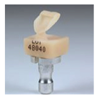
Starting Milling STEP 1: Attaching a Workpiece to the Adapter The mounting method differs depending on the workpiece type and size. P. 24 «For Disk Workpieces» » P. 27 «For Pin-type Workpieces» » Workpieces can be attached to any adapter. Point Use the included adapter rack to hold the adapters.
-
Page 25
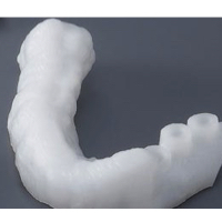
Starting Milling Remove the adapter cap. Turn the adapter cap in the direction of the arrows to remove it. Adapter cap Set the disk workpiece into the adapter base. Disk workpiece Adapter base Chapter 2 Milling… -
Page 26
Starting Milling Attach the adapter cap. Orient the adapter cap removed in step as shown in the following figure. Align the notched part on the right side. Turn the adapter cap in the direction indicated by the arrows to attach it to the screws. Chapter 2 Milling… -
Page 27
Starting Milling Use a torque screwdriver to tighten the screws in the positions shown in the figure. (4 locations) Tighten the screws until they click. CAUTION To prevent workpiece damage, tighten the screws in order across the diagonals. Attach the adapter to the machine. -
Page 28
Starting Milling Remove the adapter cap. Turn the adapter cap in the direction of the arrows to remove it. Mount the pin‑type workpiece adapter on the adapter base. Orient the pin-type workpiece adapter as shown in the following figure, and then mount this adapter on the adapter base. -
Page 29
Starting Milling Turn over the assembly prepared in step , and then align it with the positions shown in the figure. Align the recessed portion with the protrusion. Check whether the pin‑type workpiece adapter has been mounted on the adapter base without any gaps. -
Page 30
Starting Milling Turn the adapter cap in the direction indicated by the arrows to attach it to the screws. Use a torque screwdriver to tighten the screws in the positions shown in the figure. (4 locations) Tighten the screws until they click. Also, to secure the adapter evenly, after tightening the screw in one location, tighten the screw that is oriented diagonally across from it. -
Page 31
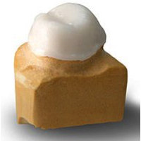
Starting Milling Mount the workpiece on the pin‑type workpiece adapter. Mounting layout examples The figure shows examples of the maximum number of workpieces that can be attached according to size. It also shows the layouts of these workpieces. Workpiece sizes are limited by the number of workpieces mounted in the machine, and the number of mountable workpieces is limited by the size of the workpieces mounted in the machine. -
Page 32
Starting Milling Use a torque screwdriver to loosen the screws holding the pin‑type workpiece in position. MEMO Use the included spare screws when a screw is lost or worn. Mount the pin‑type workpiece on the pin‑type workpiece adapter. Make sure the recessed portion of the pin-type workpiece is oriented downward, align the protrusion of the pin-type workpiece adapter with this recessed portion, and then insert the workpiece all the way in. -
Page 33: Step 2: Attaching The Adapter To The Machine
Starting Milling STEP 2: Attaching the Adapter to the Machine For Pin‑type Workpieces Procedure Switch on the machine’s power switch. P. 21 «Switching the Power On» » Once initialization completes, open the front cover. Orient the parts as shown in the figure, and then insert the adapter into the clamp. …
-
Page 34
Starting Milling Point If it is difficult to turn the knobs by hand, use the included wrench (for clamps). Lightly tug on the adapter to check that it does not come loose. Close the front cover. For Disk Workpieces Procedure … -
Page 35
Starting Milling Orient the parts as shown in the figure, and then insert the adapter into the clamp. Secure the adapter. As shown in the figure, turn the fixing knobs (in two locations) in the directions of the arrows while pressing in on the adapter. -
Page 36: Step 3: Loading The Milling Bur
Starting Milling Lightly tug on the adapter to check that it does not come loose. Close the front cover. STEP 3: Loading the Milling Bur Required Items Milling bur Milling bur holder Hexagonal Milling bur Mounting screw positioner screwdriver Procedure …
-
Page 37
Starting Milling Slide the milling bur through the milling bur holder, and determine the proper position. Insert the milling bur as shown in the figure and make sure that both ends are within the areas of the milling bur posi- tioner holes. -
Page 38: Step 4: Loading The Cleaning Tool
Starting Milling STEP 4: Loading the Cleaning Tool If you are not using the cleaning tool, proceed to the next step. Materials for Which the Cleaning Tool Is Effective Zirconia, composite resin, and CoCr sintered metal Required Items Milling bur Cleaning tool Mounting screw Hexagonal screwdriver…
-
Page 39
If the bristles of the cleaning tool spread out, the cleaning tool will not be as effective in removing the milling waste. If the bristles have spread out, replace the cleaning tool with a new one. Contact your authorized DGSHAPE Corporation dealer or visit our website (http://www.dgshape.com/) to purchase items. -
Page 40: Step 5: Checking The Regulator Settings
STEP 6: Outputting Milling Data and Starting Milling * You can also use commercial CAM software to output milling data. For information on compatible CAM software, contact your authorized DGSHAPE Corporation dealer or visit our website (http://www.dgshape.com/). WARNING Be sure to turn on the dust collector.
-
Page 41
Starting Milling Procedure Check the settings of the milling data. P. 22 «CAM Settings Necessary for Milling» » Open the [Output a file] dialog box. In the top window of VPanel, select the machine to operate. When multiple machines are connected, click under MACHINE STATUS to switch between machines. -
Page 42
Starting Milling Click [OK]. The output milling data is displayed in the JOB LIST of the top window, and then milling starts. A sound will be emitted when milling has finished. CAUTION Do not open the front cover during milling. To ensure safety, opening the front cover while milling is in progress will cause the machine to make an emergency stop. -
Page 43: Step 7: Removing The Adapter From The Machine
Starting Milling STEP 7: Removing the Adapter from the Machine WARNING Do not pull the adapter with excessive force when removing it. Doing so may result in injury arising from your hand or arm hitting something. Procedure Check that milling is finished. …
-
Page 44: Aborting Output
Starting Milling Aborting Output Procedure In the top window of VPanel, select the machine for which output will be aborted. Click The message shown in the figure will be displayed. To abort output, click [OK]. Click [Cancel] to not abort the output. Removing Milling Data in Standby from the Output List Procedure …
-
Page 45: Automatically Switching Out The Worn Milling Bur (Intelligent Tool Control)
Starting Milling Automatically Switching Out the Worn Milling Bur (Intelligent Tool Control) During milling, the milling bur wears out and may need to be replaced. If you want to have the worn milling bur switched out automatically during milling, use Intelligent Tool Control. Intelligent Tool Control is a function for consecutively using three milling burs that are all the same type.
-
Page 46: Chapter 3 Maintenance
Chapter 3 Maintenance Maintenance Precautions ………………..47 Maintenance Precautions ……………………. 47 Daily Maintenance ………………….48 Cleaning after Milling Finishes ………………….. 48 Cleaning the Milling Bur/Adapter ………………….49 Care and Storage of Detection Pin and Automatic Correction Jig ……….49 Periodic Maintenance …………………50 Situations Requiring Maintenance ………………….
-
Page 47: Maintenance Precautions
Maintenance Precautions Maintenance Precautions WARNING Never use a pneumatic blower. This machine is not compatible with pneumatic blowers. Milling waste may get inside the machine and cause fire or electrical shock. WARNING Never use a solvent such as gasoline, alcohol, or thinner to perform cleaning. Doing so may result in fire.
-
Page 48: Daily Maintenance
When the machine is in the standby state, opening the front cover and pressing the operation button will turn on the dust collector. (For dust collectors with a linking function and connected to the expansion port with a linking cable.) For details on the dust collector, see the DWX-52D «Setup Guide.» Procedure …
-
Page 49: Cleaning The Milling Bur/Adapter
Daily Maintenance Cleaning the Milling Bur/Adapter Use the included cloth for care to wipe off any dirt from the portion indicated in the figure. Part to be wiped Care and Storage of Detection Pin and Automatic Correction Jig For automatic correction, use the detection pin and the automatic correction jig. The presence of rust, scratches, or grime on the detection pin or the automatic correction jig makes accurate detection impossible, which in turn may make it impossible to perform milling as intended and may even damage the machine.
-
Page 50: Periodic Maintenance
Periodic Maintenance Situations Requiring Maintenance When installing the machine P. 52 «Spindle Run-in (Warm-up)» P. 53 «Correcting the Milling Machine» When replacing the spindle unit When the machine has not been used for a prolonged period P. 52 «Spindle Run-in (Warm-up)» Before milling on days when the ambient temperature is low When moving the machine to a different installation…
-
Page 51: Replacing Consumable Parts
Periodic Maintenance Replacing Consumable Parts Contact your authorized DGSHAPE Corporation dealer or visit our website (http://www.dgshape.com/) to purchase items. Part name Replacement time/Guideline When the working time of the spindle exceeds 2,000 hours (with slight variation depending on the work situation).
-
Page 52: Spindle Run-In (Warm-Up)
Periodic Maintenance Spindle Run‑in (Warm‑up) Spindle run-in (warm-up) may be required to stabilize the rotation of the spindle. Situations Requiring This Work When installing the machine When replacing the spindle unit When the machine has not been used for a prolonged period …
-
Page 53: Correcting The Milling Machine
Periodic Maintenance Correcting the Milling Machine The accuracy of the milling machine may change if it is used for a long period of time or the surrounding environment changes. Performing automatic correction will correct the ATC magazine and rotary axis positions. Situations Requiring This Work •…
-
Page 54
Periodic Maintenance Use the included cloth for care to clean the automatic correction jig and the detection pin. If any dirt is present in these locations, it may not be possible to perform the correction properly. Part to be wiped Detection pin Automatic correction jig Also clean the back side and the shaft. -
Page 55
Periodic Maintenance Attach the automatic correction jig. Orient the parts as shown in the figure, and then insert the automatic correction jig into the clamp. Secure the automatic correction jig. As shown in the figure, turn the fixing knobs (in two locations) in the directions of the arrows while pressing in on the automatic correction jig. -
Page 56
Periodic Maintenance Lightly tug on the automatic correction jig to check that it does not come loose. Close the front cover. Perform automatic correction. Show VPanel. P. 5 «Displaying or Exiting VPanel» » Open the [Settings] dialog box. In the top window of VPanel, select the machine to operate. -
Page 57
Periodic Maintenance Make sure that the work dis‑ played on the screen is complete. Click [OK]. Automatic correction starts. Automatic correction is complete once the screen in the figure is displayed. Click [OK]. Chapter 3 Maintenance… -
Page 58
Periodic Maintenance Remove the detection pin and the automatic correction jig. After removing the detection pin and the automatic correction jig, clean them, and then store them in the storage compartment. P. 49 «Care and Storage of Detection Pin and Automatic Correction Jig» «… -
Page 59: Retightening The Collet
Periodic Maintenance Retightening the Collet Continuous milling will cause the collet to become loose, making it easy for the milling bur to come off. Periodically retighten the collet. Recommended Interval for This Work • Once a month, or when the total work time of the spindle exceeds 200 hours (with slight variation depending on the work situation).
-
Page 60
Periodic Maintenance When the screen shown in the image on the left is displayed, click [OK]. The spindle unit will move, which will open the collet. When the screen shown in the image on the left is dis‑ played, click [OK]. -
Page 61
Periodic Maintenance Tighten the collet with the wrench while holding the detection pin. MEMO Tightening is sufficient once the wrench and the tip of the spindle unit (the shaded portion in the figure on the left) begin to rotate together. Remove the detection pin and the wrench. -
Page 62: Regulator Maintenance (Emptying The Drain)
Periodic Maintenance Regulator Maintenance (Emptying the Drain) The regulator is equipped with a filter that becomes filled with drainage (moisture and dust) over time. Periodically empty the drain. Situations Requiring This Work • When drainage builds up • When the bowl becomes dirty Procedure …
-
Page 63: Regulator Maintenance (Cleaning The Bowl)
Periodic Maintenance Regulator Maintenance (Cleaning the Bowl) If the inside of the bowl becomes dirty, remove and wash the bowl. Bowl Procedure WARNING Be sure to bleed off the air pressure before removing the regulator bowl. Failure to do so may result in a rupture or components flying off. WARNING Before removing or attaching the regulator and before performing maintenance, make sure that the bowl is securely attached.
-
Page 64
Periodic Maintenance Remove the regulator. Remove the bowl from the regulator. Loosen Tighten Bowl Wash the bowl using a neutral detergent. After making sure that the bowl is completely dry, retighten the bowl. Attach the regulator to the machine. Chapter 3 Maintenance… -
Page 65: Replacing The Cleaning Tool
Periodic Maintenance Replacing the Cleaning Tool Required Items Optional item Main unit accessories Milling bur Cleaning tool Mounting screw Hexagonal screwdriver holder Procedure Remove the cleaning tool tube. To prevent the bristles from being pulled off, grasp the cleaning tool tube gently and pull it down slowly. Tube …
-
Page 66: Chapter 4 Troubleshooting
Chapter 4 Troubleshooting Machine Trouble ………………….67 Initial Operations Are Not Performed or Fail ………………67 The Operation Button Does Not Respond ………………67 VPanel Does Not Recognize the Machine ………………67 No Data Is Being Output to the Machine, or the Machine Will Not Operate Even Though Data Is Being Output …………………….
-
Page 67: Machine Trouble
Machine Trouble Initial Operations Are Not Performed or Fail Keep the front cover closed during startup. For safety, Is the front cover open? the initial operations are not performed if a cover is — open when the machine starts. The milling bur attached to the spindle unit may fail to Is the milling bur caught on perform the initial operations if it is caught on the work- P.11…
-
Page 68: No Data Is Being Output To The Machine, Or The Machine Will Not Operate Even Though Data Is Being Output
Machine Trouble No Data Is Being Output to the Machine, or the Machine Will Not Operate Even Though Data Is Being Output If the front cover is open, the machine will not start mill- Is the front cover open? ing even if milling data is being received. Close all of the —…
-
Page 69: The Spindle Does Not Rotate
Machine Trouble The Spindle Does Not Rotate Is the spindle belt damaged or Check inside the maintenance cover. If the spindle belt is P.51 disconnected? damaged, replace it. The Ionizer Is Ineffective (Milling Waste Collects around the Milling Area) The ionizer (static electricity eliminator) is only effec- Is the workpiece being milled a tive with PMMA.
-
Page 70: Automatic Correction Fails
Machine Trouble Automatic Correction Fails Clean away any grime on the automatic correction jig, Is the automatic correction jig, the detection pin, and the ATC magazine. These items detection pin, or ATC magazine being dirty due to a buildup of milling waste or the like P.53 dirty? may impede correct sensor operation, making detection…
-
Page 71: Milling Quality Problems
Milling Quality Problems The Milled Surface Is Not Attractive Check the mounting condition of the workpiece. If the Is the workpiece firmly secured in workpiece is not mounted on the machine correctly, P.24 place? the workpiece may come loose during milling and may become misaligned.
-
Page 72: A Hole Opens In The Milling Results
Milling Quality Problems Recommended CAD data thickness values Unit: mm Front tooth crown Molar tooth crown 1.5 or higher 1.0 or higher 1.5 or higher 1.0 to 1.2 1.5 or higher 0.8 or higher 0.8 or higher Veneer Onlay Inlay 1.5 or higher 1.0 or higher 1.0 or higher…
-
Page 73: Installation Problems
Log on to Windows as the computer’s administrator (or as an «Administrators» account). Insert the DGSHAPE Software Package CD into the computer’s CD drive. When the automatic playback window appears, click [Run menu.exe]. If a [User Account Control] window appears, click [Allow] or [Yes], and then continue with the installation.
-
Page 74
Installation Problems Follow the on‑screen instructions to proceed with the installation. When the installation finishes, click on the setup menu, and then remove the DGSHAPE Software Package CD. Turn on the power to the machine. Connect the machine to the computer using the USB cable. -
Page 75: Installing The Software And The Electronic-Format Manuals Separately
Log on to Windows as the computer’s administrator (or as an «Administrators» account). Insert the DGSHAPE Software Package CD into the computer’s CD drive. When the automatic playback window appears, click [Run menu.exe]. If a [User Account Control] window appears, click [Allow] or [Yes], and then continue with the installation.
-
Page 76: Driver Installation Is Impossible
Installation Problems Driver Installation Is Impossible If installation quits partway through or if VPanel does not recognize the machine, the driver may not have been installed correctly. In such cases, perform the following procedures. (If procedure A does not solve your problem, perform procedure B.) Windows 10 and 8.1 (Procedure A) 1.
-
Page 77
Installation Problems 7. When the message «Troubleshooting has completed» is displayed, click [Close the troubleshooter]. If the printer icon for the machine you are using is displayed under «Printers,» the driver has been successfully installed. If this does not solve the problem, perform the procedure under «Windows 7 (Procedure B).» Windows 7 (Procedure B) 1. -
Page 78: Uninstalling The Driver
D: DriversWINX86 (32-bit versions) If you’re not using the DGSHAPE Software Package CD, go to the DGSHAPE Corporation website (http://www.dgshape.com/) and download the driver for the machine you want to remove, and then specify the folder where you want to extract the downloaded file.
-
Page 79: Uninstalling Vpanel
D: DriversWINX86 (32-bit versions) If you’re not using the DGSHAPE Software Package CD, go to the DGSHAPE Corporation website (http://www.dgshape.com/) and download the driver for the machine you want to remove, and then specify the folder where you want to extract the downloaded file.
-
Page 80: Responding To Error Messages
This section describes the error messages that may appear in VPanel and how to take action to remedy the problem. If the action described here does not correct the problem or if an error message not described here appears, contact your authorized DGSHAPE Corporation dealer.
-
Page 81
Responding to Error Messages Error number Message Situation/Error Cause Action 1. Press and hold the operation button on the built- The milling bur might be in panel to clear the error. broken. 2. If the milling bur is broken, replace it with a new one. -
Page 82
Turn off the power and contact your authorized 102D‑0000 or the spindle unit may be be turned. DGSHAPE Corporation dealer. defective. Make sure the dust collector The dust collector is Turn the dust collector on, and then check the dust 1030‑0000… -
Page 83
Download the latest versions of VPanel and the The versions of VPanel and machine’s firmware from the DGSHAPE Corporation the machine’s firmware may website (http://www.dgshape.com/), and then not match. install these versions. -
Page 84
R2-180606 FA01275…

![]()
TOP Dental DWX-52D
DWX-52D
Dental
Software
Manuals
- Optional Items
- CA-DK1 CA-DK2 CA-MK1 MC-BDS ZC-4D ZC-52D ZMA2-52D ZS-4D ZS-52D ZSB-170/140 ZSB-180
Document added to My List
Document deleted from My List
![]()
-
Log in
-
Join
Watch in our app
Open in app
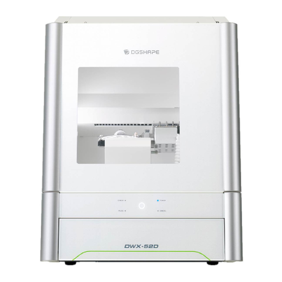
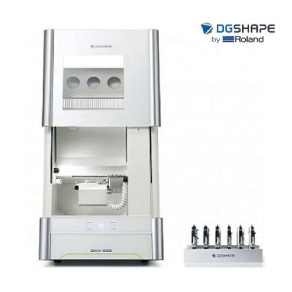
Фрезерный станок от компании Roland — это надежное зуботехническое фрезерное оборудование, которое прослужит вам на долгие годы, компактный и функциональный. Быстрая замена шпинделя без вызова инженера. все фрезеры Roland производятся в Японии.
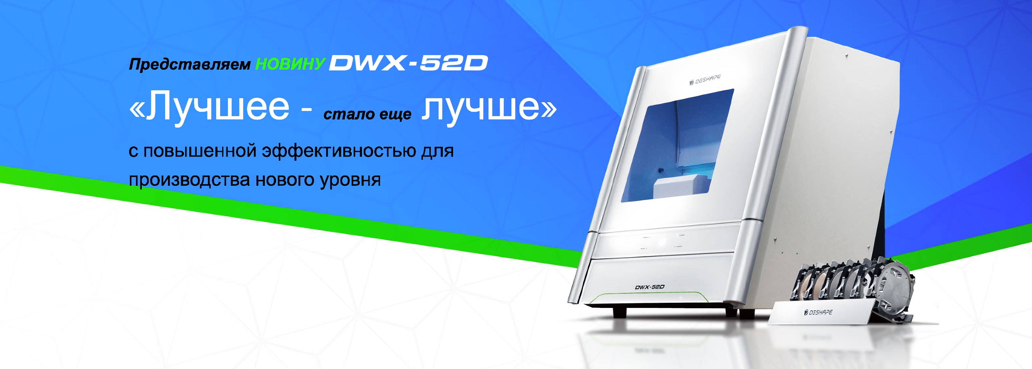
Преимущество модели Roland DWX 52D
Новая система Snap-In Clamp System для быстрой замены диска, включает в себя шесть адаптеров для материалов и обеспечивает безопасную установку c минимизации повреждение диска. Кроме того, у ДВХ-52Д есть встроенные ящики для хранения и встроенная стойка для дисков, обеспечивающая высокоорганизованное и эффективное рабочее пространство.
- Обеспечивает непрерывное фрезерование с помощью 15-и фрез (ATC)
- Автоматическое регулирования давления воздуха,
- Другие улучшенные функции включают автоматическую сборку пыли при открытии передней крышки, чтобы удалить пыль с поверхности лаборатории и поддерживать чистую и здоровую окружающую среду
- Открытая система
- Virtual Machine Panel операторам доступна опция назначения боров в любой конфигурации
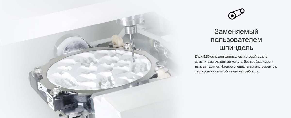
- Имеет шпиндель, который можно заменить за считанные минуты, без необходимости вызывать техника. Никаких специальных инструментов, или обучения не требуется.
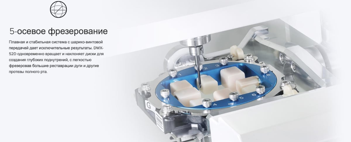
- Одновременно вращается и наклоняет диски для глубокого фрезерование больших реставраций, полная дуга!
Roland DWX 52D
DGSHAPE от Roland DG – берет за основу тридцатилетнюю надежность и инновации и сочетает их с производством нового уровня и эффективностью, чтобы удовлетворить потребности современного растущего лабораторного бизнеса.
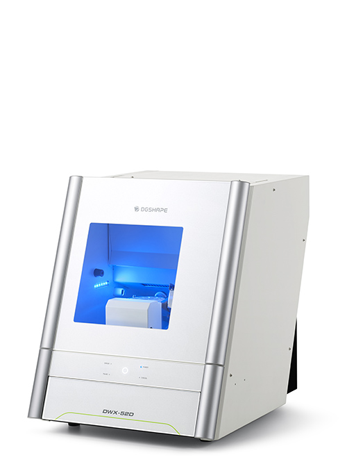
Фрезерный станок стал еще лучше.
Следующее поколение бестселлера среди фрезерных станков для циркония, воска, гипса и др. материалов сохранил в себе все, что нравится пользователям и стал еще лучше. Надежный, точный, быстрый и доступный – это новый Roland DWX-52D. Улучшенный холдер дисков, увеличенный выбор материалов для фрезеровки, новое удобное управление фрезами – все сделано для того, чтобы увеличить эффективность работы.
Чистый и точный фрезер Роланд ДВХ 52
Обеспечивает непрерывную фрезеровку с автоматической станцией на 15 инструментов и автоматической регулировке давления воздуха, которое станок меняет в зависимости от фрезеруемого материала. Также автоматическая система сбора пыли при открытии крышки обеспечит вам идеальную чистоту..
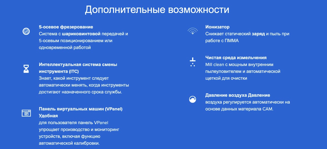
Новые возможности
Что может изготовить фрезер Roland DWX-52D ?
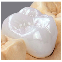
Коронки Точно фрезеруйте постоянные коронки, которые полностью покрывают зуб, создавая циркониевые и композитные протезы с точной репликацией.
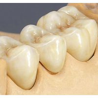
Мосты Изготавливайте замену одного или нескольких мостовидных протезов любого размера из совместимых материалов.
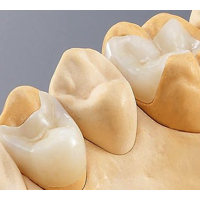
Вкладки и накладки Фрезерование непрямых вкладок (пломбы) и накладки из диоксида циркония, композитных материалов и ряда популярных материалов.
Виниры Создавайте фронтальные реставрации, такие как виниры из диоксида циркония, ПММА, композитных материалов и т. Д.
Колпачки Фрезерование различных колпачков под литье или металокерамические коронки .
Хирургические шаблоныЭффективное фрезерование каркасов протезов, балок имплантатов, шин прикуса, хирургических шаблонов и других реставрационных работ.
Абатменты Фрезерование множества абатментов и опор для частичных протезов, включая гибридные абатменты с титановой основой, клеевыми и т. Д.
Сравнение фрезерных станоков от Roland DGSHAPE
| ROLAND DWX 50D
|
ROLAND DWX 50DCI
|
|
| Обрабатываемый материал | Цирконий, воск, ПММА, композитная смола, ПЭЭК, гипс, | Цирконий, воск, ПММА, композитная смола, ПЭЭК, гипс, |
|---|---|---|
| Форма загружаемой заготовки мм | Ø 98,5 В 10-60 | Ø 98,5 В 10-60 |
| Тип Pin, мм | 6 | 6 |
| Скорость работы, мм/мин | 6–1800 | 6–1800 |
| Тип шпинделя | Бесщеточный | Бесщеточный |
| Скорость вращения шпинделя об./мин | 6 000–30 000 | 6 000–30 000 |
| Угол Ось XYZ | A: ±360°, В: ±30° | A: ±360°, В: ±30° |
| Количество инструментов, мм | 15 | 15 |
| Размеры инструментов, мм | 4, длина: 40–55 мм | 4, длина: 40–55 мм |
| давление сжатого воздуха МПа | 0,02–0,2 | 0,02–0,2 |
| Интерфейс | USB | USB |
| Питание В ± | 100-240 | 100-240 |
| Потребляемая мощность | 200 Вт | 200 Вт |
| Размеры Ш.Г.В мм | 495 x 660 x 600 | 880 x 660 x 600 |
| Гарантия | 1 год | 1 год |

Комплект поставки Roland DWX 52D
- Сетевой шнур,
- Кабель USB,
- Руководство,
- CD-ROM с ПО,
- Калибровочный штифт,
- Шестигранная отвертка,
- Шестигранный ключ,
- Колпачки (S и L),
- Отвертка
- Штифт
- Ключ
- Зажим для блочных заготовок,
- Держатель для инструментов,
- Приспособление для позиционирования инструмента,
- Рукав для сбора пыли,
- Регулятор,
- Поддон для пыли
Roland DWX 52D фрезерный станок DGSHAPE от Roland (Япония)
Roland DWX 52D фрезерный станок и другое стоматологическое оборудование доступные по низким ценам.
Купите в Москве по низким ценам у официального дилера. Подробные
характеристики, инструкции и доставка по всей России. Купите
оборудование, как «Roland DWX 52D», в магазине sigmadent, узнать наличие товара по
телефону. Мы можем доставить ваш товар бесплатно по Москве, а также
отправить в Екатеринбург, Краснодар, Нижний Новгород, Новосибирск,
Пермь, Ростов-на-Дону, Самара,Санкт-Петербург, Уфа, Архангельск,
Астрахань, Барнаул, Белгород,Брянск, Владивосток, Волгоград, Воронеж,
Иваново, Ижевск, Иркутск, Йошкар-Ола, Казань, Калининград, Калуга,
Кемерово, Красноярск, Курган, Курск, Липецк, Магнитогорск, Мегион,
Мурманск, Набережные Челны, Омск, Орел, Оренбург, Пенза, Псков, Рязань,
Саратов, Смоленск, Сочи, Сургут, Тамбов, Тверь, Томск, Тула, Тюмень,
Улан-Удэ, Хабаровск, Ханты-Мансийск, Чита, Якутск, Ярославль. регион
России транспортерной компании Деловые линии, ПЭК, СДЭК. для получение
самовывозом просьба уточнить у менеджера дату и время. получить товар в
Москве удобным для Вас способом, для этого ознакомьтесь с информацией о
доставке и самовывозе.
Теги:
roland-dwx-52d,
фрезерные,
станки,
cad/cam,
DWX52,
Роланд ДВХ 52
Мы доставляем заказы по всей территории России и СНГ.
Сроки
доставки заказа зависят от наличия товаров на складе. Если в момент
оформления заказа все выбранные товары есть в наличии, то мы доставим
заказ в течение 1 – 2 дня, в зависимости от удаленности Вашего
региона. Если заказываемый товар отсутствует на складе, то максимальный
срок доставки заказа может составить 8 недель. Но мы стараемся
доставлять заказы клиентам как можно быстрее, и 90% заказов клиентов
отправляются в течение первых 3 недель. В случае, если часть товаров из
Вашего заказа через 3 недели не поступила на склад, мы отправим все
имеющиеся в наличии товары, а затем за наш счет дошлем Вам оставшуюся
часть заказа.
Способы оплаты:
- Оплата при получении
- Онлайн-оплата картой
- Оплата в терминале
- Безналичный расчет
A Hole Opens in the Milling Results
Attaching a Workpiece to the Adapter
Attaching a Workpiece to the Adapter
Automatic Correction Fails
Any issues with heavy usage?
HELP!! I can’t find the driver I need for my Roland!
Chipping Occurs (Edges of Milling Products Become Chipped)
Compressed Air Does Not Come Out
Correcting the Milling Machine
The cut path is being clipped on one side of the print
With Roland limited warranties, you get not only extensive coverage of your device, but the best service and support in the industry. All products come standard with the manufacturers warranty outlined below, with upgrade options available on many products.
Detection Pin Maintenance
DGSHAPE Corporation Software License Agreement
The New Insights from DGSHAPE
DGSHAPE Insights is the web-based evolution of DWINDEX2, delivering mobile, virtual CAD/CAM management for your milling device. Available as a free application in DGSHAPE CLOUD. Insights build upon the features of DWINDEX2 with improved data graphics and a new UX/UI. DWX customers can manage their milling centers from anywhere, anytime, through their mobile devices or PC’s.
Process describing how to maintain the Disc Changer Chamber
Process describing how to maintain the Disc Changer Chamber
DWX-52D Daily Maintenance
DWX-52D Spindle Unit Replacement dgs
DWX-52DCi error “104F-202” T-axis shift occurs
Edges of Milling Products Become Chipped
Error «101D-0010» The cleaning tool cannot be released.
Error “104F-202” T-axis shift occurs
Error Code «****_****» An unknown error occurred.
Error Code «1000-XXXX» The % limit switch was not found.
Error Code «1006-02» The % axis position has been shifted.
Error Code «1017-0000» The front cover was opened.
Error Code «1017-0001» The front cover or the magazine cover was opened.
Error Code «101C-0000» The milling bur sensor was not found.
Error Code «101D-****» The milling bur cannot be released.
Error Code «101E-****» The % milling bur might be broken.
Error Code «101F-****» The % milling bur chucking has slipped out.
Error Code «1020/1021-****» The % milling bur is too long./The % milling bur is too short.
Error Code «1022-****» The % milling bur was not found.
Error Code «1022-0010» The cleaning tool was not found.
Error Code «1023-0000 to 1028-0000» Milling data error.
Error Code «1029-0000» The spindle experienced an overload.
Error Code «102A-0000» The spindle experienced overcurrent.
Error Code «102B-0000» The spindle motor temperature is too high.
Error Code «102D-0000» The spindle cannot be turned.
Error Code «102E-0000» The spindle has collided with the rotary axis unit
Error Code «102E-0001» The changer has collided with the adapter.
Error Code «1030-0000» The dust collector is not working.
Error Code «103B-0000» The automatic correction is not yet finished.
Error Code «103D-0000» Milling data error. The milling bur cannot reach the milling position.
Error Code «1047-****» The machine’s internal memory cannot be accessed.
Error Code «1049-****» The adapter with ID number % cannot be released.
Error Code «104A-****»The adapter with ID number % could not be grasped.
Error Code «104B-00**» The adapter with ID number % was not found.
Error Code «104D-00**» An adapter with the same ID was found.
Error Code «104E-****» The % limit switch was not found.
Error Code «104F-02**» The % axis position has been shifted.
Error Code «1050-****» The operation to read a bar code failed.
Looking into production yields
Looking for general information on tool life
What steps should I take prior to running a milling job?
HELP!! I can’t find a Windows 7 driver for my machine!!
HELP!! I can’t find a Windows8 driver for my machine!!
Does it require a step in the disc?
Initial Operations Are Not Performed or Fail
Any issues using composite resin blocks?
Message [ERROR OCCUR] 1024-0000 Milling data error
MillBox — How do I backup MillBox Job files for expedited support?
MillBox — Security Software / Anti-Virus Exclusions
DGSHAPE CLOUD enables comprehensive, mobile management for your milling center. Using its suite of world class applications, you can remotely monitor and support your CAD/CAM milling devices, compare periodized production data, and oversee your milling center.
No Data Is Being Output to the Machine, or the Machine Will Not Operate Even Though Data Is Being Output
No Data Is Being Output to the Machine, or the Machine Will Not Operate Even Though Data Is Being Output
Tech Support Terms and Conditions
Information about my legacy product
We highly recommend performing periodic maintenance cycles and procedures. Here is a quick topic that is not included when diagnosing milling issues. For this example, I chose the DWX-52D to explain the points of inspection on the Rotary Axis Unit.
Instructions on how to set up a webcam using VPanel
Can I use either of these cleaning cartridges interchangeably?
T-axis position has shifted Message Work Around
Tech Support Terms and Conditions
The Cleaning Tool Is Not Effective
The Computer Shuts Down When Connecting Multiple Machines
The Dimensions of the Milling Results Do Not Match
The Ionizer Is Ineffective (Milling Waste Collects around the Milling Area)
The Ionizer Is Ineffective (Milling Waste Collects around the Milling Area)
The Milled Surface Is Not Attractive
The Milling Bur Management Information Was Lost
The Operation Button Does Not Respond
The Operation Button Does Not Respond
The Spindle Does Not Rotate
The Spindle Does Not Rotate
There Is a Line of Level Difference in the Milling Results
There Is a Line of Level Difference in the Milling Results
The following procedure will outline the process of how to clean and ensure the tool sensor is working properly
VPanel Does Not Recognize the Machine
VPanel for DWX User’s Manual [ 2021-05-14, R1 ]
Different ways to arrange the VPanel layout and resetting the application back to default
Keeping VPanel up to the latest version is very important and we just made it easier. Take a look at the following video and find out more.
When outputting a design to your engraver or milling machine, the software needs to be able to translate commands to the device. These commands tell the machine how fast to mill, at what revolutions per minute (RPM), and where to mill in 3D space. This is what makes up a toolpath. A Strategy is a combination of tool movements, material properties, software algorithms, and tool characteristics.
Can it hold both a disc and a pin type block?
What are the specifications of the compressor?
Interested in the dust collector specifications
Do I really need to purchase this accessory item?