- Manuals
- Brands
- Rosslare Manuals
- Control Unit
- AC Series
- Advanced installation and programming manual
-
Bookmarks
Quick Links
AC-x32 Series
Standalone Access Control Units
Installation and Programming Manual
AC-B32
AC-C32
AC-D32
Related Manuals for Rosslare AC Series
Summary of Contents for Rosslare AC Series
-
Page 1
AC-x32 Series Standalone Access Control Units Installation and Programming Manual AC-B32 AC-C32 AC-D32… -
Page 2
ROSSLARE. ROSSLARE reserves the right to revise and change this document at any time, without being obliged to announce such revisions or changes beforehand or after the fact. -
Page 3
Table of Contents Table of Contents Introduction …………..8 Reader/Controller Types…………8 Equipment …………….8 Additional Equipment ………….. 9 Technical Specifications ……….10 Installation …………..12 Mounting …………….12 Wiring ……………… 14 3.2.1 AC-B32 ………………14 3.2.2 AC-C32 ………………15 3.2.3 AC-D32 ……………… -
Page 4
Table of Contents BL-D40 External Sounder …………21 Programming …………23 Entering Programming Mode ……….24 Exiting Programming Mode ……….. 24 Changing Open Code 1…………25 Changing Open Code 2…………25 Changing the Programming Code ………. 26 Changing the Normal/Secure Code ……..27 Changing the Normal/Bypass Code and Door Chime Settings .. -
Page 5
List of Figures List of Figures Figure 1: AC-B32 – Mounting Holes and Terminal Blocks …….. 12 Figure 2: AC-C32 – Mounting Holes and Terminal Blocks …….. 13 Figure 3: AC-D32 – Mounting Holes and Terminal Blocks …….. 13 Figure 4: AC-B32 – Wiring the Lock Strike Relay and REX …….. 14 Figure 5: AC-B32 –… -
Page 6
List of Tables List of Tables Table 1: Programming Menu …………….23 AC-x32 Series Installation and Programming Manual… -
Page 7
ROSSLARE exclusive warranty and liability is limited to the warranty and liability statement provided in an appendix at the end of this document. … -
Page 8
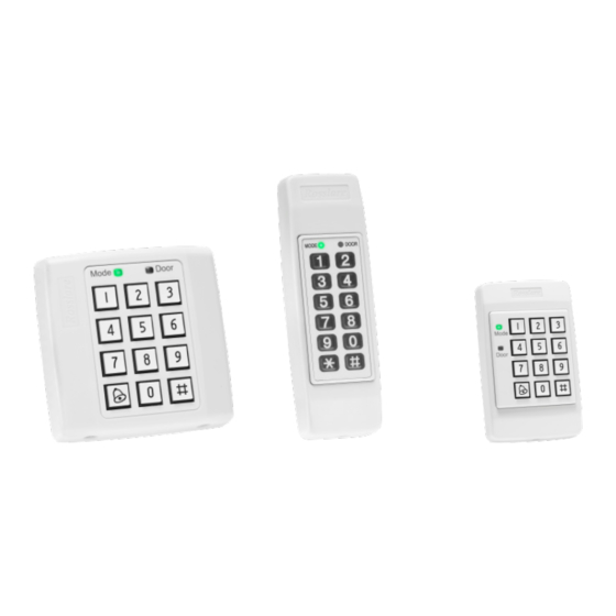
Introduction Introduction The AC-x32 is a series of indoor standalone controllers. The units accept up to 500 users and allow entry via a personal identification number (PIN) or by presenting a proximity card. Reader/Controller Types The six types of units described in this manual are: Keypad Type PIN Proximity AC-B32 3X4 Standard… -
Page 9
Request to Exit (REX) button – Normally Open Type; switch is closed when pressed. BL-D40 External Sounder (optional) – Provides siren, bell, and chime functions to the controller Other Rosslare accessories can be found at Rosslare’s website: http://www.rosslaresecurity.com AC-x32 Series Installation and Programming Manual… -
Page 10
• Read Range: 90 mm (3.5 in.)* • Modulation: ASK at 125 kHz • Compatible cards: All 26-Bit EM cards Measured using a Rosslare proximity card or equivalent. Range also depends on electrical environment and proximity to metal. AC-x32 Series Installation and Programming Manual… -
Page 11
Technical Specifications Environmental Characteristics Operating Temp. Range -31°C to 63°C (-25°F to 145°F ) Operating Humidity Range 0 to 95% (non-condensing) Physical Characteristics Dimensions AC-B32: 92 x 92 x 24 mm (3.6 x 3.6 x 0.9 in.) (Length x Width x Depth) AC-C32: 130 x 42 x 18 mm (5.1 x 1.7 x 0.7 in.) AC-D32: 122 x 75 x 24 mm… -
Page 12
Installation Installation Installation of an RFID reader adjacent to metallic surfaces might alter the reader’s specifications. To diminish this interference, use a plastic spacer when mounting the reader. Mounting Before starting, select the location to mount the controller. This location should be at shoulder height and on the same side as the door handle. -
Page 13
Installation Figure 2: AC-C32 – Mounting Holes and Terminal Blocks Figure 3: AC-D32 – Mounting Holes and Terminal Blocks 5. Wire the controller as shown in Section 3.2. 6. Screw the back plate into the surface. Ensure the screws are the size specified on the installation template. -
Page 14
Installation Wiring Typical wiring diagrams for the various units are shown in the following subsections. 3.2.1 AC-B32 Figure 4: AC-B32 – Wiring the Lock Strike Relay and REX Figure 5: AC-B32 – Wiring the BL-D40 External Sounder AC-x32 Series Installation and Programming Manual… -
Page 15
Installation 3.2.2 AC-C32 Figure 6: AC-C32 – Wiring the Lock Strike Relay and REX Figure 7: AC-C32 – Wiring the BL-D40 External Sounder AC-x32 Series Installation and Programming Manual… -
Page 16
Installation 3.2.3 AC-D32 Figure 8: AC-D32 – Wiring the Lock Strike Relay and REX Figure 9: AC-D32 – Wiring the BL-D40 External Sounder AC-x32 Series Installation and Programming Manual… -
Page 17
Operation Operation User Levels The controller accepts up to 500 users and provides entry via the use of proximity cards and/or PIN codes. Each user is provided with two code memory slots: Memory Slot 1 (Primary Code) and Memory Slot 2 (Secondary Code). -
Page 18
Operation Modes of Operation The controllers have three modes of operation: 4.2.1 Normal Mode Mode Door The Mode LED is green Green Normal Mode is the default mode. In Normal mode, the door is locked until a Primary code is presented to the controller. Special codes such as “Open Code”… -
Page 19
Operation Changing the Modes of Operation 4.3.1 Changing from Normal to Secure Mode The default factory setting for the Normal/Secure Code is 3838. To change from Normal to Secure mode: 1. Enter the 4-digit Normal/Secure code. The Mode LED flashes red. Mode Door 2. -
Page 20
Operation 4.3.3 Changing from Normal to Bypass Mode By default, there is no Normal/Bypass code. The Normal/Bypass code must first be programmed to use this function (see Section 5.6 to create/modify the Normal/Bypass Code). To change from Normal to By pass mode: 1. -
Page 21
The BL-D40 External Sounder is compatible with the AC-x32 series of standalone controllers. (For a more up-to-date list of compatible products, check the Rosslare website at www.rosslaresecurity.com.) It is designed to operate indoors and is installed within the premises to be secured. -
Page 22
The controller can also program the length of the siren in the BL-D40. The controller communicates with the BL-D40 using a coded proprietary Rosslare communications protocol. This provides a more secure link between the controller and the BL-D40. If the BLD40 receives any unrecognized codes on its communication line, or… -
Page 23
Programming Programming Programming is done solely via the unit’s keypad driven Programming Menu System. To reach the Programming Menu System, the unit must first be put into Programming mode (see Section 5.1). During the manufacturing process, certain codes and settings are pre- programmed. -
Page 24
Programming Entering Programming Mode The controller must be in Normal mode to enter the Programming mode. The factory default Programming code is 1234. If a Programming code is not entered within five seconds, the unit returns to Normal mode. To enter Programming mode: 1. -
Page 25
Programming Changing Open Code 1 Open Code 1 is mainly used as a method to quickly test the Lock Strike Relay during installation. The default factory setting for Open Code 1 is 2580. When the first user is added to the controller, the default Open Code 1 is automatically deleted, and is ready for a new Open Code 1 to be re-entered. -
Page 26
Programming To change the Open Code 2: Mode Door 1. Enter Programming mode. Green 2. Press 2 to enter Menu 2. Mode Door The Mode LED turns orange. Orange Green 3. Enter the new 4-digit Open Code 2 code. Mode Door Three beeps are emitted. -
Page 27
Programming Changing the Normal/Secure Code When the Auxiliary Mode is 1, 2, 3, or 4, the Auxiliary Input takes priority over the Normal/Secure Code. To change the Normal/ Secure code: Mode Door 1. Enter Programming mode. Green 2. Press 4 to enter Menu 4. The Mode LED flashes red. -
Page 28
Programming 3. There are four different ways to program the Normal/Bypass code and door chime: Disable both Bypass Code and the door chime. Enter the code 0000. Disable Bypass Code and enable the door chime. Enter the code 0001. … -
Page 29
Programming Construct the 4-digit code using the following instructions: First Digit For Fail Secure Operation, the first digit should be 0. For Fail Safe Operation the first digit should be 1. Second Digit Siren time in minutes (1-9, 0-disabled) … -
Page 30
Programming 5.9.2 Secondary Codes Secondary codes can only be enrolled to a user slot that already has a Primary Code enrolled, but no Secondary code. Secondary Codes do not have to be unique, meaning that multiple users can all hold the same Secondary code. … -
Page 31
Programming 3. Perform one of the following: a. Enter a 3-digit User Slot number between 001 and 500 to indicate the user to whom you want to enroll a Primary or Secondary code. For example, the User Slot 003 represents User #3. Mode Door If the selected slot has no Primary… -
Page 32
Programming 5.9.5 Enrolling Secondary Codes Using the Code Search Method The Code Search feature enables you to quickly enroll a Secondary Code to a user who already has a Primary Code. To enroll secondary codes using the Code Search method: Mode Door 1. -
Page 33
Programming 5.10 Deleting Primary and Secondary Codes There are two methods to delete Primary and Secondary codes: the Standard Method and the Code Search method. When deleting a user slot, both the Primary code and the Secondary code are erased. It is recommended that a record be kept of added and deleted users so that it is easier to keep track of which user slots are empty and which user slots are not. -
Page 34
Programming 4. Enter your 4-digit Programming code to confirm the deletion. If the Programming code is valid, three beeps are emitted and the unit returns to Normal mode. If the Programming code is invalid, a long beep is emitted and the unit returns to Normal mode. -
Page 35
Programming 4. Enter the 4-digit PIN code of the Primary Code belonging to the user you want to delete. Mode Door The Mode LED flashes red. Red Orange 5. Enter your Programming code to confirm the deletion. If the Programming code is valid, three beeps are emitted and the unit returns to Normal mode. -
Page 36
Programming 5.12 Replacing a Lost Programming Code To be able to replace a lost programming code, the controller must be in Normal mode. Before proceeding, verify that the Mode LED is green. 1. Remove power from the unit. 2. Press the REX button. 3. -
Page 37
The full ROSSLARE Limited Warranty Statement is available in the Quick Links section on the ROSSLARE website at www.rosslaresecurity.com. Rosslare considers any use of this product as agreement to the Warranty Terms even if you do not review them. AC-x32 Series Installation and Programming Manual… -
Page 38
Tel: +86-755-8610 6842 Fax: +86-755-8610 6101 Rosslare Security Products, Inc. support.cn@rosslaresecurity.com Southlake, TX, USA India Toll Free: +1-866-632-1101 Local: +1-817-305-0006 Rosslare Electronics India Pvt Ltd. Fax: +1-817-305-0069 Tel/Fax: +91-20-40147830 support.na@rosslaresecurity.com Mobile: +91-9975768824 Europe sales.in@rosslaresecurity.com Rosslare Israel Ltd. Rosh HaAyin, Israel…
ROSSLAR E
www.rosslare.com.hk
ROSSLARE
INSTRUCTION MANUAL
Mode
1
2 3
4 5 6
Door
7 8 9
0
#
AC-D32
STAND-ALONE
ACCESS CONTROL UNIT
08/01
Contents
INTRODUCTION
Technical Specifications
Key Features
INSTALLATION
Mounting the AC-D32 Controller
Wiring Diagrams
FEATURES AND CONCEPTS
Normal, Secure, & Master Users
Modes Of Operation
Changing the Modes of Operation
Request To Exit (REX) Button
Case and Back Tamper
BL-D40 External Sounder
PROGRAMMING THE AC-D32
Entering Programming Mode
Exiting Programming Mode
1 Changing the Open Code 1
2 Changing the Open Code 2
3 Changing the Programming Code
4 Changing the Normal / Secure Code
5 Changing the Normal / Bypass Code
Door Chime Settings
6 Setting Fail Safe / Secure Operation
Setting Tamper Siren Time
Setting the Lock Strike Release Time
7 Enrolling Primary and Secondary Codes
8 Deleting Primary and Secondary Codes
0 Return to Factory Default Settings
Replacing a lost Programming Code
Replacing a lost Normal / Secure Code
APPENDIX
Glossary
TECHNICAL SUPPORT
AC-D32 Page 2
22
23
26
28
20
20
22
22
16
17
17
18
18
19
20
29
29
10
11
12
14
15
16
3
4
5
6
6
8
30
33
08/01
Introduction
The AC-D32 is a proximity card and keypad access control unit.
The unit accepts up to 500 users and provides entry via the use of proximity cards and/or PIN codes.
Equipment provided
The following is provided as part of every AC-D32 package:
— AC-D32 Access Control Unit.
— Installation Kit
— Installation and Operating Instructions
Additional Equipment Required
1) Electric Lock Strike Mechanism
Fail Safe (Power to Lock) or Fail Secure (Power to Open)
2) Power Supply with Backup Battery
12 to 16V DC (From a Regulated Power Supply)
3) Request To Exit (REX) Button
Normally Open Type — Switch is closed when pressed.
4) BL-D40 External Sounder (Optional)
Provides Siren, Bell, and Chime functions to AC-D32
Other Rosslare accessories can be found at Rosslare’s
Web Site: http://www.rosslare.com.hk
AC-D32 Page 3 06/01
Technical Specification
Electrical Characteristics
Operating Voltage Range:
12 to 16V DC From a Regulated Power Supply
Maximum Input Current:
Standby: 40mA
Max: 90mA
Not including attached devices
Not including attached devices
Relay Outputs:
Lock Strike Relay
Auxiliary Relay
Inputs:
REX N.O., Dry Contact
Auxiliary Input (In / Monitor) N.C., Dry Contact in Monitor Mode
N.O., Dry Contact in Input Mode
LEDs
Two Tri-colored LEDs
Electronic, 3.5A
with built in suppressor protection
Form C, 1A
Built-In Proximity Reader
Read Range*
Modulation
Compatible Cards
3.5″ (90mm)
ASK at 125kHz
All 26-Bit EM Cards
Environmental Characteristics
Operating Temperature:
-25°F to 145°F (-31°C to 63°C)
Operating Humidity:
0 to 95% (Non-Condensing)
Mechanical Characteristics
Dimensions:
4.80″ (122mm) L x 2.95″ (75mm) W x 0.94″ (24mm) D
Weight:
0.3 lbs (130g)
*
Measured using Rosslare Proximity Card (AT-11/12) or equivalent. Range also depends on electrical environment and proximity to metal.
AC-D32 Page 4 08/01
Key Features
Here are some of the AC-D32’s key features:
!
!
!
!
!
!
Built in Proximity Card Reader (125 KHz ASK Modulation)
Built in Keypad for PIN code entry
Internal Buzzer
Comes with security screw and security screw tool
Two Status / Programming Interface LED’s
Three User Levels
(Normal User, Secure User, Master User)
!
Three Modes of Operation
!
!
!
!
!
!
!
!
!
!
(Normal Mode, Bypass Mode, Secure Mode)
«Code Search» feature makes maintaining user codes easier.
Input for Request to Exit (REX) button.
Lock Strike Electronic Relay with built-in suppressor protection.
Comes with mounting template for easier installation.
Built in Case and Back Tamper
Bell, Chime, Siren, and Strobe features available with BL-D40.
Bell, Chime, Siren, Battery Backup, Tamper Output (Open
Collector 20mA) features available with PS-X41 (Output Power
1.2A) and PS-X42 (Output Power 1.8A).
Programmable Siren Time
Programmable Lock Strike Release Time
Comes with Suppression Diode (1N4004)
AC-D32 Page 5 06/01
Installation
Mounting the AC-D32 Controller
1)
Before starting, select the location to mount the AC-D32 controller. This location should be at shoulder height and on the same side as the door handle.
2)
The AC-D32 is designed to be easily mounted to a US Gang Box.
Remove the Bezel Screw. (Use the diagram below to help you locate the Bezel Screw)
Mode LED
Door LED
Bell Button
Mode
1 2 3
4 5 6
Door
7 8 9
0 #
2 x 6 Matrix Keypad
Bezel Screw
3)
Screw the controller onto a US Gang Box through the two
Mounting Holes provided. (See diagram on the next page to help you locate the US Gang Box mounting holes)
AC-D32 Page 6 06/01
Terminal Blocks
Mounting Hole
Mode
1 2 3
4 5 6
Door
7 8 9
0 #
Mounting Hole
AC-D32
4)
Pass the wires through the exit/entry holes and attach them to the controllers terminal blocks as shown in the wiring diagrams.
(Wiring diagrams for common installations can be found on pages 10 to 12).
5)
Replace the controller’s bezel and replace the factory default screw with the security screw that is provided in the Installation
Kit. A security screw tool is also provided in the Installation Kit.
Wiring the AC-D32 Controller
A few of the typical wiring diagrams are shown on the next three pages; for other wiring diagram examples refer to the support section of the Rosslare Web Site.
http://www.rosslare.com.hk/support
AC-D32 Page 7 08/01
Wiring Diagrams
BL X/ RE
(-)
(+)
REX
REX / BL
Lock
AC-D32 Page 8 06/01 AC-D32
BL X/ RE
(-)
(+)
Page 9 06/01
Normal, Secure, & Master Users
The AC-D32 accepts up to 500 users and provides entry via the use of proximity cards and / or PIN codes. Each user is provided with two code memory slots, Memory Slot 1 (Primary Code) and
Memory Slot 2 (Secondary Code). The two memory slots can be programmed as Proximity Cards, PIN codes, or a combination of both Proximity Cards and PIN codes.
The way in which the two memory slots are programmed determines a users access level and also determines the way in which the AC-D32 grants access in its three Modes of Operation.
There are three user levels:
Normal User
A Normal User only has a Primary Code and is only granted access when the AC-D32 is in Normal or
Bypass Mode.
Secure User
A Secure User must have a Primary and Secondary
Code programmed, the two codes must not be the same. The Secure User can gain access when the
AC-D32 is in any of its three Modes of Operation. In
Normal Mode the Secure User must use their
Primary Code to gain entry. In Secure Mode the
Secure User must present both their Primary and
Secondary Codes in order to gain entry.
Master User
A Master User must have both Primary and
Secondary Codes programmed with the same
Proximity Card or PIN code. The Master User can gain access during any Mode of Operation by presenting their Proximity Card or PIN code to the controller. (The Master User is convenient but is less secure than a Secure User).
AC-D32 Page 10 06/01
Modes of Operation
The AC-D32 has 3 Modes of Operation:
1) Normal Mode
.
!
Mode LED is green
Mode
GREEN
Door
Normal Mode is the default mode. In Normal Mode the door is locked until a Primary Code is presented to the controller. Special codes such as “Open Code 1” and “Open Code 2” are active in
Normal mode. (See Page 18 for more information on Open Code
1 & Open Code 2).
2) Bypass Mode.
!
Mode LED is orange
Mode
ORANGE
Door
In Bypass Mode, access to the premises is dependent on whether the controller’s Lock Strike Relay is programmed for Fail
Safe Operation or Fail Secure Operation.
When the Lock Strike Relay is programmed for
Fail Secure Operation, the door is locked until the Door
Bell Button is pressed.
When the Lock Strike Relay is programmed for
Fail Safe Operation, the door is constantly unlocked.
Mode Door
Mode LED is red
RED
Only Secure and Master Users can access the premises during the Secured Mode.
A Secure User must enter their Primary and
Secondary Codes to gain entry. After entering their Primary
Code the Door LED will flash green for 10 seconds, during which the Secondary Code must be entered.
A Master User only needs to present their Proximity
Card or PIN code once to gain entry.
AC-D32 Page 11 06/01
Changing the Modes of Operation
Changing from Normal Mode to Secure Mode :
The default factory setting for the Normal / Secure Code is 3838
1)
Enter the 4-digit Normal / Secure
Code
2)
!
Mode LED will flash red
Press the
«#»
key to confirm the Mode change.
!
Mode LED is red
Mode
GREEN
Mode
RED
Mode
RED
Door
Door
Door
Changing from Secure Mode to Normal Mode :
The default factory setting for the Normal / Secure Code 3838
1)
Enter the 4-digit Normal / Secure
Code.
2)
!
Mode LED will flash green.
Press the
«#»
key to confirm the Mode change.
!
Mode LED will turn green.
Mode
RED
Mode
GREEN
Mode
GREEN
Door
Door
Door
Changing from Normal Mode to Bypass Mode
:
See Page 20 to create / modify the Normal / Bypass Code
1)
Enter the 4-digit Normal / Bypass
Code.
!
Mode LED will flash orange
2)
Press the
«#»
key to confirm
Mode LED will turn orange
Mode
GREEN
Mode
ORANGE
Mode
ORANGE
Door
Door
Door
Changing from Bypass Mode to Normal Mode :
See Page 20 to create/modify the Normal / Bypass Code
1)
Enter the 4-digit Normal / Bypass
Code.
!
Mode LED will flash green
Mode
ORANGE
2)
Press the
«#»
key to confirm the Mode change.
!
Mode LED will turn green
Mode
GREEN
Mode
GREEN
Door
Door
Door
AC-D32 Page 12 06/01 AC-D32 Page 13 06/01
Request to Exit (REX) Button
The REX button must be located inside the premises to be secured and is used to open the door without the use of a proximity card or
PIN code, it is usually located in a convenient location, e.g. Inside the door or at a receptionist’s desk. The function of the REX button depends on whether the Lock Strike Relay is programmed for Fail
Safe Operation or Fail Secure Operation. The door chime in the BL-
D40 does not sound when the REX button is used to open the door.
1)
Fail Secure Operation: From the moment the REX button is pressed, the door will be unlocked until the «Lock Strike Release
Time» has passed. After this time, the door will be locked even if the REX button has not been released.
2)
Fail Safe Operation: From the moment the REX button is pressed, the door will be unlocked until the REX button is released, plus the «Lock Strike Release Time». In this case the
«Lock Strike Relay» only begins its count down once the REX button has been released.
Case and Back Tamper
If the case of the controller is opened or the controller is removed from the wall, a tamper event is triggered and a coded tamper signal is sent to a BL-D40, PS-X41 Series or PS-X42 Series Power
Supply, or other compatible device.
If the BL-D40 External Sounder , PS-X41 Series or PS-X42 Series
Power Supplies receive a Tamper Event Signal, they will activate a
Siren and if available a Strobe Light. The Siren time can be easily programmed in the AC-D32 from 0 to 9 minutes.
Clearing a tamper event is done by entering a valid User or Open
Code that will open the Lock Strike Output in the current Mode of
Operation. For example, while in Secure Mode, using the Open
Code to clear tamper event will not work because the Open Code does not work in Secure Mode. However, applying a Master Code or Secure Code will clear the tamper event in Secure Mode.
AC-D32 Page 14 06/01
BL-D40 External Sounder
The BL-D40 External Sounder is compatible with the AC-X31, AC-
X32, AC-X41, and AC-X42 series Standalone Controllers (For a more up-to-date list of compatible products check the Rosslare Web
Site at www.rosslare.com.hk). It is designed to operate indoors and installed within the premises to be secured. The Sounder can be powered by 16V AC or 12 to 24V DC power supply.
The BL-D40 is capable of emitting four different types of alerts both audible and visual; Bell, Door Chime, Siren, and Strobe Light.
1)
The Bell always sounds when the controller’s doorbell button is pressed.
2)
The Door Chime can be programmed to sound whenever the controller unlocks the door (the Door Chime does not sound when the REX button is used to open the door).
3)
The Siren can be programmed to sound when the case of the controller is opened or when the controller is removed from the wall. The controller can also program the length of the Siren in the BL-D40.
The Controller communicates with the BL-D40 using a coded proprietary Rosslare communications protocol. This provides a more secure link between the Controller and the BL-D40. If the BL-
D40 receives any unrecognized codes on its communication line or communication between the controller and the BL-D40 are severed, the Strobe with flash repeatedly until the communication problem has been resolved.
AC-D32 Page 15 06/01
Programming the AC-D32
Programming the AC-D32 is done solely via the unit’s keypad driven
Programming Menu System. To reach the Programming Menu
System the AC-D32 must first be placed into Programming Mode.
See «Entering Programming Mode» on Page 17 for more information.
During the AC-D32’s manufacturing process certain codes and settings are pre-programmed. These settings are the called the
«Default Factory Settings».
The table below shows the names of all the AC-D32 Menus. It also shows of all the AY-D32’s default factory codes and settings.
Programming Menu
Factory
Settings
Menu Description
2580
0852
1234
3838
N/A
0004
Change Open Code 1
Change Open Code 2
Change Program Code
Change Normal / Secure Code
Change Normal / Bypass Code
Change Door Release Time
Enroll Proximity Cards, PIN Code or both.
Delete Proximity Cards Or PIN Code
Return to Default Factory Setting
Menu
Number
1
2
3
4
5
6
7
8
0
You will find a complete description and instructions for each of the above menu items on the following pages.
AC-D32 Page 16 06/01
Entering Programming Mode
1)
!
!
«#»
key for 2 seconds.
Mode LED will turn off
Door LED will turn red
2)
Enter your 4-digit Programming
Code.
Mode
RED
Door
1 2 3 4
If the Programming Code is valid the door LED will turn green and the AC-D32 will be in
Programming Mode.
Mode
GREEN
Door
Note:
— The AC-D32 must be in Normal Mode to enter the
Programming Mode.
— The factory default Programming Code is 1234
— If a Programming Code is not entered within 5 seconds, the AC-D32 will return to Normal Mode.
Exiting Programming Mode
1)
To exit the Programming Mode at any time:
!
!
«#»
key for 2 seconds.
You will hear 3 beeps.
The Door LED will be off
The Mode LED will turn green
Mode
GREEN
Door
This indicates that the AC-D32 has returned to Normal Mode.
2)
Wrong entries may reset the controller back to Normal Mode.
3)
While in Programming Mode if no key is pressed for 1 minute the
AC-D32 will exit programming mode and return to Normal Mode.
4)
A short press on
«#»
key may also return the system to Normal
Mode in certain Programming Modes.
AC-D32 Page 17 06/01
Changing the Open Code 1
The Open Code 1 is mainly used as a method to quickly test the
Lock Strike Relay during installation.
The Default Factory Setting for the Open Code 1 is 2580.
When the first user is added to the controller, the default Open
Code will automatically be deleted, ready for a new Open Code 1 to be re-entered.
1)
Enter Programming Mode
2)
Press
!
«1»
to enter
Menu 1
The Mode LED will turn red
3)
Enter the new 4-digit code you wish to set as Open Code 1.
Mode
Mode
RED
GREEN
Door
GREEN
Door
? ? ? ?
4)
!
!
The Door LED will turn off
The Mode LED will turn green
Mode
GREEN
Door
Note:
— Open Code 1 does not function in Secure Mode.
— Wrong entries will return the controller to Normal Mode.
— Code 0000 will erase and deactivate the Open Code.
Changing the Open Code 2
The Open Code 2 is mainly used as a method to quickly test the
Lock Strike Relay during installation.
The Default Factory Setting for the Open Code 2 is 0852.
When the first user is added to the controller, the default Open
Code will automatically be deleted, ready for a new Open Code 2 to be re-entered.
AC-D32 Page 18 08/01
1)
Enter Programming Mode
2) «2»
to enter
Menu 2
The Mode LED will turn red
3)
Enter the new 4-digit code you wish to set as Open Code 2.
4)
System returns to Normal Mode
!
You will hear three beeps
!
!
The Door LED will turn off
The Mode LED will turn green
Mode
GREEN
Door
Mode
ORANGE GREEN
Door
? ? ? ?
Mode
GREEN
Door
Note:
— Open Code 2 does not function in Secure Mode.
— Wrong entries will return the controller to Normal Mode.
— Code 0000 will erase and deactivate the Open Code.
Changing the Programming Code
1)
Enter Programming Mode
Mode Door
GREEN
2)
Press
!
«3»
to enter
Menu 3
The Mode LED will turn green.
3)
Enter the new 4-digit code you wish to set as Programming Code
Mode
GREEN GREEN
Door
? ? ? ?
4)
!
!
You will hear three beeps
The Door LED will turn off
The Mode LED will turn green
Mode
GREEN
Door
Note:
— Programming Code can not be erased, i.e. the code
0000 is not valid and will not erase the Programming
Code.
AC-D32 Page 19 06/01
Changing the Normal / Secure Code
1)
Enter Programming Mode
Mode
GREEN
Door
2)
Press
!
«4»
to enter
Menu 4
The Mode LED will flash red
3)
Enter the new 4-digit code you wish to set as Normal / Secure Code
Mode
GREEN
Door
RED
? ? ? ?
4)
!
!
System returns to Normal Mode
!
You will hear three beeps
The Door LED will turn off
The Mode LED will turn green
Mode
GREEN
Door
Note:
— When the Auxiliary Mode is 1, 2, 3, or 4 the Auxiliary
Input takes priority over the Normal / Secure Code.
Changing the Normal / Bypass Code and Door Chime Settings
The Normal / Bypass Code is also used to turn the Door Chime off and on.
1)
Enter Programming Mode
Mode
GREEN
Door
2)
Press
!
«5»
to enter
Menu 5
The Mode LED will flash orange.
Mode
ORANGE GREEN
Door
3)
Below is a list of the four different ways that the Normal / Bypass
Code and Door Chime can be programmed.
a) b) c) d)
Disable Bypass Mode — Disable Door Chime
Disable Bypass Mode — Enable Door Chime
Enable Bypass Mode — Disable Door Chime
Enable Bypass Mode — Enable Door Chime
AC-D32 Page 20 06/01
a)
Disable Bypass Code — Disable Door Chime
Enter the 4-digit code 0000
0 0 0 0 b)
Disable Bypass Code — Enable Door Chime
Enter the 4-digit code 0001
0 0 0 1 c)
Enable Bypass Code — Disable Door Chime
Enter any 4-digit code ending with 0
? ? ? 0 d)
Enable Bypass Code — Enable Door Chime
Enter any 4-digit code not ending with 0
? ? ? 0
4)
System returns to Normal Mode
!
You will hear three beeps
!
!
The Door LED will turn off
The Mode LED will turn green
Mode
GREEN
Door
Note:
— The Door is only generated when the Lock
Strike Relay is activated due to a valid code entry.
AC-D32 Page 21 06/01
Setting Fail Safe/Secure Operation
Setting Tamper Siren Time
Setting the Lock Strike Release Time
1)
Enter Programming Mode
2) «6»
to enter
Menu 6
The Mode LED will flash green
3)
Construct the 4-digit code using the instructions below:
Mode
GREEN
Door
Mode
GREEN GREEN
Door
? ? ? ?
First Digit
For Fail Secure Operation the first digit should be
«0»
For Fail Safe Operation the first digit should be
«1»
Second Digit
Tamper Siren Time, enter any number from 1 to 9 minutes.
Third and Fourth Digit
Enter the number of seconds from
(1 to 99 seconds) that you want the Lock Strike to be released.
For example 0 5 1 2 means Fail Secure Operation, with a 5 minute Tamper Siren Time, and a 12 second Lock Strike release time.
4)
!
!
You will hear three beeps
The Door LED will turn off.
The Mode LED will turn green
Mode
GREEN
Door
AC-D32 Page 22 06/01
Enrolling Primary & Secondary Codes
Primary Codes
— Primary Codes can only be enrolled to an empty User Slot, i.e a slot where there is no existing Primary Code.
— Primary Codes must be unique, i.e. one users Primary Code may not be the same as another users Primary Code.
— Primary Codes cannot be the same as any system codes, such as the Normal / Secure Code or Open Code.
— Users who hold a Primary Code can gain entry only during
Normal Mode.
Secondary Codes
— Secondary Codes can only be enrolled to User Slot that already has a Primary Code enrolled but no Secondary Code.
— Secondary Codes do not have to be unique, i.e. multiple users can all hold the same Secondary Code.
— Secondary Codes cannot be the same as any system codes, such as the Normal / Secure Code or Open Code.
— Users who hold Secondary Codes can gain entry in any Mode of Operation.
Enrolling Primary and Secondary Codes
There are two methods to enroll Primary and Secondary codes, the Standard Method and the Code Search Method.
A. The Standard Method is mainly used when the User Slot number for the user you wish to program is known. You can program both Primary and Secondary Codes using the
Standard method. (See Enrolling Users with the Standard
Method on Page 24)
B. The Code Search Method is mainly used when enrolling a users Secondary Code and the User Slot Code is unknown.
The Code Search method only works if a users Primary Code is already enrolled but the Secondary Code is not. (See
Enrolling Users with the Code Search Method on Page 25)
AC-D32 Page 23 06/01
Enrolling Primary and Secondary Codes using the
Standard Method
1)
Enter Programming Mode
Mode
2)
Press
!
«7»
to enter
Menu 7
The Door LED will turn orange
Mode
GREEN
Door
Door
ORANGE
3)
Enter the 3-digit User Slot number between 001 to 500 that you wish to enroll a Primary or Secondary code to.
? ? ?
For example, the User Slot 003 represents User #3.
4)
a. If the selected slot has no
Primary Code, the Mode LED will flash green, indicating that
Mode
GREEN GREEN
the controller is ready to accept a Primary Code.
Door
b. If the selected slot already has a Primary Code but no
Mode
RED GREEN
Secondary Code, the Mode LED will flash red, indicating that the controller is ready to
Door
accept a Secondary Code.
c. If the selected slot already has a Primary and Secondary
Code, you will hear a long beep and the controller will return to Normal Mode.
5)
Present a Proximity Card or enter the 4-digit PIN that you want to assign as the Primary or Secondary Code for this slot number.
If the Proximity Card or PIN that is entered is valid the Mode LED will stop flashing and then the controller is ready for you to enter the next 3-digit slot number (refer to step 3) that you want to assign a code to, or press the
«#»
key to move to the next slot number (refer to step 4). If you do not wish to continue enrolling codes, press the
«#»
key for 2 seconds and the controller will return to Normal Mode.
AC-D32 Page 24 06/01
Enrolling Secondary Codes using the Code Search
Method
The Code Search feature enables you to quickly enroll a Secondary
Code to a user who already has a Primary Code.
1)
Enter Programming Mode
Mode
GREEN
Door
2) «7»
to enter
Menu 7
The Door LED will turn orange
Mode Door
ORANGE
3)
Enter the 3-digit User Slot number 000
0 0 0
!
The Door LED will flash orange
Mode Door
ORANGE
The controller is now waiting for the Primary Code of the User you want to add a Secondary Code to.
.
4)
Present the Proximity Card or enter the 4 Digit PIN Code of the
Primary Code belonging to the user you want to add a Secondary
Code to.
!
The Mode LED will flash red
Mode Door
RED ORANGE
If the Primary Code entered is not valid, you will hear a long beep and the AC-D32 will continue to wait for a valid Primary Code.
5)
Present the Proximity Card or enter the 4-digit PIN Code to be used as the Secondary Code.
If the Secondary Code is valid the controller will beep three times and return to Normal Mode.
If the Secondary Code is invalid the controller will make a long beep and then the AC-D32 will continue to wait for a valid
Secondary code to be entered.
AC-D32 Page 25 06/01
Deleting Primary & Secondary Codes
There are two methods to delete Primary and Secondary codes, the
Standard Method and the Code Search Method.
When deleting a User Slot, both the Primary Code and the
Secondary code are erased.
Deleting Primary and Secondary Codes using the Standard
Method
1)
Enter Programming Mode
Mode
GREEN
Door
2) «8»
to enter
Menu 8
The Mode LED will turn red
Mode
RED ORANGE
Door
3)
Enter the 3-digit User Slot codes you wish to delete.
!
The Mode LED will flash red
Indicating the controller is waiting for the Programming
Code to confirm the deletion.
? ? ?
Mode
RED ORANGE
Door
If the User Slot is empty you will hear a long beep and the
AC-D32 will return to Normal Mode
4)
Enter your Programming Code to confirm the deletion.
? ? ? ?
If the Programming Code is valid, you will hear three beeps and the AC-D32 will return to Normal Mode.
If the Programming Code is invalid, you will hear a long beep and the AC-D32 will return to Normal Mode.
Note:
— It is recommended that a record be kept of added and deleted users so that it will be easier to keep track of which user slots are empty and which user slots are not.
AC-D32 Page 26 06/01
Deleting Primary and Secondary Codes using the Code Search
Method
1)
Enter Programming Mode
Mode
GREEN
Door
2)
Press
!
«8»
to enter
Menu 8
The Mode LED will turn red
3)
Enter the 3-digit User Slot 000
Mode
RED
Door
ORANGE
0 0 0
!
The Door LED will flash orange
Mode
RED
Door
ORANGE
The controller is now waiting for the Primary Code of the User you want to delete.
4)
Present the Proximity Card or enter the 4-digit PIN Code of the Primary
Code belonging to the user you want to delete.
!
The Mode LED will flash red
Mode
? ? ? ?
RED
Door
ORANGE
If the Programming Code is valid, you will hear three beeps and the AC-D32 will return to Normal Mode.
If the Programming Code is invalid, you will hear a long beep and the AC-D32 will return to Normal Mode.
Note:
— It is recommended that a record be kept of added and deleted users so that it will be easier to keep track of which user slots are empty and which user slots are not.
AC-D32 Page 27 06/01
Return To Factory Default Settings
Warning:
You must be very careful before using this command!
Doing so will erase the entire memory which includes all User and Special Codes, and return all codes to their factory defaut settings.
1)
Enter Programming Mode
Mode
GREEN
Door
2)
!
!
«0»
to enter
Menu 0
The Mode LED will flash red
The Door LED will flash red
Mode
RED RED
Door
3)
Enter your 4-digit Programming
Code.
? ? ? ?
!
If the Programming Code is valid, all memory will be erased, you will hear three beeps and the controller will return to
Normal Mode
!
If the Programming Code is invalid you will hear a long beep and the controller will return to Normal Mode without erasing the memory of the controller.
AC-D32 Page 28 06/01
Replacing a lost Programming Code
Note:
The AC-D32 must be in Normal Mode otherwise this will not work. Make sure that the Mode LED is green before proceeding.
1)
Remove power from the AC-D32
2)
Press the REX button
3)
Apply power to the unit with REX button pressed
4)
Release the REX button
5)
You now have 15 seconds to program a new Programming Code into the unit using the initial default code 1234, before the controller reverts to the existing code.
Replacing a lost Normal / Secure Code
Note:
The AC-D32 must be in Secure Mode otherwise this will not work. Make sure that the Mode LED is red before proceeding.
1)
Remove power from the AC-D32
2)
Press the REX Button
3)
Apply power to the unit with REX button pressed.
4)
Release the REX Button
5)
You now have 15 seconds to program a new Normal / Secure code into the unit using the initial default code 3838, before the controller reverts to the existing code.
AC-D32 Page 29 06/01
A
Access Control:
Primarily refers to a device or set of devices controlling the entry of people traveling through a door or set of doors.
Amplitude Shift Keying (ASK):
The type of data communications between the Proximity Card and the
Proximity Reader.
ASK:
An abbreviation of «Amplitude
Shift Keying».
B
Back Tamper:
The electronic tamper signal advising the controller that the controller has been removed from the wall.
Bypass Code:
The four digit code used to change the Mode of
Operation of the AC-D32 from
Normal to Bypass Mode or vice versa.
Bypass Mode:
A Mode of Operation where door access is not restricted to valid users. In this mode the door may be released by anyone pressing the bell button.
C
Cards:
See Proximity Cards
Case Tamper:
The electronic tamper signal advising the controller that the case has been opened.
D
Default Factory Setting:
The settings that the controller is preprogrammed with when the controller is manufactured.
Direct Shunt Delay:
The delay time
(user programmed) used in Direct
Shunt (See Direct Shunt).
Door Bell:
The alert sound activated when the door bell button on the AC-
Glossary
D32 is pressed. (Requires the BL-
D40 External Sounder)
Door Chime:
The alert sound activated when the lock strike unlocks the door after a valid code has been presented. (Requires the
BL-D40 External Sounder)
F
Fail Safe:
The system setting in which a total power loss leaves the connected door unlocked.
Fail Secure:
The system setting in which a total power loss leaves the connected door locked.
L
Lock Strike:
Term used for the electronic or electromagnetic door lock used for locking or unlocking the door.
Lock Strike Release Time:
The amount of time (user programmed) that the Lock Strike remains unlocked when a valid code is entered.
M
Master User:
A user which has a
Primary and Secondary Code which are the same, and can gain access in any Mode of Operation.
Mode of Operation:
The state of operation of the controller. There are three «Modes»: Normal Mode,
Bypass Mode, and Secure Mode.
N
Normal Mode:
The system setting
(Mode of Operation) in which all valid users have access upon presenting a valid Proximity Card or PIN Code
(Primary Code).
AC-D32 Page 30 06/01
Normal / Bypass Code:
The four digit code used to change the controllers Mode of Operation from
Normal to Bypass Mode or vice versa.
Normal / Secure Code:
The four digit code used to change the controllers Mode of Operation from
Normal to Secure Mode or vice versa.
Normal User:
A user who only has a
Primary Code and can only gain access in Normal Mode.
Normally Closed:
A relay output from the controller that is activated
(closed circuit) under normal conditions.
Normally Open:
A relay output from the controller that is de-activated
( o p e n c i r c u i t ) u n d e r n o r m a l conditions.
O
Open Code 1:
The four digit code used to activate the Lock Strike Relay f o r t e s t i n g p u r p o s e s d u r i n g installation.
Open Code 2:
The four digit code used to activate the Lock Strike Relay f o r t e s t i n g p u r p o s e s d u r i n g installation.
P
Primary Code:
The unique code issued to enable access in Normal
Mode. Users with only primary codes are Normal Users.
Programming Code:
The four digit code required when entering programming mode, deleting users, and resetting the AC-D32 to its factory default settings.
Programming Mode:
The mode used when programming the AC-
D32’s system settings.
Proximity Cards:
Electronically numbered ID badges allocated to
AC-D32 Page 31 system users and read by the
Proximity Card Reader.
R
Relay:
An electronically controlled switch used for providing an Open
Circuit or Closed Circuit output to external devices.
REX:
To Exit».
An abbreviation of «Request
Request To Exit (REX):
Refers to a button which can release the door from inside. Commonly located at the reception desk, or near a door as an emergency door release.
S
Secondary Code:
An additional code issued to enable access in
Secured Mode. Users with nonidentical Primary and Secondary
Codes are Secure Users. Users with identical Primary and Secondary
Codes are Master Users.
Secure Mode:
The system setting
(Mode of Operation) in which only valid Secure and Master Users have access upon presenting a valid code.
Secure User:
A user which has a
Primary Code and Secondary Code that are non-identical, and can gain access in any Mode of Operation.
Strike:
See Lock Strike
T
Tamper Siren:
The alert sound activated when a Back Tamper or
C a s e Ta m p e r e v e n t o c c u r s .
(Requires the BL-D40 External
Sounder)
Tamper Siren Time:
The time (user programmed) that the Tamper Siren will sound when activated.
Terminal Block:
The rectangular connectors on the PCB used to attach wiring from external devices.
06/01
AC-D32 Page 32 06/01 AC-D32
Technical Support
International Web Site:
http:///www.rosslare.com.hk/support/
Asia, Australia, & South America :
Rosslare Enterprises Ltd.
905-912 Wing Fat Industrial Bldg.,
12 Wang Tai Road, Kowloon Bay,
Hong Kong.
Tel:
Fax:
E-mail:
(852) 2795 5630
(852) 2795 1508 [email protected]
Europe, Russia, Middle East, Africa :
Rosslare Security Products S.r.l
Via F.lli Gabba 5, 20121 Milano, Italy
Tel:
Fax:
E-mail:
(39) 0382 24800
(39) 0382 24800 [email protected]
[email protected]
United States and Canada :
Rosslare NAPDC
Suite 238, 200 East Howard Street,
Des Plaines, IL 60018
USA
Tel:
Fax:
E-mail:
(847) 827 6330
(847) 827 6433 [email protected]
Page 33 08/01


Код: 204758
В избранное
В сравнение
Функционал: Кодонаборная клавиатура
Единица измерения: шт
Основной склад: Под заказ
Уточняйте у менеджера Розничная цена
Оставить отзыв
Контроллер автономный с клавиатурой и Proximity считывателем, 500 пользователей, 12В/90мА, 122х75х24мм
ТЕХНИЧЕСКИЕ ХАРАКТЕРИСТИКИ:
Встроенный считыватель карт: 125 kHz EM
Встроенная память: 500 пользователей
Реле управления замком: встроенное, NC/NO
Вариант работы: PIN / карта / PIN+карта
Режимы работы: 3 режима: «День», «Ночь», «Проход»
Рабочая температура: -31°С… +63°С
Корпус: пластиковый
Питание: 12В DC / 90 мА
Размеры: 122 х 75 х 24 мм
Функционал
Кодонаборная клавиатура
Встроенный считыватель
Да
Количество пользователей
500
Формат идентификаторов
EM-Marin
Формат идентификаторов
ПИН-код
Вы можете произвести примерный расчёт доставки на данный товар для розничного магазина (количество принимается равным 1шт.), для более точного расчёта добавьте товар в корзину, расчёт стоимости будет произведён при переходе на страницу корзины. Для клиентов B2B-портала доставка расчитывается менеджером.
- Самовывоз со склада в Москве на Ярославском шоссе
- Курьерская доставка по Москве (только в пределах МКАД)
- Курьерская доставка по Москве (за пределы МКАД)
- Самовывоз из пункта Boxberry (Москва)
- Доставка по России Boxberry
Стоимость доставки: 0 руб.
Перейти к контенту
- Manuals
- Brands
- Rosslare Manuals
- Control Unit
- AC-C32
Manuals and User Guides for Rosslare AC-C32. We have 2 Rosslare AC-C32 manuals available for free PDF download: Advanced Installation And Programming Manual, Instruction Manual
Rosslare AC-C32 Instruction Manual (17 pages)
STAND-ALONE ACCESS CONTROL UNIT
Brand: Rosslare
|
Category: Control Unit
|
Size: 0.11 MB
Table of Contents
-
-
Technical Specifications
3
-
-
-
Mounting the AC-C31 Controller
4
-
Normal, Secure, & Master Users
6
-
Changing the Modes of Operation
7
-
Request to Exit (REX) Button
8
-
BL-D40 External Sounder
8
-
-
-
Entering Programming Mode
9
-
Exiting Programming Mode
9
-
-
1 Changing the Open Code 1
10
-
2 Changing the Open Code 2
10
-
3 Changing the Programming Code
10
-
4 Changing the Normal / Secure Code
11
-
5 Changing the Normal / Bypass Code
11
-
6 Setting Fail Safe/Secure Operation
12
-
Setting Tamper Siren Time
12
-
Setting the Lock Strike Release Time
12
-
-
7 Enrolling Primary and Secondary Codes
12
-
8 Deleting Primary and Secondary Codes
14
-
Return to Factory Default Settings
15
-
Replacing a Lost Normal / Secure Code
15
-
Replacing a Lost Programming Code
15
-
-
-
-
Http://Www.rosslare.com.hk
17
-
-
Advertisement
Rosslare AC-C32 Advanced Installation And Programming Manual (38 pages)
Brand: Rosslare
|
Category: Control Unit
|
Size: 0.86 MB
Advertisement
Related Products
-
Rosslare AC-C31
-
Rosslare AC-D31
-
ROSSLARE AC-C31V
-
Rosslare AC-215U
-
Rosslare AC Series
-
Rosslare AC-B32
-
Rosslare AC-D32
-
Rosslare AC-C3x
-
Rosslare AC-225IP-Bx
-
Rosslare AC-225IP-DIN
Rosslare Categories
Card Reader
Controller
IP Access Controllers
Gateway
Security Sensors
More Rosslare Manuals
Контроллер AC-D32

- Распечатать
- Увеличить
Артикул: 57742
Rosslare AC-D32 –
контроллер автономный.
Пластиковый корпус.
Клавиатура + Proximity
считыватель.
До 500 пользователей.
-
О товаре:
AC-D32 – автономный контроллер Rosslare
AC-D32 – описание:
Rosslare AC-D32 – контроллер автономный. Пластиковый корпус. Клавиатура + Proximity считыватель.500 пользователей. Встроенное реле управления замком. Вариант работы PIN / PROX / PIN+PROX. 3 режима работы: «День», «Ночь», «Проход». Рабочая температура -31°С ÷ +63°С. Питание –12В 90мА. Размеры: 122х75х24 мм
Приобретая RosslareAC-D32 в ТД «ЮМ», Вы получаете товар отличного качества по доступной цене!
Для уточнения комплекта и сроков поставки,
звоните по тел.: (495) 725-65-65
- В той же категории
Указанная цена действительна на 2023-04-23
Хотите дешевле?
Торговый дом ЮМ (ТД ЮМ) готов предложить Вам персональную цену! Подробности акции «Покупай дешевле с ТД ЮМ!» можно узнать здесь.
Размещенная на сайте информация (описания и инструкции, технические характеристики и цена, фото и видео материалы) приведены для ознакомления и не являются публичной офертой. Она не может служить основанием для предъявления претензий, так как характеристики, комплект поставки и внешний вид могут быть изменены производителем без предварительного уведомления. Вы можете уточнить характеристики на сайте производителя. Обнаруженные в описании ошибки Вы можете сообщить менеджеру.
При оформлении заказа менеджер согласует с Вами параметры товаров и их цену. Если для приобретения Вы решили воспользоваться услугой самовывоза, рекомендуем оформлять резерв. Это гарантирует наличие товара на складе магазина к вашему приезду.
Комплектация заказов по Вашим спецификациям, поставка на объект.
Квалифицированная помощь в подборе оборудования при проектировании.
Оплата наличный и безналичный расчёт.
Доставка по России, странам СНГ. По Москве возможна доставка курьером или самовывоз.

Торговый дом ЮМ
127238, Москва, Дмитровское шоссе, дом 46, корпус 2
тел: (495) 725-6565, 8-800-200-44-11
e-mail: sale@yumtrade.ru
Контроллер автономный; пластиковый корпус; клавиатура + Proximity считыватель; 500 пользователей; встроенное реле управления замком; вариант работы PIN / PROX / PIN+PROX; 3 режима работы: «День», «Ночь», «Проход»; раб температура -31°С ÷ +63°С; питание -12В 90мА; 122х75х24мм
Rosslare AC-D32
Компания ООО «ТД Редут СБ» представляет ВамRosslare AC-D32
Контроллер автономный; пластиковый корпус; клавиатура + Proximity считыватель; 500 пользователей; встроенное реле управления замком; вариант работы PIN / PROX / PIN+PROX; 3 режима работы: «День», «Ночь», «Проход»; раб температура -31°С ? +63°С; питание -12В 90мА; 122х75х24мм
Покупая Rosslare AC-D32 в компании ООО «ТД Редут СБ» Вы покупаете не только оборудование отличного качества по лучшим ценам, но и официальную гарантию производителя, а так же полное гарантийное и сервисное обслуживание.
Читать далее
Контроллер Rosslare AC-D32 внутренний автономный для карт код+карта EM-MARINE_125Khz. Предназначен для установки внутри помещений и эксплуатации при температуре от -31 до +63 градусов. Оснащён корпусом из полимерного пластиката. Является оптимальным техническим решением при необходимости обеспечить контроль доступа в помещениях, без необходимости его мониторинга. Рассчитан на 500 пользователей системы.
Может работать в нескольких режимах: свободный проход, доступ по кодам, по картам. Оснащён светодиодным индикатором для информирования о режимах работы. Предусмотрена возможность удаления кода или карты из базы без необходимости перепрограммирования всего устройства. Позволяет задавать задержку состояния «открыто» в диапазоне от 1 до 99 секунд.
Если нужно купить Контроллер rosslare ac-d32 (ros-acd32) оптом, мы предложим персональную скидку, которая будет зависеть от объема закупки и договорных условий поставки. Перед тем как сделать заказ рекомендуем посмотреть описание, характеристики, фото, а также обзоры специалистов и отзывы покупателей про данный товар. Цена на Контроллер rosslare ac-d32 (ros-acd32) указана без учета стоимости доставки.
Доставка оборудования и расходных материалов осуществляется по всей территории Украины, а именно: Киев, Львов, Одесса, Днепр, Чернигов, Ровно, Тернополь, Луцк, Черновцы, Ужгород, Житомир, Ивано-Франковск, Хмельницкий, Винница, Черкассы, Кропивницкий, Николаев, Херсон, Сумы, Полтава, Кременчуг, Харьков, Кривой Рог, Запорожье, Краматорск, Мариуполь, Белая Церковь и другие города.
Каталог интернет-магазина содержит только сертифицированное оборудование и материалы от производителя «Rosslare». Обратитесь к нашим специалистам, которые помогут выбрать автономные контроллеры скуд под конкретную задачу, с выездом на объект.
Устройство обеспечивает контролированный доступ в охраняемое помещение. Однодверный контроллер выполнен из прочного пластика и предназначен для монтажа внутри предприятия. Он оснащен реле, которое управляет работой электромеханического замка или защелки, установленной на двери.
Помимо кнопочной панели, устройства оборудовано встроенным считывателем, что позволяет применять смарт-карты, идентифицирующие пользователя. Несколько рабочих режимов и возможность совмещать два метода доступа (PIN/PROX) облегчают управление прибором и регулировку уровня безопасности.
| Артикул | 135189 |
| Гарантия | 12 месяцев. |
| Страна производства | Китай |
| Инструкция | В комплекте. |
| Сертификат | Посмотреть |
Технические характеристики:
- Пользовательские коды 500
- Корпус пластиковый
- Клавиатура встроенная
- Proximity cчитыватель 125 кГц/90 мм
- Тампер спереди и со стены
- Питание 12-16 В пост.
- Потребление 40 мА, макс. 90 мА
- Рабочая температура от -31° до +63°С
- Влажность до 95%
- Размеры 122 х 24 х 75 мм
- Вес 170 г
* Информация о технических характеристиках, комплекте поставки, стране изготовления, внешнем виде и цвете товара в
интернет-магазине Борн носит справочный характер и основывается на последних доступных к моменту публикации сведениях.
Контроллер автономный; пластиковый корпус; клавиатура + Proximity считыватель; 500 пользователей; встроенное реле управления замком; вариант работы PIN / PROX / PIN+PROX; 3 режима работы: «День», «Ночь», «Проход»; раб температура -31°С ÷ +63°С; питание -12В 90мА; 122х75х24мм
Rosslare AC-D32
Компания ООО «ТД Редут СБ» представляет Вам Rosslare AC-D32
Контроллер автономный; пластиковый корпус; клавиатура + Proximity считыватель; 500 пользователей; встроенное реле управления замком; вариант работы PIN / PROX / PIN+PROX; 3 режима работы: «День», «Ночь», «Проход»; раб температура -31°С ? +63°С; питание -12В 90мА; 122х75х24мм
Покупая Rosslare AC-D32 в компании ООО «ТД Редут СБ» Вы покупаете не только оборудование отличного качества по лучшим ценам, но и официальную гарантию производителя, а так же полное гарантийное и сервисное обслуживание.
Читать далее