- Manuals
- Brands
- Robopac Manuals
- Industrial Equipment
- ROTOPLAT 108-308-508-708
- Use and maintenance manual
-
Contents
-
Table of Contents
-
Bookmarks
Quick Links
ROTOPLAT 108-308-508-708
ROTOPLAT LP 308FR-508PDS-708PVS
ROTOPLAT TP 108-308-508-708
ENG
Related Manuals for Robopac ROTOPLAT 108-308-508-708
Summary of Contents for Robopac ROTOPLAT 108-308-508-708
-
Page 1
ROTOPLAT 108-308-508-708 ROTOPLAT LP 308FR-508PDS-708PVS ROTOPLAT TP 108-308-508-708… -
Page 2
Page left blank intentionally… -
Page 3: Table Of Contents
Index 1. GENERAL INFORMATION ……………………..6 1.1. PURPOSE OF THE MANUAL ……………………..6 1.2. MANUFACTURER AND MACHINE IDENTIFICATION ………………7 1.3. TERMS AND DEFINITIONS ……………………..8 1.3.1. PICTOGRAMS INDICATING DANGER ………………….. 9 1.3.2. PICTOGRAMS INDICATING PROHIBITION ………………… 10 1.3.3. PICTOGRAMS INDICATING OBLIGATION ………………..11 1.4.
-
Page 4
4.5.1. ELECTRIC BOX ASSEMBLY ……………………54 4.5.2. SLIDE SHAFT ASSEMBLY ……………………55 4.5.3. SLIDE SHAFT ASSEMBLY ……………………56 4.5.4. LOADING/UNLOADING RAMP ASSEMBLY ………………… 57 4.5.4.1. LOADING DIRECTION MODIFICATION ………………58 4.5.5. PNEUMATIC PRESSER ASSEMBLY (OPTIONAL) ……………… 62 4.5.6. “BUBBLE WRAP” KIT ASSEMBLY (OPTIONAL) ………………63 4.5.7. -
Page 5
7.3. LUBRICATION POINT DIAGRAM ……………………106 7.4. LUBRICANT TABLE……………………….108 7.5. CONDENSATE DRAINAGE ……………………..109 7.6. AIR FILTER CLEANING ……………………..109 7.7. MACHINE CLEANING ……………………….. 110 8. FAULT INFORMATION ……………………… 111 8.1. ALARM MESSAGES ……………………….111 9. REPLACEMENT INFORMATION ……………………112 9.1. -
Page 6: General Information
1. GENERAL INFORMATION 1.1. PURPOSE OF THE MANUAL The manual is an integral part of the machine and is aimed at providing the operator with the “Instructions for use” in order to prevent and minimise the risks that arise from human-machine interaction. The information has been written by the Manufacturer in Italian (the original language) in full compliance with the professional writing principles and the regulations in force.
-
Page 7: Manufacturer And Machine Identification
1.2. MANUFACTURER AND MACHINE IDENTIFICATION The illustrated identification plate is applied directly to the machine. It contains references and indispensable operating safety indications. 1) Machine model. 2) Machine serial number. 3) Year of manufacture. 4) Power supply voltage. 5) Power supply frequency. 6) Power supply phases.
-
Page 8: Terms And Definitions
1.3. TERMS AND DEFINITIONS Some recurring terms found within the manual are described in order to complete their meaning. Maintenance: The set of operations required to maintain the machine efficient and in good working order. Normally some operations are scheduled by the manufacturer, who defines the necessary skills and methods of intervention.
-
Page 9: Pictograms Indicating Danger
1.3.1. PICTOGRAMS INDICATING DANGER The following table summarises the safety-related pictograms which indicate DANGER. ATTENTION — GENERIC DANGER This draws the attention of the personnel concerned to the risk of physical injuries caused by the operation described if it is not carried out in compliance with safety regulations. ATTENTION — DANGER DUE TO CONTACT WITH LIVE PARTS This indicates to the personnel concerned that the described operation poses, if not carried out in compliance with safety regulations, a risk of electric shock.
-
Page 10: Pictograms Indicating Prohibition
1.3.2. PICTOGRAMS INDICATING PROHIBITION The following table summarises the safety-related pictograms indicating PROHIBITION. GENERIC PROHIBITION NO SMOKING Smoking is not allowed in the area where this sign is located. NO NAKED FLAMES This symbol prohibits the use of naked flames near the machine or parts of it to prevent a fire hazard. NO PEDESTRIANS Pedestrians are not allowed to pass through the area where this signal is located.
-
Page 11: Pictograms Indicating Obligation
1.3.3. PICTOGRAMS INDICATING OBLIGATION The following table summarises the safety-related pictograms indicating OBLIGATION. GENERIC OBLIGATION The presence of the symbol next to the description indicates the obligation to carry out the operation/manoeuvre as described and in compliance with current safety regulations, in order to avoid risks and/or injuries.
-
Page 12: How To Request Assistance
1.4. HOW TO REQUEST ASSISTANCE Robopac distribution network is at your disposal for any problem regarding technical assistance, spare parts and any new requirement you might need for your business. For every technical service request regarding the machine, please indicate the data found on the identification plate, the approximate hours of use and the type of fault detected.
-
Page 13: Safety Information
2. SAFETY INFORMATION 2.1. GENERAL SAFETY WARNINGS Caution — warning Carefully read the “Instructions for use” specified in the manual and those applied directly to the machine. It is important to dedicate a little time to read the “Instructions for use” in order to minimise the risks and avoid unpleasant accidents.
-
Page 14: Safety Warnings For Handling And Installation
2.2. SAFETY WARNINGS FOR HANDLING AND INSTALLATION Danger — warning The personnel authorised to handle the machine (load and unload) must possess the necessary technical and professional knowledge and skills. Handle (load and unload) the machine according to the instructions affixed directly to the machine, to the package and in the user manual.
-
Page 15: Safety Warnings For Use And Operation
2.3. SAFETY WARNINGS FOR USE AND OPERATION Danger — warning The operator must be trained and possess the adequate skills required to carry out the specific tasks and must be fit to use the machine safely. When using the machine for the first time, the operator must read the manual and identify the control functions and simulate some operations, especially machine start and stop.
-
Page 16: Safety Warnings Related To Misuse
2.4. SAFETY WARNINGS RELATED TO MISUSE 2.4.1. REASONABLY FORESEEABLE MISUSE The reasonably foreseeable misuse is: “the use of the machine in a way other than that indicated in the manual, that may stem from the easily predictable human behaviour”. The machine must be used only for wrapping and stabilising products with regular shape or with a shape that ensures a stable wrapping.
-
Page 17: Safety Warnings On Residual Risks
2.5. SAFETY WARNINGS ON RESIDUAL RISKS Danger — warning During design and manufacturing, the Manufacturer has paid particular attention to the residual risks that may affect the safety and health of the operators. The residual risks are: “all the risks that persists although all safety solutions have been applied and integrated during machine design”.
-
Page 18
Risk of body crushing: Do not stand in the machine operating area. Risk of crushing upper limbs: Do not insert your hands inside moving parts. SAFETY INFORMATION… -
Page 19
Risk of impact and slipping: Do not approach or climb on machine parts (e.g.: rotary table) with the lifting device during machine operation. Risk of falling or ejected objects: Do not use the machine at a speed which is not suitable for the type of product to be wrapped. -
Page 20: Safety Warnings For Adjustments And Maintenance
2.6. SAFETY WARNINGS FOR ADJUSTMENTS AND MAINTENANCE Keep the machine in maximum efficiency conditions and perform all the scheduled maintenance operations provided for by the Manufacturer. Proper maintenance will provide the best performance, a longer life span and constant compliance with safety requirements.
-
Page 21: Information And Safety Signs
2.8. INFORMATION AND SAFETY SIGNS The figure indicates the position of the safety and information signs affixed to the machine. For each sign the relative description is specified. 1. Electrical hazard sign Do not access the area to avoid risks of electric shock or electrocution. 2.
-
Page 22
Rotoplat 308-508-708 Rotoplat TP3 308-508-708 Rotoplat LP 308-508-708 SAFETY INFORMATION… -
Page 23: Perimeter Areas
2.9. PERIMETER AREAS The illustration shows the perimeter working areas of the machine. 1. Operator standing area. 2. Pallet loading/unloading area. 3. Perimeter area. Rotoplat 308-508-708 Rotoplat TP3 308-508-708 #Rotoplat LP 308-508-708 SAFETY INFORMATION…
-
Page 24: Technical Information
3. TECHNICAL INFORMATION 3.1. MACHINE GENERAL DESCRIPTION The machine is a semi-automatic machine for palletised load wrapping and stabilising with stretch film. The machine must be used only for wrapping and stabilising products contained in packages (in boxes, liquid containers, etc.) with regular shape or with a shape that ensures a stable palletisation. Packages containing liquids or insubstantial materials must have characteristics suitable to the product and be perfectly closed and sealed to prevent the contents from flowing out.
-
Page 25
The illustration shows, for information purposes only, the machine models, and the legend lists the parts. Legend: 1. Slide shaft 2. Table motor 3. Rotary table 4. Carriage motor 5. Control panel 6. Spool carriage 7. Base 8. Loading/unloading ramp Rotoplat 308-508-708 Rotoplat TP3 308-508-708 Rotoplat LP 308-508-708… -
Page 26: Machine Models Description
3.1.1. MACHINE MODELS DESCRIPTION Machine models General features Rotoplat 308 Rotoplat with spool carriage of “FR” type. Rotoplat LP 308 Rotoplat TP3 308 Rotoplat 508 Rotoplat with spool carriage of “PDS” type. Rotoplat LP 508 Rotoplat TP3 508 Rotoplat 708 Rotoplat with spool carriage of “PVS”…
-
Page 27: Description Of The Operation Cycle
3.2. DESCRIPTION OF THE OPERATION CYCLE Phase 1 The pallet is loaded on the rotary table against the bracket on the plate and the operator ties the film ends in the striker bracket slot. Caution — warning Risk of crushing upper limbs. Do not insert the film in the gripper by hand.
-
Page 28: Safety Device Description
3.3. SAFETY DEVICE DESCRIPTION The figure shows the position of the devices on the machine. 1. Spool carriage base microswitch: it stops the downstroke if there are obstacles under the carriage. 2. Spool carriage mechanical locking device: it immediately stops the fall of the spool carriage in case of accidental breakage of the lifting chain. 3.
-
Page 29
Rotoplat 308-508-708 Rotoplat TP3 308-508-708 Rotoplat LP 308-508-708 TECHNICAL INFORMATION… -
Page 30
7. Emergency button: when pressed, it immediately stops the machine in emergency conditions. To reset, rotate the button in the direction indicated by the arrow. Danger — warning When the emergency button is pressed, the terminals of the motors may still be powered. 8. -
Page 31: Description Of Electrical Devices
3.4. DESCRIPTION OF ELECTRICAL DEVICES The figure shows the position of the devices on the machine. 1. Gearmotor: it activates the table rotation. 2. Gearmotor: it activates the spool carriage movement. 3. Carriage limit microswitch: it is activated when the spool carriage reaches the minimum and maximum wrapping height. 4.
-
Page 32
Rotoplat 308-508-708 Rotoplat TP3 308-508-708 Rotoplat LP 308-508-708 TECHNICAL INFORMATION… -
Page 33: Remote Control Software
3.4.1. REMOTE CONTROL SOFTWARE The Machine features a remote control Software (1). Through a sensor on the roller (2), the system controls film use, end of the spool and general info. Important For further details see the wiring diagram. TECHNICAL INFORMATION…
-
Page 34: Description Of Pneumatic Devices
3.5. DESCRIPTION OF PNEUMATIC DEVICES The figure shows the position of the devices on the machine. 1. Pressure regulator with filter and pressure gauge To adjust the general pressure of the pneumatic system. Turn the knob to change the pressure values indicated on the pressure gauge. Important For further details see the pneumatic diagram.
-
Page 35: Description Of Accessories On Request
3.6. DESCRIPTION OF ACCESSORIES ON REQUEST To increase the machine performance and versatility, the Manufacturer makes available the following accessories. 1. Pneumatic presser: pneumatically controlled device for load stabilisation. It is supplied with pneumatic cylinder with rod (Max. stroke 800 mm). The height must be adjusted according to the size of the product to be wrapped.
-
Page 36
4. Pallet loading/unloading ramps: one ramp (4) is supplied as a standard and can be placed in 5 positions (every 45°). It is possible to purchase a second and a third optional ramp or a 270° ramp (4A) (3 pieces) which covers all the positions. -
Page 37
6. “Bubble wrap” spool carrying unit: suitable for wrapping edges or sides, using bubble wrap spools or similar ones. It features film “quick loading” and a safety device to stop the carriage. Template: Profiled structure for base underground installation. Rotary table (ø 1800, ø 2200, ø 2400, ø 1800 “longer”): it is used to wrap pallets with a size greater than the standard one. -
Page 38
9. Roll-container stop device: this system is suitable for Roll-container (1) wrapping. In this case, infeed ramp (2) position is bound to stop device position (3), in fact the recommended ramp type is the one indicated in the figure (270°). Important If the Roll-container stop device (3) is used, set the film stretch (4) to low intensity to avoid load overturning. -
Page 39: Rotoplat 308-508-708″ Technical Data
3.7. «ROTOPLAT 308-508-708» TECHNICAL DATA The illustration and the table include the machine dimensional specifications and technical data. 3.7.1. MACHINE AND PALLET DIMENSIONS Description Rotoplat Standard Optional Optional Optional Shaft height 2350 2550 2950 3250 2200 2400 2800 3100 2560 2760 3160 3460…
-
Page 40: Machine Technical Features
3.7.2. MACHINE TECHNICAL FEATURES Description Unit of measurement Supply voltage 220÷240 1Ph 220÷240 3Ph 380÷415 3Ph+N Power supply frequency 50/60 Power 1.5 (Rotoplat 108 — 308) installed 1.9 (Rotoplat 508) 2.4 (Rotoplat 708) Table C=1650 5-12 rotation speed C=1800 5-11 C=2200-2400 Carriage upstroke / downstroke speed m/min.
-
Page 41: Spool Features
3.7.5. SPOOL FEATURES Rotoplat 308 Rotoplat 308-508-708 Unit of Description Value measurement Film spool dimensions (1) Maximum outer diameter (D) Spool height (H) Film thickness μm 17÷35 Internal diameter (d) Max. weight Mesh spool dimensions (2) Maximum outer diameter (D) Spool height (H) Internal diameter (d) Max.
-
Page 42: Rotoplat Lp 308 — 508 — 708″ Technical Data
3.8. «ROTOPLAT LP 308 — 508 — 708» TECHNICAL DATA The illustration and the table include the machine dimensional specifications and technical data. 308 – 508 –708 3.8.1. MACHINE AND PALLET DIMENSIONS Description Rotoplat LP Standard Optional Optional Optional Shaft height 2350 2550 2950…
-
Page 43: Machine Technical Features
3.8.2. MACHINE TECHNICAL FEATURES Description Unit of measurement Supply voltage 220÷240 1Ph 220÷240 3Ph 380÷415 3Ph+N Power supply frequency 50/60 Power 1.5 (Rotoplat 308) installed 1.9 (Rotoplat 508) 2.4 (Rotoplat 708) Table C=1650 5-12 rotation speed C=1800 5-11 C=2200-2400 Carriage upstroke / downstroke speed m/min.
-
Page 44: Spool Features
3.8.5. SPOOL FEATURES Rotoplat LP 308-508-708 Unit of Description Value measurement Film spool dimensions (1) Maximum outer diameter (D) Spool height (H) Film thickness μm 17÷35 Internal diameter (d) Max. weight “Bubble wrap” spool dimensions (2) Maximum outer diameter (D) 1000 Spool height (H) Internal diameter (d)
-
Page 45: Rotoplat Tp3 308-508-708″ Technical Data
3.9. “ROTOPLAT TP3 308-508-708″ TECHNICAL DATA The illustration and the table include the machine dimensional specifications and technical data. 3.9.1. MACHINE AND PALLET DIMENSIONS Description Rotoplat TP3 Standard Optional Optional Optional Shaft height 2350 2550 2950 3250 2200 2400 2800 3100 2560 2760…
-
Page 46: Machine Technical Features
3.9.2. MACHINE TECHNICAL FEATURES Description Unit measurement Supply voltage 220-240 1Ph 220-240 3Ph 380-415 3Ph+N Electrical current frequency 50/60 Power 1.5 (Rotoplat 108 — 308) installed 1.9 (Rotoplat 508) 2.4 (Rotoplat 708) Table rotation C=1650 5-12 speed C=1800 5-11 Carriage upstroke / downstroke speed m/min.
-
Page 47: Spool Features
3.9.5. SPOOL FEATURES Rotoplat TP3 308-508-708 Rotoplat TP3 308 Unit of Description Value measurement Film spool dimensions (1) Maximum outer diameter (D) Spool height (H) Film thickness μm 17÷35 Internal diameter (d) Max. weight Mesh spool dimensions (2) Maximum outer diameter (D) Spool height (H) Internal diameter (d) Max.
-
Page 48: Noise Level
3.10. NOISE LEVEL The values relating to airborne noise have been detected in compliance with standards: ISO 4871 ISO 11201 Description A-weighted emission sound pressure measured level at the operator’s position (LpA) Operation in working conditions. 69.3 dB (A) Caution — warning Prolonged exposure above 80 dB (A) can be harmful.
-
Page 49: Information On Handling And Installation
4. INFORMATION ON HANDLING AND INSTALLATION 4.1. RECOMMENDATIONS FOR HANDLING AND LOADING Before performing any operation, the authorised operator must make sure to have understood the “Instructions for use”. Carefully read the “Instructions for use” specified in the manual and those applied directly to the machine and/or the package.
-
Page 50
Package with cardboard box Package in cage INFORMATION ON HANDLING AND INSTALLATION… -
Page 51: Transport And Handling
4.3. TRANSPORT AND HANDLING Transport, also according to the destination, can be performed with different vehicles. The diagram represents the most used solutions. During transport, in order to avoid sudden movements, adequately anchor the machine to the vehicle. Important For further transportations, recreate the initial packaging conditions for transport and handling. INFORMATION ON HANDLING AND INSTALLATION…
-
Page 52: Handling And Lifting
4.4. HANDLING AND LIFTING The machine can be moved with a forklift truck with suitable load capacity by inserting the forks in the points indicated directly on the machine. Transport and lifting means must be operated by personnel authorised and qualified for the use of such means. Important To handle the TP3 version machine, the brackets must be installed as indicated in the figure.
-
Page 53: Installation Of The Machine
4.5. INSTALLATION OF THE MACHINE The machine must be installed in an area which fulfils the requirements indicated in paragraph “Installation environment characteristics”. If necessary, identify the exact position by plotting the coordinates for correct positioning. Danger — warning Authorised technical service personnel must perform installation and assembly operations. Proceed as follows: 1.
-
Page 54: Electric Box Assembly
4.5.1. ELECTRIC BOX ASSEMBLY 1. Cut the tie (A) which gathers the electric cables. 2. Remove the mounting brackets (B). 3. Route the electric cables (C) inside the slide shaft. 4. Lift the electric box (D). 5. Fasten the electric box to the slide shaft with the screws (E). 6.
-
Page 55: Slide Shaft Assembly
4.5.2. SLIDE SHAFT ASSEMBLY 1. In certain configurations it is necessary to lift and position the slide shaft (H) above the rotary table, in correspondence with the hinge. 2. Insert the screws (L) into the hinge without tightening them. Rotoplat 308-508-708 Rotoplat TP3 308-508-708 3.
-
Page 56: Slide Shaft Assembly
4.5.3. SLIDE SHAFT ASSEMBLY 1. Loosen the screws (A). 2. Lift the latch of the slide shaft (B). 3. Connect the hook of the lifting device to the bracket (C) of the slide shaft and tension (Only for slide shaft with a height of 2200-2400 mm).
-
Page 57: Loading/Unloading Ramp Assembly
9. Loosen the screws (L) and remove the brackets (M). Rotoplat LP 308-508-708 Important Store the components for lifting / handling. 4.5.4. LOADING/UNLOADING RAMP ASSEMBLY Assemble the pallet loading/unloading ramp (Y) and connect the power connector (Z). Rotoplat TP3 308-508-708 INFORMATION ON HANDLING AND INSTALLATION…
-
Page 58: Loading Direction Modification
4.5.4.1. LOADING DIRECTION MODIFICATION A. Remove the chain cover base (1) by loosening the fastening screws (2). Remove the guards (3) and (4) that cover the loading ramp photocell, by loosening the fastening screws (5). B. Disconnect the cable of photocell (6) and (7), for the emitter and the receiver. Rotoplat TP3 308-508-708 C.
-
Page 59
E. Remove the connector cable (6) from the chosen side (in this case, LH 10) and from the connection guards (12). F. Slide the photocell receiver connector cable (16) out from the opposite side of the ramp position. G. Remove the guard (10) from the initial position and reposition it on the front side, fastening it with the screws (14). -
Page 60
Fasten the connection guard (12) with the screws (14) and insert the cable inside it. J. Refit the upper guard (10) and the upper connection guard (12) with the fastening screws (14). K. Position the upstroke ramp (9) on the side and screw the supporting knobs (8). L. -
Page 61
M. Refit the guard (1) that covers the base. N. Unscrew the reflector (18). O. Turn the plate clockwise until the reflector (18) is positioned on the opposite side of the loading area. P. Press the “Home position” button to turn the plate clockwise and position it in the loading point. INFORMATION ON HANDLING AND INSTALLATION… -
Page 62: Pneumatic Presser Assembly (Optional)
4.5.5. PNEUMATIC PRESSER ASSEMBLY (OPTIONAL) 1. Fasten the guide (P) to the slide shaft with the suitable screws (Q). 2. Fit the arm (R) on the guide and fasten it with the screws (S). 3. Fit the presser plate (T) on the arm. Important The pneumatic connections have already been performed by the Manufacturer if the presser is delivered with the machine.
-
Page 63: Bubble Wrap» Kit Assembly (Optional)
4.5.6. “BUBBLE WRAP” KIT ASSEMBLY (OPTIONAL) 1. Remove the spool carriage (U). 2. Fit the frame (V) on the slide shaft. 3. Fit the rollers (W) on the frame (V) with the suitable screws (X). 4. Fit the spool carriage on the frame (V). Rotoplat 308-508-708 “PLURIBALL”…
-
Page 64: Mechanical Presser Assembly (Optional)
4.5.7. MECHANICAL PRESSER ASSEMBLY (OPTIONAL) 1. Fasten the guide (P) to the slide shaft with the suitable screws (Q). 2. Fit the arm (R) on the guide and fasten it with the screws (S). 3. Fit the presser plate (T) on the arm. Important The connections have already been performed by the Manufacturer if the presser is delivered with the machine.
-
Page 65: Machine Fixing
4.6. MACHINE FIXING Once the units have been assembled and levels, squaring, parallelism and orthogonality have been checked, it is necessary to fix the machine body to the floor. Depending on the floor type, it may be necessary, before laying the machine, to lay foundations in correspondence of the various supporting legs.
-
Page 66: Machine Underground Installation
4.7. MACHINE UNDERGROUND INSTALLATION Dig a pitch in the floor to insert the template (C) and fix it with a concrete casting. The template (C) is supplied on request (Optional). Important The depth (X) must be equal to the machine base height. Rotoplat 308-508-708 4.8.
-
Page 67: Electrical Connection
4.10. ELECTRICAL CONNECTION Proceed as follows for the electrical connection. 1. Check that the line voltage (V) and frequency (Hz) correspond to those of the machine (See identification plate and wiring diagram). 2. Turn main switch to pos. 0 (OFF). 3.
-
Page 68: Information On Adjustments
5. INFORMATION ON ADJUSTMENTS 5.1. RECOMMENDATIONS FOR ADJUSTMENTS Before performing any operation, the authorised operator must make sure to have understood the “Instructions for use”. Activate all the safety devices provided, stop the machine and assess whether there is any residual energy before carrying out the operations.
-
Page 69: Adjusting The «Carriages
5.2. ADJUSTING THE “CARRIAGES” 5.2.1. SPOOL CARRIAGES OF «PDS» TYPE (PRE-STRETCH GEAR REPLACEMENT) 1. Stop the machine in safety conditions. 2. Remove the guard (A). 3. Slacken the belt (C) using the tensioner (B). 4. Slide the belt out of the pulley (D). 5.
-
Page 70
The table indicates the pre-stretch values which can be obtained with the relevant transmission gear set. Important Set the pre-stretch according to the film resistance and quality in order to obtain a low consumption. Pre-stretch Gear code (L) No. of gear teeth (L) Gear code (N) No. -
Page 71: Spool Carriages Of «Fr For Mesh» Type
5.2.2. SPOOL CARRIAGES OF «FR for mesh» TYPE 1. Press the stretching button (See “6.4”) until reaching the value required. The brake shaft for mesh is an accessory that can be mounted on the carriage later on. This option allows the system to use a mesh spool with an “FR” std carriage. Important For a correct tensioning of the mesh, adjust the braking effect so that the outfeed roller (G) is more braked than the infeed roller (H);…
-
Page 72: Spool Carriage Lifting Chain Adjustment
5.3. SPOOL CARRIAGE LIFTING CHAIN ADJUSTMENT 1. Lift the spool carriage (with the machine operating in “manual mode”) until it reaches the “upper” limit switch. 2. Switch the machine off. 3. Loosen the screws (A) and tilt the pole resting it on the plate. 4.
-
Page 73: Tp3″ Table Rotation Chain Adjustment
5.5. “TP3” TABLE ROTATION CHAIN ADJUSTMENT 1. Loosen the screw (C) completely. 2. Remove the cover (A). 3. Loosen the fastening screws (B) of the reduction unit. 4. Tighten the screw (C) with a torque wrench (not supplied) to the rated torque of 3Nm. 5.
-
Page 74: Adjusting Rotary Table Gear Wheels
5.6. ADJUSTING ROTARY TABLE GEAR WHEELS 1. Remove the cover (A). 2. Loosen the fastening screws (E) and correctly position the gearmotor / gear wheel. 3. Loosen the fastening screws (D) of the gear wheels (B) and (C) 4. This adjustment must be performed at the operator’s discretion by using the proper tools. Danger — warning Any maintenance operation in this area must be carried out with machine stopped, with electric switch set to OFF and with no other operator near the machine.
-
Page 75: Adjusting The Table Guide Wheels
6. Tighten the nuts (B). 7. Refit the guard (A). Rotoplat TP3 308-508-708 5.8. “BUBBLE WRAP” SPOOL BRAKING ADJUSTMENT 1. To tension the film correctly, work on the handwheel (L) which adjusts the spool braking. Rotoplat 108-308-508-708 “BUBBLE WRAP” INFORMATION ON ADJUSTMENTS…
-
Page 76: Information About The Use
6. INFORMATION ABOUT THE USE 6.1. RECOMMENDATIONS FOR OPERATION AND USE When using the machine for the first time, the operator must read the manual and identify the control functions and simulate some operations, especially machine start and stop. Make sure that all safety devices are properly installed and efficient. Only carry out the operations foreseen by the Manufacturer and do not tamper with any device to obtain different performance levels.
-
Page 77: Description Of The Controls
6.2. DESCRIPTION OF THE CONTROLS 1) Emergency stop button: it is used in case of imminent risk to stop, with a voluntary action, the machine parts which may pose a risk. For more details, see the paragraph “Description of safety devices”. 2) User interface: it is used to set or modify the machine operating parameters.
-
Page 78: Description Of User Interface
6.3. DESCRIPTION OF USER INTERFACE The user interface is equipped with an active matrix “touch screen” colour display. To view the different functions, just “touch with a finger” the display areas. The figure shows the functional logic diagram of the “navigation” modes. There are two controls for automatic packaging cycle: STANDARD and MULTILEVEL CONTROL (from the “layer home”…
-
Page 79
INFORMATION ABOUT THE USE… -
Page 80
INFORMATION ABOUT THE USE… -
Page 81: Numerical And Alphanumerical Keyboard
6.3.1. NUMERICAL AND ALPHANUMERICAL KEYBOARD Some values, displayed in the areas of each single page, can be properly programmed. The keyboard is displayed each time that an editable or programmable area is pressed. After entering the characters (numerical or alphabetical), press the button to confirm. The new value will appear in the selected area.
-
Page 82: Programming Window
6.3.2. PROGRAMMING WINDOW The window is displayed each time that an editable or programmable area is pressed. A) Area: it displays the icon corresponding to the concerned parameter to be programmed. The figure shows a typical example of window and the table includes the description of the icons. Icon Description of the function Lower wrapping…
-
Page 83: Home» Page
6.4. “HOME” PAGE The page displays the wrapping values currently in use and gives access the other pages. C) Area: it displays the preview of the selected pallet wrapping cycle. D) Button: it is used to display the “wrapping cycle” page. E) Button: it is used to program the number of wrappings in the upper end of the pallet.
-
Page 84
Some buttons T, described below, may be disabled/hidden depending on the configurations. T1) Presser. T2) Cut. T3) Altimeter. T4) Creasing head. T5) F1 Special cycle. S) Toolbar: The toolbar is displayed in every page and features only the buttons which can be activated. The list includes the description of the elements (buttons, icons, etc.) displayed in the area. -
Page 85: Manual Handling» Page
6.5. “MANUAL HANDLING” PAGE The page displays the controls to activate the spool carriage vertical movement in “manual mode”. Button (hold to run): it is used to activate the carriage upstroke. Button (hold to run): it is used to activate the carriage downstroke. Button (hold to run): it is used to activate the table clockwise rotation.
-
Page 86: Manual Reinforcement Function
6.5.1. MANUAL REINFORCEMENT FUNCTION Important This function cannot be performed with layered recipes. When performing a standard recipe, during the carriage upstroke or downstroke, after having performed the wrapping at the base of the pallet or at its upper end, it is possible to manually perform intermediate wrapping by pressing the button (A) with two different modes: Keep the button (A) pressed to stop the carriage performing reinforcement wrapping until the button is released.
-
Page 87: Recipes» Page
6.6. “RECIPES” PAGE The page displays the controls to activate the concerned recipe. A) Buttons: they are used to activate the concerned recipe. Red background: function enabled. B) Buttons: they are used to program the recipe name. C) Area: it displays the preview of the selected pallet wrapping cycle. D) Buttons on the RH: they are used to activate the layered cycle.
-
Page 88: Wrapping Cycle» Page
6.7. “WRAPPING CYCLE” PAGE The page displays the controls to program the wrapping cycle. At every activation, the button displays the enabled function with the reference icon. A) Area: it displays the recipe name and number. C) Button: it is used to select the type of pallet wrapping cycle. Icon (C1): it is used to select the “single wrapping”…
-
Page 89: General Parameters» Page
6.8. “GENERAL PARAMETERS” PAGE The page is used to program the machine operating parameters. A) Button: it is used to display the “production counters (pallets)” page. B) Button: it is used to display the “H.M.I. settings” page. C) Button: it is used to display the “service” page. INFORMATION ABOUT THE USE…
-
Page 90: Production Counters (Pallets)» Page
6.9. “PRODUCTION COUNTERS (PALLETS)” PAGE The page displays the controls to check the quantity (partial and total) of the pallets made. A) Area: it displays the counter (total) of the wrapping cycles performed by the machine. B) Area: it displays the counter (partial) of the wrapping cycles performed by the machine. C) Button: it is used to reset counter (B).
-
Page 91: Hmi Settings» Page
6.10. “HMI SETTINGS” PAGE The page displays the controls to customise the user interface operating mode. A) Button: it is used to enable and disable the display acoustic signal. B) Button: it is used to display the “change password” page . C) Button: it is used to enable and disable the recipe programming mode.
-
Page 92: Password Change» Screen
6.11. “PASSWORD CHANGE” SCREEN The page displays the controls to change the password to access protected functions. A) Button: it is used to display the upper level page . B) Area: it displays the entered characters. C) Numerical keyboard. D) Button: it is used to confirm the entered values. The activation of the control is signalled by the animation of icon (G).
-
Page 93: Enter Password» Screen (User Login)
6.12. “ENTER PASSWORD” SCREEN (USER LOGIN)” The page displays the controls to enter the password (relating to the selected user) to access the protected functions. A) Button: it is used to select the type of user concerned. At every activation, the button displays the enabled function with the reference icon. Icon (A1): it is used to select the “machine operator”…
-
Page 94: Service» Screen
6.13. «SERVICE” SCREEN The page is reserved to the Manufacturer’s Service support only, to perform diagnostics and basic programming. A) Button: it is used to display the status of the various electronic components of the electric control panel. B) Button: it is used to display the MODBUS status. C) Button: it is used to display the load cell offset.
-
Page 95: New Recipe Programming
6.14. NEW RECIPE PROGRAMMING 1. Display the “home” page 1. 2. Press the button (A) to display the “recipes” page 3. 3. Press the button (F), corresponding to the required recipe, to access the “home 1.1.” page. 4. If necessary, press the button (E) to copy the data from one recipe to another. 5.
-
Page 96: Phase Angle Adjustment
6.15. PHASE ANGLE ADJUSTMENT 1. Press button (A) to view page (B) where the “Phase angle adjustment” button C is shown. 2. Press button C to display the key to set value D (if the set recipe allows it). 3. Press button D to display the drop-down window E where the new value can be set. 6.16.
-
Page 97: Cycle Parameters Setting
6.17. CYCLE PARAMETERS SETTING 1. Switch on the machine (See “Machine switching on and off”). 2. Choose the recipe number. 3. Press the button of the parameter to be edited to display the current value. 4. Press the buttons + / -, or scroll with the cursor, to increase or decrease the value until the required one is obtained (See “programming window”).
-
Page 98: Wrapping Cycle With Feeder
6.18.3. WRAPPING CYCLE WITH FEEDER To select the cycle press the button (C3). The machine performs a cycle aimed at making it easier for the operator to completely cover the pallet and ensuring the higher possible level of protection. The spool carriage rises until reaching the carriage upper end, moves down again by approximately 300 mm and stops in this position.
-
Page 99: Cycle Start And Stop
6.19. CYCLE START AND STOP Proceed as follows. 1. Place the pallet on the rotary table and move the loading device away. 2. Fasten the film to the striker bracket (never to the gripper). 3. Press the «Cycle Start» button (A). The machine completes the cycle and stops automatically.
-
Page 100: Pneumatic Cylinder With Rod
6.21. PNEUMATIC CYLINDER WITH ROD 1. Loosen the screw (A). 2. Adjust the height of the pneumatic cylinder (B) on the guide (C) according to the size of the product to be wrapped. 3. Tighten the screw (A). Rotoplat LP 308-508-708 Rotoplat TP3 308-508-708 Presser unit version Slide shaft H (mm)
-
Page 101: Spool Loading
6.22. SPOOL LOADING 1. Insert the film spool into its seat on the spool carriage. 2. Gather the film to make a thin cord and make it pass between the double-cone surfaces. Important Unwind the film following the path engraved on the spool carriage plate. 3.
-
Page 102: Bubble Wrap» Spool Loading
6.23. “BUBBLE WRAP” SPOOL LOADING 1. Insert the film spool into its seat on the spool carriage. 2. Unwind the film and insert it between the rollers following the diagram depicted on the specific plate. 3. Adjust the spool braking (see paragraph “Bubble wrap spool braking adjustment). 4.
-
Page 103: Maintenance Information
7. MAINTENANCE INFORMATION 7.1. RECOMMENDATIONS FOR MAINTENANCE Proper maintenance will allow a longer life span and constant compliance with safety requirements. Before performing any operation, the authorised operator must make sure to have understood the “Instructions for use”. Pay attention to the safety warnings, do not misuse the machine and assess the possible residual risks. Carry out the interventions with all the safety devices enabled and wear the required PPE.
-
Page 104: Periodical Maintenance Intervals
7.2. PERIODICAL MAINTENANCE INTERVALS Important Keep the machine in maximum efficiency conditions and perform all the scheduled maintenance operations provided for by the Manufacturer. Proper maintenance will provide the best performance, a longer life span and constant compliance with safety requirements. Maintenance interval table Frequency Component…
-
Page 105
Extraordinary maintenance Frequency Component Type of intervention Intervention mode Reference Every 5 years “Reset” button Replacement Replace (Rotoplat TP3) Reduction units and gearmotors can be lubricated with grease, oil or for life, depending on their type. Topping up and/or change must not be performed in case of life-lubed reduction units and gearmotors. Cycle timings have been defined on the basis of the standard cycle. -
Page 106: Lubrication Point Diagram
7.3. LUBRICATION POINT DIAGRAM The diagram shows the main parts concerned by the lubrication interventions and their intervals. Rotoplat 308-508-708 Rotoplat TP3 308-508-708 Spread grease over it. Check the lubricant level. Do not top up and/or change in life-lubed reduction units and gearmotors. MAINTENANCE INFORMATION…
-
Page 107
Rotoplat LP 308-508-708 Spread grease over it. Check the lubricant level. Do not top up and/or change in life-lubed reduction units and gearmotors. MAINTENANCE INFORMATION… -
Page 108: Lubricant Table
7.4. LUBRICANT TABLE The table shows the specifications of the lubricants recommended by the Manufacturer on the basis of reference components and/or areas. Use lubricants (oils or grease) recommended by the Manufacturer or with similar chemical-physical features. Lubricant characteristics Lubricant type Code Parts to be lubricated Mineral oil…
-
Page 109: Condensate Drainage
7.5. CONDENSATE DRAINAGE 1. Close the tap (A) and check the level of condensation in the container (B). 2. Unscrew, if necessary, the valve (C) to drain the condensation. 3. Push the valve (C) upwards until all condensation is let out. 4.
-
Page 110: Machine Cleaning
7.7. MACHINE CLEANING General cleaning of the machine is fundamental to guarantee its efficiency over time. The whole machine must be kept free from dust, dirt and foreign bodies. The chrome-plated shafts must be cleaned with a cloth and slightly lubricated with a cloth soaked in Vaseline oil. The parts in plastic material (1) must be cleaned with a slightly damp cloth;…
-
Page 111: Fault Information
8. FAULT INFORMATION 8.1. ALARM MESSAGES In the event of a breakdown during operation the machine stops automatically and alarm messages appear on the display. The table lists the displayed messages, the type of problem, the causes and possible solutions. Important For these operations a precise technical expertise or ability is required;…
-
Page 112: Replacement Information
9. REPLACEMENT INFORMATION 9.1. RECOMMENDATIONS FOR REPLACING MACHINE PARTS Before performing any operation, the authorised operator must make sure to have understood the “Instructions for use”. Carry out the interventions with all the safety devices enabled and wear the required PPE. Demarcate the surrounding areas and put in place adequate safety measures, as provided for by the standards on workplace safety, in order to prevent and minimise the risks.
-
Page 113: Replacing The Rotary Table Wheels
9.2. REPLACING THE ROTARY TABLE WHEELS 1. Loosen the screws (A). 2. Fit the eyebolts (B) and remove the upper plate (C). 3. Lift the table and place it on the ground. 4. Replace the wheels (D). 5. Reposition the table on the base and fasten it with the screws. Rotoplat 308-508-708 Rotoplat TP3 308-508-708 REPLACEMENT INFORMATION…
-
Page 114: Replacing The Rotary Table Rollers
9.3. REPLACING THE ROTARY TABLE ROLLERS 1. Loosen the screws (A). 2. Fit the eyebolts (B) on the rotary table (C). 3. Lift the table and place it on the ground. 4. Replace the rollers (D). 5. Reposition the table on the base and fasten it with the screws. Important Should it not be possible to lift the rotary table using the eyebolts as indicated in point 2, position the support (E) and screw it into the rotary table central seat using the screws (F).
-
Page 115: Replacing The Guiding Rollers
9.4. REPLACING THE GUIDING ROLLERS 1. Loosen the screws (A). 2. Fit the eyebolts (B) on the rotary table (C). 3. Lift the table and place it on the ground. 4. Remove the snap ring (D). 5. Replace the rollers (G). 6.
-
Page 116: Replacing The Rotary Table Gear Wheels
9.5. REPLACING THE ROTARY TABLE GEAR WHEELS 1. Remove the cover (A). 2. Loosen the fastening screws (D) of the gear wheels (B) and (C). 3. Replace the gear wheels. Danger — warning Any maintenance operation in this area must be carried out with machine stopped, with electric switch set to OFF and with no other operator near the machine.
-
Page 117: Recommended Spare Parts List
9.6. RECOMMENDED SPARE PARTS LIST List of the spare parts that wear easily and that should be always available to avoid long machine downtimes: No․ 14 double wheels for base. No․ 8 carriage supporting wheels. No. 1 braked roller pad (Only for spool carriages of «FRD” type). No․…
-
Page 118: Annexes
Robopac S.p.A. will in no case be held responsible for any losses due to lack of production or injuries to persons or damage to things caused by malfunctions or forced downtime of the machine covered by the warranty.
-
Page 119: Presser Pneumatic Diagram
10.2. PRESSER PNEUMATIC DIAGRAM Legend: A. Filter/regulator unit B. Solenoid valve C. Flow regulator D. Silencer E. Unloading regulator F. Presser actuating pneumatic cylinder ANNEXES…
-
Page 120: Creasing Head Pneumatic Diagram
10.3. CREASING HEAD PNEUMATIC DIAGRAM Legend: A. Filter/regulator unit B. Solenoid valve C. Flow regulator D. Silencer E. Unloading regulator F. Presser actuating pneumatic cylinder ANNEXES…
-
Page 121
EC DECLARATION OF CONFORMITY (Annex IIA DIR. 2006/42/EC) Robopac S.p.A. Via Fabrizio da Montebello, 81 — 47892 Gualdicciolo Republic of San Marino DECLARES THAT THE MACHINE IS IN CONFORMITY WITH DIRECTIVES DIRECTIVE 2006/42/EC OF THE EUROPEAN PARLIAMENT AND OF THE COUNCIL of 17 May 2006 on machinery, and amending Directive 95/16/EC.
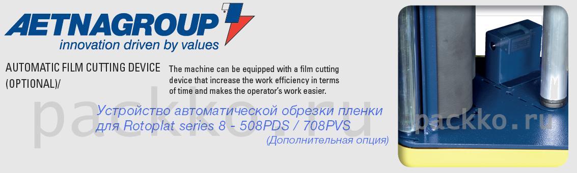
ROTOPLAT 708 PVS — паллетообмотчик полуавтоматического типа. Оснащен вращающимся столом. Поддерживает функцию регулирования предрастяжения пленки.
ROTOPLAT 708 PVS предназначен для обмотки грузов стретч-пленкой. Оснащен регулируемой кареткой в модификации PVS. Встроенное программное обеспечение позволяет программировать машину на выполнение самых различных операций.
Заказать звонок Отправить заявку
ROTOPLAT 708 PVS, также как и паллетообмотчик Masterwrap, может стать частью автоматизированной упаковочной линии. Модель подойдет для производственных объектов, логистических центров, складов.
Преимущества ROTOPLAT 708 PVS:
- Грузоподъемность стола составляет 2000 кг, что позволяет упаковывать даже объемные и тяжелые грузы.
- Регулируемая каретка PVS с двумя независимыми двигателями дает возможность предрастяжения пленки от 150 до 400 %. Управление возможно с цифровой панели.
- Предусмотрен фотодатчик, который автоматически определяет габариты груза после его установки на платформу.
- Есть датчик остановки. Если в зону каретки попал инородной предмет, механизм остановится.
- Погрузку можно производить с погрузчика, для которого в платформе предусмотрены специальные отверстия для вил.
Чтобы купить ROTOPLAT 708 PVS или паллетообмотчик Мобильный Робот, оставьте заявку на сайте или по телефону. Доставим продукцию в любой регион России.
Диаметр поворотного стола, мм
1650
Максимальный вес упаковываемого груза (включая поддон), кг
2000
Максимальная высота упаковываемого груза (включая поддон), мм
2200
Максимальный размер поддона (ш х д), мм
1000 x 1200
Высота от пола до верха поворотного стола, мм
77
Престрейч(предварительное растяжение), %
0-300
Остановка стола в фазе
±20 мм
Скорость вращения поворотного стола, Об./мин
4-12
Регулировка скорости вращения поворотного стола
Да
Скорость вертикального перемещения каретки, м/мин
1-4
Регулировка скорости вертикального перемещения каретки
Да
Электропитание, В-Ф-Г
230-1-50/60
Установленная мощность (номинальная), кВт
1.1
Вес аппарата (ориентировочный в базовой комплектации), кг
380-640
Для заказа ROTOPLAT 708 PVS оставьте заявку или позвоните на нашу горячую линию 8-800-707-51-79. Мы являемся филиалом завода ROBOPAC. Доставка и настройка модели ROTOPLAT 708 PVS по России и СНГ.
В паллетоупаковщике Rotoplat 708 PVS реализована система с регулируемой кареткой, оснащённой двумя двигателями: каждый работает независимо друг от друга. Механизм позволяет устанавливать натяжение пре–стретч от 150 до 400%. Одновременно осуществляется независимая регулировка натяжения плёнки на углах поддона, предотвращающая повреждение упаковки грузов.
Компания Robopac предлагает разные варианты упаковочного и фасовочного оборудования по типу готовой продукции, включая технику для бытовой химии, рыбы и морепродуктов, бакалеи, строительных материалов и других товаров пищевой и непищевой групп.
Особенности серии Rotoplat 708 PVS
Базовая комплектация включает поворотный стол, рассчитанный на паллеты до 2000 кг.
Оператор ставит груз в рабочую зону, после чего закрепляет край плёнки и запускает одну из программ. Высота определяется фотодатчиком, ещё один датчик контролирует движение каретки. Если на пути встретится препятствие, она немедленно остановится.
Функции управления:
- Количество слоёв плёнки в верхней и нижней частях паллеты.
- Уровень начала упаковки по высоте.
- Скорость вращения стола и движения каретки.
- Регулировка степени нахлёста
Остановка платформы происходит в том же положении, с которого начинается обмотка.
Помимо паллетоупаковщиков Robopac на сайте представлена фасовочная техника, аппараты для розлива, дозаторы, клипсаторы, тестоотсадочные машины и другое оборудование для организации линий полного цикла.
4.5.1. ELECTRIC BOX ASSEMBLY ……………………………………………………………………………………………………… 54
4.5.2. SLIDE SHAFT ASSEMBLY ………………………………………………………………………………………………………… 55
4.5.3. SLIDE SHAFT ASSEMBLY ………………………………………………………………………………………………………… 56
4.5.4.1.
LOADING DIRECTION MODIFICATION ……………………………………………………………………………… 58
4.6. MACHINE FIXING ……………………………………………………………………………………………………………………………. 65
4.9. PNEUMATIC CONNECTION …………………………………………………………………………………………………………….. 66
4.10. ELECTRICAL CONNECTION ………………………………………………………………………………………………………… 67
5. INFORMATION ON ADJUSTMENTS …………………………………………………………………………………………………. 68
5.4. ROTARY TABLE CHAIN ADJUSTMENT ……………………………………………………………………………………………. 72
6. INFORMATION ABOUT THE USE …………………………………………………………………………………………………….. 76
6.2. DESCRIPTION OF THE CONTROLS ………………………………………………………………………………………………… 77
6.3. DESCRIPTION OF USER INTERFACE ……………………………………………………………………………………………… 78
6.3.2. PROGRAMMING WINDOW ……………………………………………………………………………………………………….. 82
6.4. «HOME» PAGE ………………………………………………………………………………………………………………………………… 83
6.5. «MANUAL HANDLING» PAGE …………………………………………………………………………………………………………… 85
6.6. «RECIPES» PAGE ……………………………………………………………………………………………………………………………. 87
6.7. «WRAPPING CYCLE» PAGE …………………………………………………………………………………………………………….. 88
6.8. «GENERAL PARAMETERS» PAGE ……………………………………………………………………………………………………. 89
6.10. «HMI SETTINGS» PAGE ……………………………………………………………………………………………………………….. 91
6.11. «PASSWORD CHANGE» SCREEN ………………………………………………………………………………………………… 92
6.13. «SERVICE» SCREEN ……………………………………………………………………………………………………………………. 94
6.14. NEW RECIPE PROGRAMMING ……………………………………………………………………………………………………. 95
6.15. PHASE ANGLE ADJUSTMENT …………………………………………………………………………………………………….. 96
6.16. MACHINE SWITCHING ON AND OFF …………………………………………………………………………………………… 96
6.17. CYCLE PARAMETERS SETTING …………………………………………………………………………………………………. 97
6.18.1.
SINGLE WRAPPING CYCLE …………………………………………………………………………………………………. 97
6.18.2.
DOUBLE WRAPPING CYCLE ……………………………………………………………………………………………….. 97
6.18.3.
WRAPPING CYCLE WITH FEEDER ………………………………………………………………………………………. 98
6.19. CYCLE START AND STOP …………………………………………………………………………………………………………… 99
6.20. PRESSER HEIGHT CHANGE ……………………………………………………………………………………………………….. 99
6.21. PNEUMATIC CYLINDER WITH ROD …………………………………………………………………………………………… 100
6.21.1.
MECHANICAL PRESSER ……………………………………………………………………………………………………. 100
6.22. SPOOL LOADING ……………………………………………………………………………………………………………………… 101
6.23. «BUBBLE WRAP» SPOOL LOADING ……………………………………………………………………………………………. 102
7. MAINTENANCE INFORMATION ……………………………………………………………………………………………………… 103
ENG
Index
4
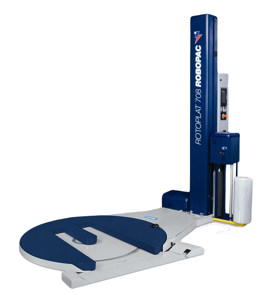
Полуавтоматический паллетоупаковщик Rotoplat 708 PVS
Серия Rotoplat это полная серия паллетообмотчиков, которая так же включает версию транспаллет для всех моделей. Технические характеристики и исполнение улучшались и совершенствовались компанией ROBOPAC на протяжении многих лет, благодаря опыту накопленному в производстве паллетообмотчиков с вращающейся платформой . Качество всех материалов используемых в этих паллетообмотчиках и высокие технические стандарты для всех механических и электрических компонентов в совокупности с высоко-эффективной и точной процедурой сборки и контроля позволяет создавать высоко-производительную, надёжную и безопасную продукцию. Паллетоупаковщики ROTOPLAT надёжные, лёгкие в эксплуатации и обслуживании и полностью соответствуют европейским стандартам безопасности.
Качество всех материалов используемых в этих паллетообмотчиках и высокие технические стандарты для всех механических и электрических компонентов в совокупности с высоко-эффективной и точной процедурой сборки и контроля позволяет создавать высоко-производительную, надёжную и безопасную продукцию. Паллетоупаковщики ROTOPLAT надёжные, лёгкие в эксплуатации и обслуживании и полностью соответствуют европейским стандартам безопасности.
| Технические характеристики | Ед.изм | Rotoplat 708PVS |
| Диаметр поворотного стола | мм | 1650 |
| Максимальный вес упаковываемого груза (включая поддон) | кг | 2000 |
| Максимальная высота упаковываемого груза (включая поддон) | мм | 2200 |
| Максимальный размер поддона (ш х д) | мм | 1000 x 1200 |
| Высота от пола до верха поворотного стола | мм | 77 |
| Модель каретки | — | PVS |
| Престрейч(предварительное растяжение) | % | 0-300 |
| Остановка стола в фазе | — | ±20 мм |
| Плавный пуск | — | Да |
| Скорость вращения поворотного стола | Об./мин | 4-12 |
| Регулировка скорости вращения поворотного стола | — | да |
| Скорость вертикального перемещения каретки | м/мин | 1-4 |
| Регулировка скорости вертикального перемещения каретки | — | да |
| Электропитание | В-Ф-Г | 230-1-50/60 |
| Установленная мощность (номинальная) | кВт | 1.1 |
| Вес аппарата (ориентировочный в базовой комплектации) | кг | 380-640 |
| Каталог запчастей (деталировка) | 1.83 Мб |
Тип каретки: 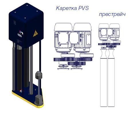
Каретка PVS — оснащена двумя независимыми электромоторами, позволяющими плавно регулировать степень пре-стретча в диапазоне от 0% до 400%, с шагом 10%.
Датчик натяжения плёнки, автоматически компенсирует натяжение на углах паллеты, предотвращая деформацию и повреждение продукции.
Функции доступные с панели управления: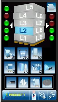
- Цветная 7-дюймовая сенсорная панель.
- Интуитивный интерфейс, быстрый загрузка панели (всего 10 сек.)
- Функция MULTI LEVEL CONTROL (MLC) – раздельная регулировка натяжения и предрастяжения плёнки по уровням.
- С панели управления можно регулировать:
- Скорость вращения платформы
- Натяжение плёнки
- Скорость перемещения каретки (вверх/вниз)
- Раздельная регулировка натяжения (вверх/вниз)
- Количество витков (в верхней/нижней части паллеты)
- Предрастяжение плёнки
- Задержка срабатывания фотодатчика (нахлёст плёнки)
- Начальная позиция каретки (расстояние от пола)
- Упаковочные циклы
- Режим укрытия верха
- Режим работы с прижимом
- Хранение в памяти до 6 программ с разными параметрами
Особенности паллетоупаковщиков 8 серии: 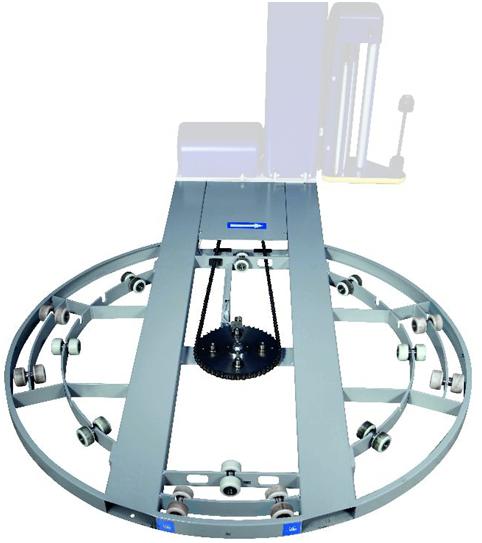
Поворотный стол В новых паллетообмотчиках Rotoplat 8-й серии количество роликов поворотной платформы увеличено с 8 до 14 пар роликов!
Основание паллетоупаковщиков Rotoplat позволяет осуществлять транспортировку вилочным погрузчиком (спереди и сзади). Цепь и система шестерёнок обеспечивают стабильность и надёжность во время вращения. Алмазный узор на поверхности стола обеспечивает лучшее сцепление для любых грузов и позволяет избежать их проскальзывания во время упаковки.
Основные опции:
- Поворотный стол диаметром 1800 мм;
- Подъездная рампа;
- Мачта для грузов высотой 2400 мм, 2800 мм, 3100 мм;
- Верхний прижим.