- Manuals
- Brands
- Ryobi Manuals
- Trimmer
- PLT-3043YW
- Operation manual
-
Contents
-
Table of Contents
-
Troubleshooting
-
Bookmarks
Quick Links
PLT-3043YW
TRIMMER
OWNER’S OPERATION MANUAL
N197
Related Manuals for Ryobi PLT-3043YW
Summary of Contents for Ryobi PLT-3043YW
-
Page 1
PLT-3043YW TRIMMER OWNER’S OPERATION MANUAL N197… -
Page 2
Fig. 1 Fig. 2 Fig. 3 Fig. 4 Fig. 5… -
Page 3
Fig. 7 Fig. 6 Fig. 8 Fig. 9 Fig. 10 Fig. 11… -
Page 4
Fig. 12 Fig. 13 Fig. 15 Fig. 14 Fig. 16 Fig. 17… -
Page 5
Fig. 18… -
Page 6
English SYMBOLS Important: Some of the following symbols may be used on your tool. Please study them and learn their meaning. Proper interpretation of these symbols will allow you to operate the tool better and safer. EXPLANATION SYMBOLS NAME Indicates danger, warning or caution. it means attention!!! Safety Alert Symbol Your safety is involved. -
Page 7
SAFETY trimmer, these parts get hot from operation. Always stop the engine and remove the spark plug wire Thank you for buying a Ryobi trimmer. before making any adjustments or repairs except for Your new trimmer has been engineered and carburetor adjustments. -
Page 8
43. Tabs air filter cover 46. «H» High needle SPECIFIC SAFETY RULES FOR TRIMMER USE 47. Anchor hole 44. Idle speed screw 48. Fuel cap 45. «L» Low needle Maintain a firm grip on both handles while trimming. Keep bump head below waist level. Never cut with the bump head located over 76 cm or more above the ground. -
Page 9
Carefully pour fuel mixture into the tank. Avoid spillage. OPERATION Prior to replacing the fuel cap, clean and inspect the gasket. Read the operation manual and follow all warnings and safety instructions. Immediately replace fuel cap and hand tighten. Wipe up any fuel spillage. -
Page 10
OPERATION 7. Run engine 15 to 30 seconds at full throttle (with trigger depressed fully) on half choke position ( ) to warm NOTE: If the line is worn too short you may not be able to up. Move choke lever to run position ( ) (16). -
Page 11
SPARK ARRESTOR MAINTENANCE The spark arrestor must be cleaned or replaced every 25 hours or yearly to ensure proper performance of your 3. To install the new spool, make sure the two lines are product. Spark arrestors may be in different locations captured in the slots (34) opposite each other on the new depending on the model purchased. -
Page 12
MAINTENANCE STORAGE (1 MONTH OR LONGER) 1. Drain all fuel from tank into a container approved for fuel. Run engine until it stops. 2. Clean all foreign material from the trimmer. Store it in a well-ventilated place that is inaccessible to children. Keep away from corrosive agents such as garden chemicals and de-icing salts. -
Page 13
TROUBLESHOOTING IF THESE SOLUTIONS DO NOT SOLVETHE PROBLEM CONTACTYOUR AUTHORIZED SERVICE AGENT. PROBLEM POS S IBLE CAUSE SOLUTION Engine does not reach full 1. Check oil fuel mixture. 1. Use fresh fuel and the correct 2-stroke oil mix. speed and emits excessive 2. -
Page 14
In the event of malfunction within the guarantee period, please return the product UNDISMANTLED with proof of purchase, to your dealer or nearest Ryobi Service Centre. Your statutory rights in respect of defective products remain unaffected by the warranty…
- Manuals
- Brands
- Ryobi Manuals
- Trimmer
- PLT-3043YW
- Operation manual
Hide thumbs
1
2
3
4
5
6
7
8
9
10
11
12
13
14
Table Of Contents
15
-
page
of
15/
15 -
Contents
-
Table of Contents
-
Troubleshooting
-
Bookmarks
Table of Contents
Advertisement
Enlarged version
35
31
37
36
41
47
37
Fig. 12
Fig. 13
36
34
38
Fig. 15
Fig. 14
41
39
40
42
43
Fig. 16
Fig. 17
Table of Contents
Previous Page
Next Page
- 1
- 2
- 3
- 4
- 5
- 6
- 7
- 8
Show Quick Links
- Quick Links:
-
Figures 1 — 5
-
Specification
-
Fuel and Refueling
-
Line Replacement
-
Troubleshooting
Hide quick links:
Advertisement
Table of Contents
Related Manuals for Ryobi PLT-3043YW
-
Trimmer Ryobi PLT3043S Operator’s Manual
String trimmer (20 pages)
-
Trimmer Ryobi PLT-3043S Owner’s Operation Manual
(15 pages)
-

Trimmer Ryobi PLT3043A, RY70101A Operator’s Manual
Ryobi trimmer operator’s manual (18 pages)
-
Trimmer RYOBI PLT3043A Operator’s Manual
String trimmer (18 pages)
-
Trimmer Ryobi PLT-3043A Owner’s Operation Manual
(14 pages)
-
Trimmer Ryobi PLT3043E, RY70103 Operator’s Manual
Ryobi outdoor trimmer operator’s manual (18 pages)
-
Trimmer Ryobi PLT3043E, RY70103A Operator’s Manual
Ryobi string trimmer operator’s manual (18 pages)
-
Trimmer Ryobi PLT-3043YA Owner’s Operation Manual
(16 pages)


-
Trimmer Ryobi PLT-2543 Owner’s Operation Manual
(13 pages)
-
Trimmer Ryobi P600 Manual Del Operador
18 volts (24 pages)
-
Trimmer Ryobi P600 Operator’s Manual
18 volt trimmer (22 pages)
-
Trimmer Ryobi P600 Manuel D’utilisation
French manual (22 pages)
-
Trimmer Ryobi P600 Operator’s Manual
18 volt trimmer (62 pages)
-
Trimmer Ryobi P2002 Operator’s Manual
18 volt string trimmer (34 pages)
-
Trimmer Ryobi P2603 Operator’s Manual
18 volt hedge trimmer (34 pages)
-
Trimmer Ryobi PBC3046B Operator’s Manual
Ryobi brush cutter user manual (22 pages)

Related Content for Ryobi PLT-3043YW
-
RLT430CES Description Of Figures
Ryobi RLT430CES
-
RY4CSS Figures
Ryobi RY4CSS
-
rlt4025 Description Of Figures
Ryobi rlt4025
-
RLT30CETG Description Of Figures
Ryobi RLT30CETG
-
RY34427, RY34447 Figures
Ryobi RY34427, RY34447
-
RY34426, RY34446 Figures
Ryobi RY34426, RY34446


-
RY34425, RY34445 Figures
Ryobi RY34425, RY34445
-
C430 Figures
Ryobi C430
-
RLT-1000EX Figures 7 — 12
Ryobi RLT-1000EX
-
RLT30CET Description Of Figures
Ryobi RLT30CET
-
P2005 Figures 1 — 6
Ryobi P2005


- Home
- Brands
- Ryobi Manuals
- Trimmer
- PLT-3043YW
Types of Manuals:
The main types of Ryobi PLT-3043YW instructions:
- User guide — rules of useing and characteristics
- Service manual — repair, diagnostics, maintenance
- Operation manual — description of the main functions of equipment
Trimmer User Guides by Ryobi:
Similar to Ryobi PLT-3043YW Manuals, User Guides and Instructions:
-
Ikra IATHS 40-43
Akku Teleskop-HeckenschereCordless Telescopic Hedge TrimmerTaille-haie à batterie sur percheTagliasiepi a batteria su astaAkumuliatorinė teleskopinė krūmapjovėAkumulatorske teleskopske škarje za živo mejoIATHS 40-4373711522-02Vor Inbetriebnahme Gebrauchsanweisung lesen!Gebrauchsanweisung — Originalbetriebsanleit …
IATHS 40-43 Trimmer, 96
-
Makita DUR192L
DUR192L ENCordless Grass Trimmer INSTRUCTION MANUAL 9SVBatteridriven grästrimmer BRUKSANVISNING 20NOBatteridrevet gresstrimmer BRUKSANVISNING 31FIAkkukäyttöinen viimeistelyleikkuriKÄYTTÖOHJE 42DAAkku græstrimmer BRUGSANVISNING 53LVBezvada zāles apgriezējmašīnaLIETOŠANAS INSTRUKCIJA 64LTBelaidė žoliapjovė …
DUR192L Trimmer, 112
-
Makita RT0700C
1 GB Trimmer INSTRUCTION MANUAL S Kantfräs BRUKSANVISNING N Tilskjæringsmaskin BRUKSANVISNING FIN Jyrsin KÄYTTÖOHJE LV Apgriezējmašīna LIETOŠANAS INSTRUKCIJA LT Profiliavimo staklės NAUDOJIMO INSTRUKCIJA EE Servamismasin KASUTUSJUHEND RUS Триммер РУКОВОДСТВО ПО ЭКСПЛУАТАЦИИ RT0 …
RT0700C Power Tool, 88
-
Makita HTR5600
HEDGE TRIMMERPEMANGKAS PAGARMÁY CẮT TỈA HÀNG RÀOเครื่องเล็มแนวรั้วพุ่มไม้WARNING:To reduce the RISK of injury, user must read and understand the instruction manual before using the Hedge Trimmer.Manufacturer reserves the right to change specications without no …
HTR5600 Trimmer, 60
-
Black & Decker LST136
1KEY INFORMATION YOU SHOULD KNOW:• The guard must be installed before trimming or edging — if not, the motor will overheat.• When replacing the line, use only .065 inch diameter ROUND line (B+D Model #AF-100 is recommended) — otherwise the tool will not function properly.• Do not bump the feed head against the gr …
LST136 Trimmer, 44

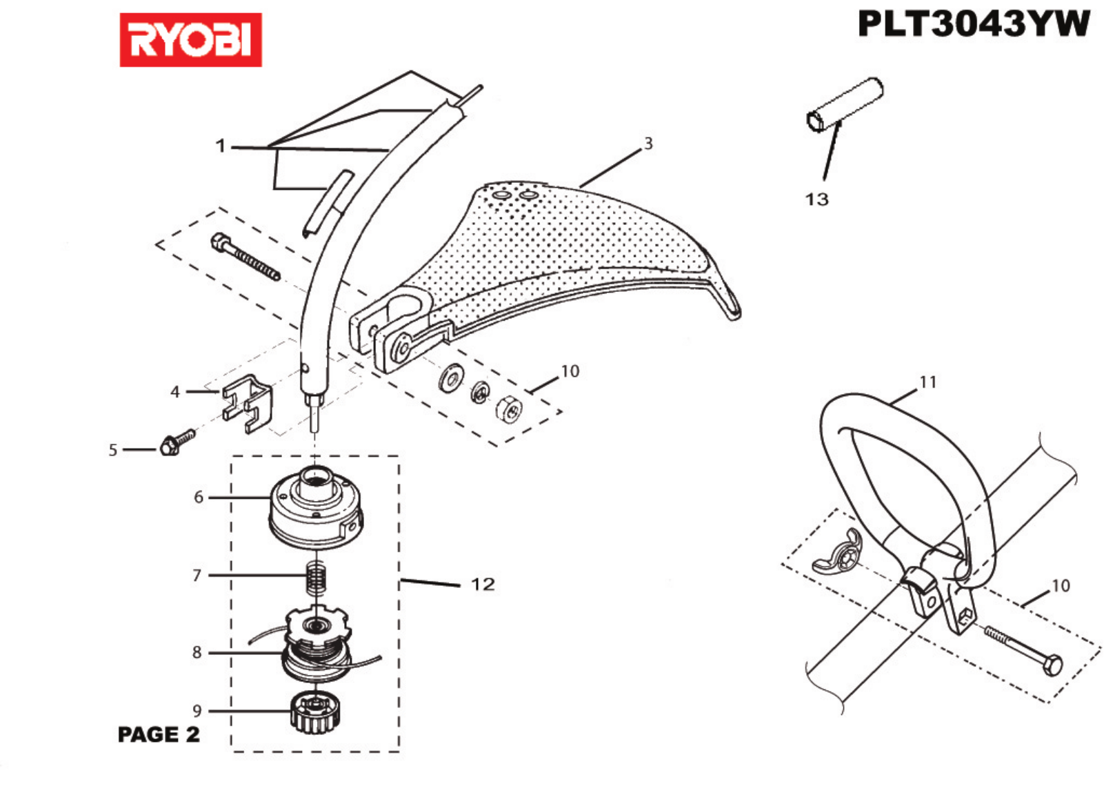
PLT-3043YW
TRIMMER
OWNER'S OPERATION MANUAL
N197
6
5
4
19
1
3
2
7
8
Fig. 1
7
14
9
12
20
10
11
9
12
13
Fig. 2
Fig. 3
21
22
24
23
25
26
53
Fig. 4
Fig. 5
29
27
28
20
Fig. 7
Fig. 6
19
4
16
5
17
3
18
15
Fig. 8
Fig. 9
35
31
34
33
30
32
Fig. 10
32
Fig. 11
35
31
37
36
41
47
37
Fig. 12
Fig. 13
36
34
38
Fig. 15
Fig. 14
41
39
40
42
43
Fig. 16
Fig. 17
44
45
46
Fig. 18
English
SYMBOLS
Important: Some of the following symbols may be used on your tool. Please study them and learn their meaning.
Proper interpretation of these symbols will allow you to operate the tool better and safer.
SYMBOLS
EXPLANATION
NAME
Safety Alert Symbol
Indicates danger, warning or caution. it means attention!!!
Your safety is involved.
Read Your Operator's Manual
Your manual contains special messages to bring attention to
potential safety concerns as well as operating and servicing
information. Please read all the information carefully to ensure
satification and safe use.
Wear eye and hearing protection
Wear eye and hearing protection when operating this
equipment.
Keep bystanders away
Keep all bystanders at least 15m (50 ft) away.
Ricochet
Danger of Ricochet.
No blade.
Do not install any type of blade on this unit.
RPM Decal
Rotational direction and maximum speed of the shaft for the
cutting attachment.
Boots
Wear non-slip safety footwear when using this equipment.
Gloves
Wear non-slip, heavy-duty gloves.
No Smoking
Do not smoke when mixing fuel or filling fuel tank.
Petrol
Use unleaded petrol intended for motor vehicle use with an
octane rarting of 87([R+M]/2) or higher.
Oil
Use synthetic 2-stroke oil for air cooled engines.
Mix Petrol and Oil
Mix the fuel mix thoroughly and also each time before
refuelling.
Switch
On/Off Switch
= ON to Run
O = OFF to Stop
Fully press and release the prime bulb 8 times.
Conforms to all regulatory standards in the country in the EU
where the product is purchased.
-1-
Do not touch area around the muffler or cylinder of the
trimmer, these parts get hot from operation.
SAFETY
Always stop the engine and remove the spark plug wire
before making any adjustments or repairs except for
carburetor adjustments.
Inspect the unit before each use for loose fasteners, fuel
leaks, etc. Replace any damaged parts before use.
The string head or blade will rotate during carburetor
adjustments.
It has been reported that vibrations from hand-held tools
may contribute to a condition called Raynaudʼs Syndrome in certain individuals. Symptoms may include
tingling, numbness and blanching of the fingers, usually
apparent upon exposure to cold. Hereditary factors,
exposure to cold and dampness, diet, smoking and work
practices are all thought to contribute to the development of these symptoms. It is presently unknown what,
if any, vibrations or extent of exposure may contribute to
the condition. There are measures that can be taken by
the operator to possibly reduce the effects of vibration:
a) Keep your body warm in cold weather. When operating the unit wear gloves to keep the hands and wrists
warm. It is reported that cold weather is a major
factor contributing to Raynaudʼs Syndrome.
b) After each period of operation, exercise to increase
blood circulation.
c) Take frequent work breaks. Limit the amount of
exposure per day.
Thank you for buying a Ryobi trimmer.
Your new trimmer has been engineered and
manufactured to Ryobiʼs high standard for dependability,
ease of operation, and operator safety. Properly cared
for, it will give you years of rugged, trouble-free
performance.
WARNING
To reduce the risk of injury, the user must read
and understand the operatorʼs manual.
WARNING
Do not attempt to operate this trimmer until you
have read thoroughly and understood completely
all instructions, safety rules etc contained in
this manual. Failure to comply may result in
accidents involving fire, electric shock or serious
personal injury. Save operatorʼs manual and
review frequently for continuing safe operation,
and instructing others who may use this tool.
READ ALL INSTRUCTIONS.
GENERAL SAFETY RULES
For safe operation, read and understand all instructions
before using the trimmer. Follow all safety
instructions. Failure to follow all safety instructions listed
below, can result in serious personal injury.
Do not allow children or untrained individuals to use this
unit.
Never start or run the engine in a closed or poorly
ventilated area; breathing exhaust fumes can kill.
Clear the work area before each use. Remove all objects
such as rocks, broken glass, nails, wire, or string which
can be thrown or become entangled in the bump head.
If you experience any of the symptoms of this condition,
immediately discontinue use and see your physician
about these symptoms.
Keep the tool well maintained, fasteners tightened
and worn parts replaced.
Mix and store fuel in a container approved for fuel.
Mix fuel outdoors where there are no sparks or flames.
Wipe up any fuel spillage. Move 9 m away from
refueling site before starting engine.
Stop the engine and allow to cool before refueling or
storing the unit.
Wear full eye and hearing protection while operating this
unit.
Wear heavy long pants, boots, and gloves. Do not wear
loose fitting clothing, short pants, jewellery of any kind,
or go barefoot.
Secure long hair so it is above shoulder level to prevent
entanglement in any moving parts.
Keep all bystanders, children, and pets at least 15 m
(50 ft.) away.
Do not operate this unit when you are tired, ill, or under
the influence of alcohol, drugs, or medication.
Do not operate in poor lighting.
Keep firm footing and balance. Do not overreach.
Overreaching can result in loss of balance or exposure
to hot surfaces.
Keep all parts of your body away from any moving part.
Allow the engine to cool; empty the fuel tank and secure
the unit from moving before transporting in a vehicle.
SPECIFIC SAFETY RULES FOR TRIMMER USE
Replace bump head if cracked, chipped, or damaged in
anyway. Be sure the bump head is properly installed
and securely fastened. Failure to do so can cause serious
injury.
Make sure all guards, straps, deflectors and handles are
properly and securely attached.
Use only the manufacturer's replacement line in the
cutting head. Do not use any other cutting attachment.
Never operate unit without the safety guard in place
and in good condition.
-2-
43. Tabs air filter cover
44. Idle speed screw
45. "L" Low needle
SPECIFIC SAFETY RULES FOR TRIMMER USE
Maintain a firm grip on both handles while trimming. Keep
bump head below waist level. Never cut with the bump
head located over 76 cm or more above the ground.
ASSEMBLY
SPECIFICATION
Weight
Without fuel and string head
4.69 Kg
Without fuel, w/string head
5.08 Kg
Fuel tank volume
425 cm3
Cutting swath
433 mm
Engine displacement
30 cc
Maximum engine performance
0.78 kW
(in accordance with ISO 8893)
-1
Maximum rotational frequency of the the spindle
9000 min
-1
Engine speed (rotational frequency) at
12500 min
recommended max. spindle rtational frequency
Engine speed (rotational frequency) at idle
2000-2500 min-1
Fuel consumption (in accordance with ISO 8893)
0.52 kg/h
at max. engine performance
Specific fuel consumption (in accordance with ISO 8893) 0.47 kg/h
at max. engine performance
Vibration level idling
Front handle
5.9 m/s 2
Rear handle
3.7 m/s 2
Vibration level racing
Front handle
8.2 m/s 2
Rear handle
8.6 m/s 2
Sound pressure level (in accordance with
1
ISO 7917:1987)
EN ISO1806:1997,
102 LpA(dBA)
Sound power level (in accordance with ISO 10884) 113 LwA (dBpA)
DESCRIPTION
1. Starter Grip
2. Shaft
3. Throttle Trigger
4. On / Off Switch
5. Safety Button
6. Engine Housing
7. Safety Guard
8. Cutting Line
9. Bolt
10. Flat Washer
11. Lock Washer
12. Wing nut
13. Bracket
14. Front handle
15. Choke lever
16. Run position
17. Half choke position
18. Full choke position
19. Primer bulb
20. Cutting blade
21. Rear Housing
46. "H" High needle
47. Anchor hole
48. Fuel cap
22. Torx Wrench
23. Muffler Guard
24. Screws
25. Bent End Of Muffler Guard
26. Opening In Rear Housing
27. Dangerous Cutting Area
28. Best Cutting Area
29. Direction Of Rotation
30. Bump knob
31. Spool
32. Eyelets
33. Bump head
34. Slots
35. Spring
36. Arrow on spool
37. First line
38. Second line
39. Latch
40. Cover
41. Filter
42. Slots on air filter
SAFETY GUARD (FIG. 2)
1. Remove wing nut (12), flat washer (10), lock washer (11),
and bolt (9) from the Owner's Kit.
2. Place safety guard (7) over shaft (2) and bracket (13).
3. Install bolt through the slots in the tabs on safety
guard and bracket on driveshaft housing.
4. Install flat washer, lock washer and wing nut.
4. Tighten Securely.
FRONT HANDLE (FIG. 3)
1. Remove the front handle (14), bolt, and wing nut from the
Ownerʼs Kit.
2. Install the front handle onto the top side of the drive
shaft housing and move it to a comfortable position.
3. Place the bolt through the front handle as shown, then
install the wing nut.
4. Tighten wing nut securely.
NOTE: Do not attempt to remove or modify the spacer.
This spacer limits the upper position of the handle grip.
MUFFLER GUARD ASSEMBLY (FIG. 4)
1. Remove muffler guard (23) and two screws (24) from the
owner's kit.
2. Attach the muffler guard to the rear housing (21).
NOTE:: Make sure the bent end of the muffler guard (25) fits
securely into the opening of the rear housing (26).
3. Using the torx wrench supplied, install the two screws
and tighten securely.
-3-
Carefully pour fuel mixture into the tank. Avoid spillage.
OPERATION
Prior to replacing the fuel cap, clean and inspect the
gasket.
Read the operation manual and follow all
warnings and safety instructions.
Immediately replace fuel cap and hand tighten. Wipe up
any fuel spillage. Move 9 m away from refueling
site before starting engine.
Wear eye protection and ear protection.
NOTE: It is normal for smoke to be emitted from a new
engine during and after first use.
Keep all by standers, especially children
and pets, at least 15m from the operating
area.
FUEL AND REFUELING
HANDLING THE FUEL SAFELY
Always handle petrol with care, it is highly flammable.
Always refuel outdoors where there are no sparks and
flames. Do not inhale petrol vapors.
Do not let petrol or oil come in contact with your skin.
Keep petrol and oil away from the eyes. If petrol or
oil comes in contact with the eyes, wash them immediately with clean water. If irritation is still present, see a
doctor immediately.
Clean up spilled fuel immediately.
MIXING THE FUEL
This product is powered by a 2-stroke engine and requires
pre-mixing petrol and 2- stroke oil. Pre-mix unleaded
fuel and 2- stroke engine oil in a clean container
approved for fuel.
This engine is certified to operate on unleaded petrol
intended for automotive use with an octane rating of 87
([R + M] / 2) or higher.
Do not use any type of pre-mixed petrol /oil from fuel
service stations, this includes the pre-mixed petrol /oil
intended for use in mopeds, motorcycles, etc.
Use synthinc 2-stroke oil only. Do not use automotive
oil or 2-stroke outboard oil.
Mix 2-stroke oil into the petrol at a 50:1 ratio.
Mix the fuel thoroughly and also each time before
fueling.
Mix in small quantities. Do not mix quantities larger than
usable in a 30 day period. A 2-stroke oil containing a fuel
stabilizer is recommended.
WARNING:
Always shut off engine before fueling. Never add fuel
to a machine with a running or hot engine. Move at
least 9 m from refueling site before starting engine.
Do not smoke!
1 Litre
2 Litres
3 Litres
4 Litres
5 Litres
+
+
+
+
+
20
40
60
80
100
ml
ml
ml
ml
ml
=
=
=
=
=
50:1
OPERATING THE TRIMMER (FIG. 5)
Hold the trimmer with the right hand on the rear handle and
the left hand on the front handle. Keep a firm grip with both
hands while in operation.Trimmer should be held at a
comfortable position with the rear handle about hip height.
Always operate trimmer at full throttle. Cut tall grass from
the top down.This will prevent grass from wrapping around
the shaft housing and bump head which may cause damage
from overheating. If grass becomes wrapped around the
bump head, stop the engine, disconnect the spark plug
wire, and remove the grass. Prolonged cutting at partial
throttle will result in oil dripping from the muffler.
ADVANCING THE LINE
ADVANCING LINE USING THE EZ LINETM TAP
ADVANCE SYSTEM
Line advance is controlled by tapping bump head on grass
while running engine at full throttle.
Run engine at full throttle.
Tap bump head on ground to advance line. Line
advances each time the head is tapped.
FILLING THE TANK
Clean surface around fuel cap to prevent contamination.
Loosen fuel cap slowly to release pressure and to keep
fuel from escaping around the cap.
-4-
Several taps may be required until line strikes the cut
off blade.
Resume trimming.
OPERATION
7. Run engine 15 to 30 seconds at full throttle (with trigger
depressed fully) on half choke position (
) to warm
up. Move choke lever to run position ( ) (16).
NOTE: If the line is worn too short you may not be able to
advance the line by tapping it on the ground. If so, STOP
THE ENGINE, and manually advance the line.
TO START A WARM ENGINE:
1. Press swith (4) to "I" (RUN) position.
2. Move choke lever to run position ( ).
3. Hold trigger and pull starter grip until engine runs.
ADVANCING THE LINE MANUALLY
Push the bump knob down while pulling online(s) to
manually advance the line.
CUTTING TIPS (FIG. 6)
Keep the trimmer tilted toward the area being cut; this is
the best cutting area (28).
Do not cut in dangerous cutting area (27).
NOTE: Do not pull the starter grip any more than 5 times
as more than this can cause the engine to flood. If the
engine fails to start after 3 – 5 pulls, immediately repeat
steps 5 – 8.
Use the tip of line to do the cutting; do not force bump
head into uncut grass.
TO STOP THE ENGINE:
To stop the engine, depress the switch to "O" position.
Wire and picket fences cause extra line wear, even
breakage. Stone and brick walls, curbs, and wood may
wear line rapidly.
Avoid trees and shrubs. Tree bark, wood moldings,
siding, and fence posts can easily be damaged by the
line.
NOTE: Be sure to return the stop switch to the "I" (RUN)
position before trying to start unit.
MAINTENANCE
WARNING:
SAFETY GUARD LINE TRIMMING CUTOFF BLADE (FIG. 7)
Use only original manufacturer's replacement parts,
accessories and attachments. Failure to do so can
cause possible injury, poor performance and may
void your warranty.
This trimmer is equipped with a line trimming cut-off blade
on the safety guard.. For best cutting, advance line until
it is trimmed to length by the cut-off blade. Advance line
whenever you hear the engine running faster than normal.
This will maintain best performance and keep line long
enough to advance properly.
You may make adjustments and repairs described here.
For other repairs, have the trimmer serviced by an
authorized servicing agent.
Consequences of improper maintenance may include
excess carbon deposits resulting in loss of performance
and discharge of black oily residue dripping from the
muffler.
Make sure all guards, straps, deflectors and handles are
properly and securely attached to avoid the risk of
personal injury.
STARTING AND STOPPING (FIG. 8 & 9)
WARNING
Never start or run the engine inside a closed or poorly
ventilated area; breathing exhaust fumes can kill.
TO START A COLD ENGINE:
1. Lay trimmer on a flat, bare surface. Press switch (4) to "I"
(RUN) position.
SPOOL REPLACEMENT
EZ LINETMTAP ADVANCE SYSTEM
NOTE: Unit is equipped with a positive on-off switch,
make sure switch is in the "I" (RUN) position before
starting the unit.
2. Push primer bulb (19) 8 to 10 times.
3. Set choke lever (15) to full choke position (
)(18).
4. Depress safety button (5), squeeze trigger (3) and pull starter grip (1)
until engine tries to run. (No more than 6 pulls.)
5. Set choke lever to half choke position (
) (17).
NEW PREWOUND SPOOL (FIG. 10 & 11)
If replacing line only, refer to "Line Replacement" later in
this manual.
Use only 2.0 mm diameter monofilament line.
Use the manufacturer's replacement line for best performance.
Stop the engine, disconnect the sparkplugwire. Hold
thebumphead (33 )andunscrew thebump knob(30).Turn
clockwise.
Remove the empty spool (31)from the bump head. Keep
thespring (35)attachedtothe spool.
6. Hold trigger and pull starter grip until engine runs.
NOTE: If the engine fails to start, immediately repeat steps
3 – 6 or refer to the TROUBLE SHOOTING at the back of
this manual. As the engine could be flooded, faulty or worn
spark plug, low or incorrect fuel or is in need for a service.
-5-
SPARK ARRESTOR
MAINTENANCE
3. To install the new spool, make sure the two lines are
captured in the slots (34) opposite each other on the new
spool. Make sure the ends of each string is extended
approximately 152 mm beyond each slot.
4. Thread the lines into the eyelets (32) in the bump head.
Carefully push the spool into the bump head (gently pull
the lines to the outside if necessary). When the spool
is positioned in the bump head, grasp the lines and
pull sharply to release them from the slots in the spool.
5. Push down and turn the spool counterclockwise until it
no longer turns. Hold the spool down and rotate clockwise a small amount. Release the spool. The spool
should be locked down in the bump head. If not, hold
down and rotate until locked.
6. Make sure the bump head and the bump knob are
installed on the drive connector by turning the knob
counter-clockwise to tighten.
7. Pull the lines again to rotate the spool into cutting
position. Push the bump knob down while pulling on
line(s) to manually advance the line and to check for
proper assembly of the bump head.
The spark arrestor must be cleaned or replaced every 25
hours or yearly to ensure proper performance of your
product. Spark arrestors may be in different locations
depending on the model purchased. Please contact your
nearest service dealer for the location of the spark arrestor
for your model.
Cleaning Instructions:
Remove the spark arrestor from the muffler.
If your spark arrestor is made of a fiberglass material,
discard and replace.
If your spark arrestor is made of a metal material follow
these cleaning instructions:
1. Spray the spark arrestor with a quality carbon
cleaner.
2. Gently clean using a wire brush.
3. Install the new or cleaned spark arrestor and reassemble completely before use.
REPLACING AND CLEANING AIR FILTER (FIG. 16 & 17)
For proper performance and long life, keep air filter clean.
1. Remove the air filter cover by pushing down on the latch (39)
with your thumb while gently pulling on the cover (40).
2. Remove the filter (41), clean it in warm soapy water. Rinse
and let dry completely. For best performance, replace
annually.
LINE REPLACEMENT (FIG. 12 - 15)
1. Stop the engine, disconnect the spark plug wire.
Hold the bump head and unscrew the bump knob.
Turn clockwise.
2. Remove the spool from the bump head. NOTE:
Keep the spring attached to the spool. Remove any
old line remaining on the spool.
3. Cut two pieces of string, each being approximately
2.7 m long.
4. Insert the first line (37) into the anchor hole (47) in the
upper part of the spool. Wind the first line around
the upper part of the spool counterclockwise, as
shown by the arrows on the spool (31). Place line in
the slot on upper spool flange, leaving about 152
mm extended beyond the slot. Do not overfill.
After winding the line, there should be at least 6
mm between the wound line and the outside edge
of the spool.
5. Repeat above step with second line (38), using the
bottom part of spool. Do not overfill.
3. Install the filter, align tabs, push in, and make sure the
latches are locked into place.
FUEL CAP
WARNING:
A leaking fuel cap is a fire hazard and must be
replaced immediately.
The fuel cap (48) contains a non-serviceable filter and a check
valve. A clogged fuel filter will cause poor engine performance. If performance improves when the fuel cap is
loosened, check valve may be faulty or filter clogged.
Replace fuel cap if required.
SPARK PLUG
6. Replace the spool and the bump knob. Refer to
"Spool Replacement " earlier in this manual.
CLEANING THE EXHAUST PORT AND MUFFLER
This engine uses a Champion RCJ-6Yand NGK BPMR7A
with 0.63 mm electrode gap. Use an exact replacement
and replace annually.
Depending on the type of fuel used, the type and amount of
oil used, and/or your operating conditions, the exhaust port
and muffler may become blocked with carbon deposits. If
you notice a power loss with your petrol powered tool, a
qualified service technician will need to remove these
deposits to restore performance.
-6-
MAINTENANCE
STORAGE (1 MONTH OR LONGER)
1. Drain all fuel from tank into a container approved for
fuel. Run engine until it stops.
2. Clean all foreign material from the trimmer. Store it in a
well-ventilated place that is inaccessible to children.
Keep away from corrosive agents such as garden
chemicals and de-icing salts.
3. Cover the blade with the blade protector before storing
the unit, or during transportation.
4. Abide by all ISO and local regulations for the safe
storage and handling of petrol. Excess fuel should be
used up in other 2-stroke engine powered equipment.
TROUBLESHOOTING
IF THESE SOLUTIONS DO NOT SOLVETHE PROBLEM CONTACTYOUR AUTHORIZED SERVICE AGENT.
PROBLEM
Engine will not start:
POSSIBLE CAUSE
SOLUTION
1. No spark.
2. No fuel.
3. Flooded engine.
4. Starter rope pulls harder now than
when new.
1. Check spark. Remove spark plug. Reattach the
spark plug cap and lay spark plug on metal
cylinder. Pull the starter rope and watch for
spark at spark plug tip. If there is no spark,
repeat test with a new spark plug.
2. Push primer bulb until bulb is full of fuel. If bulb
does not fill, primary fuel delivery system is
blocked. Contact a servicing agent. If primer
bulb fills, engine may be flooded (see next
item).
3. Remove spark plug, turn trimmer so spark plug
hole is aimed at the ground. Make sure lever is
in the " WARM START " position and pull starter
cord 10 to 14 times. This will clear excess fuel
from engine. Clean and reinstall spark plug.
With the throttle trigger fully depressed, pull
starter cord three times with lever at " WARM
START " position. If engine does not start,
move choke lever to" COLD START " and follow
normal starting instructions in "STARTING
AND STOPPING" section. If engine still fails to
start, repeat procedure with a new spark plug.
4. Contact a servicing agent.
Lever will not go into the
"COLD START" position:
Throttle trigger is depressed.
Release throttle trigger. Refer to"Starting and
Stopping" earlier in this manual.
Engine starts but will not
accelerate:
Carburetor requires adjustment.
*Turn" L " needle counterclockwise 1/16 turn. If
"L" low needle (48)can not be turned counterclockwise, do not force plastic limiter caps. Contact a
servicing agent (Fig. 18).
-7-
TROUBLESHOOTING
IF THESE SOLUTIONS DO NOT SOLVETHE PROBLEM CONTACTYOUR AUTHORIZED SERVICE AGENT.
PROBLEM
Engine does not reach full
speed and emits excessive
smoke:
POS
SIBLE CAUSE
SOLUTION
1. Check oil fuel mixture.
2. Air filter dirty.
3. Carburetor requires adjustment.
1. Use fresh fuel and the correct 2-stroke oil mix.
2. Clean air filter. Refer to" Replacing and
Cleaning Air Filter" earlier in this manual.
3. Turn"H" needle (49) clockwise 1/16 - 1/8 turn (Fig. 18).
Engine starts, runs, and
accelerates but will not idle:
Carburetor requires adjustment.
Turn idle speed screw (50)clockwise to increase
idle speed (Fig. 18).
Line will not advance:
1. Line welded to itself.
2. Not enough line on spool.
1. Lubricate with silicone spray.
2. Install more line. Refer to "Line Replacement"
earlier in this manual.
3. Pull lines while alternately pressing down on
and releasing bump knob.
4. Remove line from spool and rewind. Refer to
"Line Replacement" earlier in this manual.
5. Advance line at full throttle.
3. Line worn too short.
4. Line tangled on spool.
5. Engine speed too slow.
Grass wraps around
shaft housing and bump
head:
1. Cutting tall grass at ground
level.
2. Operating trimmer at part
throttle.
1. Cut tall grass from the top down.
Bump knob hard to
turn:
Screw threads dirty or damaged.
Clean threads and lubricate with grease - if no improvement, replace bump knob.
1. Operating trimmer at part
throttle
2. Check oil/fuel mixture.
3. Air filter dirty.
4. Carburetor requires adjustment.
1. Operate trimmer at full throttle.
Oil drips from muffler:
2. Operate trimmer at full throttle.
2. Use fresh fuel and the correct 2-stroke oil mix.
3. Clean per instruction in Maintenance Section.
4. Turn"H" needle clockwise 1/16 - 1/8 turn (Fig. 18).
NOTE: The carburetor adjustment needle(s) are equipped with plastic cap(s) that prevents counterclockwise rotation from the
original factory adjustment. If your unit exhibits specific performance problem(s) where theTrouble Shooting Section recommends
a counterclockwise needle adjustment and no adjustments have been made since original purchase, the unit should be taken
to a factory authorized service agent for repair. In most cases, the needed adjustment is a simple task for the factory trained
service representative.
-8-
GUARANTEE - STATEMENT
This product is guaranteed from defects in material and workmanship, for a period of 24 months, effective and
evidenced from date of original invoice or delivery note.
Defects caused by normal wear and tear, unauthorized / improper maintenance/handling or overload are excluded
from this guarantee as are accessories such as battery packs, bulbs, blades and bits, etc.
In the event of malfunction within the guarantee period, please return the product UNDISMANTLED with proof of
purchase, to your dealer or nearest Ryobi Service Centre.
Your statutory rights in respect of defective products remain unaffected by the warranty
EC DECLARATION OF CONFORMITY
We declare in sole responsibility that the product: - to which this certificate applies,conforms to the basic health and
safety requirements of the Machinery Directive 98/37/EC and other relevant directives, like EMC Directive 89/336/EEC and
Outdoor Directive 2000/14/EC,79/113/EEC.
To effect correct application of the health and safety requirements stated in the EEC directives,the following European and/or
national standards and/or technical specifications were consulted: EN ISO 14982:1998, ISO 7916 & 7917, EN ISO 11806:1997,
ISO 7918-1995, ISO 8380-1993, ISO 8893-1989, ISO 10884-1995. EN 292-1.1991, EN 292-2-1991, EN 292-2:1991/A1;1995,
EN 563-1994, EN 27917-1991, ISO 7112-1982, ISO 7113-1991.
We declare this product complies to the requirements of the Outdoor Directive 2000/14/EC.
Measured Sound Power Level :
Guaranteed Sound Power Level :
Date of issuance :
112 dB(A)
113 dB(A)
April 2005
This product has been assessed to conform to the Outdoor Directive 2000/14/EC by means of unit verification by SLG
PRUEF-UND ZERTIFIZIERUNGS GMBH. BURGSTAEDTER STRASSE 20, D-09232, HARTMANNSDORF,GERMANY.
Technical documents are kept by Homelite Far East Co.,Ltd. 24/F, 388 Castle Peak Road, Tsuen Wan, N.T., Hong Kong.
Declared in April 2005 by Homelite Far East Co.,Ltd.
Machine: TRIMMER
Name of company:
Address:
Type: PLT-3043YW
Ryobi Technologies (UK) Limited.
ANVIL HOUSE, TUNS LANE,
HENLEY-ON-THAMES,
OXFORDSHIRE, RG9 1SA
UNITED KINGDOM
Name / title: Mark Pearson
Managing Director
Signature:
Tel: +44-1491-848700 Fax: +44-1491-848701
Name of company:
Address:
RYOBI TECHNOLOGIES AUSTRALIA PTY. LTD
A.B.N. 98 002 277 509
SYDNEY : 359-361 Horsley Road,
Milperra, N.S.W. 2214.
Tel: (02) 9792 9800 Fax: 1800 807 993
Name of company:
Address:
RYOBI TECHNOLOGIES NEW ZEALAND PTY. LTD
27 Clemow Drive, Mt Wellington
PO Box 12-806, Penrose, Auckland
New Zealand
Tel: (09) 573 0230 Free Call: 0800 279 624 Fax: (09)573 0231
Welcome to ManualMachine
You have been successfully registered
We have sent a verification link to to complete your registration.
If you can’t find the email, check your Junk/Spam folder.


- Buy Points
- How it Works
- FAQ
- Contact Us
- Questions and Suggestions
- Users

 Loading…
You can only view or download manuals with
Sign Up and get 5 for free
Upload your files to the site. You get 1 for each file you add
Get 1 for every time someone downloads your manual
Buy as many as you need
View and download manuals available only for
Register and get 5 for free
Upload manuals that we do not have and get 1 for each file
Get 1 for every download of your manual
Buy as much as you need