-
Contents
-
Table of Contents
-
Bookmarks
Quick Links
©
Saab Automobile AB 2006
Service Readiness, Saab Automobile AB, Trollhättan, Sweden
Printed in Sweden
Saab 9-5, Model Year 2007
Instruments and controls
Saab 9-5 Audio System 3
Interior equipment and trunk 113
Car care and technical information 189
Customer Assistance and Information 251
Owner’s Manual
Safety
Security
Starting and driving 139
Specifications 257
1
11
43
57
90
Index 271
Chapters
Related Manuals for Saab 2007 9-5
Summary of Contents for Saab 2007 9-5
Некоторое непродолжительное время у меня находилась шикарная книга по руководству, ремонту и обслуживанию SAAB 9-5

Я решила ее отсканировать ну и собственно предложить вам ее в электронном виде, совершенно безвозмездно! Ссылка на dropbox лежит здесь
Думаю она пригодится многим…
PS:Единственное, при сканировании пропустила, не могу понять каким образом, два листа (стр, стр. 24-25 и 60-61), если смогу добраться к книге еще раз, отфотографирую недостающее и добавлю! Так что прошу простить и не кидаться в меня тапками)))
Посмотреть инструкция для Saab 9-5 (2004) бесплатно. Руководство относится к категории автомобили, 2 человек(а) дали ему среднюю оценку 6.4. Руководство доступно на следующих языках: английский. У вас есть вопрос о Saab 9-5 (2004) или вам нужна помощь? Задайте свой вопрос здесь
Не можете найти ответ на свой вопрос в руководстве? Вы можете найти ответ на свой вопрос ниже, в разделе часто задаваемых вопросов о Saab 9-5 (2004).
Как перевести мили в километры?
Где я могу узнать идентификационный номер транспортного средства Saab?
Что такое идентификационный номер транспортного средства (VIN)?
Когда транспортному средству Saab требуется техническое обслуживание?
Когда следует заменять тормозную жидкость на Saab?
В чем разница между топливом E10 и E5?
Одна или несколько дверей не открываются изнутри. Что мне делать?
Автомобильный радиоприемник не включается, что делать?
Инструкция Saab 9-5 (2004) доступно в русский?
Не нашли свой вопрос? Задайте свой вопрос здесь
Дилерское мультимедийное руководство на английском языке по техническому обслуживанию и ремонту автомобилей выпущенных концерном GM в 1980-2009 годах.
- Автор: —
- Издательство: GM
- Год издания: —
- Страниц: —
- Формат: ISO
- Размер: 6,5 Gb
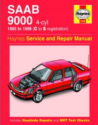
Руководство на английском языке по техническому обслуживанию и ремонту автомобиля Saab 9000 1985-1998 годов выпуска с четырехцилиндровыми двигателями.
- Автор: —
- Издательство: Haynes Publishing
- Год издания: 2001
- Страниц: 256
- Формат: PDF
- Размер: 90,4 Mb
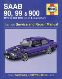
Руководство на английском языке по техническому обслуживанию и ремонту автомобилей Saab 90/99/900 1979-1993 годов выпуска.
- Автор: A.K. Legg
- Издательство: Haynes Publishing
- Год издания: 1989
- Страниц: 308
- Формат: PDF
- Размер: 361,7 Mb
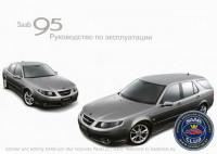
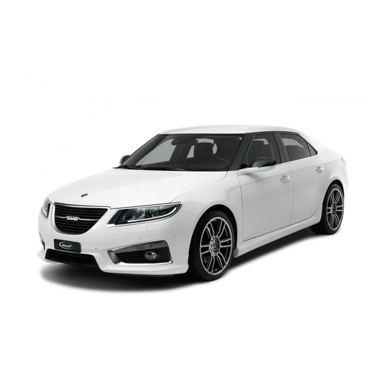
Руководство по техническому обслуживанию и ремонту автомобиля Saab 9-5.
- Автор: —
- Издательство: SAAB
- Год издания: 2007
- Страниц: 274
- Формат: DjVu
- Размер: 3,5 Mb
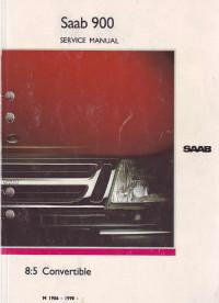
Сборник руководств на английском языке по техническому обслуживанию и ремонту автомобиля Saab 900.
- Автор: —
- Издательство: SAAB
- Год издания: —
- Страниц: —
- Формат: PDF
- Размер: 118,5 Mb
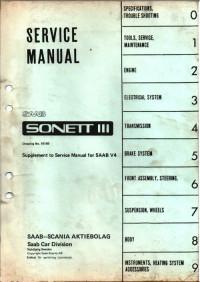
Руководство на английском языке по техническому обслуживанию и ремонту автомобиля Saab Sonett III.
- Автор: —
- Издательство: SAAB
- Год издания: 1973
- Страниц: 162
- Формат: PDF
- Размер: 20,3 Mb
Руководство на английском языке по техническому обслуживанию и ремонту автомобилей Saab 95 и SAAB 96.
- Автор: —
- Издательство: SAAB
- Год издания: 1973
- Страниц: 648
- Формат: PDF
- Размер: 53,1 Mb

Мультимедийная информационная система для станций техобслуживания по автомобилю Saab 900. Мультиязычный интерфейс (русского языка нет).
- Автор: —
- Издательство: SAAB
- Год издания: —
- Страниц: —
- Формат: —
- Размер: 522,2 Mb
Мультимедийная информационная система для станций техобслуживания по автомобилям Saab 9-3/9-4/9-5. Мультиязычный интерфейс (русский язык присутствует).
- Автор: —
- Издательство: SAAB
- Год издания: 2012
- Страниц: —
- Формат: —
- Размер: 3,6 Gb
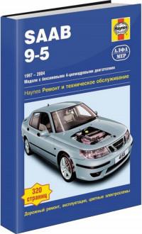
Руководство по техническому обслуживанию и ремонту автомобиля Saab 9-5 1997-2004 годов выпуска с бензиновыми двигателями.
- Автор: —
- Издательство: Алфамер
- Год издания: —
- Страниц: 320
- Формат: —
- Размер: —
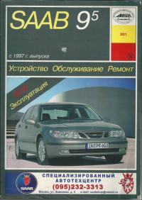
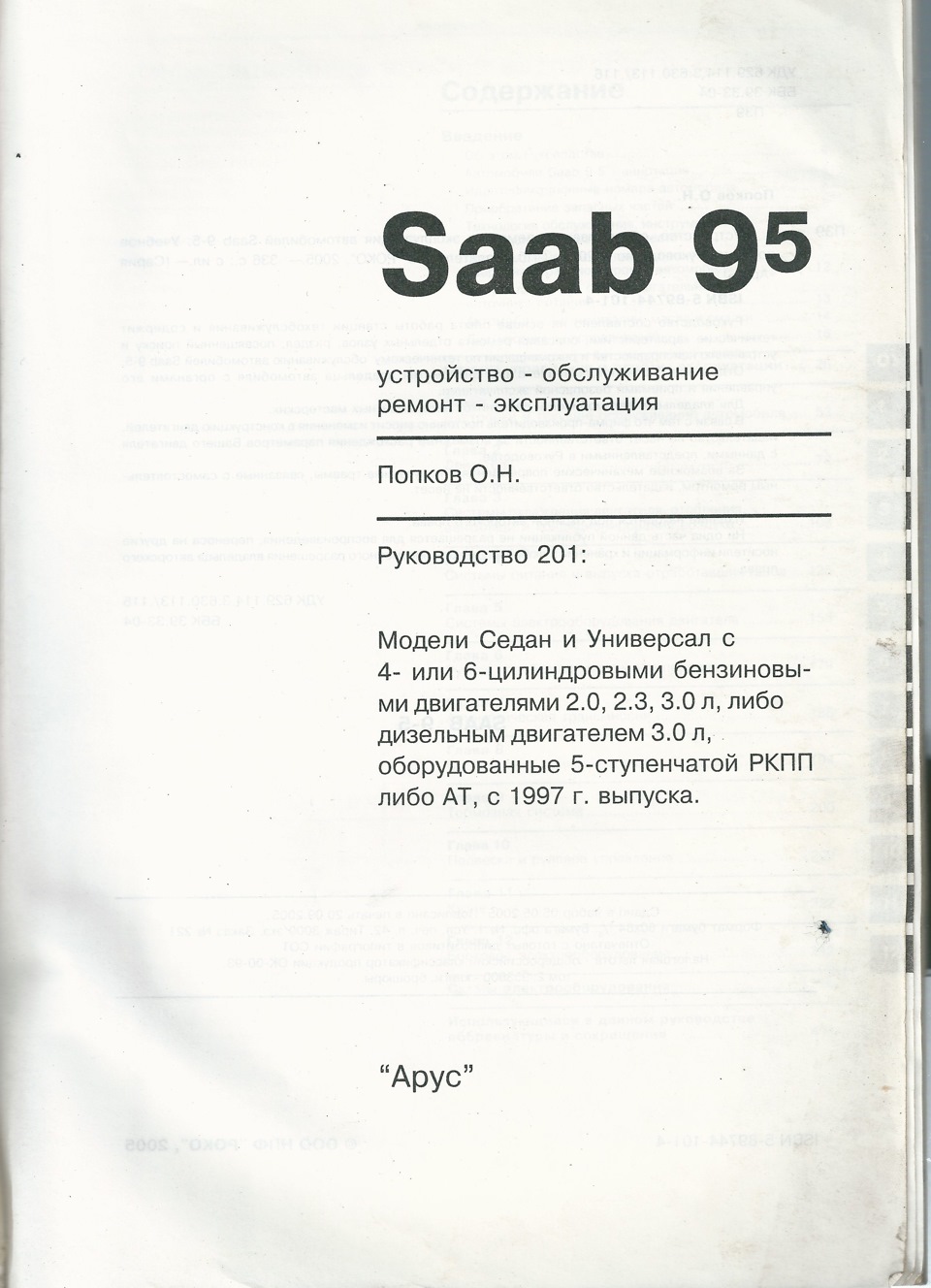
Руководство по эксплуатации, техническому обслуживанию и ремонту автомобиля Saab 9-5 с 1997 года выпуска.
- Автор: —
- Издательство: Арус
- Год издания: 2005
- Страниц: 331
- Формат: PDF
- Размер: 517,8 Mb
Руководство по эксплуатации, техническому обслуживанию и ремонту автомобиля Saab 9000 с 1985 года выпуска.
- Автор: —
- Издательство: Арус
- Год издания: —
- Страниц: 270
- Формат: —
- Размер: —
Мультимедийное руководство по техническому обслуживанию и ремонту автомобиля Saab 9000 с 1985 года выпуска.
- Автор: —
- Издательство: —
- Год издания: —
- Страниц: —
- Формат: —
- Размер: 108,2 Mb
Мультимедийное руководство по техническому обслуживанию и ремонту автомобиля Saab 9-5 с 1997 года выпуска.
- Автор: —
- Издательство: —
- Год издания: —
- Страниц: —
- Формат: ISO
- Размер: 89,7 Mb

- Manuals
- Brands
- Saab Manuals
- Automobile
- 9-5 2011
- Owner’s manual
-
Contents
-
Table of Contents
-
Bookmarks
Quick Links
Chapters
-
Table of Contents
2 -
Windows
20 -
36 Seats, Restraints Head Restraints Position
37 -
Instruments and Controls Steering Wheel Controls Controls
92 -
Driving and Operating Driving Hints Starting and Operating New Vehicle Break-In
148 -
179 Vehicle Care General Information Accessories and Modifications California Proposition 65
180
Related Manuals for Saab 9-5 2011
Summary of Contents for Saab 9-5 2011
-
Page 2: Table Of Contents
Contents Introduction ……..2 In brief ……….8 Keys, doors and windows …. 19 Seats, restraints ……36 Storage ……..82 Instruments and controls ….. 91 Lighting ……..128 Climate control ……137 Driving and operating ….147 Vehicle care ……. 179 Service and maintenance ..
-
Page 3: Introduction
Introduction Introduction…
-
Page 4
Although this manual describes the country specifications, special Since the policy at Saab is one of con‐ most important differences between equipment, or accessories. tinual improvement, we retain the model variants, it does not specify the right to incorporate modifications and ■… -
Page 5
Introduction ■ Directional data, e.g., left or right, or Refrigerant at high pressure. Caution front or back, always relates to the Do not loosen or remove the A/C sys‐ travel direction. tem fittings before discharging the Text marked Caution provides in‐ ■… -
Page 6
Introduction ■ No sparks, naked flames or smok‐ The warning label is located in the en‐ AIR BAGS ing. gine compartment. ■ Always shield eyes. Explosive NETTOYER LE BOUCHON DE RE‐ gases can cause blindness or in‐ MPLISSAGE AVANT DE L’ENLE‐ jury. -
Page 7
3. 3 means «see page». dynamometer. Changing wheels The warning label is located in the en‐ gine compartment. Contact a Saab dealer if a xenon headlamp requires replacement. This label is only found on cars with xenon headlamps. All-wheel drive cars The warning label is located under the tailgate. -
Page 8
Introduction… -
Page 9: In Brief
In brief In brief Unlocking the Vehicle Passive Entry System Remote Control System Initial drive information Pull the door handle to unlock the ve‐ hicle and to open the door. To open the trunk lid, press the button under Press button c to unlock the doors the molding.
-
Page 10
In brief Seat Adjustment Head Restraint Adjustment Safety Belt Power seat adjustment Press release button, adjust height, Pull out the safety belt and engage in engage. belt buckle. The safety belt must not Operate switches. be twisted and must fit close against The headrest must not be in highest the body. -
Page 11
In brief Mirror adjustment Steering Wheel Exterior mirrors Adjustment Interior mirror Select the relevant exterior mirror and adjust. Unlock lever, adjust steering wheel, Swivel mirror housing into right posi‐ Exterior mirrors 3 30, Electric ad‐ then engage lever and ensure it is tion. -
Page 12
In brief… -
Page 13
In brief Instrument panel overview 10 Head-Up display ….112 25 Traction Control system ..160 Electronic stability 11 Windshield wiper, Exterior Lamp Controls ..128 program ……155 windshield washer Front fog lamps ….131 Drive sense ……161 system, headlamp washer Instrument illumination .. -
Page 14
In brief Exterior lighting Flash-to-Pass, headlamp High/ Turn and lane-change signals Low-Beam Changer Right = lever up Turn signal lamp switch Left = lever down Flash-to-Pass = pull lever = Activation or deactivation of High-Beam On = push lever the automatic light control Turn and lane-change signals Light Auto = Automatic light control:… -
Page 15
In brief Horn Washer and Wiper Hazard warning flashers Systems Windshield wiper Operated with the ¨ button. Press j. Hazard warning flashers 3 130. = fast continuous = slow continuous P = automatic wiping with rain sen‐ § = off For a single sweep when the wind‐… -
Page 16
In brief Climate Control Windshield and headlight Demisting and Defrosting washer systems Windows Heated Rear Window, Heated Mirrors Press button V. Pull lever. Temperature and air distribution are Windshield and headlight washer Heating is operated by pressing the set automatically and the fan runs at system 3 92, Washer fluid 3 188. -
Page 17
In brief Transmission Automatic transmission The selector lever can only be moved out of P when the ignition is on and the brake pedal is applied. To engage Manual transmission P or R, push the release button. Automatic transmission 3 153. P = Park R = Reverse N = Neutral… -
Page 18
In brief Starting off Parking Starting the engine ■ Always apply parking brake. Pull Check before starting off or switch m on the center console. taking a long trip ■ If the vehicle is on a level surface or ■ Tire pressure and condition uphill slope, set the selector lever to 3 215. -
Page 19
In brief ■ The engine cooling fans may run after the engine has been switched off 3 182. ■ After running at high engine speeds or with high engine loads, operate the engine briefly at a low load or run in neutral for approx. 30 seconds, before switching off in order to protect the turbocharger. -
Page 20: Keys, Doors And Windows
Keys, doors and windows Keys, doors and Keys, locks The remote control has an approxi‐ mate range of up to 164 ft. It can be windows restricted by external influences. The Radio remote control hazard warning flashers confirm op‐ eration. Handle with care, protect from mois‐…
-
Page 21
Keys, doors and windows Welcome lighting 3 135 Memorized settings lock or lock driver’s door, if the remote control or the passive entry system Whenever the ignition is switched off Panic alarm fails. and the driver’s door is opened, the Press and hold button B for at least following settings are automatically three seconds to activate the panic… -
Page 22
Keys, doors and windows Battery replacement of remote 1. Press the button on the remote Fault control and extract the key blade control If the central locking system does not from the housing. operate, it may be due to the follow‐ Replace the battery as soon as the 2. -
Page 23
Keys, doors and windows This number must be quoted when Unlocking ordering replacement remote control unit as it is a component of the immo‐ bilizer system. Central locking system Unlocks and locks doors, load com‐ partment and fuel filler flap. A pull on an interior door handle un‐… -
Page 24
Keys, doors and windows Unlocking Locking Notice The passive entry system does not lock the vehicle automatically. The sensor fields in the door handles must be kept clean to ensure unre‐ stricted functionality. Unlocking and opening the tailgate Pull an exterior door handle or press Touch the sensor field of the exterior the button under the tailgate molding. -
Page 25
Keys, doors and windows Passive entry system: to open the tail‐ Automatic locking after driving Fault in remote control system gate push the button under the tail‐ or passive entry system gate molding. All doors will be un‐ This security feature can be config‐ If either the remote control fails or the locked. -
Page 26
Keys, doors and windows Safety Locks Unlocking Close and manually lock the driver’s door by turning the key in the lock, position (2) in graphic. Fault in central locking system Unlocking Manually unlock the driver’s door by turning the mechanical key in the lock, position (1) in graphic. -
Page 27: Doors
Keys, doors and windows Doors Closing Load compartment Tailgate Opening With remote control press button x. The tailgate opens. Use the interior handle. Central locking system 3 22. Central locking system 3 22. Remote control system: after unlock‐ ing the vehicle by pressing the button c push the button under the tailgate molding.
-
Page 28: Vehicle Security
Keys, doors and windows Vehicle security Trunk release handle Caution Anti-Theft Alarm System The trunk release handle is not de‐ signed to be used to tie down the The anti-theft alarm system monitors: trunk or as anchor point for secur‐ ■…
-
Page 29
Keys, doors and windows Status LED ■ Self-activated 30 seconds after Notice locking the vehicle (initialization of Changes to the vehicle interior, such Status LED is integrated in the sensor the system) as the use of seat covers and open on top of the instrument panel. -
Page 30
Keys, doors and windows Status after system is armed: The anti-theft alarm system can be Notice deactivated only by pressing button The immobiliser does not lock the LED flashes = system is c or by turning on the ignition. doors. You should always lock the slowly armed. -
Page 31: Exterior Mirrors
Keys, doors and windows Exterior mirrors Select the relevant exterior mirror by Electric folding turning the control to left (L) or right (R). Then swivel the control to adjust Convex Mirrors the mirror. If equipped, the convex exterior mir‐ In position § no mirror is selected. ror on the passenger side reduces blind spots.
-
Page 32
Keys, doors and windows Heated Mirrors Park Tilt Mirrors Folding mirrors by remote control The exterior mirror on the passenger side is automatically aimed at the rear tires as a parking tool when reverse gear is selected. This function can be activated or de‐ activated in the menu Settings in the Graphic-Info-Display or Vehicle in the Color-Info-Display. -
Page 33: Interior Mirrors
Keys, doors and windows Interior mirrors Windows Automatic Dimming Power Windows Rearview Mirror 9 Warning Take care when operating the power windows. Risk of injury, par‐ ticularly to children. If there are children on the rear seats, switch on the child safety system for the power windows.
-
Page 34
Keys, doors and windows Safety function Press z to deactivate power 4. Close the window completely and keep the switch pulled for addi‐ switches in the rear doors, the LED If the window glass encounters resis‐ tional 2 seconds. turns on. The rear windows are only tance during automatic closing, it is operable by the switches in the driv‐… -
Page 35
Keys, doors and windows Moonroof function Auto Rear Defog can be ac‐ Open tivated or deactivated. This function Press p gently to the first detent: switches on the rear window heating moonroof is opened to the spoiler po‐ 9 Warning automatically depending on the out‐… -
Page 36
Keys, doors and windows Override safety function 2. Release switch and then press again switch p gently to the first In the event of closing difficulties due detent for approx. 30 seconds. to frost or the like, hold the switch Then close moonroof by pressing r pressed. -
Page 37: Seats, Restraints
Seats, restraints Seats, restraints Head restraints Position 9 Warning The vehicle’s front seats have adjust‐ able head restraints in the outboard Head restraints ……36 There is a greater chance that oc‐ seating positions. cupants will suffer a neck/spinal Front seats ……..37 The vehicle’s rear seats have adjust‐…
-
Page 38: Front Seats
Seats, restraints Front seats Adjust the head restraint so that the Head restraints on rear seats top of the restraint is at the same height as the top of the occupant’s Seat Position head. This position reduces the chance of a neck injury in a crash. 9 Warning Adjustment Only drive with the seat correctly…
-
Page 39
Seats, restraints Power Seat Adjustment seat and the pedals so that legs are ■ Adjust the head restraint 3 36. slightly angled when pressing the ■ Adjust the height of the safety belt pedals. 3 46. 9 Warning ■ Slide the front passenger seat as ■… -
Page 40
Seats, restraints Seat height adjustment 9 Danger 9 Warning Move switch upwards/downwards at rear. Do not sit nearer than 10 inches to The backrest should be upright the steering wheel, to permit safe during driving, so that the safety Seat inclination adjustment airbag deployment. -
Page 41
Seats, restraints Moving support up and down: push Memorized settings 3 19, Vehicle Retrieving settings switch up or down. Increasing and de‐ personalization 3 119. ■ Keep position button 1 or 2 pressed creasing support: push switch for‐ until the stored seat and mirror po‐ wards or backwards. -
Page 42
Seats, restraints Armrest Reclining Seatbacks 9 Warning Sitting in a reclined position when the vehicle is in motion can be dangerous. Even when buckled up, the safety belts cannot do their job when reclined like this. The shoulder belt cannot do its job because it will not be against your body. -
Page 43
Seats, restraints Rear seats Heated Front Seats Ventilated Front Seats Armrest Adjust seat heating to the desired set‐ Adjust seat ventilation to the desired ting by pressing the ß button for the setting by pressing the A button for respective front seat one or more the respective front seat one or more Fold armrest down. -
Page 44
Seats, restraints Seat belts Hold the diagonal strap and pull it 9 Warning sharply. The safety belt should lock and it should not be possible to with‐ Safety Belts Buckle up and adjust your safety draw it further. Check the anchorage belt before driving off so that you The safety belt will allow the wearer points in the floor. -
Page 45: Position
Consider this: always be seated in a child seat. ■ Position the lap strap snugly and Saab recommends the use of low across the hips so that it just a child seat for children up to the touches the thighs. The shoulder age of 10.
-
Page 46
Seats, restraints ■ Children who have grown out of 2. Place the guide over the belt, and a child seat should be restrained by insert the two edges of the belt the car’s standard three-point belts. into the slots of the guide. Make sure that the shoulder belt is not in contact with the neck or throat. -
Page 47
Seats, restraints on the shoulder and not falling off Belt force limiters 9 Warning it. The belt should be close to, but On the front seats and outer rear not touching, the neck. seats, stress on the body is reduced A safety belt that is not properly by the gradual release of the belt dur‐… -
Page 48
Seats, restraints and low across the hips so that it just 1. Pull belt out slightly. 9 Warning touches the thighs. The shoulder 2. Press button. strap must be as far in on the shoulder 3. Adjust height and engage. The belt must not rest against hard as possible. -
Page 49
Seats, restraints Removing Safety belt use during 9 Warning pregnancy Make sure that the belt does not become trapped when the back‐ rest is folded down or raised 3 85. If cargo has to be placed on a seat, it must be properly secured with the safety belt. -
Page 50
Seats, restraints Airbag system When triggered the airbags inflate Notice within milliseconds. They also deflate Do not stick anything on the airbag so quickly that it is often unnoticeable covers and do not cover them with during the collision. other materials. 9 Warning Each airbag is triggered only once. -
Page 51
Skin surfaces that recommend that you contact an When the system is activated at the show signs of irritation should authorized Saab workshop. moment of impact, the airbag inflates be washed with clean water and When illuminated, the airbag in‐… -
Page 52
Seats, restraints The steering wheel and passenger airbags are known as smart airbags. There are two impact sensors on the front upper beam. Very soon after the moment of impact, these register that the car is involved in a crash. Using this information and data from the central sensor in the control module, the control module determines… -
Page 53
Seats, restraints for malfunctions. The light tells you if ment panel for the right front pas‐ there is an electrical problem. Airbag senger’s frontal airbag or the ceiling control indicator 3 102 of your vehicle near the side windows — will be hot for a short time. The parts of the bag that come into contact with 9 Warning you may be warm, but not too hot to… -
Page 54
Seats, restraints them, the airbag system will not be Notice 9 Warning there to help protect you in another If you damage the covering for the crash. A new system will include driver’s or the right front passenger When an airbag inflates, the air is airbag modules and possibly other airbag, or the side impact airbag filled with dust. -
Page 55
Seats, restraints Scrapping or working on airbag Frequently asked questions on sioners that have been de‐ and belt pretensioners function of the airbag ployed as a result of a collision must be replaced by new ones. Do you still need to wear a safety 9 Warning ■… -
Page 56
The airbag will only be inflated un‐ a Saab dealer as soon as possible. hearing. For a short time after‐ der certain predetermined condi‐ wards you could experience Are the dust and fumes given off tions in a moderate to severe fron‐… -
Page 57
AIRBAG. questions about this, you should There is also an AIRBAG warning la‐ contact Saab Customer Assis‐ bel on the front of each sun visor. tance before you modify your ve‐ hicle. Phone numbers and ad‐… -
Page 58
Seats, restraints Serious injury or death could oc‐ 9 Warning cur if the airbag is inflated in a collision. ■ Children can be killed or seri‐ ously injured by the airbag. ■ The glove compartment must be closed while travelling. An open ■… -
Page 59
Seats, restraints Side Airbag System The side airbag system consists of an airbag in each front seat backrest and in the rear outboard seat backrests. This can be identified by the label AIRBAG. The side airbag system is triggered in the event of a side impact of a certain severity. -
Page 60
We recommend that you contact ing, without coat hangers. Do not a Saab dealer. keep any heavy or sharp objects in these clothes. Curtain Airbag System Do not sit with your head rested The curtain airbag system consists of against the side window. -
Page 61
Vehicles with a passenger sensing Graphic shows Canadian version. system have indicator LEDs on the Saab recommends that child re‐ roof console. The indicators will both straints be secured in a rear seat, in‐ be lit during the system check when cluding: an infant riding in a rear-fac‐… -
Page 62
■ the right front passenger seat is oc‐ though it is deactivated. Saab rec‐ that the vehicle’s seatback is not cupied by a smaller person, such as ommends that rear-facing child re‐… -
Page 63
Seats, restraints If the on indicator is still lit, secure the that person is not sitting properly in not use seat covers or other aftermar‐ child in the child restraint in a rear seat the seat. If this happens, turn the ve‐ ket equipment if your vehicle has the position in the vehicle and check with hicle off and ask the person to place… -
Page 64
Seats, restraints Child restraints ■ Sit all the way back on the seat. Do What is the proper way to wear the knees bend at the seat edge? If safety belts? yes, continue. If no, return to the Child restraint systems An older child should wear a lap- booster seat. -
Page 65
Seats, restraints 9 Warning 9 Warning Never do this. Never allow two Never do this. children to wear the same safety Never allow a child to wear the belt. The safety belt cannot prop‐ safety belt with the shoulder belt erly spread the impact forces. -
Page 66
Seats, restraints 9 Warning 9 Warning 9 Warning Children could be seriously injured Never do this. Never do this. or strangled if a shoulder belt is Never hold an infant or a child Children who are up against, or wrapped around their neck and while riding in a vehicle. -
Page 67
Seats, restraints What are the different types of 9 Warning add-on child restraints? Add-on child restraints, which are To reduce the risk of neck and purchased by the vehicle’s owner, head injury during a collision, in‐ are available in four basic types. fants need complete support. -
Page 68
Seats, restraints Child Restraint Systems (B) Forward-Facing Child Seat 9 Warning (A) Rear‐Facing Infant Seat A young child’s hip bones are still so small that the vehicle’s regular safety belt may not remain low on the hip bones, as it should. In‐ stead, it may settle up around the child’s abdomen. -
Page 69
Seats, restraints (C) Booster Seats Securing an Add-On Child Restraint When securing an add-on child re‐ in the Vehicle straint, refer to the instructions that come with the restraint which may be 9 Warning on the restraint itself or in a booklet, or both, and to this manual. -
Page 70
Seats, restraints Securing the Child Within the Child A label on your sun visor says, «Never 9 Warning Restraint put a rear-facing child seat in the front.» This is because the risk to the A child in a rear-facing child re‐ 9 Warning rear-facing child is so great if the air‐… -
Page 71
Seats, restraints Wherever a child restraint is installed, following the instructions that came the front passenger seat as far be sure to secure the child restraint with that restraint, and also the in‐ back as it will go. It is better to se‐ properly. -
Page 72
Seats, restraints Lower Anchors A top tether (A, C) anchors the top of Lower Anchor and Top Tether Anchor the child restraint to the vehicle. A top Locations tether anchor is built into the vehicle. The top tether attachment (B) on the child restraint connects to the top tether anchor in the vehicle in order to reduce the forward movement and ro‐… -
Page 73
Seats, restraints To assist you in locating the lower an‐ The top tether anchors are located Securing a Child Restraint chors, each rear anchor position has under the covers, behind the rear Designed for the LATCH a label, near the crease between the seat, on the filler panel. -
Page 74
Seats, restraints If you need to secure more than one 9 Warning child restraint in the rear seat, see «Where to Put the Restraint» on this Do not attach more than one child chapter before. restraint to a single anchor. At‐ You cannot secure three child re‐… -
Page 75
Seats, restraints ■ Use anchors 1 and 2 when instal‐ seating position does not have 2.1. Find the top tether anchor. ling a child restraint using LATCH in lower anchors, secure the child Open the cover to expose the an‐ seating position A. -
Page 76
Seats, restraints If the position you are using does If the position you are using has If the position you are using has not have a headrest or head re‐ an adjustable headrest or head an adjustable headrest or head straint, or the headrest or head re‐… -
Page 77: There Is A Greater Chance That Oc
Seats, restraints Head Restraint Removal and 3. Store the head restraint in the trunk of the vehicle. Reinstallation 4. When the child restraint is re‐ The rear outboard head restraints can moved, reinstall the head restraint be removed if they interfere with the before the seating position is proper installation of the child re‐…
-
Page 78
Seats, restraints Replacing LATCH System Parts Securing Child Restraints (Rear in this position. Be sure to follow the instructions that came with the child After a Crash Seat) restraint. Secure the child in the child When securing a child restraint in restraint when and as the instructions 9 Warning a rear seating position, study the in‐… -
Page 79
Seats, restraints 3. Push the latch plate into the 4. Pull the shoulder belt all the way 5. To tighten the belt, push down on buckle until it clicks. Position the out of the retractor to set the lock. the child restraint, pull the shoul‐ release button on the buckle so When the retractor lock is set, the der portion of the belt to tighten… -
Page 80
Seats, restraints 6. If the child restraint has a top tem)» on this chapter before for addi‐ 9 Warning tether, follow the child restraint tional information on installing the manufacturer’s instructions re‐ head restraint properly. A child in a rear-facing child re‐ garding the use of the top tether. -
Page 81
Seats, restraints In Canada, the law requires that for‐ the front passenger seat as far ward-facing child restraints have back as it will go. It is better to se‐ a top tether, and that the tether be at‐ cure the child restraint in a rear tached. -
Page 82
Seats, restraints held in place. To check, grasp the child restraint at the safety belt path and attempt to move it side‐ to‐side and back‐and‐forth. When the child restraint is properly in‐ stalled, there should be no more than one inch of movement. If the airbags are off, the off indi‐… -
Page 83: Storage
Storage Storage Storage compartments Glove Box Storage compartments ….82 Load compartment ……. 85 Roof rack system ……89 Loading information ….. 89 To open the console push on the front end of the cover. Pull the grip to open the glove box lid. The glove box should be closed while driving.
-
Page 84
Storage Front Storage Armrest Storage Fold in the bracket for the height ad‐ justment before fitting a small cup in the cupholder. Storages in the front armrest A storage compartment is located next to the steering wheel. Additional cupholders are located in On some versions the front armrest To open pull the grip. -
Page 85
Storage Center Console Storage Storage in the rear armrest Rear console The small storage contains a cable duct right from the hinge. If depositing Fold down armrest and open cover. a mobile phone or media player in the storage, put the cable inside the duct. Close cover before folding the arm‐… -
Page 86
Storage Load compartment Pull the release lever on one or both sides and fold down the backrests onto the seat cushion. Folding down rear seat backrests The rear seat backrest is divided into two parts. Both parts can be folded down. -
Page 87
Storage Lashing Eyes Pull grip and open the cover. The closed cover can be secured from the side of the trunk. Turn knob Suitable for loading long, narrow ob‐ The lashing eyes are designed to se‐ by 90°: jects. cure items against slippage, e.g. us‐ Knob = cover secured from Ensure the cover engages after fold‐… -
Page 88
Storage Mounting the divider in the rail 9 Warning The load compartment divider sys‐ tem keeps luggage items in place during driving and is not designed to keep items in position during a collision. Always make sure that the load is securely stowed. -
Page 89
Storage Sliding the divider Umbrella and grocery bag holder After adjusting the divider, turn the catch of each retainer clockwise as Press the button on each adapter one firmly as possible. after another and slide the divider in Pull the hook from the holder. Put the the rail of the trunk. -
Page 90
Storage Roof rack system Loading information Fasten the roof rack with the attached screws. Roof Rack Information on Loading the Vehicle For safety reasons and to avoid dam‐ age to the roof, the vehicle approved roof rack system is recommended. Follow the installation instructions and remove the roof rack when not in use. -
Page 91
Storage ■ Secure loose objects in the trunk to ■ The payload is the difference be‐ Tires, Loading your vehicle 3 207 prevent from sliding. tween the permitted gross vehicle weight rating (GWVR) (see identifi‐ ■ When transporting objects in the cation plate 3 242) and the curb trunk, the backrests of the rear weight. -
Page 92: Instruments And Controls
Instruments and controls Instruments and Controls Steering Wheel Controls controls Steering Wheel Adjustment Controls ……..91 Warning lights, gauges and indicators ……..96 Information displays ….107 Vehicle messages …… 115 Trip computer ……117 Vehicle personalisation ….119 OnStar® system ……123 The Cruise control, the Infotainment system, settings for the OnStar®…
-
Page 93
Instruments and controls Horn Windshield Wiper/Washer For a single wipe when the windshield wiper is off, press the lever down. Wiping functions Do not use if the windshield is frozen. Switch off in car washes. Adjustable sensitivity of the rain sensor Press j. -
Page 94
Instruments and controls Outside temperature Windshield and headlamp washer Keep the sensor free from dust, dirt and ice. Temperature is displayed in the Info Display. Pull lever. Washer fluid is sprayed Caution onto the windshield and the wiper A drop in temperature is indicated im‐ wipes a few times. -
Page 95
Instruments and controls and vehicle speed information. Avoid Graphic Information Display 9 Warning covering the GPS antenna for long (GID) periods of time with objects that may The road surface may already be interfere with the antenna’s ability to Set date and time icy even though the display indi‐… -
Page 96
Instruments and controls Color-Info-Display with Touch Pull middle button to fold up the arm‐ rest. Screen functionality Set date and time Press the CONFIG button. To enter Time menu, press the CONFIG button repeatedly, or press one of the screen buttons at the top of the screen. -
Page 97: Warning Lights, Gauges And Indicators
Instruments and controls Warning lights, gauges Do not exceed the maximum power consumption of 120 Watts. and indicators With ignition off the power outlets are deactivated. Additionally the power Speedometer outlets are deactivated in the event of low battery voltage. Electrical accessories that are con‐…
-
Page 98
Instruments and controls Odometer Tachometer Fuel gauge The bottom line displays the total Displays the engine speed. Displays the fuel level in the tank. mileage driven. Drive in a low engine speed range for Control indicator Y illuminates if the each gear as much as possible. -
Page 99
Instruments and controls Boost gauge Engine coolant Caution temperature gauge If engine coolant temperature is too high, stop the vehicle and al‐ low the engine to idle. If the needle continues to rise into the red zone, switch off the engine. Check the coolant level. -
Page 100
Instruments and controls When the system has calculated that engine oil life has been diminished, Change Engine Oil Soon appears in the Driver Information Center (DIC). Driver Information Center (DIC) 3 107. Service information 3 239. Control indicators The control indicators described are not present in all vehicles. -
Page 101
Instruments and controls On some of the following control indi‐ cators appear an additional message in the Driver Information Center, when they are illuminating or flashing. -
Page 102
Instruments and controls Control indicators in the instrument cluster… -
Page 103
Instruments and controls Control indicators in the roof Graphic shows Canadian version When the ignition is on or the engine is running, the safety belt reminder console will initiate within 1 second if the driver Turn Signal and/or the passenger have not buck‐ O flashes green. -
Page 104
Instruments and controls When the ignition is switched on, the The vehicle has a passenger sensing 9 Warning control indicator illuminates for system 3 60. approx. 4 seconds. If it does not illu‐ When the vehicle is started, the pas‐ If the airbag indicator light v ever minate, does not go out after senger airbag status indicator will il‐… -
Page 105
Instruments and controls Malfunction Indicator This light should come on briefly Flashes continuously when ignition is switched on. If it Electrical parking brake is not fully ap‐ Lamp doesn’t come on, have it fixed so it will plied or released. Depress the foot be ready to warn you if there is a prob‐… -
Page 106
Instruments and controls Antilock Brake System Not illuminated, if no marking is de‐ Deactivation 3 161. tected or speed less than 37 mph. (ABS) Warning Light Traction Control System u illuminates yellow. Electronic Stability (TCS) Illuminates for a few seconds after the Program (ESP) Light b illuminates or flashes yellow. -
Page 107
Instruments and controls Deactivation 3 160. Illuminates when the engine is Illuminates when level in fuel tank is too low. running Tyre Pressure Monitoring Catalytic converter 3 152. Caution System Light Immobilizer Light w illuminates or flashes yellow. Engine lubrication may be inter‐ d flashes yellow. -
Page 108: Information Displays
Instruments and controls Information displays Adaptive Forward Lighting Door Ajar Light (AFL) Light h illuminates in the display of the Driver Information Center Driver Information Center. Dynamic curve lighting The Driver Information Center (DIC) Illuminates a pop-up warning when f illuminates yellow if there is a fault is located in the instrument cluster in a door or the trunk lid is open in driving in the system.
-
Page 109
Instruments and controls Some of the displayed functions differ Turn the adjuster wheel to change between vehicle driving and standstill a page or to set a numeric value. and some functions are only active when the vehicle is driving. Press the MENU button to switch be‐ tween the menus or to return from a submenu to the next higher menu Press the SET/CLR button to select… -
Page 110
Instruments and controls Vehicle Information Menu Pages can be: Switching on the ignition Trip/Fuel ■ Unit: Displayed units can be Information Menu will always appear changed. firstly. ■ Speed Warning: If exceeding the Press the MENU button to select the preset speed a warning chime will Vehicle Information Menu. -
Page 111
Instruments and controls To enter the Setup-Menu for both dis‐ Graphic Information Display Selecting menus and settings plays press the button CONFIG. (GID) with the multifunction knob Menu/Select Menus and settings are accessed via the display. System Settings, Personalization Graphic Information Display (GID) in‐ 3 119. -
Page 112
Instruments and controls Multifunction knob Menu/Select ■ To switch a system function on/off Color Information Display (CID) with Touch-Screen-functionality ■ To bring forward a context sensitive menu. BACK button Press button to: ■ exit a menu without changing set‐ tings ■… -
Page 113
Instruments and controls ■ vehicle messages 3 115 ■ automatic transmission selector changed in the trip computer in the lever position Driver Information Center (DIC) ■ settings for vehicle personalization 3 107. ■ tap shift gear 3 119 The type of information and how it is ■… -
Page 114
Instruments and controls The HUD information appears as an 1. Adjust the driver’s seat to a com‐ image focused out toward the front of fortable position. the vehicle. When the ignition is 2. Start the engine. switched on, the HUD will display an 3. -
Page 115
Instruments and controls Format One Format Two Format Three This display indicates the speedome‐ This display includes the information This display includes all the informa‐ ter reading (in imperial or metric in Format One without the transmis‐ tion in Format One along with a circu‐ units), turn signal indication, high- sion information and outside air tem‐… -
Page 116: Vehicle Messages
Instruments and controls Vehicle messages Vehicle messages on the Driver Information Center (DIC) Messages are indicated in the Driver Information Center (DIC), in some ca‐ ses together with a warning and an audible signal. The HUD image displayed on the windshield will automatically dim and brighten to compensate for outside The vehicle messages are displayed…
-
Page 117
Instruments and controls ■ Object detection systems ■ If a programmed speed is ex‐ If the battery voltage is running low, ceeded a warning message will appear in the ■ Lighting, bulb replacement Driver Information Center (DIC). ■ If a warning message appears in ■… -
Page 118: Trip Computer
Instruments and controls Trip computer Trip odometer The menus and functions can be se‐ lected via the buttons on the turn sig‐ nal lever. Turn the adjuster wheel to select a submenu. Displays the recorded distance since Follow the instructions in the subme‐ the last reset.
-
Page 119
Instruments and controls Average consumption / To use the Distance function and get a calculated Estimate time of arrival, Instantaneous consumption press SET/CLR button shortly and Display of average consumption and turn the adjuster wheel to set the dis‐ instantaneous consumption. The tance to the destination. -
Page 120: Vehicle Personalisation
Instruments and controls Vehicle personalisation Personal settings in the Graphic Information Display (GID) Certain vehicle functions can be per‐ sonalized via changing the settings in the Info-Display. Some of the personal settings for dif‐ ferent drivers can be memorized indi‐ vidually for each remote control.
-
Page 121
Instruments and controls Sport mode settings Vehicle settings The functions which will be activated in Sport mode can be selected 3 161. ■ Sport suspension: Damping be‐ comes harder. ■ Sport steering: Steering support re‐ duced. ■ Sport All-Wheel-Drive: Engine tor‐ que is distributed to a greater extent to the rear axle. -
Page 122
Instruments and controls ■ Park assist / Collision detection Personal settings in the Color Information Display (CID) with Park assist: Activate or deactivate the ultrasonic parking assist. Touch-Screen-functionality Side blind zone alert: Activate or deactivate the side blind zone alert. ■… -
Page 123
Instruments and controls ■ Display Phone Auto mirror tilt in reverse: Activate or deactivate the parking assist See description for Infotainment sys‐ ■ Return to Factory Settings function of the exterior mirrors. tem. In the corresponding submenus the ■ Languages following settings can be changed: Selection of the desired language. -
Page 124: Onstar® System
Instruments and controls OnStar® system Restore factory settings: Reset all How OnStar® Service Works settings to the default settings. u: This blue button connects you to a specially trained OnStar® advisor to Display verify your account information and to Selectable display settings: answer questions.
-
Page 125
Instruments and controls For a full description of OnStar® serv‐ cle’s GPS location and, in the event of OnStar® Steering Wheel ices and system limitations, see the a crash, additional information re‐ Controls OnStar® Owner’s Guide. garding the crash that the vehicle was This vehicle may have a Talk/Mute involved in (e.g. -
Page 126
Instruments and controls Universal remote system Do not use the Universal Home Re‐ head. Be sure that people and objects mote with any garage door opener are clear of the garage door or gate that does not have the stop and re‐ that is being programmed. -
Page 127
Instruments and controls was supplied by the manufacturer to move when the Universal 6. Immediately return to the vehicle. of your garage door opener re‐ Home Remote button is pressed Firmly press and hold for two sec‐ ceiver (motor-head unit). and released, then the program‐… -
Page 128
Instruments and controls Gate Operator and Canadian has been successfully accepted by 1. Press and hold down the two out‐ the Universal Home Remote. The side buttons until the indicator Programming Universal Home Remote indicator light begins to flash, after 10 sec‐ If you have questions or need help light will flash slowly at first and then onds. -
Page 129: Lighting
Lighting Lighting Exterior lighting The current status of the automatic light control system is displayed for 3 seconds in the Driver Information Exterior Lamp Controls Center. Exterior lighting ……128 If exterior lamp control is turned to AUTO, automatic light control is ac‐ Interior lighting ……
-
Page 130
Lighting Automatic Light Control Automatic Headlight Activation To switch to low beam, push lever again or pull. Under poor lighting conditions, the headlamps are switched on. Flash-to-Pass Tunnel Detection To activate flash-to-pass, pull lever. When entering a tunnel, the head‐ lamps switch on immediately. -
Page 131
Lighting Hazard Warning Flashers Control indicator B illuminates in the To deactivate, push headlamp lever once. case of a failure 3 107. The most recent high beam assist High Beam Assist setting will be in effect after the igni‐ High beam assist is activated by tion is switched on the next time. -
Page 132
Lighting Turn and Lane-Change If a trailer is hitched, the turn signal 9 Warning flashes six times when the lever is Signals pressed until resistance and then re‐ Switch on the hazard flashers if leased. the car has to be left at the road‐ For a longer signal, move the lever to side on account of a collision, en‐… -
Page 133
Lighting Interior lighting Parking Lamps Misted Lamp Covers The inside of the bulb housing may Instrument Panel fog up briefly in poor, wet, and cold- Illumination Control weather conditions, or in heavy rain or after washing. The fog disappears quickly by itself, but to speed it up, switch on the headlamps. -
Page 134
Lighting ■ Climate control operation elements gauges and indicators are set to zero. ■ If the gear shift lever on automatic The speedometer remains lit. Back‐ transmission models is moved from ■ Illuminated switches lighting is dimmed. The lighting in the position D to position N, the selec‐… -
Page 135
Lighting Reading Lamps Front Courtesy Lamp Rear Courtesy Lamps Operate rocker switch: Illuminate in conjunction with the front Operated with s and t buttons in courtesy lamp, depending on rocker front and rear courtesy lamps. = automatic switching on switch position. and off. -
Page 136
Lighting Lighting features Exit Lighting Press and hold B button for at least three seconds to activate the panic The following lights switch on if the alarm 3 19. Entry Lighting ignition is switched off, the exterior lamp control is in AUTO, the driver’s Welcome lighting Locating the Vehicle Function door is opened, and lighting condi‐… -
Page 137
Lighting Theater lighting In the second stage, a message will be displayed in the Driver Information A softlight illumination is incorporated Center confirming the activation of into the interior lighting and in the in‐ the battery discharge protection. terior door handles. It comes on when the headlamps are switched on. -
Page 138: Climate Control
Climate control Climate control Climate control systems Controls: = driver’s side temper‐ Electronic Climate Control 60..72..82 ature setting System Climate control systems ….. 137 = air conditioning on/ Heating, cooling, and ventilation of Air vents ……..144 the vehicle can be controlled by the AUTO = automatic mode on Maintenance ……
-
Page 139
Climate control distribution and air flow controls, as The electronic climate control system ■ Set the preselected temperatures well as A/C button and manual air re‐ is only fully operational when the en‐ for driver and front/rear passenger circulation button. gine is running. -
Page 140
Climate control Press the ZONE button to link all cli‐ Defogging and Defrosting the mate zone settings to the driver’s set‐ Windows V tings. The LED in the ZONE button and on the passenger’s temperature knob are off. A pop-up message will show in the Driver Information Dis‐… -
Page 141
Climate control Heated Rear Window Ü If you press § longer or multiple s = to windshield and front door times, the fan and cooling are windows. Operation 3 33. switched off, and the air conditioning M = to head area via adjustable air system is also deactivated. -
Page 142
Climate control The air conditioning system cools and Deactivated: Outside air is circulated Automatic Defog dehumidifies (dries) the air when the through the vehicle. The system has a sensor that detects outside temperature is above freez‐ high humidity inside the vehicle. If in‐ ing. -
Page 143
Climate control The automatic rear window defog function can be activated or deacti‐ vated in the Settings menu in the Graphic Information Display or Vehicle menu in the Color Information Display. Vehicle personalization 3 119. Basic Settings Some settings can be changed in the Settings menu in the Graphic Infor‐… -
Page 144
Climate control Press the ZONE button to switch off ■ Press the E button until AUTO is the rear blower and match the rear indicated on the display. settings to the front settings. The LED ■ Open the rear air vents. in the ZONE button and the rear cli‐… -
Page 145
Climate control Air vents M = to head area via adjustable air vents K = air to footwell and rear fan will Adjustable Air Vents be shut off L = to head area and footwell bal‐ anced To return to automatic mode, press the E button until AUTO is indicated on the display. -
Page 146
Climate control Maintenance Cooled air is distributed into the glove 9 Warning box through a vent. Air Intake If glove box cooling is not required, Do not attach any objects to the slide the vent closed. slats of the air vents. Risk of dam‐ age and injury in case of an acci‐… -
Page 147
Keep all vents open whenever possi‐ tive carbon filter reduces odors. ble for best system performance. Filter service must be performed dur‐ Use of non-Saab approved hood de‐ ing regular service intervals. flectors can adversely affect the per‐ formance of the system. -
Page 148: Driving And Operating
Driving and operating Driving and operating Driving hints Starting and operating Control of the vehicle New Vehicle Break-In Do not brake unnecessarily hard for Driving hints ……. 147 Never coast with engine not the first few journeys. Starting and operating ….147 running During the first drive, smoke may oc‐…
-
Page 149
Driving and operating Power to the infotainment system will ■ Manual transmission: press and Ignition on power mode continue to operate for up to hold clutch pedal. Push and hold Start/Stop button for 10 minutes or until the driver door is ■… -
Page 150
Driving and operating The engine will shut off after 10 mi‐ last turned off. Vehicles with heated nutes in Remote Engine Start mode. or heated and ventilated front seats It will keep on running by selecting can have this feature turn on auto‐ Extending Engine Run Time (see be‐… -
Page 151
Driving and operating Repeating Remote Engine Start ■ There is an emission control sys‐ tem malfunction. A maximum of two remote starts or three remote start attempts are pos‐ ■ Two remote engine starts have al‐ sible between an ignition cycle. ready been used. -
Page 152
Driving and operating Fault in remote control system or pas‐ prevent engine coolant heater opera‐ sive entry system 3 22. tion at temperatures above −18°C (0°F). 4. Plug the cord’s connector into a normal, grounded 110 Volt AC outlet. This option is intended for emergen‐ cies only. -
Page 153: Engine Exhaust
Driving and operating Engine exhaust Parking 9 Danger ■ Do not park the vehicle on an easily Plugging the cord into an ungroun‐ ignitable surface. The high temper‐ 9 Danger ded outlet could cause an electri‐ ature of the exhaust system could cal shock.
-
Page 154
Driving and operating Automatic transmission Selector lever Caution The automatic transmission permits Fuel grades other than those listed automatic gearshifting (automatic on page 3 172 could damage the mode) or manual gearshifting (man‐ catalytic converter or electronic ual mode). components. Unburnt petrol will overheat and Transmission display damage the catalytic converter. -
Page 155
Driving and operating Manual Mode When a gear is engaged, the vehicle slowly begins to creep when the brake is released. Manual mode with selector lever Engine braking To utilize the engine braking effect, select a lower gear in good time when driving downhill, see manual mode. -
Page 156
Driving and operating Manual mode with steering General such as holding gears during accel‐ erator pedal release and early wheel shifter If a higher gear is selected when ve‐ downshift when braking, are ena‐ hicle speed is too low, or a lower gear bled. -
Page 157
Driving and operating Have the cause of the fault remedied 3. Insert a screwdriver into the open‐ by a workshop. ing as far as it will go and move the selector lever out of P or N. If P or N is engaged again, the se‐ Interruption of Power lector lever will be locked in posi‐… -
Page 158: Drive Systems
Driving and operating Manual transmission Drive systems Caution All-wheel drive It is inadvisable to drive with hand resting on the selector lever. The All-wheel drive system enhances driving characteristics and stability, and helps to achieve the best possi‐ ble driveability regardless of ground surface.
-
Page 159: Brakes
Driving and operating Brakes ABS starts to regulate brake pressure Fault as soon as a wheel shows a tendency to lock. The vehicle remains steer‐ 9 Warning The brake system consists of two in‐ able, even during hard braking. dependent brake circuits. If there is a fault in ABS, the ABS control is made apparent If a brake circuit fails, the vehicle can…
-
Page 160
Driving and operating Parking brake Do not operate electrical parking Dynamic braking when vehicle is brake system too often without en‐ moving gine running because this will dis‐ When the vehicle is moving and the Electrical parking brake charge the battery. switch m is kept pulled, the electrical parking brake system will decelerate Before leaving the vehicle, check the… -
Page 161: Ride Control Systems
Driving and operating Ride control systems Release electrical parking brake: Control indicator b 3 105. push and hold the switch m for more Deactivation than 2 seconds. If control indicator Traction Control System m goes out, electrical parking brake (TCS) is released.
-
Page 162
Driving and operating Electronic Stability Interactive Driving System Deactivation Program (IDS+) The Electronic Stability Program Drive Sense (ESP) improves driving stability when The Drive Sense driving system al‐ necessary, regardless of the type of lows the driver to select between road surface or tire grip. -
Page 163
Driving and operating In each driving mode, Drive Sense ■ Steering support is in standard Drive Mode Control networks the following electronic sys‐ mode. In INTELLIGENT driving mode, the tems: ■ An optimal amount of engine torque Drive Mode Control (DMC) detects ■… -
Page 164: Cruise Control
Driving and operating Cruise control When driving characteristics or the With automatic transmission, only ac‐ dynamic vehicle state return to former tivate cruise control in automatic state, the DMC will return the settings mode. The cruise control can store and to INTELLIGENT driving mode.
-
Page 165
Driving and operating Object detection Increase speed ■ the electrical park brake is applied, With cruise control active, hold thumb ■ the Traction Control System (TCS) systems wheel turned to RES/+ or briefly turn or Electronic Stability Control is op‐ to RES/+ repeatedly: speed increa‐… -
Page 166
Driving and operating Activation There are different sounds for the in‐ Advanced parking aid dication of front and rear obstacles, sounding from front and rear speak‐ ers. Additionally the front distance to an obstacle is indicated in the Driver In‐ formation Center (DIC). -
Page 167
Driving and operating Activation Functionality The suggestion of the system is ac‐ cepted, when the vehicle is stopped When looking for a parking slot, the When the vehicle passes a row of by the driver within 33 ft after the mes‐ system has to be activated by press‐… -
Page 168
Driving and operating ity like Vehicle Messages 3 115 will be displayed. After approving the message by pressing the SET/CLR button, parking aid messages appear again and parking can be continued. Deactivation The system is deactivated by: ■ pushing the ( button ■… -
Page 169
Driving and operating Important hints for using the Caution parking assist systems Performance of the sensor can be 9 Warning reduced when sensors are cov‐ ered, e.g. by ice or snow. Under certain circumstances, var‐ Performance of the parking assist ious reflective surfaces on objects systems can be reduced by a level or clothing as well as external… -
Page 170
Driving and operating Notice turn signal, the SBZA display starts 9 Warning Sensor could detect a non-existing flashing to give you extra warning not object (echo disturbance) caused by to change lanes. Side Blind Zone Assistant (SBZA) external acoustical or mechanic dis‐ Before making a lane change, always system is only a lane changing aid turbances. -
Page 171
Driving and operating SBZA displays do not come on while When the object of interest is over‐ sonalization. The Side blind zone the vehicle is approaching or passing taking the host vehicle, the SBZA sys‐ alert option in the Info-Display will not other vehicles. -
Page 172
Driving and operating Side Blind Zone Alert Off This mes‐ tects lane changes and warns the on. When the control indicator ) in sage indicates that the driver has driver in the event of an unintended the instrument cluster illuminates turned the system off. -
Page 173: Fuel
Driving and operating Fuel Fault The Lane Departure Warning (LDW) Fuel for petrol engines system may not operate properly when: Only use unleaded fuel. ■ the windshield is not clean Use of the recommended fuel is an ■ there are adverse environmental important part of the proper mainte‐…
-
Page 174
MMT. If this occurs, return to your author‐ ance. ized Saab dealer for diagnosis. If it is Notice determined that the condition is Gasoline containing oxygenates, Caution caused by the type of fuel used, re‐… -
Page 175
(E85) oline. Look for the TOP TIER label on fuel contains MMT. Saab does not the fuel pump to ensure gasoline recommend the use of such gasoline. If access to E85 is limited then fuel meets enhanced detergency stand‐… -
Page 176
Driving and operating Refuelling Ethanol contains less energy per liter ■ If possible, use the engine coolant than gasoline, which is why fuel con‐ heater since it compensates for the sumption increases when driving on poorer starting characteristics of 9 Danger E85 compared with gasoline. -
Page 177
Driving and operating The fuel filler cap can be retained in • gasoline is extremely flammable the bracket on the fuel filler flap. and can cause severe burns. No To close, turn the fuel filler cap to the open or exposed flames near gas‐ right until it clicks. -
Page 178: Towing
Driving and operating Towing If the fuel cap has been left off or is the use of a stabilizer is strongly rec‐ improperly installed a warning mes‐ ommended when driving above sage is shown on the Driver Informa‐ 50 mph. General Information tion Center (DIC).
-
Page 179
Driving and operating The permitted trailer load applies up in the case of heavy trailers. The to the specified incline and up to an tongue weight should never fall below altitude of 3300 ft above sea level. Air 55 lbs. becomes thinner as altitude increa‐… -
Page 180: Vehicle Care
Vehicle care Vehicle care General Information Accessories and Modifications California Proposition 65 We recommend using Genuine Parts Warning and Accessories and factory ap‐ General Information ….179 proved parts specific for your vehicle Most motor vehicles, including this Headlamp aiming ……. 180 type.
-
Page 181: Headlamp Aiming
Vehicle care Headlamp aiming ■ Check coolant antifreeze and cor‐ ■ Check the coolant level. rosion protection. ■ Fit the license plate if necessary. Headlight Aiming ■ Adjust tire pressure to the value specified for full load. End-of-Life Vehicle The headlight aiming system has ■…
-
Page 182
Vehicle care ■ The vehicle should be fully assem‐ bled and all other work stopped while headlight aiming is being per‐ formed. ■ The vehicle should be normally loa‐ ded with a full tank of fuel and one person or 160 lbs. ■… -
Page 183: Vehicle Checks
Vehicle care Vehicle checks 6. Turn on the low-beam headlights clockwise or counterclockwise to and place a piece of cardboard or raise or lower the angle of the equivalent in front of the headlight beam. Doing Your Own Service not being adjusted. This allows Work only the beam of light from the headlight being adjusted to be…
-
Page 184
Vehicle care 9 Danger The ignition system and Xenon headlights use extremely high voltage. Do not touch. Hood Opening Push the safety catch to the right and open the hood. The hood is held open automatically. Air intake 3 145. Closing Lower the hood and allow it to drop into the catch. -
Page 185
Vehicle care Engine compartment overview Gasoline engine 2.0 Turbo… -
Page 186
Vehicle care Gasoline engine 2.8 Turbo… -
Page 187
Vehicle care 1. Engine air filter We recommend the use of the same grade of engine oil that was used at 2. Engine oil cap last change. 3. Brake fluid container The engine oil level must not exceed 4. Engine coolant container the MAX mark on the dipstick. -
Page 188
Vehicle care Power Steering Fluid Coolant level 9 Warning Caution Allow the engine to cool before opening the cap. Carefully open Too low a coolant level can cause the cap, relieving the pressure engine damage. slowly. If the cooling system is cold, the cool‐ To top up use a 1:1 mixture of re‐… -
Page 189
Vehicle care Washer Fluid Caution Only washer fluid with a sufficient antifreeze concentration provides protection at low temperatures or a sudden drop in temperature. Brakes Once new brake linings are installed, do not brake unnecessarily hard for the first few journeys. The brake fluid level must be between Brake fluid the MIN and the MAX marks. -
Page 190
Vehicle care Battery Wiper Blade Replacement Batteries do not belong in household waste. They must be disposed of at The vehicle battery is maintenance- an appropriate recycling collection Wiper blades on the windshield free provided that the driving profile point. allows sufficient charging of the bat‐… -
Page 191: Bulb Replacement
Vehicle care Bulb replacement Caution Switch off the ignition and switch off Only on halogen headlight sys‐ the relevant switch or close the doors. tems the bulbs can be replaced. Only hold a new bulb at the base! Do Halogen headlights not touch the bulb glass with bare hands.
-
Page 192
Vehicle care Low beam/high beam/daytime High beam running light Bulb H7 Bulb HB3 1. Rotate cap 1 counterclockwise and remove. 3. Insert the new bulb, engaging the two lugs into the reflector. 4. Rotate bulb carrier clockwise as 1. Rotate cap 2 counterclockwise far as it will go. -
Page 193
Vehicle care 2. Rotate bulb holder counterclock‐ 3. Extract bulb from bulb holder and wise to disengage. Withdraw the renew the bulb. bulb holder from the reflector. 4. Insert bulb holder in reflector, ro‐ tate clockwise to engage. 5. Fit cap and rotate clockwise. Parking lamps 2. -
Page 194
Vehicle care 3. Push bulb into socket slightly, ro‐ tate counterclockwise, remove and renew bulb. 4. Insert bulb holder in reflector, ro‐ tate clockwise to engage. 5. Fit cap and rotate clockwise. Front turn signal Base version 2. Rotate bulb holder counterclock‐ 2. -
Page 195
Vehicle care 3. Rotate bulb holder counterclock‐ Uplevel version 2. Turn out the screw and remove wise to disengage. Withdraw the the turn signal housing. bulb holder from the housing. 1. Remove cover plate by turning out the screw at the highlighted area 3. -
Page 196
Vehicle care Xenon headlights 9 Danger Xenon headlamps work under ex‐ tremely high electrical voltage. Do not touch. Have bulbs replaced by a workshop. Fog lights Front fog lights 4. Push bulb into socket slightly, ro‐ 2. Unlatch the cover plate with tate counterclockwise, remove a screwdriver and remove it. -
Page 197
Vehicle care Taillamps 3. Rotate bulb holder counterclock‐ wise to disengage. Withdraw the bulb holder from the housing. Sedan 2. Unscrew three plastic securing nuts from the inside by hand. 4. Disengage clips on the connector 1. Release cover and remove. and take off the plug connector from the bulb. -
Page 198
Vehicle care 3. Remove tail light assembly. Take care that the cable duct remains in position. Detach wiring plug from tail light housing. 5. Push bulb into socket slightly, ro‐ 7. Install tail light assembly in body. tate anti-clockwise, remove and Note that the assembly engages renew bulb. -
Page 199
Vehicle care Puddle lights in exterior mirrors Trunk light Have the bulbs replaced by a work‐ shop. Number plate light 2. Press bulb slightly towards spring clip and remove. 1. Prise the lamp out with a screw‐ 3. Insert new bulb. driver. -
Page 200: Electrical System
Vehicle care Electrical system 2. Press bulb slightly towards spring clip and remove. Fuses 3. Insert new bulb. 4. Install lamp. Data on the replacement fuse must match the data on the defective fuse. Instrument Panel There are three fuse boxes in the ve‐ Illumination hicle: ■…
-
Page 201
Vehicle care Engine Compartment Fuse Block Place the fuse extractor on the vari‐ ous types of fuse from the top or side, and withdraw fuse. The fuse box is in the front left of the engine compartment. Disengage the cover, lift it upwards and remove. -
Page 202
Vehicle care No. Circuit No. Circuit Transmission control module 16 Vacuum pump, Compass module Engine control module 17 Ignition, Airbag 18 Adaptive forward lighting 19 Adaptive forward lighting Ignition, Transmission control module, Engine control module 20 Ignition Windshield wiper 21 Rear power windows 22 ABS Fuel injection, ignition system 23 Variable effort steering… -
Page 203
Vehicle care No. Circuit No. Circuit No. Circuit 32 Body control module 49 Right low beam 66 — 33 Heated front seats 50 Left low beam 67 Fuel system control module 34 — 51 Horn 68 — 35 Infotainment system 52 Ignition 69 Battery sensor 36 -… -
Page 204
Vehicle care Instrument Panel Fuse No. Circuit Block Body control unit Body control unit 10 Body control unit 11 Interior fan 12 — 13 — 14 Diagnostic connector No. Circuit 15 Airbag 16 Central locking system Infotainment system, Info display The fuse box is behind the storage 17 Air conditioning system compartment in the instrument panel. -
Page 205
Vehicle care No. Circuit 25 — 26 Power outlet trunk Rear Compartment Fuse Block To remove the storage box, ■ pull out the center part of the rivet and then pull out the complete rivet ■ pull out the storage box while tilting downwards (2) ■… -
Page 206
Vehicle care No. Circuit No. Circuit No. Circuit Central locking system 18 — 33 Cross-wheel drive Air conditioning system 19 — 34 — 20 Cooling fan driver seat 35 Central locking system 21 Ignition 36 Power seats 22 — 37 — 23 Anti-theft alarm system 24 Parking light left 25 Parking light right… -
Page 207: Vehicle Tools
Vehicle care Vehicle tools Vehicles with tire repair kit Vehicles with spare wheel Tools The tools and tire repair kit are in The jack and the tools are in a stow‐ a storage compartment below the age compartment in the load com‐ floor cover in the load compartment.
-
Page 208: Wheels And Tyres
The first rotation a scraper or wire brush later, if Saab Warranty and Service Record is the most important. needed, to get all the rust or dirt Booklet for details.
-
Page 209
Vehicle care High speed operation when you hit a pothole. Keep 9 Warning tires at the recommended pres‐ 9 Warning sure. Poorly maintained and improperly used tires are dangerous. ■ Worn, old tires could cause ac‐ Driving at high speeds, 100 mph or cidents. -
Page 210
Vehicle care example below. When you end this are molded on the sidewalls of most under controlled conditions on speci‐ high-speed driving, return to the cold passenger car tires. The Uniform Tire fied government test surfaces of as‐ inflation pressure shown on the Tire Quality Grading system does not ap‐… -
Page 211
Vehicle care when tested under controlled condi‐ ing wheel firmly. Steer to maintain Loading your vehicle tions on a specified indoor laboratory lane position, and then gently brake test wheel. Sustained high tempera‐ to a stop well out of the traffic lane. ture can cause the material of the tire A rear blowout, particularly on to degenerate and reduce tire life, and… -
Page 212
Vehicle care Weight, and includes the weight of all Cold inflation pressure : The amount Intended outboard sidewall : The side occupants, cargo and all non factory- of air pressure in a tire, measured in of an asymmetrical tire that must al‐ installed options. -
Page 213
Vehicle care Occupant distribution : Designated Speed rating : An alphanumeric code Vehicle maximum load on the tire : seating positions. assigned to a tire indicating the max‐ Load on an individual tire due to curb imum speed at which a tire can oper‐ weight, accessory weight, occupant Outward facing sidewall : The side of ate. -
Page 214
650 lbs. last two digits the year followed by Your Saab dealer can supply Saab (1400-750 (5×150) = 650 lbs.). a filled triangle. approved winter tires pre-mounted on 5. Determine the combined weight steel or alloy rims. -
Page 215
Vehicle care Tire identification number (TIN) : The E.g. 225/55 R 17 95 W Rim diameter : Diameter of the wheel letters and numbers following DOT in inches. 225 = Tire section width, mm code are the Tire Identification Num‐ = Aspect ratio,i.e. -
Page 216
Vehicle care Always inflate the spare tire to the pressure specified for full load. The ECO tire pressure serves to achieve the smallest amount of fuel consumption possible. Incorrect tire pressures will impair safety, vehicle handling, comfort and The illustration above shows the TIN- fuel economy and will increase tire code. -
Page 217
Vehicle care means your vehicle has been sitting tires, i.e. tires that are the same tem‐ ard or tire inflation pressure label. (If for at least three hours or driven no perature as the outside air tempera‐ your vehicle has tires of a different more than one mile. -
Page 218
Vehicle care reached the level to trigger illumina‐ placement or alternate tires and tion of the TPMS low tire pressure wheels allow the TPMS to continue to telltale. function properly. Your vehicle has also been equipped Tire pressure monitor operation with a TPMS malfunction indicator to This vehicle may have a tire pressure indicate when the system is not oper‐… -
Page 219
Vehicle care pressure in the tire(s) are getting low TPMS Malfunction Light and light should go off once the TPMS and need to be inflated to the proper sensor matching process is per‐ Message pressure. formed successfully. See «TPMS The TPMS will not function properly if Sensor Matching Process»… -
Page 220
Vehicle care If the TPMS is not functioning it can‐ To decrease air pressure out of a tire The TPMS sensor matching process not detect or signal a low tire condi‐ you can use the pointed end of the is outlined below: tion. -
Page 221
Vehicle care 8. Remove the valve cap from the 13. Set all four tires to the recommen‐ Fitting a tire valve cap stem. Activate the ded air pressure level as indicated TPMS sensor by increasing or de‐ on the tire-loading information la‐ creasing the tire’s air pressure for bel. -
Page 222
Vehicle care Tread Depth Treadwear indicators You need a new tire if any of the fol‐ lowing statements are true: Notice ■ You can see the indicators at three Make sure you are familiar with the or more places around the tire. legal limit for minimum tread depth in ■… -
Page 223
(radial and bias-belted tires), the dimension are fitted. Contact a Saab ■ Affect the function of the ESP®. vehicle may not handle properly, dealer. -
Page 224
If you need to replace any of your wheels, wheel bolts or wheel nuts, re‐ place them only with new Saab origi‐ nal equipment parts. This way, you… -
Page 225
Vehicle care Wheel Covers Tire Chains will be sure to have the right wheel, wheel bolts and wheel nuts for your Wheel covers and tires that are fac‐ vehicle. tory approved for the respective vehi‐ cle and comply with all of the relevant Different Size Tires and wheel and tire combination require‐… -
Page 226
The damage caused by Notice Do not use for a lengthy period. the tire chains could cause you to Contact your Saab dealer regarding lose control of your vehicle and Steering and handling may be af‐ suitable snow chains. Install them on you or others could be injured in fected. -
Page 227
Vehicle care 4. Screw the compressor air hose to the connection on the sealant bot‐ tle. 5. Fit the sealant bottle into the re‐ tainer on the compressor. Set the compressor near the tire in such a way that the sealant bot‐ tle is upright. -
Page 228
Vehicle care 9. Connect the compressor plug to 13. The prescribed tire pressure Release excess tire pressure with the power outlet socket. should be obtained within the button over the pressure indi‐ 10 minutes. When the correct cator. To avoid discharging the battery, pressure is obtained, switch off we recommend running the en‐… -
Page 229
Vehicle care Notice 1. Open the load compartment. The driving comfort of the repaired 2. Turn the wing nut counterclock‐ tire is severely affected. The tire wise and remove the spare tire. must therefore be replaced. If there 3. Place the spare tire next to the tire is unusual noise or the compressor being changed. -
Page 230
Vehicle care Store the wheel cover in the load 5. Attach jack handle and with the compartment until you have the jack correctly aligned rotate han‐ flat tire repaired or replaced. dle until wheel is clear of the ground. 9 Warning Getting under a vehicle when it is jacked up is dangerous. -
Page 231
Vehicle care 7. Remove the flat tire. 9 Warning 9 Warning Lifting a vehicle and getting under it to do maintenance or repairs is Rust or dirt on a wheel or on the dangerous without the appropriate parts to which it is fastened could safety equipment and training. -
Page 232
Vehicle care 11. Lower the vehicle by turning the Storing a flat or a spare wheel jack handle counterclockwise. and tools Lower the jack completely. 9 Warning 9 Warning Storing a jack, a tire, or other Wheel nuts that are improperly or equipment in the passenger com‐… -
Page 233
Vehicle care The compact spare is for temporary Use of a Full-Size Spare Tire that is use only. Replace the compact spare smaller than the other wheels or to‐ wheel with a full-size tire as soon as gether with winter tires could affect you can. -
Page 234
Vehicle care ■ Remove temporary Full-Size Spare ■ Put the wheel nut wrench bag and Tire after turning the wing nut coun‐ tool box back in the Full-Size Spare terclockwise. Tire well. ■ Remove tool box and wheel nut ■ Store the wheel with the outside up‐ wrench bag from Full-Size Spare turned and secure by turning the Tire well. -
Page 235: Jump Starting
Vehicle care Jump starting Temporary Full-Size Spare Tire ■ A discharged battery can already freeze at a temperature of 32° F. Use of the temporary Full-Size Spare Defrost the frozen battery before Tire could affect driveability. Have the Do not start with quick charger. connecting jump leads.
-
Page 236
Vehicle care ■ The vehicles must not come into 3. Connect the black lead to the neg‐ 4. Switch on electrical consumers contact with each other during the ative terminal of the booster bat‐ (e.g. headlamps, heated rear win‐ jump starting process. tery. -
Page 237: Appearance Care
Vehicle care Appearance care If using a vehicle wash, comply with Exterior lights the vehicle wash manufacturer’s in‐ Headlamps, rear lights and other light structions. The windscreen wipers Exterior Care covers are made of plastic. Only use must be switched off. Remove an‐ liquid detergent when cleaning the tenna and external accessories such plastic lenses.
-
Page 238
Vehicle care Interior Care Windows and windscreen wiper Paintwork damage blades Rectify minor paintwork damage with Interior and upholstery a touch-up pen before rust forms. Use a soft lint-free cloth or chamois Have more extensive damage or rust leather together with window cleaner Only clean the vehicle interior, includ‐… -
Page 239
Vehicle care Plastic and rubber parts Do not wipe the panel with a hard cloth or use a volatile liquid such as Plastic and rubber parts can be thinner, it could scratch the surface or cleaned with the same cleaner as erase the characters on the buttons. -
Page 240: Service And Maintenance
Service and maintenance Service and General information Service intervals The maximum interval between serv‐ maintenance Service Information ice occasions is 10,000 miles or 1 year, whichever comes first. Your car comes with a display which shows you when a service is due. The Confirmations General information ….
-
Page 241
Service and maintenance Recommended fluids, Engine oil Oils meeting these requirements should have the starburst symbol on Engine oil is identified by its quality lubricants and parts the container. This symbol indicates and its viscosity. Quality is more im‐ that the oil has been certified by the portant than viscosity when selecting Recommended fluids and American Petroleum Institute (API). -
Page 242
Service and maintenance The SAE viscosity grade gives infor‐ rosion protection or seal against mi‐ mation of the thickness of the oil. nor leaks can cause function prob‐ lems. Liability for consequences re‐ Multigrade oil is indicated by two fig‐ sulting from the use of additional cool‐… -
Page 243: Technical Data
Technical data Technical data Vehicle identification Idetification Plate Vehicle Identification Number (VIN) Vehicle identification ….242 Vehicle data ……. 244 The identification label is located on the front left door frame. The Vehicle Identification Number is visible through the windshield.
-
Page 244
Technical data Information on identification plate: 1 = Manufacturer 2 = Type approval number 3 = Vehicle Identification Number 4 = Permissible gross vehicle weight rating 5 = Permissible gross train weight 6 = Maximum permissible front axle load 7 = Maximum permissible rear axle load 8 = Vehicle-specific or country spe‐… -
Page 245
Technical data Vehicle data Engine data Sales designation Turbo4 Turbo6 Engine identifier code A20NFT A28NER Number of cylinders Piston displacement [cu.in.] Engine power [HP] at rpm 5300 5300 Torque [ft.lb.] at rpm 2000 — 4000 2000 — 4500 Fuel type Gasoline/E85 Gasoline Octane rating AON… -
Page 246
Technical data Vehicle weight Curb weight (i.e. with full fuel tank, full washer fluid reservoir, standard tools and spare wheel) Saab 9-5 Total Front Rear A20NFT, Manual transmission,Standard option 3730 2170 1550 [lbs] A20NFT, Manual transmission, Heaviest option 3760 2190… -
Page 247
Technical data Saab 9-5 Total Front Rear A28NER Aero, Automatic transmission,Standard option 4300 2490 1810 [lbs] A28NER Aero, Automatic transmission, Heaviest option 4390 2530 1860 [lbs] Gross vehicle weight (GVW) Saab 9-5 GVW Total GVW Front axle GVW Rear axle… -
Page 248
Technical data Saab 9-5 GVW Total GVW Front axle GVW Rear axle A28NER, Automatic transmission,Standard option 5270 2870 2670 [lbs] A28NER, Automatic transmission, Heaviest option 5340 2870 2670 [lbs] A28NER Aero, Automatic transmission,Standard option 5300 2870 2670 [lbs] A28NER Aero, Automatic transmission, Heaviest option… -
Page 249
Technical data Vehicle Dimensions Sedan 4-door Length [inches] Width without exterior mirrors [inches] Width with two exterior mirrors [inches] Height (without antenna) [inches] Length of trunk floor [inches] Length of trunk with folded rear seats [inches] Trunk width [inches] Trunk height [inches] Wheelbase [inches] Turning circle diameter [ft]… -
Page 250
Technical data Capacities Engine oil Engine A20NFT A28NER including Filter [qts.] between MIN and MAX [qts.] 1.06 1.06 Fuel tank Gasoline, nominal capacity [gal.] 18.5… -
Page 251: Customer Information
Vehicle Emission Warranty and Two change of address cards are pro‐ Emission Perforation Warranty, con‐ vided at the end of the Saab Warranty sult the Warranties and Service Re‐ and Service Book. Knowing your cur‐ cord Booklet which accompanies this rent address allows Saab to contact Owner’s Manual.
-
Page 252
(NHTSA) in addition to noti‐ eral Motors of Canada Limited. recorders (EDR). fying Saab Cars North America, Inc. You may write to Transport Canada at The systems may record data about If NHTSA receives similar complaints, Box 8880, Ottawa, Ontario, K1G 3J2. -
Page 253
(Canada), or by for garage door openers. RFID tech‐ the collected or received data pressing the On button and speaking nology in Saab vehicles does not use ■ for the manufacturer’s research to an advisor. or record personal information or link needs, with any other Saab system contain‐… -
Page 254
Customer information 2. The device must accept any inter‐ ference received, including inter‐ ference that may cause undesired operation of the device. Changes or modifications to any of these systems by other than an au‐ thorized service facility could void au‐ thorization to use this equipment. -
Page 255: Index
Index Battery Voltage and Charging Messages ……. 116 Accessories and Modifications . . 179 Boost gauge …….. 98 Adaptive Forward Lighting Brake assist ……. 160 (AFL) ……..129 Brake fluid ……..188 Adaptive Forward Lighting (AFL) Brakes ……. 158, 188 Light ……..
-
Page 256
Cruise Control Light ….107 Engine Coolant ……186 Cupholders ……..82 Engine coolant heater ….151 General Information ….177 Curtain Airbag System ….59 Engine coolant temperature Glove Box ……..82 Customer assistance offices ..250 gauge ……..98 Glove Box Cooler …… -
Page 257
Information on Loading the Misted Lamp Covers ….132 Vehicle ……..89 Moonroof ……..34 Radio Frequency Identification Instrument Panel Fuse Block ..203 (RFID) ……..252 Instrument Panel Illumination ..199 Radio frequency statement ..252 Navigation System ….. 252 Instrument Panel Illumination Radio remote control …. -
Page 258
Selector lever ……153 Traction Control System Off Vehicle weight ……245 Service ……. 146, 239 Light ……..105 Ventilated Front Seats ….42 Service display ……98 Traction Control System (TCS) Service Information ….239 ……..105, 160 Warning Buzzers ……. 116 Side Airbag System ….. -
Page 259
Drive Swedish…