-
Contents
-
Table of Contents
-
Bookmarks
Quick Links
SAILOR HC4500
MF/HF CONTROL UNIT
Operating Instructions
Distress Calls, see page ii. List of contents, see page 1.
Related Manuals for Sailor HC4500
Summary of Contents for Sailor HC4500
-
Page 1: Operating Instructions
SAILOR HC4500 MF/HF CONTROL UNIT Operating Instructions Distress Calls, see page ii. List of contents, see page 1.
-
Page 2: Distress Acknowledgement
Quick DISTRESS Call 1. If off or STANDBY: press ON/OFF. 2. Open DISTRESS lid. Press the DISTRESS button seconds to transmit 3 — 2 — 1 — 3. Press DISTRESS TYPE : Distress RELEASE until RELEASE is displayed MSG. : Undesignated : N57°01 W009°53 Time : 13:01 UTC…
-
Page 3: What Is What
What is What? 1. Display. 9. TEL/DSC function switch. 2. Indicator lamps. Condition when lit: In TEL mode radiotelephone parameters are shown and Transmitting. selected. CALL: DSC (see button 9) call for you received. In DSC mode DSC parameters are shown and selected. ALARM: Alarm call received.
-
Page 4: Introduction
MF/HF communication and safety procedures. For an explanation of Automatic Gain Control DSC, see page 2. Amplitude Modulation Automatic Repetition reQuest Your SAILOR HC4500 MF/HF is a part of the modular system 4000 CLRF Clarify which also includes a HF single sideband radiotelephone. It has Control Unit built-in MF/HF telex if connected to a PC and/or a printer.
-
Page 5: Table Of Contents
Advanced DSC Calls …………15 Contents Changing a Function …………17 Quick DISTRESS Call …………ii The Function Tree ………… 18 DISTRESS Acknowledgement ……….ii GMDSS Radiotelex Terminal ……….19 What Is What? …………..iii Introduction …………..19 Introduction …………….. iv Keyboard Indicator Lamps ……….
-
Page 6: Mf/Hf Fundamental Info
MF/HF Fundamental Info Propagation of MF and HF Radio Waves. DSC (Digital Selective Calling) is an automatic calling system which allows a specific station to be contacted and made aware that a MF/HF radiocommunications provide a medium and long range station wishes to communicate with it.
-
Page 7: Basic Functions
Setting Transmitter Power Level Basic Functions 1. Press the Shift key followed by the Power Key. Switching ON/OFF 1. Press the ON/OFF button. The output power is set to HIGH, MED or LOW. Repeat until the desired setting is reached. Setting Backlight Level 1.
-
Page 8: Manual Call Functions
Manual Call Functions Telephony Channel Display Functions: Name of station if selected. Channel number. Soft keys LYNGBY FREQ Switches to Frequency display for viewing or altering frequencies. 4 1 8 STATION Switches to Station display for selection of another station. Steps to the next lower channel number of the station.
-
Page 9: Station Display Functions
Station Display Functions: Name of station MMSI number of station Soft keys SELECT Selects the station and switches to Channel display for choice of channel number. STATION TABLE CANCEL Returns to Channel display without selecting the station. NAME LYNGBY CALL SIGN Selects previous station.
-
Page 10: Two-Tone Alarm Signal
Two-tone Alarm Signal To switch to the Two Tone Alarm Signal display: Press the Shift key followed by the Alarm key. Two-tone Alarm Display Functions: Soft keys Press the START button FREQ Returns to frequency display. Starts test of the alarm signal generator. TEST seconds to send alarm Starts transmission of the two tone alarm signal.
-
Page 11: Dsc Main Buttons
DSC Main Buttons To switch between the DSC STATUS and telephony displays: press TEL/DSC. Soft keys CHANGE DSC STATUS Changes calling watch frequencies. WATCH Switches between calling watch On/Off Distress Watch: 2 12 16 MHz Views watch frequencies. Calling Watch: 2 — MHz VIEW FREQ Changes distress frequency used default for quick distress calls.
-
Page 12: Calling Watch
Calling Watch To switch to DSC screen: press TEL/DSC. Soft keys CHANGE DSC STATUS Changes calling watch frequencies. WATCH Switches between calling watch On/Off Distress Watch: 2 12 16 MHz Views watch frequencies. Calling Watch: 2 — MHz VIEW FREQ Changes distress frequency used default for quick distress calls.
-
Page 13: Dsc Display Operation
DSC Display Operation Receiving an Individual DSC Call When calling watch is on, your MF/HF set is constantly scanning the selected DSC channels for incoming DSC calls. Lift the handset and press PTT to connect to the caller. Lift HANDSET to connect Individual call received Press VIEW to read out the call.
-
Page 14: Receiving Distress Call
Receiving DISTRESS Call When switches on your MF/HF set is constantly scanning all DSC distress channels for incoming DSC distress calls. Distress call received Press VIEW to read out the call. VIEW ABORT Press ABORT to return to TEL screen FROM: 21900100 CALL CONTENT Time:…
-
Page 15: Calling A Ship
Calling a SHIP Press Tx CALL SHORE Select type of call: Select a SHIP call. SHIP DISTRESS MORE Key in the nine digit MMSI number of the wanted ship. Key in the ship ACCEPT Accept the number. MMSI number < MEMORY A sub menu where a pre-programmed ship can be selected.
-
Page 16: Calling A Shore Station
Calling a SHORE Station Press Tx CALL SHORE Select type Select a SHORE call. of call: SHIP DISTRESS MORE Key in the nine digit MMSI number of the wanted coast station. Key in the coast ACCEPT Accept the number. station MMSI number <…
-
Page 17: Address Book
Address Book This MF/HF set is designed with self explaining menues. The four soft keys on the right side of the display refer to the display text. Open the addr book menu. Lower left side of the display is the data area. Right side shows the Upper left side of the function of the soft keys.
-
Page 18: Using Two Control Units
If for instance control unit #2 has sent an individual DSC call, control Using Two Control Units unit #2 is to receive and respond to the acknowledgement call that may follow. You can connect two control units to the system. However, it can If a call comes in when both control units are in the DSC Status only be controlled by one control unit at a time.
-
Page 19: Advanced Dsc Calls
Advanced DSC Calls Extended DSC calls make it possible for you to control the call completely within the international rules, including the possibility of sending data or fax from optional equipment connected to your MF/ HF set. To start an extended call, select EXTENDED as the ‘Type of call’ in the Tx menu below, and then continue in the Extended calls menu on next page.
-
Page 20
EXTENDED Tx call started from “EXTENDED” in the table on the previous page. Enter correct data instead of examples shown in italics : Type of call Address Options Category Telecom 1 Telecom 2 Add. msg. Ackn. INDIVIDUAL Shore: 001234567 No info: Call shore station Routine SSB telephony No info Shore phone: 98765432: Call Phone No. -
Page 21: Changing A Function
Changing a Function There are a large number of function settings available, selectable from a function tree, see the next page. This chapter only deals with the principles of how to use the function tree. An example: Changing the Display Contrast Press SHIFT and FUNC to enter function menu.
-
Page 22: The Function Tree
The Function Tree Menu Submenu Level 1 Submenu Level 2 Parameters User Display Contrast 0 to 7. High Contrast = 7 Sound Earpiece level Attenuation Level 0 — 15 Alarm level Attenuation Level 0 — 15. Version SW versions for all modules Print DSC Printer On/Off Config…
-
Page 23: Gmdss Radiotelex Terminal
GMDSS Radiotelex Terminal Introduction The GMDSS Radiotelex Terminal is an option used for handling also leave ‘standby’ and enter ‘phasing’ state by transmitting an transmission/reception of telex messages over radio. The terminal appropriate control character. After having verified the other station’s consists of a printer and a keyboard, connected to the transceiver identity both stations will proceed to ‘traffic’…
-
Page 24: Keyboard Indicator Lamps
Break (F9): Terminates a connection. Keyboard Indicator Lamps Responds by printing ‘Breaking connection’. ‘Standby’ Steady light indicates that the terminal is If pressed during transmission of an edited ready. message this is terminated. Press once more Flashing light indicates that the printer is off to terminate the connection.
-
Page 25: Switching On
message may now be transmitted by pressing carriage return (¬ Switching On Enter) followed by the message to be transmitted, either typed in Press F10 and switch on the printer (The ‘Select’ printer indicator directly from the keyboard, or recalled from the text memory by must be on).
-
Page 26: Receiving A Message
The process may be repeated if ‘N’ is pressed; the modem set-up Receiving a Message mode is left if ‘Y’ is pressed. Reception is possible whenever the terminal is on, indicated by steady light in the ‘Standby’ keyboard indicator. The radio must be The answer back of the modem is generated by combining the 5-digit set to telex mode and to the desired working channel.
-
Page 27: Example Of Fec Transmission
Example of FEC Transmission Example of ARQ Transmission to a Assuming the GMDSS telex terminal is in Standby and the radio is Coast Station set up to telex mode and to the desired frequencies following a DSC When the GMDSS telex terminal is on, indicated by the ‘Standby’ Distress alert call, proceed as follows: keyboard indicator lamp, and the radio is set up to the desired working channel (and, if requested by the coast station, free signal…
-
Page 28
Send own answer-back by pressing the DE key: 123456789 abcd x The message is now transmitted by pressing carriage return (¬ Enter) followed by the message to be transmitted, either typed in directly from the keyboard, or recalled from the text memory by pressing the MESSAGE key: this message is typed in directly from the keyboard or recalled from the text memory.
Министерство
образования и науки Украины
Киевская
государственная академия водного
транспорта
Кафедра
технических средств судовождения и
радиосвязи

Методические
указания
для
студентов
факультета «Судовождение
и энергетика судов»
по направлению
«ГМССБ»
дневной
и заочной форм обучения
Киев
2010
УДК
621.396.932
Изучение радиостанции
ПВ-КВ ЦИВ HC4500на тренажереTGS 4100.
Методические указания для студентов
направления «Судовождение и энергетика
судов», дневной и заочной форм обучения.
Н.К.Пустовой, Воробей В.И.
Киев:
КГАВТ, 2010.— 19с.
Цель указаний:оказать помощь студентам, изучающим
радиооборудование ГМССБ и процедуры
радиосвязи на тренажереTGS-4100,
в формировании умений и профессиональных
навыков.
Методические
указания предназначены для для студентов
дневной и заочной форм обучения следующих
направления «Судовождение и энергетика
судов».
Указания рассмотрены
и одобрены:
на заседании
кафедры судовождения и безопасности
судоходства, протокол № от 2010 г.;
Допущены
учебно-методическим центром КГАВТ в
качестве методических указаний.
Рецензент: Иванов
Сергей Викторович- канд. тех. наук, доцент
кафедры ТССиРС
Сведения
об авторах:
Пустовой
Николай Каленьевич – ст. преподаватель,
председатель ГКК ГМССБ.
Воробей
Валерий Иванович- канд. тех. наук, доцент.
Содержание
1.
Основные технические данные 4
2.
Органы управления и индикации 5
3.
Управление и индикация в режиме телефонии
на частотах бедствия, срочности,
безопасности 5
4.
Управление и индикация в режиме
телефонии 7
с
выбором каналов 7
5.
Управление и индикация в общем режиме 8
с
установкой частот 8
6.
Составление программы и Сканирование 9
телефонных
каналов 9
7.
Внутренние функции и настройки 10
8.
Внутреннее тестирование радиоустановки 14
9.
тестирование ЦИВ через береговую
радиостанцию 15
10.
ВАХТа в цив 16
11.
Индивидуальные вызовы «судно — судно» 17
12.
Индивидуальные вызовы «судно — берег» 17
13.
Вызовы безопасности и срочности 19
по
географическому району 19
14.
Вызовы безопасности и срочности 21
всем
станциям 21
15.
Процедуры с использованием ЦИВ при
бедствии 22
Библиографический
список 24
-
Основные технические данные
1.1. Состав
радиоустановки:
— модуль управления;
— блок
приемо-передатчика, содержащий:
-
передатчик,
обеспечивающий все виды работы: цифровой
избирательный вызов (ЦИВ), телефонию,
телекс; -
сканирующий
приемник, работающий только в режиме
ЦИВ на 6 частотах бедствия, срочности,
безопасности; -
универсальный
приемник, обеспечивающий либо сканирование
до 6 частот ЦИВ для обычных вызовов,
либо телефонию, либо телексную работу;
— блок настройки
антенны, обеспечивающий автоматическую
подстройку антенны при изменении рабочей
частоты;
— блок питания,
необходимый для преобразования низкого
напряжения в высокое при питании от
аккумуляторных батарей.
1.2. Мощность
передатчика — 250 Вт; обеспечиваются три
уровня установки: максимальный, средний
и минимальный.
1.3. Реализуются
следующие способы настройки рабочих
частот для режимов телефонии и телекса:
-
прямая,
раздельная установка частот приема и
передачи; -
установка
частот через выбор стандартных номеров
каналов ITU[2] — три или
четыре цифры, последние две из которых
являются номером канала, одна или две
первые — обозначение поддиапазона,
например 401, 1201 и т.д.; -
установка
частот через выбор условных,
пользовательских номеров каналов,
присвоенных самим оператором наборам
частот приемника и передатчика и
занесенных предварительно в память
радиоустановки. При этом можно
использовать любые цифры, кроме нуля,
который зарезервирован для телефонной
частоты бедствия 2182 кГц, и стандартных
номеров; -
дистанционное
управление частотами со стороны
телексного терминала в режиме «телекс».
1.4. Перед передачей
любого вызова ЦИВ, кроме короткого
вызова бедствия, необходимо выбрать
частоту передачи из списка, помещенного
в память радиоустановки, т.е. прямая
настройка частот передачи для режима
ЦИВ не предусмотрена.
1.5. Сканирование
(последовательное переключение) рабочих
частот обеспечивается:
— в телефонии —
по одной программе и только для тех пар
частот, которым присвоены номера каналов
(телефонную частоту бедствия диапазона
промежуточных волн (ПВ) 2182 кГц можно
ввести в программу под номером 0, частоты
бедствия коротковолнового диапазона
(КВ) — только после их ввода в память
как пользовательских каналов);
— в телексном
режиме — по программе, составленной
оператором, с помощью телексного
терминала.
1.6. Имеется память
принятых вызовов ЦИВ (энергонезависимая,
т.е. информация не теряется при выключении),
позволяющая фиксировать:
— до 20 вызовов
категории «Alarm»
(бедствия и срочности);
— до 20 вызовов
обычных и безопасности.
1.7. Предусмотрен
формат тестового вызова ЦИВ береговой
радиостанции, имеющий категорию «SAFETY»
и не предполагающий последующей связи.
Соседние файлы в папке ГМССБ(Пустовой)
- #
- #
- #
- #
- #
- #
- #
- #
- #
- #
- #
Управление радиостанцией
Общий вид и назначение органов управления
ПВ/КВ радиостанция НС4500 включает в себя одиополосный (SSB) радиотелефон и контроллер ЦИВ.
Общий вид радиостанции НС4500 с обозначением органов управления показан па рис. 16.1.
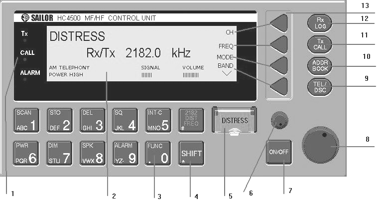
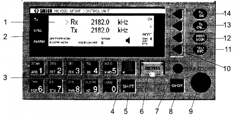
Рис. 16.1. ПВ/КВ радиостанция с ЦИВ
1 — Дисплей, 2 — Индикаторы состояний: Тх — передача, CALL — индикация приема вызова, ALARM индикация приема вызова бедствия,
3 — Панель управления, 4 — Установка частоты бедствия 2182 кГц, 5 — Функциональная клавиша для выбора функций, выделенных желтым цветом,
6 — Кнопка подачи вызова бедствия, 7 — Подстройка частоты, 8 — Включение/выключение, 9 — Регулировка громкости,
10 — Программные клавиши (soft keys), 11 — Переключение режимов телефония/ЦИВ, 12 — Адресная книга,
13 — Формирование ЦИВ, 14 — Вызов электронного журнала принятых ЦИВ
Основные функции
ПВ/КВ радиостанция с ЦИВ НС4500 объединяет в себе однонолосную радиотелефонную радиостанцию и контроллер ЦИВ, заменяя три блока аппаратуры семейства Sailor2000: RE2100, RM2150, RM2151. Радиостанция имеет увеличенный дисплей, более дружественный интерфейс для управления, освоение которого, однако, требует определенных навыков.
На дисплее высвечивается необходимая информация в виде подсказок и вариантов выбора. Оператор должен выбрать тот или иной вариант с помощью программных клавиш 10 справа от дисплея. Их функциональное назначение постоянно меняется и индицируется надписями в правой части дисплея, (аналогичный принцип реализован в банкоматах).
Переключение основных режимов работы радиотелефон/ЦИВ осуществляется клавишей 11 TEL/DSC.
Основные функции по управлению радиостанцией показаны на рисунке.
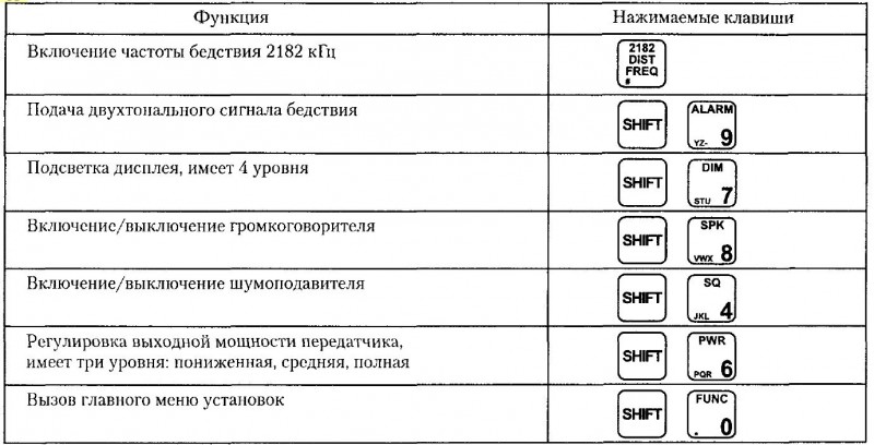
Назначение клавиш радиостанции НС4500
Управление в режиме радиотелефона
Переход в радиотелефонный режим осуществляется клавишей 2182 DIST FREQ или TEL/DSC. В показанном на рисунке примере на дисплее высвечивается номер канала, класс излучения (SSB Telephony — J3E), уровень выходной мощности (MED — средняя), шумоподавитель отключен, уровень входного сигнала — 3 деления, громкоговоритель подключен.
Программными клавишами возможны следующие варианты выбора:
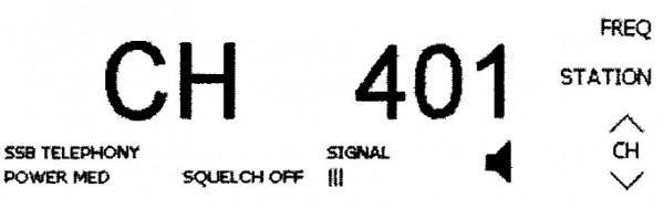 FREQ — показ частот передачи и приема для устаповленного канала,
STATION — выбор береговой станции из памяти,
СН∧, CHv — выбор последующего, предыдущего канала выбранной береговой станции
Для установки номера канала можно также использовать клавиши панели управления.
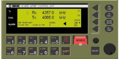
При выборе подменю FREQ верхней программной клавишей на дисплее будут представлены частоты при- ема и передачи данного канала: Rx — частота приемника, Тх — частота передатчика.
Стрелка рядом с изображением Rx указывает на то, что значение приемной частоты может быть изменено с панели управления. Для ввода новой частоты передатчика следует программной клавишей ТХ переместить указатель вниз и ввести значение частоты с панели управления.
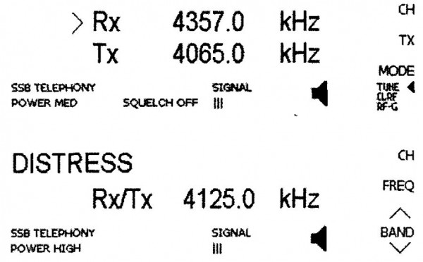 СН — переход к предыдущему меню в форме номера капала,
ТХ — выбор частоты передачи,
MODE — выбор класса излучения,
TUNE, CLRF, RF-G — настройка частоты приемника с шагом 100 Гц, точная подстройка частоты с шагом 10 Гц, регулировка усиления по высокой частоте.
Включение частоты бедствия 2182 кГц осуществляется клавишей 4. Переход к другим телефонным частотам бедствия делают стрелками BANDA и BANDv. На рисунке приведен пример выбора частоты 4125 кГц.
Управление в режиме ЦИВ
Переключение в режим ЦИВ осуществляется кнопкой TEL/DSC. На дисплее индицируются поддиапазоны сканируемых частот. Distress Watch — частоты ЦИВ бедствия, Calling Watch — сканируемые коммерческие ча- стоты. В данном примере сканируются частоты бедствия во всех частотных поддиапазонах 2,4,6,8,12 и 16 МГц, а также коммерческие частоты в поддиапазоне 2 МГц и две частоты в поддиапазоне 12 МГц.
В отличие от аппаратуры Sailor2000, в радиостанции НС4500 имеется один сканирующий приемник частот ЦИВ.
В нижней строке дисплея указывается частота бедствия, которая будет выбрана по умолчанию при быстром вызове бедствия (4207,5 кГц).
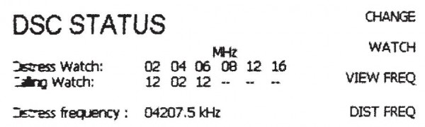 CHANGE — изменение сканируемых коммерческих частот,
WATCH — включение/выключение сканирования коммерческих частот,
VIEW — просмотр сканируемых частот (бедствия и коммерческих).
DIST FREQ — выбор частоты бедствия, используемой по умолчанию при быстром вызове. Рекомендуется устанавливать эту частоту равной 2187,5 МГц, если судно находится в районе А2 В районах A3, А4 рекомендуется устанавливать универсальную частоту для вызова бедствия в KB диапазоне 8414,5 МГц.
 Справа на панели управления расположены кнопки, используемые при работе с ЦИВ RxLOG — вызов электронного журнала принятых вызовов.
Журнал разделен на две части — вызовов с приоритетом бедствия (DISTRESS) и всех остальных (NORMAL)
Содержание вызовов не может быть изменено оператором, вызовы также не удаляются из памяти при выключении питания, а сохраняются в электрически нерепрограммируемой памяти.

TxCALL — формирование вызовов судну, береговой станции или каких-либо других.
 ADDR BOOK — адресная книга для вызова часто запрашиваемых судовых и береговых станций В адресную книгу заносятся MMSI станции и ее частоты.
Станция может быть внесена или удалена из адресной книги оператором.
 TEL/DSC — переключение между режимами телефонии и ЦИВ В этом случае изменяется только индикация режимов.
Радиостанция НС4500 имеет два независимых приемников — для телефонии и ЦИВ, поэтому включение, например, телефонной частоты не означает, что прекращается сканирование частот бедствия ЦИВ.
Частоты ЦИВ бедствия сканируются постоянно при любых режимах работы и индикации радиостанции.
Вызов бедствия
Вызов бедствия
Быстрый вызов бедствия
Быстрый (или неподготовленный) вызов бедствия не содержит информации о характере бедствия и применяется, KOI да обстоятельства не допускают промедления Для подачи неподготовленного вызова бедствия следует открыть защитную крышечку на кнопке DISTRESS и нажать эту кнопку, удерживая ее в нажатом положении в течение 3-х секунд, а затем в течении 2-х секунд отпустить
Тогда в эфир передается ЦИВ бедствия на одной из частот бедствия ЦИВ, которая установлена для выбора по умолчанию со следующими параметрами.
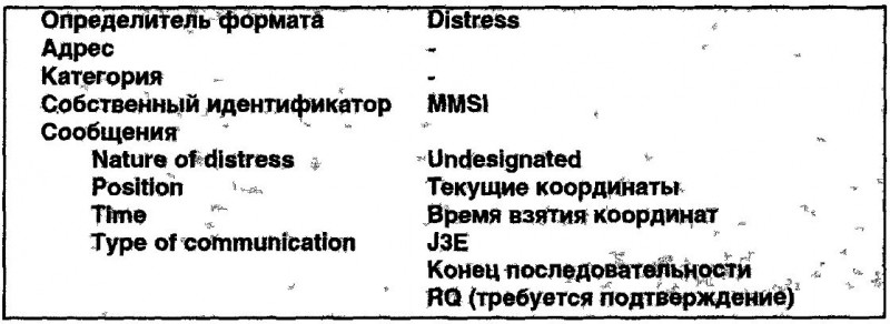
Полный (с указанием характера бедствия) вызов бедствия
Полный вызов бедствия позволяет указать характер бедствия Для формирования полного вызова бедствия следует нажать кнопку TxCALL.
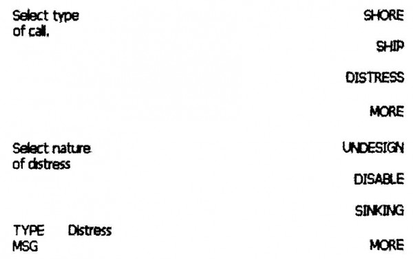 На дисплее появляется предложение выбрать тип вызова Select type of call — SHORE, SHIP, DISTRESS, MORE.
Выбрать тип вызова — DISTRESS
Выбрать характер бедствия, например, SINKING При необходимости выбрать продолжение списка клавишей MORE.
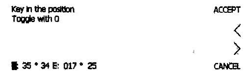
Координаты и время получения координат отображаются автоматически.
При необходимости их можно ввести или отредактировать вручную.
Переключение сторон света следует делать клавишей «О».
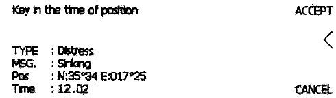
Переход к следующему меню делают клавишей ACCEPT.
В этом меню следует выбрать вид последующей связи:
 SSB TEL — телефония с подавленной несущей J3E,
AM TEL — телефония с полной несущей НЗЕ,
FEC — радиотелекс F1B/J2B,
CANCEL — возврат в предыдущее меню.
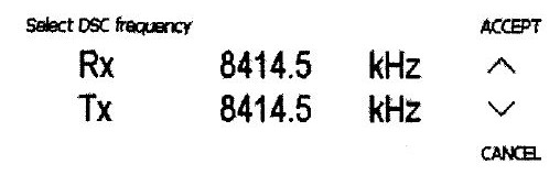
 В следующем меню необходимо выбрать частоту вызова бедствия. Изменение частот делается клавишами v или л. В данном примере выбрана частота 8414,5 МГц. Далее следует подтвердить выбор частоты клавишей ACCEPT.
Для подачи вызова бедствия в эфир с выбранными параметрами надо нажать красную кнопку DISTRESS и удерживать ее в течение 3-х секунд. После этого отпустить кнопку в течение 2 секунд.
На дисплее должна высветиться надпись: Distress call in progress on frequency 8414.5 kHz..
 Вызов бедствия передается блоками из пяти последовательностей. Если вызов не будет подтвержден или остановлен, то повторная передача блока происходит со случайными интервалами 3,5 — 4,5 минуты.
Прием подтверждения
Подтверждает вызов бедствия береговая станция на той же частоте, адресуя его всем судам.
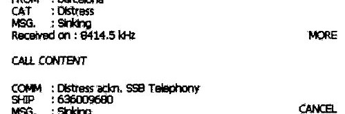
После получения подтверждения о приеме вызова бедствия на дисплее появляется сообщение: Distress acknowledgement received с указанием названия (или MMSI) подтвердившей вызов станции, в данном примере — Барселона. Для просмотра содержания вызова подтверждения DiStreSS acknowledgement следует нажать клавишу VIEW.
 Такое же подтверждение примут другие суда, которые не терпят бедствие.
Содержание вызова подтверждения размещается на двух страницах. Для перехода ко второй странице — нажать клавишу MORE.
CANCEL — переход к следующему меню,
AGAIN — возврат на первую страницу.
В следующем меню индицируется автоматически устанавливаемая частота последующего радиотелефонного обмена — 8291 кГц.
Далее следует передавать сообщение бедствия: «MAYDAY This is…».
Вызовы с обычным приоритетом
Вызовы с обычным приоритетом
Вызов судовой станции
Вызов судовой станции при последующей связи по радиотелефону делают таким образом. Предваритель-но следует ввести рабочую частоту для телефонного обмена в направлении судно-судно, например, 4146 МГц. Выбрать клавишей MODE класс излучения J3E (SSB TELEPHONY). Затем следует сформировать вызов ЦИВ на частоте 2177 кГц.
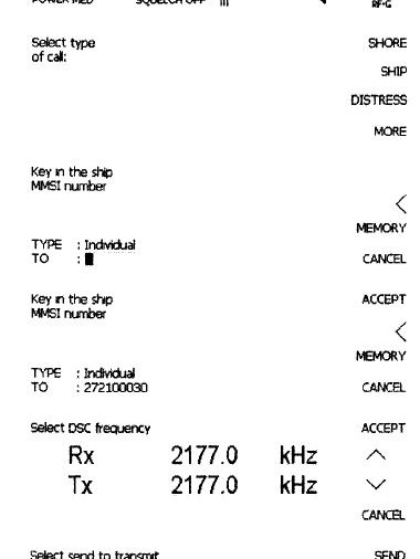 Для формирования вызова нажать клавишу TxCALL. На дисплее появляется приглашение выбрать тип вызова (SHORE, SHIP> DISTRESS или ДРУГОЙ — MORE). Здесь надо выбрать SHIP, нажав соответствующую программную клавишу справа от дисплея.
Далее следует ввести MMSI вызываемого судна, например, 272100030 и подтвердить этот номер нажатием клавиши ACCEPT. Если вызываемая станция записана в адресной книге, то можно вызвать ее номер клавишей MEMORY. Клавишей < можно стереть неверно введенные цифры.
Если номер введен правильно, то — перейти к следующему меню клавишей ACCEPT.
В следующем меню будет предложено выбрать частоту вызова. Для этого стрелкой «вверх» или «вниз» надо найти частоту 2177 кГц.
Перейти к следующему меню клавишей ACCEPT. Параметры вызова представляются на дисплее:
TYPE — тип вызова,
ТО — MMSI вызываемого судна,
СОММ — вид последующей связи,
AD — дополнительная информация, рабочая частота,
ACKN — требуется подтверждение вызова (RQ).
Если вызов сформирован правильно, то следует выбрать SEND, в противном случае можно вернуться на шаг назад выбором CANCEL и внести необходимые изменения в предыдущих меню.
Вызываемое судно должно подтвердить вызов посредством ЦИВ, после чего радиообмен продолжается на рабочей частоте 4146 кГц по телефону.
m/v (название, позывной) вызываемого судна
this is (название, позывной) своего судна
how do you read me? Over
Вызов береговой станции
 Для вызова береговой станции следует нажать клавишу TxCALL. На дисплее появится приглашение выбрать тип вызова. Выбрать — SHORE нажатием соответствующей клавиши справа от дисплея.
Далее следует ввести номер береговой станции, например, 002192000.
Если станция записана в адресной книге, то ее можно вызвать из памяти, нажав клавишу MEMORY.
После ввода номера береговой станции перейти к следующему меню клавишей ACCEPT.
При необходимости автоматического соединения с береговым телефонным абонентом в нижней строке следует набрать полный номер, включающий международный код страны, код го- рода и номер абонента. Переход к следующему меню — нажатием клавиши ACCEPT.
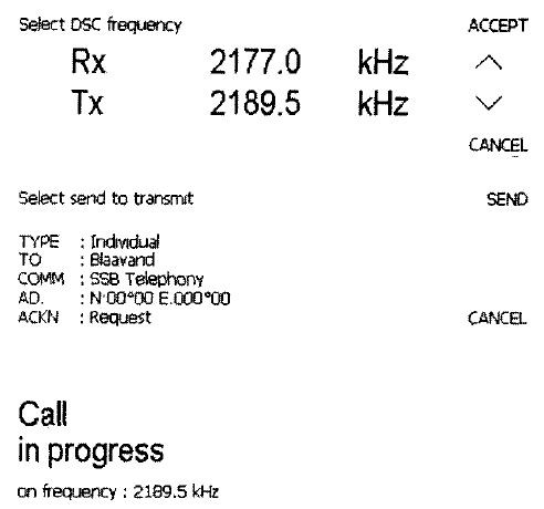 Вызывную частоту 2189,5 кГц и частоту приема подтверждения следует выбрать клавишами ∧ или v. При индикации па дисплее нужной пары частот — перейти к следующему меню.
В этом меню содержатся параметры вызова:
TYPE — тип вызова,
ТО — название береговой станции,
СОММ — вид последующей связи,
AD — дополнительная информация, координаты судна,
ACKN — требуется подтверждение вызова (RQ).
Для передачи вызова в эфир следует выбрать SEND, а для возврата в предыдущее меню — нажать клавишу CANCEL.
Береговая станция должна подтвердить вызов, указав в вызове подтверждения рабочий телефонный канал. После получения ответа срабатывает звуковая сигнализация и автоматически включается назначенный телефонный канал.
Ретрансляция бедствия
Ретрансляция бедствия
Ретрансляция бедствия должна делаться судном, если принят вызов бедствия в KB диапазоне, однако не принято подтверждение или ретрансляция бедствия от береговой станции и не прослушивается радиообмен на соответствующей телефонной частоте бедствия. Ретрансляция должна формироваться вручную по алгоритму расширенного вызова в адрес береговой станции, которая работает в KB диапазоне.
Для формирования вызова ретрансляции следует нажать клавишу TxCALL. На дисплее появляется приглашение выбрать тип вызова. Здесь надо выбрать MORE — продолжение списка типа вызовов.
В следующем меню надо выбрать EXTENDED — расширенный вызов.
Далее — выбрать INDIVIDUAL — индивидуальный вызов.
В следующем меню необходимо выбрать D.RELAY — ретрансляция бедствия.
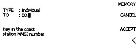
Далее необходимо ввести MMSI вызываемой станции. Для примера введен номер 00219200.
Здесь предлагается ввести номер MMSI судна в бедствии. На <( рисунке введен номер 272100020. При ошибочном вводе какой- либо цифры можно удалить ее стрелкойВ следующем меню выбирается характер бедствия. Список возможных вариантов характера бедствия можно продолжить клавишей MORE.
В этом меню надо указать координаты судна в бедствии.
Ввести время UTC, на которое действительны координаты терпящего бедствие судна.
Выбрать вид последующей связи, например, SSB TEL — одно- полосная телефония, класс излучения J3E.
Стрелкой ∧ или v необходимо выбрать вызывную частоту для ретрансляции. Эта частота не обязательно должна повторять ту, на которой получен вызов бедствия, а выбирается с учетом удаления береговой станции, времени года и времени суток. В примере выбрана частота 8414,5 МГц.
Далее на дисплее приводится содержание вызова. При согласии следует выбрать SEND. В противном случае можно вернуться в предыдущие меню выбором CANCEL.
Are you sure? При согласии надо нажать клавишу YES и удерживать ее 3 секунды.
Передается вызов.
После приема подтверждения от береговой станции (при наличии радиосвязи в выбранном частотном поддиапазоне береговая станция должна подтвердить вызов через 3 минуты) необходимо на соответствующей телефонной частоте 8291 кГц передать сообщение ретрансляции:
MAYDAY RELAY
Blaavand Radio
This is…
Following received from …
Проверки радиостанции
Проверки радиостанции
Контроллеры ЦИВ ПВ/КВ диапазонов должны проверяться:
1) ежедневно путем внутреннего тестирования без излучения в эфир и
2) еженедельно путем тестового вызова береговой станции.
Внутренний тест делается через меню функций:

Далее следует выбрать подменю DSC — MORE — TEST.
Еженедельная проверка выполняется путем тестового вызова береговой станции на частотах бедствия и безопасности: 2187,5 МГц или частотах в KB диапазоне. Однако, тестовый вызов на частоте 2187,5 МГц следует заменять насколько это возможно проверкой на других частотах. Для выполнения теста — нажать кнопку TxCALL На дисплее индицируется предложение выбрать тип вызова. Здесь надо выбрать DBTRESS SHORE.
Далее — ввести MMSI береговой станции, в адрес которой делается вызов. Например, 002192000. Перейти к следующему меню выбором ACCEPT.
В следующем меню — выбрать TEST CALL
Стрелками необходимо выбрать частоту для вызова. Тх — частота передачи, Rx — частота для приема подтверждения от береговой станции. Необходимо уточнить работает ли выбранная береговая станция на этой частоте, например, по Master plan GMDSS.
Для посылки вызова — выбрать SEND. Береговая станция в течение нескольких минут должна подтвердить вызов. Прием подтверждения свидетельствует о правильной работе радиостанции. Данная проверка не предполагает какой-либо дальнейшей связи.
Полное меню установок
Полное меню установок
Меню вызовов доступно после нажатия клавиш SHIFT и FUNC. На дисплее появляется предложение выбрать один из следующих пунктов меню: USER, TELEPHONY, DSC, STATIONS.
Состав меню функций представлен в таблице ниже:
| Меню | Подменю 1 -го уровня | Подменю 2 -го уровня | Параметры |
| USER |
DISPLAY SOUND VERSION PRINT DSC CONFIG |
CONTRAST EARPIECE, ALARM LEVEL |
0-77- наибольший контраст 0-15 Уровень звукового сигнала Просмотр программной версии всех модулей Вкл/Выкл принтера Просмотр аппаратной версии |
| TELEPHONY |
CH PROTECTION TEST |
ADD, DELETE,VIEW |
Добавление, удаление, просмотр каналов пользователя Просмотр кодов защиты трансивера Внутренний тест трансивера |
| DSC |
MMSI ACKN DSC FREQ POSITION TIME TEST LANGUAGE |
ADD, DELETE,VIEW CHANGE CHANGE |
Номер ЦИВ Вкл/Выкл автоматического подтверждения вызовов Добавление, удаление, просмотр частот ЦИВ Автоматический ввод координат GPS Автоматический ввод времени GPS Внутренний тест ЦИВ модема Изменение языка, если допускается |
| STATION |
ADD DELETE VIEW/EDIT |
SHORE, SHIP |
Добавление новой береговой (судовой) станции Удаление станции Просмотр/редактирование станций |
SAILOR
HC4500
MF/HF CONTROL UNIT
Operating Instructions
Distress Calls, see page ii. List of contents, see page 1.
Quick DISTRESS Call
1. If off or STANDBY: press ON/OFF.
2. Open DISTRESS lid.
3. Press DISTRESS until RELEASE is displayed
3 — 2 — 1 —
RELEASE
Then the undesignated distress call will be sent by default on the distress frequency 2187.5 kHz.
Wait for answer!
(The distress call is autorepeated every 5 minutes on the same distress frequency.)
DISTRESS Acknowledgement
Press the DISTRESS button for
3
seconds to transmit
TYPE : Distress
MSG.
: Undesignated
Pos : N57°01 W009°53
Time : 13:01 UTC CANCEL
Awaiting
Automatic
Repetition
Rx 2182.0 kHz
Tx 2182.0 kHz
SSB TELEPHONY
SIGNAL
| | | | | POWER HIGH SQUELCH ON
CANCEL
MODE
TUNE<
CLRF
RF-G
4. Press VIEW to read the contents of call.
5. Press “2182”.
Distress acknowledgement received
FROM: 002191000
6. Lift handset.
ii
Press
Press PTT and say:
DISTRESS
Rx/Tx 2182.0 kHz
AM TELEPHONY
SIGNAL
| | | | | POWER HIGH
“MAYDAY”
“This is”
— the 9-digit identity and the call sign or other identification of the ship,
— The ship’s position,
— The nature of distress and assistance wanted,
— any other information which might facilitate the rescue.
“OVER.”
Release
Listen for answer!
VIEW
ABORT
Read call contents.
CH
FREQ
MODE
BAND
0140
What is What?
13 12 11 10 9
1
2
3 4 5 6 7 8
1.
Display.
2.
Indicator lamps. Condition when lit:
Tx:
CALL:
Transmitting.
DSC (see button 9) call for you received.
ALARM: Alarm call received.
3.
Keyboard.
4.
Shift key. Press and hold for yellow functions.
5.
DISTRESS button. Protected by shield. To use, lift the shield and press for 3 seconds, guided by the text displayed.
6.
Tuning control.
7.
ON/OFF push button.
8.
Volume control.
9.
TEL/DSC function switch.
In TEL mode radiotelephone parameters are shown and selected.
In DSC mode DSC parameters are shown and selected.
10. Opens the ADDR BOOK in DSC mode.
11. Tx CALL: Press to start creating a DSC call.
12. Opens the Rx log over received calls in DSC mode.
13. Soft keys. The function of each key is described in its respective line at the right edge of the display.
iii
Introduction
Congratulations on your new SAILOR HC4500 MF/HF maritime radio telephone with built-in DSC (Digital Selective Calling) system and radiotelex, fulfilling the highest international standards for marine
MF/HF communication and safety procedures. For an explanation of
DSC, see page 2.
Your SAILOR HC4500 MF/HF is a part of the modular system 4000 which also includes a HF single sideband radiotelephone. It has built-in MF/HF telex if connected to a PC and/or a printer. If connected to a GPS or other maritime navigation system it can automatically include the true UTC time and your position in its DSC distress messages.
SAILOR marine equipment is specially designed for the extremely rugged conditions on bord a ship, based on more than 50 years’ experience with all kinds of boats, from small pleasure crafts, over fishing boats working under all climatic conditions, to the biggest ships.
S.P. Radio A/S is one of Europe’s leading manufacturers of maritime radiocommunication equipment — a position which has been maintained by means of constant and extensive product development.
We have a worldwide network of dealers with general agencies in more than fifty countries. All our dealers are specially trained to service all your SAILOR products.
About this manual
This manual is for the daily user of the system. Additionally, it includes a section on the installation procedures, and — on page ii standard distress procedures. We highly recommend you to read
the manual before you start using the equipment.
Please note
Any responsibility or liability for loss or damage in connection with the use of this product and the accompanying documentation is disclaimed. The information in this manual is furnished for informational use only, is subject to change without notice, may contain errors or inaccuracies, and represents no commitment whatsoever.
This agreement is governed by the laws of Denmark.
Document no.: B4500GB0 E/0404
Abbreviations Used in this
Manual
NBPD
PTT
RF-G
Rx
SSB
TEL
Tx
UTC
VHF
GPS
HF
IMO
IRS
ISS
ITU
MF
MMSI
MOM
MSG
ADDR
AGC
AM
ARQ
CLRF
Address
Automatic Gain Control
Amplitude Modulation
Automatic Repetition reQuest
Clarify
CU Control Unit
DIRTLX Direct Telex
DSC
ETSI
FEC
Digital Selective Calling
European Telecommunications Standards Institute
Forward Error Correction
GA Go Ahead
GMDSS Global Maritime Distress and Safety System
Global Positioning System
High Frequency
International Maritime Organisation
Information Receiving Station
Information Sending Station
International Telecommunication Union
Medium Frequency
Maritime Mobile Ship Identification
Just a moment please
Message
Narrow Band Direct Printing
Push-To-Talk
Receiver Frequency Gain
Receive
Single Side Band
Telephony
Transmit
Co-ordinated Universal Time
Very High Frequency
iv
0404
Contents
Quick DISTRESS Call …………………………………………………. ii
DISTRESS Acknowledgement …………………………………….. ii
What Is What? …………………………………………………………… iii
Introduction ………………………………………………………………. iv
About this Manual …………………………………………………….. iv
Abbreviations ……………………………………………………………. iv
MF/HF Fundamental Info ……………………………………………. 2
Propagation of MF and HF Radio Waves. ………………….. 2
Radiotelephony ………………………………………………………. 2
Radiotelex ……………………………………………………………… 2
DSC ………………………………………………………………………. 2
Basic Functions …………………………………………………………. 3
Switching ON/OFF ………………………………………………….. 3
Setting Backlight Level ……………………………………………. 3
Switching Loudspeaker ON/OFF ………………………………. 3
Volume Control ………………………………………………………. 3
Switching Squelch ON/OFF ……………………………………… 3
Setting Transmitter Power Level ……………………………….. 3
Manual Call Functions ……………………………………………….. 4
Telephony Channel Display Functions: ……………………… 4
Frequency Display Functions: ………………………………….. 4
Tuning …………………………………………………………………… 4
Station Display Functions: ……………………………………….. 5
Distress Telephony Frequencies ………………………………. 5
Distress Frequency Display Functions: ……………………… 5
Two-tone Alarm Signal ……………………………………………….. 6
Two-tone Alarm Display Functions: …………………………… 6
Listening for Calls ……………………………………………………… 6
Making a Manual Call …………………………………………………. 6
DSC Main Buttons ……………………………………………………… 7
Calling Watch …………………………………………………………. 8
DSC Display Operation ………………………………………………. 9
Receiving an Individual DSC Call ……………………………… 9
Receiving DISTRESS Call ……………………………………… 10
Calling a SHIP ……………………………………………………….. 11
Calling a SHORE Station ……………………………………….. 12
Address Book ……………………………………………………….. 13
Using Two Control Units ………………………………………… 14
Priority of Control Unit #1 ………………………………….. 14
Control Unit #2 Taking Over the Control ……………… 14
Status Indication ………………………………………………. 14
Responding to Incoming DSC Calls …………………… 14
Power On/Off By Control Unit #2 ……………………….. 14
Interconnecting ………………………………………………… 14
DSC Scanning Frequencies ………………………………. 14
Advanced DSC Calls ………………………………………………… 15
Changing a Function ……………………………………………… 17
The Function Tree ……………………………………………. 18
GMDSS Radiotelex Terminal …………………………………….. 19
Introduction ………………………………………………………….. 19
Keyboard Indicator Lamps ……………………………………… 20
Keyboard Function Keys ………………………………………… 20
Switching On ………………………………………………………… 21
Channel Selection …………………………………………………. 21
Transmitting a Message …………………………………………. 21
Editing a Message ………………………………………………… 21
Receiving a Message …………………………………………….. 22
Installation and Initial Set-up ………………………………….. 22
Printer …………………………………………………………….. 22
Keyboard ………………………………………………………… 22
Modem Set-up …………………………………………………. 22
Example of FEC Transmission ……………………………….. 23
Example of ARQ Transmission to a Coast Statio ………. 23
1
0404
2
MF/HF Fundamental Info
Propagation of MF and HF Radio
Waves.
MF/HF radiocommunications provide a medium and long range service. The 1.6-4 MHz marine band is intended primarily for coastal operation beyond normal VHF communication range. A reliable range of more than 150 nautical miles can be expected in most areas in the daytime, more in the nighttime. Propagation of the radio waves in this band is mainly by ground waves i.e. the waves from the transmitter aerial follow the earth’s curvature to the receiver aerial. The high frequency range 4 — 30 MHz can provide communication for hundreds or even thousands of nautical miles.
The long range is achieved by sky waves reflected from the ionosphere. Propagation of the radio waves depends on a number of factors such as frequency, time of day, time of year, and solar activity. The channels allocated to the maritime mobile service in the
HF range are divided into a number of bands: 4, 6, 8, 12, 16, 18, 22,
25 MHz to allow a suitable frequency band to be selected for communication dependent on distance and time of day.
DSC
DSC (Digital Selective Calling) is an automatic calling system which allows a specific station to be contacted and made aware that a station wishes to communicate with it. In addition to calls to specific stations the system can also be used to call ‘all ships’ and groups of ships and this is of significance for its use for DSC distress alerting.
DSC is an alerting signal only and the communication which follows the call is made on an appropriate frequency band using radiotelephony or radiotelex. The frequencies for DSC distress and safety calling are 2187.5 kHz, 4207.5 kHz, 6312 kHz, 8414.5 kHz, 12577 kHz, and 16804.5 kHz. Calling frequencies for public correspondence with coast stations are arranged in pairs, both international and national frequencies are assigned. In addition the frequency 2177 kHz may be used for ship-to-ship calling.
Radiotelephony
The mode of emission used for telephony transmissions in the marine bands is SSB (single-sideband, J3E). On the international distress frequency 2182 kHz compatible AM (amplitude modulation,
H3E) may be used in addition for communication with non-GMDSS ships. AM mode is used also when receiving broadcasting. The frequencies for radiotelephone distress and safety traffic in the HF bands are 4125 kHz, 6215 kHz, 8291 kHz, 12290 kHz, and 16420 kHz. Working frequencies for public correspondence with coast stations are arranged in pairs for duplex/semi-duplex operation. For the HF bands these channels are allocated numbers by ITU on an international basis. In addition a number of simplex frequencies are available in each band for ship-to-ship communication.
Radiotelex
Marine telex is also referred to as ‘Narrow Band Direct Printing’
(NBDP). Due to the narrow bandwidth of the transmissions, a longer range may be expected compared to radiotelephony. The frequencies for radiotelex distress and safety traffic are 2174.5 kHz, 4177.5
kHz, 6268 kHz, 8376.5 kHz, 12520 kHz, and 16695 kHz. Working frequencies for public correspondence with coast stations are arranged in pairs. For the HF bands these channels are allocated numbers by ITU on an international basis. In addition a number of simplex frequencies are available in each band for ship-to-ship communication.
Basic Functions
Switching ON/OFF
1.
Press the ON/OFF button.
Setting Backlight Level
1.
Press the Shift key followed by the DIM key.
The backlight is changed from zero to maximum in four steps.
Repeat until the desired setting is reached.
Switching Loudspeaker ON/OFF
1.
Press the Shift key followed by the SPK key.
Setting Transmitter Power Level
1.
Press the Shift key followed by the Power Key.
The output power is set to HIGH, MED or LOW.
Repeat until the desired setting is reached.
Volume Control
1.
Rotate the VOL button to adjust the loudspeaker sound volume.
Switching Squelch ON/OFF
(SSB Telephony mode)
1.
Press the Shift key followed by the Squelch key.
When squelch is ON, the receiver output is muted in speech pauses.
3
Manual Call Functions
Telephony Channel Display Functions:
Name of station if selected.
Channel number.
Soft keys
LYNGBY
CH 4 1 8
SSB TELEPHONY
SIGNAL
| | | | | POWER HIGH SQUELCH ON
FREQ
STATION
CH
Switches to Frequency display for viewing or altering frequencies.
Switches to Station display for selection of another station.
Steps to the next lower channel number of the station.
Steps to the next higher channel number of the station.
Squelch setting
Mode of emission
Output power setting
Receive: Signal strength
Transmit: Output power level
A channel number may also be keyed in directly from the keyboard.
If the channel is not allocated to the station selected, the station name will disappear from the display.
Frequency Display Functions:
Receive frequency
Transmit frequency
> Rx 4357.0 kHz
Tx 4065.0 kHz
SSB TELEPHONY
SIGNAL
| | | | | POWER HIGH SQUELCH ON
CH
TX
MODE
TUNE<
CLRF
RF-G
Soft keys
Switches to Channel display and previous channel number.
Moves the arrow to Tx before keying in a Tx frequency.
Steps between SSB telephony, AM telephony and Telex mode.
Steps between Tune, Clarify and RF-Gain tuning functions.
Squelch setting
Mode of emission
Output power setting
Receive: Signal strength
Transmit: Output power level
Rx frequencies may be keyed in directly from the keyboard
Tuning
(Frequency display only)
1.
Rotate the TUNE button to adjust frequency or RF-gain of the receiver.
Functions indicated by arrow in the Frequency display:
TUNE: Frequency tuning in 1 kHz steps (AM), 100 Hz steps (SSB) or 500Hz (Telex).
CLFR: Frequency tuning in 10 Hz steps.
RF-G: Manual RF-gain tuning, AGC off.
4
Station Display Functions:
Name of station
MMSI number of station
STATION TABLE
NAME
CALL SIGN
MMSI NO
TELEX NO
LYNGBY
OXZ
002191000
37383
SELECT
CANCEL
STN
Telex call code
Soft keys
Selects the station and switches to Channel display for choice of channel number.
Returns to Channel display without selecting the station.
Selects previous station.
Selects next station.
Distress Telephony Frequencies
To switch to Distress Frequency display: Press 2182 Distress Freq key.
Distress Frequency Display Functions:
Receive/transmit frequency.
Soft keys
DISTRESS
Rx/Tx 2182.0 kHz
AM TELEPHONY
SIGNAL
| | | | | POWER HIGH SQUELCH OFF
CH
FREQ
MODE
BAND
Switches to Channel display and previous channel number.
Switches to Frequency display.
Selects between AM and SSB mode of emission on 2182 kHz.
Steps to the distress telephony frequency in the next higher band.
Mode of emission
Output power setting
Receive: Signal strength
Transmit: Output power level
The frequencies for distress and safety telephony traffic are
2182 kHz, 4125 kHz, 6215 kHz, 8291 kHz, 12290 kHz, 16420 kHz
5
6
Two-tone Alarm Signal
To switch to the Two Tone Alarm Signal display: Press the Shift key followed by the Alarm key.
Two-tone Alarm Display Functions:
Soft keys
FREQ
Returns to frequency display.
Press the START button
5 seconds to send alarm
TEST
START
Starts test of the alarm signal generator.
Starts transmission of the two tone alarm signal.
Transmission of the two tone alarm signal will continue for 45 seconds, but may be stopped manually by pressing the STOP key in the frequency display. When the alarm signal ceases press the handset key and transmit your distress message by speaking into the handset microphone with a clear and calm voice.
Note: The two tone alarm signal generator is intended for alerting ships not yet equipped with DSC equipment. It may be used only to announce a distress message and primarily on the frequency 2182 kHz in AM telephony mode.
Listening for Calls
Coast stations transmit traffic lists consisting of call signs/names of the ships for which they have traffic.
The traffic lists are sent at specified times and at intervals of typically two hours. They are broadcasted on the normal working frequencies on the coast station. Ships should, as far as possible, listen to the traffic lists transmitted by relevant coast stations. On hearing their call sign they should establish communication as soon as they can do so.
1.
Select the appropriate station.
2.
Select the channel on which traffic lists are transmitted.
3.
Switch loudspeaker on and adjust volume to an appropriate level.
If on HF, traffic lists are transmitted in more frequency bands simultaneously, search for the channel with the best propagation conditions.
Making a Manual Call
Wait until transmission of the traffic list has finished and the channel is free. Call the coast station on the working frequency on which the traffic list was received or as instructed by the coast station.
1.
Hook off the handset.
2.
Press the PTT key on the handset when speaking.
Say:
1. <Called station’s name (3 times)>
2. ‘This is’ <Your ship’s name (3 times)>
3. ‘Over’
3.
Release the PTT key to listen.
4.
When answered:
Follow the instructions from the coast station. The coast station may ask for further identification, information on position and next port of call, and may suggest another working channel for the traffic to follow. If the coast station is not ready to receive traffic immediately it may ask you to wait for a specific number of minutes.
DSC Main Buttons
To switch between the DSC STATUS and telephony displays: press TEL/DSC.
DSC STATUS
CHANGE
WATCH
Distress Watch: 2 4 6 8 12 16 MHz
Calling Watch: 2 2 1 1 4 — MHz VIEW FREQ
Distress Frequency: 2187.5kHz
DIST. FREQ
DSC STATUS display
Soft keys
Changes calling watch frequencies.
Switches between calling watch On/Off
Views watch frequencies.
Changes distress frequency used default for quick distress calls.
LYNGBY
CH 4 1 8
SSB TELEPHONY
SIGNAL
POWER HIGH SQUELCH ON | | | | |
Telephony Display
FREQ
STATION
CH
The button opens to the screen menu where all DSC calls are stored.
In this menu NORMAL or DISTRESS calls, can be read separately and sorted by time.
The button opens the Address book menu.
An addr book call is a complete DSC call added a name. It is possible to transmit, add or delete calls from here.
The button opens to the DSC transmitter menu. From here it is possible to make very easy calls. (SHORE, SHIP) and more complicated calls including special category and tele commands.
The button switches between the DSC STATUS and telephony displays.
The MF/HF set is equipped with two receivers. One for watch on the distress frequencies and one for watch on the public DSC frequencies (calling watch). The calling watch receiver is identical with the receiver of the radio, and therefore it is possible to switch the calling watch on and off. The calling watch is only active in DSC mode, i e.
calling watch is automatically switched off when switching to the TEL screen. But if calling watch is on and the user hooks on the handset, the control unit will automatically switch to the DSC status menu.
7
8
Calling Watch
To switch to DSC screen: press TEL/DSC.
DSC STATUS
CHANGE
WATCH
Distress Watch: 2 4 6 8 12 16 MHz
Calling Watch: 2 2 1 1 4 — MHz VIEW FREQ
Distress Frequency: 2187.5kHz
DIST. FREQ
DSC STATUS display
Active calling watch frequencies.
Soft keys
Changes calling watch frequencies.
Switches between calling watch On/Off
Views watch frequencies.
Changes distress frequency used default for quick distress calls.
Cursor
STATUS
Calling Watch: 02 02 01 01 04 —
Rx Freq: 02187.5kHz
Specified frequency
EXIT
List of watch frequencies
When wanted frequency is selected, press EXIT to return to DSC screen.
Return to DSC screen
Move cursor
Freq. up
Freq. down
0404
DSC Display Operation
Receiving an Individual DSC Call
When calling watch is on, your MF/HF set is constantly scanning the selected DSC channels for incoming DSC calls.
Lift the handset and press PTT to connect to the caller.
Lift HANDSET to connect
Individual call received
OR
VIEW
ABORT
Press VIEW to read out the call.
FROM: 219000012
Press ABORT to return to TEL screen.
CALL CONTENT
Time 10:55:00 13 Okt 97
TYPE: Individual
FROM: 219000012
CAT.: Routine
ACKN: Request MORE
Press MORE to view the second part of call.
Press CONNECT to transmit and set channel.
Press CHANGE to change the acknowledgement.
Select CONNECT to reply call
COMM: SSB telephony
MSG.: No Info
AD.: Freq. RX 2053.0 TX 2053.0
CONNECT
CHANGE
CANCEL
AGAIN
Select send to transmit
TYPE: Individual
TO : 219000012
COMM: SSB telephony
AD.: Freq. RX 2053.0 TX 2053.0
ACKN: Reply
SEND
CANCEL
> Rx 2053.0 kHz
Tx 2053.0 kHz
SSB TELEPHONY
SIGNAL
| | | | | POWER HIGH SQUELCH OFF
CH
TX
MODE
TUNE<
CLRF
RF-G
Press SEND to transmit the reply.
Take the handset and start talking.
9
Receiving DISTRESS Call
When switches on your MF/HF set is constantly scanning all DSC distress channels for incoming DSC distress calls.
Distress call received
FROM: 21900100
VIEW
ABORT
Press VIEW to read out the call.
Press ABORT to return to TEL screen
CALL CONTENT
Time: 08:55:00 22 Sep 97 .
TYPE: Distress
FROM: 219001000
MSG.: Fire
Received on 2187.5 kHz MORE
Press MORE to view the second part of call.
CALL CONTENT
N: 57°01 E:009°52
Time 09:58 UTC
COMM: SSB Telephony
ACK/REPLY
SET UP
CANCEL
Press ACK/REPLY to send distress acknowledgement or distress relay.
In these menus there is a security that makes it impossible to send an acknowledgement by mistake.
Press SETUP to return to the TEL screen with the appropriate radio distress frequency, in this case 2182 kHz.
AGAIN
Press AGAIN to view the first part of call.
If the ship in distress is within a reachable distance press “2182” and listen to the subsequent information.
DISTRESS
Rx/Tx 2182.0 kHz
AM TELEPHONY SIGNAL
POWER HIGH SQUELCH OFF | | | | |
CH
FREQ
MODE
BAND
10
Calling a SHIP
Press Tx CALL
Select type of call:
SHORE
SHIP
DISTRESS
MORE
Select a SHIP call.
Key in the nine digit MMSI number of the wanted ship.
Key in the ship
MMSI number
ACCEPT
<
MEMORY
TYPE: Individual
TO : 210215456 CANCEL
The current telephony frequency is included in the call, and this frequency is used as working frequency for the following radio communication.
Accept the number.
A sub menu where a pre-programmed ship can be selected.
Select DSC frequency
Rx 2177.0
kHz
Tx 2177.0
kHz
ACCEPT
CANCEL
SEND Select send to transmit
TYPE: Individual
TO : 210215456
COMM: SSB telephony
AD.: Freq. RX 2053.0 TX 2053.0
ACKN: Request CANCEL
Select the frequency on which the call is transmitted.
Select SEND to transmit the call.
You first see the messages “Call in progress” and then “Waiting for acknowledgement”
Wait for answer
If the ship answers, see page 8 Receiving an Individual DSC call.
11
Calling a SHORE Station
Press Tx CALL
Select type of call:
SHORE
SHIP
DISTRESS
MORE
Select a SHORE call.
Key in the nine digit MMSI number of the wanted coast station.
Key in the coast station MMSI number
ACCEPT
<
MEMORY
TYPE: Individual
TO : 002191000 CANCEL
If the SHORE station supports the possibility of including a telephone number, the telephone number can be keyed in followed by ACCEPT.
Key in the phone number
TYPE: Individual
TO : LYNGBY
_
ACCEPT
<
TEST CALL
CANCEL
Select DSC frequency
Rx 8049.0
kHz
Tx 8049.0
kHz
ACCEPT
Select send to transmit
CANCEL
SEND
TYPE: Individual
TO : LYNGBY
AD.: No info
ACKN: Request CANCEL
Note that when calling a coast station, it is always the coast status that selects the working frequency for the following communication.
12
Accept the number.
A sub menu where a preprogrammed station can be selected.
Select ACCEPT to make a call directly to the shore station and talk with a person there if no phone number is keyed in.
Select TEST CALL to make a test call to the coast station.
Select the frequency on which the call is transmitted.
Select SEND to transmit the call.
You first see the messages “Call in progress” and then “Waiting for acknowledgement”
Wait for answer
If the coast station answers see page 8 Receiving an Individual DSC call.
Address Book
This MF/HF set is designed with self explaining menues.
The four soft keys on the right side of the display refer to the display text.
Open the addr book menu.
Lower left side of the display is the data area.
Upper left side of the display is used for text instructions
Use ^, or keyboard to search in addr book
Ms Sunrise
TO : 219222222
MSG : No info
Select ADD to make a new call
ACCEPT
NAME
MORE
Right side shows the function of the soft keys.
Accepts the data.
Go to the next screen on the same subject.
ADD
DELETE
CANCEL
AGAIN
One step back.
Go to the first screen on the same subject.
13
Using Two Control Units
You can connect two control units to the system. However, it can only be controlled by one control unit at a time.
If for instance control unit #2 has sent an individual DSC call, control unit #2 is to receive and respond to the acknowledgement call that may follow.
If a call comes in when both control units are in the DSC Status
Menu, and therefore not active, both control units are to receive and respond to the call.
Priority of Control Unit #1
Control unit #1 has the highest priority, i.e. you can always control the system by means of control unit #1 – even if control unit #2 has initiated a distress call.
Control Unit #2 Taking Over the Control
When control unit #1 is in the DSC Status Menu, control unit #2 can take over the control of the system by leaving the DSC Status Menu.
When control unit #2 returns to the DSC Status Menu, the control is automatically given back to control unit #1.
Status Indication
Control Unit #1:
When control unit #2 controls the system, the display of control unit
#1 shows what activity is taking place. The following read-outs may appear:
•
”
OCC by unit 2 sending Distress alert” means that control unit #2 is transmitting a distress call, or awaiting automatic retransmission.
•
“ OCC by unit 2 sending DSC call” means that control unit #2 is transmitting an ordinary DSC call.
•
“ OCC by unit 2 using DSC functions” means that control unit
#2 is in a DSC menu without transmitting a call.
•
“
OCC by unit 2 using Radio functions” means that control unit #2 is not in a DSC menu.
Control Unit #2:
The display of control unit #2 always shows when the system is busy. When the system is not busy, the display shows the DSC
Status Menu.
If control unit #2 tries to take over the control, but is not allowed to do so, this is indicated by both a sound and the display read-out “ OCC by unit 1”.
Responding to Incoming DSC Calls
When a call comes in, only the active control unit – i.e. the one that controls the system at the moment – is to respond.
Power On/Off By Control Unit #2
Power On
You can turn on the whole system by means of control unit #2. If the display shows the words “ Unit switched off”, and the on/off button is pressed, what happens depends on whether or not control unit #1 is controlling the system at the moment: a) If control unit #1 is controlling the system, this will be indicated by the display of control unit #2.
b) If control unit #1 is not controlling the system, control unit #2 will start up in the DSC Status Menu.
When the whole system is off, it makes no difference which control unit turns it on.
Power Off
You cannot turn off the whole system by means of control unit #2.
When you press the on/off button, only control unit #2 is turned off.
The display will then show the words “ Unit switched off”.
Interconnecting
When you have received a DSC call, including working frequency, it is possible to transfer the system control from control unit #1 to control unit #2. To do so, in the Frequency menu, key: “ Shift” + “INT-
C/InterCom”.
When a DSC call is transferred from control unit #1 to control unit #2, the right working frequencies are maintained.
If the handset of control unit #2 is not lifted within five minutes, the control automatically returns to control unit #1.
DSC Scanning Frequencies
You cannot change the DSC scanning frequencies by means of control unit #2. The scanning frequencies used when in the DSC
Status Menu of control unit #2 are the same as if in the DSC Status
Menu of control unit #1.
If control unit #1 changes the DSC scanning frequencies, that information is passed on to control unit #2. Therefore, if control unit
#2 is given the control, and starts scanning, the same scanning frequencies are used.
14
Advanced DSC Calls
Extended DSC calls make it possible for you to control the call completely within the international rules, including the possibility of sending data or fax from optional equipment connected to your MF/
HF set.
To start an extended call, select EXTENDED as the ‘Type of call’ in the Tx menu below, and then continue in the Extended calls menu on next page.
If you have selected an INDIVIDUAL Ship, GROUP, or Group AREA call, all your options are the same after having selected the address.
Please observe the international rules for the rights to forward
DISTRESS RELAY calls.
Tx menu. Enter correct data instead of examples shown in italics::
Type of call Address
SHORE Shore:
001234567
Shore
→
Phone:
or from
ADDR.BOOK
SHIP
123456789
Options Other data transmitted
No info: Call shore station Routine — SSB telephony — No Info
98765432: Call Phone No.
Test call
(none)
Routine — SSB telephony — <Phone number>
Safety — Test — No info
Routine — SSB telephony — No Info — Work frequency
LAST CALL
DISTRESS
EXTENDED
Repeat the last call made.
UNDESIGNATED
DISABLE
SINKING
LISTING (CAPSIZE)
GROUNDING
COLLISION
FLOODING
FIRE
ABANDONING
PIRACY
MAN OVER BOARD
EPIRB
(See next page)
Position
UTC time for position
… to be entered manually if not obtained from e.g. a GPS.
Telecom 1
SSB telephony
AM telehony
FEC
?
Ackn.
Yes
Yes
Yes
15
EXTENDED Tx call started from “EXTENDED” in the table on the previous page. Enter correct data instead of examples shown in italics:
Type of call Address
INDIVIDUAL
Shore: 001234567
Shore phone:
GROUP
G.AREA
Ship: 123456789
012345678
N:57° d02°
Options Category Telecom 1
No info: Call shore station Routine
98765432: Call Phone No. Routine
Telecom 2
SSB telephony No info
SSB telephony No info
SSB telephony No info
AM telephony MEDICAL
POLLING AIRCRAFT
Add. msg.
Ackn.
Yes
No info
Position
Work.
frequency
W:009° d03°
The data in the example gives the area:
N:55..57°
W:6..9°
No info
FAX
ARQ
FEC
TTY RX
TTY
TAPE
MORSE
SHIP
POSITION
DATA
ROUTINE
URGENCY
DISTRESS
SAFETY
BUSINESS
Unable to comply
No info
ALL SHIPS
DISTRESS RELAY
DISTRESS ACK
Type of address
Address
ALL SHIPS All ships
INDIVIDUAL 001234567
Type of address
Address
ALL SHIPS All ships
Ship in distress
Distressed ship’s MMSI
DISTRESS
SAFETY
URGENCY
Distress relay
UNKNOWN
KNOWN 123456789
Distressed ship’s MMSI
Distress ack
123456789
Same as above
As for
DISTRESS in table Tx
Call
As for
DISTRESS in table Tx
Call
As for
DISTRESS in table Tx
Call
As for
DISTRESS in table Tx
Call
MMSI address rule:
Shore station numbers start with 00, group numbers start with one 0, ship numbers start with a digit 1-9.
V21
V22
V22 BIS
V23
V26
V26 BIS
V26 TER
V28 TER
V32
No reason
Congestion
Busy
Queue
Station Barred
No operator
Temporary engaged
Equipment
not
No channel
No mode
No info
Same as above
Work.
frequency
As for
DISTRESS in table Tx
Call
As for
DISTRESS in table Tx
Call
Yes
No
No
16
Changing a Function
There are a large number of function settings available, selectable from a function tree, see the next page. This chapter only deals with the principles of how to use the function tree.
An example:
Changing the Display Contrast
Press SHIFT and FUNC to enter function menu.
Select function or group of settings
Select type of general user functions
^
Use ^, to change value
Contrast:
6
USER
TELEPHONY
DSC
MORE
DISPLAY
SOUND
VERSION
MORE
ACCEPT
CANCEL
Select the USER functions.
Select DISPLAY.
Use ^ and v to change the contrast value.
17
The Function Tree
Menu
User
Menu
Telephony
Submenu Level 1
Display
Sound
Version
Print DSC
Config
Submenu Level 1
CH
Menu
DSC
Menu
Station
Protection
Test
Submenu Level 1
MMSI
ACKN
DSC Freq
Position
Time
Test
Language
Submenu Level 1
Add
Delete
View / Edit
Submenu Level 2
Contrast
Earpiece level
Alarm level
Submenu Level 2
Add
Delete
View
Submenu Level 2
Add
Delete
View
Change
Change
Submenu Level 2
Shore
Ship
Parameters
0 to 7. High Contrast = 7
Attenuation Level 0 — 15
Attenuation Level 0 — 15.
SW versions for all modules
Printer On/Off
HW configuration
Parameters
Add new user ch
Delete user ch
View ch
Read Transceiver protection codes
Self test TU module
Parameters
The MMSI number of the unit
Auto ackn on request On/Off
Add new DSC call/receive freq
Delete DSC call/receive freq
View DSC call/receive freq
Automatic if connected to a GPS
Automatic if connected to a GPS
DSC modem self test
Change language if allowed
Parameters
Add new shore station
Add new ship station
Delete station
View stations or Edit stations
Options: System settings.
For authorized service personnel only.
18
GMDSS Radiotelex Terminal
Introduction
The GMDSS Radiotelex Terminal is an option used for handling transmission/reception of telex messages over radio. The terminal consists of a printer and a keyboard, connected to the transceiver control unit which provides the interface to the DSC/telex modem located in the transceiver unit. The keyboard is equipped with an affixed template for function keys and indicator lamps.
The GMDSS Radiotelex Terminal was designed in accordance with relevant IMO, ITU and ETSI recommendation/specifications and has been approved for shipboard installations to be operating within the Global Maritime Distress and Safety System.
It supports world-wide ship-to-ship, shore-to-ship and ship-to-shore communication by utilizing the radiotelex protocols described in
ITU- Rec. 625 to overcome the deficiencies of the HF medium. In case of two-way communication an ARQ (Automatic Repetition reQuest) algorithm for error correction is thus used, and when sending to more than one station an FEC (Forward Error Correction) algorithm is used.
To facilitate error detection the source text consisting of 5-bit telex characters is coded to a constant weight (3/4 ratio of mark and space bits) 7-bit code. In FEC mode the message is sent in time diversity i.e. each character is sent twice with a time interval by interleaving the original character stream with a delayed version of itself. The receiving station thus has two chances to receive the character correctly. If both are in error a ‘*’ is printed. FEC broadcast calls are used for sending collective messages to several stations simultaneously. A special class of FEC allows selective calling by means of call codes. The message is transmitted in inverted format and only receiving stations with the correct call codes will receive the message.
ARQ operation involves two stations. The information sending station (ISS) sends the information in blocks of 3 characters and listens in the interval between the blocks for an acknowledgement character to be received from the information receiving station
(IRS) indicating whether or not the latter has detected any erroneous character(s) in which case the block will be repeated by the ISS. Both the stations involved in a communication session may initiate an OVER sequence to change the direction of information flow or a BREAK sequence to terminate the connection. The station which initiates the connection becomes the
‘master’ station by transmitting the call signal of another station after going from ‘standby’ to ‘phasing’ state. The called station becomes the ‘slave’. When it recognizes its own call signal it will also leave ‘standby’ and enter ‘phasing’ state by transmitting an appropriate control character. After having verified the other station’s identity both stations will proceed to ‘traffic’ state and start exchanging messages. If the quality of the radio link deteriorates resulting in a large number of block repetitions, both stations will automatically advance to the ‘rephasing’ state, in which the ‘master’ station tries to call the ‘slave’ again, as it did in the ‘phasing’ state, without any of them terminating the connection now under re-establishment. Both 9 digit and 5/4 digit call signals are supported and the corresponding switching between the new protocol (ITU-R M. 625) and the old ITU-
R M. 476 is automatically performed.
19
Keyboard Indicator Lamps
‘Standby’ Steady light indicates that the terminal is ready.
Flashing light indicates that the printer is off or out-of-paper or the modem is busy/ inhibited. Telex mode must be selected in the frequency display of the CU.
‘Tx’
‘Called’
Steady light indicates that a radiotelex transmission is in progress.
Flashing indicates phasing, rephasing
(‘Called’ diode flashes as well) or repetitions.
Steady light indicates that a radiotelex call has been detected and reception is in progress.
Flashing indicates rephasing (‘Tx’ diode flashes as well).
Keyboard Function Keys
Select CH (F1): Sets the frequencies of the transceiver in accord with the selection of ITU coast station or ITU intership channel and the entry of ITU channel number.
Call FEC (F2):
Call ARQ (F3):
Edit Mesg (F4):
Send Mesg (F5):
WRU (F6):
DE (F7):
Over (F8):
Initiates an FEC transmission.
Responds to the printer with a choice of broadcast or selective FEC. Selecting selective FEC requires entry of call code, before the transmission begins.
Initiates an ARQ call. Responds by printing
‘ARQ call code?’, expecting the call code of the station to be called to be typed. Upon carriage return (¬ Enter), the ARQ transmission begins.
Edits a message to be transmitted later.
Transmits (prints in Standby) the edited message.
Requests the other station to transmit its answer-back code.
Transmits own answer-back code, see
Modem Set-up also.
Changes the direction of an ARQ connection.
Break (F9):
On/Off (F10):
Terminates a connection.
Responds by printing ‘Breaking connection’.
If pressed during transmission of an edited message this is terminated. Press once more to terminate the connection.
Switches the GMDSS telex On/Off. The
‘Standby’ keyboard indicator lamps gives out steady light when the switch on process is finished. Call codes and abbreviated ID are printed.
2174.5 kHz (Ctrl+F1) Selects the distress frequency 2174.5 kHz.
4177.5 kHz (Ctrl+F2) Selects the distress frequency 4177.5 kHz.
6268 kHz (Ctrl+F3) Selects the distress frequency 6268.0 kHz.
8376.5 kHz (Ctrl+F4) Selects the distress frequency 8376.5 kHz.
12520 kHz (Ctrl+F5) Selects the distress frequency 12520.0 kHz.
16695 kHz (Ctrl+F6) Selects the distress frequency 16695.0 kHz.
Bell (Ctrl+F7) Transmits Bell character.
20
Switching On
Press F10 and switch on the printer (The ‘Select’ printer indicator must be on). Select telex mode in the Frequency Display of the control unit. If the modem is used for DSC or is inhibited because the transceiver is used for telephony, the Standby keyboard indicator lamp is flashing to indicate that the terminal is not ready.
The ‘Standby’ keyboard indicator lamp shines steady light when connection to the telex modem is established and the following text appears on the printer (example):
5-digit call code: 12345
MMSI number: 123456789
Abbreviated ID: abcd
Channel Selection
Press F1. The printer responds by printing:
‘ITU Coast station / interShip channel (C/S)?:
After pressing ‘C’ or ‘S’ as desired the channel number is requested and must be typed in. The validity of the channel number is checked.
If the channel number does not exist this is indicated.
If the channel number exists the corresponding frequency pair is printed and the transceiver is set accordingly.
The radiotelex distress and safety frequencies may be selected by simultaneously pressing ‘Ctrl’ and the appropriate function key F1 to
F6.
Transmitting a Message
Before calling, it must be ensured that the transmission will not interfere with transmissions already in progress. Switch the loudspeaker on and listen in on the selected channel.
Press Call FEC or Call ARQ as desired and enter the call code of the station to be called. For transmission to two or more stations the
FEC mode should be used. For communication between two stations the ARQ mode should be used.
Before any message can be sent, wait until the connection has been established, or in the case of FEC until the opening phase sequence has been transmitted. When the system is ready for message transmission a “>” is printed and the Tx keyboard indicator shines steady light.
After a successful ARQ connection has been established, answerback codes may be exchanged by pressing the
WRU and DE keys. A message may now be transmitted by pressing carriage return (¬
Enter) followed by the message to be transmitted, either typed in directly from the keyboard, or recalled from the text memory by pressing the Send Message key. Communication with coast stations must be in accordance with the procedures specified by the particular coast station. Where the appropriate facilities are provided by the coast station, traffic may be exchanged with the land telex network.
Having completed the transmission, an exchange of answer-back codes should take place. The radio connection is terminated by pressing the
Break key.
Editing a Message
A text memory is used for storing a message for later transmission.
The message can be transmitted one or more times. The message is printed out when the Send Message key is pressed.
A message can be entered into the text memory after pressing the
Edit Message key in standby mode. Any previous contents of the text memory are printed out then and may be supplemented, corrected or deleted.
Editing keys:
Edit Mesg(F4)
Backspace
Selects edit-mode and prints the contents of the text memory.
Deletes the last character keyed in if it has not been printed.
Insert
Delete followed by line number, selects a line.
The contents of the line, if any, are printed.
Text may be added or deleted.
Deletes the last word of the line
Deletes message (after confirmation) if pressed after Edit (F4).
Line numbers (10, 20, etc.) are added automatically when typing the message.
21
Receiving a Message
Reception is possible whenever the terminal is on, indicated by steady light in the ‘Standby’ keyboard indicator. The radio must be set to telex mode and to the desired working channel.
When a call is detected the ‘Call’ keyboard indicator lamps turns on.
In case of paper-out during reception the connection is terminated.
The process may be repeated if ‘N’ is pressed; the modem set-up mode is left if ‘Y’ is pressed.
The answer back of the modem is generated by combining the 5-digit call code or MMSI number, the abbreviated ID and an ”x” e.g.:
12345 abcd x or
123456789 abcd x
Installation and Initial Set-up
Printer
The terminal uses an OKI Microline 280 parallel interface dot-matrix printer with roll paper stand, please refer to the operation guide delivered with the printer. The printer should be connected to the printer socket at the rear of the control unit by means of the parallel interface cable included with the printer. The printer is equipped with a special firmware which allows the paper to be scrolled up so the current line can be read in printing pauses, and scrolled back down when printing continues. The firmware version can be checked by performing a selftest: Disconnect the parallel interface cable. Press the LF button (line-feed) while switching the printer on. When light comes on in the indicator lamps, release the LF button. The printer version is now printed followed by a test print-out. The version must be: F/W 01.01 S33-67-7145.
Keyboard
The keyboard is a Cherry 1800 PC/AT compatible keyboard. The self-adhesive keyboard template delivered with the equipment must be mounted on the keyboard: Remove the protective paper. Carefully place the template around the function keys and indicator lamps so the latter are fully visible.
Modem Set-up
Modem set-up mode is selected automatically when turning the
GMDSS telex on if no call codes are valid or if the abbreviated ID is not valid. To change a valid set-up, a factory resetting of the modem must be performed.
The 5-digit call code, the MMSI number and the abbreviated ID allocated to the station may then be entered in turn. To leave a setting unchanged just press ‘¬ Enter’. Otherwise key in a new setting and press ‘¬ Enter’. The next item is then printed. After the last item follows:
Accept settings (Y/N) ?
22
Example of FEC Transmission
Assuming the GMDSS telex terminal is in Standby and the radio is set up to telex mode and to the desired frequencies following a DSC
Distress alert call, proceed as follows:
Press Call FEC. The printer responds by printing:
Broadcast FEC or Selective FEC (B/S)?
Press the ‘B’ key. The printer responds by printing:
Broadcast FEC call 1997-10-05 12:30:23, Tx 2174.5 kHz
The transmission starts, the ‘Tx’ keyboard indicator starts flashing and the control unit display indicates that the transmitter is delivering
RF output to the aerial. When the phasing sequence (including carriage return, line feed, letter shift) has been transmitted the ‘Tx’ lamp shines steady light and the printer responds by printing:
>
The communication to follow must be in accordance with the procedures specified for distress traffic and contain:
•
the distress signal ‘Mayday’;
•
the words ‘this is’;
•
the 9-digit identity and call sign or other identification of the ship,
•
the ship’s position if not included in the DSC distress alert;
•
the nature of distress;
•
any other information which may facilitate the rescue.
The connection is terminated by pressing the Break key. After a few seconds transmission stops, the Standby keyboard indicator lamp goes on and the terminal is ready to receive.
Example of ARQ Transmission to a
Coast Station
When the GMDSS telex terminal is on, indicated by the ‘Standby’ keyboard indicator lamp, and the radio is set up to the desired working channel (and, if requested by the coast station, free signal can be heard in the speaker), press the
Call ARQ key.
The printer responds by printing:
Enter ARQ call code:
Type in the call code, e.g.: 0832
If ok, press carriage return (<- Enter), (otherwise press Call ARQ again).
The printer responds by printing:
ARQ 0832 call, 1997-10-05 12:45:10,
The transmission starts, the ‘Tx’ keyboard indicator lamp starts flashing and the control unit display indicates that the transmitter is delivering RF output to the aerial. When successful connection has been established the ‘Tx’ keyboard indicator lamp shines steady light and the printer responds by printing:
>
The exchange of answer-backs is initiated by the coast station. The answer-back code of the called station is printed:
0832 AUTOTX DK followed by a go ahead indication and a traffic direction change:
GA+?
If direct connection with a land telex subscriber is wanted, type: dirtlx54321+ where 54321 is the telex number of the subscriber. The coast station responds with:
MOM
Dialling follows automatically, and simultaneously the number selected is sent to the ship:
54321
When the connection is ready, the time, answer-back, “via Lyngby
Radio” and “MSG+?” is sent:
97-10-5 12:46
54321 ZYXW VIA LYNGBY RADIO
MSG+?
23
Send own answer-back by pressing the DE key:
123456789 abcd x
The message is now transmitted by pressing carriage return (¬
Enter) followed by the message to be transmitted, either typed in directly from the keyboard, or recalled from the text memory by pressing the MESSAGE key: this message is typed in directly from the keyboard or recalled from the text memory.
Having completed the transmission, the answer-back code of the subscriber is requested by pressing the WRU key: x
54321 ZYXW and own answer-back is sent by pressing the DE key:
123456789 abcd x
To disconnect the land line type: kkkk
The coast station responds with:
Time: 97-10-5 12:48
Ship: 123456789 ABCD X
Subscr: 54321
Duration: 1.3
GA+?
A new land line connection may be made or the radio connection terminated by pressing the Break key. After the end-of-communication procedure the transmission stops and the ‘Tx’ keyboard indicator goes off.
24
1
2
1. Display.
2. Indicator lamps. Condition when lit:
Tx:
Transmitting.
CALL:
DSC (see button 9) call for you received.
ALARM:
Alarm call received.
3. Keyboard.
4. Shift key. Press and hold for yellow functions.
5. DISTRESS button. Protected by shield. To use, lift the shield
and press for 3 seconds, guided by the text displayed.
6. Tuning control.
7. ON/OFF push button.
8. Volume control.
3
4
5
6
9. TEL/DSC function switch.
In TEL mode radiotelephone parameters are shown and
selected.
In DSC mode DSC parameters are shown and selected.
10. Opens the ADDR BOOK in DSC mode.
11. Tx CALL: Press to start creating a DSC call.
12. Opens the Rx log over received calls in DSC mode.
13. Soft keys. The function of each key is described in its respective
line at the right edge of the display.
13
12
11
7
8
10
9
iii