Предупреждение
Определение безопасности: предупреждения о безопасности в данном руководстве делятся на следующие два типа:
Опасность: опасность, вызванная тем, что операция не в соответствии с требованиями может привести к серьезным травмам, даже к смерти человека;
Опасность: вызванная тем, что операция не в соответствии с требованиями может привести к травмам средней тяжести или незначительным травмам.
Пожалуйста, внимательно прочитайте эту главу, когда пользователь устанавливает, отлаживает и обслуживает эту систему, должен работать в соответствии с необходимыми предупреждениями о безопасности в содержании этой главы. Любые повреждения и потери, вызванные работой, которая не соответствует оговоренным требованиям, не относятся к нашей компании.
Схема подключения преобразователя
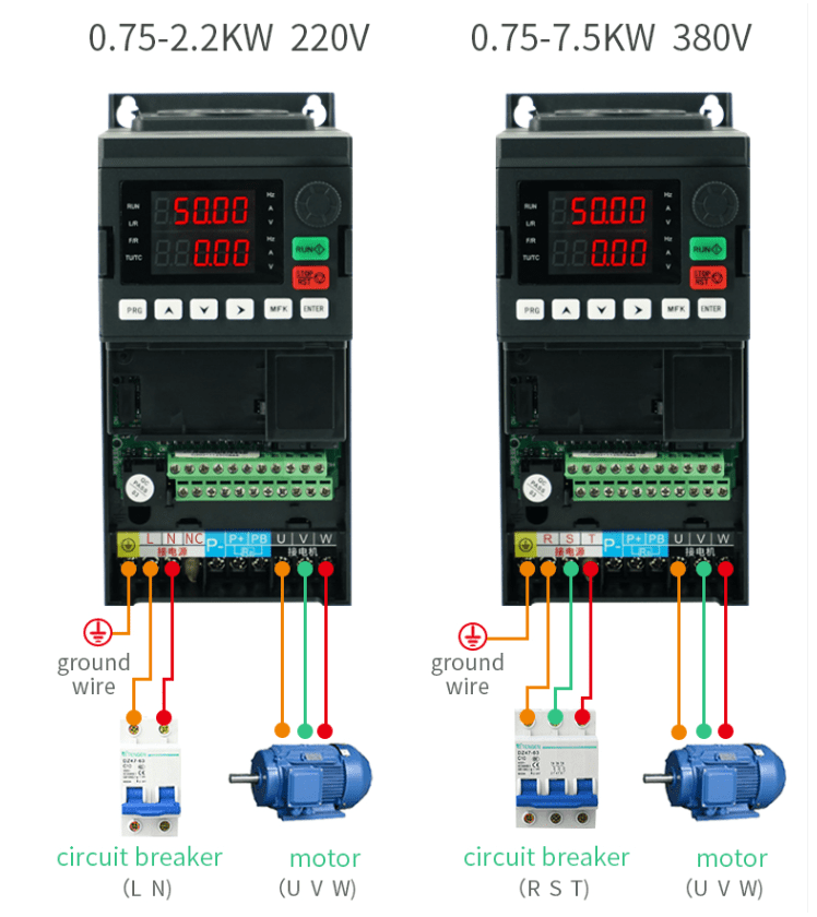
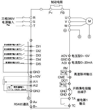
Таблица параметров
Примечание: Полный список параметров доступен в файле в конце страницы!
| Код функции | Название | Диапазон настройки | Заводское значение | EDC Адрес EDC |
| P0-01 | Выбор источника заказа | 0 no датчик скорости векторное управление 2 V/F V/F контроль | 2 | 61441 |
| P0-02 | Выбор источника заказа | 0 LED панель прохода заказа (светодиод потух) 1LED Терминальный проход заказа (светодиодное освещение) 2LED Проход для заказа связи (светодиод мигает) |
0 | 61442 |
| P0-03 | Выбор источника о с н о в н о й частоты | 0P0-08, UP/DOWN Настройка цифр (предустановленная частота P0-08, UP/DOWN может быть изменена, не запоминается при выключении питания) 1P0-08, UP/DOWN Настройка цифр (предустановленная частота P0-08, UP/DOWN может быть изменена, память при выключении питания) 2 Все 3 AI2 4 AI3 устройство электрического потенциала клавиатуры 5 HDI X5 Настройка импульса HDI (X5) 6 умножение порядков секций 7PLC простой и легкий PLC 8 PID 9Настройка связи | 4 | 61443 |
| P0-04 | Выбор источника вспомогательной частоты | P0-03 X То же, что и P0-03 (выбор источника основной частоты X). | 0 | 61444 |
| P0-05 | Y Выбор диапазона Y источника частоты при наложении | 0 против максимальной частоты 1 X напротив источника частоты X | 0 | 61445 |
| P0-06 | Y Частота выбор диапазона Y источника, когда | 0% 150% | 100% | 61446 |
| The блок: выбор источника частоты 0X основной источник частоты X 1: основная и вспомогательная арифметика (арифметический метод определяется по декаде) 2X Y Декада: основная источник частоты X и источник вспомогательной частоты Y сдвиг 3X main частота | ||||
| P0-07 | Выбор метода наложения источника частоты | источник X и сдвиг результата основной/вспомогательной арифметики 4Y Assist источник частоты Y и сдвиг результата основной/вспомогательной арифметики Decade: источник частоты арифметическое отношение основной/помощник 0 + основной + помощник 1- главный помощник 2 максимальное значение из обоих 3 минимальное значение из обоих 4x main x assist | 00 | 61447 |
| P0-08 | Частота предустановки | 0.00Hz максимальная частотаP0-10 | 50.00Hz | 61448 |
| P0-09 | Направление движения | 0 направление согласования 1 противоположное направление | 0 | 61449 |
| P0-10 | Максимальная частота | 50.00Hz 320.00Hz (P0-22=2) 50,0 Гц 3200,0 Гц (P0-22=l) | 50.00Hz 50,0 Гц | 61450 |
| P0-11 | Источник частоты верхнего предела | 0 P0-12 setting 1 All 2 AI2 3 электрический потенциал клавиатуры 4 HDI HDI установка импульса 5 настройка телекоммуникаций | 0 | 61451 |
| P0-12 | Предельная частота подъема | P0-14P0-10 Предельная частота P0-14~Максимальная частота P0-10 | 50.00Hz | 61452 |
| P0-13 | Up предельное отклонение частоты | 0.00Гц Максимальная частота P0-10 | 0,00 Гц | 61453 |
| P0-14 | Предельная частота падения | 0.00ГцP0-12 Предельная частота P0-12 | 0,00 Гц | 61454 |
| P0-15 | Частота несущей волны | 0.5KHz16.0KHZ | 0,00 Гц | 61455 |
| P0-16 | Частота несущей волны регулируется вдоль с температурой | 0 Нет 1 Да |
0 | 61456 |
| P0-17 | Время ускорения 1 | 0с 65000с (P0-19=0) 0.0с 6500.0с (P0-19=l) 0.00s 650.00s (P0-19=2) | Подтверждение модели | 61457 |
| P0-18 | Время замедления 1 | 0с 65000с (P0-19=0) 0.0с 6500.0с (P0-19=l) 0.00s 650.00s (P0-19=2) | Подтверждение модели | 61458 |
| P0-19 | Ускорение и умеренная единица времени | 0согласное направление 1противоположное направление | 0 | 61459 |
| P0-21 | Помощь источнику частоты при наложении Девиантная частота | 0.00ГцМаксимальная частота P0-10 | 0,00 Гц | 61460 |
| P0-22 | Источник частоты верхнего предела | 1 0.1Hz 2 0.01Hz | 2 | 61461 |
| P0-23 | Частота установки цифр Остановить память машины | 0нет памяти 1память | 0 | 61462 |
| P0-24 | Remain | — | 1 | 61463 |
| P0-25 | Ускорение и умеренность времени Данная частота | 0Максимальная частота (P0-10) 1:установка частоты | 0 | 61464 |
| P0-26 | ВВЕРХ/ВНИЗ Порядок ч а с т о т ы Вверх/Вниз при работе | 0частота работы 1:частота настройки | 0 | 61465 |
| P1-00 | Выбо р типа двигателя | 0 обычный асинхронный двигатель 1 асинхронный двигатель с преобразователем частоты | 0 | 61696 |
| P1-01 | Номинальная мощность двигателя | 0,1 1000KW | Подтве рждение модели | 61697 |
| P1-02 | Номинальное напряжение двигателя | 1 В 2000 В | Подтве рждение модели | 61698 |
| P1-03 | Номинальный ток двигателя | 0.01A 655.35A | Подтве рждение модели | 61699 |
| P1-04 | Номинальная частота двигателя | 0.01ГцМаксимальная частота | Подтве рждение модели | 61700 |
| P1-05 | Номинальная скорость двигателя | 1 ~ 65535 об/мин | Подтве рждение модели | 61701 |
| P1-10 | Ток разгрузки асинхронного двигателя | 0.01 P1-03 | Парам етры настройки | 61706 |
| P1-37 | Выбор настройки | 0 no operation 1 статическая настройка асинхронного двигателя 2asynchronous полная настройка двигателя 3 2 статическая мелодия 2 |
0 | 61733 |
| P2-00 | 1 Коэффициент усиления кольцевого передаточного отношения 1 | 1-100 | 30 | 61952 |
| P2-01 | 1 Интегральное | 0.01 10.00s | 0.50s | 61953 |
| P2-04 | 2 Интегральное время кольца скорости 2 | 0.01с 10.00с | 1.00s | 61956 |
| P2-05 | Сдвиг частота 2 | P2-02Максимальная частота | 10.00Hz | 61957 |
| P2-06 | Коэффициент усиления разности скоростей при векторном управлении | 50 200% | 150% | 61958 |
| P2-07 | Волновая постоянная времени кольцевого фильтра скорости | 0.000 1.000s | 0.050s | 61959 |
| P2-08 | Векторное управление коэффициентом усиления возбуждения | 0 200 | 64 | 61960 |
| P2-09 | Источник предельного увеличения крутящего момента при методе управления скоростью | 0P2-10 код функции P2-10 настройка 1 Все 2 AI2 3 электрический потенциал клавиатуры 4 PULSE настройка импульса PULSE 5 настройка связи 6 MIN (AI1,AI2) 7 MAX (AI1,AI2) 1-7 P2-10 Полный диапазон позиций 1-7, соответствующих P2-10 | 0 | 61961 |
| P2-10 | Крутящий момент установка при регулировании скорости | 0.0% 200.0% | 150.0% |
| P2-13 | KOREAN Коэффициент усиления коэффициента регулировки возбуждения | 0 60000 | 2000 | 61965 |
| P2-14 | KOREAN Интегральный коэффициент усиления регулировки возбуждения | 0 60000 | 1300 | 61966 |
| P2-15 | Коэффициент усиления коэффициента регулировки крутящего момента | 0 60000 | 2000 | 61967 |
| P2-16 | Интегральный коэффициент усиления регулировки крутящего момента | 0 60000 | 1300 | 61968 |
| P2-17 | Свойство интеграла скоростного кольца | Единица: интегральная отдельная 0 недействительная 1 действительный | 0 | 61969 |
| P4-04 | HDIX5 Выбор функции терминала HDI (x5) | 39X Frequency source X and preset frequency shift 40Y Источник частоты Y и заданный сдвиг частоты 43ПИД PID сдвиг параметров 44user самостоятельное определение отказа 1 45user самостоятельное определение отказа 2 46/ управление скоростью/переключение управления крутящим моментом 47 аварийная остановка 48 внешняя парковая клемма 2 49moderate тормоз постоянного тока 50сброс времени работы | 12 | 62464 |
| P4-10 | X Терминал X время волны фильтра | 0.000s 1.000s | 0.010s | 62474 |
| P4-11 | Режим команд терминала | 0two line 1 2three line 1 1two line 2 3three line 2 | 0 | 62475 |
| P4-12 | UP/ DOWN Коэффициент изменения терминала UP/DOWNN | 0,001 Гц/с 65,535 Гц/с | 1,00 Гц/сек | 62476 |
| P4-13 | Al 1 Min вход кривой AI 1 | 0.00V P4-15 | 0.00v | 62477 |
| P4-14 | AI 1 Min вход, соответствующий настройке кривой AI 1 | -100.0% +100.0% | 0.0% | 62478 |
| P4-15 | AI 1 Max вход кривой AI 1 | P4-13 +10.00V | 10.00V | 62479 |
| P4-16 | AI 1 Max вход, соответствующий настройке кривой AI 1 | -100.0% +100.0% | 100.0% | 62480 |
| P4-17 | Все AI1 время волны фильтра | 0.00s 10.00s | 0.10s | 62481 |
| P6-02 | Быстрая/медленная скорость трассировки | 1 100 | 20 | |
| P6-03 | Начальная частота | 0 P0-08 | 0,00 Гц | |
| P6-04 | Время ожидания частоты запуска | 0.0с ~ 100.0с | 0.0s | |
| P6-05 | Пусковой постоянный ток торможения/ ток предварительного возбуждения | 0% 100% | 0% | |
| P6-06 | Время торможения постоянным током/время предварительного возбуждения | 0.0с 100.0с | 0.0s | |
| P6-07 | Метод ускорения и умеренности | 0линия ускоренная и умеренная 1 S A Кривая S ускоренная и умеренная A 2 S B Кривая S ускоренная и умеренная B | 0 | 62983 |
| P6-08 | S Соотношение времени начального участка кривой S | 0.0% (100.0%-P6-09) | 30.0% | 62984 |
| P6-09 | S Отношение времени конечного участка кривой S | 0.0% (100.0%-P6-08) | 30.0% | 62985 |
| P6-10 | Метод остановки машины | 0 умеренная остановка машины 1 свободная остановка машины | 0 | 62986 |
| P6-11 | Частота запуска тормоза постоянного тока | 0.00HzМаксимальная частота | 0,00 Гц | 62987 |
| P6-12 | Остановка машины постоянного тока тормоз ожидания время | 0.0с ~ 100.0с | 0.0s | 62988 |
| P6-13 | Тормозной ток постоянного тока стоп-машины | 0% 100% | 0% | 62989 |
| P6-14 | Время остановки машины тормозом постоянного тока | 0,0с ~ 100,0с | 0.0s | 62990 |
| P6-15 | Коэффициент использования тормозов | 0% 100% | 100% | 62991 |
Список возможных неисправностей
Все возможные неисправности и способы по их устранению вы можете найти в файле ниже.
Скачать полное руководство.
RU
EN

-
Уже зарегистрированы? Войти
Войти
-
Запомнить
Не рекомендуется для компьютеров с общим доступом -
Войти анонимно
-
Забыли пароль?
-
Регистрация
Изменение в правилах «Опознайки»
Один объект для опознания — одна тема.
Запрещается размещать групповые фотографии или несколько разных объектов для опознания.
Авторизация
Подписчики
4

Автор
Murka
- Найти другие файлы
1 изображение
Информация о файле
Sako SKI780W. Переведённый скан англоязычной инструкции инвертора. Описана минимальная конфигурация настроек для работы с асинхронным двигателем.

0
Предыдущий файл
BRAIT MIG-250QD, MIG-300QD, сварочный полуавтомат инверторного типа. Руководство по эксплуатации
Следующий файл
Аппаратура управления Констар


-
Bookmarks
Quick Links
Add: No. 5, Yaojia Road, Yuhang District, Hangzhou, Zhejiang, China
Tel: 0086-571-88183319
Email: sakobp@sina.com
Related Manuals for Sako SKI600
Summary of Contents for Sako SKI600
-
Page 1
Add: No. 5, Yaojia Road, Yuhang District, Hangzhou, Zhejiang, China Tel: 0086-571-88183319 Email: sakobp@sina.com… -
Page 2
High-performance Vector Inverter SKI600 MANUAL V1.0 Please read this manual carefully before use and keep it for future reference… -
Page 4
High-performance Vector Inverter Operating Instruction Manual 8 8 8 8 8… -
Page 5
Contents 1 Safety Precautions and Product Model 1.1 Safety Precautions 1.2 VFD Series Type 1.3 Technical Index and Specification 2 Installation and Wiring 2.1 Operation Environment 2.2 Installing Direction and Space 2.3 Appearance and Dimension of Keypad 2.4 Whole Structure 2.5 Basic Running Wiring 2.6 Main Circuit Terminal Wiring 2.7 Schematic of The Main Circuit Terminal… -
Page 6
4 Function Parameter Table and Description 4.0 Monitoring Parameter Group and Fault Record 4.1 Function Code 4.2 Detailed Function Description F8 Process PID Parameter F9 Programmable Operation Parameter FA Protection Parameter FB Communication Parameter FC Advance Function Parameter and Performance Parameter FD Pump Use Parameter FE Panel Function Setting and Parameter Management (PD group reserved) FF Factory Parameter… -
Page 7
1 Safety Precautions and Product Model 1.1 Safety Precautions ◇ Do not install this equipment in an explosive gas atmosphere, or there will be explosion hazards. ◇ Only qualified individuals should proceed with wiring, or there will be electric shock hazards. Do not conduct any wiring during the system power on to avoid the electric shock. -
Page 8
1.2 VFD Series Type Rated Rated Output Adapted Input Voltage Power(KW) Current (A) Motor 0.75 0.75 Single Phase 230V±15% 0.75 0.75 4.0/5.5 9.0/13 4.0/5.5 5.5/7.5 13/17 5.5/7.5 7.5/11.0 17/25 7.5/11.0 11.0/15.0 25/32 11.0/15.0 15.0/18.5 32/37 15.0/18.5 18.5/22.0 37/45 18.5/22.0 22.0/30.0 45/60 22.0/30.0 Three Phase… -
Page 9
1.2 VFD Series Type Rated Rated Output Adapted Input Voltage Power(KW) Current (A) Motor 200.0/220.0 380/415 200.0/220.0 220.0/250.0 415/470 220.0/250.0 250.0/280.0 470/520 250.0/280.0 280.0/315.0 520/600 280.0/315.0 Three Phase 380V±15% 315.0/350.0 600/640 315.0/350.0 1.3 Technical Index and Specification Rated Voltage, 3-phase (4T#series) 380V;50/60HZ 1-phase (2S#series) 220V;50/60HZ Frequency Input… -
Page 10
1.3 Technical Index and Specification Analog Input Within 0.2% of maximum output frequency Frequency Precision Digital Setting Within 0.01% of set output frequency Reference frequency setting 5 ~ 600 Hz, V/F Curve (voltage multipoint V/F curve setting, or fixed curve frequency character) of constant torque, low decreasing torque 1, low decreasing torque 2, square torque… -
Page 11
1.3 Technical Index and Specification 16 segments programmable multi-velocity control, multiple Multi-velocity operation mode. Traverse operation: preset frequency and Traverse and center frequency adjustable, parameter memory and Operation recovery after power cut. Built-in PID controller (able to preset frequency). Standard PID Control configuration RS485 communication function, multiple R5485… -
Page 12
1.3 Technical Index and Specification Low Noise Carrier frequency 1.0kHz ~ 16.0kHz continuous Running adjustable, minimize motor noise Speed Tracking and Smooth restart during operation, instantaneous stop Restart Function and restart Counter A built-in counter, facilitate system integration Typical function Upper limit and lower limit frequency setting, frequency hopping operation, reversal running restraint, slip Operation… -
Page 13
2 Installation and wiring Danger ◇ Ensure the power has been cut off before wiring. Electric chock and fire hazard. ◇ Ask electric engineering professionals to conduct wiring. Electric chock and fire hazard. ◇ Earth terminals must be reliable grounded. (380V class: especially the third grounding) Electric shock and fire hazard. -
Page 14
2.1 Operation Environment ◇ No corrosive gases, vapors, dust or oily dust, no direct sunlight. ◇ No floating dust and metal particle. ◇ Ambient humidity 20% ~ 90% RH. ◇ Vibration less than 5.9m/s (0.6g). ◇ No electromagnetic interference. ◇ Ambient temperature -10℃… -
Page 15
2.4 Whole Structure The main technical parameters Installation size Outline size Mounting Power hole size Note (kw) (mm) A(mm) B(mm) H(mm) W(mm) D(mm) 0.75 ~ 2.2 — 4.0 ~ 7.5 — 11 ~ 18.5 — — 30 ~ 37 — 45 ~… -
Page 16
2.4 Whole Structure Dimensions Figure A-2 Outline size for 11 ~ 110KW model(380V) Figure A-3 Outline size for 160 ~ 350KW model(with base and without base 380V) -
Page 17
2.5 Basic Running Wiring The wiring parts of VFD include major loop and control loop. Open the cover of I/O terminals, users can see the major loop terminal and control loop terminal, and must conduct the wiring according to the following diagram. -
Page 18
2.6 Main Circuit Terminal Wiring Single phase 220V: Three phase 380V: 2.7 Schematic of The Main Circuit Terminal Single phase 220V: Terminal Function L、N Single phase 220V AC power supply input terminal P+、PB External brake resistor reserved terminal DC negative bus output terminal U、V、W Three phase AC output terminal 、E… -
Page 19
2.7 Schematic of The Main Circuit Terminal Three phase 380V: (0.75kW ~ 2.2kW) (3kW ~ 7.5kW) (11kW ~ 18.5kW) (22kW) (30kW ~ 37kW) (45kW ~ 110kW) Terminal Function R. S. T Three phase power supply input terminal ( + )、( — ) External brake unit reserved terminal P+、PB External brake resistor reserved terminal… -
Page 20
2.8 Control Loop Terminal Function Table Functional Specification of Control Loop Terminal Category Terminal Functions Specification Number Effective when short circuit between(FWD、 Multi- REV、X3、X4、X5、X6、X7) ~ COM, and the functional functions are set by parameters F7.00 ~ F7.06 INPUT, 0 ~ 24V level (common port: COM) Digital signal, low level effective,… -
Page 21
2.8 Control Loop Terminal Function Table Functional Specification of Control Loop Terminal Terminal Category Functions Specification Number AO1 is able to output analog voltage/current (total 13 kinds of signals). Jumper Jp4 (for OUTPUT, 0 ~ 10VDC jumper terminal AO1) can select volt age or voltage. -
Page 22
2.9 Dial Switch A of A/D is effective, output voltage signal D of A/D is effective, output pulse signal Non-connecting for matched resistance of 485 communication Connecting for matched resistance of 485 communication AI1 input current signal AI1 input voltage signal Vout1 AO1 output voltage signal Cout1… -
Page 23
2.10 Wiring Notices ◇ Cut off the input power of VFD while dismantling and changing the motor. ◇ Switching of motor or work frequency power supply should only be conducted when the VFD stops output. ◇ To reduce the effect of EMI (electromagnetic interference), add a surge absorber when electromagnetic connector and relay are close to VFD. -
Page 24
3 Operation Panel and Operation Method 3.1 Operation Panel Keys Name Function Description Programming Enter or escape from programming /escape key Choose the bit of the data which is to be set and modified Shift/monitor when the VFD is in edit status; switch monitor parameter to be shown when the VFD is in other modes. -
Page 25
3.2 LED and Indicator Light Description: Item Function Description Digital Display Display current run status parameter and set parameter. Hz、A、V Displayed physical quantity unit (current A, voltage V, frequency Hz) Alarm indicator light, indicate that the VFD is in over current or over Display voltage suppressing status or failure alarm status currently. -
Page 26
3.4 Run Status Parameter Display The VFD enters into run status when receiving effective run command and run status monitoring parameters normally output frequency is displayed on the keypad. As figure 1-4 shows, unit is displayed as Hz. Press the current run status parameter will display circularly (default set is output frequency, output current, two monitoring parameters in sequence. -
Page 27
Warning: For some serious fault, such as inverse module protect, over current, over voltage, etc., do not conduct fault reset forcibly to make the inverter run again without fault elimination confirmed, or might cause damage to the inverter. 3.6 Function Code Editing Display Under stop, run or fault alarm status, press key to enter editing status which is displayed as two classes menu (input the password first if it is preset, see password unlock instruction). -
Page 28
Method 2: Under monitoring mode interface, press key, switch to next monitoring parameter item d-xx, ENTER ▲ press key to move flicker bit to ones digit of the monitoring code, then adjust ▼ key until the monitoring code displays d-05, then operate according to step 2 and step 3 of method 1. -
Page 29
▲ ▼ ENTER 0.00 F0.00 F1.20 5.00 ▲ ▼ ENTER Escape F1.21 10.00 3.9 User Password Setting and Function Code Edit User password setting is used for preventing unauthorized people form checking and modifying function parameter. Factory set of user password F0.00 is «00000», user can conduct parameter setting in this interface (parameter set here is only not restricted by password protection, but is restricted by conditions like whether is revisable during running, the monitoring parameters, etc.). -
Page 30
3.9 User Password Setting and Function Code Edit ▲ ▼ ③ Press key or key to modify the digit in the according digit place. LED displays F1. 02. ④ Press , the according data «——» of F1. 02 is displayed. ENTER ⑤… -
Page 31
4 Function Parameter Table and Description 4.0 Monitoring Parameter Group and Fault Record ○—modifiable parameter under any candition ×—nat modifiable parameter under run status ◆—the actual detected parameter, not modifiable ◇—factory parameter, only modifiable for factory, not allowed for users modifying D Group — Monitoring Parameter Group and Fault Record Function Minimum… -
Page 32
4.0 Monitoring Parameter Group and Fault Record D Group — Monitoring Parameter Group and Fault Record Function Minimum Factory Name Set Range Modification Code Unit Default d-15 PID Feedback (V) 0.00 ~ 10.00V 0.01V 0.00 ◆ d-16 Analog Input AI1(V/mA) 0.00 ~… -
Page 33
4.0 Monitoring Parameter Group and Fault Record D Group — Monitoring Parameter Group and Fault Record Function Minimum Factory Name Set Range Modification Code Unit Default d-24 Current stage of multistage speed 0 ~ 15 ◆ d-25 reserved — — ◆… -
Page 34
4.0 Monitoring Parameter Group and Fault Record D Group — Monitoring Parameter Group and Fault Record Function Minimum Factory Name Set Range Modification Code Unit Default Special model monitoring d-44 — — ◆ parameter (reserved) Special model monitoring d-45 — —… -
Page 35
4.1 Function Code ○—modifiable parameter under any candition ×—nat modifiable parameter under run status ◆—the actual detected parameter, not modifiable ◇—factory parameter, only modifiable for factory, not allowed for users modifying F0 Group — Basic Run Parameters Function Minimum Factory Name Set Range Modification… -
Page 36
4.1 Function Code F0 Group — Basic Run Parameters Function Minimum Factory Name Set Range Modification Code Unit Default 0: common V/F control (manually torque boost) 1: advanced V/F control (automatically torque boost) 2: open loop current vector control (SVC) 3: closed loop current vector control Depending (rserved) -
Page 37
4.1 Function Code F0 Group — Basic Run Parameters Function Minimum Factory Name Set Range Modification Code Unit Default 0: digital set 1 (keypad ▲ / ▼ key, encoder+F0.12) 1: digital set 2 (terminal UP/DOWN adjust +F0.13) 2: digital set 3 (communication set) Auxiliary 3: AI1 analog set (0 ~… -
Page 38
4.1 Function Code F0 Group — Basic Run Parameters Function Minimum Factory Name Set Range Modification Code Unit Default LED ones digit: power down storage F0.10 Digital set 1 control ○ 0: storage 1: not storage LED tens digit: hold when stop 0: hold 1: not hold LED hundred digit: ▲… -
Page 39
4.1 Function Code F0 Group — Basic Run Parameters Function Minimum Factory Name Set Range Modification Code Unit Default 0: low frequency mode (0.00 ~ 300.00Hz) Frequency output 1: high frequency mode F0.18 × mode (0.0 ~ 3000.0Hz) Note: high frequency mode is only effective to VF control Depending 0.1 ~… -
Page 40
4.1 Function Code F1 Group — Auxiliary Operating Parameters Function Minimum Factory Name Set Range Modification Code Unit Default 0: start at start frequency 1: DC braking + start at start F1.00 Start mode × frequency 2: start with speed tracking F1.01 Start frequency 0.00 ~… -
Page 41
4.1 Function Code F1 Group — Auxiliary Operating Parameters Function Minimum Factory Name Set Range Modification Code Unit Default F1.19 Acc/Dec time unit 0: second 1: minute 2: 0.1s ○ Frequency setting of 0.00 ~【F0.16】upper limit F1.20 0.01Hz 5.00 ○ forward jog operation frequency Frequency setting of… -
Page 42
4.1 Function Code F2 Group — Motor Parameters Function Minimum Factory Name Set Range Modification Code Unit Default O: AC asynchronous motor 1: PMSM ( reserved ) Note 1: only closed-loop vector control is acceptable F2.00 Motor type × by synchronous machine at present Note 2: this parameter can not be initialized, please modify it manually. -
Page 43
4.1 Function Code F2 Group — Motor Parameters Function Minimum Factory Name Set Range Modification Code Unit Default No-load current Depending F2.10 of asynchronous 0.01 ~ 655.35A 0.01A × on model motor F2.11- Reserved — — ◆ F2.15 0: no action 1: static tuning F2.16 Motor tuning… -
Page 44
4.1 Function Code F4 Group — Speed Loop, Torque and Flux Control Parameters Function Minimum Factory Name Set Range Modification Code Unit Default Speed loop (ASR2) F4.04 0.000 ~ 6.000 0.001 1.500 ○ proportional gain Speed loop (ASR2) F4.05 0.000 ~ 32.000s 0.001s 0.500 ○… -
Page 45
4.1 Function Code F4 Group — Speed Loop, Torque and Flux Control Parameters Function Minimum Factory Name Set Range Modification Code Unit Default -200.0% ~ 200.0%*rated F4.13 Tarque set by keypad 0.1% 0.0% ○ current of motor Speed limit channel 0: keypad set 1 F4.14 1 of torque control… -
Page 46
4.1 Function Code F4 Group — Speed Loop, Torque and Flux Control Parameters Function Minimum Factory Name Set Range Modification Code Unit Default 0: detect invalid 1: keep running after over torque detected during constant speed 2: keep running after over torque detected during running 3: cut off output after over torque detected during constant speed… -
Page 47
4.1 Function Code F5 Group — VF Control Parameters Function Minimum Factory Name Set Range Modification Code Unit Default 0: linear curve 1: decreasing torque curve 1( 1.3 power) 2: decreasing torque curve 2(1.5 power) F5.00 V/F curve set × 3: decreasing torque curve 3(1.7 power) 4: square curve… -
Page 48
4.1 Function Code F5 Group — VF Control Parameters Function Minimum Factory Name Set Range Modification Code Unit Default O: VF half separated mode, voltage open-loop output 1: VF half separated mode, voltage closed-loop output 2: VF complete separated mode, voltage open-loop output 3: VF complete separated mode, Separated… -
Page 49
4.1 Function Code F5 Group — VF Control Parameters Function Minimum Factory Name Set Range Modification Code Unit Default VF curve max. 0.0 ~ 100.0%*rated voltage of motor F5.17 voltage of half note: this voltage represents output 0.1% 80.0% × separation mode voltage of VFD controller… -
Page 50
4.1 Function Code F6 Group — Analog Quantity and Pulse Input and Output Parameters Function Minimum Factory Name Set Range Modification Code Unit Default 0: speed command (output freq., -100.0% ~ 100.0%) AI1 input 1: torque command (output corresponding F6.00 torque, -200.0% ~… -
Page 51
4.1 Function Code F6 Group — Analog Quantity and Pulse Input and Output Parameters Function Minimum Factory Name Set Range Modification Code Unit Default F6.09 AI2 input upper limit 0.00V ~ 10.00V 0.01V 10.00 ○ AI2 upper limit -200.0% ~ 200.0% corresponding F6.10 note: range is relevant to… -
Page 52
4.1 Function Code F6 Group — Analog Quantity and Pulse Input and Output Parameters Function Minimum Factory Name Set Range Modification Code Unit Default 0: output frequency ( before AO1 multi-function slip compensation) F6.21 analog output ○ 1: output frequency (after slip terminal compensation) 2: set frequency… -
Page 53
4.1 Function Code F6 Group — Analog Quantity and Pulse Input and Output Parameters Function Minimum Factory Name Set Range Modification Code Unit Default Physical quantity F6.32 correspond to DO -200.0% ~ 200.0% 0.1% 0.0% ○ output lower limit F6.33 DO output lower limit 0.00 ~… -
Page 54
4.1 Function Code F6 Group — Analog Quantity and Pulse Input and Output Parameters Function Minimum Factory Name Set Range Modification Code Unit Default AI1 curve inflexion F6.39 【F6.37】~【F6.41】 0.01V 3.00 ○ point 1 input AI1 curve inflexion -200.0% ~ 200.0% F6.40 point 1 input 0.1%… -
Page 55
4.1 Function Code F7 Group — Digital Input and Output Parameters Function Minimum Factory Name Set Range Modification Code Unit Default 0: control terminal idle Input X1 1: forward run (FWD) function 2: reverse run (REV) (when F8.21 is F7.00 ×… -
Page 56
4.1 Function Code F7 Group — Digital Input and Output Parameters Function Minimum Factory Name Set Range Modification Code Unit Default 32: reserved 33: PID control input Input X5 function 34: PID control pause (when F8.21 is 35: start traverse operation F7.04 non-zero, default ×… -
Page 57
4.1 Function Code F7 Group — Digital Input and Output Parameters Function Minimum Factory Name Set Range Modification Code Unit Default F7.07 reserved — — ◆ Digital filtering 1 ~ 10 1: 2MS unit of scanning F7.08 ○ times time 0: terminal operation command Terminal function invalid when power on… -
Page 58
4.1 Function Code F7 Group — Digital Input and Output Parameters Function Minimum Factory Name Set Range Modification Code Unit Default 0: no output 1: VFD forward running 2: VFD reverse running 3: fault output Open collector 4: freq./speed level detection signal F7.18 output ×… -
Page 59
4.1 Function Code F7 Group — Digital Input and Output Parameters Function Minimum Factory Name Set Range Modification Code Unit Default 26: dynamic braking action 27: DC braking action 28: flux braking action 29: torque limiting 30: over torque signal 31: auxiliary motor 1 32: auxiliary motor 2 33: accumulated operation time out… -
Page 60
4.1 Function Code F7 Group — Digital Input and Output Parameters Function Minimum Factory Name Set Range Modification Code Unit Default 0.00Hz ~【F0.16】upper limit F7.25 FDT1 level 0.01Hz 50.00 ○ freq. F7.26 FDT1 lag 0.0 ~ 100.0% *【F7.25】 0.1% 2.0% ○… -
Page 61
4.1 Function Code F8 Group — PID Control Parameters Function Minimum Factory Name Set Range Modification Code Unit Default 0: auto PID operation F8.00 1: manually input via defined multi- × input mode function terminal 0: digital setting 1: AI1 2: AI2 PID input F8.01… -
Page 62
4.1 Function Code F8 Group — PID Control Parameters Function Minimum Factory Name Set Range Modification Code Unit Default Proportional gain F8.05 0.01 ~ 100.00 0.01 ○ F8.06 Integral time Ti1 0.01 ~ 10.00s 0.01s 0.10 ○ Derivative time 0.01 ~ 10.00s F8.07 0.01s 0.00… -
Page 63
4.1 Function Code F8 Group — PID Control Parameters Function Minimum Factory Name Set Range Modification Code Unit Default 0.0 ~ 200.0% Note: this threshold value is the Threshold value of F8.15 percentage of given pressure, 0.1% 100.0% ○ sleeping and it is only valid for the first sleep mode. -
Page 64
4.1 Function Code F9 Group — MS and PLC Running, Traverse and Fixed Length Control Function Minimum Factory Name Set Range Modification Code Unit Default 0: stop after single cycle PLC running 1: retain value after single cycle F9.00 × mode 2: continuous cycle of limited times 3: continuous cycle… -
Page 65
4.1 Function Code F9 Group — MS and PLC Running, Traverse and Fixed Length Control Function Minimum Factory Name Set Range Modification Code Unit Default -upper limit Freq. ~ upper F9.13 MS frequency 7 0.01Hz 50.00 ○ limit Freq. -upper limit Freq. ~ upper F9.14 MS frequency 8 0.01Hz… -
Page 66
4.1 Function Code F9 Group — MS and PLC Running, Traverse and Fixed Length Control Function Minimum Factory Name Set Range Modification Code Unit Default F9.33 Run time of stage 5 0.0 ~ 65535.5s(M) 0.1s(M) ○ F9.34 Acc/Dec time of stage 6 0 ~… -
Page 67
4.1 Function Code F9 Group — MS and PLC Running, Traverse and Fixed Length Control Function Minimum Factory Name Set Range Modification Code Unit Default 0: fixed amplitude F9.57 Amplitude control × 1: varied amplitude 0: start to the state before stop Restart method of traverse F9.58… -
Page 68
4.1 Function Code FA Group — Protective Parameters Function Minimum Factory Name Set Range Modification Code Unit Default 0: disabled 1: common motor (electronic heat relay, with low speed Motor overload FA.00 compensation) × protection 2: variable frequency motor ( electronic heat relay, without low speed compensation) Motor overload… -
Page 69
4.1 Function Code FA Group — Protective Parameters Function Minimum Factory Name Set Range Modification Code Unit Default G type: 20%~ 200% *VFD rated Overload pre-alarm current 160% Depending FA.12 ○ level P type: 20%~ 200% *VFD rated on model current 120% Overload pre-alarm FA.13… -
Page 70
4.1 Function Code FA Group — Protective Parameters Function Minimum Factory Name Set Range Modification Code Unit Default Feedback disconnection FA.21 0.0 ~ 100.0% 0.1% 0.0% ○ detection value Feedback disconnection FA.22 0.0 ~ 3600.0s 0.1s 10.0 ○ detection time FA.23 reserved —… -
Page 71
4.1 Function Code FB Group — RS485 Communication Parameters Function Minimum Factory Name Set Range Modification Code Unit Default 0: MODBUS FB.00 Protocol × 1: user-defined 0: broadcast address FB.01 Local address × 1 ~ 247: slave 0: 2400BPS 1: 4800BPS 2: 9600BPS FB.02 Baud rate setting… -
Page 72
4.1 Function Code FC Group — Advanced Function and Performance Parameters Function Minimum Factory Name Set Range Modification Code Unit Default 0: disabled 1: always enabled FC.00 Dynamic braking × 2: only enabled when decelerating Initial voltage of 220V: 340 ~ 380V 360V Depending FC.01… -
Page 73
4.1 Function Code FC Group — Advanced Function and Performance Parameters Function Minimum Factory Name Set Range Modification Code Unit Default 0: the function of immunity Freq. decreasing factor to transient power failure is FC.13 of instantaneous ○ disabled power failure 1 ~… -
Page 74
4.1 Function Code FC Group — Advanced Function and Performance Parameters Function Minimum Factory Name Set Range Modification Code Unit Default LED one’s place: AVR function 0: disabled 1: always enabled 2: only disabled when decelerating LED ten’s place: overmodulation 0: disabled 1: enabled FC.19… -
Page 75
4.1 Function Code FC Group — Advanced Function and Performance Parameters Function Minimum Factory Name Set Range Modification Code Unit Default 0: disabled 1: the jog has the highest FC.24 Jog priority × priority during the driver operation LED one’s place: A02 and D0 output selection 0: A02 enabled 1: D0 enabled… -
Page 76
4.1 Function Code FD Group — Pump Use Parameter Function Minimum Factory Name Set Range Modification Code Unit Default 0: General function 1: Solar use for pump 2: constant pressure water Special function of FD.00 supply use × software Note: When Fd.00 = 2, set sensor range at F8.25 and pressure at F8.26. -
Page 77
4.1 Function Code FE Group — Panel Function Setting and Parameter Management Function Minimum Factory Name Set Range Modification Code Unit Default 0: Chinese LCD language option FE.00 1: English ○ (only for LCD panel) 2: reserved 0: JOG (jog control) 1: FWD/REV switch 2: clear frequency set by ▲… -
Page 78
4.1 Function Code FE Group — Panel Function Setting and Parameter Management Function Minimum Factory Name Set Range Modification Code Unit Default Monitoring parameters FE.10 0 ~ 57 ○ selection 1 in stop status Monitoring parameters FE.11 0 ~ 57 ○… -
Page 79
4.1 Function Code FE Group — Panel Function Setting and Parameter Management Function Minimum Factory Name Set Range Modification Code Unit Default 0: allow all parameters to be modified some are not during operation) 1: only allow F0.12, F0.13 and F0.14 to be modified FE.14 Write-protect 2: only allow FE.14 to be… -
Page 80
4.1 Function Code FF Group — Factory Parameter Function Minimum Factory Name Set Range Modification Code Unit Default 0 ~ 65535 Note: After password setup was FF.00 Factory Password ○ successful, it will take 3 minutes to take effect FF.01 Reserved —… -
Page 81
4.1 Function Code FF Group — Factory Parameter Function Minimum Factory Name Set Range Modification Code Unit Default Temperature FF.12 Detection Mode 0: type Ⅰ 1: type Ⅱ ◇ Selection First Temperature FF.13 Sensor Protection 50.0℃~ 90.0℃ 0.1℃ 85.0 ◇ Threshold Second Temperature FF.14… -
Page 82
4.2 Detailed Function Description F0 system management parameter VFD type F0.04 0 ~ 1 F0.00 0: G type (constant torque load type) User password setting function could prevent 1: P type (fan and water pump load type) unauthorized person from checking and F o r o u r V F D p r o d u c t s , G / P t y p e a r e modifying the function parameters. -
Page 83
4.2 Detailed Function Description output. But considering its sensitivity to Main freq. source A F0.07 motor parameter, the operator had better 0 ~ 10 activate the dynamic self-learning of motor 0: digital set 1( , encoder) ▲ / ▼ parameters for a better effect. The frequency is originally set as F0.12, but 3: reserved can be adjust with key… -
Page 84
4.2 Detailed Function Description The VFD runs in process PID control mode in 2: digital set 3 (communication set) Modify the set frequency via serial port this frequency setting mode. Function codes of F8 group are needed to be set such as frequency set command, for details check FB group communication parameter. -
Page 85
4.2 Detailed Function Description 7: switch between A and (A+K*B) frequency source combinational This function is used together with number algorithm F0.09 30 item of F7 group parameter X1 ~ X8. 0 ~ 8 When F0.09=7, and X terminal function 0: principle frequency source A is 30, the X terminal is valid, frequency 1: A+K*B… -
Page 86
4.2 Detailed Function Description 1: not save LED hundreds digit : UP/DOWN ▲ / ▼ Once power on, the keypad and terminal frequency adjustment frequency increment will be initialized to 0. 0: invalid LED tens digit: keep when stop 1: valid 0: keep when stop When valid, operating with key ▲… -
Page 87
4.2 Detailed Function Description running. Upper limit freq. F0.16 ◇ Apart from upper limit frequency and 【F0.17】~【F0.15】 50.00 lower limit frequency, the output Lower limit freq. f r e q u e n c y o f r u n n i n g V F D i s a l s o F0.17 restricted by parameters like start 0.00Hz ~【F0.16】… -
Page 88
4.2 Detailed Function Description Accelerating time is the time for VFD to 2: reverse run forbidden In any condition, motor can only run a cce l e rate f ro m ze ro f re q u e n c y to t h e forward. -
Page 89
4.2 Detailed Function Description 3: Write protection is not valid for this Notice: ◇ parameter and cannot be initialized Start frequency is not effective by lower limit frequency. Jog frequency is not effective by lower F1 Basic Running Parameter limit frequency but is restricted by start frequency. ◇… -
Page 90
4.2 Detailed Function Description the accelerating start and speed reaching it may takes a period of stop DC brake period, and decrease start and decreasing waiting time), the VFD will conduct DC brake reaching period, set the speed as S curve. process and then stop. -
Page 91
4.2 Detailed Function Description Frequency setting of forward jog Accelerating time 2 operation F1.13 Depending on F1.20 0.1 ~ 3600.0 0.00 ~【F0.16】upper model 5.00 limit freq. Decelerating time 2 Frequency setting of reverse jog F1.14 Depending on 0.1 ~ 3600.0 operation model F1.21… -
Page 92
4.2 Detailed Function Description 0: run at lower limit frequency Hopping freq. 1 F1.25 VFD runs at lower limit frequency when 0.00 ~ upper limit freq. 0.00 set frequency is lower than lower limit Hopping freq. 1 range F1.26 frequency setting value (F0.17). 0.00 ~… -
Page 93
4.2 Detailed Function Description Notice FWD/REV switch mode F1.35 0 ~ 1 These above function codes must be set 0: over zero frequency switch according to motor nameplate parameter. And please deploy the corresponding 1: over start frequency switch motor according the the VFD power, or the control performance of VFD will decrease if emergency stop standby the motor power differs too much from VFD… -
Page 94
4.2 Detailed Function Description Fig. F2-1 parameters R1, X11, R2, X21, Xm, I0 Parameter measurement mode when motor represent stator resistance, stator leakage stays in static state. This mode is suitable for i n d u ct i ve rea cta n ce , m u t u a l i n d u ct i ve condition where motor can’t be apart from resistance, no-load current. -
Page 95
4.2 Detailed Function Description F3 Encoder and Zero-servo Parameter ASR2 filer time constant F4.06 0.000 ~ 0.100s 0.000 PG pulses per revolution (reserved) F3.00 Switch high point frequency 1 ~ 9999 1024 F4.07 【F4.03】~【F0.16】upper Motor and encoder speed ratio (reserved) 10.00 limit freq. -
Page 96
4.2 Detailed Function Description 1: AI1 speed and torque control selection F4.10 Torque command is set by analog input AI1. 0 ~ 2 The positive or negative value of AI1 input 0: speed control correspond to torque command value of Speed control when without PG current forward or reverse direction. -
Page 97
4.2 Detailed Function Description 1: AI1 Torque rise time F4.18 Forward speed limit channel is given by 0.0 ~ 10.0s AI1 in torque control. See function code Torque decline time F6.00 ~ F6.05. F4.19 0.0 ~ 10.0s 2: AI2 Forward speed limit channel is given by Torque rise/decline time defines the time of AI2 in torque control. -
Page 98
4.2 Detailed Function Description When actual torque is within F4.24 (torque running process, and the VFD keeps on detection time) and continuously greater than running after it is detected. F4.23 (torque detection level), the VFD will 7: output cut off after insufficient torque respond with corresponding action according detected during constant speed running to F4.22 setting. -
Page 99
4.2 Detailed Function Description 4: square curve V/F frequency value F3 Square curve is suitable for square torque F5.05 Frequency value F2 ~ 37.50 type load such as draught fan and water motor rated frequency pump to achieve the optimum energy- V/F voltage value V3 saving effect. -
Page 100
4.2 Detailed Function Description 0: VF half separated mode, open loop voltage Notice output ◇ In common V/F mode, auto torque boost In this control mode, VFD starts in normal V/ mode is invalid. F curve, and adjusts voltage to value of set ◇… -
Page 101
4.2 Detailed Function Description 2: VF fully separated mode, voltage open-loop output In this mode, output frequency and voltage o f V F D a re co m p l ete l y i n d e p e n d e n t . Frequency changes according to set acc/ dec time, voltage is adjust to target value according to rise/fall time defined by F5.19,… -
Page 102
4.2 Detailed Function Description 1: AI1 VF curve max. voltage of half Specify target voltage value by analog separated mode F5.17 0.0 ~ 100.0% *motor rated q u a n t i t y A I 1 , a n d t h e co r re s p o n d i n g 80.0% voltage physical quantity F6.00 of AI1 should be set… -
Page 103
4.2 Detailed Function Description 0 : sp e e d comm and ( out put fre que nc y, Detection value of voltage feedback -100.0% ~ 100.0%) disconnection F5.22 0.0 ~ 100.0% *motor rated 1 : t o r q u e c o m m a n d ( o u t p u t t o r q u e , 2.0% voltage -200.0% ~… -
Page 104
4.2 Detailed Function Description AI2 input lower limit Error limit of analog input F6.07 F6.12 0.00V ~ 10.00V 0.00 0.00V ~ 10.00V 0.10 AI2 lower limit corresponding physical When analog input signal shows frequent quantity setting F6.08 fluctuation around the set point, set F6.12 to -200.0% ~… -
Page 105
4.2 Detailed Function Description setting frequency is fa, the VFD will stop External impulse input lower limit F6.16 output. This fb is defined as zero-frequency 0.00 ~ 50.00kHz 0.00 running threshold value, determined by F6.13; External impulse lower limit fb-fa is defined as zero-frequency hysteresis, corresponding physical quantity F6.17 determined by F6. -
Page 106
4.2 Detailed Function Description item range Output freq. 0V/0mA ~ AO upper limit 0 ~ max. output freq. (before slip 2V/4mA ~ AOupper limit 0 ~ max. output freq. compensatio) Output freq. 0V/0mA ~ AOupper limit 0 ~ max. output freq. (after slip 2V/4mA ~… -
Page 107
4.2 Detailed Function Description Corresponding physical quantity of AI multipoint curve selection AO1 output lower limit F6.24 0000 ~ 0011 0000 -200.0% ~ 200.0% 0.0% the unit of LED: AI1 multipoint curve AO1 output lower limit selection F6.25 0.00 ~ 10.00V 0.00 0: forbidden 1: effective… -
Page 108
4.2 Detailed Function Description AI1 curve inflexion point 2 input AI2 curve max input corresponding corresponcling setting setting F6.42 -200.0% ~ 200.0% F6.52 -200.0% ~ 200.0% Note: range associated 60.0% Note: range associated 100.0% with F6.00 with F6.00 AI1 input voltage protection upper AI1 curve max input F6.43 limit… -
Page 109
4.2 Detailed Function Description F7 digital input and output 0: control terminal idle Input terminal X1 function (when 1: forward running (FWD) F8.21 is non-zero, default as function Short-circuit terminal with COM, VFD runs F7.00 NO.58) forward. Valid only when F0.06=1. 0 ~… -
Page 110
4.2 Detailed Function Description 10: emergency stop function (brake with Multi- Multi- Multi- Multi- fastest speed) speed speed speed speed Speed selection selection selection selection segment This function is used in emergency stop condition. The terminal is short-circuited with COM, and the braking will proceed with emergency standby decreasing time (F1.36). -
Page 111
4.2 Detailed Function Description ready to run will be prohibited to start. Acc/Dec Acc/Dec This function is mainly used as safety time time Acc/Dec time selection selection selection protection. terminal 2 terminal 1 25: switch operating command to keypad Acc time 1/Dec When this terminal function is enabled, the time 1 operating command is switched to keypad… -
Page 112
4.2 Detailed Function Description terminal can clear the information about F0.09 (frequency combinational algorithm) is set as 7, the frequency setting channel is traverse status no matter the drive is in auto or manual start mode. Traverse switched to frequency source (A+K*B), and back to A if it is disabled. -
Page 113
4.2 Detailed Function Description speed control is on. See F4.10 ~ F4.11 for driver. The counting value increase by 1 each time receiving one impulse (decrease relevant parameter setting (F4.11 is the delay time of speed and torque switch). by 1 for down-counting). The max. pulse frequency is 200Hz. -
Page 114
4.2 Detailed Function Description 0: positive logic, which refers that the terminal digital filtering times F7.08 Xi is enabled when it connects with the 1 ~ 10 common port and disabled if disconnected. This function is used to set sensitivity of input 1: negative logic, which refers that the terminal terminal. -
Page 115
4.2 Detailed Function Description 1: 2-wire control mode 2 2: 3-wire control mode 2 Xm: forward command (FWD); Xn: reverse X m : o p e ra t i n g co m m a n d ; X n : r u n n i n g command (REV). -
Page 116
4.2 Detailed Function Description 5: freq./speed level detection signal (FDT2) reserved F7.13 Refer to F7.27 ~ F7.29 fuction description. — 6: freq./speed arrival signal (FAR) Refer to F7.23 function description. Y1 output delay time F7.14 7: indicator during zero-speed running 0.0 ~… -
Page 117
4.2 Detailed Function Description 15: one cycle finished of programmable multi- Notice speed running When undedrvoltage of DC bus happens After one cycle of programmable multi- during stopping, the LED displays «PoFF»; speed (PLC) run is finished, one effective when it happens during running, if FA.02=0, impulse signal is sent with width of 500ms. -
Page 118
4.2 Detailed Function Description braking action. Refer to function code 57: AI1 input over limit FC.21 for corresponding setting. The output indication signal is output when the value of the analog input AI1 29: torque limiting is more than F6.53 (AI1 input voltage This signal is sent during torque control. -
Page 119
4.2 Detailed Function Description Frequency arrival of FAR detection FDT2 level setting range F7.28 0.00Hz ~【F0.16】upper F7.23 25.00 0.0 ~ 100.0% *【F0.15】 limit Freq. 100.0% max. freq. FDT2 lag F7.29 0.0 ~ 100.0% *【F7.28】 4.0% This function is supplementary instruction to NO.6 function of F7.18 ~… -
Page 120
4.2 Detailed Function Description Counting start condition F7.31 0 ~ 1 0: start during power on 1: start in running status, stop in stop status T h e s e a b o v e i s ba s e d o n p re m i s e o f counting impulse. -
Page 121
4.2 Detailed Function Description F8 Process PID Parameter PID input channel F8.01 An integrated analog feedback control 0 ~ 6 system can be formed through this group of 0: digital setting parameters setting. PID input is given by digital setting, and determined by F8.02. -
Page 122
4.2 Detailed Function Description 0: AI1 LED ten’s place: proportion regulation PID feedback is given by external analog characteristic (reserved) signal AI1 0: integral regulation of constant proportion 1: AI2 1: integral regulation of automatically PID feedback is given by external analog changing proportion signaI A12 LE D hund re d ‘s p l ace : i ntegral control… -
Page 123
4.2 Detailed Function Description of the regulating speed, which may result regulation is processed according to variation in fluctuation. The regulating method is as trend when feedback signal is changing so as follows: set integral time a large value and to suppress the change. -
Page 124
4.2 Detailed Function Description 1) if feedback value is smaller than reference Closed loop preset freq. F8.10 and larger than reference * (1-set deviation 0.00 ~ upper limit freq. 0.00 【F8.14】), and output frequency change Preset freq. hold time F8.11 rate is within 6%, the sleep mode is entered 0.0 ~… -
Page 125
4.2 Detailed Function Description operation) after delay time defined by F8.17. F8.19 ~ F8.20 are delay time of adding and reducing pump in constant pressure water F8.16 defines the feedback limit when the supply system, see function NO.31 and NO.32 driver is entering operating state from sleep in F7.18 ~… -
Page 126
4.2 Detailed Function Description 1: maintain value of the last stage after single PLC running state saving after cycle poweroff F9.02 As Fig.F9-2 shows, the driver holds the 0 ~ 1 frequency and direction of the last stage 0: not save after single cycle. -
Page 127
4.2 Detailed Function Description 2: start from the frequency where it stops Multi-speed freq. 0 F9.06 (fault) -upper limit ~ upper limit 5.00 When the driver stops caused by stop Multi-speed freq. 1 F9.07 command, fault or poweroff, it can record -upper limit ~… -
Page 128
4.2 Detailed Function Description Acc/Dec time of MS stage 0 Acc/Dec time of MS stage 9 F9.22 F9.40 0 ~ 3 0 ~ 3 Run time of MS stage 9 Run time of MS stage 0 F9.23 F9.41 0.0 ~ 6553.5s(M) 0.0 ~… -
Page 129
4.2 Detailed Function Description Notice Amplitude control F9.57 0 ~ 1 1: A stage is ineffective if its run time is set 0: fixed amplitude to 0. The reference value of amplitude is max. 2: The control of PLC process including frequency F0.15. -
Page 130
4.2 Detailed Function Description operate according to traverse amplitude Traverse amplitude F9.62 (F9.62), hopping frequency 0.0 ~ 100.0% 0.0% (F9.63), rise time (F9.64) and fall time Reference value of traverse amplitude is (F9.65) one cycle after another until the stop determined by F9.57. -
Page 131
4.2 Detailed Function Description ◇ Preset length Function of stop at fixed length is disabled if F9.68 F9.68 0.000 ~ 65.535(KM) 0.000 is set to 0, but the calculated length is still effective. Actual length F9.69 Application of stop at fixed length: 0.000 ~… -
Page 132
4.2 Detailed Function Description Since cooling conditions of common motor When the power of VFD is larger than the deteriorates at low speed, the motors motor, in order to apply effective overload thermal protection threshold should also p r o t e c t i o n t o m o t o r s w i t h d i f f e r e n t be adjusted. -
Page 133
4.2 Detailed Function Description Notice Notice When the network voltage is low, the In the normal VF mode, FA.06 is used for output torque of motor will decrease. In amplitude limiting during accelerating conditions of constant power load and or constant speed running; in Vector VF constant torque load, the low network mode, FA.06 is used for amplitude limiting voltage will increase the input an output… -
Page 134
4.2 Detailed Function Description overload pre-alarm action, and the set value is Off load detection time FA.10 the percentage relative to the rated current of 0.1S ~ 60.0S VFD. Off load detection level FA.11 0.0 ~ 100.0%*rated 0.0% Overload pre-alarm delay current of VFD FA.13 0.0 ~… -
Page 135
4.2 Detailed Function Description 0: no action Delay time of input phase loss 1: alarm and run at frequency of disconnection protection FA.16 0.0S ~ 30.0s moment 2: protection action and coast to stop When input phase loss protection is valid, 3: alarm and decelerate to zero-speed running and input phase loss fault occurs, protection according to set mode… -
Page 136
4.2 Detailed Function Description 0: protection action and coast to stop Action of RS485 communication error FA.24 1: alarm and keep on running 0 ~ 2 0: protection action and coast to stop Output ground protection when 1: alarm and maintain current operation power on (reserved) FA.29 2: alarm and stop according to set mode… -
Page 137
4.2 Detailed Function Description FB Communication Parameter Data format FB.03 0 ~ 5 Communication protocol FB.00 0 ~ 1 0: no parity(N, 8, 1) for RTU 1: even parity(E, 8, 1) for RTU Communication protocol selection 2: odd parity(0, 8, 1) for RTU 0: MODBUS 3: no parity (N, 8, 2) for RTU 1: user-defined… -
Page 138
4.2 Detailed Function Description Ratio correlation FB.06 0.01 ~ 10.00 1.00 This function code is used to set weight coefficient of frequency command received via RS485 when the driver is set as slave. The actual operation frequenc y is this parameter value multiplied by the command value received via RS485. -
Page 139
4.2 Detailed Function Description Notice Password of operation limit function FC.09 0 ~ 65535 ◇ FA.02 needs to be set at 0 to ensure the By default, the password is 0, and FC.10 and restart after power off is valid. FC.11 can be set;… -
Page 140
4.2 Detailed Function Description Limit time delay time of rotating speed tracking FC.11 FC.15 0 ~ 65535h 0.1 ~ 5.0s Note :this parameter can be reset, see description of The driver will start rotating speed tracking FC.09. after this period of time. Freq. -
Page 141
4.2 Detailed Function Description large for power tube of low frequency, and AVR function FC.19 small for that of high frequency. 0000 ~ 0112 0102 LED ten’s place: PWM temperature correlation LED one’s place: AVR function 0: disabled 0: disabled 1: enabled 1: always enabled I f t h i s f u n c t i o n i s e n a b l e , w h e n t h e… -
Page 142
4.2 Detailed Function Description when the driver works with a heavy load for The larger of the setting value, the better a long time or high frequency (over 50Hz) of the energy saving effect, but may cause operation torque is insufficient. unstable operation. -
Page 143
4.2 Detailed Function Description FD Pump Use Parameter Special function of software Antifreeze action interval FD.08 0: General function 0 ~ 9999s/min 1: Solar use for pump 2: constant pressure water FD.00 Antifreeze protection action supply use frequency Note: When Fd.00 = 2, set FD.09 0.00 ~… -
Page 144
4.2 Detailed Function Description FE Panel Function Setting and Parameter Notice : Management (PD group reserved) In all command giving methods, reset function is LCD language option (LCD) enabled. FE.00 0 ~ 2 STOP + RUN emergency stop FE.03 0: Chinese 1: English 2: reserved 0 ~… -
Page 145
4.2 Detailed Function Description 2: only display parameters modified after Monitoring parameters selection 1 in power on of the last time (reserved). operation status FE.08 0 ~ 57 LED ten’s place: monitoring parameters Monitoring parameters selection 2 in display mode operation status FE.09 0: only display main monitoring parameters… -
Page 146
4.2 Detailed Function Description FF Factory Parameter write-protect FE.14 0 ~ 2 Factory password FF.00 0 ~ 65535 0: allow all parameters to be modified (some are not during operation) 1: only allow F0.12, F0.13 and FE.14 to be Reserved FF.01 modified Reserved… -
Page 147
4.2 Detailed Function Description Software overcurrent point Factory Bar Code 1 FF.09 FF.16 50.0 ~ 250.0% 220.0% 0 ~ 65535 Voltage correction factor Factory Bar Code 2 FF.10 FF.17 80.0 ~ 120.0% 100.0% 0 ~ 65535 Current correction factor Manufacture Date(Mon, Day) FF.11 FF.18 50.0 ~… -
Page 148
4.2 Detailed Function Description Monitoring Parameter Output frequency (before slip Set Linear Velocity (m/s) D-11 compensation) D-00 0.01 ~ 655.35m/s 0.00 0.00 ~ max. output freq. 【F0.15】 0.00 Bus voltage (V) D-12 Output frequency (after slip 0 ~ 999V compensation) D-01 0.00 ~… -
Page 149
4.2 Detailed Function Description Output Terminal Status Set count value D-22 D-28 0 ~ FH 0 ~ 65535 VFD Running Status Current timing value (S) D-23 D-29 0 ~ FFFFH 0 ~ 65535S O ~ FFFFH BIT0: run/stop Set timing value (S) D-30 BIT1: reverse/forward 0 ~… -
Page 150
4.2 Detailed Function Description Accumulative electricity consumption Current fault type D-51 (high order digit) D-39 0 ~ 30 0 ~ 9999KWH(*10000) Run frequency of current fault Special model monitoring parameter D-52 0.00 ~【F0.16】upper limit 0.00 (reserved) D-40 freq. reserved 0.00 Special model monitoring parameter Output current of current fault (reserved) -
Page 151
5 Communication Protocol 5.1 RTU mode and format When controller communicates via Modbus in RTU mode, each byte is divided into 2 hexadecimal characters of 4 bits. The main advantage of this mode is that it can transfer characters with higher density compared with ASCII mode given the condition of the same baud rate, and each information must be transported continuously. -
Page 152
Communication Protocol 2) register address Register function Address Control command input 0x2000 Read monitor parameter 0xD000(0x1D00)~ 0xD039(0x1D39) MODBUS frequency setting 0x2001 MODBUS torque setting 0x2002 MODBUS PID frequency given 0x2003 MODBUS PID feedback setting 0x2004 MODBUS analog output AO1 control 0x2005(0 ~… -
Page 153
Communication Protocol Response information frame format (return frame): Address Function DataNum*2 Data1[2Byte] Data2[2Byte] CRC CHK High CRC CHK Low Analysis of this segment data: 01H is the address of the driver 03H read function code 04H is the product of (read item)*2 0064H read the data of F0.01 0064H read the data of F0.02 BA07H is 16 bits of CRC check code… -
Page 154
Communication Protocol Example: Name Frame format Send frame: 01H 03H E000H 0001H B3CAH Read fault code E-19 (address E000H and Return frame: 01H 03H 02H 0013H F989H 1E00H interchangeable, refer to the fault code Send frame: 01H 03H 1E00H 0001H 8222H table) Return frame: 01H 03H 02H 0013H F989H Send frame: 01H 03H E001H 0001H E20AH… -
Page 155
Communication Protocol Response information frame format(Return frame): Address Function Starting data address Number of Data(Byte) CRC CHK High CRC CHK Low Analysis of this segment data: if set right, return the same input data Example: Name Frame format Send frame: 01H 06H 2000H 0001H 43CAH forward Return frame: 01H 06H 2000H 0001H 43CAH Send frame: 01H 06H 2000H 0009H 420CH… -
Page 156
Communication Protocol Example: Name Frame format Send frame: 01H 06H 0800H 0001H 4A6AH Set F8.00 parameter at 1 Return frame: 01H 06H 0800H 0001H 4A6AH Send frame: 01H 06H 2001H 0FA0H D642H MODBUS reference frequency 40HZ Return frame: 01H 06H 2001H 0FA0H D642H Send frame: 01H 06H 2003H 01F4H 721DH MODBUS PID reference 5V Return frame: 01H 06H 2003H 01F4H 721DH… -
Page 157
Communication Protocol 5) 10H write multiple parameters continuously Inquiry information frame format (send frame): Address Function Starting data address Number of Data(Byte) DataNum*2 Data1(2Byte) Data2(2Byte) CRC CHK High CRC CHK Low Analysis of this segment data: 01H is the address of the driver 10H write function code 0100H start address, equivalent to F1.00 of control panel 0002H amout of registers… -
Page 158
Communication Protocol Response information frame format(Return frame): Address Function Starting data address Number of Data(Byte) CRC CHK High CRC CHK Low Analysis of this segment data: 01H address of the driver 10H write function code 0100H write data of F1.00 0002H item count of write menu, i.e. -
Page 159
Communication Protocol 6) 13H read single parameter (including attribute, min.value, max.value) Inquiry information frame format (Send frame): Address Function Starting data address Number of Data(Byte) CRC CHK High CRC CHK Low Analysis of this segment data: 01H address of the driver 13H read function code 000CH start address, equivalent to F0.12 0f control panel 0004H register amount… -
Page 160
Communication Protocol Analysis of this segment data: 01H address of the driver 13H write function code 000CH start address, equivalent to F0.12 of control panel 1388H parameter value 0322H attribute value 0000H min.value 1388H max.value 2831H 16 bits of CRC check code Example: Name Frame format… -
Page 161
Communication Protocol 5.3 Functions of other Register Address: function address description byte meaning 0: no action Bit7 1: overload pre-alarm 0: INV_220V 1: INV_380V Bit6 ~ Bit5 2: INV_660V 3: INV_1140V 0: no action Bit4 VFD operation Byte1 1: power off save A000H(1A00H) status 0: no action… -
Page 162
Communication Protocol 5.4 Fault Code: Fault code Displayed code Fault information 0000H —— No fault 0001H E-01 Overcurrent when accelerating 0002H E-02 Overcurrent when decelerating 0003H E-03 Overcurrent at constant speed 0004H E-04 Overvoltage when accelerating 0005H E-05 Overvoltage when decelerating 0006H E-06 Overvoltage at constant speed… -
Page 163
Communication Protocol 5.5 Pre-alarm Code of the Driver: Alarm code displayed Fault information 0000H —— No fault 0009H A-09 Driver overload alarm 0011H A-17 RS485 communication fault alarm 0012H A-18 Keypad communication fault alarm 0015H A-21 Motor tuning alarm 0016H A-22 EEPROM read-write fault alarm 0018H… -
Page 164
Communication Protocol 5.7 Parameter Attribute: meaning Bit15 reserved Bit14 menu Bit13 system Bit12 reset to factory defaults Bit11 EEPROM » ○ «: 01 » × «: 10 Bit10 ~ Bit9 » ◆ «: 11 » ◇ «: 00 Bit8 sign 1: 00000 KHZ: 01100 us: 10001… -
Page 165
Communication Protocol 5.9 Communication Address of all Parameters: Function code Communication address F0.00 ~ F0.22 0000H ~ 0016H F1.00 ~ F1.37 0100H ~ 0125H F2.00 ~ F2.17 0200H ~ 0211H F3.00 ~ F3.08 0300H ~ 0308H F4.00 ~ F4.27 0400H ~ 041BH F5.00 ~… -
Page 166
6 Troubleshooting 6.1 Fault information and Troubleshooting Any abnormity occurs during operation, the driver will lock PWM output immediately and enter protection status. Meanwhile, the keypad will display function codes indicating the current fault, and the ALM indicator light will be on. Follow the method described in Table 6-1 to check the fault cause and conduct according actions. -
Page 167
6.1 Fault information and Troubleshooting Fault Fault Possible reasons Actions code descriptions Abnormal of supply voltage Check the power supply Over voltage in E-06 constant-speed Connect suitable braking resistor or Special potential energy load operating braking unit Abnormal of supply voltage Check supply voltage or seek help E-07 or disconnecting of contactor… -
Page 168
6.1 Fault information and Troubleshooting Fault Fault Possible reasons Actions code descriptions Short trouble of E-14 reserved reserved output to ground Ambient over-temperature Lower the ambient temperature Heatsink E-15 overheat 1 Fan damage Replace the fan E-16 Heatsink Obstruction of ventilation Clear the ventilation channel overheat 2 channel… -
Page 169
6.1 Fault information and Troubleshooting Fault Fault descriptions Possible reasons Actions code Upload fault of the driver Check wiring of operation parameter to operation panel panel Download fault of parameter Check wiring of operation E-23 Parameter copy fault from operation panel to the panel driver Parameter download without… -
Page 170
6.2 Abnormal Phenomena Solution During the driver operation, the common abnormal phenomena and solving actions are as showed in Table 6-2. Phenomena Possible reasons of fault and actions to take Check whether there is power failure, or phase loss of input power, check LED no display if the power line is connected correctly. -
Page 171
6.2 Abnormal Phenomena Solution Phenomena Possible reasons of fault and actions to take Improper setting of upper and lower limit of frequency The frequency is set too low, or the frequency gain is set too low The motor can rotate, but speed Check whether the speed adjustment mode is in consistent with frequency regulation can’t be setting… -
Page 172
7 Maintenance 7.1 Routine Maintenance Many factors such as ambient temperature, humidity, smog, internal component aging will give rise to the occurrence of potential faults. Therefore, it is necessary to conduct routine and periodic maintenance during storage or using of the driver. When the driver operates normally, please check if there are the following items: ◇… -
Page 173
7.2 Periodic Maintenance You should check the driver every 3 months or 6 months according to the actual environment, thus could lower fault risks and maintain a long-term stable operation. General Inspection: ◇ whether screws of control terminals are loose. If so, tighten them with a screwdriver; ◇… -
Page 174
Appendix 1: Parameters for Photovoltaic Pumps Special Use Function Factory Name Set Range Code Default F0.07 Main frequency source A 10: MPPT 开启 0: General function FD.00 Special function of software 1: Solar use for pump 2: constant pressure water supply use 380V:【Fd.01】~… -
Page 175
Appendix 1: Parameters for Photovoltaic Pumps Special Use Photovoltaic pump control process ◇ The corresponding relationship between DC bus voltage and output frequency If that bus voltage (d-12) is higher than the set value of the MPPT upper operating voltage (Fd.01), run at the maximum frequency;… -
Page 176
Appendix 2: 600 Series Guide for Rapid Debugging of Constant-pressure Water Supply Wiring Parameters Setting F0.05=0 V/F control F0.06=1 terminal run command F0.07=8 PID control F8.01=5 pressure setting(MPa、Kg) F8.06=0.5 integral time F8.13=1 coast to stop in sleep mode F8.15=100 sleep threshold value F8.16=90 awake threshold value F8.17=1.0… -
Page 177
Appendix 3: 610 Series Guide for Rapid Debugging of CNC Machine Wiring Parameter setting Function Code Name Set Value Parameter Description F0.05 Control mode Open loop current vector control(SVC) Operation command F0.06 Terminal run command channel channel F0.07 Main frequency source A AI2 analog set(DC 0 ~…

Описание
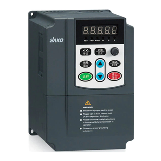
SKI600-7D5G/011P-4 7,5 кВт, 380В SAKO
- Диапазон мощностей: 0.75 кВт~ 22 кВт/380В, 0.75 кВт ~ 2.2 кВт/220В.
- Диапазон входных напряжений: 380В±15% или 220В±15%, 50/б0 Гц.
- Диапазон выходных частот: 0 ~ 500 Гц.
- Тип управления: векторное.
- Автоматическое ограничение тока во время работы, что предотвращает частые отключения по перегрузке.
- Контроль напряжения во время торможения, который предотвращает срабатывание аварии от перенапряжения.
- Перегрузочная способность: 110% номинального тока в течение длительного времени; 150% номинального тока 1 минута; 180% номинального тока 5 секунд.
- Возможность работы с ступенчатыми скоростями через встроенный ПЛК или терминал управления.
- Встроенный ПИД-регулятор: замкнутая система управления параметрами процесса (такими как давление, температура, расход).
- Более 20 функций защиты, таких как перегрузка по току, перенапряжение, пониженное напряжение, перегрев, обрыв фазы и др.
- Встроенный порт RS-485 и поддержка протокола связи Modbus.
- Гарантийный срок 18 месяцев с момента продажи.
Рассчитать доставку
Характеристики
Max потреб. мощность, кВт
—
7,5
Нужна консультация?
Наши специалисты ответят на любой интересующий вопрос
Задать вопрос
Инвертор SAKO VFD SKI780, 220 В, кВт/кВт, 1HP, преобразователь частоты переменного тока для управления скоростью двигателя
Отзывов: 21
21
Рейтинг: 4.90
Последний
отзыв: 28.06.22
Сортировка отзывов
Оценка: 5
Рейтинг отзыва: 4
Дата: 09.11.21
Отзыв:
Продавец отправил заказ на восьмой день из десяти. Вна Украину доставка менее месяца. Инструкцию продавец приложил только на английском языке, хотя по отзывам другие получили на русском. По сути: частотник вполне себе рабочий, испытал на движке 1.1 кВт, на разных частотах, полчаса нагрева нет ни на частотнике ни в движке. Настроек много, для каждого свои, искать по форумам. Товар рекомендую.
Страница отзыва
S***v
Отзывов у пользователя: 35
Оценка: 5
Рейтинг отзыва: 3
Дата: 10.10.20
Отзыв:
Сначала заказал 1.5кв из России, прождал две недели, заказ не отправили, деньги вернули. Затем заказал 2.2кв, доставили за 3 дня. Качественное исполнение, руководство на русском.
Дополненный отзыв:
Изначально настроен на 50Гц. Пришёл шпиндель 2.2Квт 24000об/мин 400Гц, по-умолчанию не запустился, настроил параметры под мотор, все заработало. Вентилятор шумит, но как-то пофиг т.к. шпиндель при раскрутке на полную шумит ещё больше. Размер все-таки не большой по сравнению с другими. Хотел управлять им по modbus, но в руководстве чёт ничего нет, надо искать.
Страница отзыва
W***a
Отзывов у пользователя: 1
Оценка: 5
Рейтинг отзыва: 1
Дата: 11.02.21
Отзыв:
chegou incrivelmente rápido e muito bonito
Страница отзыва
D***v
Отзывов у пользователя: 4
Оценка: 5
Рейтинг отзыва: 1
Дата: 15.01.22
Отзыв:
Заказываю уже второй, первый брал на 1,5 кВт, Продавец отправил заказ в течении нескольких дней. Доставка вна Украину менее месяца. На второй раз продавец отправил инструкцию на русском языке. Есть также информация по форумам относительно настроек. Всё работает, напругу даёт, под нагрузкой пока не проверял. Товар и продавца рекомендую, цена — качество нормальное.


Страница отзыва
G***r
Отзывов у пользователя: 1
Оценка: 5
Дата: 25.01.21
Отзыв:
Товар пришел очень быстро. Качественно упаковано. Прибор испытали в день получения. Работает без нареканий, обороты двигателя плавно регулируются. Единственное замечание неудобные винты соединения проводов.
Страница отзыва
R***s
Отзывов у пользователя: 1
Оценка: 5
Дата: 21.01.21
Отзыв:
Schneller Versand, gut Verpackt und top Qualität!


Страница отзыва
Оценка: 4
Дата: 16.01.21
Отзыв:
Package never arrived, I said gls told me that package sent back to seller. I have provided the seller, gls italian traking to prove it. Seller never replied to my numerous emails, never interested in verifying italy traking. Now i am expecting complaint from aliexpress , but I am very disappointed with both seller and aliexpress service
Дополненный отзыв:
Dopo giorni il pacco, rimandato indietro, è fermo in un magazzino internazionale. Attenzione il traking di gls non funziona, quindi aliexpress non risarcisce. Il negozio non ha mai risposto alle mie domande ne si è interessato al problema. Alla fine l’unico che ha perso i soldi sono io. Sarà anche un buon prodotto, non mi è mai arrivato, ma per me non vale il rischio. Non ripeterò l’errore.


Страница отзыва
M***a
Отзывов у пользователя: 2
Оценка: 5
Дата: 08.11.20
Отзыв:
Buena compra, llega dentro de la fecha señalada de entrega y con seguimiento, me llego integro el Inverter con su manual, falta instalarlo y realizar pruebas
Страница отзыва
R***d
Отзывов у пользователя: 1
Оценка: 4
Дата: 27.03.21
Отзыв:
Отличный частотный за свои деньги, правда мелкие разъёмы(не особо удобно подключать) порадовала инструкция на русском языке

Страница отзыва
B***n
Отзывов у пользователя: 77
Оценка: 5
Дата: 23.03.21
Отзыв:
Good service and quality. Convertet my tool grinder from 3x380v to 3x220v Running Perfect on one phase 220v. Thanks


Страница отзыва
D***r
Отзывов у пользователя: 1
Оценка: 5
Дата: 08.03.21
Отзыв:
Świetny falownik, polecam.
Дополненный отзыв:
Wszystko sprawdzone, podłączone i działa bardzo dobrze, polecam.


Страница отзыва
M***n
Отзывов у пользователя: 2
Оценка: 5
Дата: 23.06.22
Отзыв:
рекомендую к закупке
отличный частотник за такие деньги.
доставка 4 дня, качество сборки отличное!


Страница отзыва
M***n
Отзывов у пользователя: 2
Оценка: 5
Дата: 23.06.22
Отзыв:
рекомендую к закупке
отличный частотник за такие деньги.
доставка 4 дня, качество сборки отличное!
Страница отзыва
o***M
Отзывов у пользователя: 21
Оценка: 5
Дата: 07.01.22
Отзыв:
Отличный частотник. Настоящий заводской Китай. Доставка — молния! Подключил к эл. двигателю-отличный результат! Рекомендую! Жаль, хотел 10звезд поставить, а можно только 5!
Страница отзыва
I***v
Отзывов у пользователя: 5
Оценка: 5
Дата: 30.12.21
Отзыв:
Пристигна за 10 дена от Испания. Работи перфектно на компресор за въздух. Препоръчвам.
Страница отзыва
S***v
Отзывов у пользователя: 34
Оценка: 5
Дата: 30.10.21
Отзыв:
Приехало очень быстро. Хороший частотник, маленький, до 400 Гц, шпиндели запускает.

Страница отзыва