Samsung и Cookies
На этом сайте используются файлы cookie. Нажимая ПРИНЯТЬ или продолжая просмотр сайта, вы разрешаете их использование.
Подробнее
В настоящий момент товары недоступны для заказа на samsung.com/ru
В настоящий момент товары недоступны для заказа на samsung.com/ru
Выберите свое местоположение и язык.

SAMSUNG MEDISON
DIAGNOSTIC ULTRASOUND SYSTEM
HM70A
User Manual
Volume 1
SAMSUNG MEDISON
DIAGNOSTIC ULTRASOUND SYSTEM
Version 1.01
HM70A
User Manual
English
MI68-03033A
PROPRIETRAY INFORMATION AND SOFTWARE LICENSE
The Customer shall keep confidential all proprietary information furnished or disclosed to the Customer
by Samsung Medison, unless such information has become part of the public domain through no fault
of the Customer. The Customer shall not use such proprietary information, without the prior written
consent of Samsung Medison, for any purpose other than the maintenance, repair or operation of the
goods.
Samsung Medison’s systems contain Samsung Medison’s proprietary software in machine-readable
form. Samsung Medison retains all its rights, title and interest in the software except that purchase of
this product includes a license to use the machine-readable software contained in it. The Customer
shall not copy, trace, disassemble or modify the software. Transfer of this product by the Customer
shall constitute a transfer of this license that shall not be otherwise transferable. Upon cancellation or
termination of this contract or return of the goods for reasons other than repair or modification, the
Customer shall return to Samsung Medison all such proprietary information.
Safety Requirements
Classifications:
XX
Type of protection against electrical shock: Class I
XX
Degree of protection against electrical shock (Patient connection): Type BF or CF Applied Part
XX
Degree of protection against harmful ingress of water: Ordinary equipment
XX
Degree of safety of application in the presence of a flammable anesthetic material with air or
with oxygen or nitrous oxide: Equipment not suitable for use in the presence of a flammable
anesthetic mixture with air or with oxygen or nitrous oxide.
XX
Mode of operation: Continuous operation
Electromechanical safety standards met:
XX
Medical Electrical Equipment, Part 1: General Requirements for Basic Safety and Essential
Performance [IEC 60601-1:2005/A1:2012]
XX
Medical Electrical Equipment, Part 1-2: General Requirements for Basic Safety and Essential
Performance- Collateral Standard: Electromagnetic Compatibility - Requirements and Tests [IEC
60601-1-2:2007]
XX
Medical Electrical Equipment, Part 1-6: General Requirements for Basic Safety and Essential
Performance- Collateral Standard: Usability [IEC 60601-1-6:2010]
XX
Medical Electrical Equipment, Part 2-37: Particular Requirements for the Basic Safety and
Essential Performance of Ultrasonic Medical Diagnostic and Monitoring Equipment [IEC 606012-37:2007]
XX
Medical Electrical Equipment, Part 1: General Requirements for Safety [IEC 60601-1:1988 with
A1:1991 and A2:1995]
XX
Medical Electrical Equipment, Part 1-1: General Requirements for Safety - Collateral Standard:
safety Requirement for Medical Electrical Systems [IEC 60601-1-1:2000]
XX
Medical Electrical Equipment, Part 1-2: General Requirements for Safety - Collateral Standard:
Electromagnetic Compatibility - Requirements and Test [IEC 60601-1-2:2001, A1:2004]
XX
Medical Electrical Equipment, Part 1-4 : General Requirements for Safety - Collateral Standard:
Programmable Electrical Medical Systems [IEC 60601-1-4:1996, A1:1999]
XX
Medical Electrical Equipment, Part 2-37: Particular Requirements for Safety - Ultrasonic Medical
Diagnostic and Monitoring Equipment [IEC 60601-2-37: 2001 with A1:2004, A2:2005]
XX
Medical Devices – Application of Risk Management to Medical Devices [ISO 14971:2007]
XX
Medical Electrical Equipment, Part 1: General Requirements for Safety [UL 60601-1:2003]
XX
Medical Electrical Equipment - Part 1: General Requirements for Safety [CAN/CSA C22.2 No.
601.1-M90:1990, with R2003, with R2005]
XX
Biological Evaluation of Medical Devices, Part 1:Evaluation and Testing within a risk management
process [ISO 10993-1 : 2009]
XX
Standard Means for the Reporting of the Acoustic Output of Medical Diagnostic Ultrasonic
Equipment [IEC 61157:2007]
Declarations
CSA mark with the indicators “C” and “US” means that the product is
certified for both the U.S. and Canadian markets, to the applicable U.S. and
Canadian standards.
This is manufacturer’s declaration of product compliance with applicable
EEC directive(s) and the European notified body.
This is manufacturer’s declaration of product compliance with applicable
EEC directive(s).
This is the GMP symbol for Korean Good Manufacturing Practice quality
system regulation.
Precautions For Use
You should be familiar with all of these areas before attempting to use this manual or your ultrasound
system.
Please keep this user guide close to the product as a reference when using the system.
For safe use of this product, you should read ‘Chapter 1. Safety’ and ‘Chapter 4. Maintenance’ in this
manual, prior to starting to use this system.
This manual does not include diagnosis results or opinions. Also, check the measurement
reference for each application’s result measurement before making the final diagnosis.
This product is an ultrasound scanner and cannot be used from a user’s PC. We are not responsible
for errors that occur when the system software is run on a user’s PC.
Only medical doctors or persons supervised by medical doctors should use this system. Persons
who are not qualified must not operate this product.
The manufacturer is not responsible for any damage to this product caused by carelessness and/
or neglect by the user.
Please note that orders are based on the individually agreed specifications and may not contain all
features listed in the User Manual.
It might be possible that some features, options or probes are NOT available in some countries.
All references to standards / regulations and their revisions are valid for the time of publication of
the User Manual.
The figures in the User Manual for illustrational purposes only and may be different from what you
see on the screen or device.
Information contained in this User Manual is subject to change without prior notice.
Products that are not manufactured by Samsung Medison are marked with the trademark of their
respective copyright holders.
The headings below describe vitally important precautions necessary to prevent hazards.
DANGER: Describes precautions necessary to prevent user hazards of great urgency. Ignoring a
DANGER warning will risk life-threatening injury.
WARNING: Used to indicate the presence of a hazard that can cause serious personal injury, or
substantial property damage.
CAUTION: Indicates the presence of a hazard that can cause equipment damage.
NOTE: A piece of information useful for installing, operating and maintaining a system. Not
related to any hazard.
Revision History
The revision history of this User Manual is as follows:
VERSION
DATE
NOTE
v1.01.00-00
2014.11.20
Initial Release
Product Upgrade and Manual Update
Samsung Medison Ultrasound is committed to innovation and continued improvement. Upgrades may
be announced that consist of hardware or software improvements. Updated manuals will accompany
those system upgrades.
Verify that Check if this version of the manual is correct for the system version. If not, please contact the
Customer Service Department.
If You Need Assistance
If you need any assistance with the equipment, like the service manual, please contact the Samsung
Medison Customer Service Department or one of their worldwide customer service representatives,
immediately.
Table of Contents
Table of Contents – Volume 1
Chapter 1 Safety
Purpose of Use............................................................................................................................. 1-3
Contraindications ............................................................................................................................................................... 1-3
Safety Information...................................................................................................................... 1-4
Safety Symbols..................................................................................................................................................................... 1-4
Symbols.................................................................................................................................................................................. 1-5
LABEL....................................................................................................................................................................................... 1-6
Electrical Safety........................................................................................................................... 1-7
Prevention of Electric Shocks......................................................................................................................................... 1-7
ECG-Related Information................................................................................................................................................. 1-8
ESD............................................................................................................................................................................................ 1-9
EMI............................................................................................................................................................................................ 1-9
EMC........................................................................................................................................................................................1-10
Mechanical Safety..................................................................................................................... 1-17
Precautions for Use...........................................................................................................................................................1-17
Moving the Equipment...................................................................................................................................................1-18
Biological Safety....................................................................................................................... 1-19
ALARA Principle.................................................................................................................................................................1-19
Protecting the Environment................................................................................................... 1-34
Correct Disposal of This Product (Waste Electrical & Electronic Equipment).............................................1-34
Battery Pack............................................................................................................................... 1-35
Extended Battery (Optional).................................................................................................. 1-36
Correct Disposal of Batteries in This Product.........................................................................................................1-37
Chapter 2 Introduction
Specification................................................................................................................................ 2-3
Product Configuration .............................................................................................................. 2-6
Monitor................................................................................................................................................................................... 2-7
Control Panel........................................................................................................................................................................ 2-9
Console ................................................................................................................................................................................2-14
15
User Manual
Peripheral Devices............................................................................................................................................................2-16
Video Out.............................................................................................................................................................................2-18
Battery Pack and Extended Battery............................................................................................................................2-21
Probes....................................................................................................................................................................................2-24
HM70A CART(Optional)..................................................................................................................................................2-25
Accessories..........................................................................................................................................................................2-26
Optional Functions...........................................................................................................................................................2-26
Chapter 3 Utilities
Utilities ......................................................................................................................................... 3-3
HELP............................................................................................................................................... 3-5
EZ Exam........................................................................................................................................ 3-6
ECG................................................................................................................................................. 3-7
ADVR (Optional).......................................................................................................................... 3-9
Biopsy.......................................................................................................................................... 3-11
Setup........................................................................................................................................... 3-13
General..................................................................................................................................................................................3-13
Display...................................................................................................................................................................................3-18
Annotate...............................................................................................................................................................................3-21
Peripherals...........................................................................................................................................................................3-25
User Defined Key...............................................................................................................................................................3-27
Miscellaneous.....................................................................................................................................................................3-29
Option...................................................................................................................................................................................3-32
DICOM...................................................................................................................................................................................3-34
AutoCalc...............................................................................................................................................................................3-46
Power.....................................................................................................................................................................................3-47
About.....................................................................................................................................................................................3-49
Histogram................................................................................................................................... 3-50
Post Curve.................................................................................................................................. 3-52
Monitor Calibration..........................................................................................................................................................3-52
Gamma..................................................................................................................................................................................3-54
2D Post..................................................................................................................................................................................3-54
Color Map.............................................................................................................................................................................3-55
D Post.....................................................................................................................................................................................3-55
M Post....................................................................................................................................................................................3-55
16
Table of Contents
Measurement Settings ........................................................................................................... 3-56
General..................................................................................................................................................................................3-57
OB............................................................................................................................................................................................3-70
Cardiac...................................................................................................................................................................................3-78
Vascular.................................................................................................................................................................................3-80
Urology.................................................................................................................................................................................3-82
Fetal Heart............................................................................................................................................................................3-84
EZ Exam Setup........................................................................................................................... 3-86
Storage Manager...................................................................................................................... 3-90
Userset Manager....................................................................................................................... 3-92
Menu Edit................................................................................................................................... 3-94
Chapter 4 Maintenance
Operational Environment......................................................................................................... 4-3
Product Maintenance................................................................................................................ 4-4
Cleaning and disinfecting................................................................................................................................................ 4-4
Accuracy Checks.................................................................................................................................................................. 4-5
Battery Pack Management....................................................................................................... 4-6
Replacing the Battery Pack.............................................................................................................................................. 4-6
Recharging the Battery Pack........................................................................................................................................... 4-7
Storing the Battery Pack................................................................................................................................................... 4-8
Disposing of the Battery Pack........................................................................................................................................ 4-8
Extended Battery Management.............................................................................................. 4-9
Replacing the Extended Battery................................................................................................................................... 4-9
Charging the Extended Battery...................................................................................................................................4-10
Storing the Extended Battery.......................................................................................................................................4-11
Disposing of the Extended Battery............................................................................................................................4-11
Information Maintenance....................................................................................................... 4-12
Backing Up User Setting.................................................................................................................................................4-12
Backing Up Patient Information..................................................................................................................................4-12
Software...............................................................................................................................................................................4-12
17
User Manual
Chapter 5 Probes
Probes........................................................................................................................................... 5-3
Ultrasound transmission Gel........................................................................................................................................5-13
Using Sheaths.....................................................................................................................................................................5-14
Probe Safety Precautions...............................................................................................................................................5-15
Cleaning and Disinfecting the Probe........................................................................................................................5-17
Biopsy.......................................................................................................................................... 5-26
Biopsy Kit Components..................................................................................................................................................5-26
Using the Biopsy Kit.........................................................................................................................................................5-27
Assembling the Biopsy Kit.............................................................................................................................................5-30
Cleaning and Disinfecting the Biopsy Kit................................................................................................................5-34
**Reference Manual
A Reference Manual (English) is supplied with this product.
18
Chapter
1
Safety
Purpose of Use...................................................1-3
Contraindications ....................................................................1-3
Safety Information...........................................1-4
Safety Symbols..........................................................................1-4
Symbols........................................................................................1-5
LABEL............................................................................................1-6
Electrical Safety.................................................1-7
Prevention of Electric Shocks...............................................1-7
ECG-Related Information.......................................................1-8
ESD.................................................................................................1-9
EMI..................................................................................................1-9
EMC..............................................................................................1-10
Mechanical Safety......................................... 1-17
Precautions for Use................................................................1-17
Moving the Equipment........................................................1-18
Biological Safety............................................ 1-19
ALARA Principle......................................................................1-19
Protecting the Environment......................... 1-34
Correct Disposal of This Product
(Waste Electrical & Electronic Equipment)...................1-34
Chapter
1
Battery Pack................................................... 1-35
Extended Battery (Optional)........................ 1-36
Correct Disposal of Batteries in This Product...............1-37
Chapter 1 Safety
Purpose of Use
Diagnostic Ultrasound System and transducers are intended for diagnostic ultrasound imaging and
fluid analysis of the human body.
The clinical applications include: Fetal, Abdominal, Pediatric, Small Organs, Neonatal Cephalic, Adult
Cephalic, Trans-rectal, Trans-vaginal, Muscular-Skeletal (conventional, superficial), Cardiac Adult, Cardiac
Pediatric and Peripheral-vessel.
NOTE: For detailed information on applications and presets, please refer to ‘Chapter 2. Introduction’
and ‘Chapter 5. Probes’ in this user manual.
Contraindications
This product must not be used for ophthalmological applications, or any other use that involves the
ultrasound beam passing through the eyeball.
CAUTION:
XX
Federal law restricts this device to sale by or on the order of a physician.
XX
The method of application or use of the device is described in the manual ‘Chapter 6. Starting
Diagnosis’ and ‘Chapter 7. Diagnosis Modes’.
1-3
User Manual
Safety Information
Please read the following safety information before using this product. It is relevant to the ultrasound
system, the probes, the recording devices, and any of the optional equipment.
This product is intended for use by, or by the order of, and under the supervision of, a licensed physician
who is qualified for direct use of medical devices.
Safety Symbols
The International Electrotechnical Commission (IEC) has established a set of symbols for medical
electronic equipment, which classify a connection or warn of potential hazards. The classifications and
symbols are shown below.
Symbols
1-4
Description
Symbols
Description
WARNING: The accompanying
information must be followed to prevent
serious accidents and/or damage to
property.
Data Input/Output port
CAUTION: The accompanying
information helps to prevent minor
accidents and/or damage to property.
Input port
Refer to the User Manual.
Output port
Follow the User Manual.
Print remote output
CAUTION: Risk of electric shock
Foot Switch Port
Type BF applied part (Classification
based on degree of protection against
electric hazard)
ECG port
Defibrillation-proof type CF applied
part (Classification based on degree of
protection against electric hazard)
USB port
Power on/off
Network port
Chapter 1 Safety
Symbols
Description
Symbols
Description
Power on
Microphone Port
Power off
Probe port
Power ON for part of the product
Protected against vertically falling water
drops
Power Off for part of the product
Protected against the effects of
temporary immersion in water
Alternating current voltage source
Protected against the effects of
continuous immersion in water
Direct current voltage source
CAUTION: Electrostatic sensitive devices
(ESD)
Dangerous voltage (Indicates dangerous
voltages over 1000V AC or 1500V DC)
Do not sit on the product.
Protective earth (ground)
Do not push the product.
Equipotentiality
Do not lean against the product.
Data output port
Be mindful of the space. Do not place a
finger, and or any part of your body in
the space.
Data input port
Symbols
Symbols
Description
Authorized Representative In The
European Community
Symbols
Description
Manufacturer
1-5
User Manual
LABEL
Phrases containing the words ‘warning’ and/or ‘caution’ are displayed on the product’s surface in order
to protect it.
1-6
Chapter 1 Safety
Electrical Safety
This equipment is categorized as a Class I device with Type BF or Type CF (ECG) applied parts.
Prevention of Electric Shocks
WARNING:
XX
Electric shocks may result if this system, including all of its externally mounted recording and
monitoring devices, is not properly grounded.
XX
Never open the cover of the product. This product uses levels of voltage that are potentially
dangerous. All internal component repairs and part replacements must be performed by
Samsung Medison’s service department.
XX
Always check the product’s casing, cables, cords, and plugs for damage before using the
product. Disconnect the power source and do not use the equipment if the housing is damaged
(for example cracked or chipped), or if the cable is worn.
XX
Always disconnect the system from the wall outlet prior to cleaning the system.
XX
All patient contact devices, such as the probe, must be detached from the patient prior to using
a high-voltage defibrillator.
XX
Never use the product in the presence of flammable or anesthetic gas. There is a risk of
explosion.
XX
Avoid installing the system in such a way that it is difficult for the operator to disconnect it from
the power source.
XX
The AC Adapter and the Extended Battery are specified as part of this product. When using
an AC Adapter and Extended Battery, only use an AC Adapter and an Extended Battery that
are recommended by Samsung Medison. (AC Adapter: BridgePower Corp., BPM200S19F02;
Extended Battery: Elentec Co., Ltd., EE1630SMA)
XX
Do not use together with HF surgical equipment. HF surgical equipment may be damaged,
which may result in fire.
XX
The System must only be connected to a supply mains with protective earth to avoid risk of
electric shock.
1-7
User Manual
CAUTION:
XX
The system has been designed for 100-240VAC; you should select the input voltage of any
connected printer and VCR. Prior to connecting a peripheral power cord, verify that the voltage
indicated on the power cord matches the voltage rating of the peripheral device.
XX
An isolation transformer protects the system from power surges. The isolation transformer
continues to operate when the system is in standby.
XX
Do not immerse the cable in liquids. The power cord is not waterproof.
XX
Do not allow the interior of the system to be exposed to, or immersed in, liquid. In such cases,
fire, electric shock, injury, or damage to the product may occur.
XX
The auxiliary socket outlets installed on this system are rated 100-120VAC and 200-240VAC with
a maximum total load of 450VA. Use these outlets only for supplying power to equipment that is
intended to be part of the ultrasound system. Do not connect additional multiple-socket outlets
or extension cords to the system.
XX
Connecting a device that is not listed in this manual to the auxiliary socket outlet may cause an
electrical hazard.
XX
Do not touch the SIP/SOP terminal on the product while diagnosing the patient. There is a risk
of electric shock from leakage current.
Additional equipment connected to medical electrical equipment must comply with the respective
IEC standards (e.g. IEC 60950/EN 60950 for data processing equipment, IEC 60601-1/EN 60601-1 for
medical devices). Furthermore, all components of the product shall comply with the requirements for
medical electrical systems (IEC 60601-1-1/EN 60601-1-1). All persons connecting accessory equipment
to the signal input or output ports of medical electrical equipment should make sure that the accessory
complies with IEC 60601-1-1/EN 60601-1-1.
ECG-Related Information
WARNING:
XX
This product does not provide an ECG monitoring function. Therefore, it does not recognize
unsuitable ECG signals.
XX
Do not use ECG electrodes for HF surgical equipment. HF surgical equipment may be damaged,
which may result in fire.
XX
Do not use ECG electrodes during cardiac pacemaker procedures or any procedures that involve
other types of electrical stimulators.
XX
Do not use ECG leads and electrodes in an operating room.
1-8
Chapter 1 Safety
ESD
Electrostatic discharge (ESD), which is commonly referred to as static shock, is a naturally occurring
phenomenon. ESD is most prevalent during conditions of low humidity, including during heater or airconditioner use. The static shock or ESD is a discharge of the electrical energy build-up from a charged
individual to a lesser or non-charged individual or object. An ESD occurs when an individual with an
electrical energy build-up comes in contact with conductive objects such as metal doorknobs, file
cabinets, computer equipment, and even other individuals.
CAUTION:
XX
The level of electrical energy discharged from a system user or patient to an ultrasound system
can be significant enough to cause damage to the system or probes.
XX
Always perform the ESD preventive procedure before using connectors bearing the ESD
warning symbol.
−− Apply anti-static spray to carpets or linoleum.
−− Use anti-static mats.
−− Ground the product to the patient’s table or bed.
XX
It is highly recommended that the user be given training on ESD-related warning symbols and
preventive procedures.
EMI
Although this system has been manufactured in compliance with existing EMI (ElectroMagnetic
Interface) requirements, use of this system in the presence of an electromagnetic field can cause
degradation of the ultrasound image or product damage.
If this occurs often, Samsung Medison suggests a review of the environment in which the system is
being used, to identify possible sources of electromagnetic emissions. These emissions could be from
other electrical devices used within the same room or an adjacent room. Communication devices such
as cellular phones and pagers can cause these emissions. The existence of radios, TVs, or microwave
transmission equipment nearby can also cause interference.
CAUTION: In cases where EMI is causing disturbances, it may be necessary to relocate this system.
1-9
User Manual
EMC
The testing for EMC(Electromagnetic Compatibility) of this system has been performed according to the
international standard for EMC with medical devices (IEC 60601-1-2). In Europe, the IEC standard was
adopted as the European norm (EN 60601-1-2).
Guidance and Manufacturer’s Declaration - Electromagnetic Emission
This product is intended for use in the electromagnetic environment specified below. The user is to
ensure that the product is used in the following environment.
Emission test
Compliance
Electromagnetic environment - guidance
RF Emission
CISPR 11
Group 1
The Ultrasound System uses RF energy only for its internal
function. Therefore, its RF emissions are very low and are not
likely to cause any interference in nearby electronic equipment.
RF Emission
CISPR 11
Class A
Harmonic Emission
IEC 61000-3-2
Class A
Flicker Emission
IEC 61000-3-3
1-10
Complies
The Ultrasound System is suitable for use in all establishments
other than domestic, and may be used in domestic
establishments and those directly connected to the public lowvoltage power supply network that supplies buildings used for
domestic purposes, provided the following warning is heeded:
Warning: This system is intended for use by healthcare
professionals only. This system may cause radio interference
or may disrupt the operation of nearby equipment. It may be
necessary to take mitigation measures, such as re-orienting or
relocating the Ultrasound System or shielding the location.
Chapter 1 Safety
Approved Cables, Probes and Peripherals for EMC
Cables
Cables connected to this product may affect its emissions; use only the cable types and lengths
listed in the table below.
Cable
Type
Length
DVI
Shielded
Normal
USB
Shielded
Normal
LAN(RJ45)
Twisted pair
Any
MIC
Unshielded
Any
Printer Remote
Unshielded
Any
Audio R.L
Shielded
Normal
Foot Switch
Shielded
2.99m
Probes
The image probe used with this product may affect its emission. The probe listed in ‘Chapter
5. Probes’ when used with this product, have been tested to comply with the group1 Class A
emission as required by International Standard CISPR 11.
Peripherals
Peripherals used with this product may affect its emissions.
CAUTION: When connecting other customer-supplied accessories to the system, it is the user’s
responsibility to ensure the electromagnetic compatibility of the system.
WARNING: The use of cables, probes, and peripherals other than those specified may result in
increased emission or decreased Immunity of the Ultrasound System.
1-11
User Manual
Immunity test
Electrostatic
discharge (ESD)
IEC 60601 Test level
Compliance level
±6KV Contact
±6KV Contact
±8KV air
±8KV air
IEC 61000-4-4
±2KV
for power supply lines
±1KV
for input/output lines
±2KV
for power supply lines
±1KV
for input/output lines
Surge
±1KV differential mode
±1KV differential mode
IEC 61000-4-5
±2KV common mode
±2KV common mode
<5% Uт for 0.5 cycles
(>95% dip in Uт)
<5% Uт for 0.5 cycles
(>95% dip in Uт)
40% Uт for 5 cycles
(60% dip in Uт)
40% Uт for 5 cycles
(60% dip in Uт)
70% Uт for 25 cycles
(30% dip in Uт)
70% Uт for 25 cycles
(30% dip in Uт)
<5% Uт for 5 s
(<95% dip in Uт)
<5% Uт for 5 s
(<95% dip in Uт)
3 A/m
3 A/m
IEC 61000-4-2
Electrical fast
transient/burst
Voltage dips, short
interruptions and
voltage variations
on power supply
input lines
IEC 61000-4-11
Power frequency
(50/60Hz) magnetic
field
IEC 61000-4-8
NOTE: Uт is the A.C. mains voltage prior to application of the test level.
1-12
Electromagnetic
environment - guidance
Floors should be wood,
concrete or ceramic tile.
If floors are covered with
synthetic material, the
relative humidity should be
at least 30%.
Mains power quality
should be that of a typical
commercial or hospital
environment.
Mains power quality
should be that of a typical
commercial or hospital
environment.
Mains power quality
should be that of a typical
commercial or hospital
environment. If the user
of this product requires
continued operation during
power mains interruptions,
it is recommended that this
product be powered from
an uninterruptible power
supply or a battery.
Power frequency magnetic
fields should be at levels
characteristic of a typical
location in a typical
commercial or hospital
environment.
Chapter 1 Safety
Immunity test
Conducted RF
IEC 61000-4-6
IEC 60601
test level
3 Vrms
150 kHz
to 80 MHz
Compliance
level
3V
Electromagnetic environment - guidance
Portable and mobile RF communications
equipment should be used no closer to any part of
the Ultrasound System, including cables, than the
recommended separation distance calculated from
the equation applicable to the frequency of the
transmitter.
Recommended separation distance
1.2
Radiated RF
IEC 61000-4-3
3 V/m
80 MHz
to 2.5 GHz
3 V/m
1.2
80MHz to 800MHz
2.3
800MHz to 2.5GHz
Where P is the maximum output power rating
of the transmitter in watts (W) according to
the transmitter manufacturer and d is the
recommended separation distance in meters (m).
Field strengths from fixed RF transmitters, as
determined by an electromagnetic site survey, a
should be less than the compliance level in each
frequency range. b
Interference may occur in the vicinity of
equipment marked with the following symbol :
NOTE 1: At 80MHz and 800MHz, the higher frequency range applies.
NOTE 2: These guidelines may not apply in all situations. Electromagnetic propagation is affected by
absorption and reflection from structures, objects and people.
F ield strengths from fixed transmitters, such as base stations for radio (cellular/cordless) telephones
and land mobile radios, amateur radio, AM and FM radio broadcast and TV broadcast cannot be
predicted theoretically with accuracy. To assess the electromagnetic environment due to fixed RF
transmitters, an electromagnetic site survey should be considered. If the measured field strength
in the location in which the Ultrasound System is used exceeds the applicable RF compliance
level above, the Ultrasound System should be observed to verify normal operation. If abnormal
performance is observed, additional measures may be necessary, such as re-orienting or relocating
the Ultrasound System, or using a shielded location with a higher RF shielding effectiveness and
filter attenuation.
b
Over the frequency range 150kHz to 80MHz, field strengths should be less than 3 V/m.
a
1-13
User Manual
Recommended distance between wireless communication device and
this product
This product is intended for use in an electromagnetic environment in which radiated RF
disturbances are controlled. The customer or the user of this product can help prevent
electromagnetic interference by maintaining a minimum distance between portable and mobile RF
communications equipment (transmitters) and this product as recommended below, according to
the maximum output power of the communications equipment.
Separation distance according to frequency of transmitter [m]
Rated maximum output
power of transmitter
[W]
150kHz to 80MHz
80MHz to 800MHz
800MHz to 2.5GHz
1.2
1.2
2.3
0.01
0.12
0.12
0.23
0.1
0.38
0.38
0.73
1
1.2
1.2
2.3
10
3.8
3.8
7.3
100
12
12
23
For transmitters rated at a maximum output power not listed above, the recommended separation distance
d in meters (m) can be estimated using the equation applicable to the frequency of the transmitter,
where p is the maximum output power rating of the transmitter in watts (W) according to the transmitter
manufacturer.
NOTE 1: At 80MHz and 800MHz, the separation distance for the higher frequency range applies.
NOTE 2: These guidelines may not apply in all situations. Electromagnetic propagation is affected by
absorption and reflection from structures, objects and people.
Electromagnetic environment – Guidance
It is recommended to use ultrasound systems in shielded locations offering RF shielding
effectiveness, with shielded cables. Field strengths outside the location shielded from fixed RF
transmitters, as determined by an electromagnetic site survey, should be less than 3V/m.
It is essential to verify that the actual shielding effectiveness and filter attenuation of the shielded
location meet the minimum specifications.
CAUTION: If the system is connected to other customer-supplied equipment, such as a local area
network (LAN), Samsung Medison cannot guarantee that the remote equipment will work correctly
in the presence of electromagnetic emission phenomena.
1-14
Chapter 1 Safety
Avoiding Electromagnetic Interference
Typical interference on Ultrasound Imaging Systems varies depending on Electromagnetic
phenomena. Please refer to the following table:
Imaging Mode
ESD1
For sector imaging probes,
white radial bands or flashes
in the centerlines of the
image.
2D
M
Change of operating
mode, system settings,
or system reset.
Brief flashes in the
displayed or recorded
image.
Color
Doppler
RF2
For linear imaging probes,
white vertical bands,
sometimes more pronounced
on the sides of the image.
Power Line3
White dots, dashes, diagonal
lines, or diagonal lines near
the center of the image.
Increase in the image
background noise or white M
mode lines.
White dots, dashes, diagonal
lines, or increase in image
background noise.
Color flashes, radial or
vertical bands, increase in
background noise, or changes
in color image.
Color flashes, dots, dashes,
or changes in the color noise
level.
Horizontal lines in the
spectral display or tones,
abnormal noise in the audio,
or both.
Vertical lines in the spectral
display, popping type noise in
the audio, or both.
1. ESD caused by discharging of electric charge build-up on insulated surfaces or persons.
2. RF energy from RF transmitting equipment such as portable phones, hand-held radios, wireless devices,
commercial radio and TV, and so on.
3. Conducted interference on powerlines or connected cables caused by other equipment, such as
switching power supplies, electrical controls, and natural phenomena such as lightning.
A medical device can either generate or receive electromagnetic interference. The EMC standards
describe tests for both emitted and received interference.
Samsung Medison’s ultrasound systems do not generate electromagnetic interference in excess of
the referenced standards.
An Ultrasound System is designed to receive signals at radio frequency and is therefore susceptible
to interference generated by RF energy sources. Examples of other sources of interference are
medical devices, information technology products, and radio and television transmission towers.
Tracing the source of radiated interference can be a difficult task. Customers should consider the
following in an attempt to locate the source:
1-15
User Manual
XX
Is the interference intermittent or constant?
XX
Does the interference show up only with one transducer operating at the same frequency or
with several transducers?
XX
Do two different transducers operating at the same frequency have the same problem?
XX
Is the interference present if the system is moved to a different location in the facility?
The answers to these questions will help determine if the problem resides with the system or the
scanning environment. Please answer each question, and then contact the Samsung Medison
service department.
1-16
Chapter 1 Safety
Mechanical Safety
Precautions for Use
CAUTION:
XX
Do not apply excessive force to the product.
XX
Install and use the product at a stable location. Use of the Samsung Medison cart (sold
separately) is recommended.
XX
Do not use the product with it placed on your lap. You might get burned.
XX
Never attempt to modify the product in any way.
XX
Read the instructions on safe operation of the product if using the product after a prolonged
period of non-use.
XX
Make sure that other objects, such as pieces of metal, do not enter the system.
XX
Do not block the ventilation slots.
XX
Do not store the product inside a bag or any other enclosed space while it is powered on.
XX
Do not pull on the power cord to unplug the product. Doing so might damage the cord and
cause the product to short-circuit, or the cord itself to break. Unplug the cord by pulling on the
plug itself.
XX
Excessive bending or twisting of cables, or parts that are applied to the patient, may cause
failure or intermittent operation of the system.
XX
Improper cleaning or sterilization of parts that are applied to the patient may cause permanent
damage.
XX
Servicing the product, including repairs and the replacement of parts, must be done by qualified
Samsung Medison service personnel. Assuming that the product is used in accordance with
the guidelines contained in this manual and maintained by qualified service personnel, the
expected lifespan of the product is approximately 7 years.
Please refer to ‘Chapter 4. Maintenance’ for detailed information on protection, cleaning, and
disinfecting the equipment.
1-17
User Manual
Moving the Equipment
Firmly grip the handle on the front of the product and move the product slowly. Alternatively, you can
use the Samsung Medison cart (sold separately).
CAUTION: Power off the product and disconnect all cables before moving it.
NOTE: If using the recommended cart, avoid leaving the cart unattended on an uneven surface.
If you must leave the cart on an uneven surface, engage the brakes attached to the casters.
1-18
Chapter 1 Safety
Biological Safety
WARNING:
XX
Ultrasound waves may have damaging effects on cells and, therefore, may be harmful to the
patient. If there is no medical benefit, minimize the exposure time and maintain the ultrasound
wave output level at low. Please refer to the ALARA principle.
XX
Do not use the system if an error message appears on the video display indicating that a
hazardous condition exists. Note the error code, turn off the power to the system, and call the
Samsung Medison service department in your area.
XX
Do not use a system that exhibits erratic or inconsistent updating. Discontinuities in the
scanning sequence are an indication of a hardware failure that should be corrected before use.
XX
The system limits the maximum contact temperature to 43 degree Celsius, and the ultrasonic
waves output observes American FDA regulations.
ALARA Principle
Performing diagnoses using an ultrasound device is defined by the “As Low As Reasonably Achievable”
(ALARA) principle. The decision as to what is reasonable should be left to the judgment and insight of
qualified personnel. No set of rules can be formulated that would be sufficiently complete to dictate
the correct response for every circumstance. By keeping ultrasound exposure as low as possible while
obtaining diagnostic images, users can minimize ultrasonic bioeffects.
Since the threshold for diagnostic ultrasound bioeffects is undetermined, it is the sonographer’s
responsibility to control the total energy transmitted into the patient. The sonographer must reconcile
exposure time with diagnostic image quality. To ensure diagnostic image quality and limit exposure
time, the ultrasound system provides controls that can be manipulated during the exam to optimize
the results of the exam.
The ability of the user to abide by the ALARA principle is important. Advances in diagnostic ultrasound,
not only in the technology but also in the applications of the technology, have resulted in the need
for more and better information to guide the user. This important information is based on a variety of
ultrasound output data, and plays an important role in putting the ALARA principle into effect.
There are numerous variables that affect the way in which the output display indices can be used to
implement the ALARA principle. These variables include mass, body size, location of the bone relative
to the focal point, attenuation in the body, and ultrasound exposure time. Among these, exposure time
is the variable that one must pay the most attention to. For, unlike other variables, exposure time is
entirely controlled by the operator of the ultrasound system.
1-19
User Manual
Applying ALARA
The system-imaging mode used depends upon the information needed. 2D-mode and M-mode
imaging provide anatomical information, while Doppler, Power, and Color imaging provide
information about blood flow. Scanned modes like 2D-mode, Power, or Color, disperse or scatter
the ultrasonic energy over an area, while unscanned modes like M-mode or Doppler concentrate
ultrasonic energy. Understanding the nature of the imaging mode being used allows the
sonographer to apply the ALARA principle with informed judgment. The probe frequency, system
set-up values, scanning techniques, and operator experience aid the sonographer in meeting
the definition of the ALARA principle. The decision as to the amount of acoustic output is, in the
final analysis, up to the system operator. This decision must be based on the following factors:
type of patient, type of exam, patient history, ease or difficulty of obtaining diagnostically useful
information, and the potential localized heating of the patient due to probe surface temperatures.
Prudent use of the system occurs when patient exposure is limited to the lowest index reading for
the shortest amount of time necessary to achieve acceptable diagnostic results.
Although a high index reading does not mean that a bioeffect is actually occurring, a high index
reading should be taken seriously. Every effort should be made to reduce the possible effects of a
high index reading. Limiting exposure time is an effective way to accomplish this goal.
There are several system controls that the operator can use to adjust the image quality and limit
the acoustic intensity. These controls are related to the techniques that an operator might use to
implement ALARA. These controls can be divided into three categories: direct, indirect, and receiver
controls.
Direct Controls
Application selection and the output intensity control directly affect acoustic intensity. There are
different ranges of allowable intensity or output based on your selection. Selecting the correct
range of acoustic intensity for the application is one of the priorities required during any exam. For
example, peripheral vascular intensity levels are not recommended for fetal exams. Some systems
automatically select the proper range for a particular procedure, while others require manual
selection. Ultimately, the user bears the responsibility for proper clinical use. This Samsung Medison
system provides both automatic and user-definable settings.
Output has a direct impact on acoustic intensity. Once the application has been established, the
output control can be used to increase or decrease the intensity output. The output control allows
you to select intensity levels less than the defined maximum. Prudent use dictates that you select the
lowest output intensity consistent with good image quality.
1-20
Chapter 1 Safety
Indirect Controls
The indirect controls are those that have an indirect effect on the acoustic intensity. These controls
affect the imaging mode, pulse repetition frequency, focus depth, pulse length, and probe selection.
The choice of imaging mode determines the nature of the ultrasound beam. 2D-mode is a scanned
mode; Doppler is a stationary or unscanned mode. A stationary ultrasound beam concentrates
energy on a single location. A moving or scanned ultrasound beam disperses the energy over a
wide area and the beam is only concentrated on a given area for a fraction of the time necessary in
unscanned mode.
The pulse repetition frequency or rate refers to the number of ultrasound bursts of energy over a
specific period of time. The higher the pulse repetition frequency, the more pulses of energy in a
given period of time. Several controls affect pulse repetition frequency: Focal depth, display depth,
sample volume depth, color sensitivity, number of focal zones, and sector width controls.
The focus of the ultrasound beam affects the image resolution. Maintaining or increasing the
resolution at a different focal zone involves the adjustment of numerous outputs from the focal
zone. This output adjustment is one of the system’s optimization features. Different exams require
different focal depths. Setting the focus to the proper depth improves the resolution of the structure
of interest.
Pulse length is the time during which the ultrasonic burst is turned on. The longer the pulse, the
greater the time-average intensity value. The greater the time-average intensity, the greater the
likelihood of temperature increase and cavitations. Pulse length, burst length, and pulse duration
refer to the output pulse duration in pulsed Doppler mode. Increasing the Doppler sample volume
increases the pulse length.
Probe selection affects intensity indirectly. Tissue attenuation changes with frequency. The higher
the probe operating frequency, the greater the attenuation of the ultrasonic energy. Higher probe
operating frequencies require greater output intensity to scan at a deeper depth. To scan deeper at
the same output intensity, a lower probe frequency is required. Using more gain and output beyond
a point, without corresponding increases in image quality, can mean that a lower frequency probe is
needed.
Receiver Controls
Receiver controls are used by the operator to improve image quality. These controls have no effect
on output. Receiver controls only affect how the ultrasound echo is received. These controls include
gain, TGC, dynamic range, and image processing. The important thing to remember, relative to
output, is that receiver controls should be optimized before increasing output. For example; before
increasing output, optimize gain to improve image quality.
1-21
User Manual
Additional Considerations
Ensure that scanning time is kept to a minimum, and ensure that only medically required scanning
is performed. Never compromise quality by rushing an exam. A poor exam will require a followup, which ultimately increases the scanning time. Diagnostic ultrasound is an important tool in
medicine, and, like any tool, should be used efficiently and effectively.
Output Display Features
The system output display comprises two basic indices: a mechanical index and a thermal index. The
thermal index consists of the following indices: soft tissue (TIs), bone (TIb) and cranial bone (TIc). One
of these three thermal indices will be displayed at all times. Which one is determined by the system
preset or user choice, depending upon the application at hand.
The mechanical index is continuously displayed over the range of 0.0 to 1.9, in increments of 0.1.
The thermal index consists of the three indices, and only one of these is displayed all the time. Each
probe application has an appropriate default selection. The TIb or TIs is continuously displayed over
the range of 0.0 to maximum output, based on the probe and application, in increments of 0.1.
The default setting of the application-specific nature is also an important factor of index selection.
A default setting is a system control state which is preset by the manufacturer or the operator.
The system has default index settings for the probe application. The default settings are applied
automatically by the ultrasound system when the power is turned on, new patient data is entered
into the system database, or a change of application takes place.
The decision as to which of the three thermal indices to display should be based on the following
criteria:
Appropriate index for the application: TIs is used for imaging soft tissue, and TIb for a focus at or near
a bone. Elements such as fluid, bone, and blood flow may act as artifacts that increase or decrease
the TI. A highly attenuating tissue path, for example, may cause the potential for local zone heating
to be lower than the thermal index displays.
The selection of scanned modes or unscanned modes of operation also affect the thermal index.
For scanned modes, heating tends to be near the surface; for unscanned modes, the potential for
heating tends to be deeper in the focal zone.
Always limit ultrasound exposure time. Do not rush the exam. Ensure that the indices are kept to a
minimum, and that exposure time is limited without compromising diagnostic sensitivity.
1-22
Chapter 1 Safety
Mechanical Index (MI) Display
Mechanical bioeffects are threshold phenomena that occur when a certain level of output
is exceeded. The threshold level varies, however, with the type of tissue. The potential for
mechanical bioeffects varies with peak pressure and ultrasound frequency. The MI accounts for
these two factors. The higher the MI value, the greater the likelihood of mechanical bioeffects
occurring. However, there is no specific MI value that means that a mechanical effect will actually
occur. The MI should be used as a guide for implementing the ALARA principle.
Thermal Index (TI) Display
The TI informs the user of the potential for temperature increase occurring at the body surface,
within body tissue, or at the point of focus of the ultrasound beam on bone. The TI is an estimate
of the temperature increase in specific body tissues. The actual amount of any temperature rise
is influenced by factors such as tissue type, vascularity, and mode of operation. The TI should be
used as a guide for implementing the ALARA principle.
The bone thermal index (TIb) informs the user about potential heating at or near the focus after
the ultrasound beam has passed through soft tissue or fluid, such as the skeletal structure of a 2-3
month old fetus. The cranial bone thermal index (TIc) informs the user about the potential heating
of bone at or near the surface, for example, the cranial bone. The soft tissue thermal index (TIs)
informs the user about the potential for heating within soft homogeneous tissue. TIc is displayed
when you select a trans-cranial application.
You can select whether to display the TI at Setup > Display > Display > Option > TI Display.
Mechanical and Thermal indices Display Precision and Accuracy
The Mechanical and Thermal Indices on the system are precise to 0.1 units.
The MI and TI display accuracy estimates for the system are given in the Acoustic Output Tables
section of this manual. These accuracy estimates are based on the variability ranges of probes and
systems, inherent acoustic output modeling errors, and the measurement variability, as described
below.
The displayed values should be interpreted as relative information to help the system operator
achieve the ALARA principle through prudent use of the system. The values should not be
interpreted as actual physical values of investigated tissue or organs. The initial data that is
used to support the output display is derived from laboratory measurements based on the
AIUM measurement standard. The measurements are then put into algorithms to calculate the
displayed output values.
1-23
User Manual
Many of the assumptions used in the process of measurement and calculation are conservative
in nature. Over-estimation of actual in situ exposure, for the vast majority of tissue paths, is built
into the measurement and calculation process. For example, the acoustic output values measured
underwater are de-rated using a conservative, industry standard, attenuation coefficient of 0.3dB/
cm-MHz.
Conservative values for tissue characteristics were selected for use in the TI models. Conservative
values for tissue or bone absorption rates, blood perfusion rates, blood heat capacity, and tissue
thermal conductivity were selected.
A steady state temperature rise is assumed in the industry standard TI models, and the
assumption is made that the ultrasound probe is held steady in one position long enough for a
steady state to be reached.
A number of factors are considered when estimating the accuracy of display values: Hardware
variations, algorithm accuracy estimation, measurement variability and variability among probes
and systems are significant factors. Probe deviation results from piezoelectric crystal efficiencies,
process-related impedance differences, and sensitive lens focusing parameter variations.
Differences in the system pulse voltage control and efficiencies are also a contributor to variability.
There are inherent uncertainties in the algorithms used for estimating acoustic output values over
the range of possible system operating conditions and pulse voltages. Inaccuracies in laboratory
measurements are related to differences in hydrophone calibration and performance, positioning,
alignment and digitization tolerances, and variability among test operators.
The conservative assumptions of the output estimation algorithms of linear propagation,
at all depths, through a 0.3dB/cm-MHz attenuated medium are not taken into account in
the calculation of the accuracy estimate displayed. Neither linear propagation nor uniform
attenuation at the 0.3dB/cm-MHz rate occurs in underwater measurements, or in most
tissue paths in the body. In the body, different tissues and organs have dissimilar attenuation
characteristics. In water, there is almost no attenuation. (In the body, and particularly in
underwater measurements, non-linear propagation and saturation losses occur as pulse voltages
increase.
The display accuracy estimates take into account the variability ranges of probes and systems,
inherent acoustic output modeling errors, and the measurement variability. Display accuracy
estimates are measured according to AIUM measurement standards but not based on errors
caused during the measurement or inherent errors. They are also independent of the effects of
non-linear loss on the measured values.
1-24
Chapter 1 Safety
Control Effect – Controls Affecting the Indices
As various system controls are adjusted, the TI and MI values may change. This will be most apparent
as the Power control is adjusted; however, other system controls will also affect the on-screen output
values.
Power
The power controls the system’s acoustic output. Two real-time output values are on the screen: a
TI and a MI. They change as the system responds to Power adjustments.
In combined modes, such as simultaneous Color, 2D-mode, and pulsed Doppler, the individual
modes each add to the total TI. Each mode is a vital contributor to this total; the displayed MI will
be from the mode with the largest peak pressure.
2D Mode Controls
2D-mode size
Narrowing the sector angle may increase the frame rate. This will increase the TI. The pulse voltage
may be automatically adjusted down by the software controls to keep the TI below the system
maximum. A decrease in pulse voltage will decrease MI.
Zoom
Increasing the zoom magnification may increase frame rate. This will increase the TI. The number
of focal zones may also increase automatically to improve the resolution. This action may change
the MI, since the peak intensity can occur at a different depth.
Number of Focal Zones
Increasing the number of focal zones may change both the TI and MI by changing the frame rate
or focal depth automatically. Lower frame rates decrease the TI. The MI displayed will correspond
to the focal zone with the largest peak intensity.
Focus
Changing the focal depth will change the MI. Generally, higher MI values will occur when the focal
depth is near the natural focus of the probe (transducer).
1-25
User Manual
Color and Power Controls
Color Sensitivity
Increasing the color sensitivity increases the TI and the time spent for scanning color images. Color
pulses are the dominant pulse type in this mode.
Color Sector Width
Narrower color sector width will increase the color frame rate, and so the TI will increase. The
system may automatically decrease the pulse voltage to stay below the system maximum.
A decrease in pulse voltage will decrease the MI. If pulsed Doppler is also enabled, then pulsed
Doppler will remain as the primary mode and the TI change will be small.
Color Sector Depth
Deeper color sector depth may automatically decrease color frame rate, or select a new color focal
zone or color pulse length. The TI will change due to the combination of these effects. Generally,
the TI will decrease with increased color sector depth. The MI will correspond to the peak intensity
of the dominant pulse type, which is a color pulse. If pulsed Doppler is also enabled, then pulsed
Doppler will remain as the primary mode and the TI change will be small.
Scale
Using the SCALE control to increase the color velocity range may increase the TI. The system will
automatically adjust the pulse voltage to stay below the system maximum. A decrease in pulse
voltage will also decrease MI.
2D-mode size
A narrower 2D-mode sector width in Color imaging will increase color frame rate. The TI will
increase. MI will not change. If pulsed Doppler is also enabled, then pulsed Doppler will remain as
the primary mode and the TI change will be small.
M Mode and Doppler Controls
Simultaneous and Update Methods
Use of combination modes affects both the TI and MI through the combination of pulse types.
During Simultaneous mode, the TI is an ancillary element. During Auto-update and Duplex, the
TI will display the dominant pulse type. The displayed MI will be from the mode with the largest
peak pressure.
1-26
Chapter 1 Safety
Sample Volume Depth
When Doppler sample volume depth is increased, the Doppler PRF may automatically decrease.
A decrease in PRF will decrease the TI. The system may also decrease the pulse voltage to remain
below the system maximum. A decrease in pulse voltage will decrease MI.
Other
2D, Color, M-Mode, PW and CW Modes
When a new imaging mode is selected, both the TI and the MI will change to their default settings.
Each mode has a corresponding pulse repetition frequency and maximum intensity point. In
combined or simultaneous modes, the TI is the sum of the contribution from the modes enabled,
and the MI is the value for the focal zone of the mode with the largest de-rated intensity. If a mode
is turned off and then reselected, the system will return to the previously selected settings.
Probes
Each probe model available has unique specifications for the contact area, beam shape, and
center frequency. Settings are initialized when you select a probe. Samsung Medison’s factory
defaults vary with probe, application and mode. Defaults that are below the FDA limits have been
chosen for intended use.
Depth
An increase in the 2D-mode depth will automatically decrease the 2D-mode frame rate. This
would decrease the TI. The system may also automatically choose a deeper 2D-mode focal depth.
A change of focal depth may change the MI. The MI displayed is that of the zone with the largest
peak intensity.
Application
Acoustic output defaults are set when you select an application. Samsung Medison’s factory
defaults vary with probe, application and mode. Defaults that are below the FDA limits have been
chosen for intended use.
1-27
User Manual
Related Guidance Documents
For more information on ultrasonic bioeffects and related topics, refer to the following:
XX
Medical Ultrasound Safety (AIUM, 2009). (A copy of this AIUM Clinical User Education Brochure
is shipped with each system.)
XX
AIUM Consensus Report on Potential Bioeffects of Diagnostic Ultrasound: Executive Summary,
J. Ultrasound in Medicine, 2008, Vol. 27, Num. 4.
XX
WFUMB. Symposium on Safety of Ultrasound in Medicine: Conclusions and Recommendations
on Thermal and Non-thermal Mechanisms for Biological Effects. Ultrasound in Med. & Biol;
1998, 24: Supplement 1.
XX
Bioeffects and Safety of Diagnostic Ultrasound (AIUM, 1993)
XX
Guidelines for the safe use of diagnostic ultrasound equipment. (BMUS, 2009)
XX
Information for Manufacturers Seeking Marketing Clearance of Diagnostic Ultrasound Systems
and Transducers (U.S. FDA – 2008)
XX
Particular requirements for the basic safety and essential performance of ultrasonic medical
diagnostic and monitoring equipment. (IEC, 2007)
XX
Acoustic Output Labeling Standard for Diagnostic Ultrasound Equipment (AIUM, 2008)
XX
Standard Means for the Reporting of the Acoustic Output of Medical Diagnostic Ultrasonic
Equipment. (IEC, 2007)
XX
Standard for Real-Time Display of Thermal and Mechanical Acoustic Output Indices On
Diagnostic Ultrasound Equipment (AIUM / NEMA, 2004)
XX
Ultrasonics - Field characterization - Test methods for the determination of thermal and
mechanical indices related to medical diagnostic ultrasonic fields (IEC, 2005)
XX
Measurement and Characterization of Medical Ultrasonic Fields up to 40 MHz. (IEC, 2007)
XX
Ultrasonics-Power Measurements - Radiation Force Balances and Performance Requirements.
(IEC, 2006)
XX
Acoustic Output Measurement Standard for Diagnostic Ultrasound Equipment. (AIUM / NEMA,
2004)
1-28
Chapter 1 Safety
Acoustic Output and Measurement
Since the first usage of diagnostic ultrasound, the possible human biological effects (bioeffects) of
ultrasound exposure have been studied by various scientific and medical institutions. In October
1987, the American Institute of Ultrasound in Medicine(AIUM) ratified a report prepared by its
Bioeffects Committee (Bioeffects Considerations for the Safety of Diagnostic Ultrasound, J Ultrasound
Med., Sept. 1988: 1988: Vol.7, No.9 Supplement), sometimes referred to as the Stowe Report, which
reviewed available data on possible effects of ultrasound exposure. Another report, “Bioeffects and
Safety of Diagnostic Ultrasound”, dated January 28, 1993, provides more up to date information. In
addition, periodically updated reports on biological effects, results, and guidelines on safe usage
have been published by groups such as WFUMB (World Federation of Ultrasound in Medicine and
Biology), AIUM, and BMUS.
The Acoustic output for this system has been measured and calculated in accordance with the
Standard for Real-Time Display of Thermal and Mechanical Acoustic Output Indices On Diagnostic
Ultrasound Equipment (AIUM / NEMA, 2004) and the Acoustic Output Measurement Standard for
Diagnostic Ultrasound Equipment (AIUM / NEMA, 2004).
In Situ, De-rated, and Water Value Intensities
All intensity parameters are measured in water. Since water does not absorb acoustic energy, these
water measurements represent the largest possible value. Biological tissue absorbs acoustic energy.
The true value of the intensity at any point depends on the amount and type of tissue, and the
frequency of the ultrasound that passes through the tissue. The intensity value in the tissue, In Situ
has been estimated using the following formula:
In Situ = Water [e - (0,23 alf)]
where: In Situ = In Situ Intensity Value
Water = Water Value Intensity
e = 2.7183
a = Attenuation Factor
Tissuea(dB/cm-MHz)
Brain.53
Heart.66
Kidney.79
Liver .43
Muscle.55
l = skin line to measurement depth (cm)
f = Center frequency of the transducer/system/mode combination(MHz)
1-29
User Manual
Since the ultrasonic path during an examination is likely to pass through varying lengths and types
of tissue, it is difficult to estimate the true In Situ intensity. A 0.3 de-rating factor is used for general
reporting purposes. Therefore, the commonly reported In Situ value uses the following formula:
In Situ (derated) = Water [e -(0,069 lf)]
Since this value is not the true In Situ intensity, the term “de-rated” is used.
The maximum de-rated and maximum water values do not always occur under the same operating
conditions. Therefore, the reported maximum water and de-rated values may not be related to the
In Situ (de-rated) formula. For example, a multi-zone array transducer has the greatest water value
intensities in its deepest zone. The same transducer may have its largest de-rated intensity in one of
its shallowest focal zones.
Terms and Symbols Related to Acoustic Output and Measurement
The terms and symbols used in the acoustic output tables are defined in the following paragraphs.
Aaprt
-12dB OUTPUT BEAM AREA, ultrasonic beam area induced by -12dB output
beam size (unit: cm2)
deq at max. Ipi
EQUIVALENT BEAM DIAMETER, the acoustic beam’s diameter at the location
where the PULSE-INTENSITY INTEGRAL is maximal, expressed as an equivalent
beam area (unit: cm)
deq(zb)
EQUIVALENT BEAM DIAMETER, the acoustic beam’s diameter at Zb location,
expressed as an equivalent beam area (unit: cm2)
Dim of Aaprt
-12dB OUTPUT BEAM DIMENSIONS, the dimensions of an ultrasound
beam (whose pulse beam width is -12dB) from a specific direction that is
perpendicular to the transducer output plane and the beam alignment axis
(unit: cm)
fawf
ACOUSTIC WORKING FREQUENCY, the arithmetic average of f1 and f2 that are
farthest from each other among the frequencies of the pressure spectrum of
the acoustic signal whose amplitudes are lower than the peak amplitude, i.e.
maximum amplitude, by 3dB (unit: MHz)
Focal Length
The focal length in a direction parallel to the beam alignment axis in the defined
operational state of the ultrasound system (unit: cm).
Ipa,a at max. MI
The average attenuated pulse strength at the location where Mechanical Index
(MI) is maximal (unit: W/cm2)
Ita, a (z)
Attenuated time average strength at a specific focal length (z) (unit: mW/cm2)
1-30
Chapter 1 Safety
MI
MECHANICAL INDEX, a variable representing potential cavitations within the
human body (unit: N/A)
P
OUTPUT POWER, time average power of an ultrasonic transducer’s emissions
into a free field through specified media such as water (unit: mW)
Pα(z)
ATTENUATED OUTPUT POWER, the power of ultrasonic output calculated at a
specific distance from the transducer after attenuation occurs (unit: mW)
Pr,α
ATTENUATED PEAK-RAREFACTIONAL ACOUSTIC PRESSURE, the peak
rarefactional acoustic pressure calculated at a specific distance after attenuation
occurs (unit: MPa)
Pr at max. Ipi
The peak rarefactional acoustic pressure at the location where PULSE-INTENSITY
INTEGRAL is maximal (unit: MPa)
prr
PULSE REPETITION RATE, the inverse number of the time interval between two
contiguous acoustic pulse (unit: Hz)
TIB
BONE THERMAL INDEX, a thermal index for a focal zone formed near a bone
after the ultrasound beam passes through soft tissue, e.g. applied to a fetus (2nd
or 3rd trimester) or to the head of a neonate (through the fontanel) (unit: N/A)
TIC
CRANIAL BONE THERMAL INDEX, a thermal index for an ultrasound beam
entering the body and passing through a bone, e.g. skull of children or adults
(unit: N/A)
TISscan
Soft tissue thermal index in scanning mode (unit: N/A)
TISnon-scan
Soft tissue thermal index in non-scanning mode (unit: N/A)
td
PULSE DURATION (unit: us)
z_at_max_Ipi,a
The location where PULSE-INTENSITY INTEGRAL is maximal (unit: cm)
zb
DEPTH FOR BONE THERMAL INDEX (unit: cm)
zbp
BREAK-POINT DEPTH, which is EQUIVALENT APERTURE DIAMETER multiplied by
1.5 (unit: cm)
zs
DEPTH FOR SOFT-TISSUE THERMAL INDEX, the distance from a plane where the
product of minimum attenuated output power, ATTENUATED SPATIAL-PEAK
TEMPORAL-AVERAGE INTENSITY, and 1cm2 is maximal at the distance range
that is equal to, or greater than, the equivalent aperture diameter multiplied
by 1.5, when the beam dimension of -12dB output is defined along the beam
alignment axis (unit: cm)
1-31
User Manual
Acoustic Measurement Precision and Uncertainty
The Acoustic Measurement Precision and Acoustic Measurement Uncertainty are described below.
Quantity
Precision
Total Uncertainty
Ipi, a (attenuated pulse intensity integral)
3.2%
+21% to -24%
P (acoustic power)
6.2%
+/- 19%
Pr,a (attenuated rarefaction pressure)
5.4%
+/- 15%
fawf (acoustic working frequency)
< 1%
+/- 4.5%
Systematic Uncertainties
For the pulse intensity integral, de-rated rarefaction pressure (Pr.3), center frequency and pulse
duration, the analysis includes considerations of the effects on accuracy of:
Hydrophone calibration drift or errors.
Hydrophone / Amp frequency response.
Spatial averaging.
Alignment errors.
Voltage measurement accuracy, including.
XX
Oscilloscope vertical accuracy.
XX
Oscilloscope offset accuracy.
XX
Oscilloscope clock accuracy.
XX
Oscilloscope Digitization rates.
XX
Noise.
The acoustic power is measured using a Radiation Force for systematic uncertainties through the
use of calibrated NIST acoustic power sources.
We also refer to a September 1993 analysis carried out by a working group of the IEC technical
committee 87 and prepared by K. Beissner, as a first supplement to IEC publication 1161.
The document includes analysis and discussion of the sources of error/measurement effects due
to:
XX
Balance system calibration.
XX
Absorbing (or reflecting) target suspension mechanisms.
1-32
Chapter 1 Safety
XX
Linearity of the balance system.
XX
Extrapolation to the moment of switching the ultrasonic transducer (compensation for ringing
and thermal drift).
XX
Target imperfections.
XX
Absorbing (reflecting ) target geometry and finite target size.
XX
Target misalignment.
XX
Ultrasonic transducer misalignment.
XX
Water temperature.
XX
Ultrasonic attenuation and acoustic streaming.
XX
Coupling or shielding foil properties.
XX
Plane-wave assumption.
XX
Environmental influences.
XX
Excitation voltage measurement.
XX
Ultrasonic transducer temperature.
XX
Effects due to nonlinear propagation and saturation loss.
Training
The users of this ultrasound system must familiarize themselves with the ultrasound system to
optimize the performance of the device and to detect possible malfunctions. It is recommended
that all users receive proper training before using the device. You can receive training on the use of
the product from the Samsung Medison service department, or any of the customer support centers
worldwide.
1-33
User Manual
Protecting the Environment
CAUTION:
XX
To dispose of the system or accessories that have come to the end of their lifespan, contact the
vendor or follow appropriate disposal procedures.
XX
You are responsible for complying with the relevant regulations for waste disposal.
XX
The lithium ion battery used in the product must be replaced by a Samsung Medison service
engineer or an authorized dealer.
Correct Disposal of This Product
(Waste Electrical & Electronic Equipment)
Applicable in countries with separate collection systems
This marking on the product, accessories or literature indicates that the product and its electronic
accessories (e.g. charger, headset, USB cable) should not be disposed of with other household waste
at the end of their working life. To prevent possible harm to the environment or human health from
uncontrolled waste disposal, please separate these items from other types of waste and recycle them
responsibly to promote the sustainable reuse of material resources.
Household users should contact either the retailer where they purchased this product, or their local
government office, for details of where and how they can take these items for environmentally safe
recycling.
Business users should contact their supplier and check the terms and conditions of the purchase
contract. This product and its electronic accessories should not be mixed with other commercial
wastes for disposal.
1-34
Chapter 1 Safety
Battery Pack
Familiarize yourself with the instructions below before using the battery pack:
WARNING:
XX
Comply with all instructions concerning charging and discharging the battery pack and the
temperature at which it should be stored. For details on temperature range, refer to 'Chapter 4.
Maintenance'.
XX
When connecting the battery pack, be aware of the polarity of the electrodes. Mixing up the
polarity can cause the battery pack to short-circuit.
XX
Do not allow the battery pack’s electrodes to come into contact with metallic objects.
XX
Do not disassemble or modify the battery pack.
XX
Do not expose the battery pack to heat or set it on fire.
XX
Do not store or use the battery pack in the vicinity of a heat-generating device or an open flame.
Make sure not to subject the battery pack to temperatures in excess of 60°C.
XX
Do not leave the battery pack in direct sunlight.
XX
Do not handle the battery pack using sharp objects.
XX
Do not subject the battery pack to impact. Do not step on the battery pack.
XX
If the battery pack has been damaged, do not use it.
XX
Do not try to solder or repair the battery pack.
XX
Do not connect the battery pack to an electrical outlet.
XX
If you are planning not to use this product for more than a month, remove the battery pack from
the system and store it separately.
CAUTION:
The battery pack can damage the product if it explodes, catches on fire, or starts to produce smoke.
See below for more information.
XX
Do not submerge the battery pack in water or allow it to get wet.
XX
Do not place the battery pack inside a microwave oven, an electric oven, or a pressurized
container.
XX
If the battery pack begins to leak, produce an odor, or generate heat, do not store or use it in the
vicinity of an inflammable material.
XX
Do not use the battery pack if you notice abnormal signs such as an odor, heat, or deformation.
1-35
User Manual
Extended Battery (Optional)
Familiarize yourself with the following information before using the Extended Battery:
WARNING:
XX
When using the Extended Battery, be sure to comply with the battery’s charging, discharging,
and storage temperatures. For details on the temperature range, refer to ‘Chapter 4. Maintenance
and Storage’.
XX
When connecting the Extended Battery, pay attention to the polarity of the electrodes. Mixing
up the polarity can cause the battery to short-circuit.
XX
Do not allow the Extended Battery’s electrodes to come into contact with metallic objects.
XX
Do not disassemble or modify the Extended Battery.
XX
Do not expose the Extended Battery to heat or set it on fire.
XX
Do not store or use the Extended Battery in the vicinity of a heating appliance or an open flame.
Make sure not to subject the Extended Battery to temperatures in excess of 60°C.
XX
Do not leave the Extended Battery in direct sunlight.
XX
Do not handle the Extended Battery while using sharp objects.
XX
Do not subject the Extended Battery to impact, or step on the battery.
XX
If the Extended Battery has been damaged, do not use it.
XX
Do not attempt to solder or repair the Extended Battery.
XX
Do not connect the Extended Battery directly to an electrical outlet.
XX
If you are planning to not use this product for more than a month, remove the Extended Battery
from the system and store it separately.
CAUTION:
The Extended Battery can damage the product if it explodes, catches on fire, or starts to produce
smoke. For related information, refer to the following.
XX
Do not submerge the Extended Battery in water, or allow it to get wet.
XX
Do not place the Extended Battery inside a microwave oven, an electric oven, or a pressurized container.
XX
If the Extended Battery begins to leak, produce an odor, or generate heat, do not store it or use it
in the vicinity of flammable materials.
XX
Do not use the Extended Battery if you notice suspicious signs such as an odor, heat, or
deformation.
For more information on the care of the battery pack and the Extended Battery, refer to ‘Chapter 4.
Maintenance and Storage’.
For instructions on connecting the Extended Battery to CART, please refer to the installation guide
supplied with HM70A.
1-36
Chapter 1 Safety
Correct Disposal of Batteries in This Product
Applicable in countries with separate collection systems
This marking on the battery, manual or packaging indicates that the batteries in this product should
not be disposed of with other household waste at the end of their working life. Where marked, the
chemical symbols Hg, Cd or Pb indicate that the battery contains mercury, cadmium or lead above the
reference levels in EC Directive 2006/66. If batteries are not properly disposed of, these substances can
cause harm to human health or the environment.
To protect natural resources and to promote material reuse, please separate batteries from other types
of waste and recycle them through your local, free battery return system.
State of California Proposition 65 Warning (US only)
WARNING: This product contains chemicals known to the State of California to cause cancer and
reproductive toxicity.
1-37
Chapter
2
Introduction
Specification......................................................2-3
Product Configuration ....................................2-6
Monitor.........................................................................................2-7
Control Panel..............................................................................2-9
Console ......................................................................................2-14
Peripheral Devices..................................................................2-16
Video Out...................................................................................2-18
Battery Pack and Extended Battery.................................2-21
Probes.........................................................................................2-24
HM70A CART(Optional).......................................................2-25
Accessories................................................................................2-26
Optional Functions................................................................2-26
Chapter 2 Introduction
Specification
SYSTEM :
Height: 63.8mm, Width: 383.5mm, Depth: 355mm
Weight: 6.1kg (Including battery)
Physical Dimensions
Imaging modes
Gray Scale
Focusing
Probes
(Type BF / IPX7)
Probe connections
CART :
Height: 823.8 mm (Maximum 1003.8 mm), Width: 541.4 mm, Depth: 526 mm
Weight: 30 kg
Weight: Approx. 55kg (with Safe Working Load)
2D Imaging mode
M Imaging mode
Color Doppler Imaging (CDI) mode
Power Doppler Imaging (PDI) mode
S-Flow mode
Power Pulse Inversion Imaging
Pulse Wave (PW) Spectral Doppler imaging mode
Continuous Wave (CW) Doppler imaging mode
Tissue Doppler Imaging (TDI) mode
Tissue Doppler Wave (TDW) mode
Elastoscan(E) mode
3D imaging mode
4D imaging mode
Dual modes
Quad Modes
Combined modes
Simultaneous mode
256 (8 bits)
Transmit focusing, maximum of eight points (four points simultaneously
selectable)
Digital dynamic receive focusing (continuous)
Curved Linear Array: C2-6, CF4-9, SC1-6, CA1-7AD, CA2-8AD
Linear Array: L4-7, L5-13, L7-16, LA3-16AD, LA5-18B
Phased Array: PE2-4, P3-8
Endocavity Curved Linear Array: EVN4-9
Volume Probe: VN4-8
CW Probe: CW2.0, CW4.0, DP2B
3 (Three probe connector)
Battery Pack
Width: 130mm, Length: 251mm, Height: 12mm, Weight: 450 g
AC Adapter
Width: 81mm, Length: 218mm, Height: 47mm, Weight: 1.1 kg
Extended Battery
Width: 208mm, Length: 326.3mm, Height: 84mm, Weight: 3.87kg
2-3
User Manual
Monitor
ECG
Input / Output Connections
Image Storage
Application
Electrical Parameters
15 inch LCD monitor (LED Backlight unit)
called "LCD monitor" henceforth
Type CF
Video (DVI-I) port
Network port
USB port
Maximum 2,030 frames for CINE memory
Maximum 8,192 Lines for LOOP memory
Image filing system
Abdomen, Obstetrics, Gynecology, Musculoskeletal, Small Parts, Vascular, Cardiac,
Pediatric, TCD, Urology
Input: 100-240VAC, 3.5A, 50-60Hz
Output: 19VDC, 10.5A, 200VA
Battery: 14.8VDC, 5000mAh, Min. 30
Extended Battery: 19VDC, 10.5A, 28.5Ah
Measurement Packages
Signal processing
(Pre-processing)
TGC control
Mode-independent gain control
Acoustic power control (adjustable)
Dynamic aperture
Dynamic apodization
Dynamic range control (adjustable)
Image view area control
M-mode sweep speed control
Signal processing
(Post-processing)
Frame average
Edge Enhancement / Blurring
Gamma-scale windowing
Image orientation (left/right and up/down, rotation)
White on black/black on white
Zoom
Measurement
2-4
Obstetrics, Gynecology, Cardiology, Carotid, Fetal Echo, UE Artery, LE Artery, UE
Vein, LE Vein, Radiology, TCD, Thyroid, Breast, Testicle, Superficial, Pediatric Hips,
MSK
* Refer to Chapter 8 for additional information
Trackball operation of multiple cursors
2D mode: Linear measurements and area measurements using elliptical
approximation or trace
M mode: Continuous readout of distance, time, and slope rate
Doppler mode: Velocity and trace
Chapter 2 Introduction
Auxiliary
USB ECG
USB Foot Switch (IPX 8)
External Monitor
External DVD Multi
USB Video Printer
USB Laser Printer
USB Hard Disk Drive
USB Flash Memory Media
User Interface
English, German, French, Italian, Spanish, Russian, Chinese, Portuguese
Pressure Limits
Operating: 700 - 1060hPa
Storage: 700 - 1060hPa
Humidity Limits
Operating: 30 - 75%
Storage & Shipping: 20 - 90%
Temperature Limits
Operating: 10 - 35°C
Storage & Shipping: -25 - 60°C
2-5
User Manual
Product Configuration
This product consists of monitor, control panel, console, peripheral devices, and probes.
1
1 Monitor
2 Control Panel
3 Console
4 Probe Port
3
2
4
[Figure 2.1 Product Components]
Tips!
Principles of Operation
Medical ultrasound images are created by computer and digital memory from the transmission
and reception of mechanical high-frequency waves applied through a probe. The mechanical
ultrasound waves spread through the body, producing an echo where density changes occur.
For example, in the case of tissue, an echo is created where a signal passes from an adipose tissue
region to a muscular tissue region. The echoes return to the probe where they are converted back
into electrical signals.
These echo signals are highly amplified and processed by analog and digital circuits having filters
with many frequency and time response options, transforming the high-frequency electrical signals
into a series of digital image signals which are stored in memory. Once in memory, the image can
be displayed in real-time on the image monitor. All signal transmission, reception and processing
characteristics are controlled by computer.
2-6
Chapter 2 Introduction
Monitor
Ultrasound images and other information are displayed on the color LCD monitor.
Screen Layout
The monitor displays ultrasound images, operation menus and a variety of other information. As shown
below, the screen consists of 1 Title area, 2 Image Information area, 3 Image area, 4 Preview area,
5 User Information area, and 6 Soft Menu.
1
4
2
3
5
6
[Figure 2.2 Monitor Display]
Title Area
Displays patient name, hospital name, application, frame rate and depth, probe information, and
date and time.
Image Information Area
Displays information for the image in each diagnostic mode such as Gain and Frame Average, as
well as Post Curve and User Key. If the Utility key on the keyboard is pressed, the Utility menu is
displayed. In BodyMarker mode, the BodyMarkers are displayed.
2-7
User Manual
Image Area
This is where the ultrasound image is displayed. In addition, TGC, Annotation, and various
measurements are displayed.
Preview Area
Thumbnail images are displayed here. Up to 14 thumbnails can be displayed per page. Click a
thumbnail to enlarge.
User Information Area
The user information area provides a variety of information necessary for system use. Information
such as current system status, image information, selectable items, etc. are displayed.
Tips!
When there are two Soft Menus
Indicates that the battery is not installed, and the AC power is connected. For
more information on battery status, refer to the ‘Battery Pack’ section in this
chapter.
Displays the network status.
Displays the connection status of portable disks. Double-clicking the icon will
display the Storage Manager screen.
Shows the system's total hard disk space and the available disk space.
Shows Caps Lock status. Pressing the Caps Lock key on the keyboard will
alternate between engaged and disengaged states, which will allow you to
enter text in capital or lowercase letters, respectively.
Soft Menu
The menu options that are displayed change depending on the status of the system. To add or
remove a soft menu item, press the corresponding dial-button on the control panel.
Screen Brightness Adjustment
Use the up and down arrow keys on the keyboard. However, you cannot adjust the screen brightness
in text mode.
2-8
Chapter 2 Introduction
Control Panel
The control panel is used to operate the system.
[Figure 2.3 Control Panel]
The control panel consists of a keyboard, soft menus, buttons, dials, dial-buttons, sliders, and a trackball.
A dial-button can be used as both a dial and a button.
2-9
User Manual
Functions of the Control Panel
The following are the descriptions and instructions for the controls on the control panel. For more
information on controls with multiple functions, see Chapter 3 and later in this manual.
Button
Turns the system on/off.
Patient
Button
Displays the Patient Information screen for patient selection and
information entry.
Probe
Button
Displays the Probe Selection screen to select or change the probe and
application.
SonoView
Button
Launches SonoView, an image filing program.
Report
Button
Displays the report screen that shows the measurement results of the
current application and other information.
End Exam
Button
Finishes the exam of the currently selected patient and resets the
related data.
Button
Changes to Single mode. Available in Dual or Quad mode
Button
Launches Dual mode, in which two independent images may be
compared.
Button
Launches Quad mode, in which four independent images may be
compared.
On/Off
Single
Dual
Quad
XX
Menu: Pressing the dial-button changes the soft menu page. Press
the button while the measurement or utility menu is shown.
XX
Angle: Adjusts the angle of the sample volume in Spectral Doppler
Menu / Angle
Dial-button
mode. It is also used to adjust the BodyMarker’s probe cursor, or the
angle of an arrow.
XX
Quick Preset : You can press the dial-button before starting an exam
to use the Quick Preset feature. You can quickly set up applications
that are supported by the currently connected probe.
2-10
2D
Button
Press this button to start 2D mode.
Color
Button
Press this button to start/stop Color Doppler mode.
PW
Button
Press this button to start/stop PW Spectral Doppler mode.
M
Button
Start or end M Mode.
Chapter 2 Introduction
CW
Button
Press this button to start/stop CW Spectral Doppler mode.
Available only with the phased array probe.
3D/4D
Button
Starts or ends 3D/4D mode.
PD
Button
Press this button to start/stop Power Doppler mode.
Active Mode
Button
In combined mode, pressing this button changes the soft menu. Each
press of the button changes the soft menu to the one that relates to
the next diagnosis mode in the set.
Button
Select the item or value by using the trackball. Assign Exit feature to
the button, then pressing the button will exit the current function and
return to the previous function.
Button
Deletes text, Indicator, BodyMarker, measurement result, etc. from the
image.
Button
An arrow marker appears to point to parts of the displayed image in
scan mode.
Button
This is used to change the current trackball function.
Button
Start measurements for the application.
Button
Start taking basic measurements such as distance, circumference, area,
and volume.
Set/Exit
Clear
Pointer
Change
Calculator
Caliper
XX
Q Scan: Pressing the dial-button activates Quick Scan. The Q Scan
Q Scan / Gain
Dial-button
mark will appear at the top of an image. It can be used only in
specific applications of specific probes.
XX
Gain: Rotating the dial-button adjusts the gain under the current
diagnosis mode.
Depth
Button
Adjusts the scanning depth of the image.
Focus
Button
You can adjust the focus point.
Zoom
Button
You can magnify an image.
U2/U3
Button
This button is used to assign user-defined functions. The function of
each button can be set in Setup > User Defined Key.
Button
Prints an image on the screen using the printer connected to the
system. The function of each button can be assigned in Setup >
Peripherals.
Print 1/2
2-11
User Manual
Save
Freeze
Button
Saves the displayed image or report to the database.
Button
Pauses/resumes scanning.
Trackball
Trackball
TGC
Slider
Moves the cursor on the screen. Also scrolls through Cine images.
Allows you to adjust TGC values for each depth by using 8 sliders. TGC
stands for Time Gain Compensation.
CAUTION: Too great a difference in the gain value settings of adjacent TGC sliders may cause
stripes in an image.
Soft Menu
Soft Menu
1~7
Tips!
Dial-button
Executes the function assigned to the relevant number in the
current soft menu. Items displayed in the menu will vary depending
on the current status of the system.
Rotate or press the dial-button to adjust the items.
Using the Soft Menu Dial-Button
The soft menu consists of a top menu at the top of the screen and a sub-menu at the bottom of
the screen.
XX
Top Menu (1): Rotate the dial-button to select an option.
XX
Sub Menu (2): Press the dial-button to select the option.
1
2
[Figure 2.4 Soft Menu]
Tips!
Soft Menu Dial-Buttons 4 through 6
Soft menu dial-buttons 4 through 6 perform the following in 3D view:
XX
Soft Menu Dial-Button 4: Rotates the image in the direction of the X-axis.
XX
Soft Menu Dial-Button 5: Rotates the image in the direction of the Y-axis.
XX
Soft Menu Dial-Button 6: Rotates the image in the direction of the Z-axis.
2-12
Chapter 2 Introduction
Keyboard
The keyboard lets the user input text and use function keys to execute various functions directly.
[Figure 2.5 Keyboard]
Help
Displays the Help Manual on the screen.
Text
Activates text mode. However, with the check box under Utility > Setup > Annotate
> Text Setup > Quick Text selected, you can enter text right away without pressing
this button.
Arrow
BodyMarker
Initiates Arrow mode.
Start BodyMarker mode.
Undo
Undo the last task. Only available in Text and Arrow modes.
Utility
Displays the Utility menu on the screen.
Setup
The Setup screen will be displayed.
BPD
Start BPD measurement.
AC
Start AC measurement.
FL
Start FL measurement.
CRL
Start CRL measurement.
GS
Start GS measurement.
Space Bar
,
Each press of the bar removes items from the screen in the order of TGC Gray
Scale Bar/Color Bar. When all of the items have been removed from the screen,
pressing the space bar once more will display both items on the screen.
Used to adjust the monitor’s brightness level.
,
Used to adjust the volume while in spectral Doppler mode.
2-13
User Manual
Console
The console is made up mostly of ultrasound imaging components on the inside, and various
connectors and a handle on the outside.
The console’s sections and components are described below:
[Figure 2.6 Console Configuration]
Console – Front
1
1
Monitor lock
Battery indicator
Power indicator
2-14
Chapter 2 Introduction
Console – Left Side
Power Port
Console – Right Side
2
Probe Port
Probe Lock Switch
2
3
3
CW probe port
USB port
4
Network Port
Video (DVI-I) port
4
Trig Port: Not used
Console – Rear
Security Lock Port (Kensington Lock)
NOTE: For instructions on connecting an AC adapter to the power port, refer to ‘Chapter 6. Starting
Diagnosis’.
2-15
User Manual
Peripheral Devices
Peripheral devices can be connected to their corresponding ports on the left or rear sides of the
product.
CAUTION:
XX
Do not install peripheral devices that are not listed in this manual within the patient
environment. If you install an unlisted device in the patient environment, it may cause an
electrical hazard.
XX
Do not connect additional peripheral devices to socket of the auxiliary socket. Doing so may
decrease the safety level.
1.5m
1.5m
1.5m
[Figure 2.7 Patient Environment]
CAUTION:
XX
When using a peripheral device via a USB port, always turn the power off before connecting/
disconnecting the device. Connection/disconnection of USB devices while the power is on may
lead to malfunction of the system and the USB devices.
XX
Do not connect additional Peripheral Devices to the auxiliary socket outlets. Connecting to the
auxiliary socket outlet may decrease safety level.
NOTE: For instructions on using a specific peripheral, refer to the device's User Manual.
2-16
Chapter 2 Introduction
The following products are recommended:
DVD-Multi
Samsung SE-208AB
Video Printer
XX
Color: SONY UP-D25MD
XX
Black and White: Mitsubishi P95DE, SONY UP-D897
Laser printer
XX
Color: Samsung CLP-615ND
XX
Black and White: Samsung ML-2955DW
CAUTION:
XX
You must install a printer and drivers that are compatible with the English version of Microsoft
Windows 7TM . Contact Samsung Medison customer support division for inquiries about printer
driver installation.
XX
When connecting the printer, ensure that the printer is configured under Microsoft WindowsTM
or system setup, and has been chosen as the default printer.
USB to Serial (RS-232C) Converter
USB to Serial Converter (RS-232C) with FTDI Chipset (FTDI FT232BM Compatible)
ECG
ECG-USB1, USB Type
Foot Switch
3 Button, USB Type
WLAN Card
Wireless LAN Card: Netis WF2120 Driver
NOTE: For detailed information on connecting to a wireless network, please refer to ‘Setup >
DICOM > Network Configuration’ in ‘Chapter 3. Utilties’.
2-17
User Manual
Other
Removable Flash Memory media
NOTE:
XX
If you are using USB 1.1 flash memory, the system may fail to recognize the device. Remove the
flash memory from the console and equip again with an appropriate device.
XX
To remove a USB storage device from the system, go to Utility > Storage Manager.
XX
When using a flash memory device which supports functions other than saving files, please
check first to see if it is possible to save the file on a desktop PC.
XX
Do not use flash memory media which contain anti-virus programs or are defective. Otherwise,
the product may fail to work properly.
Video Out
The optional Video Out device connects to the system to provide digital and analog video outputs.
The Video Out device features the AC adapter input and the DVI video input port on the right side, and
the VHS, S-VHS, B/W, IMAGE DVI, and DVI signal output ports on the front.
The Video Out device is categorized as follows:
[Figure 2.8 Configuration of Video Out]
2-18
Chapter 2 Introduction
Video Out – Front
VHS
S-VHS
B/W
IMAGE DVI
DVI
Composite video output port
S-VHS video output port
Black and White video output port
(Not recommended)
IMAGE DVI video output port
DVI video output port
Video Out – Right Side
AC adapter connection port
Video input port
Connect the Video Out device in the following order:
1. Connect the AC adapter to the AC adapter connection port on the right side of the Video Out
device.
2. Connect the video port on the right side of the console to the video input port on the right side of
Video Out with a DVI cable.
3. Connect the video output port for the video signal you need on the front of the Video Out device
to an external device (such as a monitor).
WARNING:
XX
The interior of the product contains high-voltage components; to reduce the risk of electric
shock, do not disassemble or modify the Video Out device.
XX
While the Video Out device is durable, it needs to be protected from mechanical impacts.
Exposing the device to severe impacts, such as dropping it, may damage the circuits.
XX
Only use the AC adapter specified by Samsung Medison (BridgePower Corp., BPM010S05N04)
for the Video Out device.
2-19
User Manual
CAUTION:
XX
Always turn off the system before connecting or disconnecting the Video Out device. Otherwise,
you may damage the Video Out device.
XX
Do not manipulate the Video Out device while you are examining a patient. There is a risk of
electric shock from leakage current.
XX
Disconnect and safely store the AC adapter while the Video Out device is not in use.
NOTE:
XX
This device only provides input and output of video signals; input or output of audio signals is
not provided.
XX
Using the Video Out device may degrade the imaging performance.
2-20
Chapter 2 Introduction
Battery Pack and Extended Battery
The Battery Pack and the Extended Battery for this product are lithium ion batteries. Use the Battery
Pack and the Extended Battery if you are not using the AC Adapter to power the product, or the power
supply is not reliable.
WARNING:
XX
If the low battery message appears while you are using the product, immediately save the
diagnosis information and connect the AC Adapter. If you continue to use the system without
connecting it to an AC power source, it will display a warning message and automatically shut
down.
XX
If the AC power source is not reliable or the product has not been grounded properly, you
should use the Battery Pack and the Extended Battery.
XX
The Battery Pack and the Extended Battery have been manufactured specifically for HM70A.
Be sure to use only the Battery Pack and the Extended Battery recommended by Samsung
Medison. (Battery Pack: Elentec Co., Ltd., MS105; Extended Battery: Elentec Co., Ltd.)
XX
When using the Extended Battery, make sure to mount it on the CART.
The length of the time the product can run on the Battery Pack and the Extended Battery will vary
depending on the diagnostic mode and the peripherals connected.
If the battery level runs low while using the product, connect the AC Adapter to recharge the Battery
Pack and the Extended Battery. If you want to replace the Battery Pack or the Extended Battery with a
spare, shut down the system before replacing the battery.
NOTE:
XX
4D Mode can only be used when the AC Adapter is connected.
XX
Before using the Battery Pack and the Extended Battery, be sure to read the battery safety
information in ‘Chapter 1. Safety’.
XX
The battery will continue to discharge even when the power is turned off. You should therefore
remove the Battery Pack and the Extended Battery from the product or connect the AC Adapter
when the product is not in use.
XX
For more information on replacing and maintaining the Battery Pack and the Extended Battery,
refer to ‘Chapter 4. Maintenance and Storage’.
XX
If you use both the Battery Pack and the Extended Battery at the same time to operate the
product, the power from the Extended Battery will be used first.
2-21
User Manual
Battery Icons
Battery icons indicate the status of the battery pack and are shown in the user information area of the
screen. While using the battery pack as the power source, use the battery icons to check the remaining
battery level.
See below for more information on battery icons:
Icon
State
Note
Battery level is between 81 and 100%
Battery level is between 61 and 80%.
Battery level is between 41 and 60%.
Battery level is between 21 and 40%.
Battery level is between 11 and 20%.
Battery level is between 1 and 10%.
Battery level is 0%.
(Charging battery to safe level)
2-22
AC adapter is connected
(Battery pack is being
recharged)
Chapter 2 Introduction
Icon
State
Note
Battery level is between 81 and 100%.
Battery level is between 61 and 80%.
Battery level is between 41 and 60%.
Battery level is between 21 and 40%.
AC adapter is not connected
Battery level is between 11 and 20%.
Battery level is between 0 and 10%.
Indicates that neither the AC adapter nor the battery pack
is connected, or there is a battery-related error.
The meaning of each Extended Battery icon is as follows:
Display
Blinking green LED
Green LED is lit
Status
Charging
Charging complete
4 LEDs are lit
90 to 100% charge remaining
3 LEDs are lit
60 to 89% charge remaining
2 LEDs are lit
40 to 59% charge remaining
1 LED is lit
15 to 39% charge remaining
1 blinking LED
Note
AC Adapter is connected
(charging Extended Battery)
The AC Adapter is not
connected
(discharging Extended Battery)
Remaining charge is 15% or less
2-23
User Manual
Probes
Probes are devices that generate ultrasound waves and process reflected wave data for the purpose of
image formation.
NOTE: For information on probes, refer to 'Chapter 5. Probes' and the 'Reference Manual'.
Be sure to connect or disconnect probes when the power is off to ensure the safety of the system and
the probes.
1. Lift up the probe’s lockdown switch and disconnect the probe.
2. Connect the probe to the probe port.
3. Push down the probe’s lockdown switch to lock it in place.
2-24
Chapter 2 Introduction
HM70A CART(Optional)
NOTE: The HM70A CART is an optional feature of this product.
The HM70A CART is a convenient platform for transportation and operation of the product. This CART is
only intended to be used with the HM70A. For instructions on transporting or installing the cart, please
refer to the installation guide supplied with HM70A.
[Figure 2.9 HM70A CART]
2-25
User Manual
Accessories
An accessory box containing the items below is supplied with the product. We recommend that you use
the accessory that comes with this product.
[Figure 2.10 Accessories]
Optional Functions
This product has the following optional functions:
XX
4D
XX
Auto IMT
XX
3D XI
XX
Elastoscan
XX
CW Function
XX
Panoramic
XX
Cardiac Measurement
XX
HDVI
XX
DICOM
XX
VolumeNT/IT
XX
Spatial Compound
XX
ADVR
XX
XI STIC
For further information about the above options, please refer to the relevant chapters in this manual.
2-26
Chapter
3
Utilities
Utilities ..............................................................3-3
HELP....................................................................3-5
EZ Exam..............................................................3-6
ECG.....................................................................3-7
ADVR (Optional)...............................................3-9
Biopsy.............................................................. 3-11
Setup............................................................... 3-13
General.......................................................................................3-13
Display........................................................................................3-18
Annotate....................................................................................3-21
Peripherals................................................................................3-25
User Defined Key....................................................................3-27
Miscellaneous..........................................................................3-29
Option.........................................................................................3-32
DICOM.........................................................................................3-34
AutoCalc.....................................................................................3-46
Power..........................................................................................3-47
About..........................................................................................3-49
Chapter
3
Histogram....................................................... 3-50
Post Curve....................................................... 3-52
Monitor Calibration...............................................................3-52
Gamma.......................................................................................3-54
2D Post........................................................................................3-54
Color Map..................................................................................3-55
D Post..........................................................................................3-55
M Post.........................................................................................3-55
Measurement Settings ................................. 3-56
General.......................................................................................3-57
OB.................................................................................................3-70
Cardiac........................................................................................3-78
Vascular......................................................................................3-80
Urology.......................................................................................3-82
Fetal Heart.................................................................................3-84
EZ Exam Setup................................................ 3-86
Storage Manager........................................... 3-90
Userset Manager............................................ 3-92
Menu Edit........................................................ 3-94
Chapter 3 Utilities
Utilities
Press the Utility key on the keyboard. The Utility Menu and its associated soft menus appear on the
screen. With these menus, you can configure the system and use the Biopsy and Histogram functions.
Utility Menu
Use the Menu/Angle dial-button to select the item you want to use from the Utility Menu.
[Figure 3.1 Utility Menu]
Utility Soft Menu
Used to change the application or preset.
[Figure 3.2 Utility Soft Menu]
Applications
A list of applications supported for the current probe is displayed. Rotate the Soft Menu dialbutton 1 to select the application that you wish to change.
3-3
User Manual
App. Load
Press the Soft Menu dial-button 1 to load the selected application.
Presets
Displays the supported presets for the current application. Select a preset by rotating the Soft
Menu dial-button 2.
User preset
Displays the supported User preset for the current application. Rotate the dial-button 3 to select a
User preset.
Pre. Load
Pressing the Soft Menu dial-button 2 applies the selected userset to the system.
3-4
Chapter 3 Utilities
HELP
Select Help from the Utility Menu. The help text stored in the system will be displayed on the monitor
screen.
3-5
User Manual
EZ Exam
Select EZ Exam from the Utility menu. The screen will switch to the EZ Exam screen. You may save the
exams you use frequently, so you can load them quickly for easy use. For instructions on setting up EZ
Exam, refer to EZ Exam Setup in this chapter.
[Figure 3.3 EZ Exam]
3-6
Chapter 3 Utilities
ECG
Select ECG from the Utility menu. The image of cardiac pulsation will be displayed; this will be
displayed in the menu only if the application is set to Cardiac. In a Multi Image Mode such as Dual or
Quad, ECG Cine can be used for each image.
Starting and Ending ECG
Press the Soft Menu dial-button 1 to turn ECG on or off.
ECG Setup
Trigger
Rotate the Soft Menu dial-button 2 to select a value between 0 and 5.
ECG Invert
Press the Soft Menu dial-button 2 to turn ECG Invert on or off.
Size
Select a value between 50 and 200 by rotating the Soft Menu dial-button 3.
Loop
In Loop mode, you may press the Soft Menu dial-button 3 to go to Loop and configure settings.
Position
Rotate the Soft Menu dial-button 4 to change the position; selecting a higher value will place the
ECG higher on the screen.
Auto Gain
Press the Soft Menu dial-button 4 to set up.
Gain
Adjust the brightness of an image. Rotate the dial-button clockwise to increase the gain. Rotate
the Soft Menu dial-button 5 to select a value between 10 and 100.
3-7
User Manual
Trigger Time
Select a value between 0 and 1000 msec by rotating the Soft Menu dial-button 6.
Exit
Press the Soft Menu dial-button 7 to finish configuring the settings.
CAUTION:
XX
If the ECG is less then 30Hz, the Heart Rate (HR) may not be displayed.
XX
In CW Mode, when ECG is active, the error ratio of the Heart Rate (HR) should be within 2%.
3-8
Chapter 3 Utilities
ADVR (Optional)
Select VCR from the Utility Menu. The screen will switch to the VCR screen.
CAUTION: Check the capacity of the media before recording.
Recording
Records a video in USB or DVD format. A USB storage device or an ODD, respectively, is required; the
default setting is DVD.
Recording to DVD
XX
Record
1. Select DVD as the Recording Method, and select VCR from the Utility menu.
2. Select the Rec button from the soft menu; the message ‘Preparing to Record’ will be
displayed, and recording will begin.
3. The recording file will be saved to the DVD; a file with the extension *.mpg will be created
whenever recording starts.
NOTE:
XX
You can use User 1, User 2, and User 3 on the control panel to perform the record function.
XX
In Setup > User Defined Key > User Key Setup > User Key 1, User Key 2, User Key 3, you may
select Record.
XX
Stop
Pressing the Stop Rec button will stop the recording and open a window asking whether you
want to write the saved file. Select Yes to export the recording file to DVD; select No to stop
recording without exporting the file.
XX
Export
Once DVD recording is complete, you can press Export to save the recording file to a DVD; this
can be done only when an external DVD-ROM is connected.
3-9
User Manual
XX
DVD Reset
You can delete a recording file.
Recording to USB
XX
Record
1. Select USB as the Recording Method, and select VCR from the Utility menu.
2. Select the Rec button from the soft menu to specify the folder to save your recording file in.
After selecting the path, press the Save button to start recording.
XX
Stop
Press the Stop Rec button to stop recording.
NOTE:
XX
For more information on the recommended media, refer to ‘Peripheral Devices’ in ‘Chapter 2
Introduction’.
XX
In Setup > User Defined Key > ADVR Recording Method > Recording To, you may select DVD or
USB as the Media Type for real-time recording.
XX
When exporting after recording the ADVR DVD, DVDs are only supported; CDs are not
supported.
XX
The type of DVD media is not limited when performing a DVD Export.
3-10
Chapter 3 Utilities
Biopsy
Select Biopsy from the utility menu.
NOTE: The biopsy option is not available with the phased array probe.
Editing the Biopsy Guideline
Before using the biopsy option, you must specify the biopsy guideline. This is to ensure accurate
results.
NOTE:
XX
Note that the biopsy guideline cannot be edited when the Trapezoidal function is in use for the
Linear Probe.
XX
If the system is rebooted, the biopsy guideline settings are restored to the default.
Starting and Finishing a Biopsy
NOTE: Make sure to adjust the biopsy guideline before using the biopsy feature.
1. Press the Soft Menu dial-button 1 Biopsy On/Off. A warning message will appear.
2. Click OK and the biopsy guideline will appear on the screen.
XX
If the guideline shown on the screen is not correct, press the Soft Menu dial-button 2 Edit to
change it.
3. Insert a needle along the guideline. And then perform the biopsy as desired.
4. When you have finished the biopsy, press the Soft Menu dial-button 1 Biopsy On/Off again. The
biopsy is complete.
3-11
User Manual
[Figure 3.4 Biopsy]
3-12
Chapter 3 Utilities
Setup
This mode is used for system settings. It does not affect image output. The setup may be modified
depending on specific needs or preferences.
1. Select Setup from the utility menu or on the keyboard.
2. The Setup screen will be displayed. Select a tab that has items to specify.
Tips!
Selecting a tab
You can select a desired tab in either one of two ways. Select the method that suits you.
XX
Rotate the Menu/Angle dial-button to make a selection.
XX
Use the trackball and the Set button to select a tab.
3. Specify settings for each item.
4. When you have finished, press Exit.
General
In the Setup screen, select the General tab. From this tab, you can configure the general system
settings.
Title
You can specify the information that is displayed in the title area on the screen.
Institute
Enter the name of the hospital/institution where the product is installed.
NOTE: These special characters cannot be entered: # [ “ : ? | ₩
Department
Enter the name of the department of the hospital/institution where the product is installed.
3-13
User Manual
Date
The current date is displayed. To change the date, click
.
NOTE:
XX
You cannot change the date and time when a patient ID has been registered. To change the
date and time, you should finish the current examination by pressing the End Exam button on
the control panel.
XX
You can select a year from 2006 to 2027.
Tips!
How to set the date and time
1. Click
next to the Date (or Time) field.
2. Use the trackball and the Set button to configure the date and time.
3. When the date and time have been properly set, click Apply to apply changes. Click OK to close
the Date and Time window. Click Cancel or the Exit button to cancel.
Date Format
Used to configure the date format. Select a format by using the combo button. The selected date
format will be applied to various date fields in Patient Information.
Time
The current time is displayed.
Time Format
Select a time display format. Select a format by using the combo button.
Store Clip
Store Clip Method
Specify the method and range in which an image is acquired and saved.
You can select ECG Beat, Time or Manual. Note that ECG Beat can be selected only when ECG is on.
XX
ECG Beat: Specify the heart beat as 1–8 beats.
XX
Time: Specify it as 1–4 seconds.
XX
Manual: Saves images until press the Save button again.
3-14
Chapter 3 Utilities
Cine Loop Period
XX
Retrospective: When the Save button on the control panel is pressed during scanning, the
preceding images are saved.
XX
Prospective: When the Save button on the control panel is pressed during scanning, the
subsequent images are saved.
NOTE: To set up the Store Clip function for the foot switch, go to Utility > Setup > Peripherals >
Foot Switch.
Control
Trackball Speed for Scan Mode
Used to specify the trackball’s speed in scan mode. Select Slow, Normal, or Fast.
Trackball Speed for Measurement
Used to specify the trackball’s speed during measurement. Select Slow, Normal, or Fast. Slower
speeds allow more precise measurements.
Scan Mode
Simultaneous Mode
You can decide whether to enable Simultaneous Mode in Spectral Doppler Mode, using the
following three options:
XX
Allow B/PW: Select this if you do not wish to use Simultaneous Mode in 2D/C/PW Modes, but
do wish to use it in 2D/PW Mode.
XX
Allow B/C/PW: Select this if you wish to use simultaneous mode for both 2D/PW and for 2D/C/
PW.
XX
Off: Select this if you do not wish to use Simultaneous Mode.
Dual Mode
Select whether to activate the selected area in Dual Mode. When you select ‘Change Window’, the
selected screen is always activated in Dual Mode.
3-15
User Manual
Dual Live
Select the position of the Color Doppler Mode in Dual Live Mode.
XX
Left / Top: Color Doppler Mode is positioned at the upper left corner.
XX
Right / Bottom: Color Doppler Mode is positioned at the lower right corner.
XX
Dual Live Left-Right Dual Only: The Top-Bottom Dual button disappears if you select this
checkbox.
Freeze Action
Select a function to execute when the Freeze button on the control panel is pressed. Available
options are BodyMarker, Caliper, Measure and None.
End Exam Action
Used to assign a task to the control panel’s End Exam button.
XX
End Exam Only: Pressing the End Exam button exits Exam Mode and switches to the B Mode
Scan screen.
XX
End Exam + Patient: Pressing the End Exam button switches to the Patient Information screen.
Option
Used to determine which options will be used in Scan Mode. Use the trackball and the Set button
to select and check or uncheck an item.
XX
HPRF: Select whether to activate HPRF (High Pulse Repetition Frequency), which is supported
in PW Spectral Doppler Mode. Check the checkbox to use the HPRF function.
XX
Color Map Auto invert: Check this checkbox to automatically highlight the Color Map. This is
only applied when you change Steer in 2D/C/D Mode, C Mode, or DPDI Mode in PD Mode.
XX
M/PW Loop Side By Side: Add Loop Side By Side display in M Mode or Power Spectral Doppler
Mode.
XX
Width scale: Automatically fit the image size to the screen size when the depth of a 2D image is
adjusted. Please note that this can be only used with linear probes.
3-16
Chapter 3 Utilities
[Figure 3.5 Setup - General]
3-17
User Manual
Display
Select the Display tab in the Setup screen. Configure the settings for displaying images.
Display
Option
Select the items that you wish to have displayed on the screen. Use the trackball and the Set
button to select and check or uncheck an item.
XX
Post Map: Choose whether to display the Post Map.
XX
TGC Line: Select whether or not to display the TGC Line. When TGC Line is Off, the TGC line
appears when you set the TGC line, but then disappears after three seconds.
XX
Name + Birthday: Select whether to display the name and date of birth underneath the patient
ID.
XX
Image Info: Show or hide the image information. If the image information intrudes too much
on the screen, disable this option to hide it.
XX
Name + Age: Select whether to display the name and age under the patient ID.
XX
Name + Age+ Gender: Select whether to display the patient ID, name, age and gender.
XX
TI(Thermal Index) Display: Specify the TI to display on the screen as TIs (Soft tissue Thermal
Index), TIb (Bone Thermal Index), or TIc (Cranial Bone Thermal Index).
Doppler Axis
Select the units of measurement for the axis scale in Spectral Doppler Mode.
XX
Velocity: Specify the Doppler axis scale unit as cm/s (m/s).
XX
Frequency: Specify the Doppler axis scale unit as kHz.
LMP / GA / EDD Display
Specify how the LMP, GA and EDD entered in the Patient Information screen will be displayed on
the monitor screen. Select two from LMP, GA, and EDD.
XX
Information Bar (Replace ID): Replace the ID in the title area.
XX
Information Bar (Replace Name): Show the patient name in the title area.
3-18
Chapter 3 Utilities
XX
Information Bar (Replace App.): Show the application in the title area.
XX
Measure Result: Display the measurement result along with the selected LMP, GA or EDD.
XX
None: None of the options are displayed on the screen.
Font
Font
Specify the target for which you want to set the font. Choose from Document Font and Measure
Result Font.
Font Name
Select the font type to use.
Font Size
Select the font size to use.
Font Color
Select the font color to use.
Preview
Previews the font selection.
Default
Uses the system’s default fonts. The default settings are as follows:
Document Font
Measure Result Font
Font Name
Arial
Arial
Font Size
11
11
Font Color
White
Yellow
NOTE: Certain fonts may not appear correctly on the screen.
3-19
User Manual
[Figure 3.6 Setup - Display]
3-20
Chapter 3 Utilities
Annotate
Select the Annotate tab in the Setup screen. Specify display-related options.
BodyMarker
Size
Used to specify the BodyMarker picture size. Select Small, Medium, or Large.
Option
BodyMarker Auto Active: Select whether to activate the BodyMarker mode automatically when
the active image area is changed.
BodyMarker Edit
XX
BodyMarker list
The list varies depending on the group selected from Group. ‘Current page/Total pages’ is
displayed below. If there are two or more pages in total, you can change pages by using or .
XX
BodyMarker list for the probe or preset currently being used
‘Current page/Total pages’ is displayed below. If there are two or more pages in total, you can
change pages by using or .
NOTE: You can add or save between 1 and 100 BodyMarkers in each list.
XX
Adding a BodyMarker
Select a BodyMarker from the left list and double-click it. The selected BodyMarker will be
added to the right list. The right list cannot have duplicated BodyMarkers. If this occurs, a
warning message will pop-up.
XX
Removing a BodyMarker
Select a BodyMarker from the right list and double-click it.
XX
Saving and Canceling the BodyMarker list
Click Save to save the list. Click Close to cancel.
XX
Resetting the BodyMarker list
Click Reset. This restores the system’s default settings.
3-21
User Manual
Text Setup
Used to configure text input-related options.
Quick Text
If the checkbox is selected, the Quick Text function is enabled. With Quick Text enabled, pressing
any keyboard key immediately activates text input mode.
NOTE:
XX
The Quick Text checkbox is checked by system default.
XX
With Quick Text disabled, pressing the keyboard’s Text button activates text input mode.
Auto Text Erase
If this checkbox is checked, all of the text that has been entered is deleted at once when you
return to scan mode by pressing the Freeze button.
Boot up Caps Lock on
If this checkbox is checked, Boot up Caps Lock On is turned on. This means that when text is
entered, it is entered in capital letters.
Autotext
If an abbreviation is entered, the system retrieves and enters a full word automatically. When this
option is selected, you can enter text more easily and quickly. For example, if you input “AC”, the
system will search for the full word and display it on the screen as “Abdominal Circumference”.
To enable Auto Text, check the AutoText checkbox by using the trackball. Otherwise, uncheck the
checkbox.
If this option is selected, an abbreviation list appears on the screen when text is entered.
A list of abbreviations for this function is stored on the system. You can add a new abbreviation or
edit the existing abbreviations as desired.
3-22
Chapter 3 Utilities
Tips!
Editing the Abbreviation List
To enable the abbreviation list stored in the system, click the Autotext Edit button. The system will
switch to the Autotext Edit screen.
To save the changes and finish editing, click the Close button.
XX
Modifying a word
1. Use the trackball and the Set button to select a word to modify from the list. An abbreviation
for the selected word and its full version are displayed under Abbreviation and Full Word at the
bottom of the screen.
2. Modify the word in the Abbreviation and Full Word columns. The abbreviation list is updated
in real time.
XX
Adding a word
1. Click the New button.
2. Enter the words that you wish to add in the Abbreviation and Full Word fields at the bottom of
the screen. The word will be added to the abbreviation list.
XX
Deleting a word
1. Use the trackball and the Set button to select a word to delete from the list. An abbreviation
for the selected word and its full version are displayed under Abbreviation and Full Word at the
bottom of the screen.
2. Click the Delete button. The following warning message will appear
3. To delete the selected word, click OK. The word will be deleted from the abbreviation list. Click
Cancel to cancel.
XX
Selecting Autotext Delay Time
Specify the time taken by the system to automatically convert an abbreviation into a full word
and display it on the screen. Set the delay time from 0.1 to 5 seconds in Autotext Delay Time at
the bottom of the screen.
Clear Annotation
Check this checkbox to delete the entered annotation when you change the mode.
3-23
User Manual
[Figure 3.7 Setup - Annotate]
3-24
Chapter 3 Utilities
Peripherals
Select the Peripherals tab on the Setup screen. You can configure the settings for the mounted
peripherals, keys, and buttons.
Print Setup
Printer Orientation
NOTE: This option is available only for an Echo printer that uses roll paper.
Set the type and page orientation of the Echo printer.
XX
Printer Settings: Select the printer to use by using the combo button.
XX
Portrait: When printed, the long side of the page is vertical.
XX
Landscape: When printed, the long side of the page is horizontal.
Print Key
Used to assign printers to the control panel’s Print 1 and Print 2 buttons.
Measure Report print
Select the relevant check box to print the measurement report in an A4/ Letter format.
Local Printing Area
Set the area that will be printed.
XX
Video Out (640*610): Prints the full monitor screen (640x610).
XX
Image Only: Prints the image area only.
Printing Image Adjustment
Used to adjust the image print quality. Select the image type and adjust Gamma, Brightness, and
Contrast.
NOTE: This is only supported by some digital printers.
3-25
User Manual
Foot Switch
Set the functions of the left and right pedals of the foot switch. The functions that can be set are
shown below. Freeze, Update, Record, Print1, Save, Store Clip, Volume Start.
Peripherals
COM
Configure a device to connect to a serial port. Choose between Open Line Transfer and Reserved.
If you select Reserved, the COM port will not be used.
To complete the device connection after selecting Open Line Transfer, you need to reboot the
system.
[Figure 3.8 Setup - Peripherals]
NOTE: The Samsung ML_2955 printer shares the drive with the Samsung ML_2950 and is displayed
as Samsung ML_2950. Also, as before, the Samsung CLP615ND is displayed as Samsung CLP620ND.
3-26
Chapter 3 Utilities
User Defined Key
Select the User defined Key tab in the Setup screen. You can set the functions of the keys and buttons
on the product.
Set / Exit Key Setup
Set / Exit Key Switch
Set the functions of the buttons to the left and right of the trackball on the control panel.
XX
Set / Exit: The left button is set to Set and the right button is set to Exit.
XX
Exit / Set: The left button is set to Exit and the right button is set to Set.
Set Key Action
Change Window: Select the checkbox to set the Change window function.
Printer Key
Printer Key
XX
Print Only: Prints the image.
XX
Print + Image Save: Prints and saves the image.
Save Key Setup
Save Key
XX
Image Save: Performs Image Save; does not perform Store Clip.
XX
Store Clip: Performs Store Clip; does not perform Image Save.
XX
Image Save / Store Clip: Saves the image in Freeze state; sets the Store Clip function in Live mode.
User Key Setup
User Key
Assign functions to the User key1, User key2, and User key3 buttons on the control panel.
3-27
User Manual
The functions that can be set are shown below. None, EZ Exam, Full Screen, TDI Mode, TDW
Mode, Store Clip, Save, Record, M Line, Dual, Quad, Dual Live, Change Window, Probe Change,
Application Change, Biopsy, Annotaion, BodyMarker, Simultaneous, EFW Measure, EFW Result,
BPD, HC, AC, FL, APTD, TTD, FTA, GS, CRL.
Zoom Navigation Box Setup
Read-Zoom Box Reference Position
Select the position of the Read-Zoom Box Reference.
You may select either Image or Read-Zoom Box.
ADVR Recording Method
Recording To
Select a media type for real-time recording. You may select either DVD or USB.
[Figure 3.9 Setup - User Defined Key]
3-28
Chapter 3 Utilities
Miscellaneous
Select the Miscellaneous tab on the Setup screen. You can set E-mail, Text, Network Status, etc.
E-mail
Enter the details of the server that this product should use to send/receive e-mails.
Mail (SMTP) Server
Configure the e-mail server.
Port No.
Enter the port number.
ID
Enter the log-on ID for the e-mail server to use.
Password
Enter the log-on password for the e-mail server to use.
Buzzer Control
Set the volume of the buzzer, dial-button and battery sound.
Buzzer Sound
Generate a buzzer sound when a button or dial-button is used. Set this to on or off using the
trackball. When this is set to on, the buzzer sounds each time a button or dial-button is used.
Select a volume between 0 and 100.
Battery Sound
Beeps when the battery power is low. Use the trackball to select the volume between Low, Mid
and High.
3-29
User Manual
System Login Control
User Account:
XX
User must enter a password to use this system: Select the checkbox to set a password. If the
user account is set, the login window is displayed when the system boots.
XX
Current password: Enter the current password.
XX
New password (4-character minimum): Enter a new password of at least 4 characters length.
XX
Confirm new password: Enter the new password again.
RMS Control
Tips!
Service Application
This is the application for RMS; it is divided into Log, Service, Transfer, Diagnostics, and Utility tabs.
When the application is first run, the user may only view the Log and Service tabs. The Transfer,
Diagnostics, and Utility tabs can be viewed by a logged-in Service Engineer; they are not available
to users.
Log
The various logs generated by the equipment, pertaining to the frequency of use, errors, system
information, etc., can be viewed.
XX
DICOM: A separate log pertaining to DICOM is also kept; logs pertaining to DICOM transmission
may not be viewed at present.
XX
Diagnostics: You may view the Error Log which is generated when performing a hardware
diagnosis.
XX
Error: Information is provided on errors that have occurred in the equipment; you may select
Error Image to view the circumstances in which the errors have occurred.
XX
Utilization: Specific utilization information such as Application, Probe, and Preset may be viewed.
Service
Provides a Remote Desktop feature, which allows a remote connection to a Service Engineer. The
user clicks on a Service Engineer displayed on the screen to select the engineer. If the user cannot
find a Service Engineer upon logging on, the user may press the Refresh button to refresh the
screen and find a Service Engineer who has logged on since then.
3-30
Chapter 3 Utilities
Transfer
Shows how to remotely download the log data and other information saved on the device.
Diagnostics
XX
PC Status: Shows the system information such as CPU load and temperature.
XX
Self Diagnostics: Run a diagnostic of the system hardware. The system needs to shut down
before the diagnostic can be run.
XX
Verify the system’s test pattern.
Utility
This is the preparatory stage for starting a Remote Service; inspections, upgrades, and the system
are controlled from this tab.
XX
Control Panel: Press the button to move to the control panel.
XX
Virtual Key: Use the button to control the device and the touch panel.
XX
Upgrade: Perform a version upgrade by using the RMS software file. Alternatively, you may
perform a remote software upgrade by accessing the RMS Server.
[Figure 3.10 Setup - Miscellaneous]
3-31
User Manual
Option
Select the Option tab on the Setup screen. Sets or releases the use of the optional software or hardware.
Options
The list of optional software will appear.
NOTE: To purchase optional software, please contact the software’s distributor.
Option
This shows the types of optional software that can be installed on the product.
Status
This shows the current status of optional software.
XX
Not Installed: Hardware is not connected.
XX
Unregistered: The software license has not been registered yet.
XX
Installed: Hardware is installed but cannot be used yet.
XX
Permanent: The hardware or software can be used for an unlimited period.
XX
Restricted: The hardware or software can be used only for a certain period of time.
XX
Expired: Use of the software is restricted, and it cannot be used because the specified period of
use has expired.
HW Configuration
The list of optional hardware will appear. Currently, only ECG is supported.
Select a hardware item to use by using the checkbox. Reboot the system to complete the settings.
3-32
Chapter 3 Utilities
[Figure 3.11 Setup - Option]
* Actual options may vary.
3-33
User Manual
DICOM
Select the DICOM tab on the Setup screen. Used to configure DICOM (Digital Imaging and
Communication in Medicine) operation and server.
NOTE:
XX
DICOM is an optional feature in this product.
XX
For more information, please refer to the server’s user manual, or the DICOM Conformance
Statement.
DICOM Configuration
Information about the DICOM server used by the system is displayed.
You can change the information, or add or delete a server. The server information is used to identify
the DICOM for the system within a network. It is also used to transfer data to other DICOM servers.
NOTE: For the IP Address, AE Title, and Port No. settings, contact your organization’s network
administrator.
AE Title
Enter the name of the DICOM AE (Application Entity). The title is used to identify devices that use
DICOM within a network. (e.g.: US1, US2, etc.)
Station Name
Enter the name of the system. Along with AE Title, it is often used to identify the system in the
DICOM network. (e.g.: Q31, Q32, etc.)
Port No.
Enter the port number on the server being used.
DICOM Send Format
Specify the storage format for the 2D or Color Mode images for which the DICOM services will be
used. Select either Color or Gray using the Combo button. If you select Gray, images are saved in
grayscale format.
3-34
Chapter 3 Utilities
NOTE: DICOM Send Format settings begin to apply when an image is saved. For example, if it is set
to Gray, saving an image will save it in grayscale format.
DICOM Compression
Select whether to compress the still images for the DICOM service. Select Uncompressed or JPEG
Baseline using the Combo button. When you select Uncompressed, the images are saved without
compression.
NOTE: The DICOM Compression setting is applied when the image is saved. For example, if it is set
to JPEG Baseline, saving the image will compress it.
Store SR at End of Exam
Select whether to store SR at the end of the exam. When you select this checkbox, SR is automatically
stored at the end of the exam. Otherwise, it is not stored.
Network Configuration
Local Area Connection
The TCP/IP Properties window will open to allow you to configure the IP.
Wireless Network Connection
Use a USB adapter to connect the system to a wireless network. Click the icon
screen. Turn the wireless network function on or off.
on the
NOTE: The Wireless Network Connection settings window is enabled only when the system is
connected to a wireless USB adapter.
XX
SSID: Displays the name of the connected wireless network. SSID stands for Service Set
IDentifier.
XX
Authentication: Displays the authentication method for the wireless network.
XX
Encryption: Displays the data encryption method for communicating with the wireless
network.
3-35
User Manual
XX
Security Key: Enter the password for the network if one is required.
XX
Show characters: Select the checkbox to show characters when you enter the password for the
network.
Tips!
Connecting to a Wireless Network
1. Use the trackball and the Set button to press the Scan button.
2. Select a wireless network to connect to.
3. Press the Connect button to connect the system to the wireless network.
4. Press the Disconnect button to disconnect the system from the wireless network.
5. Press the Close button to complete the setup.
Adding DICOM Services
Click Add on the screen. A screen is displayed where you can enter a DICOM service to add. After
adding a service, click Save to save the information. Click Cancel to cancel.
Services
Select the type of service to use via DICOM. The supported DICOM servers are Storage, Print,
Worklist, PPS, SC and Storage SR.
Alias
Enter the name of the DICOM server.
AE Title
Enter the AE title of the DICOM server. Consult your network administrator before specifying this
option.
Transfer Mode
Select a transfer method:
XX
Batch: Send all saved images when you click the End Exam key.
XX
Send As You Go: Send an image whenever you press the Save button to save it.
XX
Manual: Send an image selected from the Exam List or in SonoView.
3-36
Chapter 3 Utilities
Connect Timeout
The connection will time out if there is no response within the configured time period. You can
specify this time period in seconds.
IP Address
Enter the IP address of the server being used. Consult your network administrator before
specifying this option.
Port No.
Enter the port number on the server being used. Consult your network administrator before
specifying this option.
Retry Interval
Specify how many seconds the system will wait before it retries a failed transmission. You can
specify this time period in seconds.
Maximum Retries
Specify how many times a failed transmission will be retried.
[Figure 3.12 Setup - DICOM]
3-37
User Manual
Storage Server Information
Select STORAGE under Services. Configure the Image Storage Service using DICOM.
Storage Options
XX
Send Cine Loops: Check this checkbox to send Cine Loops.
XX
Include Pixel Spacing: In addition to the area information used in ultrasonography, the area
information used in CT or radiography is also included. Measurements can be taken from a
PACS system that does not support ultrasonic area information.
NOTE: However, only 2D and 2D Color Mode images are supported. In Dual and Quad Mode, the
depths of the included images must be identical.
XX
Include 3D Volume: Select whether to send 3D volume data together with the 3D images.
NOTE: Only select this option if you use a storage service that supports the 3D volume data format
used by Samsung Medison Co., Ltd.
VOI LUT Setup
Configure VOI LUT (Value Of Interest, Look Up Table). Adjust the brightness and contrast of a
DICOM image when saving it. The saved image can be viewed with any PACS device that has
DICOM VOI LUT implemented.
XX
Window Center: Enter a value for the DICOM Tag (0028, 1050) setting. The setting value
indicates the brightness of the image that is displayed by the storage service. The image will
get darker if the value is set to 128 or higher. Note that this function can be used only when it is
supported by the storage service.
XX
Window Width: Enter a value for the DICOM Tag (0028, 1051) setting. The setting value indicates
the contrast of an image that is displayed by the storage service. Relative to 256, higher values
result in lower contrast. Note that this function is available only when it is supported by the
storage service.
3-38
Chapter 3 Utilities
Print Server Information
Select ‘PRINT’ under Services. Configure the Print Service using DICOM.
NOTE:
XX
You can configure a printer connected to the DICOM network only.
XX
Depending on the printer, some of the following functions may not be available. Before
configuring a printer, please refer to the printer’s user manual, or the DICOM Conformance
Statement.
Color
Specify whether to use color for printing. Select Grayscale or RGB.
Format
Specify the paper layout. Select 1x1, 1x2, 2x2, 2x3, 3x3, 3x4, 3x5, 4x4, 4x5, or 4x6.
Orientation
Specify the orientation of the paper. Select either Landscape or Portrait.
Magnification
Specify the type of interpolation to use to resize an image to print. Select Replicate, Bilinear,
Cubic, or None.
Border Density
Select the border color of the printed image. Select Black or White.
Empty Density
Select the background color for the printed area. Select Black or White.
Min Density
Specify the minimum brightness of an image to print. If this option is not specified, the default
value is applied.
Max Density
Specify the maximum brightness of an image to print. If this option is not specified, the default
value is applied.
3-39
User Manual
Medium Type
Specify the material type for the printout. Select Paper, Clear Film, Blue Film, Mammo Clear Film, or
Mammo Blue Film.
Film Size
Specify the paper size. Select from 8 inch x 10 inch, 5 inch x 11 inch, 10 inch x 12 inch, 10 inch x 14
inch, 11 inch x 14 inch, 11 inch x 17 inch, 14 inch x 14 inch, 14 inch x 17 inch, 24cm x 24cm, 24cm x
30cm, A4 and A3.
Destination
Specify the paper pathway. Select Magazine or Processor.
Smoothing Type
This option is available only when Magnification is set to CUBIC. Enter a value for the printer
which is specified in the DICOM Conformance Statement.
Priority
Specify a priority for the print command. Select High, Med, or Low.
Copies
Enter the number of copies between 1 and 99.
Configuration Info
Enter the configuration information of the printer. Please refer to the DICOM Conformance
Statement for the printer.
3-40
Chapter 3 Utilities
Worklist Server Information
Select WORKLIST under Services. Configure the Modality Worklist Service using DICOM.
Show Worklist first when the patient screen opens.
When you check this checkbox, the Worklist window appears when you press the control panel’s
Patient button. Otherwise, the Study Information window appears.
Update Method
Specify the update method for Worklist.
XX
Only on user Request: Update the worklist only when the user wishes to.
Tips!
To update a worklist, set Search Source to Worklist in the Search tab on the Patient Information
screen, and then click Search.
XX
On Startup and Every: Update the worklist when the system boots up, and then automatically
update it at specified intervals.
Scheduled Station AE Title
Specify the range of AE Titles to retrieve from the Worklist server in a hospital.
XX
Any: Retrieve the patient list stored in all AE Titles in the server.
XX
This System: Retrieve the patient list in the AE Title specified under the DICOM tab.
XX
Another: Retrieve the patient list stored in the AE Title specified by the user.
NOTE: This option is available only when the Worklist server is enabled.
Start Date
Specify the range of dates to search.
XX
Today: Retrieve the patient list for the current date.
XX
Range: Retrieve the patient list for ‘n’ days before and ‘n’ days after the current date.
XX
Past Week: Retrieve the patient list for 7 days before the current date.
3-41
User Manual
XX
Past Month: Retrieve the patient list for a month before the current date.
XX
Custom Date: Specify a certain date and retrieve the patient list for that date.
Study Description Prioirity
Specify the sorting order for when an exam is retrieved from the worklist server under Patient
Information > Patient > Description. The list is sorted in order of high to low priority. Select an
item that you wish to rearrange, and change its position by using the Up and Dn buttons.
Modality Type
These options are used to specify the modality of exams retrieved from the worklist server.
XX
Any: Retrieves all registered worklist exams, regardless of their modality.
XX
US: Retrieves ultrasound exams only.
XX
Another: Allows you to specify the modality and retrieve matching exams only. Leaving it blank
means “Any”.
PPS Server Information
Select PPS (Performed Procedure Step) under Services. Configure the Modality Performed Procedure
Step Service using DICOM.
The configuration options are the same as those for the storage server.
Always complete exams.
When you check this checkbox, exams are always reported in complete condition. If you click the
Cancel button without checking this checkbox, the cancel message is sent to the RIS server.
SC Server Information
Select SC (Storage Commitment) under Services. Configure the Storage Commitment Service using
DICOM. The Storage Commitment Service is used after a diagnosis is finished and all saved images and
reports are transferred.
Associated Storage Server
Select an Image Storage server to connect to.
3-42
Chapter 3 Utilities
Storage SR Server Information
Select Storage SR (Storage Structured Report) under Services. Configure the Report Storage Service
using DICOM.
The configuration options are the same as those for the storage server.
Editing DICOM Information
Select a service and click Edit on the screen. The information on the selected service will appear.
After changing the information, click Save to save the changes. Click Cancel to cancel.
Deleting DICOM Services
Select a service and click Delete on the screen. You will be prompted with a confirmation message.
Click OK to delete the selected service. Click Cancel to cancel.
Testing DICOM Servers
Select a service and click Test on the screen. The connection with the selected service is tested and
the results are shown under Ping and Verify. If the result is Normal, it indicates that the connection is
functioning as it should be.
Managing DICOM
Click Queue on the screen to switch to the DICOM Job Status screen. You can review the current job
status using the Job ID, Patient ID, etc.
The following describes the elements of the DICOM Job Status screen.
XX
Job ID: Displays the job ID.
XX
Patient ID: Displays the patient ID.
XX
Alias: Displays the alias set in the DICOM Configuration screen.
XX
Type: Displays the job type. The available job types are Storage, Print, Storage SR, MPPS Start,
MPPS End, and Storage CMT.
3-43
User Manual
XX
Instances: Displays the number of instances. What this denotes differs depending on the
job type. For Storage and Print, it means the number of images. For Storage SR, it means the
amount of measurement data. For MPPS Start, it is always displayed as 0.
XX
Data/Time: Displays the date and time when the job was created.
XX
Status: Displays the current status of the job.
Status
Fail
Transfer
Imperfect
Description
The job failed.
The job is in progress.
Job suspended while being processed. The status will be switched to the Ready state
immediately.
Wait
The job is waiting for execution.
Wait Resp
The job is waiting for a response.
Hold
The job is waiting for a retry. This occurs when the job has failed, but the maximum
retry count has not yet been reached.
Ready
The job is waiting for execution. There is no connection to the network.
Not Ready
The Ready state is not complete. This occurs when MPPS (Modality Performed
Procedure Step) End occurs before MPPS Start has been completed. Or when a
Storage or Print batch job has not completed.
Network Status
The network connection status is displayed. When connected, ‘Connected’ is displayed. When
disconnected, ‘Disconnected’ is displayed.
Number of Jobs
Displays the number of jobs listed in the DICOM Job Status screen.
Log
Displays the DICOM Log window.
Retry
Performs the selected job again. This button is enabled only when the status of the selected job is
Fail or Wait Resp.
3-44
Chapter 3 Utilities
Retry All
Retries all jobs for which the status is Fail.
Delete
Deletes the selected job. This button is enabled only when the status of the selected job is Fail,
Imperfect, Wait Resp, or Not Ready.
Clear
Deletes all jobs.
DICOM Log
Click Log on the DICOM Job Status window to display the DICOM Log window. This is used to manage
the history of all DICOM services performed on this product.
Log Settings
Used to specify the log file management method.
XX
Delete Archived Log Afterwards: Used to specify how long to keep the log file. Enter the
required number of days. If the specified time has elapsed after the log file was created, the file
is deleted from the system.
XX
Log File Maximum Size: Specify the maximum size of a log file that can be archived. The entered
value must be a number in units of Kilobytes. A log file that is larger than the specified size is
not archived on the system and is deleted immediately.
DICOM Log
Displays a list of log files with their information.
XX
Select All: Selects all log files.
XX
Delete Selected Files: Deletes the selected log files.
XX
Copy Selected Files: Copies the selected log files to external storage media.
XX
View Selected File: Displays the details of the selected log file on the screen.
XX
Refresh: Updates the information of a log file.
3-45
User Manual
AutoCalc
Select the AutoCalc tab on the Setup screen. AutoCalc is a Spectral Doppler Mode feature that
automatically performs specific calculations based on measured values.
NOTE: The specified items will appear on the screen only when the AutoCalc button on the soft
menu is pressed in Spectral Doppler Mode.
AutoCalc. Setting
Add and remove automatic calculations by using the check boxes. You can select up to six values.
When the Peak Systolic Velocity and End Diastolic Velocity values are 0, not all the results are
displayed on the screen. In addition, the result value for Time Averaged Mean Velocity is displayed
only when Mean Trace is turned on.
[Figure 3.13 Setup - AutoCalc.]
3-46
Chapter 3 Utilities
Power
Power Plan Setting
Power Plan Selection
Select Balanced (recommended), High Performance, or Power Saver. Your choice will affect the
timer settings for the system to Dim the display, Turn off the display, and Put the computer to
sleep while the system is plugged in or running on the battery.
XX
Dim the Display : You can adjust monitor to decrease brightness automatically when the
product is not used for a specified duration.
XX
Turn off the display : The system is powered off automatically when the product is not used for
a specified duration.
XX
Put the computer to sleep : You may put the system into sleep mode when the product is not
used for a specified duration.
Operation Setting
Power Button Setting
Configure settings for the Power button.
XX
Show Selection Dialog : Press the Power button and then select Shut Down, Sleep, or Cancel by
using the cursor.
XX
Shut Down : Press the Power button, shut down the system.
XX
Sleep : Press the Power button, you may put the system into sleep mode.
Lid Setting
Select which action to perform when the lid is closed. Select from Do Nothing, Shut Down, or
Sleep.
XX
Auto Freeze: The Scan Mode is frozen automatically when the product is not used for a
specified duration. Select a duration between 1 and 60 minutes.
3-47
User Manual
LCD Brightness
Select a screen brightness between 5-100.
[Figure 3.14 Setup - Power]
3-48
Chapter 3 Utilities
About
Select the About tab on the Setup screen. Information about the system software version and licence
will be displayed.
Information Type
Click the combo button to select the information.
Version Information
Click Detail to view more detailed information about the product version.
Licence Information
Select Licence Information to display licence information.
[Figure 3.15 Setup - Information]
* The actual system version may differ from the software version shown in the above image.
3-49
User Manual
Histogram
A histogram is a type of graph representing the distribution of echoes.
1. Select Histogram from the utility menu.
2. Specify an area that the histogram is to cover. Use the trackball and the Set button to select the
area.
3. The histogram is shown on the left side of the screen.
[Figure 3.16 Histogram]
3-50
Chapter 3 Utilities
Histogram Settings
Specify the position or type of a histogram.
Move Hist.
Press the Soft Menu dial-button 1 and then change the position of the histogram by using the
trackball. Press Set to move the histogram to its new position.
Histogram Type
Rotate the Soft Menu dial-button 1 and select the histogram type. Select either Ellipse or
Rectangle.
3-51
User Manual
Post Curve
Select Post Curve from the Utility Menu. Here you can set various post maps and gamma values.
[Figure 3.17 Post Curve]
Monitor Calibration
Select Monitor Calibration from the post curve menu to access the related settings.
Brigthness
Used to adjust the screen brightness. Use the Menu/Angle dial-button to select a value between 0
and 100. The selected value applies only to the image shown on the screen.
Contrast
Used to adjust the screen contrast. Use the Menu/Angle dial-button to select a value between 0 and
100. The selected value applies only to the image shown on the screen.
Default
Pressing the Menu/Angle dial-button resets the setting to Type 1.
3-52
Chapter 3 Utilities
Edit
Used to adjust the user type RGB curve.
NOTE: Activated only when Curve is set to User1 through 3.
Selecting this option changes the soft menu.
Picker Pos
Used to specify a point on the curve. Rotate the Soft Menu dial-button 1 to reposition the point.
The point is yellow in color.
Insert
Pressing the Soft Menu dial-button 1 inserts a new point between the current point and the next
point.
Delete
Pressing the Soft Menu dial-button 2 deletes the selected point.
Save
Pressing the Soft Menu dial-button 3 saves the current RGB curve.
Color
Select a curve. Rotate the Soft Men dial-button 2 to select Red, Green, or Blue.
Return
Press the Soft Menu dial-button 6 to finish setting up the current Post Map and return to the
previous stage of the current menu.
Exit
Pressing the Soft Menu dial-button 7 finalizes the current task and exits the Edit screen.
Curve
Select the type of curve. Use the Menu/Angle dial-button to select Type 1–5, or User 1–3. You can
edit user type curves by using the menu’s Edit option.
3-53
User Manual
Gamma
Select Gamma from the post curve menu.
Use the Menu/Angle dial-button to adjust the brightness and contrast levels. Select Off, Weak,
Medium, or Hard. Weak makes the screen brighter and Hard makes it darker.
2D Post
Select 2D Post from the post curve menu.
Post Curve
Select a post curve. Use the Menu/Angle dial-button to select a value between 0 and 9.
Chroma Map
Press the Menu/Angle dial-button to turn the Chroma Map on or off. When turned on, the colors of
the image displayed on the screen can be changed to meet individual preferences.
Chroma Map
Configure the Chroma Map; use the Menu/Angle dial-button to select Type 1–13, or User 1–3.
Selecting a user type activates the Chroma Edit option on the 2D post menu.
Chroma Edit
Used to customize chroma colors.
To adjust the colors, use the Soft Menu dial-buttons 2, 3 and 4. You can select a value between 0 and
255.
Return
Returns to the previous step of the current menu, after the current Post Map setting has been
completed.
3-54
Chapter 3 Utilities
Color Map
Select Color Map from the post curve menu.
Color Map
Select a color map type. Use the Menu/Angle dial-button to select a value between 0 and 15.
Tag
Press the Menu/Angle dial-button to turn this function on or off. When turned on, the colors
at a specific part (tag) of the image displayed on the screen can be changed to meet individual
preferences.
Tag Pos
Select the position of the Tag; use the Menu/Angle dial-button to select a value between 0 and 248.
Changing the Tag Pos may change the Tag Width.
Tag Width
Used to specify the width of the tag. Use the Menu/Angle dial-button to select a value between 8
and 256. Changing the Tag Width may change the Tag Pos.
D Post
Select D Post from the post curve menu. Configuration options are the same as with 2D Post.
M Post
Select M Post from the post curve menu. Configuration options are the same as with 2D Post.
3-55
User Manual
Measurement Settings
Select Measure Setup from the utility menu. Specify the various setup options for taking
measurements. The setup may be modified depending on specific needs or preferences.
1. Select Measure Setup from the utility menu.
2. When the Measure Setup screen appears, select the tab that contains the setting you wish to
configure.
3. Specify settings for each item.
4. Press Close or Exit to finish.
Tips!
Selecting a tab
You can select a desired tab in either one of two ways. Select the method that suits you.
XX
Use the trackball and the Set button to select a tab.
XX
Rotate the Menu/Angle dial-button to make a selection.
3-56
Chapter 3 Utilities
General
Select the General tab on the Measure Setup screen. You can specify basic measurement options.
General
Select the sub-tab General under the General tab. You can specify basic measurement options.
Cursor & Method
Line Marker Type
Specify the shape of the caliper cursor displayed on the screen. Either Cross Hair or Arrow Head
can be selected.
Circ. and area method
Specify the method for measuring circumference and area. Either Ellipse or Trace can be selected.
By default, the selected method appears when the Caliper button is pressed. Therefore, you can
start measurement more easily by specifying the most commonly used measurement method. For
more information on Ellipse and Trace, refer to the Circumference and Area Measurement section
in ‘Chapter 8. Measurements and Calculations’.
Apply Auto Resizing Line Marker
Select whether to automatically reduce the marker cursor size when the distance between the
start point and the moving point is 50 pixels or less at the time of measurement.
Line Type
From the following three options, select the line pattern to use when measuring a distance.
Dotted Line
Displays a dotted line.
Hidden Dotted Line
Displays only the start and end points of the line.
3-57
User Manual
Hidden Dotted line after Set
Displays a dotted line while measuring, then after the line has been finalized with the Set button,
the dotted line will disappear.
Tips!
Selecting Line Type
If you select Hidden Dotted Line or Hidden Dotted Line after SET, you can keep images from being
interfered with by a measurement line.
Start Point of Measurement
Select the position at which the measurement cursor appears. Set the start point for measurement.
XX
End Point of the Last: The cursor appears at the end point of the last measurement.
XX
Start Point of the Last: The cursor appears at the start point of the last measurement.
XX
Center of the Region: The cursor appears in the center of the image area.
Display
Specify items to display on screen during measurement. Select the checkboxes of the items you wish
to use.
General
XX
Show Enlarged Image Box: Doubles the size of an image, shows it during measurement and
displays the current position. In Color Doppler mode, you can select between 2D mode image
and Color Doppler mode image by pressing the space bar on the keyboard.
XX
Show Measured Value in Menu: Choose whether or not to display the measured value in the
Measurement menu.
Guideline
XX
Display the Doppler Guideline: Choose whether or not to display the Cross Line while measuring
various items on a frozen spectrum. This function is useful for estimating a rough value.
XX
Display the M-Mode Guideline: Choose whether or not to display the Cross Line while
measuring various items in the Freeze state of M mode. This function is useful for estimating a
rough value.
3-58
Chapter 3 Utilities
Clear Function on UnFreeze
XX
Clear Measure 2D Mode Result On Unfreeze: Specify whether or not to clear measurement
results from the screen when switching to Scan Mode after performing measurements in 2D
mode.
XX
Clear Measure M/D Mode Result On Unfreeze: Specify whether or not to clear measurement
results from the screen when switching to Scan Mode after performing measurements in M
mode and Doppler mode.
Measurement Unit
Specify the measurement units. For a small object, it is more convenient to use ‘mm’ for Dist. When
blood flow is fast, it is better to use ‘m/s’ for Vel.
XX
Dist: Select either a cm or mm scale for the unit of distance, area and volume.
XX
Vel: Selects the units of velocity – cm/s or m/s.
NOTE: Changing the measurement unit erases all measurements that may have been taken.
Measurement Results
XX
Transparent BK color: Sets a transparent background.
XX
Number of Measure Results Displayed: Specify the number of lines for measurement results
that are displayed on the screen. This is applied to the basic measurement results for all
applications except for obstetrics, cardiac, vascular, urology, and fetal heart.
NOTE: Use the setting tab of each application to set the Number of Measure Results Displayed for
obstetrics, cardiac, vascular, urology, and fetal heart.
3-59
User Manual
[Figure 3.18 Measure Setup - General - General]
Calc Menu
Select the sub-tab Calc Menu under the General tab. From this tab, you can customize the calculation
menu.
NOTE:
XX
You can create up to 4 new menu tabs.
XXDefault tab menus cannot be deleted or changed.
Menu Customize
Press the Menu Customize button. The Menu Customize screen consists of the following:
Select Calc Package
Calculation packages are shown in the dropdown list. Select the calculation package that you
wish to edit.
3-60
Chapter 3 Utilities
Check Calc Tabs
Displays the menu tabs of the calculation package that was selected under Select Calc Package.
Selecting a menu tab places an orange border around it.
Calc Menu Preview
Displays the calculations that are currently available on the menu tab that was selected under
Check Calc. Click + to display any sub-measurement items.
Available Menu List
Displays all calculations that are supported by the selected calculation package. Click + to display
any sub-measurement items.
Configure the calculation menu as follows:
1. Select an application under Select Calc Package.
2. Select a menu tab under Check Calc Tabs. A yellow border is placed around the selected menu
tab. The selected menu tab’s content is shown in Calc Menu Preview.
3. Configure the menu tab.
XX
Changing Menu Tab Order: Select a menu tab and change the order by using the
buttons to the right of the list.
or
XX
Show/Hide Menu Tab: Select the check boxes of the menu tabs you wish to use. You must
select at least one menu tab.
XX
New Menu Tab: To create a copy of the selected menu tab, click Copy. To create a new menu
tab, click New.
XX
Rename Menu Tab: Click Rename.
XX
Delete Menu Tab: Click Delete.
4. Configure calculations.
XX
Changing Calculation Order: Click the
or
buttons on the right.
XX
Add Calculation: Select a calculation from Available Menu List and click
XX
Delete Calculation: Select a calculation item and click
Tips!
.
.
Selecting a calculation from Available Menu List that has the ‘+’ symbol also selects all subcalculations belonging to that calculation. However, you cannot add whole calculation packages.
3-61
User Manual
Package Order
Press the Package Order button. The Package Order screen consists of the following:
Calc. Package(s) Order
XX
All Calc. Package List: Select the check mark to select all calculation package lists.
XX
Select Calculation Item: Select a calculation item and click
.
XX
Deselect Calculation Item: Select a calculation item and click
XX
Changing Calculation Order: Click the
or
.
buttons on the right.
Menu Type
XX
Full Menu: Select the entire menu. The Menu Customize button will not be enabled.
XXCustom Menu: Select the user-customized menu.
[Figure 3.19 Measure Setup - General - Calc Menu]
3-62
Chapter 3 Utilities
Report
Select the Report tab under the General tab. Here you can set items related to the measurement
report and printing.
Report Header
Specify header options for reports. You can specify multiple items, which will appear in all
measurement reports.
Patient Info.
This is information about the patient.
Hospital Info.
This is information about the hospital in which the product is installed.
Others
This is the information about miscellaneous comments (Description) and Accession #.
OB / FH Header Layout
Specify item(s) to display under the header of obstetrics or fetal echo measurement reports. You can
select multiple items.
Save Action
Save All Report Pages
Save all pages.
Save Current Page
Save the current page.
3-63
User Manual
Measurement Result
Measurement Result Type
Used to specify the method of calculating measurement values in the reports.
XX
Average: Produces the average value of the three most recent measurements.
XX
Last: Shows the value measured last.
XX
Max: Shows the largest measurement value.
XX
Min: Shows the smallest measurement value.
[Figure 3.20 Measure Setup - General - Report]
3-64
Chapter 3 Utilities
Data Transfer
Select the sub-tab Data Transfer under the General tab. Here you can set the data transfer method,
etc.
Serial Transfer
Specify the format in which data will be transferred. Select Text Format or XML Format.
This product uses an RS-232C USB serial cable to transfer data. Select XML format to transfer data
with reporting tools such as Sonoultra or ViewPoint.
User Table Backup and Restore
Back up a table created by the user, or save a backed up table to the system. Click BackUp or specify
your desired options.
DICOM SR Format
General Report
This is the default data format.
ViewPoint
This is the ViewPoint data format.
3-65
User Manual
[Figure 3.21 Measure Setup - General - Data Transfer]
3-66
Chapter 3 Utilities
Caliper
Select the Caliper sub-tab under the General tab.
Specify whether additional information will be shown along with the basic measurement values when
basic measurements are taken by pressing the Caliper button. If this option is selected, the additional
information will also be saved and output along with the measurement results.
If Application is set to Cardiac, the D Velocity, D A/B, D Trace items are changed.
NOTE: The 'Cardiac' setting can be used only when the probe preset is Cardiac or Pediatric
Cardiology.
Display
Used to specify the number of lines to use for displaying measurement results on screen when
basic measurements are taken in 2D, M, or D mode.
[Figure 3.22 Measure Setup - General - Caliper]
3-67
User Manual
Print
Select the sub-tab Print under the General tab.
Print Action
Print All Report Pages
Prints all pages.
Print Current Page
Prints the current page.
OB Trend Graph
Prints the OB Trend Graph.
XX
Only Current Page: Prints the current page.
XX
All pages(1x1): The selected graph is printed in a 1 x 1 format.
XX
All pages(3x2): The selected graph is printed in a 3 x 2 format.
XX
Screenshot: Capture the screen to print the graph.
3-68
Chapter 3 Utilities
Print
Enter additional information for the header, title, and footer to be displayed when the measurements
are printed.
[Figure 3.23 Measure Setup - General - Print]
3-69
User Manual
OB
Select the OB tab in the Measure Setup screen. Here you can set items related to obstetrics
measurement.
General
Select the sub-tab General under the OB tab. You can specify basic OB measurement options.
Percentile Information
Show Percentile Information
Select the check box if you wish to use percentile information.
Percentile Criteria
Select a value that will be used for percentile calculation.
XX
GA by LMP: The GA is calculated based on the maternal LMP.
XX
Estab. Due Date: The GA is calculated based on the Estab. Due Date under Patient Information.
XX
AUA: The GA is calculated using the average values (Average US GA) of several ultrasound
measurements.
Rank Information Method
Specify how the growth range information will be displayed. The growth range information can be
used to observe fetal development and abnormality.
XX
Standard Deviation: International standard deviation is used to indicate the fetal development.
Fetal development and abnormality are observed on the basis of SD = 0 indicating the
standard development.
XX
Pctl.: Fetal development is indicated in percentile. Fetal development and abnormality are
observed on the basis of 50%, which indicates the standard development.
XX
Bar(Graph): The percentile is shown in a bar graph. This option is available with OB reports only.
The green color indicates normal development range, while the red color indicates abnormal
development range.
3-70
Chapter 3 Utilities
Fetal Weight Unit
Specify the units for fetal weight measurement. You can select the primary unit and the secondary
unit to display measurement results. The primary unit can be either Grams g or lb + oz on the left.
The secondary unit can be selected on the right. A unit already specified as the primary unit cannot
be used.
‘lb + oz’ is a unit combining pounds and ounces, and ‘None’ indicates that no units are used.
OB Doppler Results
Specify which Doppler measurement results to display when the OB measurement is taken in
Doppler mode. Use the check boxes to select the OB items you want. PSV and EDV, however, cannot
be unselected.
Clear Function on UnFreeze
This function is applied to obstetrics only.
Clear Measure 2D Mode Result On UnFreeze
Choose whether or not to delete the results of 2D mode when you use the checkbox to unfreeze.
Clear Measure M/D Mode Result On UnFreeze
Check the checkbox to delete M or D mode results when UnFreeze is selected after measurement.
OB Measurement Result
Measurement Result Type
Used to specify the measurement result type. Select the average (Avg), the last measurement
taken (Last), the maximum (Max), or the minimum (Min).
Number of Results Displayed
Specify the number of lines for OB measurement results that are displayed on the screen.
EDD
Selecting the checkbox will display EDD when measuring an OB item.
3-71
User Manual
MVP Caliper
Select the Maximum Vertical Pocket (MVP) Caliper method.
Distance
Measure the MVP by using the straight linear distance.
Circle
Measure the MVP by selecting Circle.
[Figure 3.24 Measure Setup - OB - General]
3-72
Chapter 3 Utilities
Tables
Select the sub-tab Tables under the OB tab. You can specify references such as reference tables and
equations that will be used by each measurement item.
[Figure 3.25 Measure Setup - OB - Tables]
Items
This setting is intended for the measurement of the gestational age (GA) and the fetal size
(Growth). Select items in the following order:
1. Select measurement items from the list on the left.
2. Select whether to use either the GA table or the Growth table.
3. Select a reference from the list on the right.
3-73
User Manual
Fetal Weight
This setting is intended for the measurement of the estimated fetal weight (EFW). Select items in
the following order:
1. Select the EFW measurement method from EFW equation and EFW growth.
2. Select a reference from the list.
Add a Reference
NOTE: Observe the following directions when adding a table reference. If these conditions are not
met, a warning message appears and the reference is not saved.
XX
Input at least three types of data.
XX
If there are no Min and Max values, select Value Only for Table Type.
1. Click
. The User reference window will appear.
2. Enter a name and description for a new reference.
3. Specify the reference type as Table or Equation.
NOTE: EFW Equation can only set Equation, and EFW Growth can only set Table as the reference
type.
4. Click OK to go to the next step. The Editor screen will appear. Click Cancel to cancel.
5. Enter a reference.
6. Click Save to save the information. Click Cancel to cancel.
7. Click OK to finish. Click Cancel to cancel.
3-74
Chapter 3 Utilities
Tips!
Add Reference Table
Clicking the Question Mark button shows the sources of the references. Clicking the question mark
button a second time hides the sources again.
Unit Information
The unit of the selected reference, such as Input, Output, SD, etc., is displayed.
Table type
Select the table type for the selected reference. For the Growth Table, SD (Standard Deviation) is
displayed.
XX
Range Type: Set the Min. and Max. values of the selected reference and display them in a table.
The SD value varies according to the range selected by the user.
XX
Value Type: Only the measurement values entered by the user are displayed, regardless of the
range of Min., Max., and SD.
Other
XX
Show In Days: When the checkbox is selected, the table unit is changed from wd (week-day) to
d (day).
XX
Cursor Movement for Enter key: Specify the direction of cursor movement when the Enter key
on the keyboard is pressed while a table is being edited. Select from Right, Down and Edit.
Adding Reference Equation
If a reference appears in an equation, the following should be entered:
Equation
Enter a reference equation. Use the measurement calculator shown in the lower right corner.
Input Value Ranges
Enter the minimum (Low) and maximum (High) ranges for the selected reference.
Tolerance Information
Select the tolerance from w or d.
View & Modify References
1. Under Selection, select a preset to delete.
2. Click
and the Editor screen will appear.
3. View or edit the references.
3-75
User Manual
EFW Sequential Measurement
NOTE: This setting is necessary when you set EFW Measure for User Key in Utility > Setup > User
Defined key > User Key Setup. Settings are applied when EFW is measured by pressing the User
button.
Configure the order of EFW measurements to be taken when the User button is pressed. Select
a measurement by using the trackball and the Set button, and change its position by using the
arrows.
Calc & Graph
Select the sub-tab Calc & Graph under the OB tab. You can specify settings for calculation and graphs.
Auto calculations
Specify an item that will be calculated automatically. For example, if the MAD checkbox is
selected, when APD and TAD are measured, the measurements are used to calculate MAD
automatically and display the result on the screen. The results of automatic calculation may affect
GA and EDD information.
Ratio calculations
Specify a measurement item for which a ratio will be calculated. For example, if the FL/BPD
checkbox is selected, when FL and BPD are measured, the ratio between them is calculated and
displayed on the screen. This ratio also appears in a report.
Trend graph
Specify whether to include a graph for a certain item or ratio in an obstetrics report. Click
the Editor screen for the selected graph will appear.
3-76
and
Chapter 3 Utilities
[Figure 3.26 Measure Setup - Calc & Graph]
3-77
User Manual
Cardiac
Select the Cardiac tab from the Measure Setup screen, and then configure cardiac measurement-related
settings.
Cursor & Method
Circ. and Area method
Choose the method for measuring the circumference and area of a 2D image of the heart. Either
Ellipse or Trace can be selected.
LV Volume Method
Select Teichholz, Cubed, or Gibson as the method of measuring the volume of the left ventricle.
For more information on calculation formulae, please refer to the reference manual.
Cardiac Measurement Result
Measurement Result Type
Used to specify the measurement result type. Select the average (Avg), the last measurement
taken (Last), the maximum (Max), or the minimum (Min).
Number of Results Displayed
Specify the number of lines for measurement results that are displayed on the screen.
3-78
Chapter 3 Utilities
Type of Derived Calc Results Displayed
Used to specify the measurement result display method. Select Brief for a brief display and Detailed
for a detailed display.
[Figure 3.27 Measure Setup - Cardiac]
3-79
User Manual
Vascular
Select the Vascular tab on the Measure Setup screen. You can specify settings for vascular
measurement.
A/B Ratio
Specify each individual peak velocity for which a ratio between A and B will be calculated.
Vascular Measurement Result
Measurement Result Type
Specify the measurement method. Select the average (Avg), the last measurement taken (Last),
the maximum (Max), or the minimum (Min).
Number of Results Displayed
Specify the number of lines for measurement results that are displayed on the screen.
Doppler Results
Set the Doppler measurement items that will be displayed with the measurement results.
ICA/CCA Ratio
Configure each measurement item that will be used for the ICA/CCA ratio.
3-80
Chapter 3 Utilities
[Figure 3.28 Measure Setup - Vascular]
3-81
User Manual
Urology
Select the Urology tab on the Measure Setup screen. You can specify settings for urology measurement.
Volume Method
Specify an equation that will be used for volume calculation.
3 Distance
The volume is calculated by using three diameters in the longitudinal and transverse planes. (4 / 3
x π x A/2 x B/2 x C/2)
3 Distance x Factor
The volume is calculated by using three diameters in the longitudinal and transversal planes and a
factor (F) value entered by the user. ( A x B x C x Factor)
Ellipsoid
The volume is calculated by using the length of the Main and Beside axes. (4 / 3 x π x Main / 2 x
(Beside / 2)2)
Sum of 20 Disks
The volume is calculated by adding together the areas in the 20 parallel planes. (d / 20 x (A1 + A2
+ ... A20), d: the sum of the distances between disks)
NOTE: 3 Distances: A = 1st Dia., B = 2nd Dia., C = 3rd Dia.
Factor is set to ‘0.523’ by default. When the value needs to be changed, a value between 0 and 1
(0 < factor <= 1) is recommended.
Predicted PSA correction factor
Specify the predicted Prostate Specific Antigen (PSA) correction factor for the measurement of WG
and T-Zone volumes. The default value is 0.12.
3-82
Chapter 3 Utilities
Urology Measurement Result
Measurement Result Type
Specify the measurement method. Select the average (Avg), the last measurement taken (Last),
the maximum (Max), or the minimum (Min).
Number of Measure Results Displayed
Number of Results Displayed
Set the number of lines in which to display the urology measurement results on the screen.
[Figure 3.29 Measure Setup - Urology]
3-83
User Manual
Fetal Heart
Select the Fetal Heart tab on the Measure Setup screen. Here you can set items related to fetal heart
measurement.
[Figure 3.30 Measure Setup - Fetal Heart]
Cursor & Method
Circ. And area method
Specify how a circumference and area is measured in a 2D fetal cardiac image. Either Ellipse or
Trace can be selected.
LV Volume Method
Specify how the volume of the left ventricle is measured. For more information on calculation
formulae, please refer to the reference manual.
3-84
Chapter 3 Utilities
FH Measurement Result
Measurement Result Type
Specify the measurement method. Select the average (Avg), the last measurement taken (Last),
the maximum (Max), or the minimum (Min).
Number of Measure Results Displayed
Number of Results Displayed
Specify the number of lines for measurement results that are displayed on the screen.
3-85
User Manual
EZ Exam Setup
Click EZ Exam Setup in the Utility menu. The EZ Exam Setup window is then shown on the monitor
screen.
EZ Exam Setup allows you to specify exam items and their order. This feature streamlines the diagnosis
process.
Application List
A list of available applications is shown. If previously configured EZ Exams are available, they will be
shown in the EZ Exam List when an application is selected.
Default
Reset the exam of the selected application. All exams contained in the EZ Exam List’s User List are
removed.
EZ Exam List
Displays the EZ Exam list.
Default List
Displays basic EZ Exams supported by the product. Available only for Gynecology, Vascular, and
Small Parts.
You cannot delete or rename EZ Exams in the Default List. You cannot add new EZ Exams to the
Default List, either.
User List
Displays a list of user-defined EZ Exams.
You are free to rename, delete, and copy the EZ Exams in the User List; you may also add new EZ
Exams to this list.
Add EZ Exam
Click New on the monitor screen. Once the New Tap window appears, enter a name and click OK.
Click Cancel to cancel.
3-86
Chapter 3 Utilities
Copy EZ Exam
Select the EZ Exam you wish to copy and click Copy on the monitor screen. Once the Copy Tap
window appears, enter a name and click OK. Click Cancel to cancel.
Rename EZ Exam
Select the EZ Exam that you wish to rename, and click Rename on the monitor screen. Once the
Copy Tap window appears, enter a name and click OK. Click Cancel to cancel.
Delete EZ Exam
Select the EZ Exam you wish to delete and click Delete on the monitor screen. When the Warning
window appears, click OK. Click Cancel to cancel.
Reorder EZ Exam
Select the EZ Exam that you wish to reorder and then click
or
on the monitor screen.
EZ Exam Preview
Displays the selected EZ Exam’s group and details. Groups associated with the EZ Exam are displayed
as
. To view the group’s details, click .
Add Group
Add a new group. Click the
button on the monitor screen. When the New Group window
appears, enter a name and click OK. Click Cancel to cancel.
NOTE: You can add groups to EZ Exams included in the User List only.
Edit Setting
This is used to change the properties of items selected in the Action List’s Misc. tab.
XX
Text: Used to select the text that you wish to enter on the screen. Select Text and click Edit
Settings to display the Text window. Enter text and click OK. Click Cancel to cancel.
XX
Caliper: Used to set up the basic measurements to use. Select Caliper and click Edit Setting,
and the Caliper Selection screen will be displayed. Select the items you wish to use and click OK.
Click Cancel to cancel.
3-87
User Manual
XX
Mode Change: Used to select the diagnosis mode to use. Select Mode Change and click Edit
Setting, and the Mode Selection screen will be displayed. Select the items you wish to use and
click OK. Click Cancel to cancel.
Edit Name
Change a group’s name. Select a group and click Edit Name. When the Edit MacroName window is
displayed, enter a name and click OK. Click Cancel to cancel.
Reorder
Select the group or item you wish to reorder, and click
or
on the monitor screen.
Action List
Displays the items that you can add to the selected EZ Exam. Select the tab you want, and then select
items. To view the items, click .
Add
Select items in the Action List, and click
. The selected item is added to the EZ Exam and shown
in the EZ Exam Preview. Up to 40 items can be added to a single group.
Remove
Select an item in the EZ Exam Preview and click
Exam.
3-88
. The selected item is removed from the EZ
Chapter 3 Utilities
[Figure 3.31 EZ Exam Setup]
3-89
User Manual
Storage Manager
Select Storage Manager from the utility menu. All disk drives mounted in the system will be shown.
The drive type, available space, and total space for each drive are displayed.
Storage Manager is a program that lets you manage various storage devices connected to the system.
You can remove, format or update a drive, if you check the checkbox in front of the drive’s symbol.
NOTE: You may not remove, format or update a drive mounted within the system itself.
Click Exit on the screen or press Exit on the control panel to exit Storage Manager.
Refresh
Updates the display on the touch screen to show the drives currently connected to the system.
NOTE: When using Storage Manager, you should click Refresh to update the information.
Eject / Remove
Disconnects the selected drive.
NOTE: Before unplugging a USB Flash memory drive, make sure to disconnect it by using the Eject/
Remove button.
Format
Initializes the selected drive. Under the Format window, you can initialize various settings. Press
Start to start initialization. Press Close to cancel.
NOTE: In the case of DVD+RW or DVD-RW, its free space can be displayed as ‘0 bytes’ after
formatting. This is an error in Windows™, and does not mean that the currently inserted media
cannot be used.
3-90
Chapter 3 Utilities
[Figure 3.32 Storage Manager]
3-91
User Manual
Userset Manager
Select Userset Manager from the Utility menu.
The item will only be visible if you have created a Userset by pressing the Probe button. The Probe,
Application, Preset, Userset Name, and Date saved by the user will be displayed.
For more information on creating a Userset, refer to ‘Chapter 6. Starting Diagnosis’.
Select Probe
The probes supported by the product will be displayed.
Multi Select
You can select multiple items by placing check marks on them.
Import
Click Import on the monitor screen. The Userset Import window will be displayed; select a drive
and click Import to import.
Export
Click Export on the monitor screen. The Userset Export window will be displayed; select a drive
and click Export to export.
Refresh
Click Refresh on the monitor screen to refresh the screen.
Delete
Click Delete on the monitor screen to delete the selected item.
Delete All
Click Delete All on the monitor screen to delete all items.
Close
Click Close on the monitor screen to exit Userset Manager.
3-92
Chapter 3 Utilities
[Figure 3.33 Userset Manager]
3-93
User Manual
Menu Edit
Select Menu Edit from the Utility menu. The Menu Edit screen will be displayed. From this screen, you
can configure the soft menu layout for each mode.
Menu Edit Screen
The Menu Edit screen consists of the following:
1
2
3
4
[Figure 3.34 Menu Edit]
1Mode Tab: Configurable modes are displayed in tab format. Select the tab you wish to configure
by using the trackball and the Set button on the control panel. The selected tab is highlighted in
yellow.
2
Menu Item List: Displays menu options that are available in the selected mode. Use the trackball
and the Set button to select an item from the list. The selected item is highlighted in yellow.
Following items can be selected for each mode.
3-94
Chapter 3 Utilities
Mode
2D
Frozen 2D
Color
Frozen Color
PD
Item
DMR+
Spatial Comp
Harmonic
Pulse Inversion
Needle Mate
NM Enhance
NM Clipping Depth
ElastoScan
Panoramic
Trapezoidal
Dual Live
Preset
Frequency
Dynamic Range
Frame Avg
Reject Level
Gray Map
M Line
U/D Flip
L/R Flip
Focus Number
Change Window
Top-Bottom Dual
View Angle
2D Image Size
Line Density
Scan Area
FSI
Edge Enhance
Power
Tissue
Gamma
Chroma Map
2D Image Size
Rotation
Post Curve
Active Mode
Next Page
Previous Page
Cine Save
Cine Play
Trim First
Trim Last
Cine Speed
Auto IMT
U/D Flip
L/R Flip
Change Window
Edge Enhance
Gray Map
Frame Rate
Post Curve
DMR+
Needle Mate
Needle Enhance
Needle ROI
Active Mode
Next Page
Previous Page
TDI
Color Invert
Dual Live
Freqeuncy
Filter
Scale
Baseline
Display Mode
Color Hide
M Line
Change Window
Color Mode
Balance
Line Density
Color Map
Sensitivity
Frame Avg
Preset
Alpha Blending
Blending Level
Dynamic Range
Smooth
Power
Active Mode
Next Page
Previous Page
Color Invert
Dual Live
Cine Save
Cine Play
Trim First
Trim Last
Cine Speed
Baseline
Display Mode
Color Hide
Balance
Color Map
Alpha Blending
Blending Level
Active Mode
Next Page
Previous Page
TDI
Color Invert
Dual Live
Steer
Frequency
Filter
Scale
Baseline
Display Mode
Color Hide
Baseline
Display Mode
Color Hide
M Line
Change Window
PD Mode
Balance
Line Density
Color Map
Sensitivity
Frame Avg
Preset
Alpha Blending
Blending Level
Dynamic Range
Smooth
Power
Active Mode
Next Page
Previous Page
3-95
User Manual
Mode
Frozen PD
TDI
Frozen TDI
PW
Frozen PW
3-96
Item
TDI
Color Invert
Dual Live
Steer
Frequency
Filter
Scale
Baseline
Display Mode
Color Hide
Change Window
Balance
Color Map
Alpha Blending
Blending Level
Active Mode
Next Page
Previous Page
TDI
Color Invert
Dual Live
Steer
Frequency
Filter
Scale
Baseline
Display Mode
Color Hide
M Line
Change Mode
Color Mode
Balance
Line Density
Color Map
Sensitivity
Frame Avg
Alpha Blending
Blending Level
Dynamic Range
Smooth
Power
Active Mode
Next Page
Previous Page
TDI
Color Invert
Dual Live
Cine Save
Cine Play
Trim First
Trim Last
Cine Speed
Baseline
Display Mode
Color Hide
Change Window
Balance
Color Map
Alpha Blending
Blending Level
Active Mode
Next Page
Previous Page
TDW
Doppler Invert
Simultaneous
Mean Trace
AutoCalc
Sweep Speed
Steer
AutoCalc Direction
Angle
SV Size
Frequency
Filter
Scale
Baseline
Gray Map
Change Window
Spectrum Enh.
Spectrum Type
Chroma Map
Display Mode
Loop Size
Dynamic Range
Power
Active Mode
Next Page
Previous Page
TDW
Doppler Invert
Mean Trace
AutoCalc
Cine/Loop
Cine Save
Cine Play
Trim First
Trim Last
Cine Speed
AutoCalc Direction
Baseline
Change Window
Sweep Speed
Display Mode
Loop Size
Chroma Map
Gray Map
Active Mode
Next Page
Previous Page
Chapter 3 Utilities
Mode
Item
TDW
Doppler Invert
Simultaneous
Mean Trace
AutoCalc
Sweep Speed
Steer
AutoCalc Direction
Angle
SV Size
Filter
Scale
Baseline
Gray Map
Change Window
Spectrum Enh.
Spectrum Type
Display Mode
Loop Size
Dynamic Range
Power
Active Mode
Next Page
Previous Page
TDW
Doppler Invert
Mean Trace
AutoCalc
Cine / Loop
Cine Save
Cine Play
Trim First
Trim Last
Cine Speed
AutoCalc Direction
Baseline
Change Window
Sweep Speed
Chroma Map
Gray Map
Spectrum Enh.
Spectrum Type
Display Mode
Loop Size
Dynamic Range
Power
Active Mode
Next Page
Previous Page
TDW
Doppler Invert
Simultaneous
Mean Trace
AutoCalc
Sweep Speed
Steer
AutoCalc Direction
SV Size
Frequency
Filter
Scale
Baseline
Gray Map
Change Window
Spectrum Enh.
Spectrum Type
Loop Size
Display Mode
Dynamic Range
Power
Active Mode
Next Page
Previous Page
Frozen TDW
TDW
Doppler Invert
Mean Trace
AutoCalc
Cine / Loop
Cine Save
Cine Play
Trim First
Trim Last
Cine Speed
AutoCalc Direction
Baseline
Change Window
Sweep Speed
Loop Size
Display Mode
Chroma Map
Gray Map
Active Mode
Next Page
Previous Page
M
Anatomical M
Sweep Speed
Frequency
Dynamic Range
Reject Level
Gray Map
Negative
Chroma Map
Display Mode
Loop Size
M Edge Enhance
Power
Active Mode
Next Page
Previous Page
Cine / Loop
Cine Save
Cine Play
Trim First
Trim Last
Cine Speed
Negative
Change Window
Sweep Speed
Display Mode
Loop Size
Chroma Map
Gray Map
Active Mode
Next Page
Previous Page
CW
Frozen CW
TDW
Frozen M
3-97
User Manual
3
Edit and Preview Area: Used to position the item that was selected from the menu item list.
Select a button or dial that becomes activated upon its selection.
4 Soft Menu
XX
Mode Selection: Used to change the mode tab. Select a mode by rotating the Soft Menu dialbutton 1.
XX
Initial: Press the Soft Menu dial-button 1 to restore default settings.
XX
Delete: Press the Soft Menu dial-button 2 to delete the selected item. Available only when a
button or dial from the edit and preview area is selected.
XX
Apply: Press the Soft Menu dial-button 6 to apply the configured menu to the system.
To finalize the settings, the system needs to reboot.
XX
Preset: Press the soft menu dial-button 3, and the Usersets List will be displayed.
XX
Close: Press the Soft Menu dial-button 7 to exit Menu Edit.
NOTE: The user may back up or restore the current menu configured by the user.
3-98
Chapter
4
Maintenance
Operational Environment................................4-3
Product Maintenance.......................................4-4
Cleaning and disinfecting.....................................................4-4
Accuracy Checks.......................................................................4-5
Battery Pack Management..............................4-6
Replacing the Battery Pack...................................................4-6
Recharging the Battery Pack................................................4-7
Storing the Battery Pack........................................................4-8
Disposing of the Battery Pack..............................................4-8
Extended Battery Management.....................4-9
Replacing the Extended Battery.........................................4-9
Charging the Extended Battery........................................4-10
Storing the Extended Battery............................................4-11
Disposing of the Extended Battery..................................4-11
Information Maintenance............................ 4-12
Backing Up User Setting......................................................4-12
Backing Up Patient Information.......................................4-12
Software.....................................................................................4-12
Chapter 4 Maintenance
Operational Environment
When installing the product, please pay attention to the following:
CAUTION:
XX
Placing the system near generators, X-ray machines or broadcast cables may result in screen
noise and abnormal visual images. Sharing the power source with other electrical devices may
also cause noise.
XX
If an AC source is used to power the system, make sure to use a designated adapter only.
NOTE: It is recommended that an AC adapter is used to ensure a steady power supply.
Avoid excess humidity.
Avoid direct sunlight.
Avoid excessive fluctuations in temperature.
Optimal conditions for the system are temperatures of 10-35°C and humidity of 30-75%.
Avoid installing the product near a heating appliance.
Avoid dusty and/or poorly ventilated locations.
Avoid locations that are subject to vibration.
Avoid a location where chemical substances or harmful gases are present.
4-3
User Manual
Product Maintenance
Cleaning and disinfecting
Using an inappropriate cleaning or sterilizing agent may damage the product. Pay attention to the
following:
WARNING:
XX
Turn off the system and disconnect the power cord from the wall outlet before cleaning and
disinfecting, Otherwise, there is a risk of electric shock or fire.
XX
Always use protective eyewear and gloves when cleaning and disinfecting the product.
Cleaning
CAUTION:
XX
Do not spray detergent directly onto the product’s exterior. Doing so may discolor or crack the
surface.
XX
Do not use chemical substances such as wax, benzene, alcohol, paint thinner, insecticide,
aerosol deodorant, lubricant.
Console
Use a soft cloth lightly dampened with a mild soap to clean the exterior surfaces of the system.
Cleaning Monitor
Gently wipe the LCD surface with a soft, dry cloth.
NOTE: For information on cleaning and disinfecting probes and the biopsy kit, please refer to
‘Chapter 5. Probes’ in this manual.
4-4
Chapter 4 Maintenance
Disinfecting
CAUTION: When disinfecting the surface, be sure to use disinfectants recommended by Samsung
Medison.
A disinfectant certified by the FDA 510(k) process is recommended. For more information, please refer
to the information about detergents, disinfectants, and ultrasound gels in 'Chapter 5. Probes'.
1. Turn off the system and disconnect the power cord from the wall outlet.
2. Mix the disinfectant solution that is compatible with your system to the solution strength
specified on the instruction label.
3. Clean the exterior surface of the product in compliance with the instructions provided with the
disinfectant.
4. Air dry or towel dry the surface with a sterile cloth according to the instructions on the
disinfectant label.
Accuracy Checks
NOTE: The user must ensure that safety inspections are performed every 2 years according to the
requirements of safety standard EN60601-1. Only trained personnel are allowed to perform these
safety inspections.
The product’s maintenance status may affect the measurements obtained when using the product. The
product should be maintained in an optimal state to ensure reliable measurements.
To ensure optimal operation of the product, perform an accuracy check every year. The equations and
table related to measurement accuracy are included in ‘Chapter 8. Measurements and Calculations’ in
this manual.
4-5
User Manual
Battery Pack Management
The battery pack is a consumable, and will lose performance over time. If the battery life becomes less
than half of what it was when first purchased, it is time for a replacement.
CAUTION:
XX
The warranty period for battery packs is six months.
XX
Samsung Medison recommends that you replace the battery pack once a year.
NOTE: For battery pack purchase inquiries, please contact Samsung Medison’s service department.
Replacing the Battery Pack
Battery Pack Removal
Remove the battery pack as follows:
1. Turn off the system and disconnect the power cord from the wall outlet.
2. Unlock the battery locking device at the bottom of the product and remove the battery pack.
WARNING: Remove the battery pack if you are not planning to use the product. Leaving the
product unused and not plugged into a power outlet for an extended period of time may deplete
the battery pack completely, making it impossible to recharge the batteries. In addition, allowing
the battery pack to become completely depleted may cause communication problems for the
product.
Connecting a Battery Pack
Connect the battery pack as follows:
1. Turn off the system and disconnect the power cord from the wall outlet.
2. Unlock the battery locking device at the bottom of the product and insert the battery pack.
4-6
Chapter 4 Maintenance
CAUTION: Make sure not to mix up the battery terminals.
3. Once the battery pack has been inserted, wait ten seconds before powering on the system.
Recharging the Battery Pack
Connecting the AC adapter automatically begins charging the battery pack. The battery pack will be
charged faster if HM70A is powered off or in power saving mode.
WARNING:
XX
If the low battery message appears while you are using the product, immediately save the
diagnosis information and connect the AC adapter.
XX
Before connecting the AC adapter, make sure it’s the right way up. Forcing the adapter into the
product in the wrong way can damage the product.
XX
Do not recharge the battery pack using a method other than that described in this manual.
Doing so may lead to a fire or an explosion.
The battery pack must be charged and discharged within the following temperature ranges:
State
Ambient Temperature
Charge
0 ~ 45°C
Discharge
-10 ~ 50°C
CAUTION: The ideal charging temperature is between 0°C and 40°C. The battery pack can overheat
if the ambient temperature is too high, or can take much longer than normal to recharge if the
temperature is too low.
NOTE: If using the battery pack as the power source, check the battery icon shown on the screen
to find out how much battery charge is left. For more information on battery icons, refer to the
‘Battery’ section of ’Chapter 2. Introduction’.
4-7
User Manual
Storing the Battery Pack
If you are not planning on using your HM70A, remove the battery pack from the unit and store it
separately. Storage temperature ranges are as follows:
Duration of Storage
Ambient Temperature
Less than 1 month
-10 ~ 60°C 1 – 3 months
-10 ~ 45°C
4 – 12 months
-10 ~ 30°C
For more information on storing and using the battery pack, refer to the ‘Operational Environment’
section in this chapter.
CAUTION: If you are using your battery pack for the first time, or using a battery pack that has not
been used for more than three months, completely charge and discharge the battery pack a few
times before using it.
Tips!
Complete Charge and Discharge
1. Insert a fully charged battery pack into HM70A and wait until the batteries completely discharge
and shut down the system.
XX
A fully charged battery pack will take about half an hour to fully discharge.
XX
The battery status indicator will turn from green to orange as the battery pack discharges.
2. Connect the AC adapter and fully recharge the battery pack. Once fully recharged, the battery
status indicator will turn green.
XX
It takes approximately two hours to fully recharge a fully discharged battery pack. (It takes
approximately three hours if the system is in use while the battery pack is being recharged.)
3. Discharge the battery pack once more until the system shuts down.
Disposing of the Battery Pack
A service representative of Samsung Medison or an authorized dealer must replace and dispose of the
battery pack.
WARNING: Do not dispose of the battery pack yourself. Do not incinerate the battery pack, as this
may cause an explosion or a fire.
4-8
Chapter 4 Maintenance
Extended Battery Management
The Extended Battery is a consumable, and will gradually lose its maximum energy capacity over time.
If you find that the system runs only half as long or less on the battery than when it was first purchased,
replace it with a new Extended Battery.
CAUTION:
XX
The general warranty for an Extended Battery is valid for 6 months.
XX
Samsung Medison recommends that you replace the Extended Battery once a year.
NOTE:
XX
The Extended Battery is an optional feature of this product.
XX
To purchase an Extended Battery, please contact Samsung Medison’s service department.
Replacing the Extended Battery
Disconnecting the Extended Battery
Disconnect the Extended Battery following these steps.
1. Turn off the system and disconnect the power cord from the wall outlet.
2. Press the Power button on the Extended Battery to turn it off, and then disconnect the Extended
Battery.
WARNING: Remove the Extended Battery if you are not planning to use the product. Leaving the
product unused and not plugged in to a power outlet for an extended period of time may deplete
the battery completely, making it impossible to recharge the batteries. In addition, allowing the
battery to become completely depleted may cause communication problems for the product.
Connecting the Extended Battery
Connect the Extended Battery following these steps.
1. Turn off the system and disconnect the power cord from the wall outlet.
2. Connect the Extended Battery to the product, and then turn on the power on the battery.
4-9
User Manual
CAUTION: Before connecting the Extended Battery, make sure that the connecting parts are
aligned correctly. Forcing the battery into the product in the wrong way can damage the product.
3. Wait 10 seconds after connecting the Extended Battery before powering on the product.
Charging the Extended Battery
Connecting the AC adapter automatically begins the charging of the Extended Battery. The Extended
Battery will be recharged faster if HM70A is turned off or in power saving mode.
WARNING:
XX
If you see one blinking LED on the Extended Battery, connect the AC Adapter.
XX
Before connecting the AC Adapter, make sure that the connecting parts are aligned correctly.
Forcing the adapter into the product in the wrong way can damage the product.
XX
Do not recharge the Extended Battery using a method other than the one described in this
manual. Doing so may lead to a fire or an explosion.
The Extended Battery must be charged and discharged within the following temperature ranges:
State
Ambient Temperature
Charging
0 ~ 45°C
Discharging
-10 ~ 45°C
CAUTION: The ideal charging temperature is between 0°C and 40°C. Charging the Extended
Battery in an excessively hot environment may cause the battery to overheat; charging the battery
in an excessively cold environment may increase the amount of time needed for recharging.
NOTE: When using the Extended Battery as the power source, use the battery icons to check the
remaining battery level. For more information on battery icons, Refer to the ‘Battery’ section in
‘Chapter 2. Introduction’.
4-10
Chapter 4 Maintenance
Storing the Extended Battery
If you are planning not to use HM70A for longer than a month, remove the Extended Battery from the
system and store it separately. Storage temperature ranges are as follows:
Duration of Storage
Ambient Temperature
Up to 1 month
-20 ~ 50°C
1 to 3 months
-20 ~ 45°C
4 to 12 months
-20 ~ 25°C
For more information on storage and usage environments, refer to the ‘Operational Environment’
section in this chapter.
CAUTION:
XX
If you are planning to not use the Extended Battery for a long period of time, remove the
Extended Battery from the system and store it separately.
XX
If you disconnect the Extended Battery for storage, it needs to be recharged at least once every
3 months.
Disposing of the Extended Battery
A service representative of Samsung Medison or an authorized dealer must replace and dispose of the
battery.
WARNING: Do not dispose of the Extended Battery yourself. Do not incinerate the battery, as this
may cause an explosion or a fire.
4-11
User Manual
Information Maintenance
CAUTION: You may lose user settings or patient information files because of physical shocks to the
product or internal errors. Therefore, you should back up this information on a regular basis.
Backing Up User Setting
Always keep a backup copy of all information related to the user settings in case of data loss.
Clients cannot back up the user settings of the product. Please contact the servicing department
to obtain support for backup. However, clients can back up user settings of the GA table used in OB
measurements. For a more detailed description, refer to ‘Chapter 3. Utilities’, and ‘Measure Setup >
General > Data Transfer’ in particular.
Backing Up Patient Information
You can back up patients’ basic information and scanned images. You can save the backup manually;
backups can only be saved externally, either to USB device or DVD. For more information, please refer to
'Chapter 6. Starting Diagnosis'. If you need to reinstall the system because of a problem with the product, a
member of the Samsung Medison service staff will restore the basic information and images of patients you
have saved.
Software
The software may be changed to improve the product’s performance. You cannot modify the software
on your own; a service representative will help you with any software modifications.
CAUTION: Minor software updates may be carried out without prior notice from the manufacturer.
If errors occur in the operating system (WindowsTM), or you wish to upgrade the operating system,
please follow the instructions provided by the operating system manufacturer.
NOTE: This product uses the Windows firewall to prevent any hacker or malicious software from
accessing the system through the internet or network.
4-12
Chapter
5
Probes
Probes.................................................................5-3
Ultrasound transmission Gel..............................................5-13
Using Sheaths..........................................................................5-14
Probe Safety Precautions.....................................................5-15
Cleaning and Disinfecting the Probe..............................5-17
Biopsy.............................................................. 5-26
Biopsy Kit Components........................................................5-26
Using the Biopsy Kit...............................................................5-27
Assembling the Biopsy Kit..................................................5-30
Cleaning and Disinfecting the Biopsy Kit......................5-34
Chapter 5 Probes
Probes
The probe is a device that sends and receives ultrasound for acquiring image data. It is also called a
transducer or scanhead.
The system limits patient contact temperature to 43 degrees Celsius, and acoustic output values to their
respective U.S. FDA limits. A power protection fuse circuit protects against over-current conditions. If
the power monitor protection circuit senses an over-current condition, then the drive current to the
probe is shut off immediately, preventing the probe surfaces from overheating and limiting acoustic
output.
Probe List
The ultrasound image scanner uses probes to obtain graphic data of the human body, and then
displays it on the screen. Always use application-specific probes in order to obtain the best quality
images. It is also important to configure the preset with the best settings for the particular organ
being scanned.
Probe Applications and Presets
Probes, applications and presets available for this product are as follows:
Probes
C2-6
CF4-9
SC1-6
CA1-7AD
Application
Preset
Abdomen
General, Aorta, Renal
OB
1st Trimester, 2nd Trimester, 3rd Trimester, Fetal Heart
Gynecology
General, Adnexa
Pediatric
Abdomen, NeoHead
Vascular
Carotid, Arterial, Venous
Abdomen
General, Aorta, Renal
OB
1st Trimester, 2nd Trimester, 3rd Trimester, Fetal Heart
Gynecology
General, Adnexa
Abdomen
General, Aorta, Renal, Penetration
OB
1st Trimester, 2nd Trimester, 3rd Trimester, Fetal Heart
Gynecology
General, Adnexa
5-3
User Manual
Probes
CA2-8AD
L4-7
L5-13
L7-16
LA3-16AD
LA5-18B
PE2-4
P3-8
EVN4-9
5-4
Application
Preset
Abdomen
General, Aorta, Renal
OB
1st Trimester, 2nd Trimester, 3rd Trimester, Fetal Heart
Gynecology
General, Adnexa
Small Parts
Bowel, Breast, Testicle, Thyroid
Vascular
Carotid, Arterial, Venous
MSK
General
Abdomen
General
Small Parts
Bowel, Breast, Testicle, Thyroid
Vascular
Carotid, Arterial, Venous
MSK
Shoulder/Knee, Hand/Foot, Elbow/Wrist, MSK-FAR, MSK-NEAR
Small Parts
Breast, Testicle, Thyroid
Vascular
Carotid, Superficial
MSK
Shoulder/Knee, Hand/Foot, Elbow/Wrist, Penetration,
MSK-Enhanced
Small Parts
Bowel, Breast, Testicle, Thyroid
Vascular
Carotid, Arterial, Venous
MSK
Shoulder/Knee, Hand/Foot, Elbow/Wrist, Penetration, Anesthesia
Small Parts
Breast, Testicle, Thyroid
Vascular
Carotid, Superficial
MSK
Shoulder/Knee, Hand/Foot, Elbow/Wrist
Abdomen
General, Aorta, Renal
Cardiac
Aortic Arch, Adult Echo, Ped Echo
TCD
General
Abdomen
General, Aorta, Renal
Cardiac
Aortic Arch, Adult Echo, Ped Echo
OB
1st Trimester
Gynecology
Uterus, Adnexa
Urology
Prostate
Chapter 5 Probes
Probes
Application
Preset
Abdomen
General, Aorta, Renal
OB
1st Trimester, 2nd Trimester, 3rd Trimester, Fetal Heart
Gynecology
General, Adnexa
CW2.0
Cardiac
Adult Echo
CW4.0
Cardiac
Adult Echo, Ped Echo
DP2B
Cardiac
Adult Echo
VN4-8
NOTE:
XX
In addition to the settings optimized by the system, you may save your preferred settings as
User Set.
XX
For information on presets, refer to ‘Chapter 6. Starting Diagnosis’.
5-5
User Manual
Function list
The functions you can use on HM70A for each probe and application are as follows:
Probes
C2-6
CF4-9
SC1-6
CA1-7AD
CA2-8AD
L4-7
L5-13
L7-16
5-6
Application
HAR
PI
SCI
SDMR
Q-SCAN
ECG
Biopsy
Abdomen
O
O
X
O
O
X
O
OB
O
O
X
O
O
X
O
Gynecology
O
O
X
O
O
X
O
Pediatric
X
X
X
O
O
X
X
Vascular
X
X
X
O
O
O
X
Abdomen
O
O
X
O
O
X
O
OB
O
O
X
O
O
X
O
Gynecology
O
O
X
O
O
X
O
Abdomen
O
O
X
O
O
X
O
OB
O
O
X
O
O
X
O
Gynecology
O
O
X
O
O
X
O
Abdomen
O
O
X
O
O
X
O
OB
O
O
X
O
O
X
O
Gynecology
O
O
X
O
O
X
O
Small Parts
O
X
O
O
O
O
O
Vascular
O
X
O
O
O
O
O
MSK
O
X
O
O
O
O
O
Abdomen
O
X
O
O
O
O
O
Small Parts
O
X
O
O
O
O
O
Vascular
O
X
O
O
O
O
O
MSK
O
X
O
O
O
O
O
Small Parts
O
X
O
O
O
O
O
Vascular
O
X
O
O
O
O
O
MSK
O
X
O
O
O
O
O
Chapter 5 Probes
Probes
Application
HAR
PI
SCI
SDMR
Q-SCAN
ECG
Biopsy
Small Parts
O
X
O
O
O
O
O
Vascular
O
X
O
O
O
O
O
MSK
O
X
O
O
O
O
O
Small Parts
O
X
O
O
O
O
O
Vascular
O
X
O
O
O
O
O
MSK
O
X
O
O
O
O
O
Abdomen
O
O
X
O
O
X
X
Cardiac
O
O
X
O
O
O
X
TCD
O
O
X
O
O
X
X
Abdomen
O
O
X
O
O
X
X
Cardiac
O
O
X
O
O
O
X
OB
O
X
O
O
O
X
O
Gynecology
O
X
O
O
O
X
O
Urology
O
X
O
O
O
X
O
Abdomen
O
O
X
O
O
X
O
OB
O
O
X
O
O
X
O
Gynecology
O
O
X
O
O
X
O
CW2.0
Cardiac
X
X
X
X
O
O
X
CW4.0
Cardiac
X
X
X
X
O
O
X
DP2B
Cardiac
X
X
X
X
O
O
X
LA3-16AD
LA5-18B
PE2-4
P3-8
EVN4-9
VN4-8
5-7
User Manual
Probes
C2-6
CF4-9
SC1-6
CA1-7AD
CA2-8AD
L4-7
L5-13
L7-16
LA3-16AD
5-8
Application
Elasto Scan
CM
TDI
PD
S-Flow
TDW
CW
3D/4D
Abdomen
X
X
X
O
O
X
X
X
OB
X
O**
X
X**
O
X
X
X
Gynecology
X
X
X
O
O
X
X
X
Pediatric
X
X
X
O
O
X
X
X
Vascular
X
X
X
O
O
X
X
X
Abdomen
X
X
X
O
O
X
X
X
OB
X
O**
X
X**
O
X
X
X
Gynecology
X
X
X
O
O
X
X
X
Abdomen
X
X
X
O
O
X
X
X
OB
X
O**
X
X**
O
X
X
X
Gynecology
X
X
X
O
O
X
X
X
Abdomen
X
X
X
O
O
X
X
X
OB
X
O**
X
X**
O
X
X
X
Gynecology
X
X
X
O
O
X
X
X
Small Parts
X
X
X
O
O
X
X
X
Vascular
X
X
X
O
O
X
X
X
MSK
X
X
X
O
O
X
X
X
Abdomen
X
X
X
O
O
X
X
X
Small Parts
O*
X
X
O
O
X
X
X
Vascular
X
X
X
O
O
X
X
X
MSK
X
X
X
O
O
X
X
X
Small Parts
X
X
X
O
O
X
X
X
Vascular
X
X
X
O
O
X
X
X
MSK
X
X
X
O
O
X
X
X
Small Parts
O*
X
X
O
O
X
X
X
Vascular
X
X
X
O
O
X
X
X
MSK
X
X
X
O
O
X
X
X
Chapter 5 Probes
Probes
Application
Elasto Scan
CM
TDI
PD
S-Flow
TDW
CW
3D/4D
Small Parts
X
X
X
O
O
X
X
X
Vascular
X
X
X
O
O
X
X
X
MSK
X
X
X
O
O
X
X
X
Abdomen
X
X
X
O
O
X
O
X
Cardiac
X
O
O
X
X
O
O
X
TCD
X
X
X
O
O
X
O
X
Abdomen
X
X
X
O
O
X
O
X
Cardiac
X
O
O
X
X
O
O
X
OB
X
X
X
O
O
X
X
X
Gynecology
O
X
X
O
O
X
X
X
Urology
O
X
X
O
O
X
X
X
Abdomen
X
X
X
O
O
X
X
O
OB
X
O**
X
O
O
X
X
O
Gynecology
X
X
X
O
O
X
X
O
CW2.0
Cardiac
X
X
X
X
X
X
O
X
CW4.0
Cardiac
X
X
X
X
X
X
O
X
DP2B
Cardiac
X
X
X
X
X
X
O
X
LA5-18B
PE2-4
P3-8
EVN4-9
VN4-8
NOTE:
Legend
XX
Har: Harmonic imaging
XX
PD: Power Doppler
XX
PI: PuIse Inversion
XX
S-Flow: Directional Power Doppler Imaging
XX
SCI: Spatial Compound Imaging
XX
TDW: Tissue Doppler Wave
XX
Q Scan: Quick Scan
XX
CW: Continuous Wave
XX
ECG: Electro Cardio Graph Imaging
XX
*: Only Breast
XX
CM: Color M
XX
**: Only Fetal Heart
XX
TDI: Tissue Doppler
5-9
User Manual
Thermal Index (TI) Tables
TI values displayed on the screen title bar can change depending on probes and applications.
Depending on body parts, thermal indices are categorized as soft tissue thermal index (TIs), bone
thermal index (TIb), and cranial bone thermal index (TIc). This product automatically displays an
appropriate thermal index for the current probe and application. Refer to the following table:
Probes
Application
TIs
1st Trimester
TIs
2nd Trimester, 3rd Trimester
TIb
Fetal Heart
TIb
General, Adnexa
TIs
Abdomen
TIs
NeoHead
TIc
Vascular
Carotid, Arterial, Venous
TIs
Abdomen
General, Aorta, Renal
TIs
1st Trimester
TIs
2nd Trimester, 3rd Trimester
TIb
Fetal Heart
TIb
Gynecology
General, Adnexa
TIs
Abdomen
General, Aorta, Renal, Penetration
TIs
1st Trimester
TIs
2nd Trimester, 3rd Trimester
TIb
Fetal Heart
TIb
General, Adnexa
TIs
OB
Gynecology
CF4-9
SC1-6
CA1-7AD
Pediatric
OB
OB
Gynecology
5-10
Thermal Index
General, Aorta, Renal
Abdomen
C2-6
Preset
Chapter 5 Probes
Probes
Application
L4-7
L5-13
L7-16
LA3-16AD
LA5-18B
PE2-4
Thermal Index
General, Aorta, Renal
TIs
1st Trimester
TIs
2nd Trimester, 3rd Trimester
TIb
Fetal Heart
TIb
Gynecology
General, Adnexa
TIs
Small Parts
Bowel, Breast, Testicle, Thyroid
TIs
Vascular
Carotid, Arterial, Venous
TIs
MSK
General
TIs
Abdomen
General
TIs
Small Parts
Bowel, Breast, Testicle, Thyroid
TIs
Vascular
Arterial, Carotid, Venous
TIs
MSK
Shoulder/Knee, Hand/Foot, Elbow/Wrist, MSK-FAR,
MSK-NEAR
TIs
Small Parts
Breast, Testicle, Thyroid
TIs
Vascular
Carotid, Superficial
TIs
MSK
Shoulder/Knee, Hand/Foot, Elbow/Wrist, Penetration,
MSK-Enhanced
TIs
Small Parts
Bowel, Breast, Testicle, Thyroid
TIs
Vascular
Arterial, Carotid, Venous
TIs
MSK
Shoulder/Knee, Hand/Foot, Elbow/Wrist, Penetration,
Anesthesia
TIs
Small Parts
Breast, Testicle, Thyroid
TIs
Vascular
Carotid, Superficial
TIs
MSK
Shoulder/Knee, Hand/Foot, Elbow/Wrist,
TIs
Abdomen
General, Aorta, Renal
TIs
Cardiac
Aortic Arch, Adult Echo, Ped Echo
TIs
TCD
General
TIc
Abdomen
CA2-8AD
Preset
OB
5-11
User Manual
Probes
Application
Preset
Abdomen
General, Aorta, Renal
TIs
Cardiac
Aortic Arch, Adult Echo, Ped Echo
TIs
OB
1st Trimester
TIs
Gynecology
Uterus, Adnexa
TIs
Urology
Prostate
TIs
Abdomen
General, Aorta, Renal
TIs
1st Trimester
TIs
2nd Trimester, 3rd Trimester, Fetal Heart
TIb
Gynecology
General, Adnexa
TIs
CW2.0
Cardiac
Adult Echo
TIs
CW4.0
Cardiac
Adult Echo, Ped Echo
TIs
DP2B
Cardiac
Adult Echo
TIs
P3-8
EVN4-9
VN4-8
OB
NOTE:
XX
The default thermal index may vary by preset.
XX
You may change the thermal index at Setup > Display > Display > TI Display.
5-12
Thermal Index
Chapter 5 Probes
Ultrasound transmission Gel
For proper transmission of the acoustic beam, only use ultrasound transmission gel approved by
Samsung Medison.
WARNING:
XX
The use of inappropriate ultrasound gels could result in damages in the probe. Using damaged
probe could cause injuries such as electric shock in users or patients.
XX
Do not use ultrasound gels or contact media that contain the following contents.
−− Oils such as mineral oil, cooking oil, gasoline, solvents, rust inhibitors, lanolin, paraffin-based
grease, ester and excessive silicon-based release agent.
−− Alcohols such as acetone, methanol, plasticizer (dioctylphtalate) or denatured alcohols.
−− Glacial acetic acid and iodine.
−− All types of lotions or gels that contain aromatic substances
5-13
User Manual
Using Sheaths
Sheaths are recommended for clinical applications of an invasive nature, including intraoperative,
transrectal, transvaginal, and biopsy procedures. Using a sheath also prevents contamination from
blood or other bodily fluids during operations or biopsy.
Samsung Medison does not supply sheaths, so appropriate sheaths should be purchased
independently.
WARNING:
XX
Always keep sheaths in a sterile state.
XX
Sheaths are disposable. Do not reuse them.
XX
If sheaths are torn or soiled after use, clean and disinfect the probe.
XX
In neurosurgical applications, a disinfected probe must be used with sterile gel and a sterile
pyrogen-free sheath.
XX
If the sterile sheath becomes compromised during neurosurgical applications involving a
patient with Creutzfeldt-Jakob disease, the probe cannot be successfully sterilized by any
disinfection method.
XX
Some sheaths contain natural rubber latex and talc, which can cause allergic reactions in some
individuals. Please refer to the FDA Medical Alert released on March 29, 1991.
NOTE: Probes for this system are not indicated for intraoperative and neurosurgical use.
Installing the Sheath
1. Put on sterile gloves. Unpack the sheath and fill it with ultrasound gel.
2. Insert the probe into the sheath and pull the latex tip to cover the probe completely. If possible,
cover the probe cable as well.
3. Ensure that there are no air bubbles trapped within the ultrasound gel. If necessary, secure the
sheath to the probe and the probe cable.
4. Dispose of the sheath after use.
5-14
Chapter 5 Probes
Probe Safety Precautions
CAUTION:
XX
Do not apply mechanical shock to the probe.
XX
Do not place the probe cable on the floor where the cable can be run over by equipment
wheels, etc. Do not apply excessive force to bend or pull the cable.
XX
Do not immerse the probe into any inappropriate substances such as alcohol, bleach,
ammonium chloride, and hydrogen peroxide.
XX
Do not expose the probe to temperatures of +50°C or higher.
The probe can easily be damaged by improper use or by coming into contact with certain chemical
substances. Always follow the instructions in the user manual to inspect the probe cable, case and lens
before and after each use.
Check the probe for cracks, broken parts, leaks, and sharp edges. If there is any damage, stop using the
probe immediately and contact the Samsung Medison Customer Support Department. Using damaged
probes may result in electric shocks and other hazards to the patients and/or users.
Use and Infection Control of the Probe
WARNING: No neurosurgical treatments or examinations should be carried out on a patient with
Creutzfeldt-Jakob disease (a critical brain disease caused by a virus). If the probe has been used on
such a patient, it cannot be sterilized by any method whatsoever.
CAUTION: Sufficient washing and disinfecting must be carried out to prevent infection. This is
the responsibility of the user who manages and maintains the disinfection procedures for the
equipment. Always use legally approved detergents and sheaths.
The ultrasonographic image scanner uses ultrasound, and makes direct contact with the patient
when in use. Depending on the types of examinations, such contact can be made to a wide variety
of locations, including the ordinary skin or the location of blood transfusion during a surgical
procedure.
The most effective method of preventing infection among patients is to use each probe only once.
However, probes may need to be reused, as they are complex in design and expensive. Accordingly,
use sheaths and other protective items and follow all safety instructions in order to minimize the risk
of infection among patients.
5-15
User Manual
Electric Shocks
The probe uses electrical energy. If it touches conductive materials, there are risks of electric shocks
to the patient or the user.
WARNING:
XX
The equipment should regularly be checked for electrical leakage by the Samsung Medison
service department.
XX
Do not immerse the probe into liquid.
XX
Do not drop the probe or apply mechanical shocks.
XX
Inspect the housing, strain relief, lens, and seal for damage, and check for any functional
problem before and after each use.
XX
Do not apply excessive force to twist, pull or bend the probe cable.
XX
The power protection fuse protects the probe and the product from excess current. If the power
monitoring protection circuit detects excess current, it immediately shuts off the current to the
probe in order to prevent the probe surface from overheating and to restrict the ultrasound
power output.
XX
The temperature of the product for making contact with patients is limited to below 43°C. The
ultrasound power output (AP&I) is in compliance with US FDA standards.
5-16
Chapter 5 Probes
Cleaning and Disinfecting the Probe
Using an inappropriate cleaning or sterilizing agent may damage the product.
WARNING:
XX
Always use protective eyewear and gloves when cleaning and disinfecting probes.
XX
Inspect the housing, strain relief, lens and seal for damage, and check for any functional problem
after cleaning and disinfecting the probe.
NOTE: Only use the disinfect and disinfectants approved by the country's government in Canada.
Information of Detergent, Disinfectant, and Ultrasound Gel
An appropriate detergent, disinfectant or ultrasound gel should be selected based on the following
tables. All probes are tested in accordance with IPX 7 Criteria.
◆
◆
◎
L
S
S
W
W
W
W
W
W
L
▣
▲
●
IPA
Active Ingredient
SC1-6
Cidex 2%
CF4-9
W
Glutaraldehyde
●
MetriWipes
●
CaviWipes 7)
●
Asepti-Wipes II
C2-6
Asepti-Wipes
W
Sani-Cloth Germicidal
W
Super Sani-Cloth
Septiwipes
W
Incidin Foam
Sani-Cloth Active
W
Transeptic Spray
Sani-Cloth Plus
S
Ster-Bac Blu
Sani-Cloth HB
S
Cleanisept Wipes
T-Spray
Type
Quaternary Ammonium
(N-Alkyl)
Names
T-Spray II
Disinfectants
▣
●
5-17
5-18
Active Ingredient
LA3-16AD
CW2.0
DP2B
CA1-7AD
●
●
●
CA2-8AD
●
●
●
L4-7
◆
PE2-4
●
●
●
●
●
P3-8
●
●
●
●
●
EVN4-9
●
●
VN4-8
●
●
●
●
●
◆
◆
●
◆
◎
◎
▣
▣
▲
L5-13
●
●
●
L7-16
●
●
●
●
LA5-18B
CW4.0
▲
Glutaraldehyde
IPA
Quaternary Ammonium
(N-Alkyl)
Names
T-Spray II
T-Spray
Sani-Cloth HB
Sani-Cloth Plus
Sani-Cloth Active
Septiwipes
Cleanisept Wipes
Ster-Bac Blu
Transeptic Spray
Incidin Foam
Super Sani-Cloth
Sani-Cloth Germicidal
Asepti-Wipes
Asepti-Wipes II
CaviWipes 7)
MetriWipes
Cidex 2%
User Manual
Disinfectants
Type
S
S
W
W
W
W
W
L
S
S
W
W
W
W
W
W
L
▣
●
●
●
●
▣
Omnicide 14NS
Omnicide - FG2
Nuclean
Wavicide-01 3)
Sekusept Extra
Salvanios pH 7
Salvanios pH10
Steranios 2%
Surfaces Hautes
Sekusept Plus
Milton
Bleach 5.25%
L
L
L
L
L
L
L
L
L
L
L
L
S
L
L
L
★
●
●
●
CF4-9
▲
◇
SC1-6
●
●
CA1-7AD
●
●
●
●
●
CA2-8AD
●
●
x
●
●
L4-7
▲
◇
L5-13
●
●
●
L7-16
●
●
●
LA3-16AD
●
●
LA5-18B
●
PE2-4
●
●
●
●
●
●
●
●
●
P3-8
●
●
●
●
●
●
●
●
●
EVN4-9
●
●
●
VN4-8
●
●
●
CW2.0
★
●
CW4.0
●
DP2B
▲
◇
▣
●
●
●
●
●
●
Sodium Hypochlorite
Nonionic surfactant
Glutaraldehyde
Omnicide (28)
C2-6
Metricide 2), 7)
Active Ingredient
Cidex Plus 2), 7)
Names
CideⅩ OPA 2), 3), 6), 7)
Type
Ortho-phthalaldehyde
Chapter 5 Probes
Disinfectants
★
●
●
●
●
●
●
●
●
●
▣
5-19
5-20
Virkon
Sporox
Sporox II
Gigasept
Type
L
L
L
L
Active Ingredient
C2-6
x
LA3-16AD
VN4-8
CW2.0
EVN4-9
PE2-4
●
●
●
P3-8
●
●
●
●
●
●
●
●
●
●
x
DP2B
●
SC1-6
x
CF4-9
L4-7
LA5-18B
CA1-7AD
●
●
●
●
CA2-8AD
●
●
●
●
●
●
●
●
●
L5-13
●
●
L7-16
●
●
x
Hibitane
PeraSafe
L
L
P
x
★
◎
◎
◎
x
◎
◎
◎
◎
◎
●
CW4.0
◎
▲
Bersteinsaure
Chlorhexidine gluconate
solution
Peracetic Acid
x
●
●
●
●
Isopropyl alcohol(80%)
L
L
L
L
●
x
Alcohol
Proteolytic Enzymes
Isopropyl alcohol(70%)
●
Klenzyme
Alkazyme
Disinfectants
Cidezyme
N/A
Enzol
Gigasept FF
L
Dodecylphenolethoxylate,
Sodium Xylene Sulfonate
Gigasept AF 3)
Succindialdehyde,
formaldehyde
Hydrogen Peroxide
Names
N/A
User Manual
Cleaner
▲
●
●
▲
●
Chapter 5 Probes
Metrizyme
McKesson
Natural Image
Aquasonics 100 3)
GE Ultrasound
Contact Gel
Clear Image
Kendall
Scan
Wavelength
Sonogel
Type
L
L
L
G
G
G
G
G
G
G
G
Active
Ingredient
Propylene Glycol
PCMX
(Chloroxylenol)
Ammonium Chlorides
Names
C2-6
N/A
Ethanol 75%
Gel
Alcohol
Cleaner
●
●
●
CF4-9
●
CA1-7AD
●
●
●
CA2-8AD
●
●
●
L4-7
●
L5-13
●
L7-16
●
●
●
●
●
●
●
●
SC1-6
LA3-16AD
●
●
●
LA5-18B
PE2-4
●
●
P3-8
●
●
EVN4-9
●
●
VN4-8
●
●
CW2.0
●
●
●
CW4.0
●
DP2B
●
5-21
User Manual
Tips!
5-22
Symbols
Legend
(1)
Compatible, but no EPA Registration
(2)
FDA 510(k) cleared
(3)
Has CE mark
(4)
Discontinued
(5)
Under Development
(6)
ANVISA Registered
(7)
Health Canada Approved;
CaviWipes (DIN: 02242209), Cidex OPA (DIN: 02239732),
Cidex Plus (DIN: 02158396), Metricide (DIN: 01963996)
S
Spray
W
Wipe
L
Liquid
P
Powder
G
Gel
X
Not compatible (DO NOT USE)
●
Compatible
★
Staining may occur on housing parts; however, the acoustic performance and image
quality are not affected.
■
Must not be used for longer than 5 minutes.
◐
Must not be used for longer than 10 minutes.
▲
Must not be used for longer than 15 minutes.
◆
Must not be used for longer than 20 minutes.
◇
Must not be used for longer than 25 minutes.
◎
Must not be used for longer than 30 minutes.
▣
Must not be used for longer than 50 minutes.
Blank
Untested (DO NOT USE)
Chapter 5 Probes
The following is information about the manufacturers (or Distributors) of detergents, disinfectants, and
ultrasound gels.
Product
Manufacturer or Distributor
Telephone number
Aquasonics
Parker Co.
+1-800-631-8888(USA)
Cidex
CIVCO Co.
+1-800-445-6741 (USA)
+1-319-656-4447 (Worldwide)
Enzol
CIVCO Co.
+1-800-445-6741(USA)
+1-319-656-4447 (Worldwide)
GIgasept AF
S&M(Schulke&Mayr) Co.
+44-114-254-3500 (UK)
Gigasept FF
S&M(Schulke&Mayr) Co.
+44-114-254-3500 (UK)
Isoproppyl alcohol (70%)
Local drugstore
None
Klenzyme
Steris Co.
+1-800-548-4873(USA)
Metricide
CIVCO Co.
+1-800-445-6741(USA)
+1-319-656-4447 (Worldwide)
Metrizyme
Metrex Research Corp.
+1-800-841-1428(USA)
Milton
Procter & Gamble Australia Pty. Ltd.
+61-1800-028-280(Australia)
Nuclean
National Diagnostics Co.
+1-800-526-3867(USA)
+44(0)-148-264-6020(UK)
Omnicide
Cottrell Ltd.
+1-800-843-3343(USA)
Sani-cloth
PDI/Nice-Pak Products Co.
+1-914-365-1602(USA)
Sekusept Extra
Henkel Hygiene GmbH.
+49-0211-797-0(Germany)
Sporox II
Sultan Chemist Inc.
+1-800-637-8582(USA)
T-Spray
CIVCO Co.
+1-800-445-6741(USA)
+1-319-656-4447 (Worldwide)
Virkon
Antec International LTD.
+1-403-286-1771(USA)
Wavicide
Wave Energy System Inc.
+1-800-252-1125(USA)
5-23
User Manual
Cleaning
Cleaning is an important procedure that is carried out before disinfecting the probe. The probe must
be cleaned after each use.
CAUTION:
XX
Do not use a surgical brush when cleaning probes. Even the use of soft brushes can damage the
probe.
XX
During cleaning and disinfection, keep the parts of the probe that must remain dry higher than
the other parts during wetting, until all parts are dry.
1. Disconnect the probe from the system.
2. Remove any biopsy adapters or biopsy needle guides. (Biopsy adapters are re-usable and can be
disinfected).
3. Remove the sheath. (Sheaths are single-use items.)
4. Wipe foreign material off the probe with a soft cloth soaked with soap or cleansing fluid.
5. To remove remaining particulates, rinse with water up to the immersion point.
6. Wipe moisture off with a dry cloth.
7. If necessary, wipe first with a water-dampened cloth to remove soap residue, and wipe again with
a dry cloth.
5-24
Chapter 5 Probes
Disinfecting
A 10-6 reduction in pathogens should be reached following the disinfection procedures in this
manual and using the following Samsung Medison recommended solutions. The disinfection
method applies to the vaginal and rectal probes only.
WARNING:
XX
If a pre-mixed solution is used, be sure to observe the solution expiration date.
XX
The type of tissue it will contact during use dictates the level of disinfection required for
a device. Ensure that the solution strength and duration of contact are appropriate for
disinfection.
CAUTION:
XX
Using a non-recommended disinfectant or not following the recommended disinfection
method can damage and/or discolor the probe. This could also void the probe warranty.
XX
Do not immerse probes for longer than one hour, unless they are sterilizable.
XX
Only use liquid solutions to sterilize probes. Avoid using autoclave, gas (EtO), or other nonSamsung Medison-approved methods.
1. Please refer to the user instructions of the disinfectant for details of proper storage, use, and
disposal of the disinfectant.
2. Mix the disinfectant compatible with your probe according to label instructions for solution
strength.
3. Immerse the probe into the disinfectant as shown in the illustration below.
4. Follow the instructions on the disinfectant to complete the immersion procedure of the probe,
and rinse the probe afterwards.
5. Air dry the probe or towel it dry with a clean cloth.
[Figure 5.1 Disinfecting a Probe]
5-25
User Manual
Biopsy
A biopsy is an examination method that surgically extracts tissue from the patient for examination. The
probe and the biopsy kit are used together when conducting a biopsy with the ultrasonographic image
scanner.
The ultrasound system shows the needle, which penetrates through the skin surface and veins, along
with the examination location, minimizing the risk to the patient.
Biopsy Kit Components
The biopsy kit consists of the adapter, needle guide and needle. The components vary depending on
the probe type.
Needle
Needle
Guide
Biopsy
Adapter
[Figure 5.2 Biopsy Kit Components]
XX
Adapter: Secures the needle guide to the probe tightly.
XX
Needle Guide: Guides the angle (direction) of the needle so that it can reach the examination
location accurately. It also secures the needle so that the needle is not loose.
XX
Needle: This is the needle that is inserted into the patient’s body. Biopsy kits supplied by Samsung
Medison do not include needles.
XX
Sheath: Prevents the probe and adapter from getting soiled by any unwanted substances during
the examination (blood and other bodily fluids).
XX
Gel: The space between the probe and the sheath is filled with the ultrasound gel to obtain
images of the best quality.
5-26
Chapter 5 Probes
Using the Biopsy Kit
WARNING:
XX
Only use the needles approved by the country’s government.
XX
Verify the condition of the biopsy needle before use. Do not use a bent biopsy needle.
XX
The biopsy needle may bend during tissue penetration. The precise location of the needle must
be checked by monitoring the echo generated from the needle.
XX
Never use the biopsy kit to biopsy prostate tissue.
Preparations Before Using the Biopsy Kit
Ultrasonographic scanning using the biopsy kit must be conducted by medical doctors or
experienced medical staff with appropriate qualifications. Always, without fail, verify all safety
procedures and disinfection.
Other brands of biopsy kit may not properly fit Samsung Medison probes. Use only Samsung
Medison-approved biopsy kits. Improper installation may adversely affect the patient.
Inspect all components. Ensure that the biopsy kit you are using is the correct one for the probe, the
system, and the system software.
WARNING:
XX
Do not attempt to use the biopsy kit until you have read the instructions for installing the sheath
and verifying alignment of the needle guide.
XX
Always ensure that the probe and the needle guide are secured on both the left and the right.
XX
Do not use in IVF, CVS, or PUBS procedures.
5-27
User Manual
Biopsy Procedure
The system generates a needle guideline though the displayed real-time ultrasound images to
indicate the anticipated path of the needle. You can use this guideline to ensure that the needle or
instrument is following the correct path.
1. Ready the patient according to the procedure appropriate for the examination objectives.
2. Install the sheath and the biopsy kit.
3. Set the system controls for the biopsy procedure. If necessary, apply acoustic gel to the patient.
4. Scan the patient. Adjust the patient so that the location for examination fits into the needle
guideline on the screen.
5. Insert the needle into the needle guide. Insert the needle until it reaches the examination site.
To keep the needle securely in the needle guide, press down on the top of the biopsy adapter
with your index finger.
6. When the examination location is reached, take the needle out of the needle guide.
7. Detach the needle guide, adapter and sheath from the probe.
8. Discard all disposable items following use.
5-28
Chapter 5 Probes
Needle Guide Alignment
Alignment of the needle guide displayed on the system is for the purpose of verifying whether
the needle and the needle guide are properly installed. This must be done prior to the biopsy
examination. If the needle fails to follow the accurate path while verifying the alignment of needle
guide, stop using the product and contact the Samsung Medison Customer Support Department.
Reverberation or other tissue artifacts may produce false needle images, which can cause confusion.
Ensure that the needle path is along the guideline, and that you are not using a false needle image to
locate the needle.
WARNING:
XX
The needle used for this alignment verification must not be used for the actual procedure.
Always use a new, sterile needle for each biopsy procedure.
XX
To assist in accurate projection of the needle, use a straight, new needle for each alignment
procedure.
1. Attach the biopsy kit.
2. Set the system depth for the procedure to be performed and select the Biopsy menu.
3. Immerse the probe into the water bath, and insert the needle into the needle guide.
4. Confirm that the needle image is on the needle guidelines. If so, the needle guide is properly
aligned.
5. If the needle image is out of the needle guideline, check the needle guide or the probe adapter.
5-29
User Manual
Assembling the Biopsy Kit
Disposable Biopsy KIT
1. Place a sheath up to the top of the probe’s handle.
2. Mount the biopsy adapter onto the probe. If the surface of probe is fluted, mount the adapter in
accordance with it.
3. Insert the needle into the needle guide and start the exam.
5-30
Chapter 5 Probes
Reusable Biopsy KIT
1. Mount the adapter on the probe.
2. Cover the adaptor and probe completely with the sheath.
3. Install the needle guide onto the adapter.
5-31
User Manual
4. Installing the Needle Guide Clip if it is included in the components.
5. Insert the needle into the needle guide and start the exam.
Tips!
5-32
Using Multi Angle
Use the angle adjuster.
Chapter 5 Probes
Biopsy Kit Specifications
Biopsy
Probe
Model
C2-6
BP-KIT-009
CA1-7AD
BP-KIT-058
CA2-8AD
BP-KIT-054
SC1-6
BP-KIT-052
L4-7
BP-KIT-043
L5-13
L7-16
BP-KIT-012
LA3-16AD
BP-KIT-055
LA5-18B
BP-KIT-040-1
EVN4-9
VN4-8
Component
Biopsy Adapter
Needle Guide
Biopsy Adapter
Needle Guide
Biopsy Adapter
Needle Guide
Biopsy Adapter
Needle Guide
Biopsy Adapter
Needle Guide
Biopsy Adapter
Needle Guide
Biopsy Adapter
Needle Guide
Biopsy Adapter
Material of
adapter
Acetal
Copolymer
Acetal
Copolymer
Acetal
Copolymer
Acetal
Copolymer
Acetal
Copolymer
Acetal
Copolymer
Acetal
Copolymer
Reusable /
Disposable
Reusable
Disposable
Reusable
Disposable
Reusable
Disposable
Reusable
Disposable
Reusable
Disposable
Reusable
Disposable
Reusable
Disposable
Reusable
Needle Gauge
Multi Angle
Depth
14, 15, 16, 17, 18,
20, 21, 22, 23G,
8.5FR
NA
14, 16, 18, 20, 22,
25G
1.969, 3.937,
5.906, 7.874
(in)
16, 18, 22, 25G
2.362, 3.150,
3.937 (in)
16, 18, 22, 25G
1.575, 2.362,
3.150 (in)
14, 15, 16, 17, 18,
20, 21, 22, 23G,
8.5FR
0.591, 0.984,
1.575 (in)
14, 15, 16, 17, 18,
20, 21, 22, 23G,
8.5FR
1.5, 2.5, 4
(cm)
16, 18, 20, 22G
0.591, 0.984,
1.575 (in)
16, 18, 22G
0.984 (in)
Needle Guide
Acetal
Copolymer
Disposable
BP-KIT-024
Needle guide
Stainless
Reusable
16G
NA
BP-KIT-046
Needle guide
LEXAN
Disposable
16G
NA
20, 21, 22, 25G
1.181, 1.969,
3.150, 3.937,
4.724 (in)
BP-KIT-049
Biopsy Adapter
Needle guide
Acetal
Copolymer
Reusable
Disposable
5-33
User Manual
Cleaning and Disinfecting the Biopsy Kit
Wash and disinfect the biopsy kit to reduce pathogens to the level of 10-6. Some components of the
biopsy kit may be disposable. Please read the biopsy kit user manual carefully before use.
WARNING: Always use protective eyewear and gloves when cleaning and disinfecting biopsy kit.
Cleaning and Disinfection of Stainless Steel Biopsy Kit
Cleaning
1. After use, remove the biopsy kit from the probe.
2. Disassemble the biopsy kit into its component parts, if applicable.
3. Using a small brush and water, scrub each part to remove trapped material from the biopsy kit.
4. Rinse with water to remove remaining particulates.
Disinfecting
1. Disinfect the adapter by autoclaving (Steam) or using gas (Ethylene Oxide).
2. After disinfection, follow the proper post-disinfection procedure for the disinfection method
used. (Please refer to the disinfection user manual, etc.)
3. Inspect the components for damage such as cracks, rust or breakage. If damage is discovered,
contact Samsung Medison’s service department.
5-34
Chapter 5 Probes
Cleaning and Disinfecting of Plastic Biopsy Kit
Cleaning
1. After use, remove the biopsy kit from the probe.
2. Disassemble the biopsy kit into its component parts, if applicable. Discard the single-use parts.
These parts cannot be disinfected.
3. Using a small brush and water, scrub each part to remove trapped material from the reusable
components.
4. Rinse with water to remove remaining particulates.
Disinfecting
CAUTION: Plastic biopsy kits can only be disinfected by using a chemically compatible colddisinfectant. Disinfection by autoclaving, or by using gas or radiation, will cause damage to
these parts.
Please refer to the user instructions of the disinfectant for details of proper storage, use, and
disposal of the disinfectant.
1. Check the disinfection duration (generally 10 hours) and temperature of the disinfectant.
2. After disinfection, follow the proper post-disinfection procedure for the disinfection method
used.
3. Inspect the components for damage such as cracks, rust or breakage. If damage is discovered,
contact Samsung Medison’s service department.
Sterilization
CAUTION:
XX
If the material of the biopsy needle guide is plastic, only single use is possible.
XX
Do not gas sterilize or autoclave biopsy adapter.
Plastic biopsy adapter is reusable. Refer to the user instructions of the biopsy kit for details of
sterilization.
5-35
SAMSUNG MEDISON
DIAGNOSTIC ULTRASOUND SYSTEM
HM70A
User Manual
Volume 2
SAMSUNG MEDISON
DIAGNOSTIC ULTRASOUND SYSTEM
Version 1.01
HM70A
User Manual
English
MI68-03033A
Table of Contents
Table of Contents – Volume 2
Chapter 6 Starting Diagnosis
System Power.............................................................................................................................. 6-3
AC Adapter Connection.................................................................................................................................................... 6-3
Turning the Power On ...................................................................................................................................................... 6-3
Shutting Down the System............................................................................................................................................. 6-4
Monitor and Audio .................................................................................................................... 6-5
Monitor Brightness Adjustment.................................................................................................................................... 6-5
Adjusting Audio Volume.................................................................................................................................................. 6-5
Probes and Applications .......................................................................................................... 6-6
Probe Connection............................................................................................................................................................... 6-7
Application Selection........................................................................................................................................................ 6-7
Changing Probe Preset..................................................................................................................................................... 6-7
Patient Information.................................................................................................................... 6-9
Basic Patient Information Entry..................................................................................................................................... 6-9
Patient Information for Each Application................................................................................................................6-11
Searching Patient Information.....................................................................................................................................6-18
Managing Patient Exams...............................................................................................................................................6-21
Changing Measurements..............................................................................................................................................6-28
Sleep Mode................................................................................................................................ 6-31
5
User Manual
Chapter 7 Diagnosis Mode
Information.................................................................................................................................. 7-3
Types of Diagnosis Modes............................................................................................................................................... 7-3
Basic Operating Instructions.......................................................................................................................................... 7-4
Basic Mode................................................................................................................................... 7-6
2D Mode................................................................................................................................................................................. 7-6
M Mode.................................................................................................................................................................................7-14
Color Doppler Mode........................................................................................................................................................7-17
Power Doppler Mode......................................................................................................................................................7-21
PW Spectral Doppler Mode...........................................................................................................................................7-23
CW Spectral Doppler Mode .........................................................................................................................................7-28
TDI Mode..............................................................................................................................................................................7-30
TDW Mode...........................................................................................................................................................................7-31
ElastoScan Mode...............................................................................................................................................................7-32
Combined Mode....................................................................................................................... 7-37
2D/C/PW Mode..................................................................................................................................................................7-37
2D/PD/PW Mode...............................................................................................................................................................7-37
2D/C/CW Mode..................................................................................................................................................................7-37
2D/PD/CW Mode...............................................................................................................................................................7-37
2D/C/M Mode.....................................................................................................................................................................7-38
Dual Live Mode..................................................................................................................................................................7-38
2D/TDI/TDW Mode...........................................................................................................................................................7-38
Dual Mode.................................................................................................................................. 7-40
Quad Mode................................................................................................................................ 7-41
3D/4D Mode............................................................................................................................... 7-42
3D Stand By.........................................................................................................................................................................7-43
3D View-MPR.......................................................................................................................................................................7-46
VOCAL...................................................................................................................................................................................7-64
3D XI.......................................................................................................................................................................................7-71
XI VOCAL...............................................................................................................................................................................7-80
4D............................................................................................................................................................................................7-85
XI STIC....................................................................................................................................................................................7-87
6
Table of Contents
Chapter 8 Measurements and Calculations
Measurement Accuracy............................................................................................................. 8-3
Causes of Measurement Errors...................................................................................................................................... 8-3
Optimization of Measurement Accuracy................................................................................................................... 8-5
Measurement Accuracy Table........................................................................................................................................ 8-7
Basic Measurements.................................................................................................................. 8-8
Distance Measurement...................................................................................................................................................8-10
Circumference and Area Measurement...................................................................................................................8-15
Volume measurement.....................................................................................................................................................8-17
Calculations by Application ................................................................................................... 8-20
Things to Note....................................................................................................................................................................8-20
Common Measurement Methods .............................................................................................................................8-24
OB Calculations..................................................................................................................................................................8-29
Gynecology Calculations ..............................................................................................................................................8-36
Cardiac Calculations.........................................................................................................................................................8-39
Carotid Calculations.........................................................................................................................................................8-53
Upper Extremity (UE) Artery Calculations ..............................................................................................................8-59
Lower Extremity (LE) Artery Calculations................................................................................................................8-60
Upper Extremity (UE) Vein Calculations ..................................................................................................................8-61
Lower Extremity (LE) Vein Calculation......................................................................................................................8-63
Fetal Echo Calculations...................................................................................................................................................8-65
Urology Calculations........................................................................................................................................................8-68
Abdomen Calculations...................................................................................................................................................8-71
Small Parts Calculations..................................................................................................................................................8-72
TCD Calculations...............................................................................................................................................................8-77
Pediatric Hips Calculations............................................................................................................................................8-78
MSK Measurement (Musculoskeletal Calculations).............................................................................................8-79
Report......................................................................................................................................... 8-81
Viewing Reports ...............................................................................................................................................................8-81
Editing Report....................................................................................................................................................................8-82
Fetal Description...............................................................................................................................................................8-84
Adding Comments...........................................................................................................................................................8-85
Printing Reports.................................................................................................................................................................8-86
Saving Reports...................................................................................................................................................................8-86
Transferring Report..........................................................................................................................................................8-87
Graphs...................................................................................................................................................................................8-87
Closing Report....................................................................................................................................................................8-92
7
User Manual
Chapter 9 Image Management
Cine / Loop................................................................................................................................... 9-3
Annotating Images..................................................................................................................... 9-6
Text........................................................................................................................................................................................... 9-6
BodyMarker........................................................................................................................................................................... 9-9
Arrow.....................................................................................................................................................................................9-11
Saving, Playing and Transferring Images...........................................................................................9-12
Saving Images....................................................................................................................................................................9-12
Playing Images...................................................................................................................................................................9-13
Transferring Images.........................................................................................................................................................9-14
Printing and Recording Images............................................................................................. 9-15
Printing Images..................................................................................................................................................................9-15
Recording Images.............................................................................................................................................................9-15
SonoView.................................................................................................................................... 9-16
Exam Mode..........................................................................................................................................................................9-17
Compare Mode..................................................................................................................................................................9-19
Managing Exam Images ................................................................................................................................................9-20
**Reference Manual
A Reference Manual (English) is supplied with this product.
8
Chapter
6
Starting Diagnosis
System Power....................................................6-3
AC Adapter Connection.........................................................6-3
Turning the Power On ...........................................................6-3
Shutting Down the System...................................................6-4
Monitor and Audio ...........................................6-5
Monitor Brightness Adjustment.........................................6-5
Adjusting Audio Volume........................................................6-5
Probes and Applications .................................6-6
Probe Connection....................................................................6-7
Application Selection..............................................................6-7
Changing Probe Preset...........................................................6-7
Patient Information..........................................6-9
Basic Patient Information Entry..........................................6-9
Patient Information for Each Application......................6-11
Searching Patient Information..........................................6-18
Managing Patient Exams.....................................................6-21
Changing Measurements....................................................6-28
Sleep Mode..................................................... 6-31
Chapter 6 Starting Diagnosis
System Power
Boot up the system for use.
CAUTION: Make sure to connect the probes and peripheral devices that will be used before
powering on the system. If you attempt to connect them during system use, it may lead to patient
injury or irreparable damage to the console.
NOTE: Samsung Medison recommends that you use an AC power source whenever possible.
AC Adapter Connection
Use the power port located on the rear of the product. Connecting the AC adapter automatically begins
to recharge the battery pack.
WARNING: Before connecting the AC adapter, make sure it’s the right way up. Forcing the adapter
into the product in the wrong way can damage the product.
NOTE:
XX
Do not connect the AC adapter while using the Battery Pack and the extended battery as a
power source.
XX
For more information on replacing and maintaining the Battery Pack and the extended battery,
refer to ‘Chapter 4. Maintenance and Storage’.
Turning the Power On
Press the On/Off button when the power is off. Booting begins, and the product logo appears on the
screen. When booting is completed, the 2D mode screen appears in End Exam status.
CAUTION: Before starting the diagnosis, you must register the patient information.
6-3
User Manual
Shutting Down the System
Press the On/Off button while using the system to initiate shutdown. You can use Show Selection
Dialog, Shutdown, or Sleep functions by pressing the On/Off button for less than 4 seconds depending
on the settings in Setup > Power > Power Button Setting.
CAUTION: Holding down the On/Off button for four seconds or longer forces the product to
power off, and might cause hard disk damage.
NOTE:
XX
Do not press keyboard keys or buttons while booting is in progress. Doing so may cause the
system to malfunction.
XX
If you turn on the power after a forced shutdown, the system might turn on and then
immediately turn off. This is a characteristic of the Intel® PC main board, and not a system error.
XX
Disconnect the AC adapter mains plug from the outlet to ensure the system is disconnected
from the power source.
6-4
Chapter 6 Starting Diagnosis
Monitor and Audio
You can adjust monitor and audio settings while performing a diagnosis.
Monitor Brightness Adjustment
Use the up and down arrows on the keyboard. Press to decrease brightness and to increase it.
Adjusting Audio Volume
Use the left and right arrows on the keyboard. Press to increase volume and to decrease it. These
controls are used to adjust the Doppler sound level while in Spectral Doppler Mode.
NOTE: For information on miscellaneous settings, refer to ‘Chapter 3. Utilities’.
6-5
User Manual
Probes and Applications
Before scanning, you need to select a probe and an application.
NOTE: Refer to ‘Chapter 5. Probes’ for more information on probes and applications supported by
the system.
1
2
3
4
[Figure 6.1 Probe Selection]
Probe Selection Screen
Press the Probe button on the control panel to load the Probe Selection screen. From this screen, you
can select an application and change the probe settings. The Probe Selection screen consists of the
following:
1Probe list: Displays a list of probes currently connected to the system.
2Application list: Displays a list of applications the selected probe supports.
3Preset list: Display a list of presets the selected application supports.
4Userset list: Displays a list of presets you can configure according to your preferences.
6-6
Chapter 6 Starting Diagnosis
Probe Connection
Be sure to connect or disconnect probes when the power is off to ensure the safety of the system and
the probes.
1. Lower the probe’s lockdown switch and disconnect the probe.
2. Connect the probe to the probe port.
3. Lift the probe’s lockdown switch to lock it in place.
NOTE: Debris trapped between the probe and the port can cause connection problems. If you
experience a connection problem, attempt to remove any debris and try again.
Application Selection
Select an application from the Probe Selection screen’s application list.
1. Use the trackball and the Set button to select an application.
2. Click OK at the bottom of the screen. Click Cancel to cancel.
Changing Probe Preset
Change the probe preset from the Probe Selection screen’s preset or userset list.
The optimal preset for the probe and the selected application is loaded by default. However, the user
can choose to change the preset.
Creating a Userset
1. Click Add on the screen to create a Userset.
2. The Name window is then shown on the monitor.
3. Enter the name you want to use and click OK. Click Cancel to cancel.
6-7
User Manual
Overwriting a Userset
You can save the current probe settings to the selected Userset.
1. Click Overwrite on the screen.
2. Click OK at the bottom of the screen again to complete the deletion.
Renaming a Userset
NOTE: You cannot rename Usersets that are currently in use.
1. Click User Rename on the screen.
2. The Rename window will be displayed. Change a Userset name using this screen. You cannot
change an application shown with the Userset name.
3. Change the name and click OK. Click Cancel to cancel.
4. Click OK at the bottom of the screen again to complete the deletion.
Deleting a Userset
NOTE: You cannot delete Usersets that are currently in use.
1. After selecting the Userset to delete, select and click Delete on the screen.
2. Click OK at the bottom of the screen again to complete the deletion.
6-8
Chapter 6 Starting Diagnosis
Patient Information
Press the Patient key on the control panel and the Patient Information screen will appear.
In this screen, you can enter, search, or change patient information. Patient information includes basic
information such as the patient ID, name, DOB, and gender, together with additional information for
applications.
NOTE: The ID and name fields are required.
Basic Patient Information Entry
You may enter or change basic patient information at the top of the Patient Information screen.
Use the trackball and the Set button to select the desired field.
ID
Enter a patient ID.
XX
To enter a patient ID manually, type the appropriate ID into the ID field.
XX
To enter a patient ID automatically, select Auto ID Creation and click New. The icon is changed
to
.
Name
Enter the patient’s full name. The name that you have entered will appear in the title area and
reports.
XX
Last (Family): Enter the patient’s last name.
XX
First (Given): Enter the patient’s first name.
XX
Middle: Enter the patient’s middle names if they have any.
6-9
User Manual
Accession
When viewing the worklist for a patient via the DICOM server, this information is automatically
displayed in the appropriate fields.
Date of Birth
Enter the patient’s date of birth in the specified format.
Age
Enter the patient’s age in “yy-mm” format. When a birth date is specified in the Birth field, this
information is automatically calculated and displayed.
Gender
Select the patient’s gender.
[Figure 6.2 General Patient Information]
6-10
Chapter 6 Starting Diagnosis
Patient Information for Each Application
You can add or change application-specific patient information.
1. In the Patient Information screen, click the Study Information tab.
2. Select an application under Category.
3. Enter additional information required for diagnosis.
To delete all past measurement values, click Clear Measure on the screen.
General
In Category, select General. Enter additional information. The items in General are also included in
the patient information screen for other applications.
Height
Enter the patient’s height. Height can be specified in inches (in.) or centimeters (cm). Tap on the
Unit button to change units. When the unit is changed, the entered number is automatically
recalculated and displayed in the new unit of measurement.
Weight
Enter the patient’s weight. Supported units are ounces (oz), pounds (lb), and kilograms (Kg). Click
the corresponding unit button to change the unit of measurement.
BSA
When the height and weight are entered, the BSA (Body Surface Area) is automatically calculated
and displayed.
HR
Enter a heart rate.
Diag. Physician
Enter the name of the physician who diagnosed the patient. When there is more than one
physician involved, you can use the combo button to make a selection.
6-11
User Manual
Ref. Physician
Enter the referring physician’s name. When there is more than one physician involved, you can use
the combo button to make a selection.
Sonographer
Enter the name of the sonographer who scanned the patient. When there is more than one
sonographer involved, you can use the combo button to make a selection.
Description
Enter a description of the diagnosis. If a description is entered, it can be searched for and viewed
under Description in SonoView.
[Figure 6.3 Patient Information – General]
6-12
Chapter 6 Starting Diagnosis
OB
Select OB under Category. Enter the additional obstetrical information.
LMP
Enter the last menstrual period for a patient. You can enter it manually or have it automatically
calculated and displayed with the GA entered.
Ovul. Date
Enter the expected ovulation date in accordance with the entry format. LMP, GA, and EDD will be
automatically calculated and displayed.
Tips!
Ovul. Calculating LMP and EDD (LMP) with Ovul. Date
The following formulae are used:
XX
LMP = Ovul. Date - 14
XX
EDD = (280 -14) + Ovul. Date
NOTE: Values that have been calculated and entered cannot be changed.
GA (LMP)
Indicates the gestational age of a patient. You can enter it manually or have it automatically
calculated and displayed with the LMP entered.
EDD (LMP)
With the LMP or GA entered, EDD (expected date of delivery) is calculated and displayed.
Tips!
Calculating EDD (LMP)
EDD can be calculated by entering LMP or GA.
XX
When LMP is entered: GA and EDD are automatically calculated and displayed on the screen.
XX
When GA is entered: LMP and EDD are automatically calculated and displayed on the screen.
Estab. Due Date
Enter the established due date using the proper format. Once the expected delivery date is
entered, LMP, GA (LMP), and EDD (LMP) are automatically calculated and displayed.
6-13
User Manual
Number of Fetuses
Enter the number of fetuses. Up to four may be entered.
Day of Cycle
Enter a menstrual period in number of days (dd).
Ectopic
Enter the number of ectopic pregnancies.
Gravida
Enter the number of pregnancies.
Aborta
Enter the number of miscarriages.
Para
Enter the number of deliveries.
New Pregnancy
Deletes the patient’s existing OB information.
Gynecology
In Category, select Gynecology.
NOTE:
XX
In the GYN information input screen, even if Ovul. Date is entered, LMP and EDD will not be
calculated automatically.
XX
For other gynecological information, refer to the OB section.
6-14
Chapter 6 Starting Diagnosis
Adult Echo
In Category, select Adult Echo. Enter additional information for Cardiac.
BP
Enter systolic/diastolic pressure (Blood Pressure).
Additional Information
Select the applicable check boxes.
Smoker
Hypertension
Angina
Hyperlipidemia
Surgery History
Heart Failure
Coronary Heart Disease
Diabetes
Jugular Venous Distension
Family History
Myocardial Infarction
Murmur
Rheumatic Heart Disease
Dyspnea
Congenital Heart Disease
Syncope
Heart Valve Disease
Arrhythmia
Angina : Angina pectoris
Heart Valve Disease : Valvular heart disease
Syncope : Fainting
XX
Bioprosthetic: Bioprosthetic valve
XX
Mechanical: Artificial heart
XX
Repair: Valve reconstruction
6-15
User Manual
Ped Echo
In Category, select Ped Echo. Enter pediatric cardiac information.
Additional Information
Select the applicable check boxes.
Murmur
Pacemaker
Fever
ASD
Fainting
TOF
Dextrocardia
TGA
VSD
Palpitation
COA
Paroxysm
AS
Cardiomegaly
Dyspnea
Family History
Cyanosis
PDA
Chest Pain
PS
VSD : Ventricular Septal Defect
COA : Coarctation of the Aorta
AS : Aortic Stenosis
ASD : Atrial Septal Defect
TOF : Tetralogy of Fallot
TGA : Transposition of the Great Arteries
Fetal Heart
In Category, select Fetal Heart. Enter fetal heart-related information.
Vascular
In Category, select Vascular. Enter vascular information.
Additional Information
Select the applicable check boxes.
6-16
Smoker
Headache
Hyperlipidemia
Peripheral Neuropathy
Dizziness
Diabetes
Chapter 6 Starting Diagnosis
Stroke
Surgery History
Hypertension
Migraine
Family History
TCD
In Category, select TCD. Enter additional information for Transcranial Doppler (TCD).
Additional Information
Select the applicable check boxes.
Smoker
Headache
Family History
Dysphagia
Migraine
Numbness
Dysarthria
TIA
Stroke
Diabetes
Peripheral Neuropathy
Vertigo
Paralysis
Diplopia
Hypertension
Tinnitus
Dizziness
XX
Monoplegia: Paralysis of a single limb
XX
Hemiplegia: Total paralysis on one side of the body
XX
Paraplegia: Paralysis of lower extremities
Urology
In Category, select Urology. Enter additional information for Urology.
PSA
Enter the Prostate Specific Antigen (PSA) value.
6-17
User Manual
Searching Patient Information
In the Patient Information screen, select the Search and Worklist tabs.
You can search for patient information by using the following two methods:
Search
Search through the information stored in the system.
1. In Search, select a search condition.
XX
Select ID To search by patient ID, or select a patient’s name under Name to search by name.
2. Enter the ID or name in the search field and click Search. The list of patients who match the
criteria will be displayed.
Tips!
XX
To display a list of all the patients that are available in the system, click Search All.
XX
Clicking items such as ID or Name sorts entries in alphabetical or numerical order for the
selected criteria.
3. Select the patient list you want to use and click the Apply button. This applies the selected patient
information to the system.
XX
To delete the ID and all other information for the selected patient, click Delete.
XX
To select all patients in the list, click Select All.
XX
To deselect all patients in the list, click De-select All.
WARNING: If a patient ID is deleted, all related patient data and images stored in SonoView are also
erased.
6-18
Chapter 6 Starting Diagnosis
[Figure 6.4 Search]
Worklist Search
Perform a search by connecting to the DICOM Modality Worklist server in the hospital network.
NOTE: A worklist search is available only when DICOM is enabled. The Worklist Server can be
specified at Utility > Setup > DICOM. Refer to the DICOM settings in ‘Chapter 3. Utilities’.
1. Select Worklist.
2. After entering at least one item out of Patient ID, Last Name, Accession # (work list number) and
Procedure ID, click Search. The list of patients who match the criteria will be displayed.
Tips!
Clicking items such as Date/Time or Patient Name sorts entries into alphabetical or numerical order
for the selected criteria.
3. Select the patient list you want to use and click the Apply button. This applies the selected patient
information to the system.
6-19
User Manual
[Figure 6.5 Worklist]
6-20
Chapter 6 Starting Diagnosis
Managing Patient Exams
A list of exams performed on the patient whose ID was entered under Search is displayed.
NOTE: The exam list is only displayed after a patient information search has been performed and
the patient information has been loaded onto the system.
In addition to patient ID, name, age, and gender, the exam list contains the following information:
XX
Exam Date: The date of the exam.
XX
Images: Number of images on record.
XX
Measure: Measurement status.
XX
SR: Structured report status.
XX
SE: Stress echo exam status.
XX
SC: Exam transfer status (Storage Commit).
XX
Lock status: Lock status.
Tips!
Clicking items such as Patient ID or Name sorts entries into alphabetical or numerical order for the
selected criteria.
Executing Exam
Select an exam, and then click Review Exam or Continue Exam on the screen. For an exam currently
being executed, the button is displayed as Current Exam, and disabled.
NOTE: If the selected exam has been executed in the past 24 hours, the button in the lower left
corner is displayed as Continue Exam. If the exam was executed earlier than this, the button is
displayed as Review Exam.
6-21
User Manual
Continue Exam
In addition to using the Resume Exam function, you can update the current scan with a
previously executed exam.
The selected exam appears on the screen and scanning is available. The date when the exam was
resumed (Exam Resumed) is displayed in the feedback area.
Double-clicking a stored image in the thumbnail area on the right side of the screen retrieves the
image and displays the stored image information. In the retrieved exam screen, you can perform
measurements or enter text, BodyMarkers or indicators.
Review Exam
The selected exam appears on the screen. Double-clicking a stored image in the thumbnail area
on the right side of the screen retrieves the image and displays the date when the exam was last
reviewed (Exam Reviewed) and the stored image information. In the retrieved exam screen, you
can perform measurements or enter text, BodyMarkers, or indicators.
Viewing Exam
Select an Exam and click SonoView on the screen. The screen will switch to the SonoView screen.
NOTE: For instructions on using SonoView, refer to 'Chapter 9. Image Management’.
Deleting Exam
After selecting an exam, click Delete on the screen. All images from the exam will be deleted.
However, an exam in progress or a locked exam cannot be deleted.
NOTE: Once deleted, exams cannot be recovered.
Tips!
6-22
To select more than one Exam, press the Set button while holding down the Ctrl key on the
keyboard.
Chapter 6 Starting Diagnosis
Sending Exams via DICOM
NOTE: Before using this feature, make sure that DICOM is properly configured. For instructions on
configuring DICOM, refer to the DICOM settings in ‘Chapter 3. Utilities’.
Perform the following steps to send the selected exam via DICOM:
1. Select exam(s) and then click Send on the screen. The DICOM Storage window will appear.
Tips!
To select more than one Exam, press the Set button while holding down the Ctrl key on the
keyboard.
2. Select an image or report to send. You can select images under Storage Image, and reports under
Storage SR.
3. Click Transfer. The transfer will be started and its progress (%) will be displayed. Click Close to
cancel.
XX
Click Test to check the DICOM’s connection with the server.
[Figure 6.6 DICOM Storage]
6-23
User Manual
Printing Exams via DICOM
NOTE: Before using this feature, make sure that DICOM is properly configured. For instructions on
configuring DICOM, refer to the DICOM settings in ‘Chapter 3. Utilities’.
[Figure 6.7 DICOM Printer]
Perform the following steps to print the selected exam via DICOM:
1. After selecting an exam, click Print on the screen. The DICOM Printer window will be displayed.
Tips!
To select more than one Exam, press the Set button while holding down the Ctrl key on the
keyboard.
2. Click Transfer. The transfer will be started and its progress (%) will be displayed. Click Close to
cancel.
XX
Click Test to check the DICOM’s connection with the server.
6-24
Chapter 6 Starting Diagnosis
Exam Export
Save the Exam selected in the order shown below to external storage media.
NOTE: The system only supports USB storage devices.
1. After selecting an exam, click Export on the screen. The Image Export window will be displayed.
Tips!
To select more than one Exam, press the Set button while holding down the Ctrl key on the
keyboard.
2. In Drive, select the device on which the exam will be saved.
3. In File Name, enter the file name. The same file name is given to all images of an exam. When
an exam contains multiple images, a serial number is automatically added to the end of the file
name.
4. In File Format, select the format in which the files will be saved. You may select BMP, JPEG (Lossy),
TIFF, or DICOM.
5. In Export Option, select the options to apply to the files. You can select multiple options.
XX
3D Volume Data: Export the 3D volume data together with the image.
XX
2D cine: Export the stored Cine images after converting them to video files (AVI files).
XX
3D and Live Cine: Export 3D Cine and Live Cine images after converting them to video files (AVI
files).
XX
Hide Patient information: Export images from which the patient ID and name have been
deleted.
6. In Directory, select the location where you want to save the exam. To create a new directory, click
and enter the name. To delete a directory, click . In Files, the files currently saved in the
selected directory are displayed.
6-25
User Manual
7. Click Export to begin exporting. Click Close to cancel.
[Figure 6.8 Image Export]
6-26
Chapter 6 Starting Diagnosis
Exam Backup
You can back up the selected exams on an external storage device.
NOTE: The system supports USB and DVD storage devices.
1. Connect the storage device that you want to use to back up the data.
2. Select exam(s) and then click Backup on the screen.
Tips!
To select more than one Exam, press the Set button while holding down the Ctrl key on the
keyboard.
3. A Confirmation window will appear asking whether to continue the backup. Click Yes to continue.
Click No to cancel.
4. The Backup window will appear. Under Drive, select the media where the selected exams will be
saved.
5. Click OK to start the backup. Click Cancel to cancel.
[Figure 6.9 Exam Backup]
6-27
User Manual
Changing Measurements
In the Patient Information screen, press the Measure Data tab. Use Measure Data to enter a patient’s
OB measurements or review entered measurements.
NOTE:
XX
Appears only when a patient ID has been selected.
XX
If obstetrics data has been changed by using New Pregnancy in Patient Information > Study
Information > OB, enter LMP as a piece of obstetrics data before changing measurement data.
View Screen
Click View on the screen to display the ‘View’ screen. You can view the measurements entered or
save them in an Excel file. The * symbol next to the Exam Date indicates that the data is the current
measurement data.
Package
Select a measurement package to display on the screen.
Refresh
Update the measurements. Newly calculated measurements, or the measurements entered, are
added.
Save
The Save To Excel window appears, allowing you to save information on the screen to an Excel file.
The Excel file will be assigned the ID of the measurement data as a filename.
After specifying the target path and filename, click Save to save the information. Click Close to
cancel.
NOTE: Checking the HTML checkbox saves information as an HTML file instead of an Excel file.
Insert
Switch to the Insert screen.
6-28
Chapter 6 Starting Diagnosis
[Figure 6.10 Measure Data – View]
Insert Screen
Click Insert on the screen to display the ‘Insert’ screen. You can enter the existing obstetrical
measurements.
Exam. Date
Enter the measurement date.
NOTE: If OB data has been changed by using New Pregnancy, you can only enter a date between
the newly entered LMP and yesterday.
Fetus
If there are multiple fetuses, identify each one. Up to four fetuses (A, B, C, D) can be specified.
6-29
User Manual
Unit
Display unit.
New Data
Delete all measurement data entered for all exams and enter new measurement data.
Clear
Cancel entering the measurement data.
Insert
Complete entering the measurement data.
Page Browse
Use << or >>.
View
Switch to the View screen.
[Figure 6.11 Measure Data – Insert]
6-30
Chapter 6 Starting Diagnosis
Sleep Mode
You may put the system into Sleep mode, so that it boots faster when you start the system. Sleep mode
cannot be used during initial booting.
NOTE:
XX
You need to select Sleep in Setup > Power > Lid Setting to use this feature.
XX
Ensure that the battery is sufficiently charged to prevent the system from running out of power
and turning off.
6-31
Chapter
7
Diagnosis Mode
Information.......................................................7-3
Types of Diagnosis Modes....................................................7-3
Basic Operating Instructions................................................7-4
Basic Mode.........................................................7-6
2D Mode......................................................................................7-6
M Mode......................................................................................7-14
Color Doppler Mode.............................................................7-17
Power Doppler Mode............................................................7-21
PW Spectral Doppler Mode................................................7-23
CW Spectral Doppler Mode ...............................................7-28
TDI Mode...................................................................................7-30
TDW Mode................................................................................7-31
ElastoScan Mode....................................................................7-32
Combined Mode............................................. 7-37
2D/C/PW Mode.......................................................................7-37
2D/PD/PW Mode....................................................................7-37
2D/C/CW Mode.......................................................................7-37
2D/PD/CW Mode....................................................................7-37
2D/C/M Mode..........................................................................7-38
Dual Live Mode.......................................................................7-38
2D/TDI/TDW Mode................................................................7-38
Dual Mode...................................................... 7-40
Chapter
7
Quad Mode..................................................... 7-41
3D/4D Mode................................................... 7-42
3D Stand By..............................................................................7-43
3D View-MPR............................................................................7-46
VOCAL.........................................................................................7-64
3D XI............................................................................................7-71
XI VOCAL....................................................................................7-80
4D.................................................................................................7-85
XI STIC.........................................................................................7-87
Chapter 7 Diagnosis Mode
Information
Types of Diagnosis Modes
Basic, Combined, Dual, Quad, and 3D/4D modes are available.
Basic Mode: Consists of different modes, each of which has a specific usage and function. Includes
2D mode.
Combined Mode: Provides two or three Basic modes for a single image at the same time. Includes
2D mode.
Dual Mode: Splits the screen into two, allowing you to view two images at the same time. Since
each sub screen can display a different image, it can be a very useful feature, allowing multilateral
views of an organ.
Quad Mode: Splits the screen into four, allowing you to view four images at the same time.
3D/4D Mode: Provides 3D stereographic images.
The types of diagnosis mode that are available with the product are shown below:
Mode
Type
Basic Mode
2D Mode
Color Doppler Mode
Power Doppler Mode
M Mode
PW Spectral Doppler Mode
CW Spectral Doppler Mode
TDI (Tissue Doppler Imaging) Mode
TDW (Tissue Doppler Wave) Mode
ElastoScan Mode
Combined Mode
2D/C/PW Mode
2D/PD/PW Mode
2D/C/CW Mode
2D/PD/CW Mode
2D/C/M Mode
2D/TDI/TDW Mode
2D/E Mode
Dual Live Mode
Dual Mode
Dual Mode, Quad Mode
3D/4D Mode
3D Mode
4D Mode
7-3
User Manual
NOTE: The functionalities for each mode may be restricted by the selected probe.
Basic Operating Instructions
The items that are commonly used in each diagnosis mode are shown below:
Using the Control Panel
The items that can be used in each diagnosis mode are provided as menu items. You can change the
image format or optimize an image to facilitate your diagnosis.
Q Scan / Gain
XX
Q Scan: Pressing the relevant dial-button enables Quick Scan. The ‘Q Scan’ mark will appear at
the top of an image. In 2D Mode, it is used to optimize the contrast and brightness of an image
by adjusting Gain and TGC automatically. In PW Spectral Doppler Mode, it is used to optimize
the spectrum by adjusting Scale and Baseline automatically.
NOTE: The Quick Scan function is only available with specific probes and applications.
XX
Gain: Rotate this dial-button to adjust Gain. The Gain button appears differently depending
on the diagnosis mode, but it is usually in the form of a dial-button used to select a diagnosis
mode. You can adjust the brightness of an image. If you rotate the Gain dial-button clockwise,
its value increases.
Angle
NOTE: Available in 2D mode and Spectral Doppler mode only.
Rotating the dial in Spectral Doppler mode adjusts the angle of the sample volume in 1°
increments. In 2D mode, rotating the dial scrolls the image left and right if Scan Area is not at
100%.
7-4
Chapter 7 Diagnosis Mode
TGC (Time Gain Compensation)
Use the TGC sliders on the control panel.
In general, ultrasound penetration gets weaker with depth. TGC can be used to compensate for
this effect.
The product provides eight TGC sliders for varying depths, allowing you to adjust Gain by area.
Among the eight sliders, the top slider represents the shallowest area, while the lower sliders
represent the deeper ones.
Move the slider to the right (+) to increase Gain, brightening the image.
Depth
Use the Depth button on the control panel to adjust the scanning depth of an image. Pressing
the top part of the button decreases the depth and the bottom part of the button increases the
depth.
The allowable range for adjustment varies depending on the probe type.
Focus
Use the Focus button on the control panel
You can adjust the focus point. Pressing the top part of the button brings the focus point up.
Zoom
Used to zoom in on or out from the image. Usage instructions are as follows:
1. Rotate the Zoom dial-button on the control panel. Rotating the dial to the right enlarges the
image, while rotating to the left shrinks the image. The current position of the zoom box is shown
in the zoom navigation box, which is located on the left side of the screen.
2. Reposition the zoom box with the trackball.
Examine the image in its zoomed in/out state. Continuing to press the appropriate part of the
button zooms in on or out from the image even further.
Using the Soft Menu
The Soft Menu consists of the most commonly used options and functions for each diagnosis mode.
These options and functions can be selected and executed by using the corresponding Soft Menu
dial-buttons.
If the Soft Menu spans over more than a single page, press the Next and Prev. buttons on the control
panel to change pages.
7-5
User Manual
Basic Mode
2D Mode
This basic mode, also referred to as B Mode (Brightness mode), provides scan planes of organs. This is
used to display two-dimensional anatomy images in the direction of scanning in real time.
[Figure 7.1 2D Mode]
Entering 2D Mode
Press the 2D button on the control panel.
If you press the 2D button in other diagnosis modes, it will switch to the basic 2D Mode.
NOTE: Because 2D Mode is applied by default for all diagnosis modes, it cannot be terminated.
7-6
Chapter 7 Diagnosis Mode
2D Mode Soft Menu
NOTE: The Soft Menu referred to in this manual can be accessed from default settings at Utility >
Menu Edit.
Frequency
Used to change the probe’s frequency. Select from Res, Pen, and Gen by rotating the Soft Menu
dial-button 1.
XX
Res(Resolution): High frequency
XX
Gen(General): General frequency
XX
Pen(Penentration): Low frequency
The selected frequency is displayed in the title area, allowing you to determine the state of the
current frequency easily.
Harmonic
Pressing the Soft Menu dial-button 1 adds the ‘HAR’ mark to the image information. This product
provides the OHI (Optimal Harmonic Imaging) function that optimizes an image with high
frequencies.
NOTE: Harmonic is only available with specific probes.
Frame Avg
When an image is updated, the present image and the previous image are averaged. Turn the
Soft Menu dial-button 2 and select a value between 0 and 15. When you scan the same diagnosis
site repeatedly, speckles may appear on the updated image. Frame Avg is used to minimize these
speckles.
Pulse Inversion
Pressing the Soft Menu dial-button 2 adds the ‘PI’ mark to the image information. If Pulse Inversion
is turned on, pulses are inverted to sharpen the displayed image.
NOTE: Pulse Inversion is only available with specific probes.
7-7
User Manual
Dynamic Range
Adjust the image contrast by changing the minimum and maximum values of the input signal.
Turn the Soft Menu dial-button 3 and select a value between 50 and 200. If you increase the
range, the image will become smoother.
Dual Live
Press the Soft Menu dial-button 3. The 2D image and the Color Doppler image for the scanned
area can be displayed simultaneously in real time.
Reject Level
Clears up the image by eliminating noise and echo. Turn the Soft Menu dial-button 4 and select a
value between 1 and 32.
L/R Flip
Pressing the Soft Menu dial-button 4 flips the image horizontally. The S mark located on the upper
part of the image indicates the current image direction.
Gray Map
Changes the Gray Map. Select a value from 1 through 13 by rotating the Soft Menu dial-button 5.
U/D Flip
Press the Soft Menu dial-button 5. Each press of the dial-button flips the image vertically.
Spatial Comp
NOTE:
XX
Spatial Compound is an optional feature of this product.
XX
This item only appears in the menu when a Linear Probe is used.
Spatial Comp stands for Spatial Compound. Rotate the Soft Menu dial-button 6 to turn this option
on or off.
7-8
Chapter 7 Diagnosis Mode
Trapezoidal
NOTE: The Trapezoidal item only appears in the menu when a Linear Probe is used.
Press the Soft Menu dial-button 6 to turn this option on or off. In general, the rectangular frame
provided by a linear probe is changed to a trapezoidal frame when this option is turned on. This
allows a wider view of an image. The Trapezoidal function may not be available for certain depths.
SDMR
You can obtain a clearer image by eliminating noise and enhancing boundaries. Five predefined
Indices are provided. Select between Off, or a value from 1 to 5 by rotating the Soft Menu dialbutton 7. The ‘SDMR’ mark will be displayed at the right side of the screen.
Scan Area
Press the Soft Menu dial-button 7 to move to the next page. Select the image width. Set to a value
between 40% and 100% by pressing the Soft Menu dial-button 1. Increasing the image width
reduces the frame rate.
ElastoScan
The elasticity of ROI in a 2D image is shown in color. The 2D Mode image is also shown, allowing
the marking and adjustment of the ROI within the scanned image. For more information, please
refer to ‘ElastoScan’ in this chapter.
2D Image Size
Used to specify 2D image size. Select a value from 50 through 100 by rotating the Soft Menu dialbutton 2.
7-9
User Manual
Panoramic
NOTE:
XX
Panoramic is an optional feature of this product.
XX
The Panoramic function is only available in 2D mode with Linear and Convex probes.
Switch to the Panoramic Ready screen. For more information, please refer to ‘Panoramic’ in this
chapter.
Tissue
Optimizes the image by selecting the ideal frequency and speed settings for the type of tissue
being scanned. Set the speed to a value between 1440m/s and 1620m/s by rotating the Soft
Menu dial-button 3.
FSI
Synthesizes the images using data measured at different frequencies in 2D mode. Shallow
observation depths yield higher resolution and deep observation depths yield higher penetration.
Set to a value between 1 and 3 by pressing the Soft Menu dial-button 3. FSI is an acronym for Full
Spectrum Imaging.
Edge Enhance
Allows you to view more accurate images of organ or tissue boundaries. Turn the Soft Menu dialbutton 4 to select a value between -3 and 3. A higher value provides more accurate images of
boundaries.
M Line
An M line appears on the image. Press the Soft Menu dial-button 4 to turn the M line on or off. The
M line indicates where the observed image is located in the 2D image when either M or PW mode
is used together with 2D mode.
Needle Mate
Helps to visualize the biopsy needle on an ultrasound image. Set Needle Enhance to Low, Middle,
or High.
NOTE:
XX
The Needle Mate function is displayed if you add the item to Menu Edit in ‘Chapter 3. Utilities’.
XX
The Needle Mate feature is available with the linear probes only.
7-10
Chapter 7 Diagnosis Mode
Focus Number
This function is used to define the number of focusing points. Select a value from 1 through 4 by
rotating the Soft Menu dial-button 6.
Line Density
Set the scan line density. Select from Middle, High, and Low by pressing the Soft Menu dial-button
6. Selecting High increases the number of scan lines and improves the image resolution. However,
the frame rate is reduced.
Power
Used to adjust the ultrasound output. Select a size from 10 to 100 by rotating the Soft Menu dialbutton 7.
Read Zoom
Performs scan conversion again on the ROI and displays the resulting image. Read Zoom function
allows you to zoom in on an image saved on a hard disk.
XX
Rotate the Zoom dial-button on the control panel.
XX
Use the Trackball to move the Zoom box. You can locate the Zoom box in an image with the
Zoom Navigation box on the left side of the screen.
XX
Observe the magnified image. Rotating the Zoom dial-button clockwise magnifies the image.
Write Zoom
This function allows you to magnify and scan an image in real time. Magnify and scan the image.
Use the Change button to move and resize the Zoom box. Each time you press the Change
button, the current state of the Zoom box is displayed in the lower left of the screen.
XX
PreZoom Position: Enables you to move the Zoom Box. You can move the zoom box by using
the trackball.
XX
PreZoom Size: Enables you to resize the Zoom box. You can resize the zoom box by using the
trackball.
When using Write Zoom, changing the Depth automatically finishes Zoom mode.
7-11
User Manual
Panoramic (Optional)
NOTE: The Panoramic function is only available in 2D mode with Linear and Convex probes.
Panoramic Imaging is the function that acquires images over a wider range by using continuous
ultrasonographic images. Up to 1,000 frames can be used.
Acquiring a Panoramic Image
1. Press the Soft Menu dial-button 7 to move to the next page.
2. Press the Soft Menu dial-button 2. Switch to the Panoramic Ready screen.
3. Press Start/Stop. The system will begin to acquire a panoramic image.
4. Press the Soft Menu dial-button 1 to finish acquiring the panoramic image. This will launch the
Panoramic Review screen.
Tips!
Cautions for Acquiring a Panoramic Image
XX
When scanning a curved surface, ensure that the scan surface and the contact surface of the
probe are always at right angles.
XX
Moving in the opposite direction while acquiring an image erases the previous saved frames
and saves new frames.
XX
The image quality may deteriorate if the contact surface of the probe loses contact with the
scan surface.
XX
If the scan speed is fast or the angle of the contact surface of the probe changes, artifacts may
occur.
Reviewing a Panoramic Image
NOTE:
XX
You can perform basic measurements by using the Caliper button. But other functions on the
control panel are not available.
XX
L/R Flip, U/D Flip, and Magnifying are available only when the Layout is set to ‘Full Screen’.
NOTE: The Panoramic function is only available in 2D mode with Linear and Convex probes.
7-12
Chapter 7 Diagnosis Mode
XX
Layout: Specify how the panoramic image will be displayed on the screen.
XX
Full Screen: Display the panoramic image in full screen mode.
XX
Left/Right: Display the 2D and panoramic images at the left and right of the screen,
respectively.
XX
Top/Down: Display the 2D and panoramic images at the upper and lower parts of the screen,
respectively.
XX
Return: Return to the Panoramic Ready screen.
XX
Rotation: Rotate the panoramic image.
XX
L/R Flip: Flip the panoramic image horizontally.
XX
Magnifying: Magnify the panoramic image.
XX
U/D Flip: Flip the panoramic image vertically.
XX
Ruler: Click this button to turn this option on or off. When turned on, the ruler is displayed on
the panoramic image.
XX
Cine Save: Saves Cine image.
XX
Exit: Exit Panoramic Imaging.
7-13
User Manual
M Mode
The M Mode is used to specify an observation area in a 2D image with the M Line, and display changes
over time.
This mode is appropriate for the observation of organs with a lot of movement, such as cardiac valves.
The 2D Mode image is also shown, allowing the marking and adjustment of an observation area within
the entire image.
[Figure 7.2 M Mode]
Entering & Exiting M Mode
Press the M button on the control panel. Press this button again. M Mode will be terminated and the
mode switched to 2D.
7-14
Chapter 7 Diagnosis Mode
M Mode Screen
M Line
Use the trackball on the control panel to move the line to the right or left. The M Line indicates
the relative position of the M Mode image in the 2D image. Therefore, you can move the M Line to
change the observation area.
M Mode Soft Menu
NOTE: The Soft Menu referred to in this manual can be accessed from default settings at Utility >
Menu Edit.
Anatomical M
NOTE: Available only with the phased array probe or the cardiac application.
Press the Soft Menu dial-button 2 to select On or Off. Once turned on, you can change the M line
length. Use the Change button to reposition M Point 1 and M Point 2.
Negative
Inverts the M image’s colors. Press the Soft Menu dial-button 3 to turn this function on or off.
M Edge Enhance
Used to select the M image’s edge enhancement value. Select a value from -3 through 3 by
rotating the Soft Menu dial-button 4. Higher values provide more accurate images of boundaries.
Chroma Map
Press the Soft Menu dial-button 5 to turn Auto ROI on or off. Once turned on, rotate the Soft Menu
dial-button 5 and set the image color to Type 1 through 13, or User 1 through 3.
NOTE: User types can be changed from Utility > Post Curve > M Post > Chroma Map. For more
information, refer to ‘Post Curve’ in ‘Chapter 3. Utilities’.
7-15
User Manual
Sweep Speed
Used to adjust the M image speed. Select 60Hz, 120Hz, 180Hz, 240Hz, 300Hz or 360Hz by rotating
the Soft Menu dial-button 7.
Loop Size
Press the Soft Menu dial-button 7 to move to the next page. Used to adjust the M image’s size.
Select a size from 30 to 70 by rotating the Soft Menu dial-button 1.
Display Mode
Used to configure M image and 2D image layout. Press the Soft Menu dial-button 1 to choose
between Top/Bottom and Side By Side.
XX
Top/Bottom: The 2D image is displayed at the top and the M image at the bottom.
XX
Side By Side: The 2D image is displayed at the left and the M image at the right.
NOTE: For more information on other Soft Menu options and functions, refer to the ‘2D Mode’
section.
7-16
Chapter 7 Diagnosis Mode
Color Doppler Mode
This mode displays the colored blood flow pattern of the ROI (Region of Interest) within the 2D image.
It is appropriate for examining the presence of blood flow, its average speed, and its direction. The 2D
Mode image is also shown, allowing the marking and adjustment of the ROI within the entire image.
[Figure 7.3 Color Doppler Mode]
Entering & Exiting C Mode
Press the C button on the control panel to enter C mode. Press the C button again to exit C mode and
return to 2D mode.
7-17
User Manual
C Mode Screen
ROI Box
ROI stands for Region of Interest. The ROI Box outlines the area of the 2D image where color
(blood flow) information is displayed in Color Doppler Mode.
Use the Change button to move and resize the ROI box. Whenever the Change button is pressed,
the current ROI box status appears at the bottom left of the screen.
XX
ROI Position: In this state, the position of the ROI box can be changed. You can move the ROI
box by using the trackball.
XX
ROI Size: In this state, the size of the ROI box can be changed. Press the Change button to
designate the size.
C Mode Soft Menu
NOTE: The Soft Menu referred to in this manual can be accessed from default settings at Utility >
Menu Edit.
Color Invert
Pressing the Soft Menu dial-button 1 inverts the color bar. Inverting the color bar also inverts the
color displayed on the image.
Steer
Loss of color information resulting from ultrasound beam angle adjustment is minimized. Rotate
the Soft Menu dial-button 2 and set ROI between -20 and 20.
NOTE: The Steer function is only available when using a linear probe.
7-18
Chapter 7 Diagnosis Mode
TDI
NOTE:
XX
This can only be used when the cardiac application is selected in Phased Array Probe.
XX
For more information on TDI, see ‘TDI Mode’.
Change to TDI mode. TDI stands for Tissue Doppler Imaging.
Blending Level
Select the ratio of Alpha Blending. You may adjust the ratio in 1% increments between 0 and 100%
by rotating the Soft Menu dial-button 3. Setting the value to 0% shows only the color image;
setting it to 100% shows only the 2D image.
Alpha Blending
Use the Soft Menu dial-button 3 to press Alpha Blending and turn it On or Off. Alpha Blending
blends 2D and color images so that they appear to overlap with each other. Use Blending Level
to adjust the blending ratio.
Filter
Filters out low-frequency Doppler signals produced by blood vessel wall movement. Adjust the
Cutoff Frequency to remove doppler signals whose frequency is lower than the cutoff frequency.
Select a value from 0 through 3 by rotating the Soft Menu dial-button 4.
Scale
Use the Soft Menu dial-button 5 to select the function. Rotating the dial-button in the clockwise
direction increases the PRF (Pulse Repetition Frequency), displaying a wider range of blood flow
speed. Rotating the dial-button in the counterclockwise direction decreases the PRF, displaying a
narrower range of blood flow speed.
BaseLine
Rotating the Soft Menu dial-button 6 clockwise increases the baseline. In Color Doppler mode,
the color bar indicates the direction and speed of blood flow. Based on the Baseline at the middle,
red indicates the direction and speed of blood flow toward the probe. By contrast, the blue color
indicates the direction and speed of blood flow away from the probe.
7-19
User Manual
Color Hide
Hides the color bar and ROI from the screen.
Balance
The range of a color image is adjusted by comparing the gray levels of 2D images with the
doppler signal values of color images. Select a size from 1 to 31 by rotating the Soft Menu dialbutton 7.
When the Balance value increases, the color image also appears in the part where the gray level of
a 2D image is high (the bright part), increasing the range of the color image.
Color Mode
Press the Soft Menu dial-button 7 to move to the next page. Used to specify the display method
in Color Doppler mode. Rotate the Soft Menu dial-button 1 and select between Velocity and Vel
+ Var. Vel stands for velocity; it indicates the velocity, amount, and direction of the blood flow. Var
stands for variance; it indicates the velocity and distribution of the blood flow.
NOTE: Color Mode can only be used when the cardiac application is selected in Phased Array
Probe. Otherwise, only Velocity is available.
Color Map
Used to configure the post curve in a color image. Choose from Type 1 through 15 by rotating the
Soft Menu dial-button 2.
Sensitivity
Used to adjust the color image sensitivity. Rotate the Soft Menu dial-button 3 and set to a value
between 2 and 31. When this value increases, the sensitivity of a color image improves, but the
frame rate becomes lower.
Display Mode
Select the C Mode to use. Rotate the Soft Menu dial-button 6 to select BW Only, Color Only, or
Color+BW.
NOTE: For more information on other Soft Menu options and functions, refer to the ‘2D Mode’
section.
7-20
Chapter 7 Diagnosis Mode
Power Doppler Mode
This mode displays the intensity of blood flow in color within the ROI in the 2D image.
It is appropriate for examining the presence and amount of blood flow. The 2D Mode image is also
shown, allowing the marking and adjustment of the ROI within the entire image.
[Figure 7.4 Power Doppler Mode]
Entering & Exiting PD Mode
Press the PD button on the control panel to enter PD mode. Press this button again. PD Mode will be
terminated and the mode will switch to 2D.
7-21
User Manual
PD Mode Screen
Color Bar
The color bar displayed varies depending on the Power Doppler mode display method selected in
PD mode.
XX
PD Mode: The color bar indicates the presence of blood flow and its amount. The area above
the baseline is the brightest section, where the amount of blood flow is at its highest.
XX
S-Flow Mode: The color bar indicates the strength and direction of blood flow. Based on the
Baseline at the middle, red indicates the strength and direction of blood flow toward the probe.
By contrast, the blue color indicates the strength and direction of blood flow away from the
probe.
ROI Box
The ROI (Region of Interest) outlines the area of the 2D image where color (blood flow)
information is displayed in Power Doppler Mode.
PD Mode Soft Menu
NOTE: The Soft Menu referred to in this manual can be accessed from default settings at Utility >
Menu Edit.
PD Mode
Rotate the Soft Menu dial-button 2 to select between PD Mode and S-FlowMode.
XX
PD Mode: Displays blood flow intensity elements only.
XX
S-Flow Mode: Displays information on the intensity and direction of blood flow.
NOTE: For more information on other Soft Menu options and functions, refer to the 2D Mode and
Color Doppler Mode sections.
7-22
Chapter 7 Diagnosis Mode
PW Spectral Doppler Mode
PW stands for Pulse Wave. This mode displays the blood flow speed at a specific blood vessel location
within a specific time frame. Distance (depth) information can also be obtained by transmitting pulses
over time frames.
This mode is useful for measuring low-speed blood flow, such as in the abdomen and peripheral
vessels. The 2D Mode image is also shown, allowing the marking and adjustment of an observation area
within the entire image.
[Figure 7.5 PW Spectral Doppler Mode]
Entering & Exiting PW Spectral Doppler Mode
Press the PW button on the control panel to enter PW Spectral Doppler mode. Press it again to return
to 2D Mode.
Press the Set button on the control panel to obtain a spectral doppler image.
7-23
User Manual
PW Spectral Doppler Mode Screen
Sample Volume
The Doppler spectrum is displayed when the sample volume is located above the blood flow on
the 2D image. The size and depth of Sample volume is displayed in mm units. Its position is moved
with the trackball and displayed in the [email protected] mm format. The information is formatted to
indicate a sample volume that is xx.xx mm in size at a depth of yy.yy mm.
For example, [email protected] means a 2.00mm sample volume at 16.07mm in depth.
XX
Moving Sample Volume: Use the trackball on the control panel.
XX
Resizing Sample Volume After pressing the Change button on the control panel, adjust the size
of the sample volume by using the trackball. Press the Change button again to return to the
Sample Volume Position Control screen. Here, an icon is displayed in the bottom center of the
screen to indicate whether the trackball function of the upper left corner of the screen is set to
‘SV Position’ or ‘SV Size’.
XX
Adjusting Sample Volume Angle: Use the control panel’s Angle dial-button. Rotating the Angle
dial-button clockwise increases the angle within a range of -70 to +70.
HPRF Function
NOTE:
XX
Enable or disable HPRF at Utility > Setup > General > Scan Mode > Option.
XX
HPRF is not activated in Simultaneous Mode. In addition, HPRF cannot be enabled if 200% of PRF
is higher than 23KHz.
Adjust the blood flow above the speed limit at a specific depth. Using this functions doubles the
current scale, and is only available in PW Spectral Doppler mode. HPRF stands for High PRF.
XX
Activating HPRF
Increasing the scale at a specific depth to a certain point automatically activates HPRF. The
Phantom Gate will appear on the D Line at a position higher than the sample volume. Once
HPRF starts, PRF does not increase even if you increase the scale value.
XX
Finishing HPRF
While HPRF is in use, decrease the scale value by one step to finish HPRF. Here, the PRF value
becomes the maximum value in the current PW Spectral Doppler mode.
7-24
Chapter 7 Diagnosis Mode
XX
Moving Sample Volume
To move the Sample Volume position in the D Only state, the system calculates PRF values and
the Phantom Gate position, and updates them on the PW Spectral Doppler image. HPRF is
terminated when HPRF cannot be activated.
When Sample Volume is moved in the 2D Only state, the PRF values don’t change.
CAUTION:
XX
While in a zoomed in state, the Phantom Gate position can move outside the 2D image area.
XX
Make sure that sample volume and Phantom Gate are not placed together in the measuring
area. If more than two Sample Volumes are located in the vessels, all Doppler components will
appear in the spectrum, causing noise.
PW Spectral Doppler Mode Soft Menu
NOTE: The Soft Menu referred to in this manual can be accessed from default settings at Utility >
Menu Edit.
Doppler Invert
Press the Soft Menu dial-button 1. Each time the button is pressed, the speed indicator (+ / –) for a
spectrum is inverted.
SV Size
Used to specify the sample volume size. Select a value from 0.5 through 15 by rotating the Soft
Menu dial-button 2.
Angle
Adjusting the sample volume angle enables accurate speed measurement. Pressing the Soft
Menu dial-button 2 changes the angle in the order of -60˚, 0˚, and 60˚.
AutoCalc Direction
Used to specify the part of the spectrum to calculate when using AutoCalc. Rotate the Soft Menu
dial-button 3 to select from Up, Down, and All.
7-25
User Manual
AutoCalc
Press the Soft Menu dial-button 3 to turn this function on or off.
If the function is turned on, Doppler Trace is performed and its results are displayed. Up to 6
calculations can be selected under Utility > Setup > AutoCalc. If this function is turned on, the
Mean Trace button is enabled.
For information on selecting calculations, refer to the ‘Setting Measurements’ section in ‘Chapter 3.
Utilities’.
CAUTION: The measurements carried out by Auto Trace under Measure and Real Time Automatic
Doppler Trace (Automatic Calculator) may be different from each other. This is because the
algorithms for these two methods are different. It is recommended to use Auto Trace under
Measure for more accurate measurement.
Tips!
Things to Consider for Real Time Automatic Doppler Trace
1. Aliasing occurs because PRF is too low in comparison to the image speed, or the spectrum is
clustered around the baseline because PRF is too high.
2. Peak is indistinctive or intermittent such as in Spectral waveforms for veins.
3. Meaningful spectrum distinction becomes difficult because Doppler Gain is set too high or too
low.
4. An index is displayed during the transition time after Sample Volume is moved with the Trackball.
5. The major spectral signals are cut off because Doppler Wall Filter is set too high.
6. The Peak Trace is distorted by abnormal Doppler noise or artifact. Heart rate is approximately 140
bpm or higher.
If any of the above apply, Real Time Automatic Doppler Trace may not produce an accurate trace or
results. In addition, during Auto Calculation, results will not be displayed if the Freeze function is run
against inaccurate values.
Mean Trace
NOTE: Appears in the soft menu when AutoCalc is turned on.
Performs a Doppler trace and displays the mean value. Press the Soft Menu dial-button 4 to turn
this function on or off.
Simultaneous
Press the Soft Menu dial-button 5 to turn this function on or off.
7-26
Chapter 7 Diagnosis Mode
NOTE: This option appears in the PW menu only when Utility > Setup > General > Scan Mode >
Simultaneous Mode is set to Allow.
If the Simultaneous option is turned on, you can view real-time 2D and spectral Doppler images
at the same time. If the option is not turned on, however, you will only be able to view the image
from one of the modes.
The Simultaneous function decreases Doppler PRF, thus decreasing the measurable speed range.
Baseline
Use the Soft Menu dial-button 6 to select the function. Rotate the dial-button and adjust the
position of the Doppler image’s horizontal axis.
TDW
NOTE:
XX
This can only be used when the cardiac application is selected in Phased Array Probe.
XX
For more information on TDW, see TDW Mode.
Pressing the Soft Menu dial-button 6 switches the mode to TDW mode. TDW stands for Tissue
Doppler Wave.
Spectrum Enh
Used to adjust Spectral Doppler image brightness and sensitivity levels. Select a value from
1 through 4 by rotating the Soft Menu dial-button 2. Spectrum Enh stands for Spectrum
Enhancement.
Spectrum Type
Select Spectrum Type. Choose from Type 1 through 3 by rotating the Soft Menu dial-button 3.
NOTE: For more information on other Soft Menu options and functions, refer to the 2D Mode and
Color Doppler Mode sections.
7-27
User Manual
CW Spectral Doppler Mode
CW stands for Continuous Wave. This mode displays the blood flow speed and direction at a specific
blood vessel location within a specific time frame. Unlike PW Spectral Doppler Mode, it does not
provide Sample Volume.
NOTE:
XX
CW Spectral Doppler mode is an optional feature of this product.
XX
This dial-button can be used with the Phased Array or Static CW probes.
[Figure 7.6 CW Spectral Doppler Mode]
Steered CW Spectral Doppler Mode
This mode can only be used if the Phased Array probe is used. The 2D Mode image is also shown,
allowing the marking and adjustment of an observation area within the entire image.
Static CW Spectral Doppler Mode
This mode is only available with a Static CW Probe. The 2D image is not displayed.
7-28
Chapter 7 Diagnosis Mode
Entering & Exiting CW Spectral Doppler Mode
Press the CW button on the control panel to enter CW Spectral Doppler Mode. Press it again to
return to 2D Mode.
CW Spectral Doppler Mode Soft Menu
NOTE: The Soft Menu referred to in this manual can be accessed from default settings at Utility >
Menu Edit.
NOTE: For more information on the Soft Menu, refer to the ‘PW Spectral Doppler Mode’ section.
7-29
User Manual
TDI Mode
NOTE: Appears on the Soft Menu only when using the phased array probe and the cardiac
application.
TDI stands for Tissue Doppler Imaging. TDI mode represents the movements of tissues such as the
heart.
Cannot be activated in Color Doppler mode. In Color Doppler mode, TDI shows cardiac tissues in color.
[Figure 7.7 Tissue Doppler Imaging Mode]
Starting and Ending TDI Mode
TDI Mode can be activated while in Color Doppler mode by pressing the Soft Menu dial-button.
Pressing the button once more switches the mode from TDI to C.
NOTE: For more information on the Soft Menu, refer to the ‘Color Doppler Mode’ section.
7-30
Chapter 7 Diagnosis Mode
TDW Mode
TDW stands for Tissue Doppler Wave. TDW mode represents the movements of tissues such as the
heart. TDW Mode is available in the PW Spectral Doppler Mode. If it is used in Spectral Doppler Mode
along with Color Doppler mode, changes in cardiac tissues over time can be observed.
NOTE: This can only be used when the cardiac application is selected in Phased Array Probe.
[Figure 7.8 TDW Mode]
Entering and Exiting TDW Mode
TDW Mode can be activated while in PW Spectral Doppler mode by pressing the Soft Menu dialbutton. Pressing the button once more switches the mode from TDW to PW Spectral Doppler mode.
NOTE: For more information on the Soft Menu, refer to the PW Spectral Mode section.
7-31
User Manual
ElastoScan Mode
The elasticity of ROI in a 2D image is shown in color. The 2D Mode image is also shown, allowing the
marking and adjustment of the ROI within the scanned image.
NOTE:
XX
ElastoScan Mode is an option for this product.
XX
The probes, applications, and presets that support ElastoScan are as follows: L5-13 (Smallparts Breast), EVN4-9 (Urology - Prostate, Gynecology - General, Adnexa)
Tips!
ElastoScan
This process converts the elastic modulus (ultrasound image data) of a target object, obtained from
continuous ultrasound images, into an elastogram. A lesion’s location can be estimated by using
the differences in elastic modulus obtained from elastograms. The function of elastography is to
determine the difference in hardness or stiffness between healthy organs and lesions. Palpation
has been used to measure stiffness, but this method is only useful at depths close to the surface of
tissue. ElastoScan allows the user to identify the existence of solid masses in tissue, and converts the
hardness data into an image by sonically enhancing the palpation.
Elastography shows the spatial distribution of tissue elasticity properties in a region of interest
by estimating the strain before and after tissue distortion caused by external or internal forces.
Quantitative elastography is not provided.
7-32
Chapter 7 Diagnosis Mode
Entering and Exiting E Mode
Press ElastoScan in 2D mode. Press the button again to return to 2D Mode.
[Figure 7.9 E Mode]
E Mode Screen
E Dual Mode
In this mode, the elastogram and the 2D image are displayed together on the screen. Press Single
or Dual to select either Single or Dual mode.
To facilitate comparative observation, the 2D image is shown on the left and an E image is shown
on the right.
E Single Mode
In E Single Mode, only an E image is displayed in the screen. Press Single or Dual to select either
Single or Dual mode.
7-33
User Manual
ROI Mode
ROI stands for Region of Interest. In E Mode, the ROI Box represents the area where elasticity
information is shown. Press ROI Mode to enter or exit ROI Mode.
You can adjust the position and size of the ROI box by using the Change button on the control
panel. Each time the Change button is pressed, the current status of the ROI Box is shown in the
lower left corner of the screen.
XX
E ROI Pos.: The position of the ROI Box can be changed. Move the ROI Box with the Trackball to
confirm the new position.
XX
E ROI Size: The size of the ROI Box can be changed. Resize the ROI Box with the Trackball and
press the Change button to confirm the new size.
NOTE: ROI Mode is available in E Single Mode as well as in E Dual Mode.
Performing a Scan
When using ElastoScan mode, place a probe onto the surface of an area to observe and apply
periodic compression to it. The compression should be adjusted so that the strain stays within 3 - 5%.
Breast
A breast is a complex organ which consists of lactiferous ducts, lactiferous glands, fibrous tissue,
and chest muscles. Moving a probe along vertically causes unintended movements of the
tissues. To observe a lesion in ElastoScan Mode (E Mode), it is recommended to minimize tissue
movements in axial, lateral, and any other directions.
The following are the images of a breast tumor scanned in 2D mode and E mode.
a:
b:
[Figure 7.10 Image of a Breast Tumor (a: 2D Mode, b: E Mode)]
7-34
Chapter 7 Diagnosis Mode
Prostate
The prostate consists of tissues simpler than a breast, and there are relatively less unintended
movements.
The following are the images of a prostate tumor scanned in 2D mode and E mode.
a:
b:
[Figure 7.11 Image of a Prostate Tumor (a: 2D Mode, b: E Mode)]
Screen Layout
Color Bar
In E Mode, the color bar indicates the stiffness of a tissue. Regardless of the color, the lower section
of the bar indicates that the target area is stiffer than the surrounding tissues, and the upper
section indicates that the target area is less stiff than the surrounding tissues.
E Mode Menu
Invert Color Map
Tapping the button reverses the color bar. Inverting the color bar also inverts the color displayed
on the image.
Alpha Blending
Press Alpha Blending to turn this function On or Off. Alpha Blending blends 2D and E images so
that they appear to overlap with each other. Use Blending Level to adjust the blending ratio.
E Gain
Adjust the brightness of E image between 1 - 100%.
7-35
User Manual
Contrast
Select the contrast of the elastogram. Select a value between 0 and 100%.
Enhancement
Adjusts the enhancement of the image. Use the Soft Menu dial-button to select a value between
0 - 100%. A higher value provides more clearly defined boundaries, at the expense of increased
noise.
Color Map Index
Select the color of the elastogram. Use the Soft Menu dial-button to select a value between 1 and
5. If you change the Color Map, the color bar will also change accordingly.
Blending Level
Select the ratio of Alpha Blending. You can adjust the level in 1% increments between 0 and 100%
by using the Soft Menu dial-button. Setting the value to 0% shows an E image only and setting it
to 100% shows a 2D image only.
Persistence Level
Specify the speed of change between frames. You can adjust the level in 1% increments between
0 and 100% by using the Soft Menu dial-button. Selecting a higher value increases the rate of
frame change.
NOTE: The Following are not available or have limited functionality in E mode;
XX
Unavailable functions: Angle, Scan Area, ECG, Histogram
XX
Only one Focus option is available.
XX
Biopsy can only be turned On or Off.
XX
Only distance, circumference, area, volume, and other measurements that can be taken in 2D
mode are supported.
7-36
Chapter 7 Diagnosis Mode
Combined Mode
In Combined Mode, three different modes are combined, including the default 2D Mode. Note that, in
2D/C Live Mode, only two modes are combined:2D and Color Doppler Modes.
2D/C/PW Mode
Color Doppler Mode and PW Spectral Doppler Mode are displayed simultaneously.
In Color Doppler Mode, press the PW dial-button on the control panel. Or, in PW Spectral Doppler
Mode, press the C button on the control panel.
2D/PD/PW Mode
Power Doppler Mode and PW Spectral Doppler Mode are displayed simultaneously.
In Power Doppler Mode, press the PW button on the control panel. Or, in PW Spectral Doppler Mode,
press the PD button on the control panel.
2D/C/CW Mode
Color Doppler Mode and CW Spectral Doppler Mode are displayed simultaneously. This mode is
available only with certain probes.
In Color Doppler Mode, press the CW dial-button on the control panel. Or, in CW Spectral Doppler
Mode, press the C button on the control panel.
2D/PD/CW Mode
Power Doppler Mode and CW Spectral Doppler Mode are displayed simultaneously. This mode is
available only with certain probes.
In Power Doppler Mode, press the CW dial-button on the control panel. Or, in CW Spectral Doppler
Mode, press the PD button on the control panel.
7-37
User Manual
2D/C/M Mode
Color Doppler Mode and M Mode are displayed simultaneously.
In Color Doppler Mode, press the M button on the control panel. Or, in M mode, press the C button on
the control panel. (This mode is enabled for specific diagnostic applications with specific probes only.)
Dual Live Mode
2D Mode and Color Doppler Mode are displayed simultaneously. In 2D mode, select the Soft Menu dialbutton 3 Dual Live.
2D/TDI/TDW Mode
NOTE: This can only be used when the cardiac application is selected in Phased Array Probe.
TDI Mode and TDW Mode are displayed simultaneously. In PD mode or Color Doppler mode, press the
Soft Menu dial-button TDI, and then press the PW dial-button.
Changing Combined Mode Format
Changing the Active Image Mode
Press the Set button on the control panel. The current active image mode - ‘D Only’ or ‘2D Only’ - is
displayed above the menu on the screen.
In Combined Mode, more than two image modes are used at the same time. The image mode
currently in use is called the ‘Active Image Mode’. For example, if Sample Volume is moved with the
trackball in 2D/C/PW Mode, PW Spectral Doppler Mode becomes the current active image mode.
Because the menu and button options vary depending on the active image mode, you can use
the Set button to change the active image mode.
Note that the active image mode cannot be changed with the Set button when the Freeze
function is in effect.
7-38
Chapter 7 Diagnosis Mode
Changing the menu
Press the Active Mode button on the control panel.
This changes the menu and the Soft Menu without affecting the active image mode. The
functions of the buttons on the control panel vary depending on the active image mode.
For example, pressing the Active Mode button while in 2D/C/PW mode with the 2D mode soft
menu loaded on the screen loads the Color Doppler mode Soft Menu.
NOTE: For information on optimizing an image in Combined Mode, please refer to ‘Basic Mode’.
7-39
User Manual
Dual Mode
Press the Dual button on the control panel. This lets you compare images from two different diagnosis
modes or combined mode.
Each time you press the Dual or Set button, one of the two images is activated. The active image is
identified with an orange line. Control panel and Soft Menu operation depends on which diagnosis
mode has been activated.
Tips!
Changing active image area using the Set button
You can change the active image area using the Set button in Dual/Quad mode. Set the active
image area in Setup > User Defined Key > Set/Exit Key Setup > Set Key Action.
For more information, refer to ‘Chapter 3. Utilities’.
To exit Dual mode, press the Single button on the control panel.
[Figure 7.12 Dual mode]
7-40
Chapter 7 Diagnosis Mode
Quad Mode
Press the Quad button on the control panel to enter Quad mode.
You can compare four different images at the same time. Each time you press the Quad or Set button,
one of the four images is selected in turn. The current active image mode is indicated by a orange line
at the top. The buttons and menu operate according to the image mode that is currently in use.
To exit Quad mode, press the Single button on the control panel or the 2D button.
[Figure 7.13 Quad mode]
NOTE: For information on optimizing an image in Multi-Image Mode, please refer to ‘Basic Mode’.
7-41
User Manual
3D/4D Mode
These modes show 3D images of the region being examined. HM70A provides 3D Mode and 4D Mode
(optional).
NOTE:
XX
Standard probes cannot be used for 3D/4D Modes.
XX
4D mode and 3D XI are optional features in this product.
3D Mode
You can capture 3D images by using a 3D probe.
4D Mode (Optional)
In 4D Mode, 3D images can be obtained in real time with 3D probes. This mode is also called Live
3D Mode.
Entering and Exiting 3D/4D Mode
Press the 3D/4D button on the control panel. This loads the 3D stand By screen. Press the button
again to exit 3D/4D Mode and return to 2D Mode.
3D/4D Mode Screen
ROI Box
In 3D/4D mode, the ROI box is also referred to as the volume box. The box is used to indicate
3D/4D conversion areas.
You can adjust the position and size of the ROI box by using the Change button on the control
panel. Each time the Change button is pressed, the state of the ROI box is displayed in the lower
middle part of the screen as follows:
XX
ROI Position: In this state, the position of the ROI box can be changed. You can move the ROI
box by using the trackball.
XX
ROI Size: In this state, the size of the ROI box can be changed. After resizing the ROI box with
the trackball, press the Change button to confirm the new size.
7-42
Chapter 7 Diagnosis Mode
3D Stand By
This screen is displayed when 3D/4D mode is activated. This is where you configure the 3D image
acquisition method.
[Figure 7.14 3D Stand By]
3D Stand By Soft Menu
Scan Mode
Select the 3D mode you wish to use. Rotate the Soft Menu dial-button 1 to select 3D, 4D, or XI
STIC.
View Mode
Select a view mode to use after 3D images are acquired. Select from MPR, MSV, and Oblique
View by rotating the Soft Menu dial-button 2. For more information on the view modes, refer to
the ‘3D View-MPR’ or ‘3D XI’ section.
7-43
User Manual
Preset
Select a preset for the 3D image. Select Default or User1 through User5 by rotating the Soft
Menu dial-button 3. For more information, refer to the preset information contained in the ‘3D
View-MPR Mode’ section.
Scan Quality
Set the 3D image quality. Rotate the Soft Menu dial-button 6 to select Low, Medium, Medium2,
High, or Extreme.
XX
Extreme: Provides superior image quality. Use for studying a highly detailed image.
XX
High: Provides higher 3D image capturing (or rendering) speed than Extreme setting, at the
expense of image quality.
XX
Medium, Medium2: Provides better image capturing speed and lower image quality than High
setting.
XX
Low: Provides the highest 3D image capturing speed and the lowest image quality.
Scan Angle
Used to adjust the scan angle. Rotate the Soft Menu dial-button 7 to adjust the scan angle. The
available scan angle range varies depending on the probe being used.
Acquiring 3D/4D Images
1. Press the 3D/4D button on the control panel. This loads the 3D standby screen.
2. Select the desired 3D mode by using the soft menu 1.
3. Specify the location and size of the ROI Box as desired.
4. Configure the settings by using the soft menu 2 through 6.
5. Press the Freeze or Set button on the control panel. The system will begin acquiring 3D images.
6. Once 3D image acquisition is complete, the 3D View screen will be shown (if configured to do so).
XX
If the Soft Menu 2 is set to MPR, 3D View will be launched. If it is set to MSV or Oblique View,
3D XI will be launched.
XX
If a left/right-reversed 3D image is obtained, the image will also be shown left/right reversed in
3D View or 3D XI.
7-44
Chapter 7 Diagnosis Mode
7. You can perform diagnosis by optimizing images. Press the 3D/4D button to acquire 3D images
again.
Tips!
How to Improve 3D Image Quality
XX
Consider the direction, size and section of the viewpoint as well as the visibility of an object.
XX
Before acquiring 3D images, adjust the contrast in 2D Mode.
XX
The bigger the ROI box, the slower the rendering speed. Therefore, set an appropriate ROI box
size.
XX
To see the 3D image of a fetus in frontal view, position the fetal head in the direction of the
Direction Mark, putting it in the coronal plane. Then scan the fetus from back to abdomen.
XX
The 3D image of a fetal face can be more easily located in the coronal plane than in the Sagittal
plane.
XX
To determine the surface contour, subjects such as amniotic fluid that do not generate echoes
should be insulated with hypo-echoic textures.
XX
Once 3D image acquisition is complete, you can adjust the low-threshold level to clean up the
image. The general rule is not to adjust High Threshold; set it to the maximum value of 255.
7-45
User Manual
3D View-MPR
This viewing mode is launched when an image is acquired from 3D standby with View Mode set to
MPR. Alternatively, you can select the MPR tab from the view mode menu.
The Basics of 3D View Mode
Screen Layout
1
2
3
4
5
6
[Figure 7.15 3D View - MPR]
1View Mode Menu: Specify a viewing mode, optimize the 3D image, and then perform the
diagnosis and take measurements.
2A Plane: Image of the axial section.
3B Plane: Image of the sagittal section.
4C Plane: Image of the coronal section.
53D Image
6Trackball state indication: The current state of the trackball is displayed at the bottom of the
monitor screen. You can select Pointer, Move, or ROI for trackball. Press the Change button on
the control panel to change the trackball state. The trackball state changes sequentially each
time the button is pressed.
7-46
Chapter 7 Diagnosis Mode
XX
Pointer: The trackball is used like a cursor in this state. Use the trackball and the Set button
to select on-screen icons. Pressing the Pointer button activates the cursor immediately.
XX
Move: Moves the 3D image with the trackball. The acquired 3D image moves as you move
the trackball.
XX
ROI: You can resize the ROI box with the trackball. The ROI box on the 3D image is resized as
you move the trackball. Available only with Display in the MPR tab set to ROI 3D.
Zooming In to/Out of Images
Press the Zoom button on the control panel to zoom in to or out from images. The current Zoom
ratio is displayed in the Image Info at the top of the page.
Resizing ROI
With the trackball in ROI state, you can move the trackball to adjust the ROI boundaries. With the
trackball in the cursor state, position the cursor on the ROI box and use the trackball and the Set
button to adjust the boundaries.
Moving an Image
Place the trackball pointer on the image to move, and move it while pressing the Set button. Or
you may move it by using the trackball when the trackball is in Move state.
XX
Set Button: Rotates the image around the center.
Rotating Image around X Axis
Use the Soft Menu dial-button 5 to select the function. Or move the trackball when it is in Cursor
state on the A Plane image, while pressing the Set button.
Rotating Image around Y Axis
Use the Soft Menu dial-button 6 to select the function. Or move the trackball when it is in Cursor
state on the B Plane image, while pressing the Set button.
Rotating Image around Z Axis
Use the Soft Menu dial-button 7 to select the function. Or move the trackball when it is in Cursor
state on the C Plane image, while pressing the Set button.
7-47
User Manual
Show/Hide Menu
Press Hide in the menu to hide the menu from the screen. To show the menu, press the Menu/
Angle dial-button.
Item Selection
Use the Menu/Angle dial-button on the control panel.
Return to Previous Menu
Press Prev in the menu to return to the upper level menu.
Changing View Mode
Use the control panel’s trackball and the Set button to select a view mode menu tab. In 4D mode,
however, the menu tab can only be changed while in the freeze state.
Measurements by Application
NOTE:
XX
Measurements can be taken only for images in MPR, MSV or 4D Mode.
XX
Only the SonoView, Patient, and Report buttons are available during measurement.
Press the Calculator button on the control panel. Measurement methods are identical to those
described in ‘Chapter 8. Measurements and Calculations’.
Basic Measurement
Press the Caliper button on the control panel. For more information, refer to ‘Basic Measurements’
in ‘Chapter 8. Measurements and Calculations’.
Entering Text
Press the keyboard’s Text button. With quick text activated, pressing any key on the keyboard
immediately activates text input mode. For more information, refer to ‘Chapter 9. Image
Management’, and specifically the ‘Entering Text’ section.
Entering Arrows
Press the Arrow button on the keyboard. For more information, refer to ‘Arrow’ in ‘Chapter 9.
Image Management’.
7-48
Chapter 7 Diagnosis Mode
Saving Images
NOTE: If volume data contains both 4D and 3D Cine images, choose either 4D or 3D for saving.
1. Press the Save button on the control panel. The 3D Data Save window will be displayed.
2. Specify settings such as Save Type, Save Item, and Volume Format.
3. To save using the specified settings, click the Save button on the screen. Click Cancel to cancel.
Tips!
Volume Data
1. If volume data contains a Cine image, it is saved at the same time.
2. If images are saved with volume data, they can be converted to new 3D rendering images with
SonoView.
[Figure 7.16 3D Data Save]
Printing Images
Press the Save (Print 1 or Print 2) button on the keyboard.
7-49
User Manual
MPR Mode Soft Menu
Mix
Configure the mix of Render modes 1 and 2. Select a size from 0 to 100 by rotating the Soft Menu
dial-button 1. For more information on render modes, refer to the ‘Render Setup’ section.
NOTE: This function can only be used in 2D/3D, ROI 3D, and Fixed 3D.
Init
Press the Soft Menu dial-button 1. This restores the acquired 3D image to its original state and
settings.
Th.Low
Use the Soft Menu dial-button 2 to set Th.Low to a value between 0 and 254.
Tips!
Threshold
This option allows you to adjust the threshold value in order to eliminate unnecessary data from
images. As the number increases, cyst elements become more apparent. As the number decreases,
bone elements become more apparent.
NOTE: This function can only be used in 2D/3D, ROI 3D, and Fixed 3D.
Full
Press the Soft Menu dial-button 2. Pressing this button displays the 3D image in full screen mode.
When you press this button again, the display returns to the previous screen.
Ref. Slice
Rotate the Soft Menu dial-button 4 to move the Reference Slice horizontally.
7-50
Chapter 7 Diagnosis Mode
Niche Zoom
NOTE: This option is available with VCT.
Use the Zoom button on the control panel. Press the button to switch to Niche Zoom function.
Turn the dial-button to zoom in to/out of VCT images. The current Niche Zoom ratio is displayed in
the Image Info at the top of the page.
Rotate X / Y / Z
Rotates the image in the direction of the selected axis. Use the Soft Menu dial-buttons 5, 6, and 7
to rotate the image in the direction of the X, Y, and Z axes, respectively.
Next Page
Press the Soft Menu dial-button 7 to move to the next page.
HDVI
NOTE: HDVI is an optional feature of this product.
HDVI filters 3D images to express outlines more vividly and improve images. Five predefined
indexes are available.
XX
HDVI Index
In the Next Page, rotate the Soft Menu dial-button 1 to select a speed between 1 and 5.
XX
HDVI Type
You can choose the measurement site from among Face, Brain, Early OB, Heart, Spine, Gyn,
Breast, Thyroid, Carotid, Abdomen, and Kidney by rotating the Soft Menu dial-button 2
Select
Rotate the Soft Menu dial-button 3 and choose the post curve
NOTE: This function can only be used in 2D/3D, ROI 3D, and Fixed 3D.
7-51
User Manual
Position
Used to reposition the post curve selected under Select. Select a value from 0 through 100 by
rotating the Soft Menu dial-button 4.
Bias
Used to change the bias of the post curve selected under Select. Select a value from -100 through
100 by rotating the Soft Menu dial-button 5.
Transparency
Set the transparency of a 3D image. Select a size from 20 to 250 by rotating the Soft Menu dialbutton 6.
The lowest value (20) is for complete transparency, and the highest value (250) is for complete
opacity.
NOTE: This function can only be used in 2D/3D, ROI 3D, and Fixed 3D.
Prev Page
Press the Soft Menu dial-button 7 to move to the previous page.
Mode
Select the display format in which 3D images are presented.
Render
Shows images in the Axial, Sagittal and Coronal planes, along with the 3D image.
VCT
Axial, Sagittal and Coronal plane images and combinations of them are displayed. Each plane is
displayed with a different colored frame. VCT is an abbreviation for Volume CT.
7-52
Chapter 7 Diagnosis Mode
2D
Axial, Sagittal and Coronal plane images, along with OH (Orientation Help), are displayed on the
screen. OH indicates the relative position of the currently selected plane in regard to volume data.
Tips!
Press the Single button on the control panel for a more detailed view.
MagiCut
MagiCut cuts out 3D image sections that serve no purpose in diagnosing the patient. Press this
button to bring up the MagiCut screen.
NOTE:
XX
Available in MPR mode only.
XX
Not supported in 4D mode.
XX
After MagiCut is enabled, if the system is switched to a mode other than MPR Mode, MagiCut is
disabled.
CutMode
Used to select a cut mode.
XX
Inside Contour: Cuts the inside of the selected area.
XX
Outside Contour: Cuts the outside of the selected area.
XX
Inside Box: Cuts the inside of the box.
XX
Outside Box: Cuts the outside of the box.
XX
Small Eraser: Cuts the selected contour line.
XX
Big Eraser: Cuts the selected contour line. This uses a thicker contour line than Small Eraser.
7-53
User Manual
Depth
Used to specify the cut depth.
XX
Full: Cuts out the entire area.
XX
Define: Cuts out a user-defined area. Define an area as follows:
1. Use the trackball and the Set button to select the area.
2. Press Depth and specify the depth of the cut. You can select a depth between 1 and 100.
3. Press Apply to finish. To cancel or start over, use the Soft Menu Undo, Undo All, and Redo
commands.
XX
Undo: Cancels the cut.
XX
Redo: Reapplies the cut.
XX
Undo All: Cancels all cuts.
3D Cine
Click the 3D Cine button in the screen menu to switch to the 3D Cine Define screen.
7-54
Chapter 7 Diagnosis Mode
3D Cine Define
Specify the settings needed for creation of a Cine image.
Rotation Angle
Used to specify the total image rotation angle. Set to 30, 45, 60, 90, 180, or 360° by rotating the
Soft Menu dial-button 1.
Step Angle
Used to specify the rotation angle per step. Set to 1, 3, 5, or 15° by rotating the Soft Menu dialbutton 2.
Tips!
The Difference between Rotation Angle and Step Angle
A Cine image rotates to the angle specified under Rotation Angle. During this process, each
rotational step is equivalent to the angle specified under Step Angle. For example, if Rotation Angle
is set to 360° and Step Angle is set to 15°, a 3D Cine image rotates to 360° in 22 steps, each of which
involves a rotation of 15°.
Rotate Axis
Used to specify the rotation axis of the image. Rotate the Soft Menu dial-button 3 and select
between X and Y.
Generate Cine
Cine images are generated by applying the current settings. When the images have been
generated, the screen switches to 3D Cine Review.
Review Cine
Review Cine images generated previously. The screen switches to 3D Cine Review.
New Cine
Press the Soft Menu dial-button 1 to set a new Cine mode. The system returns to the 3D Cine
Define screen.
Cine Speed (%)
Set the speed at which Cine images are played. Set to 25, 50, 100, 200, 300, or 400% by rotating
the Soft Menu dial-button 2.
7-55
User Manual
Cine Frame
Used to select a specific Cine image for viewing. Select a frame by rotating the Soft Menu dialbutton 3.
This option only appears in the menu when Cine playback has been stopped. The current frame
number in relation to the total number of frames is shown in the menu.
Exit
Press the Soft Menu dial-button 7 to delete the current Cine image. This ends 3D Cine.
[Figure 7.17 3D Cine]
Accept ROI
NOTE: This option may be used in Render.
Set Accept ROI in the on-screen menu to On or Off. If it is set to on, ROI will not be displayed.
7-56
Chapter 7 Diagnosis Mode
Preset
Used to select or edit a 3D mode preset. Pressing this button brings up the Preset screen.
Preset
Select Default or User1 through User3 as the preset to use. Pressing Default loads the probe’s
general preset.
Load Preset
Loads the selected preset and exits from the Preset screen.
Save Preset
Saves the current preset.
Rename
Change the name of the selected Rendering Preset. Pressing this button brings up the Name
window. After changing the name, press OK to save the changed name. Press Cancel to cancel the
change.
OH
NOTE: Available in Render and 2D.
Click OH in the on-screen menu to turn this function On or Off. If it is turned on, a 3D image will be
displayed along with OH. OH stands for Orientation Help.
7-57
User Manual
Volume NT
NOTE:
XX
Volume NT is an optional feature of this product.
XX
Available in MPR mode only.
This feature locates the Mid-Sagittal View and measures the thickness of the nuchal translucency
(NT) of the fetus. The VolumeNT screen will be displayed.
Locates mid-sagittal view and tests the fetus for spina bifida.
Use the trackball to place NT Seed in the NT area, and then press the Set button to display the NT
measurement on the A Plane.
Tips!
How To get good results
XX
You can get better results when the Sagittal View of the fetus is captured as accurately as
possible.
XX
The higher the contrast between the fetus’ palate and nasal bone, the better.
XX
It is preferable to have the lateral direction of the probe be parallel to the body orientation of the
fetus.
XX
It is preferable to have the probe’s angle to the fetus’ nasal bone as close to 30 degrees as
possible.
NT/IT Caliper Placement
Select the NT/IT measurement type.
XX
On to On: Measure by placing the cursor on the NT/IT’s inner-inner.
Cursor
7-58
Chapter 7 Diagnosis Mode
XX
On to Max Brightness: One side of the cursor is placed on the outside of the NT/IT, and the
measurement is taken with inner-outer. This method is used when Harmonic is used and one
side of the nuchal translucency is blurred.
Cursor
XX
In to In: Similar to On to On, this method takes the measurement with inner-inner, albeit with a
narrower cursor interval.
Cursor
Items
XX
NT: The acquired A, B, and C plane images and the automatically measured NT are displayed in
the 3D View screen.
XX
IT: The acquired A, B, and C plane images and the automatically measured IT are displayed in
the 3D View screen.
Init
Resets the positional information of the image.
Hide All
Tapping this button hides the marker, NT, and IT measurements on the screen.
Auto
Click the Auto button in the on-screen menu to turn this function On or Off. If set to On, the
function automatically locates the Mid-Sagittal View. To calculate NT, place the cursor on the NT
area and press the Set button on the control panel.
7-59
User Manual
Marker Size
You can select Small, Medium or Large for the marker size by using the Soft Menu dial-button 3.
Edit
Edit markers for each item that is displayed as a result.
If the trackball’s state is Cursor, moving the cursor near a + marker will change the marker’s color
from green to orange.
Press the Set button and move the trackball to edit the marker as desired.
Assign
Include the selected items in the results in the OB report.
Post Processing
Post Processing is used to process slice images. Pressing the relevant button displays the Post
Processing screen.
Gradient Mask
Used to adjust the brightness level at a specific area of a slice image. Select Top, Bottom, Left, or
Right. The brightness level at the selected area is increased.
Flip Image
Flip the orientation of an image.
NOTE: This option is available only in MSV Mode. It may not be used when OH is set to On,
however.
Click the image in the on-screen menu to reposition the image from left to right or from up to
down.
Sharpen
Used to adjust the slice image’s boundaries. Click this button to turn this option on or off. Turning
this on shows the Sharpen option in the soft menu.
XX
Sharpen: Set the sharpness of the slice image’s boundaries to a value between 100 and 400 by
using the Soft Menu dial-button 4. The higher the number, the sharper the boundaries.
7-60
Chapter 7 Diagnosis Mode
Thres.
Changing the threshold eliminates levels of brightness that are not necessary for the image. Press
the Soft Menu dial-button 3 to turn this option on or off. Turning this option on creates Th. Low
and Th. High options in the menu.
XX
Th. Low: Use the Soft Menu dial-button 2 to select this function.
XX
Th. High: Use the Soft Menu dial-button 3 to select this function.
3D CI
This feature combines images to eliminate noise and increase picture quality. Turning this on
shows the 3D CI Offset option in the Soft Menu. 3D CI is an abbreviation for 3D Compound
Imaging.
XX
CSI Offset: CSI, or Compound of Sectional Image, overlaps images to create a higher quality C
plane image. Select the distance between images used for 3D CI from 1 - 10 by using the Soft
Menu dial-button 5.
Auto Contrast
Press the Soft Menu dial-button 6 to turn this option on or off. Turning this option on
automatically adjusts the slice image contrast level.
Clear SFVI
Click the menu button on the screen to turn this option on or off. It reduces noise if it is turned on.
SFVI stands for Smart Filter Volume Imaging.
Detailed SFVI
Click the menu button on the screen to turn this option on or off. If set to On, you can select a
value from 0 - 100 by using the Strength dial-button.
Render Setup
Specify the image rendering method. Press the relevant button to switch to the Gray Render Mode
screen.
7-61
User Manual
Gray
Specify how volume data acquired with the Gray method should be rendered into 3D images.
Render Direction
Select the rendering orientation.
Render Mode
Select the render mode.
XX
Surface Smooth: Provides 3D images that are smoother than Surface.
XX
Surface: Represents 3D images in the Ray-Casting method, which shows the shell of an image
with curved surfaces.
XX
Max: Represents 3D images at maximum intensity. It can be useful for observing bone
structures in a human body.
XX
Min: Represents 3D images at minimum intensity. It can be useful for observing vessels or
hollow parts in a human body.
XX
Light: Represents the depth of 3D images in terms of brightness.
XX
X-Ray: Represents 3D images in terms of average intensity. Provides images that are similar to
X-ray images.
Th. Low
Specify the minimum range of Threshold. Use the Soft Menu dial-button 4 to set a value between
0 and 254.
Th. High
Set the maximum range of Threshold. Use the Soft Menu dial-button 5 to set a value between 0
and 255.
7-62
Chapter 7 Diagnosis Mode
Color
Specify how the volume data acquired with the Angio/CFM method can be rendered into 3D images.
Other settings can be specified in the same way as with Gray Render Mode.
See Thru
Specify how the combined data of Gray+Angio or Gray+CFM can be rendered into 3D images. Except
for Render Modes 1 and 2, it can be set in the same way as with Gray Render Mode.
Transparent-Transparent
Adjust the transparency of both gray and color data to view color data as gray data. The parts
hidden by gray data may appear slightly darker.
Transparent-Surface
Adjust the transparency of gray data to view color data as gray data. The parts hidden by gray data
may appear slightly darker.
Max-Transparent
Set gray data to ‘Max’ and color data to ‘Transp’ to study color data. The parts hidden by gray data
may appear slightly brighter.
Max-Surface
Set gray data to ‘Max’ and color data to ‘Surface’ to study color data. The parts hidden by gray data
may appear slightly brighter.
Inversion
This option shows inverted images when the volume data acquired by the gray method is rendered
into 3D images. Other settings can be specified in the same way as with Gray Render Mode.
Chroma
The Chroma Map screen is displayed. This screen is used to configure 2D/3D image color.
7-63
User Manual
VOCAL
Measure the volume of tissues within the human body. VOCAL is an abbreviation for Virtual Organ
Computer Aided analysis.
VOCAL is performed in the following order: VOCAL Define VOCAL Edit VOCAL.
[Figure 7.18 VOCAL]
7-64
Chapter 7 Diagnosis Mode
VOCAL Define
Configure the settings required for performing VOCAL. Information on the current mode, contour type,
and Step Angle is displayed in the 3D image information area.
Contour Type
Select the contour line type. A contour line is automatically created for all types except Manual.
Solid
Used for object data with many echoes.
General
Draw a contour line based on a typical object. This is faster than other automatic contour types,
but less accurate.
Prostate
Used for prostate data.
Cystic
Used for object data with fewer echoes.
Sphere
After creating a spherical object, edit its contour to make it into the desired shape.
Manual
Create the desired shape of an object manually.
Moving Pole Points by using the Trackball
Set the range in which to perform VOCAL in a reference image. In a reference image, Pole 1 indicates
the position of the upper arrow and Pole 2 indicates the position of the lower arrow.
Press the Pole1 and Pole 2 buttons, and then use the trackball and the Set button on the control
panel. Press the NONE button to cancel the range setting state.
You may rotate the Soft Menu dial-buttons 2 and 3 to specify the range in which to perform VOCAL.
7-65
User Manual
Ref. Image
Rotate the Soft Menu dial-button 1 to select A, B, or C as the reference image. The selected image will
be highlighted with orange borders.
Init
Press the Soft Menu dial-button 1 to reset the positional information of the 3D image.
Step Angle
Rotate the Soft Menu dial-button 4 to select the angle of rotation. Select from 12, 18, or 30.
Next
Click Next in the monitor left menu, or press the Soft Menu dial-button 7 to begin creating the
VOCAL data.
Tips!
When the Contour Type is set to Manual
1. Press Next. The Image Position screen will be displayed.
2. Press the Set button over an image, and then move the trackball to draw the contour line.
XX
Press Next Image to move to the next frame.
XX
Press Previous Image to move to the previous frame.
3. Press Done. Start VOCAL.
XX
If you tap Done without contouring, VOCAL is performed over a sphere.
VOCAL Edit
Once VOCAL data is created, volume information will be displayed on the screen. In VOCAL Edit
Mode, you can modify or redraw the existing contour lines.
Information on the current mode, shell mode, the current frame number, and the total number of
frames is displayed in the 3D image information area.
7-66
Chapter 7 Diagnosis Mode
Shell Mode
Set the shell of an object based on its contour line.
Off
Do not use Shell Mode. The created contour and the shell overlap.
Inside
The shell is drawn inside the contour generated by the Shell Thick. specified.
Outside
The shell is drawn outside the contour generated by the Shell Thick. specified.
Symmetric
Half the shell is drawn inside the contour and the other half of the shell is drawn outside the
contour, with each drawn at half of the Shell Thick. specified.
Shell Thick.
Specify the thickness of the shell. Select a size from between 1 and 20 by rotating the Soft Menu dialbutton 1. This is only displayed if you are using Shell mode.
New Contour
Press the Soft Menu dial-button 1 to delete all VOCAL data and settings and return to the initial setup
stage of VOCAL Define.
Multi Edit
Modify more than one contour line at a time. Press the Soft Menu dial-button 2 to turn this function
on or off. If it is turned on, up to 6 contour lines can be displayed simultaneously on the screen. If
there are six or more lines, rotate the Soft Menu dial-button 4 MEV Page to move between the pages.
MEV is an abbreviation for Multi Edit View.
For Pole 1 and Pole 2, rotate the Soft Menu dial-buttons 2 and 3 to modify the contour. You can also
use the trackball and the Set button on the control panel to edit contour lines. When modification is
complete, press the Soft Menu dial-button 2 again to turn it off.
7-67
User Manual
Clear Contour
Press the Soft Menu dial-button 3 to delete VOCAL data, but preserve the settings, and then return to
the initial setup stage of VOCAL Define.
Previous Image
Review contour lines for each frame. Press the Soft Menu dial-button 5 to move between the frames.
Next Image
Review contour lines for each frame. Press the Soft Menu dial-button 6 to move between the frames.
Accept Contour
Press the Soft Menu dial-button 7 to apply the changes. The screen will switch to the VOCAL data
review screen.
VOCAL
Optimizes VOCAL data for review. Information on the current mode and display format is shown in the
3D image information area.
Mode
Specify how VOCAL data are presented.
ROI 3D
Shows images in the Axial, Sagittal and Coronal planes, together with VOCAL data.
Fixed 3D
Shows images in the Axial, Sagittal and Coronal planes, together with 3D images for VOCAL data.
VCT
Shows actual combinations of images in the Axial, Sagittal and Coronal planes and VOCAL data.
7-68
Chapter 7 Diagnosis Mode
Display Format
Select 1*1 or 2*2 from the monitor screen’s left side menu. This can be used in every mode.
Ref. Image
Select A, B, or C as the reference image. The selected image will be highlighted with orange borders.
VOCAL Edit
Return to the VOCAL Edit stage.
Init
Resets the positional information of the 3D image.
Histogram
NOTE: Histogram is available only for 2D and Power Doppler 3D images.
Press the Soft Menu dial-button 3, or Histogram in the monitor screen’s left side menu. A shell
histogram is calculated and displayed on the screen.
This represents the gray value distribution within the 2D and Power Doppler images of an object for
which VOCAL is performed. It also displays Mean Gray (MG), Vascularization Index (VI), Flow Index (FI)
and Vascularization Flow Index (VFI).
Tips!
Formula for Shell Histogram:
XX
MG: The average value of gray voxel brightness (gray)
MG = The sum of brightness (gray)/The total number of voxels
XX
VI: The ratio of color voxels over all voxels within the shell
VI = The number of color voxels/The total number of voxels
XX
FI: The average value of brightness (color) for color voxels within the shell
FI = The sum of brightness (color)/The total number of color voxels
XX
VFI: The average value of brightness (color) for all voxels within the shell
VFI = The sum of brightness (color)/The total number of voxels
7-69
User Manual
Niche
NOTE: This option is available with VCT.
Choose from Type 1 through 8 by rotating the Soft Menu dial-button 2.
Mode
NOTE: This option is available with ROI 3D.
Specify how the surface of VOCAL data is presented. Select Surface or Wireframe by using the soft
Menu dial-button 1.
XX
Surface: VOCAL data are represented using the method of expressing the exterior of images by
curves.
XX
Wireframe: VOCAL data are represented by dots and lines.
7-70
Chapter 7 Diagnosis Mode
3D XI
NOTE:
XX
3D XI is an optional feature of this product.
XX
3D XI is only available when 3D probes are used.
This view mode is enabled if 3D image acquisition is completed when MSV or Oblique View is selected
in 3D StandBy. ‘3D XI’ is displayed at the top left corner of the monitor screen.
An image can be viewed in multiple slices.
MSV Mode
An image can be viewed in multiple slices. Press the MSV tab from the View Mode menu to bring up
the MSV screen. MSV is an abbreviation for Multi-Slice View.
[Figure 7.19 MSV]
7-71
User Manual
MSV Screen
The images sliced at the thickness set in Slice Thick. are displayed on the screen. Slice Number/
Total Number of Slices is shown at the bottom part of each slice image. The currently selected slice
image is indicated by an orange contour. The image information displays the current mode, Ref.
Image, and Slice Thick. The 3D XI-MSV screen is displayed on the touch screen.
NOTE: Available options are Calculator, Caliper, Text and Indicator.
MSV Mode Soft Menu
Selected Slice
Select a slice image to observe. Use the dial-button 1 on the Soft Menu to select a slice. The
selected slice will be highlighted with orange borders.
Init
Press the Soft Menu dial-button 1. This returns you to MSV mode’s initial screen.
Slice Thick.
Set the cut depth of images. Rotate the Soft Menu dial-button 2 to select 0.5, 1.0, 2.0, 3.0, 4.0, 5.0,
or 10.0mm. Depending on your selection, the number of slices and pages will vary.
NOTE: Slice thickness is the slice interval within the volume data, and does not represent actual
anatomical locations.
Orientation Dot
Press the Soft Menu dial-button 2 to turn this function on or off. When this is ‘On’, a dot appears at
the center of the image.
SDMR
Press the Soft Menu dial-button 3 to turn this function on or off. When this is ‘On’, ‘SDMR’ mark
appears at the center of the image. Rotate the Soft Menu dial-button 3 to select between 1 to 5.
7-72
Chapter 7 Diagnosis Mode
Ruler
Used to position the on-screen ruler. Use the Soft Menu dial-button 4 to select None, Right, Left,
Top, Bottom, or All.
Previous / Next
Change the page on the screen. This option can be useful when the total number of slice images
exceeds what is specified in Display Format. Press the Soft Menu dial-buttons 4 and 5 to select
the page.
Rotate X / Y / Z
Rotates the image in the direction of the selected axis. Use Soft Menu dial-buttons 4, 5, and 6 to
rotate the image in the direction of the X, Y, and Z axes, respectively.
Page Change
If there are multiple pages of images, then you can use the Soft Menu dial-button 5 to change the
page. Used if there are two or more pages.
Next Page
Press the Soft Menu dial-button 7. This brings up the next Soft Menu page.
Bias
Adjust the bias of the post curve. Use the Soft Menu dial-button 2 to select a value between -100
and 100.
Position
Used to adjust the post curve position. Use the Soft Menu dial-button 3 to set a value between 0
and 100.
Zoom
Use the Soft Menu dial-button 4 to set a value between 25 and 400.
L/R Flip
Use the Soft Menu dial-button 4 to select the function. Each press of the button flips the image
horizontally.
7-73
User Manual
U/D Fip
Use the Soft Menu dial-button 5 to select the function. Each press of the button flips the image
vertically.
Prev Page
Press the Soft Menu dial-button 6. This brings up the previous Soft Menu page.
Display Format
Set the layout of slice images. Select 1*1, 2*1, 2*2, 3*2, 3*3, or 4*3. The number of slices that can be
displayed simultaneously on the screen varies based on this setting. If the layout is changed, the
selected slice image moves to the first position on the screen.
Ref. Image
Select A, B, or C as the reference image.
MSV OH
If this function is turned on, the A, B and C planes of the selected slice image will be displayed on
the screen. The selected slice and reference images will be highlighted with orange borders.
Orientation Dot
Click Next on the left screen menu on the monitor, and select Orientation Dot. When this is ‘On’, a
dot appears at the center of the image.
Oblique View
After drawing a straight or curved line in the selected image in MSV Mode, you can study the related
oblique image. Usage instructions are as follows:
1. Select Display Format, and then specify the number of oblique images to study.
2. Select the Oblique Cut Type.
3. Draw a straight or curved line on a reference image by using the trackball and the Set button. An
oblique image will appear with the start (S) and end (E) points shown.
XX
If Cut Type is set to Line and the trackball is in Move state, you can reposition the line.
7-74
Chapter 7 Diagnosis Mode
4. Optimize the image for observation by using other buttons on the touch screen.
NOTE: When Display Format is 2*1, measurement functions such as Calculator and Caliper can be
used.
Tips!
Direction of View of Oblique Image
The observer is located perpendicular to the section of a reference image. Please see the view
direction below:
Oblique View Screen
The reference image that is selected in MSV Mode is displayed on the screen. The reference image
is highlighted with yellow borders, and always placed in the left corner of the screen.
When more than one line is used for observation, each line is indicated by a different color and
number.
Oblique View Mode Soft Menu
Selected Slice
Use the dial-button 1 on the Soft Menu to select a line. This option is only available if Multi Line or
Multi Contour has been selected from the Oblique View mode menu.
Init
Pressing the Soft Menu dial-button 1 deletes the Oblique image and resets the positional
information of the Ref. Image.
7-75
User Manual
Rotate Line
Use the Soft Menu dial-button 2 to rotate the line that was selected in Selected Slice. This option
is not available if Contour or Multi Contour was selected from the Oblique View mode menu.
Slice Thickness
Use the dial-button 3 on the Soft Menu to adjust the gap between the parallel lines. This option is
only available if Parallel or Plumb has been selected from the Oblique View mode menu.
Orientation Dot
Press the Soft Menu dial-button 2 to turn this function on or off. When this is ‘On’, a dot appears at
the center of the image.
Rotate X / Y / Z
Rotates the image in the direction of the selected axis. Use the Soft Menu dial-buttons 5, 6, and 7
to rotate the image in the direction of the X, Y, and Z axes, respectively.
Auto Increment
Click Next on the left screen menu on the monitor, and select Auto Increment. Turning this
option on automatically increases the number of lines in Multi Line and Multi Contour to a
maximum of five.
Next Page
Press the Soft Menu dial-button 7. This brings up the next Soft Menu page.
Position
Used to adjust the post curve position. Use the Soft Menu dial-button 2 to set a value between 0
and 100.
Bias
Adjust the bias of the post curve. Use the Soft Menu dial-button 4 to select a value between -100
and 100.
Prev Page
Press the Soft Menu dial-button 7. This brings up the previous Soft Menu page.
7-76
Chapter 7 Diagnosis Mode
[Figure 7.20 Oblique View]
Oblique Cut Type
Use the relevant button on the left side of the monitor to select the cut type.
Line
The oblique image of a straight line can be studied.
Contour
The oblique image of a curved line or contour line can be studied.
Tips!
Multi Line & Multi Contour
If Display Format is set to 3x2 or 3x3, enable Auto Increase to draw more than one line.
7-77
User Manual
Parallel
NOTE: This cannot be used when Display Format is 2*1.
The oblique image of a straight line and its parallel lines can be studied. If a straight line is drawn,
its parallel lines are automatically shown on the screen.
XX
Press Parallel and draw the reference line by using the trackball and the Set button. Parallel
lines will be inserted automatically.
XX
To adjust the gap between the parallel lines, use the Soft Menu dial-button 2 Slice Thickness.
Plumb
NOTE: This cannot be used when Display Format is 2*1.
The oblique image of a straight line and its perpendicular lines can be observed. If a straight line is
drawn, its perpendicular lines are automatically shown on the screen.
XX
Press Plumb and draw the reference line by using the trackball and the Set button.
Perpendicular lines will be inserted automatically.
XX
To adjust the length of the perpendicular lines, use the Soft Menu dial-button 2 Plumb Size.
You can adjust the length in 1mm increments; the current length is displayed in the Image
Information.
Display Format
Set the layout of oblique images. Select 2*1, 3*2, or 3*3. Depending on this setting, the number of
oblique images and the Oblique Cut Type will vary.
7-78
Chapter 7 Diagnosis Mode
OVIX
NOTE: This cannot be used when Oblique Cut Type is Contour.
OVIX is the abbreviation for Oblique View eXtended, which sets the cross-sectional thickness of an
oblique image and shows the image in 3D.
When this is on, an OVIX Line appears in the reference image, which indicates the cross-sectional
thickness of the oblique image of the reference image. The thickness of the OVIX Line can be
adjusted by OVIX Thick.
OVIX Thick.
Rotate the Soft Menu dial-button 4 OVIX Thick. to adjust the thickness of OVIX. The 3D image for
the set thickness appears.
7-79
User Manual
XI VOCAL
NOTE: XI VOCAL is one of the features of 3D XI, and an optional feature of this product.
Measure the volume of tissues in 3D XI Mode.
[Figure 7.21 XI VOCAL]
Tips!
VOCAL vs XI VOCAL
XX
VOCAL: Measures the volume of an object in a general 3D image. Uses rotating slices.
XX
XI VOCAL: Measures the volume of an object in the selected reference image in MSV Mode by
using parallel slices. Uses parallel slices. Calculates the volume of an object by cutting it into
multiple slices.
XI VOCAL is performed in the following order: XI VOCAL Define XI VOCAL Edit XI VOCAL.
7-80
Chapter 7 Diagnosis Mode
XI VOCAL Define
Specify how slice and contour lines are extracted.
Reference images and slice lines are displayed on the left side of the screen. Slice images with the
start (S) and end (E) points of a slice line are displayed on the right side of the screen. The 3D image
information displays the current mode, as well as the Ref. Image, Contour Type, and # of Slices
(number of images). The 3D XI-XI VOCAL screen will be displayed on the monitor.
Contour Type
Select the contour line type. A contour line is automatically created for all types except Manual.
Solid
Used for object data with many echoes.
Cystic
Used for object data with fewer echoes.
General
Draw a contour line based on a typical object. This is faster than other automatic contour types,
but less accurate.
Manual
Create the desired shape of an object manually. A contour line can be specified in the XI VOCAL
Edit screen.
Slice Direction
Set the direction of a slice line. Select Vertical or Horizontal. Changing the direction of a slice line also
changes the slice image displayed on the screen.
Ref. Image
Select A, B, or C as the reference image. The selected image will be highlighted with orange borders.
7-81
User Manual
Ref. Contour
Press the on-screen menu button to turn this option on or off. If it is turned on, a contour line can be
drawn by using the trackball and the Set button.
Init
Resets the positional information of the 3D image.
Start
The system will switch to the XI VOCAL Edit screen.
NOTE: If the Contour Type is set to Manual, the system switches to the XI VOCAL screen when
Start is pressed.
# of Slices
Specify the number of slice images. Use the dial-button to select 5, 10, 15, or 20. Depending on the
selected number of images, the interval between slices will vary.
7-82
Chapter 7 Diagnosis Mode
XI VOCAL Edit
Specify the contour extraction range or run XI VOCAL.
Based on slice lines, slice images and pole points will be displayed on the screen. A pole point is a
reference point against which an object contour is extracted. Two pole points appear in each slice
image.
The selected slice image is highlighted with orange borders. ‘The image number/the total number
of slice images’ is shown at the bottom of each image. The current mode is shown in the 3D image
information area.
Tips!
Reference Image and Slice Line
These always appear in the lower right corner of the XI VOCAL Edit screen. They can be useful when
the position of a slice image needs to be considered.
Ref. Page
Rotate the Soft Menu dial-button 1 to change the screen page.
New Contour
Press the Soft Menu dial-button 1 to delete the current data and return to the XI VOCAL Define stage.
Accept Contour
Apply the changes and perform XI VOCAL. The system will switch to the XI VOCAL screen.
Tips!
When the Contour Type is set to Manual
Use the Set button and the trackball to draw a contour line before pressing Accept Contour.
If you press Accept Contour without drawing a contour line, a general type contour line will be
extracted.
7-83
User Manual
XI VOCAL
Optimize XI VOCAL data for review.
Slice images with their contour line shown and 3D reference images are displayed. The 3D reference
image is highlighted with orange borders, and the calculated volume is shown at the bottom of the
image. The current mode is shown in the 3D image information area.
Tips!
3D Reference Image
Use XI VOCAL to display an object for which volume has been obtained in 3D. Use the Zoom
button on the control panel to zoom in on the object.
View All Slice
Click the View All Slice button on the left side of the monitor screen, or press the Soft Menu dialbutton 3, to turn this option on or off. If it is turned on, all XI VOCAL data - including reference image,
slice line and slice image - will be displayed on the screen simultaneously.
Edit Contour
The system will return to the XI VOCAL Edit screen. You can edit the contour line by using the trackball
and the Set button.
7-84
Chapter 7 Diagnosis Mode
4D
NOTE:
XX
4D Mode is an optional feature of this product.
XX
4D Mode is only available when 3D probes are used.
In 4D Mode, 3D images can be obtained in real time with 3D probes. This mode is also called Live 3D
Mode.
Images can be acquired in the same way as for standard 3D images.
4D Mode Screen
Under the current mode in the image information area, ‘Live’ will be displayed to indicate 4D.
Press the Freeze button on the control panel to switch to the 4D Cine screen.
NOTE: In 4D state, only MPR, MSV, and Oblique View modes are available. For more information,
see 3D View-MPR and 3D XI.
[Figure 7.22 4D]
7-85
User Manual
4D Cine
The 4D images saved temporarily in the system can be reviewed. Press this button to bring up the 4D
Cine screen.
NOTE: You can also press the Freeze button in 4D Mode to execute 4D Cine.
The cine bar is shown on the screen. The cine bar includes the Current Cine Frame Number/Total
Number of Cine Frames.
[Figure 7.23 4D Cine]
NOTE: For information on Soft Menu items in 4D Cine mode, refer to ‘3D Cine’.
7-86
Chapter 7 Diagnosis Mode
XI STIC
NOTE:
XX
XI STIC is an optional feature of this product.
XX
XI STIC is only available when 3D probes are used.
XX
This only appears when the Application is set to OB.
This option can be used to obtain the fetal cardiac cycle with volume data on fetal cardiac area, and to
recompile the volume data for display. STIC is an abbreviation for Spatio-Temporal Image Correlation.
[Figure 7.24 XI STIC]
7-87
User Manual
Acquiring XI STIC Images
NOTE:
XX
If the motion artifacting is severe, data does not contain the cardiac cycle, or the heart rate
cannot be calculated for any other reason, you will be returned to the XI STIC initial screen.
XX
In Color STIC, the cardiac cycle can only be measured when the frame rate is 20 or above.
1. Select the XI STIC tab in the 3D StandBy screen.
2. Set the various parameters as you would for acquisition of standard 3D images.
3. Press the Freeze or Set button on the control panel. The system will begin acquiring 3D images.
4. When image acquisition is complete, XI STIC is displayed on the monitor screen and the XI STIC
Confirm screen is displayed. Check the fetal cardiac cycle calculated.
5. To proceed, press the Soft Menu dial-button 3 YES. To cancel and obtain a new image, press the Soft
Menu dial-button 5 NO.
6. You can perform diagnosis by optimizing images.
Tips!
How to Improve STIC Volume Data
XX
Scan Angle: Specify a small scan angle for small fetal hearts.
XX
Scan Position: Adjust the scan position so that the center of the scan angle and the fetal heart
are aligned properly.
XX
ROI Box: Adjust the size of the volume box so that it nearly fits the size of the fetal heart.
Scan Time
Set the image acquisition time. Select a value from 7 through 15 by rotating the Soft Menu dialbutton 4.
Trimester
Set the pregnancy trimester.
Rotate the Soft Menu dial-button 5 to select 1st, 2nd, 3rd, or User Set.
7-88
Chapter 7 Diagnosis Mode
Tips!
Trimester
If 1st–3rd are set, the recommended scan time and STIC angle are automatically set for the specified
trimester. Please see the following table:
Trimester
1st
2nd
3rd
Scan Time
10 seconds
12 seconds
15 seconds
STIC Angle
20°
25°
30°
If a scan time and STIC angle other than those in the above table are set, the trimester is displayed
as User Set.
Scan Angle
Set the scan angle. Select an angle from between 15° and 60° by rotating the Soft Menu dial-button
7.
NOTE: For information on other usage, please refer to ‘3D Stand By’.
Reviewing XI STIC Image
The XI STIC image is played as Volume Cine; Img. Angle, Vol. Angle, Scan Time, HR, Volume Pos. and
other XI STIC information is displayed at the bottom left corner of the monitor screen.
NOTE: The only available modes with Volume Cine are MPR, MSV and Oblique View.
Press the Freeze button on the control panel to stop Volume Cine playback.
7-89
User Manual
Speed (%)
NOTE: This option is only available in MPR or MSV Mode during Volume Cine playback.
Set the playback speed for XI STIC images. In the Next Page, rotate the Soft Menu dial-button 1 to
select a speed between 25 and 400%. This rate is based on the fetal heart rate (100%).
Volume Pos.
NOTE: This option is only available in MPR or MSV Mode when Freeze is enabled.
In the Next Page, rotate the Soft Menu dial-button 1 to select Index. The selected index will be
highlighted with orange borders.
NOTE: For other instructions, refer to 3D View-MPR and 3D XI.
7-90
Chapter
8
Measurements and
Calculations
Measurement Accuracy...................................8-3
Causes of Measurement Errors............................................8-3
Optimization of Measurement Accuracy........................8-5
Measurement Accuracy Table..............................................8-7
Basic Measurements........................................8-8
Distance Measurement........................................................8-10
Circumference and Area Measurement.........................8-15
Volume measurement..........................................................8-17
Calculations by Application ......................... 8-20
Things to Note.........................................................................8-20
Common Measurement Methods ..................................8-24
OB Calculations.......................................................................8-29
Gynecology Calculations ....................................................8-36
Cardiac Calculations..............................................................8-39
Carotid Calculations..............................................................8-53
Upper Extremity (UE) Artery Calculations ....................8-59
Lower Extremity (LE) Artery Calculations......................8-60
Upper Extremity (UE) Vein Calculations ........................8-61
Lower Extremity (LE) Vein Calculation............................8-63
Fetal Echo Calculations........................................................8-65
Urology Calculations.............................................................8-68
Abdomen Calculations.........................................................8-71
Small Parts Calculations.......................................................8-72
Chapter
8
TCD Calculations.....................................................................8-77
Pediatric Hips Calculations.................................................8-78
MSK Measurement
(Musculoskeletal Calculations)..........................................8-79
Report.............................................................. 8-81
Viewing Reports .....................................................................8-81
Editing Report..........................................................................8-82
Fetal Description.....................................................................8-84
Adding Comments.................................................................8-85
Printing Reports......................................................................8-86
Saving Reports........................................................................8-86
Transferring Report................................................................8-87
Graphs.........................................................................................8-87
Closing Report.........................................................................8-92
Chapter 8 Measurements and Calculations
Measurement Accuracy
Measurement values can vary depending on the nature of the ultrasound wave, the body’s response
to ultrasound waves, the measurement tools, algorithms, product settings, probe type, and operations
performed by the user.
Before using this product, make sure to read and understand the following information regarding the
causes of measurement errors, and measurement optimization.
Causes of Measurement Errors
Image Resolution
The resolution of an ultrasound image may be limited by spatial causes.
XX
Errors caused by signal range may be minimized by adjusting the focus settings. Optimizing focus
settings increases the resolution of the measurement area.
XX
In general, lateral resolution is lower than axial resolution. Therefore, measurements should be
performed along the axis of the ultrasound beam to obtain accurate values.
XX
Gain has a direct impact on resolution. Gain can be adjusted by using the Gain button for each
mode.
XX
In general, increasing the frequency of ultrasound enhances resolution.
Pixel Size
XX
This product’s ultrasound images consist of pixels.
XX
Since a single pixel represents the basic unit of an image, a measurement error may result in the
displacement of approximately ±1 pixel when compared to the original image size.
XX
However, this error is significant only when a narrow interval is being measured on the monitor.
8-3
User Manual
Ultrasound Velocity
XX
The velocity of ultrasound used during measurement is usually 1,540 m/s on average.
XX
The velocity of ultrasound may vary depending on the cell type.
XX
The possible range of error is approximately 2-5%, depending on the structure of cells. (About 2%
for typical cells and about 5% for fatty cells)
Doppler Signal Adjustment
XX
During velocity measurement, an error may occur depending on the cosine angle between the
blood flow and the ultrasound beam.
XX
For Doppler velocity measurements, the most accurate results can be ensured when the
ultrasound beam is aligned in parallel with the blood flow.
XX
If that is not possible, the angle between them should be adjusted by using the Angle option.
Aliasing
XX
PW Spectral Doppler Mode uses a signal sampling technique to calculate the frequency (or
velocity) spectrum.
XX
Adjust the baseline or the velocity scale to minimize aliasing. A lower frequency probe can also be
used to reduce aliasing.
XX
Aliasing is dramatically reduced in CW Spectral Doppler Mode.
Calculation Equation
XX
Some of the calculation equations used for clinical purposes originate from hypotheses and
approximation.
XX
All calculation equations are based on medical reports and articles.
Human Error
XX
Human error may occur due to inappropriate use or lack of experience.
XX
This can be minimized through compliance with and thorough understanding of the manuals.
8-4
Chapter 8 Measurements and Calculations
Optimization of Measurement Accuracy
2D Mode
XX
Resolution is in proportion to the frequency of the probe.
XX
Penetration is inversely proportional to the frequency of the probe.
XX
The highest resolution can be obtained at the focus of the probe where the ultrasound beam is
narrowest.
XX
The most accurate measurements can be obtained at the focus depth. As the distance from the
focus increases, the beam width increases, which results in lower accuracy.
XX
Using the zoom function or minimizing the depth display makes distance or area measurements
more accurate.
M Mode
XX
The accuracy of time measurements can be increased when the sweep velocity and the display
format are set to high values.
XX
The accuracy of distance measurements can be increased when the display format is set to a
higher value.
Doppler Mode
XX
Using lower frequency ultrasound is recommended for measurement of faster blood flows.
XX
The size of the sample volume is limited by the axial direction of the ultrasound.
XX
Using lower frequency ultrasound increases penetration.
XX
The accuracy of time measurements can be increased when the sweep velocity is increased.
XX
The accuracy of velocity measurements can be increased when the vertical scale is set to smaller
values.
XX
It is most important to use an optimal Doppler angle to enhance the accuracy of velocity
measurements.
8-5
User Manual
Color/Power Doppler Mode
XX
A protocol is not specified for images in Color Doppler Mode or Power Doppler Mode. Therefore,
the same limitations imposed on measurements taken in B/W images also apply to the accuracy
of measurements taken in Color Doppler and Power Doppler Modes.
XX
Using Color/Power Doppler Mode images for measuring accurate blood flow velocity is not
recommended.
XX
The amount of blood flow is calculated based on the average velocity, rather than the peak
velocity.
XX
In all applications, the amount of blood flow is measured in PW/CW Spectral Doppler Mode.
Cursor Position
XX
All measurements are affected by input data.
XX
To ensure accurate positioning of the cursor, do the following:
Adjust the images on the screen so that they are displayed at maximum granularity.
Use the front edge or boundary point of a probe to make the start and end points of a
measurement object more distinct.
Make sure that the probe direction remains the same during measurement.
8-6
Chapter 8 Measurements and Calculations
Measurement Accuracy Table
The following tables show the accuracy of the measurements that can be taken using this product.
Ensure that the results of measurement accuracy checks are kept within the ranges specified in the
table. Except for certain applications or probes, the following accuracy ranges should be maintained for
measurement of distance on a straight line.
NOTE: To ensure accurate measurements, an accuracy check should be performed at least once
per year. If the measurement accuracy falls outside the ranges specified in the following table,
contact the Samsung Medison Service Department.
2D Mode
Measurements
System Tolerance
(Whichever is greater)
Test Methodology
Accuracy Based on
Range
Axial Distance
< ± 4% or 1mm
Phantom
Acquisition
Full Screen
Lateral Distance
< ± 4% or 2mm
Phantom
Acquisition
Full Screen
Measurements
System Tolerance
(whichever is greater)
Test Methodology
Accuracy Based on
Range
Depth
< ± 5% or 3mm
Phantom
Acquisition
1 - 25cm
Time
< ± 5%
Signal generator
Acquisition
0.01 - 11.3 sec
M Mode
PW/CW Spectral Doppler Mode
Doppler Measurement
System Tolerance
(whichever is greater)
Accuracy based on
Range
Velocity
< ± 15%
Acquisition
PW: 0.1cm/s - 8.8 m/s
CW: 0.1cm/s - 19.3 m/s
Time
< ± 5%
Acquisition
10ms - 9.44 s
8-7
User Manual
Basic Measurements
Press the Caliper button on the control panel.
NOTE: Perform basic measurements of distance and area regardless of the application. For
information on measurements for each application, please refer to “Measurements by Application”
in this chapter.
The available measurement methods vary depending on the current diagnosis mode. Please refer to
the following table:
Measurement Category
Distance measurement
Circumference and Area
Measurement
Volume measurement
Diagnosis Modes
Measurement Methods
2D, M, D
Distance
Line Trace
Angle
%StD
M
M Distance
D
D Velocity
D A/B
D Trace
D time
2D, M, D
Ellipse
Trace
%StA
2D, M, D
3 Distance
1 Distance
Distance + Ellipse
Ellipse
MOD
[Table 8.1 Basic Measurements by Diagnosis Mode]
Basic Measurement Operations
The following is the information on common button operations for basic measurements:
Selecting/changing measurement method
Use the Soft Menu dial-button 1-3. The options displayed on the Soft Menu vary by application.
The selected measurement method is displayed in the User Information area.
8-8
Chapter 8 Measurements and Calculations
Specifying measurement result position
Use the Soft Menu dial-button 4.
XX
Move: Changes the location where measurement result values are displayed. Change the
location by using the trackball, and then press the Set button.
XX
Reset: When you press the dial-button, the display position of the measurement results is reset.
NOTE: When there are multiple pages of measurement results, you can find the desired result by
using Move.
Canceling measurement results
Use the Soft Menu dial-button 5.
XX
Delete: Rotating the dial-button deletes a portion of the curve being traced.
NOTE: Delete is only available for Line Trace, Area Trace, and MOD.
XX
Undo: Pressing the dial-button cancels the last measured item and measures it again.
NOTE: Of all the volume measurements, only 3 Distance and Distance+Ellipse provide the Undo
function.
Deleting Measurement Results
Press the Clear button on the control panel. The measurement displayed on screen will be
deleted.
Printing Measurement Results
Press the Print 1 (or Print 2) button on the control panel.
Exiting Basic Measurement
Press the Exit button on the control panel.
NOTE: To change the measurement unit or other settings, select Utility > Measure Setup > General.
For more information, refer to ‘Chapter 3. Utilities’ in this manual.
8-9
User Manual
Distance Measurement
Distance
This is a basic measurement that is available in all diagnosis modes. Specify two points on a 2D
image and measure the length of the straight line between the points.
1. Press the Caliper button, and then select ‘Distance’ from the Soft Menu 1. ‘Distance’ will be
displayed in the User Information area.
XX
Use the trackball and the Set button to specify both end points of the measurement area.
2. Use the trackball to place the cursor at the desired position, and then press the Set button.
Tips!
Repositioning Point
Instead of pressing the Set button to confirm the point position, you can press the Change button
to reset it.
3. Specify both end points and then the distance between them will be measured.
4. When the measurement is finished, its result is shown on the screen.
Line Trace
This is a basic measurement that is available in all diagnosis modes. Specify a point on a 2D image
and trace a curve from that point to measure its length.
1. Press the Caliper button, and then select ‘Line Trace’ from the Soft Menu 1. ‘Line Trace’ will be
displayed in the User Information area.
2. Use the trackball and the Set button to specify the start point of the measurement area.
XX
Use the trackball to place the cursor at the desired position, and then press the Set button.
3. Use the trackball to draw the desired curve and then press the Set button to set the end point.
Tips!
Editing Curves
Before specifying the end point by pressing the Set button, you can delete part of the curve being
traced by rotating the Soft Menu dial-button 5 Delete.
4. Specify both end points and then the length of the curve will be measured automatically.
8-10
Chapter 8 Measurements and Calculations
Angle
This is a basic measurement that is available in all diagnosis modes. Specify two straight lines on a 2D
image to measure the angle between the two lines.
1. Press the Caliper button, and then select ‘Angle’ from the Soft Menu 1. ‘Angle’ will be displayed in
the User Information area.
2. Draw two straight lines. Refer to ‘Distance’ for instructions on how to draw a straight line.
3. The angle between two lines will be calculated and displayed on the screen.
XX
When two angles are calculated, the smaller angle is displayed.
%StD
StD stands for Stenosis Distance, which is a basic measurement available in all diagnosis modes. The
diameter of a blood vessel is measured on a 2D image to calculate its stenosis ratio (%).
1. Press the Caliper button, and then select ‘%StD’ from the Soft Menu 1. ‘%StD’ will be displayed in
the User Information area.
2. Measure the total diameter of a vessel using the Distance measurement method.
3. When the second cursor appears, measure the diameter of the vessel’s inner wall under stenosis.
4. Calculate %StD with the following equation:
%StD = (Outer Distance – Inner Distance)/Outer Distance x 100
M Distance
This is a basic measurement that is only available in M mode. Specify two points on an M image, and
measure the distance, elapsed time, and velocity between the two points
1. Select ‘M Distance’ from the Flexible Soft Menu 1. ‘M Distance’ will be displayed in the User
Information area.
2. Specify two points and measure the length of the straight line between the points. Measurement
is taken in the same way as ‘Distance’.
3. When the measurement is finished, its result is shown on the screen.
8-11
User Manual
D Velocity
This is a basic measurement that is only available in Spectral Doppler mode. Specify two points on
a Spectral Doppler image and measure the velocity at each point to calculate the velocity gradient,
time gradient, and acceleration.
NOTE: In a Spectral Doppler image, the X- and Y-axes represent time and velocity, respectively.
1. Press the Caliper button, and then select ‘D Velocity’ from the Soft Menu 1. ‘D Velocity’ will be
displayed in the User Information area.
2. Specify two points and measure the length of the straight line between the points. Measurement
is taken in the same way as ‘Distance’.
3. When the measurement is finished, its result is shown on the screen.
XX
V1: Velocity at point 1
XX
Time: Time gradient
XX
V2: Velocity at point 2
XX
Acc: Acceleration
XX
PGmax: Max Pressure Gradient
XX
RI: Resistivity Index
XX
V2-V1: Velocity gradient
XX
S/D: Systolic to Diastolic Ratio
The equations used for D Velocity measurement are as follows:
XX
XX
XX
NOTE: If ‘Application’ is set to Cardiac at Utility > Measure Setup > General > Caliper, results such as
Vmax, PGmax, V2-V1, Time, Acc will be displayed on screen.
8-12
Chapter 8 Measurements and Calculations
D A/B
This is a basic measurement that is only available in Spectral Doppler mode. Specify two points on
a Spectral Doppler image and measure the velocity at each point to calculate the ratio of velocity
between the two points.
1. Press the Caliper button, and then select ‘D A/B’ from the Soft Menu 1. ‘D A/B’ will be displayed in
the User Information area.
2. Specify two points for which to measure velocity.
XX
Use the trackball to place the cursor at the desired position, and then press the Set button.
3. When the measurement is finished, its result is shown on the screen.
XX
V1: Velocity at point 1
XX
PGmax: Max Pressure Gradient
XX
V2: Velocity at point 2
XX
V1/V2: Ratio of velocity
NOTE: If ‘Application’ is set to Cardiac at Utility > Measure Setup > General > Caliper, results such as
Vmax, PGmax, and V2-V1 will be displayed on screen.
D Trace
This is a basic measurement that is only available in Spectral Doppler mode. You can specify a point
in a Spectral Doppler image and trace a curve from that point to calculate the velocity, integral value,
and average velocity of blood flow.
1. Press the Caliper button, and then select ‘D Trace’ from the Soft Menu 1. ‘D Trace’ will be displayed
in the User Information area.
2. Trace the curve. Measurement is taken in the same way as ‘Line Trace’.
3. When the measurement is finished, its result is shown on the screen.
XX
PSV: Peak Systolic Velocity
XX
PI: Pulsatility Index
XX
EDV: End Diastolic Velocity
XX
S/D: Ratio of PSV to EDV
XX
RI: Resistivity Index
XX
Vmean: Mean velocity
The equations used for D Trace measurement are as follows:
8-13
User Manual
XX
XX
XX
XX
NOTE: If ‘Application’ is set to Cardiac at Utility > Measure Setup > General > Caliper, results such as
Vmax, Vmean, PGmax, PGmean, VTI, PHT, Acc, AccT, Dec, and DecT will be displayed on screen.
D Time
This is a basic measurement that is only available in Spectral Doppler mode. Specify two bars on a
Spectral Doppler image to calculate the time between the bars.
1. Press the Caliper button, and then select ‘D Time’ from the Soft Menu 1. ‘Time’ will be displayed in
the User Information area.
2. Set two bars on the spectrum with the trackball and the Set button.
3. When the measurement is finished, its result is shown on the screen.
8-14
Chapter 8 Measurements and Calculations
Circumference and Area Measurement
Ellipse
This is a basic measurement that is available in all diagnosis modes. Measure the circumference and
area of circle (ellipse)-shaped objects on a 2D image.
1. Press the Caliper button, and then select ‘Ellipse’ from the Soft Menu 2. ‘Ellipse’ will be displayed in
the User Information area.
2. Use the trackball and the Set button to specify the diameter (axis) of the measurement area.
XX
Use the trackball to place the cursor at the desired position, and then press the Set button.
Tips!
Repositioning Point
Instead of pressing the Set button to confirm the point position, you can press the Change button
to reset it.
3. Specify the size of the circle (ellipse).
XX
Adjust the size by using the trackball, and then press the Set button.
4. When the measurement is finished, its result is shown on the screen.
The following equation is used for Ellipse measurement:
(A: Long axis, B: Short axis)
Area
(a, b: Axis)
8-15
User Manual
Trace
This is a basic measurement that is available in all diagnosis modes. Measure the circumference and
area of an irregularly shaped object on a 2D image.
1. Press the Caliper button, and then select ‘Trace’ from the Soft Menu 2. ‘Trace’ will be displayed in
the User Information area.
2. Use the trackball and the Set button to specify the start point for tracing over the contour of the
measurement area.
XX
Use the trackball to place the cursor at the desired position, and then press the Set button.
3. Trace the curve so that the measurement cursor returns to the start point, and then press the Set
button.
NOTE: The Trace Line must be a closed curve. If you press the Set button before tracing is
complete, a straight line will be traced between the current position and the start point, resulting in
a significant error.
4. When the measurement is finished, its result is shown on the screen.
The equations used for Trace measurement are as follows:
sum
Area
sum
(N = 1,2… last point)
(N = 1,2… last point)
%StA
StA stands for Stenosis Area, which is a basic measurement available in all diagnosis modes. The area
of a blood vessel is measured on a 2D image to calculate its stenosis ratio (%).
1. Press the Caliper button, and then select ‘%StA’ from the Soft Menu 2. ‘%StA’ will be displayed in
the User Information area.
2. Measure the area of the vessel outer wall using the Area measurement method.
3. When the second cursor appears, measure the area of the stenosed vessel’s inner wall.
4. Calculate %StA with the following equation:
%StA = (Outer Area – Inner Area) / Outer Area x 100
8-16
Chapter 8 Measurements and Calculations
Volume measurement
NOTE: Since Dual Mode simultaneously displays two images on the screen, you don’t have to
return to the diagnosis mode to measure volume in Dual Mode.
3 Distance
This is a basic measurement that is available in all diagnosis modes. Measure the volume of an object
by using three straight lines on a 2D image.
1. Press the Caliper button, and then select ‘3 Distance’ from the Soft Menu 3. ‘3 Distance’ will be
displayed in the User Information area.
2. Specify two points and measure the length of the straight line between the points. Measurement
is taken in the same way as ‘Distance’.
3. Measure the length of the remaining two straight lines using the same method as above.
4. When the measurement is finished, its result is shown on the screen. The volume (Vol.) will be
calculated along with the length of each line.
XX
Tapping Undo on the touch screen while taking a measurement cancels the last measurement
taken and restarts the measurement step.
The equations used for 3 Distance measurement are as follows:
(D: distance)
8-17
User Manual
1 Distance
This is a basic measurement that is available in all diagnosis modes. Measure the volume of an object
by using only one straight line on a 2D image.
1. Press the Caliper button, and then select ‘3 Distance’ from the Soft Menu 1. ‘1 Distance’ will be
displayed in the User Information area.
2. Specify two points and measure the length of the straight line between the points. Measurement
is taken in the same way as ‘Distance’.
3. When the measurement is finished, its result is shown on the screen. The volume (Vol.) will be
calculated along with the length of the line.
The equations used for 1 Distance measurement are as follows:
(D: distance)
Dist. + Ellipse
This is a basic measurement that is available in all diagnosis modes. Measure the volume of an object
by using one straight line and one circle (ellipse) on a 2D image.
1. Press the Caliper button, and then select ‘Dist. + Ellipse’ from the Soft Menu 3. ‘Distance + Ellipse’
will be displayed in the User Information area.
2. Specify two points and measure the length of the straight line between the points. Measurement
is taken in the same way as ‘Distance’.
3. Specify the size of the circle (ellipse). Measurement is taken in the same way as ‘Ellipse’.
4. When the measurement is finished, its result is shown on the screen.
XX
D: The length of a straight line
XX
Area: The area of a circle
XX
Long: The length of the long axis in an ellipse
XX
Vol.: Volume
XX
Short: The length of the short axis in an ellipse
The equations used for Distance + Ellipse measurement are as follows:
(a : Short axis, b : Long axis, d : Distance)
8-18
Chapter 8 Measurements and Calculations
Ellipse
This is a basic measurement that is available in all diagnosis modes. Measure the volume of a coneshaped object by using one circle (ellipse) on a 2D image.
1. Press the Caliper button, and then select ‘Ellipse’ from the Soft Menu 3. ‘Ellipse’ will be displayed in
the User Information area.
2. Specify the size of the circle (ellipse). Measurement is taken in the same way as ‘Ellipse’.
3. When the measurement is finished, its result is shown on the screen.
The following equation is used for Ellipse measurement:
Long Short Short
MOD
This is a basic measurement that is available in all diagnosis modes. Calculate the volume of an
irregularly shaped object by measuring the area and the length of its long axis on a 2D image. MOD
stands for Method of Disk.
1. Press the Caliper button, and then select ‘MOD’ from the Soft Menu 3. ‘MOD’ will be displayed in
the User Information area.
2. Draw the contour of the area to be measured. Measurement is taken in the same way as ‘Trace’.
3. Measure the length of the long axis. Measurement is taken in the same way as ‘Distance’.
4. When the measurement is finished, its result is shown on the screen.
Tips!
Editing Curves
Before specifying the end point by pressing the Set button, you can delete part of the curve being
traced by rotating the soft menu dial-button 5 Delete.
8-19
User Manual
Calculations by Application
Press the Calculator button on the control panel.
Things to Note
Before Starting Measurement
Register Patient
Make sure the currently registered patient information is correct. If the patient is not registered,
press the Patient button on the control panel to register the patient.
For information on the Patient Information menu and how to enter the information, refer to
‘Patient Information’ in ‘Chapter 6. Starting Diagnosis’.
Check the Probe, Application and Preset
XX
Check the name of the probe and the application displayed in the Title area. To use a different
probe or application, press the Probe button on the control panel.
XX
Check the preset settings in the Probe Selection screen.
Configure Measurement Menu
You can configure the measurement menu so that it only includes the items you want. Refer to the
‘Measurement Settings’ section in ‘Chapter 3. Utilities’ for information on measurement menus and
how to set them up.
Measurement Operations
The following gives information on the common button operations for measurements:
Select Measurement Item
Move the cursor with the trackball or the Menu/Angle dial-button, and press the Set button or
the Menu/Angle dial-button.
To configure Measurement Menu items, use Utility > Measure Setup > General > Calc Menu.
8-20
Chapter 8 Measurements and Calculations
Change Measurement Method
Press the Change button on the control panel. If the current measurement may be taken in more
ways than one, the measurement method may be changed. The current measurement method
will be displayed in the User Information area. Once measurement starts, the method cannot be
changed.
Change Measurement Unit
After completing the current measurement, you may go to Utility > Measure Setup > General >
General > Display > Measurement Unit to select the unit you want.
Delete Trace Line
Move the trackball in the opposite direction to delete the traced line. You can only delete the line
while you are manually tracing the Doppler spectrum.
Deleting Measurement Results
Press the Clear button on the control panel.
NOTE: The measurement results are deleted from the screen, but will still be shown on the report
for the corresponding application.
Printing Measurement Results
Press the Print 1 (or Print 2) button on the control panel.
Exit Measurement
Press the Exit button on the control panel.
End Diagnosis
Press the End Exam button on the control panel. The study for the currently registered patient will
end, and all measurement results will be saved.
NOTE: For various settings for applications, refer to ‘Chapter 3. Utilities’ in this manual.
8-21
User Manual
Soft Menu
The Soft Menu available during a measurement for each application is as follows:
HR Cycle
Activated when measuring the Heart Rate in M or D mode. Rotate the Soft Menu dial-button 1 to
select the cycle of Heart Rate; you may select a value between 1 and 20 beats.
Package
Select a measurement package by rotating the Soft Menu dial-button 1. The application changes
whenever you rotate the dial.
Laterality
Press the Soft Menu dial-button 1 to select the location of the measured object between Left (Rt)
and Right (Lt). The left side of the measured object is displayed at Rt. This is only displayed in the
menu in certain applications.
Trace Direction
Select the trace direction of the Doppler spectrum. Rotate the Soft Menu dial-button 2, and select
from Up, Down, and All. This is activated only after Auto or Limited Trace has been performed in
Spectral Doppler mode.
XX
Up: Only the + part of the Doppler waveform is traced.
XX
Down: Only the - part of the Doppler waveform is traced.
XX
All: All parts of the Doppler waveform are traced.
Tab
Select a measurement package by rotating the Soft Menu dial-button 2. The menu tab of the
current application changes whenever you rotate the dial.
RAP
Rotate the Soft Menu dial-button 3 to select the blood pressure (Right Atrium Pressure). This is
only available in the cardiac application.
Apply RAP
Press the Soft Menu dial-button 3 to save the selected RAP to the report.
8-22
Chapter 8 Measurements and Calculations
Result Action
Rotate the Soft Menu dial-button 4 to select the position of the measurement result.
XX
Move: Changes the location where measurement result values are displayed. Change the
location by using the trackball, and then press the Set button.
XX
Reset: When you press the dial-button, the display position of the measurement results is reset.
Tips!
When there are multiple pages of measurement results, you can find the desired result by using
Move.
Threshold
Set threshold by rotating the Soft Menu dial-button 7. This is activated only after Auto or
Limited Trace has been performed in Spectral Doppler mode. Adjusting Threshold is helpful for
contouring the Doppler spectrum.
8-23
User Manual
Common Measurement Methods
This section provides information on the common measurement methods used for applications.
Measurements in Spectral Doppler Mode
In general, if you trace a Doppler spectrum, you obtain results for various measurement items
automatically. There are 3 ways to trace a Doppler spectrum.
Also, you can select a specific item under the measurement menu and take measurements
individually without tracing a Doppler spectrum.
Auto Trace
Spectrum is traced automatically. This can be enabled in the measurement menu in Spectral
Doppler Mode.
1. Press Auto Trace in the measurement menu.
2. The system traces the spectrum automatically.
3. When the Trace is complete, the measurement results are displayed on the screen.
8-24
Chapter 8 Measurements and Calculations
Tips!
Things to Consider when using Doppler Spectrum Auto Trace
The state of a Doppler spectrum may affect measurement results. Please pay attention to the
following:
Causes for Trace Failure
XX
If Gain is changed for a Doppler image in Freeze state, Contour Trace and Peak Trace will not
work.
XX
If there is little or no noise in an image without a spectrum, Contour Trace will not work.
XX
If there is severe noise in an image, Contour Trace will not work.
XX
If the Clutter Filter is set too high, Auto Trace or Limited Trace may not work.
Causes for Inaccurate Peak Trace
XX
If the PRF (Pulse Repetition Frequency) is lower than the velocity at the site being examined,
aliasing may occur. If the original signals are separated from aliasing, a Trace can be carried out,
but the peak measurement may not be accurate.
XX
If the peak of a spectral waveform is not clear or occurs intermittently, a Trace can be carried out,
but the peak measurement may not be accurate.
XX
If the Doppler Gain is set too high or too low, it becomes difficult to distinguish spectra. This may
result in measurement error.
XX
If the Wall Filter is set too high, the spectrum will only be partially displayed. In this case, a Trace
can be carried out, but Peak measurement may not be accurate.
XX
If abnormal noise or artifacting occurs, a Trace can be carried out, but Peak measurement may
not be accurate.
Other
XX
Use of the CW Probe may result in measurement error(s).
XX
Limited Trace is supported only for two-peak spectrums such as Mitral Valve Inflow and Tricuspid
Valve Inflow in the cardiology application.
Limited Trace
Specify a measurement range, and a spectrum will be traced automatically. This can be enabled in
the measurement menu in Spectral Doppler Mode.
1. Select Limited Trace in the measurement menu. A bar will appear, with which you can specify
range.
2. Specify the measurement range.
XX
Place the bar at a desired position with the trackball, and press the Set button.
3. The system traces spectrums within the specified range automatically.
4. When the Trace is complete, the measurement results are displayed on the screen.
8-25
User Manual
Manual Trace
A spectrum is traced manually. This can be enabled in the measurement menu in Spectral Doppler
Mode.
1. Select Manual Trace in the measurement menu. The measurement cursor will appear over the
spectrum.
2. Trace the spectrum. Measurement is taken in the same way as ‘D Trace’.
3. When the Trace is complete, the measurement results are displayed on the screen.
Measurement by Item
In the Measurement menu, select an individual item and take a measurement.
1. After obtaining the desired image, press the Calculator button.
2. Select the item you want from the Measurement menu. The + cursor will appear over the
spectral waveform.
3. Position the “+” cursor and press the Set button.
4. The measurement results for the selected item are displayed on the screen.
The following items are measured on a Doppler spectrum:
8-26
Item
Category
Unit
Equation
PSV (Peak Systolic Velocity)
Velocity
cm/s or m/s
EDV (End Diastolic Velocity)
Velocity
cm/s or m/s
TAMV (Time Average Mean Velocity)
Velocity
cm/s or m/s
TAPV (Time Average Peak Velocity)
Velocity
cm/s or m/s
PGmean (Mean Pressure Gradient)
Calculation
mmHg
PGmax (Max Pressure Gradient)
Calculation
mmHg
4 × PSV 2
S/D (Ratio of PSV to EDV)
Calculation
Ratio
PSV/EDV
D/S (Ratio of EDV to PSV)
Calculation
Ratio
EDV/PSV
RI (Resistivity Index)
Calculation
Ratio
(PSV - EDV)/PSV
PI (Pulsatility Index)
Calculation
Ratio
(PSV - EDV)/TAPV
Chapter 8 Measurements and Calculations
Taking measurements via Auto Calc
Tips!
You can use Auto Calc to take measurements on predetermined items.
For information on setting up measurement items, refer to the ‘Auto Calc’ section in ‘Chapter 3.
Utilities’.
Volume Flow Measurement
Select Volume Flow in the measurement menu.
Volume Flow can be calculated by measuring an area or distance. For information on measuring
distance or area, refer to ‘Basic Measurement’. TAMV(Time Avg. Mean Velocity) value is measured
automatically.
Vesl. Area(Vessel Area)
Measure the area of a blood vessel and calculate TAMV and Volume Flow.
Vesl. Dist.(Vessel Distance)
Measure the width of a blood vessel and calculate TAMV and Volume Flow.
Stenosis Measurement
You can measure the stenosis of each blood vessel system by measuring and calculating an area or
distance.
%StA
Measures the area of the inner wall and the outer wall of the blood vessel. StA stands for Stenosis
Area.
1. Select the %StA menu and the first cursor will appear in 2D Mode.
2. Measure the area of the vessel’s outer wall using the Circ/Area measurement method.
3. When the second cursor appears, measure the area of the stenosed vessel’s inner wall.
%StA = (Outer Area – Inner Area) / Outer Area x 100
8-27
User Manual
%StD
Measure the diameter of the blood vessel. StD stands for Stenosis Distance.
1. Select the %StD menu and the first cursor will appear in 2D Mode.
2. Measure the total diameter of a blood vessel using the Distance measurement method.
3. When the second cursor appears, measure the diameter of the stenosed vessel’s inner wall.
%StD = (Outer Distance – Inner Distance) / Outer Distance x 100
Heart Rate Measurement
HR(Heart Rate)
You can calculate heart rates over a certain period of time.
1. Select HR from the Measurement menu. A bar will appear, with which you can specify range.
2. Specify the measurement range.
XX
Place the bar at a desired position with the trackball, and press the Set button.
3. The system will automatically measure the heart rate within the measurement range.
8-28
Chapter 8 Measurements and Calculations
OB Calculations
NOTE:
XX
Ductus Venosus and Fetal HR can only be measured in Doppler Mode.
XX
For information on basic measurement methods, refer to ‘Basic Measurements’ and ‘Common
Measurement Methods’ in this chapter.
XX
For references on measurement items, see the Reference Manual-Part 1.
Before Taking OB Measurements
OB Basic Information
Enter the information required for OB diagnosis in the Patient Information window. The basic OB
information includes LMP (Last Menstrual Period) and Number of Fetuses.
Once LMP is entered, EDD (Estimated Delivery Date) and GA (Gestational Age) are calculated
automatically. LMP is required for the calculation of values such as EDD and SD in obstetrics
measurement.
XX
EDD(LMP) = LMP + 280days
XX
GA(LMP) = Current System Date - LMP
Regardless of LMP, enter the EDD with a physicians opinion into ‘Estab. Due Date’. If LMP is not
available, when Estab. Due Date is modified, LMP is automatically calculated and the ‘C’ mark is
displayed next to the LMP information.
A maximum of four fetuses can be entered as Number of Fetuses. The default value is ‘1’. In the
case of twins, enter ‘2’.
For further information about patient information menus and how to input patient information,
refer to ‘Entering Patient Data’ in Chapter 6 ‘Starting Diagnosis’.
OB Measurement Menu Settings
NOTE:
XX
For your convenience, you may want to assign obstetrics measurement functions to the User1,
User 2, and User 3 buttons on the control panel. You can do this at Utility > Setup > User
Defined key > User Key Setup.
XX
For twins, distinguish fetuses by specifying them as Fetus A and Fetus B in the Measurement
menu. Press the Change button on the control panel to change the fetus to be measured.
8-29
User Manual
Set up the GA Equation, GA Table and OB measurement menus that are used in obstetrics
measurements. The user can manually write, back up or restore GA Tables. For more information
on the GA Equation and Table, refer to the Reference Manual.
Refer to the ‘Setting Measurements’ section in ‘Chapter 3 Utilities’ for additional information.
Early OB Measurement Menu
When the measurements for the selected items are complete, the measurements and gestational
age are displayed on the screen. The measurement method for each item is the same as for basic
measurement. Measured items are automatically recorded in a report.
Item
Sub-Item
Mode
Method
Unit
GS
-
All
Distance measurement
cm, mm
YS
-
All
Distance measurement
cm, mm
CRL
-
All
Distance measurement
cm, mm
NT
-
All
Distance measurement
mm
NB
-
All
Distance measurement
cm, mm
BPD
-
All
Distance measurement
cm, mm
AC
-
All
Circumference or Auto
Calculation
cm, mm
FL
-
All
Distance measurement
cm, mm
EFW
-
All
Duct Venosus All
PW
Velocity measurement
cm/s, m/s
Duct Venosus S Vmax
PW
Velocity measurement
cm/s, m/s
Duct Venosus D Vmax
PW
Velocity measurement
cm/s, m/s
Duct Venosus A Vmax
PW
Velocity measurement
cm/s, m/s
-
M, PW
Heart Rate
bpm
Duct Venosus
Fetal HR
8-30
Chapter 8 Measurements and Calculations
Automatic Calculation
Some items in the measurement menu are automatically calculated based on the measurements of
other items.
HC
This is automatically calculated using the following formula, provided there are measured BPD
and OFD values.
Exception: when you use Merz reference,
AC
This is automatically calculated using the following formula, provided there are measured APD
and TAD values.
Exception: when you use Merz reference,
FTA
This is automatically calculated using the following formula, provided there are measured APD
and TAD values.
MAD
This is automatically calculated using the following formula, provided there are measured APD
and TAD values.
ThC
This is automatically calculated using the following formula, provided there are measured APTD
and TTD values.
8-31
User Manual
APTD x TTD
This is automatically calculated, provided there are measured APTD and TTD values.
NOTE: For reference, the Osaka University/Tokyo University methods are mainly used in Asia, the
Merz method in Europe, and the Shepard/Hadlock methods on the American continent.
General Measurement Menu
When the measurements for the selected items are complete, the measurements and gestational
age are displayed on the screen. The measurement method for each item is the same as for basic
measurement. Measured items are automatically recorded in a report.
8-32
Item
Sub-Item
Mode
Method
Unit
BPD
-
All
Distance measurement
cm, mm
HC
-
All
Circumference or Auto Calculation
cm, mm
AC
-
All
Circumference or Auto Calculation
cm, mm
FL
-
All
Distance measurement
cm, mm
Lat Vent
-
All
Distance measurement
cm, mm
CEREB
-
All
Distance measurement
cm, mm
CM
-
All
Distance measurement
cm, mm
NF
-
All
Distance measurement
cm, mm
OFD
-
All
Distance measurement
cm, mm
Cervix L
-
All
Distance measurement
cm, mm
HUM
-
All
Distance measurement
cm, mm
APD
-
All
Distance measurement
cm, mm
TAD
-
All
Distance measurement
cm, mm
EFW
-
All
Chapter 8 Measurements and Calculations
Item
AFI
Max Vertical Pocket
Mid Cereb A
Umbilical A
Lt. Uterine A
Rt. Uterine A
Fetal HR
Sub-Item
Mode
Method
Unit
AFI All
All
Distance measurement
cm, mm
Q1
All
Distance measurement
cm, mm
Q2
All
Distance measurement
cm, mm
Q3
All
Distance measurement
cm, mm
Q4
All
Distance measurement
cm, mm
-
All
Circumference
cm, mm
Auto Trace
PW
Doppler spectrum trace
Limited Trace
PW
Doppler spectrum trace
Manual Trace
PW
Doppler spectrum trace
PSV
PW
Velocity measurement
cm/s, m/s
EDV
PW
Velocity measurement
cm/s, m/s
%StA
All
Calculation after area
measurement
%
%StD
All
Calculation after distance
measurement
%
Vesl. Area
All
Area measurement
cm2, mm2
Vesl. Dist
All
Distance measurement
cm, mm
-
M, PW
Heart Rate
bpm
AFI(Amniotic Fluid Index)
Measure the amniotic fluid index. Measurements are performed by dividing the pregnant woman’s
abdomen into four parts. The distance between the fetus and the farthest point of each area is
measured. To obtain a specific image from each quadrant plane, press the Freeze button to go
to the diagnosis mode. After obtaining the image, press the Freeze button again to return to the
measurement mode.
8-33
User Manual
Calculating Estimated Fetal Weight (EFW)
When measurements for the following items are complete, the system uses the results to calculate
the estimated fetal weight automatically. For an equation for calculating fetal weight, please refer to
‘Estimated Fetal Weight Formula’ in the Reference Manual Part 1.
XX
BPD, AC
XX
AC, FL
XX
BPD, FL, FTA
XX
BPD, AC, FL
XX
BPD, APTD, TTD, FL
XX
HC, AC, FL
XX
BPD, APTD, TTD, SL
XX
BPD, HC, AC, FL
XX
BPD, TTD
XX
AC
Continuous Measurements for Calculating EFW
You can measure a series of OB items to calculate the EFW.
Tips!
Before starting measurement:
XX
For convenience, you may want to assign the EFW Measure function to the User key. You can
do this at Utility > Setup > User Defined key > User Key Setup. For more information, refer to the
‘User Defined Keys’ section in ‘Chapter 3. Utilities’ in this manual.
XX
Check EFW Reference. You can select or change it from Utility > Measure Setup > OB > Tables.
NOTE: This function is not available in 3D mode.
Measurement Methods
1. Press EFW in the measurement menu. Or, if you have assigned the ‘EFW Measure’ function to
the User key, press the User key. The obstetrics measurement will start.
2. Measure the items for EFW calculation by using the trackball and the Set button.
3. Once an item has been measured, the result will be displayed, and measurement of the next
item will begin.
4. Once all measurements have been taken, the EFW is displayed on screen.
The EFW measurements taken and the order in which they are measured are as follows:
8-34
Chapter 8 Measurements and Calculations
Tips!
Tips!
Reference
Measure Item (by Order)
Campbell
AC
Hadlock
BPDAC
Hadlock1
ACFL
Hadlock2
BPDACFL
Hadlock3
ACFLHC
Hadlock4
BPD, HCACFL
Hansmann
BPDTTD
Merz
BPDAC
Osaka
BPDFTAFL
Shepard
BPDAC
Shinozuka1
BPDACFL
Shinozuka2
BPDAPTD, TTDSL
Shinozuka3
BPDAPTD, TTDFL
Ferrero
ACFL
Higginbottom
AC
Thurnau
BPDAC
Warsof
BPDAC
Weiner1
ACHC
Weiner2
ACFLHC
Woo
BPDACFL
Changing Measurement Sequence
To change the measurement sequence, go to Utility > Measure Setup > OB > Tables > EFW
Sequential Measurement.
Reviewing the Result of EFW Calculation
If the ‘EFW Result’ function has been assigned to the User key, pressing the User key will display the
result of the EFW calculation on the screen. Otherwise, press Calculator to review the result in the
obstetrics measurement menu.
8-35
User Manual
CAUTION:
To calculate the GA and the EFW by measuring a specific part of a fetus, an accurate reference must
be selected.
XX
If the EFW Reference of the HM70A is changed, the existing EFW is recalculated with the new
reference and then shown on the report. Therefore, it is recommended that you do not change
the EFW Reference of a patient.
XX
Since multiple GAs and EFW References are provided, the specialist must make a choice based
on his or her clinical judgment. Choosing an inappropriate reference may result in incorrect
measurements.
XX
When performing an exam, one must bear in mind that measurements may vary depending on
the posture of the fetus.
XX
In cases where there are multiple fetuses, be sure to verify the Fetus ID to avoid confusion.
XX
The GA and EFW Reference possess national and regional characteristics, which must be taken
into consideration when selecting a reference.
Gynecology Calculations
NOTE:
XX
For information on basic measurement methods, refer to ‘Basic Measurements’ and ‘Common
Measurement Methods’ in this chapter.
XX
For references on measurement items, see the Reference Manual Part 2.
Before Taking GYN Measurements
Enter the information required for GYN diagnosis in the Patient Information window. Basic
information for gynecology includes Gravida, Para, Aborta, Ovul. Date, Day of Cycle, and Ectopic.
General Measurement Menu
The measurement method for each item is the same as for basic measurement. Measured items are
automatically recorded in a report.
8-36
Chapter 8 Measurements and Calculations
Item
Uterus
Rt. Uterine A
Lt. Uterine A
Rt. Ovary
Lt. Ovary
Rt. Follicles
Lt. Follicles
Sub-Item
Mode
Method
Unit
Uterus All
All
Calculation after distance
measurement
ml
Uterus L
All
Distance measurement
cm, mm
Uterus H
All
Distance measurement
cm, mm
Uterus W
All
Distance measurement
cm, mm
Endo. Thick
All
Distance measurement
cm, mm
Cervix All
All
Volume measurement
ml
Cervix L
All
Distance measurement
cm, mm
Cervix H
All
Distance measurement
cm, mm
Cervix W
All
Distance measurement
cm, mm
Auto Trace
PW
Doppler spectrum trace
Limited Trace
PW
Doppler spectrum trace
Manual Trace
PW
Doppler spectrum trace
PSV
PW
Velocity measurement
cm/s, m/s
EDV
PW
Velocity measurement
cm/s, m/s
All
All
Calculation after distance
measurement
ml
L
All
Distance measurement
cm, mm
H
All
Distance measurement
cm, mm
W
All
Distance measurement
cm, mm
Auto Trace
PW
Doppler spectrum trace
Limited Trace
PW
Doppler spectrum trace
Manual Trace
PW
Doppler spectrum trace
PSV
PW
Velocity measurement
cm/s, m/s
EDV
PW
Velocity measurement
cm/s, m/s
1 ~ 12
All
Volume calculated after distance
measurement
cm, mm,
and ml
8-37
User Manual
Item
Endometrial
Cyst
Pericystic
Sub-Item
Mode
Method
Unit
Auto Trace
PW
Doppler spectrum trace
Limited Trace
PW
Doppler spectrum trace
Manual Trace
PW
Doppler spectrum trace
PSV
PW
Velocity measurement
cm/s, m/s
EDV
PW
Velocity measurement
cm/s, m/s
Rt. / Lt. Cyst All
All
Calculation after distance
measurement
ml
Rt. / Lt. Cyst L
All
Distance measurement
cm, mm
Rt. / Lt. Cyst H
All
Distance measurement
cm, mm
Rt. / Lt. Cyst W
All
Distance measurement
cm, mm
Auto Trace
PW
Doppler spectrum trace
Limited Trace
PW
Doppler spectrum trace
Manual Trace
PW
Doppler spectrum trace
PSV
PW
Velocity measurement
cm/s, m/s
EDV
PW
Velocity measurement
cm/s, m/s
Most of the gynecology measurements are distance measurements and volume measurements
based on the distance measurement results. If multiple images, such as long axis images and
transverse axis images are needed, press the Freeze button to switch to Scan Mode and obtain
images from another perspective.
8-38
Chapter 8 Measurements and Calculations
Cardiac Calculations
NOTE: The cardiac measurement package is an optional feature of this product.
The measurement method for each item is the same as for basic measurement. Measured items are
automatically recorded in a report.
NOTE:
XX
For information on basic measurement methods, refer to ‘Basic Measurements’ and ‘Common
Measurement Methods’ in this chapter.
XX
For references on measurement items, see the Reference Manual Part 2.
Dist 20
Trace the circumference of the heart, and then draw the axis of the heart. The system
automatically draws 20 lines perpendicular to the axis to calculate the volume.
NOTE:
XX
In Dual 2D Mode, two images can be viewed simultaneously.
XX
For RVAWd, RVIDd, RVAWs, and RVIDs, refer to the measurement method for LV.
XX
MPA Diam, RPA Diam, and LPA Diam are measured under Aortic Valve Level in Parasternal
Short Axis.
XX
C Mode is mainly used for measuring reverse cardiac blood flow.
XX
Since velocity data is required for measuring PISA-Radius or PISA-Alias Vel., set color display
to Velocity or Vel + Var in C mode. For information on relevant settings, refer to ‘Color Doppler
Mode’ in ‘Chapter 7. Diagnosis Mode’.
XX
Tissue Doppler can be measured in TDI Mode.
8-39
User Manual
Adult Echo - Chamber Measurement Menu
Item
LV (2D)
LV (M)
LV Vol. (Simpson)
8-40
Sub-Item
Mode
Method
Unit
All LVd (2D)
All
Continuous measurement
IVSd
All
Distance measurement
cm, mm
LVIDd
All
Distance measurement
cm, mm
LVPWd
All
Distance measurement
cm, mm
All LVs (2D)
All
Continuous measurement
IVSs
All
Distance measurement
cm, mm
LVIDs
All
Distance measurement
cm, mm
LVPWs
All
Distance measurement
cm, mm
All LV (M)
M
Continuous measurement
IVSd
M
Distance measurement
cm, mm
LVIDd
M
Distance measurement
cm, mm
LVPWd
M
Distance measurement
cm, mm
IVSs
M
Distance measurement
cm, mm
LVIDs
M
Distance measurement
cm, mm
LVPWs
M
Distance measurement
cm, mm
LVET
M
Time measurement
ms
LVPEP
M
Time measurement
ms
LVEDV A4C
All
Dist 20
ml
LVESV A4C
All
Dist 20
ml
LVEDV A2C
All
Dist 20
ml
LVESV A2C
All
Dist 20
ml
LVEDV A4C AL
All
Dist 20
ml
LVESV A4C AL
All
Dist 20
ml
LVEDV A2C AL
All
Dist 20
ml
LVESV A2C AL
All
Dist 20
ml
Chapter 8 Measurements and Calculations
Item
LV Mass
LA
RV (2D)
Sub-Item
Mode
Method
Unit
All
All
Continuous measurement
LVAd SAX PM Epi
All
Area measurement
cm2, mm2
LVAd SAX PM
All
Area measurement
cm2, mm2
LVLd Apical
All
Distance measurement
cm, mm
LV TE a
All
Distance measurement
cm, mm
LV TE d
All
Distance measurement
cm, mm
All
All
Calculation after distance
measurement
ml
LA Major
All
Distance measurement
cm, mm
LA Minor
All
Distance measurement
cm, mm
LA Diam (2D)
All
Distance measurement
cm, mm
LA / Ao (2D)
All
Distance measurement
cm, mm
LA / Ao (M)
M
Distance measurement
cm, mm
LA Diam (M)
M
Distance measurement
cm, mm
LAAd A2C
All
Area measurement
cm2, mm2
LAAs A2C
All
Area measurement
cm2, mm2
LAAd A4C
All
Area measurement
cm2, mm2
LAAs A4C
All
Area measurement
cm2, mm2
RVAWd
All
Distance measurement
cm, mm
RVIDd
All
Distance measurement
cm, mm
RVAd
All
Area measurement
cm2, mm2
RVAWs
All
Distance measurement
cm, mm
RVIDs
All
Distance measurement
cm, mm
RVAs
All
Area measurement
cm2, mm2
RV Major
All
Distance measurement
cm, mm
RV Minor
All
Distance measurement
cm, mm
8-41
User Manual
Item
RV (M)
RA
Aorta
HR
8-42
Sub-Item
Mode
Method
Unit
All
All
Continuous measurement
RVAWd
M
Distance measurement
cm, mm
RVIDd
M
Distance measurement
cm, mm
RVAWs
M
Distance measurement
cm, mm
RVIDs
M
Distance measurement
cm, mm
RVPEP
M
Time measurement
ms
RVET
M
Time measurement
ms
RA Major
All
Distance measurement
cm, mm
RA Minor
All
Distance measurement
cm, mm
RAAd
All
Area measurement
cm2, mm2
RAAs
All
Area measurement
cm2, mm2
RAEDV
All
Dist 20
Ml
RAESV
All
Dist 20
Ml
Ao Diam (2D)
All
Distance measurement
cm, mm
Ao Diam (M)
M
Distance measurement
cm, mm
Asc Ao Diam
All
Distance measurement
cm, mm
Desc Ao Diam
All
Distance measurement
cm, mm
Ao Arch Diam
All
Distance measurement
cm, mm
Ao Isth Diam
All
Distance measurement
cm, mm
Ao ST Junct Diam
All
Distance measurement
cm, mm
Ao Sinus Diam
All
Distance measurement
cm, mm
-
M, PW
Heart Rate
bpm
Chapter 8 Measurements and Calculations
Adult Echo - Valve Measurement Menu
Item
LVOT
AV
Sub-Item
Mode
Method
Unit
LVOT Manual Trace
PW
Doppler spectrum trace
LVOT Vmax
PW
Velocity measurement
cm/s, m/s
LVOT VTI
PW
Doppler spectrum trace
cm, mm
LVOT Diam
All
Distance measurement
cm, mm
AV Cusp
All
Distance measurement
cm, mm
AV Cusp (M)
M
Distance measurement
cm, mm
AV Diam
All
Distance measurement
cm, mm
AVA Planimetry
All
Area measurement
cm2, mm2
AV Manual Trace
PW
Doppler spectrum trace
AV Vmax
PW
Velocity measurement
cm/s, m/s
AV PHT
PW
Time measurement
ms
AV VTI
PW
Doppler spectrum trace
cm, mm
AV AccT
PW
Time measurement
ms
AV ET
PW
Time measurement
ms
AV DecT
PW
Time measurement
ms
8-43
User Manual
Item
AR
8-44
Sub-Item
Mode
Method
Unit
AR VCW
All
Distance measurement
cm, mm
AR PISA Rad
PW
Velocity measurement
cm/s, m/s
AR Alias Vel.
PW
Velocity measurement
cm/s, m/s
AR Manual Trace
PW
Doppler spectrum trace
AR Vmax
PW
Velocity measurement
cm/s, m/s
AR ed Vmax
PW
Velocity measurement
cm/s, m/s
AR PHT
PW
Time measurement
ms
AR VTI
PW
Doppler spectrum trace
cm, mm
AR AccT
PW
Time measurement
ms
AR DecT
PW
Time measurement
ms
Chapter 8 Measurements and Calculations
Item
MV
RVOT
Sub-Item
Mode
Method
Unit
All MV (M)
M
Distance measurement
cm, mm
MV Vp
M
Distance measurement
cm, mm
MV Diam 1
All
Distance measurement
cm, mm
MV Diam 2
All
Distance measurement
cm, mm
MVA Planimetry
All
Area measurement
cm2, mm2
MV Manual Trace
PW
Doppler spectrum trace
MV E-DT-A
PW
Time-velocity-time measurement
ms, m/s
MV E/A
PW
Velocity measurement
cm/s, m/s
MV Vmax
PW
Velocity measurement
cm/s, m/s
MV PHT
PW
Time measurement
ms
MV AccT
PW
Time measurement
ms
MV DecT
PW
Time measurement
ms
MV A Dur.
PW
Time measurement
ms
MV ET
PW
Time measurement
ms
R-R Interval
M, PW
Heart Rate
bpm
MR VCW
PW
Distance measurement
cm, mm
MR PISA Rad
C
PISA-Radius
cm, mm
MR Alias Vel.
C
Velocity measurement
cm/s, m/s
MR Manual Trace
PW
Doppler spectrum trace
MR Vmax
PW
Velocity measurement
cm/s, m/s
MR VTI
PW
Doppler spectrum trace
cm, mm
RVOT Manual Trace
PW
Doppler spectrum trace
RVOT Vmax
PW
Velocity measurement
cm/s, m/s
RVOT VTI
PW
Doppler spectrum trace
cm, mm
RVOT Diam
All
Distance measurement
cm, mm
8-45
User Manual
Item
PV
PR
8-46
Sub-Item
Mode
Method
Unit
PV Ann Diam
All
Distance measurement
cm, mm
PVA Planimetry
All
Area measurement
cm2, mm2
PV Manual Trace
PW
Doppler spectrum trace
PV Vmax
PW
Velocity measurement
cm/s, m/s
PV PHT
PW
Time measurement
ms
PV VTI
PW
Doppler spectrum trace
cm, mm
PV AccT
PW
Time measurement
ms
PV ET
PW
Time measurement
ms
PV DecT
PW
Time measurement
ms
Q to PV Close
PW
Time measurement
ms
R-R Interval
M, PW
Heart Rate
bpm
PR VCW
PW
Distance measurement
cm, mm
PR PISA Rad
C
PISA-Radius
cm, mm
PR Alias Vel.
C
Velocity measurement
cm/s, m/s
PR Manual Trace
PW
Doppler spectrum trace
PR Vmax
PW
Velocity measurement
cm/s, m/s
MPA Vmax
PW
Velocity measurement
cm/s, m/s
PR PHT
PW
Time measurement
ms
PR VTI
PW
Doppler spectrum trace
cm, mm
PR AccT
PW
Time measurement
ms
PR DecT
PW
Time measurement
ms
Chapter 8 Measurements and Calculations
Item
TV
HR
Sub-Item
Mode
Method
Unit
TV Ann Diam
All
Distance measurement
cm, mm
TV Diam 1
All
Distance measurement
cm, mm
TV Diam 2
All
Distance measurement
cm, mm
TVA Planimetry
All
Area measurement
cm2, mm2
TV Manual Trace
PW
Doppler spectrum trace
TV Vmax
PW
Velocity measurement
cm/s, m/s
TV E/A
PW
Velocity measurement
cm/s, m/s
TV PHT
PW
Time measurement
ms
TV VTI
PW
Doppler spectrum trace
cm, mm
TV AccT
PW
Time measurement
ms
TV DecT
PW
Time measurement
ms
TV A Dur.
PW
Time measurement
ms
Q to TV Open
PW
Time measurement
ms
R-R Interval
M, PW
Heart Rate
bpm
TR VCW
PW
Distance measurement
cm, mm
TR PISA Rad
C
PISA-Radius
cm, mm
TR Alias Vel.
C
Velocity measurement
cm/s, m/s
TR Manual Trace
PW
Doppler spectrum trace
TR Vmax
PW
Velocity measurement
cm/s, m/s
TR VTI
PW
Doppler spectrum trace
cm, mm
RAP
PW
RAP
mmHg
-
M, PW
Heart Rate
bpm
8-47
User Manual
Adult Echo - System Measurement Menu
Item
Plum. Veins
Hepatic Veins
Shunts
Qp / Qs
8-48
Sub-Item
Mode
Method
Unit
S/D
PW
Continuous measurement
S Vmax
PW
Velocity measurement
cm/s, m/s
D Vmax
PW
Velocity measurement
cm/s, m/s
A Vmax
PW
Velocity measurement
cm/s, m/s
A Dur
PW
Time measurement
ms
MPA Diam
All
Distance measurement
cm, mm
LPA Diam
All
Distance measurement
cm, mm
RPA Diam
All
Distance measurement
cm, mm
PEd
All
Distance measurement
cm, mm
PEs
All
Distance measurement
cm, mm
SVC S/D
PW
Continuous measurement
SVC S Vmax
PW
Velocity measurement
cm/s, m/s
SVC D Vmax
PW
Velocity measurement
cm/s, m/s
SVC A Vmax
PW
Velocity measurement
cm/s, m/s
SVC A Dur
PW
Time measurement
ms
IVC S/D
PW
Continuous measurement
IVC S Vmax
PW
Velocity measurement
cm/s, m/s
IVC D Vmax
PW
Velocity measurement
cm/s, m/s
IVC A Vmax
PW
Velocity measurement
cm/s, m/s
IVC A Dur
PW
Time measurement
ms
Systemic VTI
PW
Doppler spectrum trace
cm, mm
Pulmonic VTI
PW
Doppler spectrum trace
cm, mm
LVOT Diam
All
Distance measurement
cm, mm
RVOT Diam
All
Distance measurement
cm, mm
Chapter 8 Measurements and Calculations
Item
Tissue Doppler
Tei Index
HR
Sub-Item
Mode
Method
Unit
All LV TDI
PW
Continuous measurement
LV Peak E’
PW
Velocity measurement
cm/s, m/s
LV Peak A’
PW
Velocity measurement
cm/s, m/s
LV Peak S’
PW
Velocity measurement
cm/s, m/s
LV AccT
PW
Time measurement
ms
LV DecT
PW
Time measurement
ms
All RV TDI
PW
Continuous measurement
RV Peak E’
PW
Velocity measurement
cm/s, m/s
RV Peak A’
PW
Velocity measurement
cm/s, m/s
RV Peak S’
PW
Velocity measurement
cm/s, m/s
RV AccT
PW
Time measurement
ms
RV DecT
PW
Time measurement
ms
All LV Tei Index
PW
Continuous measurement
LV TST
PW
Time measurement
ms
LV ET
PW
Time measurement
ms
LV IVCT
PW
Time measurement
ms
LV IVRT
PW
Time measurement
ms
All RV Tei Index
PW
Continuous measurement
RV TST
PW
Time measurement
ms
RV ET
PW
Time measurement
ms
RV IVCT
PW
Time measurement
ms
RV IVRT
PW
Time measurement
ms
–
M, PW
Heart Rate
bpm
8-49
User Manual
Pediatric Measurement Menu
Item
LV / RV (2D)
LV / RV (M)
8-50
Sub-Item
Mode
Method
Unit
All LVd (2D)
All
Continuous measurement
RVIDd
All
Distance measurement
cm, mm
IVSd
All
Distance measurement
cm, mm
LVIDd
All
Distance measurement
cm, mm
LVPWd
All
Distance measurement
cm, mm
All LVs (2D)
All
Continuous measurement
IVSs
All
Distance measurement
cm, mm
LVIDs
All
Distance measurement
cm, mm
LVPWs
All
Distance measurement
cm, mm
RVAWd
All
Distance measurement
cm, mm
LVEDV A4C
All
Dist 20
ml
LVESV A4C
All
Dist 20
ml
LVEDV A2C
All
Dist 20
ml
LVESV A2C
All
Dist 20
ml
All LV (M)
M
Continuous measurement
RVIDd
M
Distance measurement
cm, mm
IVSd
M
Distance measurement
cm, mm
LVIDd
M
Distance measurement
cm, mm
LVPWd
M
Distance measurement
cm, mm
IVSs
M
Distance measurement
cm, mm
LVIDs
M
Distance measurement
cm, mm
LVPWs
M
Distance measurement
cm, mm
RVAWs
M
Distance measurement
cm, mm
Chapter 8 Measurements and Calculations
Item
Lt. Inflow
Sub-Item
Mode
Method
Unit
LA Diam (2D)
All
Distance measurement
cm, mm
MV Diam 1
All
Distance measurement
cm, mm
MV E-DT-A
PW
Continuous measurement
MR Vmax
PW
Velocity measurement
cm/s, m/s
LVOT Diam
All
Distance measurement
cm, mm
Ao Sinus Diam
All
Distance measurement
cm, mm
Ao Diam (2D)
All
Distance measurement
cm, mm
Ao ST Junct Diam
All
Distance measurement
cm, mm
Asc Ao Diam
All
Distance measurement
cm, mm
Ao Arch Diam
All
Distance measurement
cm, mm
Ao Isth Diam
All
Distance measurement
cm, mm
Desc Ao Diam
All
Distance measurement
cm, mm
AV Vmax
PW
Velocity measurement
cm/s, m/s
AR DecT
PW
Time measurement
ms
AR ed Vmax
PW
Velocity measurement
cm/s, m/s
AR PHT
PW
PHT
ms
MV Dect
Lt. Outflow
8-51
User Manual
Item
Qp / Qs
Rt. Inflow
Rt. Outflow
HR
8-52
Sub-Item
Mode
Method
Unit
Systemic VTI
PW
Doppler spectrum trace
cm, mm
Pulmonic VTI
PW
Doppler spectrum trace
cm, mm
LVOT Diam
All
Distance measurement
cm, mm
RVOT Diam
All
Distance measurement
cm, mm
SVC S/D
PW
Continuous measurement
SVC S Vmax
PW
Velocity measurement
cm/s, m/s
SVC D Vmax
PW
Velocity measurement
cm/s, m/s
SVC A Vmax
PW
Velocity measurement
cm/s, m/s
SVC A Dur
PW
Time measurement
ms
IVC S/D
PW
Continuous measurement
IVC S Vmax
PW
Velocity measurement
cm/s, m/s
IVC D Vmax
PW
Velocity measurement
cm/s, m/s
IVC A Vmax
PW
Velocity measurement
cm/s, m/s
IVC A Dur
PW
Time measurement
ms
RA Major
All
Distance measurement
cm, mm
TV Diam 1
All
Distance measurement
cm, mm
TR Vmax
PW
Velocity measurement
cm/s, m/s
RAP
PW
RAP
mmHg
RVOT Diam
All
Distance measurement
cm, mm
PV Ann Diam
All
Distance measurement
cm, mm
PV AccT
PW
Time measurement
ms
PR DecT
PW
Time measurement
ms
PR Vmax
PW
Velocity measurement
cm/s, m/s
-
M, PW
Heart Rate
bpm
Chapter 8 Measurements and Calculations
Carotid Calculations
The measurement method for each item is the same as for basic measurement. Measured items are
automatically recorded in a report.
NOTE:
XX
For information on basic measurement methods, refer to ‘Basic Measurements’ and ‘Common
Measurement Methods’ in this chapter.
XX
For references on measurement items, see the Reference Manual Part 2.
General Measurement Menu
Item
Prox CCA
Mid CCA
Distal CCA
Bulb
ECA
Prox ICA
Mid ICA
Distal ICA
Vertebral A
General
Sub-Item
Mode
Method
Unit
Auto Trace
PW
Doppler spectrum trace
PSV
PW
Velocity measurement
cm/s, m/s
EDV
PW
Velocity measurement
cm/s, m/s
%StA
All
Area measurement
%
%StD
All
Distance measurement
%
IMT
All
Distance measurement
cm, mm
Auto Trace
PW
Doppler spectrum trace
Limited Trace
PW
Doppler spectrum trace
Manual Trace
PW
Doppler spectrum trace
PSV
PW
Velocity measurement
cm/s, m/s
EDV
PW
Velocity measurement
cm/s, m/s
%StA
All
Area measurement
%
%StD
All
Distance measurement
%
Vesl. Area.
All
Area measurement
cm2, mm2
Vesl. Dist.
All
Distance measurement
cm, mm
8-53
User Manual
Item
Vol. Flow
Sub-Item
Mode
Method
Unit
Vol.Flow(Auto)
PW
Automatic calculation
ml/m
Vol. Flow(D)
PW
Automatic calculation
ml/m
TAMV
PW
Doppler spectrum trace
cm/s, m/s
Vesl. Dist.
All
Distance measurement
cm, mm
Vesl. Area.
All
Area measurement
cm2, mm2
-
M, PW
Heart Rate
bpm
HR
Auto IMT (Optional)
This function allows you to take IMT measurement easily and quickly.
NOTE: Auto IMT is available only under the following conditions:
XX
Probe: Linear probe, CF4-9 probe
XX
Application: Vascular
XX
Diagnosis Mode: 2D, C or PD Mode
8-54
Chapter 8 Measurements and Calculations
Auto IMT Screen
[Figure 8.1 Auto IMT]
Risk Color Bar
Provides color representation of IMT thickness. Thickness of 0.5mm or less is shown in green color;
thickness of 1.1mm or greater is shown in red. Thicknesses that fall between those two extremes
are shown in the appropriate color.
Ruler and Range Bar
Use the trackball and the Set button to specify the location and range at which IMT will be
measured.
XX
Ruler: Each gradation on the ruler represents a length of 10mm. This s used if the blood vessel
lies horizontally. Press the Set button at the location you want to measure, and the IMT will be
measured in the 10mm section.
XX
Range Bar: This is used if the blood vessel does not lie horizontally, or if you want to measure
the length of a specific section. Press and hold the Set button at the starting point, and drag
with the trackball until you reach the end point.
8-55
User Manual
Intima and Adventitia Pair
XX
Between the Near and Far zones, the one with the higher QI is automatically selected as a
measurement value and is represented by the color of the Risk Color Bar.
XX
The pair with lower QI is represented in dark blue.
XX
To change the position from Near or Far, which has been automatically selected from the QI
value, press Change. The measurement and color are also automatically changed. However, no
change will be made if QI is 0.
Measure Result Table
XX
Max: The maximum thickness of the Intima/Adventitia pair
XX
Mean: The average thickness of the Intima/Adventitia pair
XX
SD: Standard Deviation
XX
QI: The distance ratio of the measured point in a distance for Quality Index measurement
XX
Points: The total number of measured Intima/Adventitia pairs
Auto IMT Measurement
1. After checking the probe, application and preset, start carotid measurement.
2. Press Freeze to obtain the desired image. Use the trackball to select the image you want to
measure the IMT on.
3. Press Auto IMT. The Auto IMT screen will be displayed.
XX
If scanning is performed when the center of the vessel is aligned with the center of the image
area, IMT measurement starts automatically.
4. Use the trackball and the Set button to set a location for IMT measurement.
XX
Select a point between Near and Far.
XX
If the vessel image quality is poor, select an area that is close to the Intima to be measured.
XX
If a detailed area has to be selected, use the Range Bar.
XX
Press the Space Bar on the keyboard to turn the Intima and Adventitia Marker on/off.
5. Once the measurement position has been selected, the measurement result will be displayed in a
table.
8-56
Chapter 8 Measurements and Calculations
Auto IMT Measurements Analysis
1. Press Analysis, and the Analysis screen will be displayed.
2. Select the desired analysis among Framingham / CHD, Risk Factor, Normal IMT, and User
Graph by using the trackball and the Set button.
XX
The bar that corresponds to the measurement will be displayed on each graph. However, if the
measurement is smaller than Framingham / CHD Risk Factor, no bar will be displayed.
Tips!
User Graph
You can use User Graph to adjust the graph and analyze the measurement results as you want.
3. To finish analysis, press Analysis again.
The following materials were referred to when analyzing the measurements of Auto IMT.
Framingham / CHD
Correlation between the Framingham Risk Score and Intima Media Thickness: the Paroi Arterielle
et Risque Cardio-vasculair (PARC) Study.
Pierre-Jean Touboul, EricVicaut, Julien Labreuche, Jean-Pierre Belliard, Serge Cohen, Serge
Kownator, Jean-Jacques Portal, Isabelle Pithois-Merli, Pierre Amarenco. On behalf of PARC Study
participating physicians.
Risk Factor
Mannheim Carotid Intima-Media Thickness Consensus (2004–2006)
P.-J. Touboul, M.G. Hennerici, S.Meairs, H.Adams, P.Amarenco, N.Borstein, L.Csiba, M.Desvarieux,
S.Ebrahim, M.Fatar, R.Hermandez Hernandez, M.Jaff, S.Kownator, P.Prati, T.Rundek, M.Sitzer,
U.Schiminke, J.-C. Tardif, A.Taylor, E.Vicaut, K.S.Woo, F.Zannad, M.Zureik
Normal IMT
Simon A, Gariepy J, Chironi G, Megnien JL, Levenson J: Intima-media thickness: a new tool for
diagnosis and treatment of cardiovascular risk. Journal of Hypertension 20:159-169, 2002
8-57
User Manual
Saving Auto IMT Measurement Values
Click the Annotation button at the bottom left of the image and select Direction to choose a
direction for the measurement section.
1. Select Position #1 to choose the position of the measurement section.
2. Select Position #2 to choose the name of the measurement section. After selection, click OK to
record the location of the selected position onto the annotation button. Click Cancel to cancel
and exit.
8-58
Chapter 8 Measurements and Calculations
Upper Extremity (UE) Artery Calculations
Takes measurements of the Upper Extremity Artery.
The measurement method for each item is the same as for basic measurement. Measured items are
automatically recorded in a report.
NOTE:
XX
It is convenient to calculate each measurement value on the Spectral Doppler image.
XX
For information on basic measurement methods, refer to ‘Basic Measurements’ and ‘Common
Measurement Methods’ in this chapter.
XX
For references on measurement items, see the Reference Manual Part 2.
General Measurement Menu
Item
Subclavian A
Axillary A
Brachial A
Radial A
Ulnar A
SPA
General
Vol. Flow
HR
Sub-Item
Mode
Method
Unit
Auto Trace
PW
Doppler spectrum trace
Limited Trace
PW
Doppler spectrum trace
Manual Trace
PW
Doppler spectrum trace
PSV
PW
Velocity measurement
cm/s, m/s
EDV
PW
Velocity measurement
cm/s, m/s
%StA
All
Area measurement
%
%StD
All
Distance measurement
%
Vesl. Area
All
Area measurement
cm2, mm2
Vesl. Dist
All
Distance measurement
cm, mm
Volume Flow(Auto)
PW
Automatic calculation
ml/m
Volume Flow(D)
PW
Automatic calculation
ml/m
TAMV
PW
Doppler spectrum trace
cm/s, m/s
Vesl. Area
All
Area measurement
cm2, mm2
Vesl. Dist
All
Distance measurement
cm, mm
-
M, PW
Heart Rate
bpm
8-59
User Manual
Lower Extremity (LE) Artery Calculations
Takes measurements of the Lower Extremity Artery.
The measurement method for each item is the same as for basic measurement. Measured items are
automatically recorded in a report.
NOTE:
XX
It is convenient to calculate each measurement value on the Spectral Doppler image.
XX
For information on basic measurement methods, refer to ‘Basic Measurements’ and ‘Common
Measurement Methods’ in this chapter.
XX
For references on measurement items, see the Reference Manual Part 2.
General Measurement Menu
Item
Sub-Item
Mode
Method
CIA
IIA
EIA
CFA
SFA
DFA
Popliteal A
ATA
PTA
Peroneal A
DPA
MPA
LPA
Metatarsal A
Digital A
General
Auto Trace
PW
Doppler spectrum trace
Limited Trace
PW
Doppler spectrum trace
Manual Trace
PW
Doppler spectrum trace
PSV
PW
Velocity measurement
cm/s, m/s
EDV
PW
Velocity measurement
cm/s, m/s
%StA
All
Area measurement
%
%StD
All
Distance measurement
%
Vesl. Area
All
Area measurement
cm2, mm2
Vesl. Dist
All
Distance measurement
cm, mm
Vol. Flow(Auto)
PW
Automatic calculation
ml/m
Vol. Flow(D)
PW
Automatic calculation
ml/m
TAMV
PW
Doppler spectrum trace
cm/s, m/s
Vesl. Area
All
Area measurement
cm2, mm2
Vesl. Dist
All
Distance measurement
cm, mm
-
M, PW
Heart Rate
bpm
Vol. Flow
HR
8-60
Unit
Chapter 8 Measurements and Calculations
Upper Extremity (UE) Vein Calculations
Takes measurements of the Upper Extremity Vein.
The measurement method for each item is the same as for basic measurement. Measured items are
automatically recorded in a report.
NOTE:
XX
It is convenient to calculate each measurement value on the Spectral Doppler image.
XX
For information on basic measurement methods, refer to ‘Basic Measurements’ and ‘Common
Measurement Methods’ in this chapter.
XX
For references on measurement items, see the Reference Manual Part 2.
General Measurement Menu
Item
Sub-Item
Mode
Method
Internal Jugular V
Innominate V
Subclavian V
Axillary V
Brachial V
Cephalic V
Basilic V
Radial V
Ulnar V
Auto Trace
PW
Doppler spectrum trace
Limited Trace
PW
Doppler spectrum trace
Vmax
PW
Velocity measurement
cm/s, m/s
Dur T
PW
Time measurement
ms
Auto Trace
PW
Doppler spectrum trace
Limited Trace
PW
Doppler spectrum trace
Manual Trace
PW
Doppler spectrum trace
Vmax
PW
Velocity measurement
cm/s, m/s
Dur T
PW
Time measurement
ms
Vesl. Dist.
All
Distance measurement
cm, mm
Vesl. Area
All
Area measurement
cm2, mm2
General
Unit
8-61
User Manual
Item
Vol. Flow
HR
8-62
Sub-Item
Mode
Method
Unit
Vol. Flow(Auto)
PW
Automatic calculation
ml/m
Vol. Flow(D)
PW
Automatic calculation
ml/m
TAMV
PW
Doppler spectrum trace
cm/s, m/s
Vesl. Area
All
Area measurement
cm2, mm2
Vesl. Dist.
All
Distance measurement
cm, mm
-
M, PW
Heart Rate
bpm
Chapter 8 Measurements and Calculations
Lower Extremity (LE) Vein Calculation
Takes measurements of the Lower Extremity Vein.
The measurement method for each item is the same as for basic measurement. Measured items are
automatically recorded in a report.
NOTE:
XX
It is convenient to calculate each measurement value on the Spectral Doppler image.
XX
For information on basic measurement methods, refer to ‘Basic Measurements’ and ‘Common
Measurement Methods’ in this chapter.
XX
For references on measurement items, see the Reference Manual Part 2.
General Measurement Menu
Item
Sub-Item
Mode
Method
CIV
IIV
EIV
CFV
PFV
SFV
GSV
Popliteal V
LSV
ATV
PTV
Peroneal V
Auto Trace
PW
Doppler spectrum trace
Limited Trace
PW
Doppler spectrum trace
Vmax
PW
Velocity measurement
cm/s, m/s
Dur T
PW
Time measurement
ms
Vesl. Dist.
All
Distance measurement
cm, mm
Auto Trace
PW
Doppler spectrum trace
Limited Trace
PW
Doppler spectrum trace
Manual Trace
PW
Doppler spectrum trace
Vmax
PW
Velocity measurement
cm/s, m/s
Dur T
PW
Time measurement
ms
Vesl. Area
All
Area measurement
cm2, mm2
Vesl. Dist
All
Distance measurement
cm, mm
General
Unit
8-63
User Manual
Item
Vol. Flow
HR
8-64
Sub-Item
Mode
Method
Unit
Vol. Flow(Auto)
PW
Automatic calculation
ml/m
Vol. Flow(D)
PW
Automatic calculation
ml/m
TAMV
PW
Doppler spectrum trace
cm/s, m/s
Vesl. Area
All
Area measurement
cm2, mm2
Vesl. Dist
All
Distance measurement
cm, mm
-
M, PW
Heart Rate
bpm
Chapter 8 Measurements and Calculations
Fetal Echo Calculations
The measurement method for each item is the same as for basic measurement. In addition,
measurement items are similar to those of cardiology measurements (Cardiac Calculations). Measured
items are automatically recorded in a report.
NOTE:
XX
For information on basic measurement methods, refer to ‘Basic Measurements’ and ‘Common
Measurement Methods’ in this chapter.
XX
For references on measurement items, see the Reference Manual Part 2.
General Measurement Menu
Item
LV Vol. (Simpson)
2D Echo
Sub-Item
Mode
Method
Unit
LVEDV A2C
All
Dist 20
ml
LVESV A2C
All
Dist 20
ml
LVEDV A4C
All
Dist 20
ml
LVESV A4C
All
Dist 20
ml
Asc Ao
All
Distance measurement
cm, mm
MPA Diam
All
Distance measurement
cm, mm
Duct Art
All
Distance measurement
cm, mm
LA Diam
All
Distance measurement
cm, mm
RA Diam
All
Distance measurement
cm, mm
RV Diam
All
Distance measurement
cm, mm
IVS
All
Distance measurement
cm, mm
LVIDd
All
Distance measurement
cm, mm
LVIDs
All
Distance measurement
cm, mm
LVPW
All
Distance measurement
cm, mm
HrtC
All
Distance measurement
cm, mm
ThC
All
Distance measurement
cm, mm
8-65
User Manual
Item
CTAR
Fetal M-mode
Fetal HR
Sub-Item
Mode
Method
Unit
CTAR All (D)
All
Continuous measurement
%
ThD ap
All
Distance measurement
cm, mm
ThD trans
All
Distance measurement
cm, mm
HrtD ap
All
Distance measurement
cm, mm
HrtD trans
All
Distance measurement
cm, mm
ThA
All
Area measurement
cm2, mm2
HrtA
All
Area measurement
cm2, mm2
Fetal M-mode (All)
M
Continuous measurement
cm, mm
IVSd
M
Distance measurement
cm, mm
LVIDd
M
Distance measurement
cm, mm
LVPWd
M
Distance measurement
cm, mm
IVSs
M
Distance measurement
cm, mm
LVIDs
M
Distance measurement
cm, mm
LVPWs
M
Distance measurement
cm, mm
RVDd
M
Distance measurement
cm, mm
-
M, PW
Heart Rate
bpm
CTAR (Cardo-Thorax Area Ratio)
This measurement compares the size of the fetus’s heart in relation to the size of its thorax. ThD ap,
ThD trans, HrtD ap, and HrtD trans values are acquired to obtain the comparative value.
8-66
Chapter 8 Measurements and Calculations
Doppler Measurement Menu
Item
MPA
Duct A
Asc Aorta
Dsc Aorta
IVC
Duct Venosus PLI
MV
TV
Tei Index
Fetal HR
Sub-Item
Mode
Method
Unit
Auto Trace
PW
Doppler spectrum trace
Limited Trace
PW
Doppler spectrum trace
Manual Trace
PW
Doppler spectrum trace
PSV
PW
Velocity measurement
cm/s, m/s
EDV
PW
Velocity measurement
cm/s, m/s
All
PW
Velocity measurement
cm/s, m/s
S Vmax
PW
Velocity measurement
cm/s, m/s
D Vmax
PW
Velocity measurement
cm/s, m/s
A Vmax
PW
Velocity measurement
cm/s, m/s
MV E/A
PW
Velocity measurement
%
MV E
PW
Velocity measurement
cm/s, m/s
MV A
PW
Velocity measurement
cm/s, m/s
MR Vmax
PW
Velocity measurement
cm/s, m/s
TV E/A
PW
Velocity measurement
%
TV E
PW
Velocity measurement
cm/s, m/s
TV A
PW
Velocity measurement
cm/s, m/s
TR Vmax
PW
Velocity measurement
cm/s, m/s
All
PW
Calculation after continuous
measurement
TST
PW
Time measurement
ms
ET
PW
Time measurement
ms
-
M, PW
Heart Rate
bpm
8-67
User Manual
Urology Calculations
Before Taking Urology Measurements
Set the related menus for convenient measurement.
You can select the Volume Method to use for measuring volume. There are four types of Volume
Method; in equations that require a factor, you may define the factor as desired.
For menus related to measurement and their settings, refer to the ‘Measurement Settings’ in ‘Chapter
3. Utilities’ of this manual.
General Measurement Menu
The measurement method for each item is the same as for basic measurement. Measured items are
automatically recorded in a report.
NOTE:
XX
The measurement methods of each menu vary with the Volume Method set at Utility > Measure
Setup > Urology.
XX
If you change the Volume Method, you need to reconfigure the measurement menu
appropriately as well.
XX
For information on basic measurement methods, refer to ‘Basic Measurements’ and ‘Common
Measurement Methods’ in this chapter.
XX
For references on measurement items, see the Reference Manual Part 2.
3Distance
Calculate a volume by measuring three distances.
Item
WG Prostate Vol.
T-Zone Vol.
Bladder Vol.
8-68
Sub-Item
Mode
Method
Unit
All
All
Calculation after distance
measurement
ml
L
All
Distance measurement
cm, mm
H
All
Distance measurement
cm, mm
W
All
Distance measurement
cm, mm
Chapter 8 Measurements and Calculations
Item
Residual Vol.
Rt. Renal Vol.
Lt. Renal Vol.
General
Sub-Item
Mode
Method
Unit
Pre All
All
Calculation after distance
measurement
ml
Pre L
All
Distance measurement
cm, mm
Pre H
All
Distance measurement
cm, mm
Pre W
All
Distance measurement
cm, mm
Post All
All
Calculation after distance
measurement
ml
Post L
All
Distance measurement
cm, mm
Post H
All
Distance measurement
cm, mm
Post W
All
Distance measurement
cm, mm
All
All
Calculation after distance
measurement
ml
L
All
Distance measurement
cm, mm
H
All
Distance measurement
cm, mm
W
All
Distance measurement
cm, mm
Pelvis
All
Distance measurement
cm, mm
Auto Trace
PW
Doppler spectrum trace
cm, mm
Limited Trace
PW
Doppler spectrum trace
cm, mm
Manual Trace
PW
Doppler spectrum trace
cm, mm
PSV
PW
Velocity measurement
cm/s, m/s
EDV
PW
Velocity measurement
cm/s, m/s
%StA
All
Calculation after area measurement
%
%StD
All
Calculation after distance
measurement
%
Vesl.Area
All
Area measurement
cm2, mm2
Vesl.Dist.
All
Distance measurement
cm, mm
The measurement for Transitional Zone Prostate Volume, Bladder Volume, Left Renal Volume,
Right Renal Volume are the same as for Prostate Volume.
8-69
User Manual
3 Distance * Factor
Measurement is taken in the same way as ‘3 Distance’. Calculates volume by using a factor.
Volume (ml) = Factor x Distance1 x Distance2 x Distance3
Ellipsoid
Calculate a volume by using the Main Diameter and Beside Diameter values.
Item
Sub-Item
Mode
Method
Unit
WG Prostate Vol.
T-Zone Vol.
Bladder Vol.
All
All
Calculation after distance
measurement
ml
Pre Vol.
All
Calculation after distance
measurement
ml
Post Vol.
All
Calculation after distance
measurement
ml
All
All
Calculation after distance
measurement
ml
Renal Pelvis
All
Distance measurement
cm, mm
Auto Trace
PW
Doppler spectrum trace
cm, mm
Limited Trace
PW
Doppler spectrum trace
cm, mm
Manual Trace
PW
Doppler spectrum trace
cm, mm
PSV
PW
Velocity measurement
cm/s, m/s
EDV
PW
Velocity measurement
cm/s, m/s
%StA
All
Calculation after area measurement
%
%StD
All
Calculation after distance
measurement
%
Vesl.Area
All
Area measurement
cm2, mm2
Vesl.Dist.
All
Distance measurement
cm, mm
Residual Vol.
Rt. Renal Vol.
Lt. Renal Vol.
General
Sum of 20 Disks
After measuring the circumference of the prostate, use the Trackball and the Set button to
calculate the volume by measuring the axis of the prostate.
8-70
Chapter 8 Measurements and Calculations
Abdomen Calculations
The measurement method for each item is the same as for basic measurement. Measured items are
automatically recorded in a report.
NOTE:
XX
It is convenient to calculate each measurement value on the Spectral Doppler image.
XX
For information on basic measurement methods, refer to ‘Basic Measurements’ and ‘Common
Measurement Methods’ in this chapter.
General Measurement Menu
Item
Liver
Spleen
Rt. Kidney
Lt. Kidney
Gallbladder
Pancreas
Bowel
Sub-Item
Mode
Method
Unit
All
All
Calculation after distance
measurement
ml
L
All
Distance measurement
cm, mm
H
All
Distance measurement
cm, mm
W
All
Distance measurement
cm, mm
GBD
All
Distance measurement
cm, mm
Wall
All
Distance measurement
cm, mm
All
All
Calculation after distance
measurement
ml
L
All
Distance measurement
cm, mm
H
All
Distance measurement
cm, mm
W
All
Distance measurement
cm, mm
Head
All
Distance measurement
cm, mm
Body
All
Distance measurement
cm, mm
Tail
All
Distance measurement
cm, mm
Duct
All
Distance measurement
cm, mm
Stomach Wall
All
Distance measurement
cm, mm
Small Bowel Wall
All
Distance measurement
cm, mm
Large Bowel Wall
All
Distance measurement
cm, mm
8-71
User Manual
Abd. Vascular Measurement Menu
Item
M Portal V
M Hepatic V
Splenic V
Mid IVC
Rt. Renal V
Lt. Renal V
C Hepatic A
R Hepatic A
L Hepatic A
Splenic A
Mid Aorta
Rt. Renal A
Lt. Renal A
Mid SMA
IMA
Celiac A
Sub-Item
Mode
Method
Unit
Auto Trace
PW
Doppler spectrum trace
Limited Trace
PW
Doppler spectrum trace
Manual Trace
PW
Doppler spectrum trace
Vmax
PW
Velocity measurement
cm/s, m/s
Dur T
PW
Time measurement
ms
Vesl. Area
All
Area measurement
cm2, mm2
Vesl. Dist.
All
Distance measurement
cm, mm
Auto Trace
PW
Doppler spectrum trace
Limited Trace
PW
Doppler spectrum trace
Manual Trace
PW
Doppler spectrum trace
PSV
PW
Velocity measurement
cm/s, m/s
EDV
PW
Velocity measurement
cm/s, m/s
%StA
All
Calculation after area measurement
%
%StD
All
Calculation after distance
measurement
%
Vesl. Area
All
Area measurement
cm2, mm2
Vesl. Dist
All
Distance measurement
cm, mm
Small Parts Calculations
The measurement method for each item is the same as for basic measurement. Measured items are
automatically recorded in a report.
NOTE:
XX
It is convenient to calculate each measurement value on the Spectral Doppler image.
XX
For information on basic measurement methods, refer to ‘Basic Measurements’ and ‘Common
Measurement Methods’ in this chapter.
8-72
Chapter 8 Measurements and Calculations
Thyroid Measurement Menu
Item
Mass 1~5
Thyroid Vol.
Thyroid Flow
Sub-Item
Mode
Method
Unit
All
All
Calculation after distance
measurement
ml
L
All
Distance measurement
cm, mm
D
All
Distance measurement
cm, mm
W
All
Distance measurement
cm, mm
All
All
Calculation after distance
measurement
ml
L
All
Distance measurement
cm, mm
H
All
Distance measurement
cm, mm
W
All
Distance measurement
cm, mm
Auto Trace
PW
Doppler spectrum trace
Limited Trace
PW
Doppler spectrum trace
Manual Trace
PW
Doppler spectrum trace
PSV
PW
Velocity measurement
cm/s, m/s
EDV
PW
Velocity measurement
cm/s, m/s
%StA
All
Calculation after area measurement
%
%StD
All
Calculation after distance
measurement
%
Vesl. Area
All
Area measurement
cm2, mm2
Vesl. Dist
All
Distance measurement
cm, mm
Vel. A
PW
Velocity measurement
cm/s, m/s
Vel. B
PW
Velocity measurement
cm/s, m/s
8-73
User Manual
Breast Measurement Menu
Item
Mass1~8
Breast Flow
8-74
Sub-Item
Mode
Method
Unit
All
All
Calculation after distance
measurement
ml
L
All
Distance measurement
cm, mm
D
All
Distance measurement
cm, mm
W
All
Distance measurement
cm, mm
Auto Trace
PW
Doppler spectrum trace
Limited Trace
PW
Doppler spectrum trace
Manual Trace
PW
Doppler spectrum trace
PSV
PW
Velocity measurement
cm/s, m/s
EDV
PW
Velocity measurement
cm/s, m/s
%StA
All
Calculation after area measurement
%
%StD
All
Calculation after distance
measurement
%
Vesl. Area
All
Area measurement
cm2, mm2
Vesl. Dist.
All
Distance measurement
cm, mm
Vel. A
PW
Velocity measurement
cm/s, m/s
Vel. B
PW
Velocity measurement
cm/s, m/s
Chapter 8 Measurements and Calculations
Testicle Measurement Menu
Item
Mass 1~5
Testis Vol.
Testis Flow
Sub-Item
Mode
Method
Unit
All
All
Calculation after distance
measurement
ml
L
All
Distance measurement
cm, mm
H
All
Distance measurement
cm, mm
W
All
Distance measurement
cm, mm
Auto Trace
PW
Doppler spectrum trace
Limited Trace
PW
Doppler spectrum trace
Manual Trace
PW
Doppler spectrum trace
PSV
PW
Velocity measurement
cm/s, m/s
EDV
PW
Velocity measurement
cm/s, m/s
%StA
All
Calculation after area measurement
%
%StD
All
Calculation after distance
measurement
%
Vesl. Area
All
Area measurement
cm2, mm2
Vesl. Dist.
All
Distance measurement
cm, mm
Vel. A
PW
Velocity measurement
cm/s, m/s
Vel. B
PW
Velocity measurement
cm/s, m/s
8-75
User Manual
Superficial Measurement Menu
Item
Mass 1~5
Superficial Vol.
Superficial Flow
8-76
Sub-Item
Mode
Method
Unit
All
All
Calculation after distance
measurement
ml
L
All
Distance measurement
cm, mm
H
All
Distance measurement
cm, mm
W
All
Distance measurement
cm, mm
Auto Trace
PW
Doppler spectrum trace
Limited Trace
PW
Doppler spectrum trace
Manual Trace
PW
Doppler spectrum trace
PSV
PW
Velocity measurement
cm/s, m/s
EDV
PW
Velocity measurement
cm/s, m/s
%StA
All
Calculation after area measurement
%
%StD
All
Calculation after distance
measurement
%
Vesl. Area
All
Area measurement
cm2, mm2
Vesl. Dist.
All
Distance measurement
cm, mm
Vel. A
PW
Velocity measurement
cm/s, m/s
Vel. B
PW
Velocity measurement
cm/s, m/s
Chapter 8 Measurements and Calculations
TCD Calculations
NOTE:
XX
It is convenient to calculate each measurement value on the Spectral Doppler image.
XX
For information on basic measurement methods, refer to ‘Basic Measurements’ and ‘Common
Measurement Methods’ in this chapter.
General Measurement Menu
The measurement method for each item is the same as for basic measurement. Measured items are
automatically recorded in a report.
Measurement
Menu
ACA
MCA
PCA(P1)
PCA(P2)
Distal Basilar A
Mid Basilar A
Prox Basilar A
General
Vol. Flow
Sub-Item
Mode
Method
Unit
Auto Trace
PW
Doppler spectrum trace
Limited Trace
PW
Doppler spectrum trace
Manual Trace
PW
Doppler spectrum trace
PSV
PW
Velocity measurement
cm/s, m/s
EDV
PW
Velocity measurement
cm/s, m/s
%StA
All
Calculation after area measurement
%
%StD
All
Calculation after distance
measurement
%
Vesl. Area
All
Area measurement
cm2, mm2
Vesl. Dist
All
Distance measurement
cm, mm
Vol. Flow(Auto)
PW
Automatic calculation
ml/m
Vol. Flow(D)
PW
Automatic calculation
ml/m
TAMV
PW
Doppler spectrum trace
cm/s or m/s
Vesl. Dist.
All
Distance measurement
cm, mm
Vesl. Area.
All
Area measurement
cm2, mm2
8-77
User Manual
Pediatric Hips Calculations
General Measurement Menu
The measurement method for each item is the same as for basic measurement. Measured items are
automatically recorded in a report.
NOTE: For information on basic measurement methods, refer to ‘Basic Measurements’ and
‘Common Measurement Methods’ in this chapter.
8-78
Item
Sub-Item
Mode
Method
Rt. Hip Angle
Lt. Hip Angle
Hip Angle
All
Calculation of angle after
measurement of three straight lines
Unit
Chapter 8 Measurements and Calculations
MSK Measurement (Musculoskeletal Calculations)
General Measurement Menu
The measurement method for each item is the same as for basic measurement. Measured items are
automatically recorded in a report.
NOTE: For information on basic measurement methods, refer to ‘Basic Measurements’ and
‘Common Measurement Methods’ in this chapter.
Measurement Menu
Sub-Item
Method
Unit
Shoulder
Wrist
Knee
Ankle
1~10
Distance measurement
cm, mm
Measurement Methods
1. Specify the first straight line by using the trackball and the Set button.
XX
Use the trackball to place the cursor at the desired position, and then press the Set button.
Tips!
Repositioning Point
Instead of pressing the Set button to confirm the point position, you can press the Change button
to reset it.
2. Repeat the above process to specify two other straight lines.
3. The angles between them will be calculated automatically.
XX
α: The angle between the first and the second straight lines
XX
β: The angle between the first and the third straight lines
4. When the measurement is finished, its result is shown on the screen.
8-79
User Manual
See the table below for Hip Joint Type information:
Type
α
β
1a
60 ≤ α < 90
0 < β < 55
1b
60 ≤ α < 90
55 ≤ β < 180
2a/b
50 ≤ α < 60
0 < β < 180
2c
43 ≤ α < 50
77 ≤ β < 180
d
43 ≤ α < 50
0 < β < 77
3/4
0 < α < 43
[Table 8.2 Hip Joint Type Table]
8-80
Chapter 8 Measurements and Calculations
Report
The measurement results are summarized by application, and shown on the screen in a report format.
Viewing Reports
Press the Report button on the control panel. The Ultrasound Report screen will be displayed.
NOTE: Only the reports of the applications that have measurement results are shown.
If there are too many measurements to display on one screen, use the scroll bar on the right side of the
screen or the Menu/Angle dial-button to scroll the screen up or down.
Press Next App. to view reports for other applications. Pressing Next App. shows the saved reports of
other applications in turn.
[Figure 8.2 Report]
8-81
User Manual
Editing Report
Pressing the Edit key in the Ultrasound Report screen will display the edit screen. You can edit the
measurement results or change how to display the measured values.
If you press OK on the screen or press Exit on the control panel, the changes will be saved and the edit
screen will end. If you wish to end the edit screen without saving changes, press Cancel.
Modify Measurements
Change the measured values by using the trackball and the Set button. Modified values are shown
in grey to indicate that they have been modified.
Measurement Display Method
The product allows you to measure one measurement item multiple times. However, only the first
three measurement results are saved in a report.
When taking measurements for the same item more than once, measurements can be displayed in
four ways. On the Edit Report screen, you can specify or change the measurement display method.
Avg.
Obtain the average of the measurements and display it on the screen.
Last
Display the last measurement on the screen.
Max
Display the largest value of the measurements on the screen.
Min
Display the smallest value of the measurements on the screen.
8-82
Chapter 8 Measurements and Calculations
[Figure 8.3 Editing Report]
8-83
User Manual
Fetal Description
Move the trackball to select the Description on the screen. This item only becomes active when OB
measurement is available. You may select Normal, Abnormal, Not seen, or Seen. For Placenta Previa,
however, you need to select either Yes or No. If you select one of the group selection items in the
combo box, it will be applied to all items.
[Figure 8.4 Fetal Description]
8-84
Chapter 8 Measurements and Calculations
Adding Comments
[Figure 8.5 Comment]
Pressing the Comment key in Ultrasound Report screen will display the comment entry screen. You may
enter your opinion or comment on this screen. You may also edit a previously entered comment.
If you press OK on the screen or press Exit on the control panel, the comments will be saved and the
edit screen will end. If you wish to end the edit screen without saving changes, press Cancel.
8-85
User Manual
Printing Reports
Select Print in the Ultrasound Report screen. This button will be enabled only if a connected printer is
available.
NOTE: You may change the settings for printing measurement reports at Utility > Setup >
Peripherals > Print Setup > Measure Report Print, Measure Setup > General> Report. For more
information, refer to the ‘Peripherals’ section in ‘Chapter 3. Utilities’.
Saving Reports
Select Write to file in the Ultrasound Report screen. You can save the report to a file.
NOTE: This button is only enabled if Utility > Measure Setup > General > Data Transfer >
Measurement Data is set to ‘Write to file’.
When the Write to file window opens, specify a directory, drive, filename, and file type.
Click OK on the screen to save the report. Click Cancel to cancel.
[Figure 8.6 Saving a Report]
NOTE: To remove a USB storage device from the system, go to Utility > Storage Manager.
8-86
Chapter 8 Measurements and Calculations
Transferring Report
Select Transfer in the Ultrasound Report screen. Report data is transferred via the RS232C cable. The
Transfer button is generated after measurement has been taken.
Graphs
Press Graph on the Ultrasound Report screen, and the screen will switch to the Graph screen, where you
can review the graph, history, etc.
NOTE: The graph function can only be used with OB reports.
To return to the report screen, press Report.
Graphs
The list of measured items appears on the left side of the screen. If you select an item, a graph for the
selected item will appear on the screen.
8-87
User Manual
[Figure 8.7 Graph]
NOTE:
XX
To display a graph, the LMP or Estab. Due Date should be saved under Patient Information, and
the GA table and Fetal Growth table should be enabled.
XX
A graph is created based on the patient ID, LMP and measurement date.
Select a Graph
Use the Trackball and the Set button to select an item from the list.
Display Graph
If the 2 x 2 checkbox is checked, 4 graphs will be displayed on the screen.
Specify the desired graph by checking the checkbox for a measurement item.
Percentile Criteria
LMP, EstabDD, Avg. US GA - select one.
XX
GA by LMP: The GA is calculated based on the maternal LMP.
8-88
Chapter 8 Measurements and Calculations
XX
Estab. Due Date: The GA is calculated based on the Estab. Due Date under Patient Information.
XX
Average US GA: The GA is calculated by using the average values of several ultrasound
measurements.
XX
GA View: Selecting the checkbox will display the current GA in History, instead of the current
date.
History
The current and past measurements for a fetus are displayed in a concise format.
Print Checked Graph
Set up the graph layout for printing reports.
NOTE: Only the graphs selected from the list will be printed.
XX
Print Current Graph: Only the currently selected graph is printed.
XX
Print Checked Graph (1 x 1): The selected graph is printed in a 1 x 1 format.
XX
Print Checked Graph (3 x 2): The selected graph is printed in a 3 x 2 format.
XX
Print Screenshot: Capture the screen to print the graph.
Patient
View patient information, fetus information, and comments.
Measure
View measurement data.
Trend
Select the graph you want, or select all graphs.
8-89
User Manual
History
Select History in the Ultrasound Report screen. The past and present measurement values for the
fetus are displayed in a table. You can review the values by changing their Percentile Criteria.
[Figure 8.8 History]
8-90
Chapter 8 Measurements and Calculations
Tips!
Standard Deviation & Percentile
Among the OB information, the Growth table and the typical fetal distribution, for the same number
of weeks, are used to determine the following information:
XX
The normal distribution curve.
XX
The measurements for an actual fetus or a position in EFW distribution.
XX
Whether a distribution point is within the normal range.
The number of weeks referenced for the Growth table can be set to LMP, Estab. Due Date, or Average
US GA, under Pctl. Criteria. The typical setting is LMP.
When the LMP is not known or uncertain, or when the difference between the LMP and the Average
US GA is substantial, care must be taken, as selecting different Pctl. Criteria can result in a significant
difference.
The distribution of the number of weeks in the Growth table for the selected reference is a normal
distribution. It is laterally symmetrical around 50% (the average), and it shows the distance from the
average as a deviation. The deviation can be represented by Standard Deviation (SD) or Percentile.
[Figure 8.9 The distribution of the Growth Table for the selected week (m: mean, σ: standard deviation)]
8-91
User Manual
Tips!
When expressing with SD, a value approaches ±0 SD as it approaches the mean, and approaches
the minimum or the maximum value as it deviates from the mean. The greater part of the range
falls within ±3 SD, with ±1 SD representing 68.3% of the entire range. Thus it can be seen that most
fetal measurements are tightly clustered around the average value.
The Percentile represents a point in distribution from between 0 and 100 inclusive. Therefore, the
average point is represented as 50 Percentile.
As shown in the figure, the average point corresponds to 0 SD (that is, 50 Percentile). If a point is in
the range between -1 SD and +1 SD, it falls within 68.3% of the entire range. This means that the
point falls within the range between 16 and 84.
Further, if a point is in the range between -2 SD and +2 SD, it falls within 95.5% of the entire range.
Thus, the point falls in the range between 3 and 97.
The SD and Percentile are interchangeable. Percentile can be used when a fetal measurement
ranking is desired, and SD can be used when the distance between actual fetal measurements and
the average measurement is sought.
While the range of Growth table references that are primarily used with OB measurement data
varies depending on the user, the typical range accepted by most users is as below:
1) When references are created based on SD:
XX
-2.0 SD ~ +2.0 SD (if converted to percentile, 2.28 percentile ~ 97.72 percentile)
XX
-1.5 SD ~ +1.5 SD (if converted to percentile, 6.68 percentile ~ 93.32 percentile)
XX
-1.0 SD ~ +1.0 SD (if converted to percentile, 15.87 percentile ~ 84.13 percentile)
2) When references are created based on Percentile:
XX
2.5 percentile ~ 97.5 percentile (if converted to SD, -1.96 SD ~ 1.96 SD)
XX
5.0 percentile ~ 95.0 percentile (if converted to SD, -1.645 SD ~ 1.645 SD)
XX
10.0 percentile ~ 90.0 percentile (if converted to SD, -1.288 SD ~ 1.288 SD)
Closing Report
Click OK in the Ultrasound Report screen, or press the Exit or Report buttons on the control panel. The
screen will switch to the Diagnosis Mode screen that was displayed before loading the report.
8-92
Chapter
9
Image Management
Cine / Loop.........................................................9-3
Annotating Images...........................................9-6
Text.................................................................................................9-6
BodyMarker................................................................................9-9
Arrow...........................................................................................9-11
Saving, Playing and Transferring Images.........9-12
Saving Images..........................................................................9-12
Playing Images........................................................................9-13
Transferring Images...............................................................9-14
Printing and Recording Images................... 9-15
Printing Images.......................................................................9-15
Recording Images..................................................................9-15
SonoView........................................................ 9-16
Exam Mode...............................................................................9-17
Compare Mode.......................................................................9-19
Managing Exam Images .....................................................9-20
Chapter 9 Image Management
Cine / Loop
Images are automatically saved to the system during scanning. Saved images can then be used to
diagnose the patient, or for reviewing purposes.
The saved images can be in Cine or Loop, depending on the diagnosis mode.
XX
Cine: Images that are saved in all modes other than M Mode and Doppler Mode.
XX
Loop: Images that are saved in M Mode and Doppler Mode.
[Figure 9.1 Cine/Loop]
NOTE: Change of probe, application, or preset is not included on the Cine screen.
Starting and Ending Cine/Loop
During scanning, press the Freeze button on the control panel. This stops the scan and switches the
unit to the image review mode screen.
Press the Freeze button again to return to the scan mode.
9-3
User Manual
How to Review Images
Move the cursor to the Cine or Loop bar in the user information area to review an image. You can
search through saved images by moving the cursor with the trackball. The total number of saved
images and the number of the image currently being reviewed are shown next to the bar.
Cine/Loop Soft Menu
The Soft Menu is changed when images are reviewed.
NOTE: The Soft Menu referred to in this manual can be accessed from default settings at Utility >
Menu Edit.
Cine Speed
Used to adjust automatic Cine or Loop playback speed. Adjust the speed to between 50% and
200% by rotating the Soft Menu 2 dial-button. Adjustments are made in 50% increments.
Cine Play
Pressing Soft Menu dial-button 2 starts/pauses playback.
Trim First
You can specify the first frame of the range that you wish to save as part of the Cine or Loop.
Rotate the Soft Menu dial-button 3 or use the trackball to position the frame.
CINE Save
Pressing Soft Menu dial-button 3 saves the images from the defined range.
The saved image appears in the thumbnail list on the screen, and can be reloaded or replayed in
Scan Mode or SonoView.
Trim Last
You can specify the last frame of the range that you wish to save as part of the Cine or Loop.
Rotate the Soft Menu dial-button 4 or use the trackball to position the frame.
9-4
Chapter 9 Image Management
Cine / Loop
Used to switch between the Cine and Loop bars for image review. Activated only when both Cine
and Loop are available, such as in M Mode or Spectral Doppler Mode.
Press Soft Menu dial-button 4 and select Cine or Loop. Pressing the button displays the selected
bar type in the user information area.
Tips!
Selecting Cine / Loop Bar
You can also select a bar by pressing the control panel’s Change button.
Reviewing Images in Multi-Image Mode
Only images in an active area can be reviewed. To review images in another area, change the active
area by using the Dual or Quad button on the touch screen. Alternatively, after pressing Pointer on
the control panel, place the cursor in the area you want to activate and then press the Set button on
the control panel.
9-5
User Manual
Annotating Images
Text
Allows the user to place text on an image. This function is useful for differentiating or marking a
diagnosis area.
Starting Text Input
Press the Text key on the keyboard. This activates the text input mode.
NOTE: With quick text activated, pressing any key on the keyboard immediately activates text input
mode.
[Figure 9.2 Text Input Mode]
9-6
Chapter 9 Image Management
Entering and Deleting Text
Text Position
Use the keyboard. You can move the cursor by using the Trackball or the arrow keys on the
keyboard.
Typing Text
Rotate the Menu/Angle dial-button to select between Text 1-20, and then press the Menu/Angle
dial-button to insert the selected text into the image.
Deleting Text
Press the Clear button on the control panel. All the text entered on the screen will be deleted.
Text Input Mode Soft Menu
The soft menu changes in text input mode.
Font Size
Select which font size to use. Select a value from 10 through 30 by rotating the Soft Menu dialbutton 2.
Default size
The font resets to the default size (11) when the Soft Menu dial-button 2 is pressed.
Home Position
Home Position is the default cursor position in text input mode. You can choose to Load or Set a
Home Position by rotating the Soft Menu dial-button 3.
Load / Set
Perform the function selected for Home Position by pressing the Soft Menu dial-button 3. When
Load is selected and the Soft Menu dial-button 3 is pressed, the cursor appears at the default
position. If ‘Set’ is selected and the Soft Menu dial-button 3 is pressed, a new default position for
the cursor is set.
9-7
User Manual
Edit
Pressing dial-button 4 in the soft menu brings up the Text Edit screen. Type new text into text
fields 1 to 20, or edit existing text.
Click OK to finish. Click Cancel to cancel.
Autotext
This function allows you to enter text automatically by using an abbreviation. In this way, you can
enter t ext easily and quickly. When Autotext is enabled, the Autotext list appears on the screen.
NOTE: Enable/disable Autotext under Utility > Setup > Annotate > Text Setup. For more
information, refer to ‘Chapter 3. Utilities’.
Exiting Text Mode
Press the Text key on the keyboard again. Or press the Exit button on the control panel.
9-8
Chapter 9 Image Management
BodyMarker
Place BodyMarkers on top of images. This function is useful for differentiating or marking a diagnosis
area.
[Figure 9.3 BodyMarker Input Mode]
Starting BodyMarker Input Mode
Press the keyboard’s BodyMarker key. This activates the BodyMarker input mode and displays the
BodyMarkers in the thumbnail area.
NOTE: If Utility > Setup > General > Scan Mode > Freeze Action is set to BodyMarker, pressing the
Freeze button immediately activates BodyMarker input mode.
9-9
User Manual
Inserting BodyMarkers
1. Pressing the BodyMarker key displays the BodyMarker list in the thumbnail area.
XX
The BodyMarker list displayed in the thumbnail area varies depending on the selected
application.
XX
A maximum of 5 BodyMarkers are displayed on the screen at any one time. If more than 5
BodyMarkers have been provided, you can press the BodyMarker key repeatedly or rotate the
Soft Menu dial-button 7 to navigate through the pages.
2. Rotate the Menu/Angle dial-button to select the BodyMarker you want, and then press the
Menu/Angle dial-button to enter the BodyMarker. The BodyMarker is inserted into the image.
3. Adjust the position and angle of the BodyMarker’s probe cursor.
XX
Positioning the Probe Cursor: Use the trackball on the control panel.
XX
Probe Cursor Angle Adjustment: Use the Soft Menu dial-button 3 to select the function. Rotate
the Soft Menu dial-button 2 to select between 15° and 45°.
4. Once you have finished, press the Set button on the control panel. To cancel, press the control
panel’s Exit button or Soft Menu dial-button 7 Exit.
Repositioning BodyMarker
1. Press the Change button on the control panel.
2. Move the BodyMarker to a desired position by using the trackball.
3. Press the Change button again to confirm the new position.
Deleting BodyMarker
Press the Clear button on the control panel.
Ending BodyMarker Input Mode
Press the Soft Menu dial-button 7 Exit. Alternatively press ESC on the keyboard, or the Exit button on
the control panel.
9-10
Chapter 9 Image Management
Arrow
You can enter an arrow over an image. This function is useful for differentiating or marking a diagnosis
area. Up to 50 arrows can be entered.
Starting Arrow Entry Mode
Press the Arrow key on the keyboard. Arrow Entry Mode will start.
Entering Arrow
1. Pressing the keyboard’s Arrow key brings up the arrow on the screen.
2. Move the arrow to the desired position by using the trackball.
3. Rotate the Soft Menu dial-button 2 to adjust the direction of the arrow.
4. Press the Set button to finish. Press Exit to cancel.
Deleting Arrows
When you press the Clear button on the control panel, all arrows entered on the screen are cleared.
If you only want to delete the last indicator that you entered, press the Soft Menu dial-button 5 Erase
Last Indicator.
9-11
User Manual
Saving, Playing and Transferring Images
Saving Images
WARNING: Register the patient ID before saving the images. Since images are saved according to
patient ID, failure to enter a patient ID may result in a loss of and/or critical errors in previously saved
images.
The saved images are displayed in the thumbnail area. The saved images can be edited and managed
with SonoView.
Saving Still Images
Press the Save button on the control panel.
Saving Multi Frame Images
NOTE: In Dual Mode, only Cine in the active area is saved.
Depending on the current state (Freeze or Live), multi-frame images can be saved in two ways:
Freeze State
Use the trackball or Soft Menu dial-button 3 Cine Save to define the range of images that you wish
to save. Refer to the ‘Cine / Loop’ in this chapter.
Live Mode
Save images by pressing the User1 button on the control panel or the foot switch’s Store Clip
function.
Tips!
Store Clip Settings
To change Store Clip settings, go to Utility > Setup > General > Store Clip Settings.
To use the Store Clip function, go to Utility > Setup > User Defined Key > User Key Setup > User Key
or Utility > Setup > User Defined Key > Foot Switch. For more information, please refer to ‘Chapter
3. Utilities’.
9-12
Chapter 9 Image Management
Playing Images
The saved images can be played in SonoView or in Diagnosis Mode.
Playing Images in SonoView
NOTE: Refer to the ‘SonoView’ section in this chapter.
Playing Images in Diagnosis Mode
Use the Pointer button on the control panel. Note that this function is available only when there are
images saved in the thumbnail list.
1. Press the Pointer button and the cursor will appear on the screen.
2. Select an image you wish to view from the thumbnail list. The image will be displayed in the
image area.
In Dual Mode, you can view images by specifying a location. For 3D images, 3D View is loaded.
9-13
User Manual
Transferring Images
This product allows you to transfer images to PACS systems that support DICOM. You can transfer all
saved images automatically, or select a desired image and transfer it manually. For information on the
DICOM server settings and DICOM operations, please refer to ‘DICOM’ in ‘Chapter 3. Utilities’.
Transferring Images in Diagnosis Mode
This product allows you to transfer images automatically. Images are transferred by using the
transmission method of the storage server.
Tips!
DICOM Settings
To configure the DICOM server, go to Utility > Setup > DICOM. For more information, please refer to
‘Chapter 3. Utilities’.
Transferring Images in SonoView
This product also allows you to transfer images manually. The following two methods are available:
Sending Exam
Send all images from an exam.
1. Select an exam from the Exam List.
2. Click the Send button on the right side of the screen. All images for the selected exam will be
sent.
Sending Selected Images
Lets you select which of the exam images you wish to transfer.
1. Search an exam in the SonoView screen.
2. Select an image.
3. Press the Send Image to DICOM Storage
images will be sent.
9-14
icon at the bottom of the screen. The selected
Chapter 9 Image Management
Printing and Recording Images
Printing Images
Press the Print 1 or Print 2 button. Images are printed via an echo printer. For information on
configuring the printer, refer to ‘Chapter 3. Utilities’.
Recording Images
Select VCR in the Utility menu. The screen will switch to the ADVR screen.
For more information, please refer to ‘Chapter 3. Utilities’.
CAUTION: Check the capacity of the media before recording.
9-15
User Manual
SonoView
This is the integrated image management program for HM70A. It offers image saving, referencing, and
deleting functions, as well as data exchange compatibility with most commonly used computers.
The image file types used in this product follow the international standard DICOM (Digital Imaging and
Communication in Medicine). As a result, the PACS (Picture Archiving Communication System) can be
implemented without any additional costs, and it’s easy to exchange image files with other hospitals
and equipment.
This product supports the Bitmap file format (.bmp), which is commonly used on standard PCs,
ensuring easier exchange of image data.
Starting SonoView
Press the SonoView button on the control panel. The screen will switch to the SonoView screen.
If there are saved images available for the current exam, the information and saved images for the
exam appear when SonoView starts.
WARNING:
Make sure to register a patient before saving images or using SonoView.
All diagnosis information in the product is saved and managed for each patient ID. As a result,
saving images without entering a patient ID may result in a loss of and/or critical errors in previously
saved images.
NOTE: Backing up is not supported in SonoView. You can back up patients’ basic information
and scanned images by selecting the Search tab in the Patient Information screen. For more
information, please refer to ‘Chapter 6. Starting Diagnosis'.
9-16
Chapter 9 Image Management
Exam Mode
Press Exam in the upper left corner of the screen. The button will appear in yellow.
In Exam Mode, you can review the current exam and previously saved exams.
Exam Mode Screen
Exams for each patient ID are displayed by date in a tree structure on the left side of the screen. The
numbers in parentheses represent the numbers of the saved images. To show or hide exams, use the
trackball and the Set button to select a desired ID.
Image Scroll
The image of the previous or next page is displayed on the screen. Use Soft Menu dial-button 2
Image Scroll. Rotating the dial-button to the left displays the previous page image, while rotating it
to the right displays the next page image.
However, this button may not be used when the number of exams saved is less than the number of
images that appear on a page under the current layout.
Selecting Exam
Use the trackball and the Set button to select a desired exam from the list on the left side of the
screen. The selected exam will be marked on the list in yellow. The saved image will also be displayed
on screen.
9-17
User Manual
[Figure 9.4 Exam Mode]
9-18
Chapter 9 Image Management
Compare Mode
Click Compare in the upper left corner of the screen. The button will appear in yellow.
Compare Mode is used to compare images during an exam.
[Figure 9.5 Compare Mode]
Compare Mode Screen
As in Exam Mode, exams for each ID appear on the screen. In addition, images for the selected exam
are displayed in a thumbnail format.
Thumb Scroll
The image of the previous or next page is displayed on the thumbnail list.
Use Soft Menu dial-button 3 Thumb Scroll. Rotating the dial-button to the left displays the previous
page’s images in the thumbnail list. Rotating it to the right displays the next page’s images in the
thumbnail list.
9-19
User Manual
Select an image
Use the trackball and the Set button to select an image from the thumbnail list. The selected image
is highlighted in yellow in the list. Select a location on the screen where the image will be displayed,
and then the selected image will appear.
Managing Exam Images
Use the icons on the screen or the Soft Menu dial-buttons. There are numerous functions available for
assessing images.
Reviewing the current exam
Press Current Exam on the screen. The current exam and its images will be displayed on the screen.
Reviewing the Most Recent Exam
Press Continue Exam on the screen. The exams that were performed within the last 24 hours, and
their images, are displayed. The initial exam date (Exam Resumed) for each exam will also be shown
in the feedback area.
In the loaded exam screen, you can make measurements and enter text, BodyMarkers, or indicators.
Show in Image Area
The images stored for an exam are displayed in the thumbnail area on the right side of the screen.
To review an image, double-click the image to review it in the thumbnail area.
XX
Use the arrow buttons below the thumbnail area to move to the next or previous page of
thumbnails.
The stored image information is displayed in the feedback area.
NOTE: Only scan data can be retrieved into the image area.
Ending Continue Exam
Press the End Exam button on the control panel.
9-20
Chapter 9 Image Management
Closing Exam Review
Press Close on the screen. To close all exams in the list, click the Close All button.
Layouts
You can adjust the number of images displayed on the screen. Use Soft Menu dial-button 1 Layout or
the buttons on the screen. A maximum of 16 images (4 x 4) can be compared at the same time.
The numbers shown in the layout section indicate the column and row of an image to display on the
screen. You can change the numbers shown in the layout section to configure various layouts.
Displaying in Full Screen
Place the cursor on an image and press the Set button twice to display the image in full screen.
Selecting Multiple Images
Use the trackball and Set button to select images. The selected image is highlighted in yellow.
Selecting All Images
Click the Select All Images icon
on the screen. All images saved for the current exam are
selected and highlighted in yellow.
Deselecting All Images
Press the Deselect All Images icon
highlighted.
on the screen. All images are deselected and no longer
Post Processing
Select the button
located at the lower left corner of an image, and the post-processing menu
will appear. Use the menu to adjust the image for diagnosis. The image is not saved with the postprocessing effects.
9-21
User Manual
NOTE: CINE images can only be played in the 2 x 2 or less layout.
Reviewing 3D Images
If the saved image is 3D, the 3D Indicator
appears at the bottom of the image. Click 3D and the
3D View screen will appear, allowing you to review the image.
Reviewing Cine
If the saved image is Cine, the playback and search scroll bar appear at the bottom of the image. You
can play, pause, stop or search forward/backward by using the scroll bar.
NOTE: CINE images can only be played in the 2 x 2 or less layout.
Searching Exam
1. Press the Exam Search
icon on the screen. The Exam List screen will appear.
2. Select an exam and click Review to bring up the SonoView window and view the selected exam.
Distance
Press the Distance Caliper icon
on the screen. You can measure the distance between two
points on an image. Measurement results are not saved.
1. Place the cursor over an image and press the Set button. The image will be resized to its original
size.
2. Measure the desired distance. For information on measurement methods refer to ‘Chapter 8.
Measurements and Calculations’.
3. Press the icon again to end measurement.
9-22
Chapter 9 Image Management
Circumference and Area Measurement
Press the Ellipse Caliper icon
on the screen. You can measure the circumference and area of the
desired area in an image. Measurement results are not saved.
1. Place the cursor over an image and press the Set button. The image will be resized to its original
size.
2. Measure the circumference or area. For information on measurement methods refer to ‘Chapter 8.
Measurements and Calculations’.
3. Press the Measurement icon again.
Typing Text
Press the Text Annotation icon
on the screen. You can enter text onto an image.
1. Place the cursor over an image and press the Set button. The image will be resized to its original
size.
2. Position the cursor on the desired area and enter text.
XX
Soft Menu Dial-Button 4 Color: Change the font color.
XX
Soft Menu Dial-Button 5 Size: Change the font size.
3. Press the Set button to confirm the text. To exit from Text Input Mode, press the icon once more.
9-23
User Manual
Printing Images
1. Click the Print Image icon
on the screen. The Image Print window will appear.
2. Configure the Setup and Comment options.
3. Click the Print button to print the image. Click Close to cancel.
[Figure 9.6 Image Print]
9-24
Chapter 9 Image Management
Transferring Images via DICOM
This product allows you to transfer selected images via DICOM. The icon is enabled only when an
image is selected. The icon is disabled in a system where DICOM is not enabled.
1. Select an image and click the Send Image to DICOM Storage icon
DICOM Storage window will appear.
on the screen. The
2. Click the Transfer button to transfer the selected image to the DICOM server. Click Close to
cancel.
[Figure 9.7 DICOM Storage]
9-25
User Manual
Printing via DICOM
You can print the selected images via DICOM. The icon is enabled only when an image is selected.
The icon is disabled in a system where DICOM is not enabled.
1. Select an image and click the Send Image to DICOM Print icon
Printer window will be displayed.
on the screen. The DICOM
2. Click the Transfer button to transfer the selected image to the DICOM server and print it. Click
Close to cancel.
[Figure 9.8 DICOM Printer]
9-26
Chapter 9 Image Management
Transferring Images
NOTE: Image transfer will not be performed if there are spaces in the file or directory name.
1. Press the Export Image icon
on the screen. The Image Export window will be displayed.
2. Specify the various parameters, such as directory, drive, filename and file format.
3. Click the Export button to start a transfer. Click the Close button to cancel.
[Figure 9.9 Image Export]
DICOM Flush
Click the DICOM Flush
icon. This transfers all images that have been stored locally up to that
point to the DICOM Storage server.
9-27
User Manual
Sending in E-mail
1. Click the Send E-mail icon
on the screen. The E-mail window will appear.
2. Specify the various parameters, such as Sender and Recipient.
3. Check the images that you want to attach from the thumbnail list, and then enter the body text.
4. Click the Send button to transfer the selected images. Click Close to cancel.
NOTE: When e-mail cannot be transferred, even though the mail server is working properly, please
check the following:
XX
The connection of the LAN cable
XX
E-mail settings in Utility > Setup > Miscellaneous
XX
This shows whether or not ICMP (ping) is open for the corresponding Mail Server. If ICMP (ping)
is closed, the E-mail function may not work properly.
[Figure 9.10 E-mail]
9-28
Chapter 9 Image Management
Deleting Images
Click the Delete Image icon
on the screen. Click OK to delete the selected image. Please note
that images for the patient currently being diagnosed cannot be deleted.
Storage Manager
Click the Device icon
on the screen. The Storage Manager window will appear. For more
information about Storage Manager, refer to ‘Chapter 3. Utilities’.
Exiting SonoView
Click the Exit icon
on the screen. Alternatively, you can press the SonoView button or the Exit
button on the control panel to close SonoView.
9-29
SAMSUNG MEDISON
DIAGNOSTIC ULTRASOUND SYSTEM
HM70A
Reference Manual
SAMSUNG MEDISON
DIAGNOSTIC ULTRASOUND SYSTEM
Version 1.01
HM70A
Reference Manual
English
Table of Contents
PART 1. OB Reference
OB Reference
9
Gestational Age and FetalGrowth Formula and Table List
9
ABDOMINAL CIRCUMFERENCE (AC)
KOREAN9
HADLOCK9
HANSMANN10
MERZ10
JEANTY13
SHINOZUKA13
JSUM14
CHITTY (D)
15
CHITTY (M)
15
CAMPBELL16
ASUM(SCW)16
CFEF17
JOHNSEN18
KURMANAVICIUS18
NICOLAIDES19
BIPARIETAL DIAMETER (BPD)
KOREAN21
HANSMANN21
HADLOCK23
MERZ23
JEANTY25
SABBAGHA26
SHINOZUKA26
JSUM28
OSAKA28
CHITTY (OUT-IN)
31
CHITTY (OUT-OUT)
32
CAMPBELL34
KURTZ34
ASUM(SCW)35
BESSIS36
CFEF36
JOHNSEN37
REMPEN38
KURMANAVICIUS39
NICOLAIDES40
CROWN-RUMP LENGTH (CRL)
KOREAN42
ROBINSON42
HANSMANN43
SHINOZUKA44
JSUM45
NELSON46
HADLOCK47
OSAKA48
ASUM(SCW)49
REMPEN50
FEMUR LENGTH (FL)
KOREAN51
HADLOCK52
MERZ52
HANSMANN54
HOHLER55
JEANTY55
SHINOZUKA56
JSUM57
OSAKA58
CHITTY60
CAMPBELL62
Reference Manual 2
ASUM(SCW)62
DOUBILET63
BESSIS63
CFEF64
JOHNSEN65
KURMANAVICIUS66
NICOLAIDES66
ANTERIOR POSTERIOR THORACIC DIAMETER (APTD)
HANSMANN68
ANTERIOR POSTERIOR THORACIC DIAMETER (APTD) AND
THORAX TRANSVERSE DIAMETER (TTD)
SHINOZUKA69
JSUM70
GESTATIONAL SAC (GS)
KOREAN71
HANSMANN71
HELLMAN71
NYBERG72
TOKYO72
REMPEN72
OCCIPITAL FRONTAL DIAMETER (OFD)
HANSMANN74
ASUM(SCW)75
KOREAN76
KURMANAVICIUS76
NICOLAIDES77
INNER OCULAR DISTANCE (IOD)
HANSMANN79
OUTER OCULAR DISTANCE (OOD)
JEANTY80
HANSMANN81
HUMERUS (HUM)
JEANTY81
KOREAN82
MERZ83
OSAKA84
ASUM(SCW)85
HANSMANN85
TIBIA (TIB)
JEANTY86
MERZ87
HANSMANN88
THORAX TRANSVERSE DIAMETER (TTD)
HANSMANN88
CEREBELLUM (CEREB)
HILL89
CHITTY90
GOLDSTEIN90
NICOLAIDES91
ULNA
JEANTY93
MERZ94
HANSMANN95
HEAD CIRCUMFERENCE (HC)
KOREAN95
HANSMANN96
HADLOCK97
Reference Manual 3
MERZ97
CHITTY (D)
99
CHITTY (M)
100
CAMPBELL102
ASUM(SCW)102
CFEF103
JOHNSEN104
KURMANAVICIUS105
NICOLAIDES106
FETAL TRUNK CROSS-SECTIONAL AREA (FTA)
OSAKA108
CLAVICLE (CLAV)
YARKONI110
LENGTH OF VERTEBRAL (VERTEBRAL)
TOKYO111
RADIUS LENGTH (RAD)
MERZ112
JEANTY112
HANSMANN113
MIDDLE ABDOMINAL DIAMETER (MAD)
EIK-NESSH113
JOHNSEN114
KURMANAVICIUS115
MID CEREBRAL ARTERY(MCA)-RESISTANCE INDEX(RI)
SHINOZUKA115
JSUM116
MID CEREBRAL ARTERY(MCA)-PULSATILITY INDEX(PI)
SHINOZUKA116
JSUM117
UMBILICAL ARTERY(UMA)-RESISTANCE INDEX(RI)
SHINOZUKA117
JSUM118
UMBILICAL ARTERY(UMA)- PULSATILITY INDEX(PI)
SHINOZUKA118
JSUM119
ANTERIOR POSTERIOR ABDOMINAL DIAMETER (APD)
HANSMANN119
BESSIS119
TRANSVERSE ABDOMINAL DIAMETER (TAD)
CFEF120
THORACIC CIRCUMFERENCE (THC)
CHITKARA121
FIBULA LENGTH (FIB)
JEANTY121
HANSMANN122
NUCHAL THICKNESS (NT)
YAGEL122
LATERAL VENTRICULAR WIDTH (LAT VENT)
JOHNSON123
HEMISPHERIC WIDTH (HW)
JOHNSON123
RENAL LENGTH (RENAL L)
HANSMANN124
Reference Manual 4
RENAL ANTERIOR-POSTERIOR LENGTH (RENAL AP)
HANSMANN124
HEAD CIRCUMFERENCE(HC) / ABDOMINAL
CIRCUMFERENCE(AC)
CAMPBELL129
CISTERNA MAGNA DIAMETER (CM)
NICOLAIDES125
AMNIOTIC FLUID INDEX (AFI)
LATERAL VENTRICULAR WIDTH (LV) / HEMISPHERIC
WIDTH (HW)
Johnson129
MOORE127
Estimated Fetal Weight Formula
NASAL BONE LENGTH (NB)
SONEK127
Fetal Ratio Reference
128
FEMUR LENGTH/FOOT LENGTH (FL/FOOT)
CAMPBELL128
BPDO/OFDO (CEPHLIC INDEX)
HADLOCK128
FEMUR LENGTH/ABDOMINAL CIRCUMFERENCE (FL/AC)
HADLOCK128
FEMUR LENGTH/HEAD CIRCUMFERENCE (FL/HC)
HADLOCK128
FEMUR LENGTH/BIPARIETAL DIAMETER (FL/BPD)
HOHLER129
THORACIC CIRCUMFERENCE/ABDOMINAL
CIRCUMFERENCE (THC/AC)
CHITKARA129
130
METHODS USING
BPD, AC
130
BPD, FL, FTA
131
BPD, APTD, TTD, FL
131
BPD, APTD, TTD, SL
131
BPD, TTD
131
AC, FL
131
BPD, AC, FL
132
HC, AC, FL
132
BPD, HC, AC, FL
132
AC132
BPD, AC
133
AC, HC
133
Estimated Fetal Weight Growth Reference
134
ESTIMATED FETAL WEIGHT (EFW)
BRENNER134
DOUBILET134
OSAKA135
HADLOCK137
SHINOZUKA137
JSUM138
Reference Manual 5
WILLIAMS138
YARKONI (TWINS)
139
HANSMANN139
JOHNSEN140
Estimated Fetal Weight Algorithm 140
CAMPBELL140
HADLOCK141
HADLOCK1141
HADLOCK2141
HADLOCK3142
HADLOCK4142
HANSMANN143
MERZ143
OSAKA143
SHEPARD143
SHINOZUKA1 144
SHINOZUKA2144
SHINOZUKA3 144
FERRERO144
HIGGINBOTTOM144
THURNAU144
WARSOF144
WEINER1145
WEINER2145
WOO 145
PART 2. Cardiology Reference
Cardiology Reference
146
Cardiology 2D
146
BSA (Body Surface Area)
146
LV. Ventricle (2D)
146
LV Vol. d (LV Volume Diastolic)
146
LV Vol. s (LV Volume Systolic)
147
Stroke Volume (SV)
147
Stroke Volume Index (SI)
147
Cardiac Output (CO)
147
Cardiac Index (CI)
147
Ejection Fraction (EF)
147
Fraction Shortening (%FS)
147
LV Mass
147
LV Mass Index
147
LV Vol. (MOD, Method Of Disk)
148
LV Vol. (A/L)
148
LV Vol. (Bullet)
148
LV Mass
149
LA Vol. (Left Atrium Volume)
150
LVOT Area
150
RVOT Area
150
Mitral Valve (MV) Area 150
Tricuspid Valve (TV) Area
150
Aorta Diameter
151
Shunt151
Reference Manual 6
Cardiology M mode
151
Left Ventricle
151
LV Mass
152
LV Mass Index 152
Right Ventricle 152
MV (Mitral Valve)
152
Ao/LA153
Area 153
Cardiology C mode
AV Regurg (AR), MV Regurg (MR), TV Regurg (TR)
Cardiology Doppler
154
154
155
LVOT, RVOT, Aortic Valve, Mitral Valve, Tricuspid Valve, Pulmonic Valve155
Pulmonic Veins, Hepatic Veins
157
Aortic Valve 158
Mitral Valve 158
Tricuspid Valve 158
Pulmonic Valve 158
QP : QS = Pulmonic CO / Sysemic CO
158
Velocity Circumferential Fiber Shortening (Circ / Sec)
158
Propagation Velocity (Vp)
158
Urology Reference
Resistivity Index
Pulsatility Index
S/D (ratio of Systolic to Diastolic Velocity)
D/S (ratio of Diastolic to Systolic Velocity)
Pressure Gradient
Volume Flow (Area)
Volume Flow (Dist.)
Prostate Volume (3 Distances)
159
159
159
159
159
159
159
159
159
Prostate Volume (3 Distances x Factor)
159
Prostate Volume (Ellipsoid)
159
Prostate Volume (Sum of 20 Disks)
159
Prostate Spec. Antigen
160
Residual Volume
160
%STA160
%STD160
Fetal Heart Reference
160
Vascular Reference
162
Carotid, UE Artery, LE Artery, LE Vein
162
Stroke Volume (SV)
Cardiac Output (CO)
Ejection Fraction (EF)
LV Vol. d (LV Volume Diastolic)
LV Vol. s (LV Volume Systolic)
LV Mass
Fractional Shortening of Left Ventricle Internal diameter
Resistivity Index
Pulsatility Index
S/D (ratio of Systolic to Diastolic Velocity)
D/S (ratio of Diastolic to Systolic Velocity)
Preload Index
160
160
160
160
161
161
161
161
161
161
161
161
Resistivity Index
162
Pulsatility Index
162
S/D (ratio of Systolic to Diastolic Velocity)
162
D/S (ratio of Diastolic to Systolic Velocity)
162
Pressure Gradient
162
%STA162
%STD162
Reference Manual 7
Volume Flow (Area)
Volume Flow (Dist.)
162
162
Gynecology Reference
163
Abdomen Reference
164
Resistivity Index
163
Pulsatility Index
163
S/D (ratio of Systolic to Diastolic Velocity)
163
D/S (ratio of Diastolic to Systolic Velocity)
163
Pressure Gradient
163
%STA163
%STD163
Vol. 163
Follicle Vol.
163
Resistivity Index
164
Pulsatility Index
164
S/D (ratio of Systolic to Diastolic Velocity)
164
D/S (ratio of Diastolic to Systolic Velocity)
164
Pressure Gradient
164
%STA164
%STD164
Volume Flow (Area)
164
Volume Flow (Dist.)
164
Vol. 164
Vol. Index
164
Small Part Reference
165
Thyroid, Breast, Testis, Superficial
165
Resistivity Index
165
Pulsatility Index
165
S/D (ratio of Systolic to Diastolic Velocity)
165
D/S (ratio of Diastolic to Systolic Velocity)
165
Pressure Gradient
165
%STA165
%STD165
Volume Flow (Area)
165
Volume Flow (Dist.)
165
Mass Vol.
165
TCD Reference
166
Resistivity Index
166
Pulsatility Index
166
S/D (ratio of Systolic to Diastolic Velocity)
166
D/S (ratio of Diastolic to Systolic Velocity)
166
Pressure Gradient
166
%STA166
%STD166
Volume Flow (Area)
166
Volume Flow (Dist.)
166
Reference Manual 8
PART 3. Acoustic Output Tables
FDA Tables
Acoustic Output Tables
167
IEC 60601-2-37 Tables
167
Symbols and Definitions
167
Explanatory Notes
168
C2-6169
CF4-9170
SC1-6172
CA1-7AD173
CA2-8AD175
L4-7176
L5-13178
L7-16179
LA3-16AD181
LA5-18B182
PE2-4184
P3-8186
EVN4-9188
VN4-8189
CW2.0191
CW4.0191
DP2B192
192
Symbols and Definitions
192
Explanatory Notes
194
C2-6194
CF4-9196
SC1-6197
CA1-7AD199
CA2-8AD200
L4-7202
L5-13203
L7-16205
LA3-16AD206
LA5-18B208
PE2-4209
P3-8211
EVN4-9213
VN4-8215
CW2.0216
CW4.0217
DP2B217
Patient-Applied Part Temperature Table
218
Reference Manual 9
OB Reference
Gestational Age and FetalGrowth Formula and
Table List
Abdominal Circumference (AC) : KOREAN
GA Table
Y.G Park. “ The Standardization of Fetal body parts according to the normal Korean
Gestational Age in Ultrasound” Korean Ultrasound Institute, Vol. 14, No.2, 1995
GA = 7.403506 + 0.76191 x AC + 0.004492304 x AC2
Output Unit : w (weeks)
Input Unit : cm
Min Range : 7.4cm
Max Range : 35.4cm
Fetal Growth Table
Y.G Park. “ The Standardization of Fetal body parts according to the normal Korean
Gestational Age in Ultrasound” Korean Ultrasound Institute, Vol. 14, No.2, 1995
Age
(w)
Meas
(cm)
±SD
(cm)
Age
(w)
Meas
(cm)
±SD
(cm)
12
5.932
0.794
32
27.738
0.799
16
10.793
0.728
34
29.578
0.771
20
15.086
0.742
36
31.731
0.583
24
19.300
1.258
38
33.514
0.370
28
23.988
0.870
40
34.490
1.608
Abdominal Circumference (AC) : HADLOCK
GA Table
Frank P. Hadlock, Russell L.Deter, Ronald B. Harrist, Seung K. Park,. “Estimating Fetal Age:
Computer-Assisted Analysis of Multiple Fetal Growth Parameters” Radiology, 1984; 152:497501.
GA = 8.14 + 0.753 x AC + 0.0036 x AC2
Output Unit: w(weeks)
Input Unit : cm
Min Range : 4.83 cm
Max Range : 38.04 cm
Standard Deviation :
AC = 135.54085 x MA – 5.9973 x MA2 – 94.588168
Min (w)
Max (w)
±2SD
Min (w)
Max (w)
±2SD
Input Unit : w (week)
12
18
1.66
30
36
2.96
Min Range : 12w
18
24
2.06
36
42
3.04
Max Range : 40w
24
30
2.18
Output Unit : cm
Reference Manual 10
Fetal Growth Table
Abdominal Circumference (AC) : MERZ
Frank P. Hadlock, Russell L.Deter, Ronald B. Harrist, Seung K. Park,. "Estimating Fetal Age:
Computer-Assisted Analysis of Multiple Fetal Growth Parameters" Radiology, 1984; 152:497501
Graph = 1.61 x MA – 0.00998 x MA2 – 13.3
Output Unit : cm
Input Unit : w(weeks)
Min Range : 12w
Max Range : 40w
Standard Deviation : 2SD = 2.68cm
Abdominal Circumference (AC) : HANSMANN
GA Table
Hansmann, Hackeloer, Staudach, Wittman "Ultrasound Diagnosis in Obstetrics and
Gynecology" Springer- Verlag, New York, 1986, p.431.
GA Table
E. Merz, W. Goldhofer, E. Timor-Tritsch "Ultrasound in Gynecology and Obstetrics" Text book
and Atlas, 1991 Georg Thieme Verlag, 308-338
Meas
(cm)
Age
(wd)
5%
(wd)
95%
(wd)
Meas
(cm)
Age
(wd)
5%
(wd)
95%
(wd)
5.6
12w1d
10w6d
13w2d
20.4
26w1d
24w3d
27w6d
5.8
12w2d
11w1d
13w4d
20.6
26w3d
24w4d
28w1d
6.0
12w4d
11w2d
13w5d
20.8
26w4d
24w6d
28w2d
6.2
12w5d
11w4d
13w6d
21.0
26w6d
25w0d
28w4d
6.4
12w6d
11w5d
14w1d
21.2
27w0d
25w1d
28w5d
6.6
13w1d
11w6d
14w2d
21.4
27w1d
25w2d
28w6d
6.8
13w2d
12w0d
14w4d
21.6
27w2d
25w4d
29w1d
7.0
13w4d
12w1d
14w5d
21.8
27w4d
25w5d
29w2d
7.2
13w4d
12w3d
14w6d
22.0
27w5d
25w6d
29w4d
7.4
13w6d
12w4d
15w1d
22.2
27w6d
26w1d
29w5d
Meas
(cm)
Age
(wd)
Meas
(cm)
Age
(wd)
Meas
(cm)
Age
(wd)
5.3
12w0d
15.5
22w0d
24.9
32w0d
6.3
13w0d
16.5
23w0d
25.8
33w0d
7.5
14w0d
17.3
24w0d
26.8
34w0d
7.6
14w0d
12w6d
15w2d
22.4
28w1d
26w2d
29w6d
8.5
15w0d
18.3
25w0d
27.7
35w0d
7.8
14w1d
12w6d
15w4d
22.6
28w2d
26w3d
30w1d
9.7
16w0d
19.1
26w0d
28.7
36w0d
8.0
14w3d
13w1d
15w5d
22.8
28w4d
26w4d
30w2d
10.7
17w0d
20.2
27w0d
29.6
37w0d
8.2
14w4d
13w2d
15w6d
23.0
28w5d
26w6d
30w4d
11.6
18w0d
21.1
28w0d
30.6
38w0d
8.4
14w6d
13w4d
16w1d
23.2
28w6d
27w0d
30w5d
12.6
19w0d
22.2
29w0d
31.5
39w0d
8.6
15w0d
13w5d
16w2d
23.4
29w0d
27w1d
30w6d
13.5
20w0d
23.0
30w0d
32.0
40w0d
14.5
21w0d
24.0
31w0d
Reference Manual 11
Meas
(cm)
Age
(wd)
5%
(wd)
95%
(wd)
Meas
(cm)
Age
(wd)
5%
(wd)
95%
(wd)
Meas
(cm)
Age
(wd)
5%
(wd)
95%
(wd)
Meas
(cm)
Age
(wd)
5%
(wd)
95%
(wd)
8.8
15w1d
13w6d
16w4d
23.6
29w1d
27w3d
31w1d
12.8
19w0d
17w4d
20w3d
27.6
33w0d
31w0d
35w1d
9.0
15w3d
14w0d
16w5d
23.8
29w3d
27w4d
31w2d
13.0
19w1d
17w5d
20w4d
27.8
33w1d
31w1d
35w2d
9.2
15w4d
14w1d
16w6d
24.0
29w4d
27w5d
31w4d
13.2
19w2d
17w6d
20w6d
28.0
33w3d
31w3d
35w4d
9.4
15w5d
14w3d
17w1d
24.2
29w6d
27w6d
31w5d
13.4
19w4d
18w0d
21w0d
28.2
33w4d
31w4d
35w5d
9.6
15w6d
14w4d
17w2d
24.4
30w0d
28w1d
31w6d
13.6
19w5d
18w1d
21w1d
28.4
33w6d
31w5d
35w6d
9.8
16w1d
14w6d
17w4d
24.6
30w1d
28w2d
32w1d
13.8
19w6d
18w3d
21w3d
28.6
34w0d
31w6d
36w1d
10.0
16w2d
14w6d
17w5d
24.8
30w3d
28w3d
32w2d
14.0
20w1d
18w4d
21w4d
28.8
34w1d
32w1d
36w2d
10.2
16w4d
15w1d
17w6d
25.0
30w4d
28w4d
32w4d
14.2
20w2d
18w6d
21w6d
29.0
34w3d
32w2d
36w4d
10.4
16w5d
15w2d
18w1d
25.2
30w6d
28w6d
32w5d
14.4
20w4d
19w0d
22w0d
29.2
34w4d
32w4d
36w5d
10.6
16w6d
15w4d
18w2d
25.4
30w6d
29w0d
32w6d
14.6
20w5d
19w1d
22w1d
29.4
34w5d
32w4d
36w6d
10.8
17w1d
15w5d
18w3d
25.6
31w1d
29w1d
33w1d
14.8
20w6d
19w2d
22w3d
29.6
34w6d
32w6d
37w1d
11.0
17w2d
15w6d
18w4d
25.8
31w2d
29w3d
33w2d
15.0
21w1d
19w4d
22w4d
29.8
35w1d
33w0d
37w1d
11.2
17w3d
16w0d
18w6d
26.0
31w4d
29w4d
33w4d
15.2
21w1d
19w5d
22w6d
30.0
35w2d
33w1d
37w3d
11.4
17w4d
16w1d
19w0d
26.2
31w5d
29w5d
33w5d
15.4
21w3d
19w6d
23w0d
30.2
35w4d
33w3d
37w4d
11.6
17w6d
16w3d
19w1d
26.4
31w6d
29w6d
33w6d
15.6
21w4d
20w1d
23w1d
30.4
35w5d
33w4d
37w6d
11.8
18w0d
16w4d
19w3d
26.6
32w1d
30w1d
34w1d
15.8
21w6d
20w1d
23w3d
30.6
35w6d
33w5d
38w0d
12.0
18w1d
16w6d
19w4d
26.8
32w2d
30w2d
34w2d
16.0
22w0d
20w3d
23w4d
30.8
36w1d
33w6d
38w1d
12.2
18w3d
17w0d
19w6d
27.0
32w4d
30w4d
34w4d
16.2
22w1d
20w4d
23w6d
31.0
36w2d
34w1d
38w3d
12.4
18w4d
17w1d
20w0d
27.2
32w5d
30w4d
34w5d
16.4
22w3d
20w6d
24w0d
31.2
36w4d
34w2d
38w4d
12.6
18w6d
17w2d
20w1d
27.4
32w6d
30w6d
34w6d
16.6
22w4d
21w0d
24w1d
31.4
36w4d
34w4d
38w6d
Reference Manual 12
Fetal Growth Table
Meas
(cm)
Age
(wd)
5%
(wd)
95%
(wd)
Meas
(cm)
Age
(wd)
5%
(wd)
95%
(wd)
16.8
22w6d
21w1d
24w3d
31.6
36w6d
34w4d
39w0d
17.0
23w0d
21w2d
24w4d
31.8
37w0d
34w6d
39w1d
Age
(w)
Meas
(cm)
5%
(cm)
95%
(cm)
Age
(w)
Meas
(cm)
5%
(cm)
95%
(cm)
17.2
23w1d
21w4d
24w6d
32.0
37w1d
35w0d
39w3d
12
5.8
4
7.6
27
21.2
18.7
23.8
17.4
23w2d
21w5d
25w0d
32.2
37w3d
35w1d
39w4d
13
6.8
5
8.7
28
22.3
19.7
24.8
17.6
23w4d
21w6d
25w1d
32.4
37w4d
35w3d
39w6d
14
7.9
6
9.8
29
23.3
20.7
25.9
17.8
23w5d
22w1d
25w3d
32.6
37w6d
35w4d
40w0d
15
8.9
6.9
10.9
30
24.3
21.7
27
18.0
23w6d
22w1d
25w4d
32.8
38w0d
35w5d
40w1d
16
9.9
7.9
11.9
31
25.3
22.7
28
18.2
24w1d
22w3d
25w6d
33.0
38w1d
35w6d
40w3d
17
11
8.9
13
32
26.4
23.7
29.1
18.4
24w2d
22w4d
26w0d
33.2
38w3d
36w1d
40w4d
18
12
9.9
14.1
33
27.4
24.6
30.2
18.6
24w4d
22w6d
26w1d
33.4
38w4d
36w2d
40w6d
19
13
10.8
15.2
34
28.4
25.6
31.2
18.8
24w5d
23w0d
26w3d
33.6
38w5d
36w4d
41w0d
20
14
11.8
16.2
35
29.5
26.6
32.3
19.0
24w6d
23w1d
26w4d
33.8
38w6d
36w5d
41w1d
21
15.1
12.8
17.3
36
30.5
27.6
33.4
19.2
25w0d
23w2d
26w6d
34.0
39w1d
36w6d
41w3d
22
16.1
13.8
18.4
37
31.5
28.6
34.4
19.4
25w1d
23w4d
27w0d
34.2
39w2d
37w0d
41w4d
23
17.1
14.8
19.5
38
32.5
29.6
35.5
19.6
25w3d
23w5d
27w1d
34.4
39w4d
37w1d
41w6d
24
18.2
15.8
20.5
39
33.6
30.6
36.5
19.8
25w4d
23w6d
27w3d
34.6
39w5d
37w3d
42w0d
25
19.2
16.7
21.6
40
34.6
31.6
37.6
20.0
25w6d
24w1d
27w4d
34.8
39w6d
37w4d
42w1d
26
20.2
17.7
22.7
20.2
26w0d
24w2d
27w6d
E. Merz, W. Goldhofer, E. Timor-Tritsch "Ultrasound in Gynecology and Obstetrics" Textbook
and Atlas, 1991 Georg Thieme Verlag, 308-338
Reference Manual 13
Abdominal Circumference (AC) : JEANTY
Abdominal Circumference (AC) : SHINOZUKA
Fetal Growth Table
GA Table
Jeanty, P., Cousaert, E., Cantraine, F., "Normal Growth of the Abdominal Perimeter" American
Journal of Perinatalogy, 1:129, 1984
Norio Shinozuka, Takashi Okai, et al. "Standard Values of Ultrasonographic Fetal Biometry"
Japanese Journal of Medical Ultrasonics, Vol.23, No.12, 1996, pp877-888
Age
(w)
Meas
(cm)
5%
(cm)
95%
(cm)
Age
(w)
Meas
(cm)
5%
(cm)
95%
(cm)
Meas
(cm)
Age
(wd)
±SD
(wd)
Meas
(cm)
Age
(wd)
±SD
(wd)
12
5.70
3.50
8.00
27
21.50
19.30
23.80
10.0
15w3d
1w1d
22.0
27w3d
1w5d
16w0d
1w1d
22.5
28w0d
1w5d
13
6.70
4.50
9.00
28
22.50
20.30
24.80
10.5
14
7.70
5.50
10.00
29
23.50
21.30
25.70
11.0
16w4d
1w1d
23.0
28w4d
1w5d
15
8.80
6.50
11.00
30
24.40
22.20
26.70
11.5
17w0d
1w1d
23.5
29w0d
1w5d
12.0
17w4d
1w2d
24.0
29w4d
1w6d
12.5
18w0d
1w2d
24.5
30w1d
1w6d
13.0
18w4d
1w2d
25.0
30w5d
1w6d
13.5
19w0d
1w2d
25.5
31w2d
1w6d
14.0
19w4d
1w2d
26.0
31w6d
1w6d
14.5
20w0d
1w2d
26.5
32w3d
1w6d
16
9.80
7.60
12.00
31
25.40
23.10
27.60
17
10.90
8.60
13.10
32
26.20
24.00
28.50
18
11.90
9.70
14.20
33
27.10
24.80
29.30
19
13.00
10.80
15.20
34
27.90
25.60
30.10
20
14.10
11.90
16.30
35
28.60
26.40
30.90
21
15.20
12.90
17.40
36
29.30
27.10
31.60
15.0
20w3d
1w3d
27.0
33w1d
1w6d
22
16.30
14.00
18.50
37
30.00
27.80
32.20
15.5
21w0d
1w3d
27.5
33w5d
2w0d
23
17.30
15.10
19.60
38
30.60
28.30
32.80
16.0
21w3d
1w3d
28.0
34w2d
2w0d
24
18.40
16.20
20.60
39
31.10
28.90
33.30
16.5
22w0d
1w3d
28.5
35w0d
2w0d
25
19.50
17.20
21.70
40
31.60
29.40
33.80
17.0
22w3d
1w3d
29.0
35w4d
2w0d
17.5
22w6d
1w3d
29.5
36w2d
2w0d
18.0
23w3d
1w4d
30.0
37w0d
2w0d
18.5
23w6d
1w4d
30.5
37w5d
2w0d
19.0
24w3d
1w4d
31.0
38w2d
2w1d
19.5
24w6d
1w4d
31.5
39w0d
2w1d
26
20.50
18.30
22.70
Reference Manual 14
Abdominal Circumference (AC) : JSUM
Meas
(cm)
Age
(wd)
±SD
(wd)
Meas
(cm)
Age
(wd)
±SD
(wd)
20.0
25w3d
1w4d
32.0
39w6d
2w1d
Fetal Growth Table
20.5
25w6d
1w4d
32.5
40w4d
2w1d
21.0
26w3d
1w5d
33.0
41w2d
2w1d
Norio Shinozuka, Takashi Okai, et al. "Standard Values of Ultrasonographic Fetal Biometry"
Journal of Medical Ultrasonics, Vol.30, No.3, pp. 416-440, 2003
21.5
27w0d
1w5d
Fetal Growth Table
Norio Shinozuka, Takashi Okai, et al. "Standard Values of Ultrasonographic Fetal Biometry"
Japanese Journal of Medical Ultrasonics, Vol.23, No.12, 1996, pp877-888
Age
(wd)
Meas
(cm)
-1.5 SD
(cm)
+1.5 SD
(cm)
Age
(wd)
Meas
(cm)
-1.5 SD
(cm)
+1.5 SD
(cm)
16w3d
17w3d
10.90
9.50
12.40
30w3d
24.70
22.20
27.10
12.00
10.40
13.50
31w3d
25.60
23.00
28.10
18w3d
13.00
11.40
14.60
32w3d
26.50
23.80
29.00
19w3d
14.00
12.30
15.70
33w3d
27.30
24.50
29.90
20w3d
15.10
13.30
16.80
34w3d
28.10
25.30
30.70
Age
(wd)
Meas
(cm)
-1.5 SD
(cm)
+1.5 SD
(cm)
Age
(wd)
Meas
(cm)
-1.5 SD
(cm)
+1.5 SD
(cm)
16w3d
10.90
9.50
12.40
30w3d
24.70
22.20
27.10
21w3d
16.10
14.20
17.80
35w3d
28.90
26.00
31.60
17.10
15.10
18.90
36w3d
29.70
26.60
32.40
17w3d
12.00
10.40
13.50
31w3d
25.60
23.00
28.10
22w3d
18w3d
13.00
11.40
14.60
32w3d
26.50
23.80
29.00
23w3d
18.10
16.10
20.00
37w3d
30.40
27.30
33.20
19.10
17.00
21.10
38w3d
31.10
27.90
34.00
19w3d
14.00
12.30
15.70
33w3d
27.30
24.50
29.90
24w3d
20w3d
15.10
13.30
16.80
34w3d
28.10
25.30
30.70
25w3d
20.10
17.90
22.10
39w3d
31.80
28.50
34.70
21w3d
16.10
14.20
17.80
35w3d
28.90
26.00
31.60
26w3d
21.00
18.80
23.10
40w3d
32.40
29.10
35.40
22.00
19.70
24.20
41w3d
33.00
29.60
36.10
42w3d
33.60
30.10
36.70
22w3d
17.10
15.10
18.90
36w3d
29.70
26.60
32.40
27w3d
23w3d
18.10
16.10
20.00
37w3d
30.40
27.30
33.20
28w3d
22.90
20.50
25.20
29w3d
23.80
21.40
26.10
24w3d
19.10
17.00
21.10
38w3d
31.10
27.90
34.00
25w3d
20.10
17.90
22.10
39w3d
31.80
28.50
34.70
26w3d
21.00
18.80
23.10
40w3d
32.40
29.10
35.40
27w3d
22.00
19.70
24.20
41w3d
33.00
29.60
36.10
28w3d
22.90
20.50
25.20
42w3d
33.60
30.10
36.70
29w3d
23.80
21.40
26.10
Reference Manual 15
Abdominal Circumference (AC) : CHITTY (D)
Abdominal Circumference (AC) : CHITTY (M)
Fetal Growth Table
Fetal Growth Table
L.S. Chitty, D.G. Altman, S. Campbell, "Charts of Fetal Size: 3. Abdominal Measurement"
British Journal of Obstetrics and Gynaecology, February 1994. Vol 101. Pp125-131
L.S. Chitty, D.G. Altman, S. Campbell, "Charts of Fetal Size: 3. Abdominal Measurement"
British Journal of Obstetrics and Gynaecology, February 1994. Vol 101. Pp125-131
Age
(w)
Meas
(cm)
10%
(cm)
90%
(cm)
Age
(w)
Meas
(cm)
10%
(cm)
90%
(cm)
Age
(w)
Meas
(cm)
10%
(cm)
90%
(cm)
Age
(w)
Meas
(cm)
10%
(cm)
90%
(cm)
12
5.58
5.05
6.11
28
23.06
21.29
24.82
12
5.89
5.13
6.66
28
23.91
22.21
25.61
13
6.74
6.13
7.34
29
24.05
22.22
25.89
13
7.09
6.26
7.91
29
24.94
23.18
26.7
14
7.89
7.2
8.57
30
25.04
23.12
26.96
14
8.27
7.39
9.15
30
25.96
24.14
27.78
15
9.03
8.27
9.79
31
26.01
24.02
28.01
15
9.45
8.5
10.39
31
26.96
25.08
28.84
16
10.16
9.33
11
32
26.97
24.9
29.04
16
10.62
9.62
11.62
32
27.95
26.01
29.89
17
11.29
10.38
12.21
33
27.91
25.76
30.06
17
11.78
10.72
12.84
33
28.92
26.93
30.92
18
12.41
11.42
13.4
34
28.84
26.61
31.06
18
12.93
11.82
14.05
34
29.88
27.82
31.93
19
13.52
12.45
14.59
35
29.75
27.44
32.05
19
14.08
12.9
15.25
35
30.82
28.7
32.93
20
14.62
13.48
15.77
36
30.64
28.26
33.02
20
15.21
13.98
16.45
36
31.74
29.57
33.91
21
15.71
14.49
16.94
37
31.51
29.06
33.97
21
16.34
15.05
17.63
37
32.64
30.41
34.88
22
16.8
15.5
18.1
38
32.37
29.84
34.91
22
17.46
16.1
18.81
38
33.53
31.24
35.82
23
17.87
16.49
19.25
39
33.21
30.6
35.82
23
18.56
17.15
19.97
39
34.4
32.05
36.75
24
18.93
17.48
20.38
40
34.04
31.35
36.72
24
19.66
18.19
21.12
40
35.25
32.84
37.66
25
19.98
18.45
21.51
41
34.84
32.08
37.6
25
20.74
19.21
22.27
41
36.08
33.62
38.54
26
21.02
19.41
22.63
42
35.62
32.78
38.46
26
21.81
20.22
23.39
42
36.89
34.37
39.41
27
22.04
20.36
23.73
27
22.87
21.22
24.51
Reference Manual 16
Abdominal Circumference (AC) : CAMPBELL
Abdominal Circumference (AC) : ASUM(SCW)
GA Table
GA Table
Professor Campbell’s Group at Harris birthright Centre, King’s College Hospital
Australasian Society for Ultrasound in Medicine.
Meas
(cm)
Age
(wd)
±days
(wd)
Meas
(cm)
Age
(wd)
±days
(wd)
Policies and Statements - [D7] Statement On Normal Ultrasonic Fetal Measurements
(Revised May 2001)
9.00
14w0d
02w0d
24.20
28w0d
02w6d
GA = 0.0000367 x (AC x 10) 2 + 0.07715 x (AC x 10) + 7.192
10.10
15w0d
02w1d
25.30
29w0d
02w6d
Output Unit : w(weeks)
11.20
16w0d
02w1d
26.40
30w0d
03w0d
Input Unit : cm
12.30
17w0d
02w1d
27.50
31w0d
03w1d
13.40
18w0d
02w1d
28.60
32w0d
03w1d
14.50
19w0d
02w1d
29.70
33w0d
03w4d
Fetal Growth Table
15.60
20w0d
02w2d
30.80
34w0d
04w0d
Australasian Society for Ultrasound in Medicine
16.70
21w0d
02w2d
31.70
35w0d
04w2d
Policies and Statements - [D7] Statement On Normal Ultrasonic Fetal Measurements
(Revised May 2001)
17.80
22w0d
02w2d
32.50
36w0d
04w2d
18.80
23w0d
02w3d
33.10
37w0d
04w2d
19.90
24w0d
02w4d
33.80
38w0d
04w2d
21.00
25w0d
02w5d
34.40
39w0d
0w0d
22.10
26w0d
02w5d
35.00
40w0d
0w0d
23.10
27w0d
02w6d
Min Range : 4.74 cm
Max Range : 37.29 cm
Age
(w)
Meas
(cm)
±2 SD
(cm)
Age
(w)
Meas
(cm)
±2 SD
(mm)
11
5.2
1.0
27
23.0
2.5
12
6.3
1.0
28
24.2
2.5
13
7.4
1.0
29
25.9
2.5
14
8.4
1.0
30
26.2
2.5
15
9.6
1.0
31
27.2
3.0
16
10.6
1.0
32
28.3
3.0
17
12.0
1.5
33
29.4
3.0
18
13.1
1.5
34
30.5
3.0
19
14.0
1.5
35
31.5
3.0
Reference Manual 17
Age
(w)
Meas
(cm)
±2 SD
(cm)
Age
(w)
Meas
(cm)
±2 SD
(mm)
Meas
(cm)
Age
(w)
Meas
(cm)
Age
(w)
Meas
(cm)
Age
(w)
20
15.1
1.5
36
32.5
3.5
16.23
21
25.36
30
33.24
39
21
16.4
2.0
37
33.3
3.5
17.30
22
26.30
31
33.90
40
22
17.6
2.0
38
34.2
3.5
18.36
23
27.22
32
23
18.6
2.0
39
35.6
3.5
24
20.1
2.0
40
36.2
3.5
Fetal Growth Table
25
21.2
2.0
41
36.7
3.5
J.Créquat, M. Duyme, G. Brodaty
26
22.3
2.5
Biométrie 2000. Tables de croissance foetale par le Collège Français d'Echographie Foetale
(CFEF) et l'Inserm U155
Gynecol Obstet Fertil 2000 Jun;28(6):435-45
Abdominal Circumference (AC) : CFEF
Age
(w)
Meas
(cm)
10%
(cm)
90%
(cm)
Age
(w)
Meas
(cm)
10%
(cm)
90%
(cm)
GA Table
15
9.50
8.50
10.40
28
23.40
21.50
25.40
J.Créquat, M. Duyme, G. Brodaty.
16
10.60
9.60
11.70
29
24.40
22.40
26.40
Biométrie 2000. Tables de croissance foetale par le Collège Français d'Echographie Foetale
(CFEF) et l'Inserm U155
17
11.80
10.70
12.90
30
25.40
23.30
27.40
18
12.90
11.70
14.10
31
26.30
24.20
28.40
19
14.00
12.80
15.30
32
27.20
25.00
29.40
20
15.10
13.80
16.50
33
28.10
25.80
30.40
21
16.20
14.80
17.60
34
29.00
26.70
31.40
22
17.30
15.80
18.80
35
29.90
27.50
32.30
23
18.40
16.80
19.90
36
30.70
28.30
33.30
Gynecol Obstet Fertil, 2000 Jun;28(6):435-45
Meas
(cm)
Age
(w)
Meas
(cm)
Age
(w)
Meas
(cm)
Age
(w)
9.50
15
19.40
24
28.12
33
10.64
16
20.44
25
29.02
34
11.80
17
21.45
26
29.88
35
24
19.40
17.80
21.00
37
31.60
29.00
34.20
12.92
18
22.45
27
30.74
36
25
20.40
18.70
22.10
38
32.50
29.80
35.10
14.04
19
23.44
28
31.60
37
26
21.50
19.70
23.20
39
33.20
30.50
36.00
15.14
20
24.40
29
32.47
38
27
22.50
20.60
24.30
40
33.90
31.10
36.70
Reference Manual 18
Abdominal Circumference (AC) : JOHNSEN
Abdominal Circumference (AC) : KURMANAVICIUS
Fetal Growth Table
Fetal Growth Table
Johnsen SL, Wilsgaard T, Rasmussen S, Sollien R, Kiserud T. "Longitudinal reference charts for
growth of the fetal head, abdomen and femur" Eur J Obstet Gynecol Reprod Biol, 2006 Aug;
127(2): 172-85
Kurmanavicius J, Wright EM, Royston P, Zimmermann R, Huch R, Huch A, Wisser J. "Fetal
ultrasound biometry: 2. Abdomen and femur length reference values" Br J Obstet
Gynaecol, 1999 Feb;106(2):136-43
Age
(w)
Meas
(cm)
10%
(cm)
90%
(cm)
Age
(w)
Meas
(cm)
10%
(cm)
90%
(cm)
Age
(w)
Meas
(cm)
5%
(cm)
95%
(cm)
Age
(w)
Meas
(cm)
5%
(cm)
95%
(cm)
10
3.70
3.10
4.40
26
21.90
20.30
23.60
12
5.66
4.53
6.79
28
23.18
20.80
25.56
11
4.70
4.10
5.50
27
23.00
21.30
24.80
13
6.82
5.61
8.03
29
24.17
21.71
26.63
12
5.80
5.10
6.70
28
24.00
22.30
25.90
14
7.98
6.69
9.27
30
25.15
22.61
27.69
13
6.90
6.10
7.90
29
25.10
23.30
27.00
15
9.13
7.76
10.50
31
26.11
23.50
28.73
14
8.10
7.20
9.10
30
26.10
24.30
28.10
16
10.27
8.83
11.72
32
27.06
24.36
29.76
15
9.30
8.30
10.30
31
27.20
25.20
29.20
17
11.40
9.88
12.93
33
27.99
25.22
30.77
16
10.40
9.40
11.60
32
28.20
26.20
30.30
18
12.53
10.93
14.13
34
28.90
26.05
31.76
17
11.60
10.50
12.80
33
29.20
27.10
31.40
19
13.64
11.97
15.32
35
29.80
26.87
32.73
18
12.80
11.60
14.10
34
30.20
28.00
32.50
20
14.75
12.99
16.51
36
30.68
27.67
33.69
19
14.00
12.80
15.30
35
31.20
29.00
33.50
21
15.85
14.01
17.68
37
31.54
28.45
34.62
20
15.10
13.90
16.50
36
32.10
29.90
34.60
22
16.93
15.02
18.84
38
32.38
29.21
35.54
21
16.30
15.00
17.70
37
33.10
30.80
35.60
23
18.00
16.01
20.00
39
33.20
29.95
36.44
22
17.40
16.00
18.90
38
34.10
31.60
36.70
24
19.06
16.99
21.13
40
34.00
30.68
37.32
23
18.60
17.10
20.10
39
35.00
32.50
37.70
25
20.11
17.96
22.26
41
34.78
31.38
38.18
24
19.70
18.20
21.30
40
36.00
33.40
38.70
26
21.15
18.92
23.37
42
35.53
32.06
39.01
25
20.80
19.20
22.50
41
36.80
34.10
39.60
27
22.17
19.87
24.48
Reference Manual 19
Abdominal Circumference (AC) : NICOLAIDES
Age
(wd)
Meas
(cm)
5%
(cm)
95%
(cm)
Age
(wd)
Meas
(cm)
5%
(cm)
95%
(cm)
Fetal Growth Table
16w5d
10.80
9.60
12.20
29w5d
25.40
22.60
28.50
Snijders RJ, Nicolaides KH. "Fetal biometry at 14-40 weeks' gestation" Ultrasound in
obstetrics and Gynecology, 1994 Jan 1;4(1):34-48
16w6d
10.80
9.60
12.20
29w6d
25.40
22.60
28.50
17w0d
11.80
10.50
13.30
30w0d
26.60
23.70
29.80
Age
(wd)
Meas
(cm)
5%
(cm)
95%
(cm)
Age
(wd)
Meas
(cm)
5%
(cm)
95%
(cm)
17w1d
11.80
10.50
13.30
30w1d
26.60
23.70
29.80
17w2d
11.80
10.50
13.30
30w2d
26.60
23.70
29.80
14w0d
9.00
8.00
10.20
27w0d
23.10
20.50
25.90
17w3d
11.80
10.50
13.30
30w3d
26.60
23.70
29.80
14w1d
9.00
8.00
10.20
27w1d
23.10
20.50
25.90
17w4d
11.80
10.50
13.30
30w4d
26.60
23.70
29.80
14w2d
9.00
8.00
10.20
27w2d
23.10
20.50
25.90
17w5d
11.80
10.50
13.30
30w5d
26.60
23.70
29.80
14w3d
9.00
8.00
10.20
27w3d
23.10
20.50
25.90
17w6d
11.80
10.50
13.30
30w6d
26.60
23.70
29.80
14w4d
9.00
8.00
10.20
27w4d
23.10
20.50
25.90
18w0d
12.80
11.40
14.40
31w0d
27.70
24.60
31.00
14w5d
9.00
8.00
10.20
27w5d
23.10
20.50
25.90
18w1d
12.80
11.40
14.40
31w1d
27.70
24.60
31.00
14w6d
9.00
8.00
10.20
27w6d
23.10
20.50
25.90
18w2d
12.80
11.40
14.40
31w2d
27.70
24.60
31.00
15w0d
9.90
8.80
11.20
28w0d
24.30
21.60
27.20
18w3d
12.80
11.40
14.40
31w3d
27.70
24.60
31.00
15w1d
9.90
8.80
11.20
28w1d
24.30
21.60
27.20
18w4d
12.80
11.40
14.40
31w4d
27.70
24.60
31.00
15w2d
9.90
8.80
11.20
28w2d
24.30
21.60
27.20
18w5d
12.80
11.40
14.40
31w5d
27.70
24.60
31.00
15w3d
9.90
8.80
11.20
28w3d
24.30
21.60
27.20
18w6d
12.80
11.40
14.40
31w6d
27.70
24.60
31.00
15w4d
9.90
8.80
11.20
28w4d
24.30
21.60
27.20
19w0d
13.90
12.30
15.60
32w0d
28.70
25.60
32.20
15w5d
9.90
8.80
11.20
28w5d
24.30
21.60
27.20
19w1d
13.90
12.30
15.60
32w1d
28.70
25.60
32.20
15w6d
9.90
8.80
11.20
28w6d
24.30
21.60
27.20
19w2d
13.90
12.30
15.60
32w2d
28.70
25.60
32.20
16w0d
10.80
9.60
12.20
29w0d
25.40
22.60
28.50
19w3d
13.90
12.30
15.60
32w3d
28.70
25.60
32.20
16w1d
10.80
9.60
12.20
29w1d
25.40
22.60
28.50
19w4d
13.90
12.30
15.60
32w4d
28.70
25.60
32.20
16w2d
10.80
9.60
12.20
29w2d
25.40
22.60
28.50
19w5d
13.90
12.30
15.60
32w5d
28.70
25.60
32.20
16w3d
10.80
9.60
12.20
29w3d
25.40
22.60
28.50
19w6d
13.90
12.30
15.60
32w6d
28.70
25.60
32.20
16w4d
10.80
9.60
12.20
29w4d
25.40
22.60
28.50
20w0d
14.90
13.30
16.80
33w0d
29.70
26.50
33.40
Reference Manual 20
Age
(wd)
Meas
(cm)
5%
(cm)
95%
(cm)
Age
(wd)
Meas
(cm)
5%
(cm)
95%
(cm)
Age
(wd)
Meas
(cm)
5%
(cm)
95%
(cm)
Age
(wd)
Meas
(cm)
5%
(cm)
95%
(cm)
20w1d
14.90
13.30
16.80
33w1d
29.70
26.50
33.40
23w4d
18.30
16.30
20.60
36w4d
32.40
28.90
36.40
20w2d
14.90
13.30
16.80
33w2d
29.70
26.50
33.40
23w5d
18.30
16.30
20.60
36w5d
32.40
28.90
36.40
20w3d
14.90
13.30
16.80
33w3d
29.70
26.50
33.40
23w6d
18.30
16.30
20.60
36w6d
32.40
28.90
36.40
20w4d
14.90
13.30
16.80
33w4d
29.70
26.50
33.40
24w0d
19.50
17.40
21.90
37w0d
33.20
29.50
37.20
20w5d
14.90
13.30
16.80
33w5d
29.70
26.50
33.40
24w1d
19.50
17.40
21.90
37w1d
33.20
29.50
37.20
20w6d
14.90
13.30
16.80
33w6d
29.70
26.50
33.40
24w2d
19.50
17.40
21.90
37w2d
33.20
29.50
37.20
21w0d
16.10
14.30
18.10
34w0d
30.70
27.40
34.50
24w3d
19.50
17.40
21.90
37w3d
33.20
29.50
37.20
21w1d
16.10
14.30
18.10
34w1d
30.70
27.40
34.50
24w4d
19.50
17.40
21.90
37w4d
33.20
29.50
37.20
21w2d
16.10
14.30
18.10
34w2d
30.70
27.40
34.50
24w5d
19.50
17.40
21.90
37w5d
33.20
29.50
37.20
21w3d
16.10
14.30
18.10
34w3d
30.70
27.40
34.50
24w6d
19.50
17.40
21.90
37w6d
33.20
29.50
37.20
21w4d
16.10
14.30
18.10
34w4d
30.70
27.40
34.50
25w0d
20.70
18.40
23.30
38w0d
33.90
30.20
38.00
21w5d
16.10
14.30
18.10
34w5d
30.70
27.40
34.50
25w1d
20.70
18.40
23.30
38w1d
33.90
30.20
38.00
21w6d
16.10
14.30
18.10
34w6d
30.70
27.40
34.50
25w2d
20.70
18.40
23.30
38w2d
33.90
30.20
38.00
22w0d
17.20
15.30
19.30
35w0d
31.60
28.20
35.50
25w3d
20.70
18.40
23.30
38w3d
33.90
30.20
38.00
22w1d
17.20
15.30
19.30
35w1d
31.60
28.20
35.50
25w4d
20.70
18.40
23.30
38w4d
33.90
30.20
38.00
22w2d
17.20
15.30
19.30
35w2d
31.60
28.20
35.50
25w5d
20.70
18.40
23.30
38w5d
33.90
30.20
38.00
22w3d
17.20
15.30
19.30
35w3d
31.60
28.20
35.50
25w6d
20.70
18.40
23.30
38w6d
33.90
30.20
38.00
22w4d
17.20
15.30
19.30
35w4d
31.60
28.20
35.50
26w0d
21.90
19.50
24.60
39w0d
34.50
30.70
38.70
22w5d
17.20
15.30
19.30
35w5d
31.60
28.20
35.50
26w1d
21.90
19.50
24.60
39w1d
34.50
30.70
38.70
22w6d
17.20
15.30
19.30
35w6d
31.60
28.20
35.50
26w2d
21.90
19.50
24.60
39w2d
34.50
30.70
38.70
23w0d
18.30
16.30
20.60
36w0d
32.40
28.90
36.40
26w3d
21.90
19.50
24.60
39w3d
34.50
30.70
38.70
23w1d
18.30
16.30
20.60
36w1d
32.40
28.90
36.40
26w4d
21.90
19.50
24.60
39w4d
34.50
30.70
38.70
23w2d
18.30
16.30
20.60
36w2d
32.40
28.90
36.40
26w5d
21.90
19.50
24.60
39w5d
34.50
30.70
38.70
23w3d
18.30
16.30
20.60
36w3d
32.40
28.90
36.40
26w6d
21.90
19.50
24.60
39w6d
34.50
30.70
38.70
Reference Manual 21
Biparietal Diameter (BPD) : KOREAN
Biparietal Diameter (BPD) : HANSMANN
GA Table
GA Table
Y.G Park.“ The Standardization of Fetal body parts according to the normal Korean
Gestational Age in Ultrasound” Korean Ultrasound Institute, Vol. 14, No.2, 1995
Hansmann, Hackeloer, Staudach, Wittman. "Ultrasound Diagnosis in Obsterics and
Gynecology." Springer-Verlag, New York, 1986, p.440-441.
GA = 1.20007 x BPD + 0.2076 x BPD2 + 9.209216
Meas
(cm)
Age
(wd)
5%
(wd)
95%
(wd)
Meas
(cm)
Age
(wd)
5%
(wd)
95%
(wd)
Input Unit : cm
2.9
13w3d
12w2d
14w3d
6.8
25w6d
24w3d
27w2d
Min Range : 1.9 cm
3.0
13w5d
12w5d
14w5d
6.9
26w1d
24w6d
27w4d
Max Range : 9.4 cm
3.1
14w0d
12w6d
15w1d
7.0
26w3d
25w0d
27w6d
Output Unit : w(weeks)
3.2
14w2d
13w2d
15w3d
7.1
26w5d
25w2d
28w3d
Fetal Growth Table
3.3
14w4d
13w3d
15w6d
7.2
27w1d
25w4d
28w4d
Y.G Park.“ The Standardization of Fetal body parts according to the normal Korean
Gestational Age in Ultrasound” Korean Ultrasound Institute, Vol. 14, No.2, 1995
3.4
15w0d
13w5d
16w2d
7.3
27w3d
26w0d
29w2d
3.5
15w2d
14w1d
16w3d
7.4
27w6d
26w1d
29w4d
3.6
15w4d
14w3d
16w6d
7.5
28w1d
26w3d
29w6d
3.7
16w0d
14w6d
17w1d
7.6
28w4d
26w5d
30w2d
3.8
16w2d
15w0d
17w4d
7.7
28w6d
27w1d
30w5d
3.9
16w4d
15w3d
17w6d
7.8
29w2d
27w2d
31w3d
4.0
17w0d
15w5d
18w1d
7.9
29w5d
27w3d
32w0d
4.1
17w2d
16w0d
18w4d
8.0
30w0d
27w6d
32w1d
4.2
17w4d
16w3d
18w6d
8.1
30w3d
28w2d
32w4d
4.3
17w6d
16w4d
19w1d
8.2
31w0d
28w6d
33w1d
4.4
18w1d
16w6d
19w3d
8.3
31w2d
29w0d
33w5d
4.5
18w4d
17w2d
19w6d
8.4
31w6d
29w3d
34w2d
4.6
18w6d
17w4d
20w1d
8.5
32w2d
29w6d
34w4d
4.7
19w1d
17w6d
20w4d
8.6
32w5d
30w1d
35w1d
BPD = 51.06104 x MA – 4.6719 x MA2 – 35.053334
Output Unit : cm
Input Unit : w(week)
Min Range : 12w
Max Range : 40w
Age
(w)
Meas
(cm)
±SD
(cm)
Age
(w)
Meas
(cm)
±SD
(cm)
12
1.970
0.219
32
8.122
0.263
16
3.483
0.213
34
8.496
0.244
20
4.783
0.231
36
8.849
0.225
24
5.978
0.287
38
9.093
0.121
28
7.164
0.256
40
9.401
0.188
Reference Manual 22
Meas
(cm)
Age
(wd)
5%
(wd)
95%
(wd)
Meas
(cm)
Age
(wd)
5%
(wd)
95%
(wd)
4.8
19w3d
18w0d
20w6d
8.7
33w2d
30w2d
36w1d
4.9
19w5d
18w1d
21w1d
8.8
33w5d
31w0d
36w3d
5.0
20w0d
18w4d
21w1d
8.9
34w2d
31w4d
37w0d
5.1
20w3d
19w0d
21w6d
9.0
34w5d
32w0d
37w3d
5.2
20w5d
19w2d
22w1d
9.1
35w1d
32w1d
38w5d
5.3
21w0d
19w3d
22w4d
9.2
35w6d
33w2d
39w2d
5.4
21w3d
20w0d
22w6d
9.3
36w5d
33w5d
39w5d
5.5
21w5d
20w2d
23w0d
9.4
37w3d
34w5d
40w1d
5.6
22w0d
20w5d
23w2d
9.5
38w3d
35w2d
41w0d
5.7
22w2d
21w0d
23w4d
9.6
38w6d
35w2d
41w3d
5.8
22w5d
21w3d
23w6d
9.7
39w0d
35w6d
42w0d
5.9
23w0d
21w4d
24w3d
9.8
39w2d
36w3d
42w0d
6.0
23w2d
21w6d
24w4d
9.9
39w3d
36w4d
42w4d
6.1
23w4d
22w1d
25w0d
10.0
39w4d
36w5d
42w2d
6.2
24w0d
22w4d
25w3d
10.1
39w5d
37w1d
42w4d
6.3
24w2d
22w6d
25w4d
10.2
39w6d
37w1d
42w2d
6.4
24w4d
23w1d
26w0d
10.3
40w0d
37w2d
42w2d
6.5
24w6d
23w4d
26w2d
10.4
40w1d
37w3d
42w2d
6.6
25w1d
23w6d
26w5d
10.5
40w2d
37w6d
42w2d
6.7
25w3d
24w1d
27w1d
Fetal Growth Table
Hansmann, Hackeloer, Stauch, Wittman "Ultrasound Diagnosis in Obsterics and
Gynecology" Springer-Verlag, New York, 1986. p.176
Age
(w)
Meas
(cm)
5%
(cm)
95%
(cm)
Age
(w)
Meas
(cm)
5%
(cm)
95%
(cm)
10
1.4
0.9
1.8
26
6.7
6.2
7.1
11
1.7
1.3
2.2
27
7
6.5
7.4
12
2.1
1.6
2.5
28
7.2
6.8
7.7
13
2.4
2
2.9
29
7.5
7
7.9
14
2.8
2.3
3.2
30
7.7
7.3
8.2
15
3.1
2.7
3.6
31
7.9
7.5
8.4
16
3.5
3
3.9
32
8.2
7.7
8.6
17
3.8
3.4
4.3
33
8.4
7.9
8.8
18
4.2
3.7
4.6
34
8.6
8.1
9
19
4.5
4
4.9
35
8.7
8.3
9.2
20
4.8
4.4
5.3
36
8.9
8.4
9.3
21
5.1
4.7
5.6
37
9
8.6
9.5
22
5.5
5
5.9
38
9.1
8.7
9.6
23
5.8
5.3
6.2
39
9.3
8.8
9.7
24
6.1
5.6
6.5
40
9.3
8.9
9.8
25
6.4
5.9
6.8
Reference Manual 23
Biparietal Diameter (BPD) : HADLOCK
Biparietal Diameter (BPD) : MERZ
GA Table
GA Table
Hadlock, F., Deter, R.L., Harrist, R.B., Park, S.K. "Estimating Fetal Age: Computer-Assisted
Analysis of Multiple Fetal Growth Parameters" Radiology, 1984, 152: 497-501.
E. Merz, W. Goldhofer, E. Timor-Tritsch "Ultrasound in Gynecology and Obstetrics" Textbook
and Atlas, 1991 Georg Thieme Verlag, 308-338
GA = 9.54 + 1.482 x BPD + 0.1676 x BPD2
Meas
(cm)
Age
(wd)
5%
(wd)
95%
(wd)
Meas
(cm)
Age
(wd)
5%
(wd)
95%
(wd)
Input Unit : cm
2.1
12w1d
10w5d
13w5d
6.2
24w1d
22w1d
26w1d
Min Range : 1.36 cm
2.2
12w3d
10w6d
13w6d
6.3
24w4d
22w4d
26w4d
Max Range : 10.18 cm
2.3
12w5d
11w1d
14w1d
6.4
24w6d
22w6d
26w6d
Standard Deviation :
2.4
13w0d
11w4d
14w4d
6.5
25w1d
23w1d
27w1d
2.5
13w1d
11w5d
14w5d
6.6
25w4d
23w4d
27w4d
2.6
13w4d
12w0d
15w0d
6.7
25w6d
23w6d
27w6d
2.7
13w6d
12w1d
15w3d
6.8
26w1d
24w1d
28w2d
2.8
14w1d
12w4d
15w5d
6.9
26w4d
24w3d
28w4d
2.9
14w2d
12w5d
15w6d
7.0
26w6d
24w5d
28w6d
3.0
14w4d
13w0d
16w1d
7.1
27w1d
25w1d
29w2d
Output Unit : w(weeks)
Min Range(w)
Max Range(w)
±2 SD(w)
12
18
1.19
18
24
1.73
24
30
2.18
30
36
3.08
36
42
3.20
3.1
14w6d
13w2d
16w4d
7.2
27w4d
25w4d
29w5d
Fetal Growth Table
3.2
15w1d
13w4d
16w6d
7.3
27w6d
25w6d
30w0d
Frank P. Hadlock, Russell L.Deter, Ronald B. Harrist, Seung K. Park,. "Estimating Fetal Age:
Computer-Assisted Analysis of Multiple Fetal Growth Parameters" Radiology, 1984; 152:497501.
3.3
15w3d
13w6d
17w0d
7.4
28w2d
26w1d
30w3d
3.4
15w5d
14w0d
17w3d
7.5
28w4d
26w4d
30w5d
3.5
16w0d
14w2d
17w5d
7.6
29w0d
26w6d
31w1d
3.6
16w2d
14w4d
18w0d
7.7
29w3d
27w1d
31w4d
3.7
16w4d
14w6d
18w1d
7.8
29w6d
27w4d
32w0d
3.8
16w6d
15w1d
18w4d
7.9
30w1d
27w6d
32w2d
Max Range : 40w
3.9
17w1d
15w3d
18w6d
8.0
30w4d
28w2d
32w5d
Standard Deviation : 2SD=0.6cm
4.0
17w3d
15w5d
19w1d
8.1
30w6d
28w5d
33w1d
Equation = 0.41 x MA – 0.000061 x MA3 – 3.08
Output Unit : cm
Input Unit : w(weeks)
Min Range : 12w
Reference Manual 24
Meas
(cm)
Age
(wd)
5%
(wd)
95%
(wd)
Meas
(cm)
Age
(wd)
5%
(wd)
95%
(wd)
4.1
17w5d
15w6d
19w4d
8.2
31w2d
29w1d
33w4d
4.2
18w0d
16w1d
19w6d
8.3
31w5d
29w4d
33w6d
4.3
18w2d
16w4d
20w1d
8.4
32w1d
29w6d
34w2d
4.4
18w4d
16w6d
20w3d
8.5
32w4d
30w2d
34w5d
Fetal Growth Table
E. Merz, W. Goldhofer, E. Timor-Tritsch "Ultrasound in Gynecology and Obstetrics" Textbook
and Atlas, 1991 Georg Thieme Verlag, 308-338
Age
(w)
Meas
(cm)
5%
(cm)
95%
(cm)
Age
(w)
Meas
(cm)
5%
(cm)
95%
(cm)
12
2
1.5
2.4
27
7.2
6.6
7.7
2.4
1.9
2.8
28
7.4
6.9
8
4.5
18w6d
17w1d
20w5d
8.6
32w6d
30w5d
35w1d
13
4.6
19w1d
17w3d
21w0d
8.7
33w2d
31w0d
35w4d
14
2.8
2.3
3.2
29
7.7
7.1
8.3
3.1
2.7
3.6
30
7.9
7.4
8.5
8.8
4.7
19w3d
17w4d
21w1d
8.8
33w6d
31w4d
36w1d
15
4.8
19w5d
17w6d
21w4d
8.9
34w1d
31w6d
36w4d
16
3.5
3
4
31
8.2
7.6
4.9
20w0d
18w1d
21w6d
9.0
34w4d
32w2d
36w6d
17
3.9
3.4
4.4
32
8.4
7.8
9
4.3
3.8
4.8
33
8.6
8
9.2
5.0
20w3d
18w4d
22w1d
9.1
35w1d
32w6d
37w3d
18
5.1
20w5d
18w6d
22w4d
9.2
35w4d
33w1d
37w6d
19
4.6
4.1
5.1
34
8.9
8.2
9.5
5
4.5
5.5
35
9.1
8.4
9.7
5.2
21w0d
19w1d
22w6d
9.3
35w6d
33w4d
38w1d
20
5.3
21w2d
19w3d
23w1d
9.4
36w3d
34w0d
38w6d
21
5.3
4.8
5.8
36
9.3
8.6
9.9
5.6
5.1
6.2
37
9.4
8.8
10.1
5.4
21w4d
19w5d
23w4d
9.5
36w6d
34w4d
39w2d
22
5.5
21w6d
20w0d
23w6d
9.6
37w2d
34w6d
39w5d
23
6
5.4
6.5
38
9.6
9
10.3
5.6
22w1d
20w2d
24w1d
9.7
37w6d
35w3d
40w1d
24
6.3
5.7
6.8
39
9.8
9.1
10.4
6.6
6
7.1
40
9.9
9.3
10.6
6.9
6.3
7.4
5.7
22w4d
20w4d
24w3d
9.8
38w2d
35w6d
40w5d
25
5.8
22w6d
20w6d
24w5d
9.9
38w6d
36w3d
41w1d
26
5.9
23w1d
21w1d
25w1d
10.0
39w2d
36w6d
41w6d
6.0
23w4d
21w4d
25w4d
10.1
39w6d
37w2d
42w2d
6.1
23w6d
21w6d
25w6d
10.2
40w2d
37w6d
42w6d
Reference Manual 25
Biparietal Diameter (BPD) : JEANTY
Meas
(cm)
Age
(wd)
5%
(wd)
95%
(wd)
Meas
(cm)
Age
(wd)
5%
(wd)
95%
(wd)
GA Table
3.00
14w4d
11w6d
17w1d
7.30
28w2d
25w4d
30w6d
Jeanty, P., Romero, R. "Obstetrical Ultrasound" McGraw-Hill Book Company, pages 57-61,
1984.
3.10
14w6d
12w1d
17w3d
7.40
28w5d
26w0d
31w2d
3.20
15w1d
12w2d
17w5d
7.50
29w1d
26w3d
31w5d
Meas
(cm)
Age
(wd)
5%
(wd)
95%
(wd)
Meas
(cm)
Age
(wd)
5%
(wd)
95%
(wd)
3.30
15w2d
12w4d
18w0d
7.60
29w4d
26w6d
32w1d
3.40
15w4d
12w6d
18w2d
7.70
29w6d
27w1d
32w4d
1.00
09w1d
06w4d
11w6d
5.30
21w1d
18w4d
23w6d
3.50
15w6d
13w1d
18w4d
7.80
30w2d
27w4d
33w0d
1.10
09w4d
06w6d
12w1d
5.40
21w4d
18w6d
24w1d
3.60
16w1d
13w4d
18w6d
7.90
30w5d
28w0d
33w3d
1.20
09w5d
07w0d
12w3d
5.50
21w6d
19w1d
24w4d
3.70
16w3d
13w5d
19w1d
8.00
31w1d
28w4d
33w6d
1.30
10w0d
07w2d
12w5d
5.60
22w1d
19w4d
24w6d
3.80
16w5d
14w0d
19w3d
8.10
31w4d
28w6d
34w2d
1.40
10w2d
07w4d
12w6d
5.70
22w4d
19w6d
25w1d
3.90
17w0d
14w2d
19w5d
8.20
32w0d
29w2d
34w5d
1.50
10w4d
07w6d
13w1d
5.80
22w6d
20w1d
25w4d
4.00
17w2d
14w4d
19w6d
8.30
32w4d
29w6d
35w1d
1.60
10w6d
08w1d
13w3d
5.90
23w1d
20w4d
25w6d
4.10
17w4d
14w6d
20w1d
8.40
32w6d
30w1d
35w4d
1.70
11w1d
08w3d
13w5d
6.00
23w4d
20w6d
26w1d
4.20
17w6d
15w1d
20w4d
8.50
33w3d
30w5d
36w0d
1.80
11w2d
08w4d
14w0d
6.10
23w6d
21w1d
26w4d
4.30
18w1d
15w3d
20w6d
8.60
33w6d
31w1d
36w4d
1.90
11w4d
08w6d
14w1d
6.20
24w1d
21w4d
26w6d
4.40
18w3d
15w5d
21w1d
8.70
34w2d
31w4d
37w0d
2.00
11w6d
09w1d
14w4d
6.30
24w4d
21w6d
27w1d
4.50
18w5d
16w0d
21w3d
8.80
34w6d
32w1d
37w3d
2.10
12w1d
09w3d
14w6d
6.40
24w6d
22w1d
27w4d
4.60
19w0d
16w2d
21w5d
8.90
35w2d
32w4d
37w6d
2.20
12w3d
09w5d
15w0d
6.50
25w2d
22w4d
27w6d
4.70
19w2d
16w4d
22w0d
9.00
35w5d
33w0d
38w3d
2.30
12w4d
09w6d
15w2d
6.60
25w4d
22w6d
28w2d
4.80
19w4d
16w6d
22w2d
9.10
36w1d
33w4d
38w6d
2.40
12w6d
10w1d
15w4d
6.70
26w0d
23w2d
28w4d
4.90
19w6d
17w1d
22w4d
9.20
36w5d
34w0d
39w3d
2.50
13w1d
10w4d
15w6d
6.80
26w3d
23w5d
29w0d
5.00
20w2d
17w4d
22w6d
9.30
37w1d
34w4d
39w6d
2.60
13w3d
10w5d
16w1d
6.90
26w5d
24w0d
29w3d
5.10
20w4d
17w6d
23w1d
9.40
37w5d
35w0d
40w3d
2.70
13w5d
11w0d
16w3d
7.00
27w1d
24w3d
29w6d
5.20
20w6d
18w1d
23w4d
9.50
38w2d
35w4d
40w6d
2.80
14w0d
11w2d
16w4d
7.10
27w4d
24w6d
30w1d
2.90
14w1d
11w4d
16w6d
7.20
27w6d
25w1d
30w4d
Reference Manual 26
Biparietal Diameter (BPD) : SABBAGHA
Biparietal Diameter (BPD) : SHINOZUKA
GA Table
GA Table
Sabbagha, R.E., et. al. "Standardization of Sonar Cephalometry and Gestational Age"
Obstetrics and Gynecology, Vol. 52, No.4: 403, October, 1978
Norio Shinozuka, Takashi Okai, et al. "Standard Values of Ultrasonographic Fetal Biometry"
Japanese Journal of Medical Ultrasonics, Vol.23, No.12, 1996, pp877-888
Meas
(cm)
Age
(wd)
±days
(wd)
Meas
(cm)
Age
(wd)
±days
(wd)
Meas
(cm)
Age
(wd)
-SD
(wd)
+SD
(wd)
Meas
(cm)
Age
(wd)
-SD
(wd)
+SD
(wd)
3.70
16w0d
1w0d
7.50
29w0d
3w0d
1.30
10w1d
09w4d
10w5d
5.20
21w6d
20w6d
22w6d
4.00
17w0d
1w3d
7.80
30w0d
3w0d
1.40
10w3d
09w6d
11w0d
5.30
22w1d
21w0d
23w2d
4.30
18w0d
1w3d
8.00
31w0d
3w0d
1.50
10w5d
10w1d
11w2d
5.40
22w3d
21w2d
23w4d
4.50
19w0d
1w3d
8.30
32w0d
3w0d
1.60
11w0d
10w3d
11w4d
5.50
22w5d
21w4d
23w6d
4.70
20w0d
1w3d
8.50
33w0d
3w0d
1.70
11w2d
10w5d
11w6d
5.60
23w1d
22w0d
24w2d
5.00
21w0d
1w3d
8.70
34w0d
3w0d
1.80
11w4d
11w0d
12w1d
5.70
23w3d
22w2d
24w4d
5.30
22w0d
1w3d
8.80
35w0d
3w0d
1.90
11w6d
11w2d
12w3d
5.80
23w5d
22w4d
24w6d
5.60
23w0d
1w3d
9.00
36w0d
3w0d
2.00
12w1d
11w4d
12w5d
5.90
24w1d
23w0d
25w2d
5.90
24w0d
1w3d
9.20
37w0d
3w0d
2.10
12w3d
11w6d
13w0d
6.00
24w3d
23w1d
25w5d
6.20
25w0d
1w3d
9.30
38w0d
3w0d
2.20
12w6d
12w2d
13w3d
6.10
24w5d
23w3d
26w0d
6.60
26w0d
1w3d
9.40
39w0d
3w0d
2.30
13w1d
12w3d
13w6d
6.20
25w1d
23w6d
26w3d
6.90
27w0d
2w0d
9.50
40w0d
3w0d
2.40
13w3d
12w5d
14w1d
6.30
25w3d
24w1d
26w5d
7.20
28w0d
2w0d
2.50
13w5d
13w0d
14w3d
6.40
25w5d
24w3d
27w0d
2.60
14w0d
13w2d
14w5d
6.50
26w1d
24w6d
27w3d
2.70
14w2d
13w4d
15w0d
6.60
26w3d
25w0d
27w6d
2.80
14w4d
13w6d
15w2d
6.70
26w6d
25w3d
28w2d
2.90
14w6d
14w1d
15w4d
6.80
27w2d
25w6d
28w5d
3.00
15w1d
14w3d
15w6d
6.90
27w4d
26w1d
29w0d
3.10
15w3d
14w5d
16w1d
7.00
28w0d
26w4d
29w3d
Reference Manual 27
Meas
(cm)
Age
(wd)
-SD
(wd)
+SD
(wd)
Meas
(cm)
Age
(wd)
-SD
(wd)
+SD
(wd)
3.20
15w5d
15w0d
16w3d
7.10
28w3d
27w0d
29w6d
3.30
16w0d
15w2d
16w5d
7.20
28w5d
27w1d
30w2d
3.40
16w2d
15w4d
17w0d
7.30
29w1d
27w4d
30w5d
3.50
16w4d
15w6d
17w2d
7.40
29w4d
28w0d
31w1d
3.60
16w6d
16w0d
17w5d
7.50
30w0d
28w3d
31w4d
3.70
17w1d
16w2d
18w0d
7.60
30w3d
28w6d
32w0d
3.80
17w4d
16w5d
18w3d
7.70
30w6d
29w1d
32w4d
3.90
17w6d
17w0d
18w5d
7.80
31w2d
29w4d
33w0d
4.00
18w1d
17w2d
19w0d
7.90
31w5d
30w0d
4.10
18w3d
17w4d
19w2d
8.00
32w1d
4.20
18w5d
17w6d
19w4d
8.10
4.30
19w0d
18w1d
19w6d
8.20
4.40
19w2d
18w3d
20w1d
4.50
19w4d
18w5d
20w3d
Fetal Growth Table
Norio Shinozuka, Takashi Okai, et al. "Standard Values of Ultrasonographic Fetal Biometry"
Japanese Journal of Medical Ultrasonics, Vol.23, No.12, 1996, pp877-888
Age
(wd)
Meas
(cm)
-1.5 SD
(cm)
+1.5 SD
(cm)
Age
(wd)
Meas
(cm)
-1.5 SD
(cm)
+1.5 SD
(cm)
10w3d
1.43
1.08
1.77
27w3d
6.87
6.38
7.36
11w3d
1.76
1.41
2.12
28w3d
7.14
6.64
7.63
12w3d
2.10
1.74
2.47
29w3d
7.39
6.88
7.89
13w3d
2.44
2.07
2.82
30w3d
7.63
7.11
8.14
14w3d
2.78
2.40
3.16
31w3d
7.85
7.33
8.38
15w3d
3.12
2.73
3.51
32w3d
8.06
7.53
8.60
33w3d
16w3d
3.46
3.06
3.86
33w3d
8.26
7.72
8.80
30w3d
33w6d
17w3d
3.80
3.39
4.20
34w3d
8.45
7.90
8.99
32w5d
31w0d
34w3d
18w3d
4.13
3.72
4.55
35w3d
8.61
8.06
9.17
33w1d
31w2d
35w0d
19w3d
4.46
4.04
4.88
36w3d
8.76
8.20
9.33
8.30
33w5d
31w6d
35w4d
20w3d
4.79
4.36
5.22
37w3d
8.90
8.32
9.47
8.40
34w2d
32w3d
36w1d
21w3d
5.11
4.67
5.55
38w3d
9.01
8.43
9.59
5.42
4.97
5.87
39w3d
9.11
8.52
9.70
4.60
20w0d
19w0d
21w0d
8.50
34w6d
33w0d
36w5d
22w3d
4.70
20w2d
19w2d
21w2d
8.60
35w3d
33w3d
37w3d
23w3d
5.73
5.27
6.18
40w3d
9.18
8.59
9.78
24w3d
6.03
5.56
6.49
41w3d
9.24
8.63
9.85
25w3d
6.32
5.85
6.79
42w3d
9.28
8.66
9.89
26w3d
6.60
6.12
7.08
4.80
20w4d
19w4d
21w4d
8.70
36w0d
34w0d
38w0d
4.90
20w6d
19w6d
21w6d
8.80
36w5d
34w5d
38w5d
5.00
21w1d
20w1d
22w1d
8.90
37w4d
35w4d
39w4d
5.10
21w3d
20w3d
22w3d
9.00
38w3d
36w2d
40w4d
Reference Manual 28
Biparietal Diameter (BPD) : JSUM
Biparietal Diameter (BPD) : OSAKA
Fetal Growth Table
GA Table
Norio Shinozuka, Takashi Okai, et al. "Standard Values of Ultrasonographic Fetal Biometry"
Journal of Medical Ultrasonics, Vol.30, No.3, pp. 416-440, 2003
Osaka University Methods 1989, 3 by Univ. Of Osaka
Meas
(cm)
Age
(wd)
Meas
(cm)
Age
(wd)
Meas
(cm)
Age
(wd)
Meas
(cm)
Age
(wd)
1.30
10w0d
3.40
15w4d
5.50
22w0d
7.60
29w3d
Age
(wd)
Meas
(cm)
-1.5 SD
(cm)
+1.5 SD
(cm)
Age
(wd)
Meas
(cm)
-1.5 SD
(cm)
+1.5 SD
(cm)
10w3d
1.43
1.08
1.77
27w3d
6.87
6.38
7.36
1.40
10w1d
3.50
16w0d
5.60
22w3d
7.70
29w6d
11w3d
1.76
1.41
2.12
28w3d
7.14
6.64
7.63
1.50
10w3d
3.60
16w2d
5.70
22w5d
7.80
30w2d
12w3d
2.10
1.74
2.47
29w3d
7.39
6.88
7.89
1.60
10w5d
3.70
16w4d
5.80
23w0d
7.90
30w4d
13w3d
2.44
2.07
2.82
30w3d
7.63
7.11
8.14
1.70
11w0d
3.80
16w6d
5.90
23w3d
8.00
31w0d
14w3d
2.78
2.40
3.16
31w3d
7.85
7.33
8.38
1.80
11w1d
3.90
17w1d
6.00
23w5d
8.10
31w3d
15w3d
3.12
2.73
3.51
32w3d
8.06
7.53
8.60
1.90
11w3d
4.00
17w3d
6.10
24w0d
8.20
32w0d
16w3d
3.46
3.06
3.86
33w3d
8.26
7.72
8.80
2.00
11w5d
4.10
17w5d
6.20
24w3d
8.30
32w3d
2.10
12w0d
4.20
18w0d
6.30
24w5d
8.40
32w6d
17w3d
3.80
3.39
4.20
34w3d
8.45
7.90
8.99
18w3d
4.13
3.72
4.55
35w3d
8.61
8.06
9.17
2.20
12w2d
4.30
18w2d
6.40
25w0d
8.50
33w3d
2.30
12w4d
4.40
18w4d
6.50
25w3d
8.60
33w6d
2.40
12w6d
4.50
18w6d
6.60
25w5d
8.70
34w0d
19w3d
4.46
4.04
4.88
36w3d
8.76
8.20
9.33
20w3d
4.79
4.36
5.22
37w3d
8.90
8.32
9.47
21w3d
5.11
4.67
5.55
38w3d
9.01
8.43
9.59
22w3d
5.42
4.97
5.87
39w3d
9.11
8.52
9.70
23w3d
5.73
5.27
6.18
40w3d
9.18
8.59
9.78
24w3d
6.03
5.56
6.49
41w3d
9.24
8.63
9.85
25w3d
6.32
5.85
6.79
42w3d
9.28
8.66
9.89
26w3d
6.60
6.12
7.08
2.50
13w1d
4.60
19w2d
6.70
26w0d
8.80
35w0d
2.60
13w3d
4.70
19w4d
6.80
26w3d
8.90
35w4d
2.70
13w5d
4.80
19w6d
6.90
26w5d
9.00
36w2d
2.80
14w0d
4.90
20w1d
7.00
27w1d
9.10
37w0d
2.90
14w1d
5.00
20w3d
7.10
27w4d
9.20
37w6d
3.00
14w3d
5.10
20w5d
7.20
27w6d
9.30
39w0d
3.10
14w5d
5.20
21w1d
7.30
28w2d
9.40
40w0d
3.20
15w0d
5.30
21w3d
7.40
28w4d
3.30
15w2d
5.40
21w5d
7.50
29w0d
Reference Manual 29
Fetal Growth Table
Osaka University Methods 1989, 3 by Univ. Of Osaka
Age
(wd)
Meas
(cm)
±SD
(cm)
Age
(wd)
Meas
(cm)
±SD
(cm)
13w2d
2.57
0.22
28w3d
7.34
0.34
Age
(wd)
Meas
(cm)
±SD
(cm)
Age
(wd)
Meas
(cm)
±SD
(cm)
13w3d
2.62
0.22
28w4d
7.38
0.35
10w0d
1.33
0.19
25w1d
6.43
0.32
13w4d
2.67
0.23
28w5d
7.42
0.35
10w1d
1.38
0.19
25w2d
6.47
0.33
13w5d
2.72
0.23
28w6d
7.45
0.35
10w2d
1.44
0.19
25w3d
6.51
0.33
13w6d
2.77
0.23
29w0d
7.49
0.35
10w3d
1.50
0.19
25w4d
6.55
0.33
14w0d
2.82
0.23
29w1d
7.53
0.35
10w4d
1.55
0.19
25w5d
6.59
0.33
14w1d
2.87
0.23
29w2d
7.56
0.35
10w5d
1.61
0.19
25w6d
6.63
0.33
14w2d
2.93
0.23
29w3d
7.60
0.35
10w6d
1.66
0.20
26w0d
6.67
0.33
14w3d
2.98
0.23
29w4d
7.64
0.35
14w4d
3.03
0.24
29w5d
7.67
0.35
11w0d
1.72
0.20
26w1d
6.71
0.33
11w1d
1.77
0.20
26w2d
6.75
0.33
14w5d
3.08
0.24
29w6d
7.71
0.35
11w2d
1.83
0.20
26w3d
6.80
0.33
14w6d
3.13
0.24
30w0d
7.74
0.35
11w3d
1.88
0.20
26w4d
6.84
0.33
15w0d
3.18
0.24
30w1d
7.78
0.35
11w4d
1.93
0.20
26w5d
6.88
0.33
15w1d
3.23
0.24
30w2d
7.81
0.35
11w5d
1.99
0.21
26w6d
6.92
0.34
15w2d
3.28
0.24
30w3d
7.85
0.36
11w6d
2.04
0.21
27w0d
6.95
0.34
15w3d
3.33
0.24
30w4d
7.88
0.36
12w0d
2.09
0.21
27w1d
6.99
0.34
15w4d
3.38
0.25
30w5d
7.92
0.36
12w1d
2.15
0.21
27w2d
7.03
0.34
15w5d
3.42
0.25
30w6d
7.95
0.36
15w6d
3.47
0.25
31w0d
7.98
0.36
12w2d
2.20
0.21
27w3d
7.07
0.34
12w3d
2.25
0.21
27w4d
7.11
0.34
16w0d
3.52
0.25
31w1d
8.02
0.36
12w4d
2.31
0.21
27w5d
7.15
0.34
16w1d
3.57
0.25
31w2d
8.05
0.36
12w5d
2.36
0.22
27w6d
7.19
0.34
16w2d
3.62
0.25
31w3d
8.08
0.36
12w6d
2.41
0.22
28w0d
7.23
0.34
16w3d
3.67
0.25
31w4d
8.12
0.36
13w0d
2.46
0.22
28w1d
7.27
0.34
16w4d
3.72
0.25
31w5d
8.15
0.36
13w1d
2.52
0.22
28w2d
7.30
0.34
16w5d
3.77
0.26
31w6d
8.18
0.36
Reference Manual 30
Age
(wd)
Meas
(cm)
±SD
(cm)
Age
(wd)
Meas
(cm)
±SD
(cm)
Age
(wd)
Meas
(cm)
±SD
(cm)
Age
(wd)
Meas
(cm)
±SD
(cm)
16w6d
3.81
0.26
32w0d
8.21
0.36
20w3d
4.99
0.29
35w4d
8.90
0.38
17w0d
3.86
0.26
32w1d
8.24
0.36
20w4d
5.03
0.29
35w5d
8.92
0.38
17w1d
3.91
0.26
32w2d
8.27
0.36
20w5d
5.08
0.29
35w6d
8.94
0.38
17w2d
3.96
0.26
32w3d
8.31
0.36
20w6d
5.12
0.29
36w0d
8.96
0.38
17w3d
4.01
0.26
32w4d
8.34
0.37
21w0d
5.17
0.29
36w1d
8.98
0.38
17w4d
4.05
0.26
32w5d
8.37
0.37
21w1d
5.21
0.29
36w2d
9.00
0.38
17w5d
4.10
0.27
32w6d
8.40
0.37
21w2d
5.26
0.30
36w3d
9.02
0.38
17w6d
4.15
0.27
33w0d
8.43
0.37
21w3d
5.30
0.30
36w4d
9.04
0.38
18w0d
4.20
0.27
33w1d
8.46
0.37
21w4d
5.35
0.30
36w5d
9.06
0.38
18w1d
4.24
0.27
33w2d
8.48
0.37
21w5d
5.39
0.30
36w6d
9.08
0.38
18w2d
4.29
0.27
33w3d
8.51
0.37
21w6d
5.44
0.30
37w0d
9.10
0.38
18w3d
4.34
0.27
33w4d
8.54
0.37
22w0d
5.48
0.30
37w1d
9.12
0.38
18w4d
4.39
0.27
33w5d
8.57
0.37
22w1d
5.52
0.30
37w2d
9.14
0.38
18w5d
4.43
0.27
33w6d
8.60
0.37
22w2d
5.57
0.30
37w3d
9.15
0.38
18w6d
4.48
0.28
34w0d
8.62
0.37
22w3d
5.61
0.30
37w4d
9.17
0.38
19w0d
4.53
0.28
34w1d
8.65
0.37
22w4d
5.66
0.31
37w5d
9.18
0.38
19w1d
4.57
0.28
34w2d
8.68
0.37
22w5d
5.70
0.31
37w6d
9.20
0.38
19w2d
4.62
0.28
34w3d
8.70
0.37
22w6d
5.74
0.31
38w0d
9.21
0.38
19w3d
4.67
0.28
34w4d
8.73
0.37
23w0d
5.79
0.31
38w1d
9.23
0.38
19w4d
4.71
0.28
34w5d
8.75
0.37
23w1d
5.83
0.31
38w2d
9.24
0.38
19w5d
4.76
0.28
34w6d
8.78
0.37
23w2d
5.87
0.31
38w3d
9.26
0.39
19w6d
4.80
0.28
35w0d
8.80
0.37
23w3d
5.92
0.31
38w4d
9.27
0.39
20w0d
4.85
0.29
35w1d
8.83
0.38
23w4d
5.96
0.31
38w5d
9.28
0.39
20w1d
4.90
0.29
35w2d
8.85
0.38
23w5d
6.00
0.31
38w6d
9.29
0.39
20w2d
4.94
0.29
35w3d
8.87
0.38
23w6d
6.05
0.32
39w0d
9.30
0.39
Reference Manual 31
Age
(wd)
Meas
(cm)
±SD
(cm)
Age
(wd)
Meas
(cm)
±SD
(cm)
Meas
(cm)
Age
(wd)
5%
(wd)
95%
(wd)
Meas
(cm)
Age
(wd)
5%
(wd)
95%
(wd)
24w0d
6.09
0.32
39w1d
9.31
0.39
2.90
14w6d
13w6d
16w0d
6.40
26w0d
23w5d
28w3d
24w1d
6.13
0.32
39w2d
9.32
0.39
3.00
15w1d
14w1d
16w2d
6.50
26w2d
24w0d
28w6d
24w2d
6.17
0.32
39w3d
9.33
0.39
3.10
15w3d
14w3d
16w5d
6.60
26w5d
24w2d
29w1d
24w3d
6.22
0.32
39w4d
9.34
0.39
3.20
15w5d
14w4d
17w0d
6.70
27w0d
24w4d
29w4d
24w4d
6.26
0.32
39w5d
9.35
0.39
3.30
16w0d
14w6d
17w2d
6.80
27w3d
25w0d
30w0d
24w5d
6.30
0.32
39w6d
9.36
0.39
3.40
16w2d
15w1d
17w4d
6.90
27w5d
25w2d
30w3d
24w6d
6.34
0.32
40w0d
9.36
0.39
3.50
16w4d
15w3d
17w6d
7.00
28w1d
25w4d
30w6d
25w0d
6.39
0.32
3.60
16w6d
15w5d
18w2d
7.10
28w3d
25w6d
31w2d
3.70
17w1d
15w6d
18w4d
7.20
28w6d
26w2d
31w5d
3.80
17w3d
16w1d
18w6d
7.30
29w2d
26w4d
32w1d
Biparietal Diameter (BPD) : CHITTY (OUT-IN)
3.90
17w6d
16w3d
19w2d
7.40
29w4d
26w6d
32w4d
GA Table
4.00
18w1d
16w5d
19w4d
7.50
30w0d
27w2d
33w0d
Altman DG, Chitty LS: New Charts for ultrasound dating of pregnancy. Ultrasound in
Obstetrics and Gynecology, Vol. 10: 174-191, 1997
4.10
18w3d
17w0d
19w6d
7.60
30w2d
27w4d
33w3d
4.20
18w5d
17w2d
20w2d
7.70
30w5d
27w6d
33w6d
4.30
19w0d
17w4d
20w4d
7.80
31w1d
28w2d
34w2d
4.40
19w2d
17w6d
20w6d
7.90
31w4d
28w4d
34w5d
4.50
19w4d
18w1d
21w2d
8.00
31w6d
28w6d
35w1d
4.60
19w6d
18w3d
21w4d
8.10
32w2d
29w2d
35w5d
4.70
20w2d
18w5d
22w0d
8.20
32w5d
29w4d
36w1d
4.80
20w4d
19w0d
22w2d
8.30
33w1d
30w0d
36w4d
4.90
20w6d
19w2d
22w5d
8.40
33w3d
30w2d
37w0d
5.00
21w1d
19w4d
23w0d
8.50
33w6d
30w5d
37w3d
5.10
21w4d
19w6d
23w3d
8.60
34w2d
31w0d
38w0d
5.20
21w6d
20w1d
23w5d
8.70
34w5d
31w2d
38w3d
Meas
(cm)
Age
(wd)
5%
(wd)
95%
(wd)
Meas
(cm)
Age
(wd)
5%
(wd)
95%
(wd)
2.10
12w5d
11w6d
13w5d
5.60
23w1d
21w2d
25w2d
2.20
13w0d
12w1d
14w0d
5.70
23w4d
21w4d
25w4d
2.30
13w2d
12w3d
14w2d
5.80
23w6d
21w6d
26w0d
2.40
13w4d
12w4d
14w4d
5.90
24w1d
22w1d
26w3d
2.50
13w6d
12w6d
14w6d
6.00
24w4d
22w3d
26w6d
2.60
14w1d
13w1d
15w1d
6.10
24w6d
22w5d
27w1d
2.70
14w3d
13w3d
15w3d
6.20
25w2d
23w1d
27w4d
2.80
14w5d
13w4d
15w5d
6.30
25w4d
23w3d
28w0d
Reference Manual 32
Biparietal Diameter (BPD) : CHITTY (OUT-OUT)
Meas
(cm)
Age
(wd)
5%
(wd)
95%
(wd)
Meas
(cm)
Age
(wd)
5%
(wd)
95%
(wd)
5.30
22w1d
20w3d
24w1d
8.80
35w1d
31w5d
38w6d
GA Table
5.40
22w4d
20w5d
24w4d
8.90
35w4d
32w0d
39w3d
5.50
22w6d
21w0d
24w6d
D.G. Altman, L.S. Chitty. "New Charts for Ultrasound Dating of Pregnancy" Ultrasound in
Obstetrics and Gynecology, Vol.10, p174-191, 1997
Fetal Growth Table
L.S. Chitty, D.G. Altman, S. Campbell. "Charts of Fetal Size: 2. Head Measurement" British
Journal of Obstetrics and Gynaecology, January 1994. Vol 101. Pp35-43
Age
(w)
Meas
(cm)
10%
(cm)
90%
(cm)
Age
(w)
Meas
(cm)
10%
(cm)
90%
(cm)
Meas
(cm)
Age
(wd)
5%
(wd)
95%
(wd)
Meas
(cm)
Age
(wd)
5%
(wd)
95%
(wd)
2.20
12w4d
11w5d
13w4d
5.70
22w5d
20w5d
24w5d
2.30
12w6d
12w0d
13w6d
5.80
23w0d
21w0d
25w1d
2.40
13w1d
12w1d
14w1d
5.90
23w2d
21w2d
25w4d
2.50
13w3d
12w3d
14w3d
6.00
23w5d
21w4d
25w6d
13w4d
12w5d
14w5d
6.10
24w0d
21w6d
26w2d
12
1.83
1.57
2.09
28
7.05
6.65
7.46
2.60
13
2.2
1.93
2.47
29
7.31
6.9
7.73
2.70
13w6d
12w6d
15w0d
6.20
24w2d
22w1d
26w5d
14w1d
13w1d
15w2d
6.30
24w5d
22w4d
27w0d
14
2.56
2.28
2.84
30
7.57
7.15
7.99
2.80
15
2.93
2.64
3.22
31
7.81
7.38
8.24
2.90
14w3d
13w3d
15w4d
6.40
25w0d
22w6d
27w3d
14w5d
13w4d
15w6d
6.50
25w2d
23w1d
27w6d
16
3.28
2.99
3.58
32
8.04
7.6
8.48
3.00
17
3.63
3.33
3.94
33
8.26
7.81
8.71
3.10
15w0d
13w6d
16w1d
6.60
25w5d
23w3d
28w2d
18
3.98
3.66
4.3
34
8.47
8.02
8.93
3.20
15w2d
14w1d
16w3d
6.70
26w0d
23w5d
28w4d
15w4d
14w3d
16w5d
6.80
26w3d
24w0d
29w0d
19
4.32
4
4.64
35
8.67
8.21
9.14
3.30
20
4.65
4.32
4.99
36
8.86
8.38
9.33
3.40
15w5d
14w4d
17w0d
6.90
26w5d
24w2d
29w3d
16w0d
14w6d
17w2d
7.00
27w1d
24w4d
29w6d
21
4.98
4.64
5.32
37
9.03
8.55
9.52
3.50
22
5.3
4.95
5.65
38
9.2
8.7
9.69
3.60
16w2d
15w1d
17w5d
7.10
27w3d
25w0d
30w2d
16w4d
15w3d
18w0d
7.20
27w6d
25w2d
30w4d
23
5.61
5.25
5.97
39
9.35
8.85
9.85
3.70
24
5.92
5.55
6.29
40
9.48
8.97
9.99
3.80
16w6d
15w4d
18w2d
7.30
28w1d
25w4d
31w0d
17w1d
15w6d
18w4d
7.40
28w4d
25w6d
31w3d
17w3d
16w1d
19w0d
7.50
28w6d
26w2d
31w6d
25
6.21
5.84
6.59
41
9.61
9.09
10.12
3.90
26
6.5
6.12
6.89
42
9.72
9.19
10.24
4.00
27
6.78
6.39
7.18
Reference Manual 33
Meas
(cm)
Age
(wd)
5%
(wd)
95%
(wd)
Meas
(cm)
Age
(wd)
5%
(wd)
95%
(wd)
4.10
17w5d
16w3d
19w2d
7.60
29w2d
26w4d
32w2d
4.20
18w0d
16w4d
19w4d
7.70
29w5d
26w6d
32w5d
4.30
18w2d
16w6d
19w6d
7.80
30w0d
27w1d
33w1d
4.40
18w4d
17w1d
20w2d
7.90
30w3d
27w4d
33w4d
4.50
19w0d
17w3d
20w4d
8.00
30w5d
27w6d
34w0d
4.60
19w2d
17w5d
20w6d
8.10
31w1d
28w1d
34w3d
4.70
19w4d
18w0d
21w2d
8.20
31w4d
28w3d
34w6d
4.80
19w6d
18w2d
21w4d
8.30
31w6d
28w6d
35w2d
4.90
20w1d
18w4d
22w0d
8.40
32w2d
29w1d
35w6d
5.00
20w3d
18w5d
22w2d
8.50
32w5d
29w4d
36w2d
5.10
20w5d
19w0d
22w4d
8.60
33w1d
29w6d
36w5d
5.20
21w1d
19w2d
23w0d
8.70
33w3d
30w1d
37w1d
5.30
21w3d
19w4d
23w2d
8.80
33w6d
30w4d
37w4d
5.40
21w5d
19w6d
23w5d
8.90
34w2d
30w6d
38w1d
5.50
22w0d
20w1d
24w0d
9.00
34w5d
31w1d
38w4d
5.60
22w2d
20w3d
24w3d
9.10
35w1d
31w4d
39w0d
Fetal Growth Table
L.S. Chitty, D.G. Altman, S. Campbell, "Charts of Fetal Size: 2. Head Measurement" British
Journal of Obstetrics and Gynaecology, January 1994. Vol 101. Pp35-43
Age
(w)
Meas
(cm)
10%
(cm)
90%
(cm)
Age
(w)
Meas
(cm)
10%
(cm)
90%
(cm)
12
1.97
1.68
2.25
28
7.34
6.93
7.74
13
2.35
2.06
2.65
29
7.6
7.19
8.01
14
2.73
2.43
3.03
30
7.86
7.43
8.28
15
3.1
2.8
3.41
31
8.1
7.67
8.53
16
3.47
3.16
3.79
32
8.33
7.9
8.77
17
3.83
3.51
4.16
33
8.55
8.11
9
18
4.19
3.86
4.52
34
8.76
8.31
9.21
19
4.54
4.2
4.88
35
8.96
8.5
9.42
20
4.88
4.54
5.23
36
9.15
8.68
9.61
21
5.22
4.86
5.57
37
9.32
8.84
9.79
22
5.55
5.19
5.91
38
9.48
8.99
9.96
23
5.87
5.5
6.23
39
9.62
9.13
10.11
24
6.18
5.8
6.55
40
9.75
9.26
10.25
25
6.48
6.1
6.86
41
9.87
9.36
10.37
26
6.78
6.38
7.17
42
9.97
9.46
10.48
27
7.06
6.66
7.46
Reference Manual 34
Biparietal Diameter (BPD) : CAMPBELL
Biparietal Diameter (BPD) : KURTZ
GA Table
GA Table
Professor Campbell’s Group at Harris birthright Centre, King’s College Hospital
Kurtz AB,et.al., ”Analysis of biparietal diameter as an accurate indicator of gestational age”
Journal of Clinical Ultrasound, 8:319-326, August 1980
Meas
(cm)
Age
(wd)
±days
(wd)
Meas
(cm)
Age
(wd)
±days
(wd)
2.40
13w0d
0w0d
7.30
27w0d
01w3d
2.80
14w0d
01w0d
7.50
28w0d
01w4d
2.0
12w0d
0w0d
6.0
23w6d
1w5d
12w0d
0w0d
6.1
24w1d
1w5d
12w5d
0w4d
6.2
24w4d
1w4d
Meas
(cm)
Age
(wd)
±SD
(wd)
Meas
(cm)
Age
(wd)
±SD
(wd)
3.20
15w0d
01w0d
7.80
29w0d
01w4d
2.1
3.70
16w0d
01w0d
8.00
30w0d
01w5d
2.2
4.10
17w0d
01w0d
8.30
31w0d
01w6d
2.3
13w0d
0w4d
6.3
24w6d
1w4d
2.4
13w1d
0w4d
6.4
25w2d
1w4d
4.40
18w0d
01w0d
8.50
32w0d
02w0d
4.70
19w0d
01w1d
8.70
33w0d
02w1d
2.5
13w4d
0w4d
6.5
25w4d
1w4d
2.6
13w5d
0w4d
6.6
26w0d
1w4d
5.10
20w0d
01w1d
8.90
34w0d
02w3d
5.40
21w0d
01w1d
9.10
35w0d
02w5d
2.7
14w0d
0w4d
6.7
26w3d
1w3d
14w2d
0w5d
6.8
26w5d
1w3d
14w4d
0w5d
6.9
27w1d
1w2d
5.80
22w0d
01w1d
9.30
36w0d
02w6d
2.8
6.10
23w0d
01w2d
9.50
37w0d
03w0d
2.9
6.40
24w0d
01w2d
9.70
38w0d
0w0d
3.0
14w6d
0w5d
7.0
27w4d
1w1d
3.1
15w1d
0w6d
7.1
27w6d
1w1d
6.70
25w0d
01w2d
9.90
39w0d
0w0d
7.00
26w0d
01w3d
10.00
40w0d
0w0d
3.2
15w2d
0w6d
7.2
28w2d
1w1d
3.3
15w4d
0w6d
7.3
28w5d
1w1d
3.4
15w6d
0w6d
7.4
29w1d
1w0d
3.5
16w1d
1w0d
7.5
29w4d
1w0d
3.6
16w3d
1w0d
7.6
30w0d
1w0d
3.7
16w5d
1w1d
7.7
30w2d
1w2d
3.8
17w0d
1w1d
7.8
30w4d
1w2d
Reference Manual 35
Biparietal Diameter (BPD) : ASUM(SCW)
Meas
(cm)
Age
(wd)
±SD
(wd)
Meas
(cm)
Age
(wd)
±SD
(wd)
3.9
17w2d
1w1d
7.9
31w1d
1w3d
GA Table
4.0
17w4d
1w1d
8.0
31w4d
1w3d
Australasian Society for Ultrasound in Medicine.
4.1
17w6d
1w3d
8.1
32w1d
1w3d
4.2
18w1d
1w4d
8.2
32w4d
1w3d
Policies and Statements - [D7] Statement On Normal Ultrasonic Fetal Measurements
(Revised May 2001)
4.3
18w3d
1w6d
8.3
33w0d
1w4d
GA = 0.397 x (BPD x 10) – 0.00306 x (BPD x 10)2 + 0.00002788 x (BPD x 10)3 + 4.933
4.4
18w6d
1w6d
8.4
33w3d
1w5d
Output Unit : w(weeks)
4.5
19w1d
2w1d
8.5
34w0d
1w5d
Input Unit : cm
4.6
19w3d
2w0d
8.6
34w2d
1w6d
Min Range : 1.70 cm
4.7
19w5d
1w6d
8.7
35w0d
1w4d
Max Range : 9.84 cm
4.8
20w0d
1w6d
8.8
35w3d
1w5d
4.9
20w2d
1w5d
8.9
36w1d
1w5d
5.0
20w4d
1w4d
9.0
36w4d
1w5d
5.1
20w6d
1w4d
9.1
37w1d
1w2d
5.2
21w1d
1w5d
9.2
37w6d
1w1d
5.3
21w4d
1w5d
9.3
38w2d
1w0d
5.4
21w6d
1w6d
9.4
39w0d
1w1d
11
1.6
0.2
27
6.8
0.5
5.5
22w1d
1w6d
9.5
39w5d
1w1d
12
2.0
0.4
28
7.2
0.4
5.6
22w4d
1w6d
9.6
40w2d
1w1d
13
2.4
0.4
29
7.5
0.4
5.7
22w6d
1w5d
9.7
41w0d
1w1d
14
2.8
0.4
30
7.6
0.4
5.8
23w1d
1w5d
9.8
41w6d
1w2d
15
3.1
0.4
31
8.0
0.6
5.9
23w4d
1w4d
Fetal Growth Table
Australasian Society for Ultrasound in Medicine.
Policies and Statements - [D7] Statement On Normal Ultrasonic Fetal Measurements
(Revised May 2001)
Age
(w)
Meas
(cm)
±2 SD
(cm)
Age
(w)
Meas
(cm)
±2 SD
(cm)
16
3.6
0.5
32
8.1
0.4
17
3.9
0.5
33
8.4
0.6
18
4.2
0.4
34
8.6
0.6
19
4.5
0.5
35
8.8
0.65
Reference Manual 36
BiParietal Diameter (BPD) : CFEF
Age
(w)
Meas
(cm)
±2 SD
(cm)
Age
(w)
Meas
(cm)
±2 SD
(cm)
20
4.7
0.4
36
9.0
0.6
GA Table
21
4.9
0.4
37
9.2
0.65
J.Créquat, M. Duyme, G. Brodaty.
22
5.2
0.5
38
9.3
0.6
23
5.7
0.5
39
9.5
0.8
Biométrie 2000. Tables de croissance foetale par le Collège Français d'Echographie Foetale
(CFEF) et l'Inserm U155
24
6.0
0.6
40
9.6
0.8
Gynecol Obstet Fertil, 2000 Jun;28(6):435-45
41
9.8
0.8
25
6.4
0.6
26
6.7
0.4
BiParietal Diameter (BPD) : BESSIS
GA Table
The data are those provided by Dr. Bessis to M. Le Bel.(Same as SIGMA 20, see memo from
Ch. Gahwiler dated , June 23, 1983)
Meas
(cm)
Age
(w)
Meas
(cm)
Age
(w)
Meas
(cm)
Age
(w)
1.53
11
5.45
22
8.21
33
1.94
12
5.75
23
8.40
34
2.33
13
6.04
24
8.59
35
2.71
14
6.32
25
8.76
36
3.08
15
6.59
26
8.92
37
3.45
16
6.85
27
9.07
38
17
7.10
28
9.21
39
Meas
(cm)
Age
(wd)
±days
(wd)
3.81
4.15
18
7.35
29
9.34
40
1.90
11w4d
0w6d
4.50
19
7.58
30
9.40
41
2.35
13w0d
0w6d
4.82
20
7.80
31
3.65
17w0d
0w6d
5.14
21
8.01
32
4.90
21w0d
1w0d
6.05
25w0d
1w2d
7.20
29w0d
1w5d
8.15
33w0d
2w4d
8.75
37w0d
4w4d
9.70
39w6d
4w4d
Reference Manual 37
Fetal Growth Table
BiParietal Diameter (BPD) : JOHNSEN
J.Créquat, M. Duyme, G. Brodaty
Biométrie 2000. Tables de croissance foetale par le Collège Français d'Echographie Foetale
(CFEF) et l'Inserm U155
Gynecol Obstet Fertil 2000 Jun;28(6):435-45
GA Table
Johnsen SL, Rasmussen S, Sollien R, Kiserud T. "Fetal age assessment based on ultrasound
head biometry and the effect of maternal and fetal factors" Acta Obstet Gynecol Scand,
2004 Aug; 83(8): 716-23
Age
(w)
Meas
(cm)
10%
(cm)
90%
(cm)
Age
(w)
Meas
(cm)
10%
(cm)
90%
(cm)
11
1.50
1.30
1.80
27
6.90
6.40
7.30
Meas
(cm)
Age
(wd)
10%
(wd)
90%
(wd)
Meas
(cm)
Age
(wd)
10%
(wd)
90%
(wd)
12
1.90
1.70
2.20
28
7.10
6.70
7.60
1.40
10w3d
09w6d
10w6d
3.80
16w5d
15w6d
17w4d
10w5d
10w1d
11w2d
3.90
17w0d
16w1d
17w6d
13
2.30
2.10
2.60
29
7.40
6.90
7.80
1.50
14
2.70
2.40
3.00
30
7.60
7.10
8.00
1.60
10w6d
10w3d
11w3d
4.00
17w2d
16w3d
18w1d
11w1d
10w4d
11w5d
4.10
17w4d
16w5d
18w3d
15
3.10
2.80
3.40
31
7.80
7.30
8.30
1.70
16
3.50
3.10
3.80
32
8.00
7.50
8.50
1.80
11w3d
10w6d
12w0d
4.20
17w6d
17w0d
18w5d
11w5d
11w1d
12w2d
4.30
18w1d
17w2d
19w1d
17
3.80
3.50
4.10
33
8.20
7.70
8.70
1.90
18
4.20
3.80
4.50
34
8.40
7.90
8.90
2.00
12w0d
11w2d
12w4d
4.40
18w3d
17w4d
19w3d
19
4.50
4.10
4.90
35
8.60
8.10
9.10
2.10
12w2d
11w4d
12w6d
4.50
18w5d
17w6d
19w5d
20
4.80
4.50
5.20
36
8.80
8.30
9.20
2.20
12w3d
11w6d
13w1d
4.60
19w0d
18w1d
20w0d
21
5.10
4.80
5.50
37
8.90
8.50
9.40
2.30
12w5d
12w1d
13w3d
4.70
19w3d
18w3d
20w3d
13w0d
12w2d
13w5d
4.80
19w5d
18w5d
20w5d
22
5.50
5.10
5.80
38
9.10
8.60
9.50
2.40
23
5.80
5.30
6.20
39
9.20
8.70
9.70
2.50
13w2d
12w4d
14w0d
4.90
20w0d
19w0d
21w0d
13w3d
12w6d
14w1d
5.00
20w2d
19w2d
21w3d
24
6.00
5.60
6.50
40
9.30
8.90
9.80
2.60
25
6.30
5.90
6.70
41
9.40
8.90
9.90
2.70
13w5d
13w0d
14w3d
5.10
20w4d
19w4d
21w5d
26
6.60
6.20
7.00
2.80
14w0d
13w2d
14w5d
5.20
21w0d
20w0d
22w0d
2.90
14w2d
13w4d
15w0d
5.30
21w2d
20w2d
22w3d
3.00
14w4d
13w6d
15w2d
5.40
21w4d
20w4d
22w5d
3.10
14w6d
14w0d
15w4d
5.50
22w0d
20w6d
23w1d
3.20
15w0d
14w2d
15w6d
5.60
22w2d
21w2d
23w3d
Reference Manual 38
Meas
(cm)
Age
(wd)
10%
(wd)
90%
(wd)
Meas
(cm)
Age
(wd)
10%
(wd)
90%
(wd)
Age
(w)
Meas
(cm)
10%
(cm)
90%
(cm)
Age
(w)
Meas
(cm)
10%
(cm)
90%
(cm)
3.30
15w2d
14w4d
16w1d
5.70
22w5d
21w4d
23w6d
22w
5.50
5.20
5.90
38w
9.50
8.90
10.00
3.40
15w4d
14w6d
16w3d
5.80
23w0d
21w6d
24w1d
23w
5.90
5.50
6.30
39w
9.60
9.10
10.20
3.50
15w6d
15w1d
16w5d
5.90
23w3d
22w2d
24w4d
24w
6.20
5.80
6.60
40w
9.80
9.20
10.40
3.60
16w1d
15w2d
17w0d
6.00
23w5d
22w4d
25w0d
25w
6.50
6.10
6.90
41w
9.9
9.30
10.50
3.70
16w3d
15w4d
17w2d
BiParietal Diameter (BPD) : REMPEN
Fetal Growth Table
Johnsen SL, Wilsgaard T, Rasmussen S, Sollien R, Kiserud T. "Longitudinal reference charts for
growth of the fetal head, abdomen and femur" Eur J Obstet Gynecol Reprod Biol, 2006 Aug;
127(2): 172-85
Age
(w)
Meas
(cm)
10%
(cm)
90%
(cm)
Age
(w)
Meas
(cm)
10%
(cm)
90%
(cm)
10w
1.40
1.20
1.60
26w
6.80
6.40
7.20
11w
1.70
1.50
1.90
27w
7.10
6.60
7.50
12w
2.00
1.80
2.30
28w
7.30
6.90
7.80
13w
2.40
2.10
2.70
29w
7.60
7.20
8.00
14w
2.70
2.50
3.00
30w
7.80
7.40
8.30
15w
3.10
2.80
3.40
31w
8.10
7.60
8.60
16w
3.50
3.10
3.80
32w
8.30
7.80
8.80
17w
3.80
3.50
4.20
33w
8.50
8.00
9.00
18w
4.20
3.80
4.50
34w
8.70
8.20
9.30
19w
4.50
4.20
4.90
35w
8.90
8.40
9.50
20w
4.90
4.50
5.20
36w
9.10
8.60
9.70
21w
5.20
4.90
5.60
37w
9.30
8.80
9.80
GA Table
Rempen A. "Biometrie in der Fruhgraviditat (I. Trimenon)" Der Frauenarzt, 32:425, 1991
Meas
(cm)
Age
(wd)
5%
(wd)
95%
(wd)
Meas
(cm)
Age
(wd)
5%
(wd)
95%
(wd)
0.30
6w6d
05w5d
08w0d
1.60
10w4d
09w3d
11w5d
0.40
7w1d
06w0d
08w2d
1.70
10w6d
09w5d
12w0d
0.50
7w3d
06w2d
08w4d
1.80
11w1d
10w0d
12w2d
0.60
7w5d
06w4d
08w6d
1.90
11w3d
10w2d
12w4d
0.70
8w0d
06w6d
09w1d
2.00
11w5d
10w4d
12w6d
0.80
8w2d
07w1d
09w3d
2.10
12w0d
10w6d
13w1d
0.90
8w4d
07w3d
09w5d
2.20
12w2d
11w1d
13w3d
1.00
8w6d
07w5d
10w0d
2.30
12w4d
11w3d
13w5d
1.10
9w1d
08w0d
10w2d
2.40
12w6d
11w5d
14w0d
1.20
9w3d
08w2d
10w4d
2.50
13w1d
12w0d
14w2d
1.30
9w5d
08w4d
10w6d
2.60
13w3d
12w2d
14w4d
1.40
10w0d
08w6d
11w1d
2.70
13w5d
12w4d
14w6d
1.50
10w2d
09w1d
11w3d
Reference Manual 39
Fetal Growth Table
Rempen A. "Biometrie in der Fruhgraviditat (I. Trimenon)" Der Frauenarzt, 32:425, 1991
Age
(wd)
Meas
(cm)
5%
(cm)
95%
(cm)
Age
(wd)
Meas
(cm)
5%
(cm)
95%
(cm)
Age
(wd)
Meas
(cm)
5%
(cm)
95%
(cm)
Age
(wd)
Meas
(cm)
5%
(cm)
95%
(cm)
9w3d
1.21
0.84
1.58
13w0d
2.31
1.94
2.68
9w4d
1.25
0.88
1.62
13w1d
2.35
1.98
2.72
6w2d
0.20
0.00
0.57
9w6d
1.34
0.97
1.71
9w5d
1.30
0.93
1.67
13w2d
2.39
2.02
2.76
6w3d
0.25
0.00
0.62
10w0d
1.39
1.02
1.76
6w4d
0.30
0.00
0.67
10w1d
1.43
1.06
1.80
6w5d
0.34
0.00
0.71
10w2d
1.48
1.11
1.85
6w6d
0.39
0.02
0.76
10w3d
1.52
1.15
1.89
7w0d
0.43
0.06
0.80
10w4d
1.57
1.20
1.94
7w1d
0.48
0.11
0.85
10w5d
1.61
1.24
1.98
7w2d
0.53
0.16
0.90
10w6d
1.65
1.28
2.02
7w3d
0.57
0.20
0.94
11w0d
1.70
1.33
2.07
7w4d
0.62
0.25
0.99
11w1d
1.74
1.37
7w5d
0.67
0.30
1.04
11w2d
1.79
1.42
7w6d
0.71
0.34
1.08
11w3d
1.83
8w0d
0.76
0.39
1.13
11w4d
1.87
BiParietal Diameter (BPD) : KURMANAVICIUS
Fetal Growth Table
Kurmanavicius J, Wright EM, Royston P, Wisser J, Huch R, Huch A, Zimmermann R. "Fetal
ultrasound biometry: 1. Head reference values" Br J Obstet Gynaecol, 1999 Feb; 106(2):
126-35
2.11
Age
(w)
Meas
(cm)
5%
(cm)
95%
(cm)
Age
(w)
Meas
(cm)
5%
(cm)
95%
(cm)
2.16
12w
2.10
1.70
2.50
28w
7.49
6.92
8.07
1.46
2.20
13w
2.49
2.08
2.90
29w
7.76
7.17
8.34
1.50
2.24
14w
2.87
2.45
3.29
30w
8.01
7.41
8.60
15w
3.25
2.82
3.68
31w
8.25
7.64
8.85
8w1d
0.80
0.43
1.17
11w5d
1.92
1.55
2.29
8w2d
0.85
0.48
1.22
11w6d
1.96
1.59
2.33
16w
3.62
3.18
4.06
32w
8.47
7.86
9.09
17w
3.99
3.53
4.44
33w
8.69
8.06
9.31
8w3d
0.89
0.52
1.26
12w0d
2.00
1.63
2.37
8w4d
0.94
0.57
1.31
12w1d
2.05
1.68
2.42
18w
4.35
3.88
4.81
34w
8.89
8.25
9.53
4.70
4.22
5.17
35w
9.08
8.43
9.73
5.04
4.56
5.53
36w
9.26
8.60
9.91
8w5d
0.98
0.61
1.35
12w2d
2.09
1.72
2.46
19w
8w6d
1.03
0.66
1.40
12w3d
2.13
1.76
2.50
20w
9w0d
1.07
0.70
1.44
12w4d
2.18
1.81
2.55
21w
5.38
4.88
5.88
37w
9.42
8.75
10.09
5.71
5.20
6.22
38w
9.57
8.89
10.25
6.03
5.51
6.55
39w
9.70
9.01
10.39
9w1d
1.12
0.75
1.49
12w5d
2.22
1.85
2.59
22w
9w2d
1.16
0.79
1.53
12w6d
2.26
1.89
2.63
23w
Reference Manual 40
Age
(w)
Meas
(cm)
5%
(cm)
95%
(cm)
Age
(w)
Meas
(cm)
5%
(cm)
95%
(cm)
Age
(wd)
Meas
(cm)
5%
(cm)
95%
(cm)
Age
(wd)
Meas
(cm)
5%
(cm)
95%
(cm)
24w
6.34
5.81
6.87
40w
9.82
9.12
10.52
15w5d
3.40
3.10
3.70
28w5d
7.50
6.90
8.10
25w
6.65
6.11
7.19
41w
9.92
9.21
10.63
15w6d
3.40
3.10
3.70
28w6d
7.50
6.90
8.10
26w
6.94
6.39
7.49
42w
10.01
9.29
10.73
16w0d
3.70
3.40
4.00
29w0d
7.80
7.20
8.50
27w
7.22
6.66
7.78
16w1d
3.70
3.40
4.00
29w1d
7.80
7.20
8.50
16w2d
3.70
3.40
4.00
29w2d
7.80
7.20
8.50
16w3d
3.70
3.40
4.00
29w3d
7.80
7.20
8.50
16w4d
3.70
3.40
4.00
29w4d
7.80
7.20
8.50
16w5d
3.70
3.40
4.00
29w5d
7.80
7.20
8.50
16w6d
3.70
3.40
4.00
29w6d
7.80
7.20
8.50
17w0d
4.00
3.60
4.30
30w0d
8.10
7.40
8.80
BiParietal Diameter (BPD) : NICOLAIDES
Fetal Growth Table
Snijders RJ, Nicolaides KH. "Fetal biometry at 14-40 weeks' gestation" Ultrasound in
obstetrics and Gynecology, 1994 Jan 1; 4(1): 34-48
Age
(wd)
Meas
(cm)
5%
(cm)
95%
(cm)
Age
(wd)
Meas
(cm)
5%
(cm)
95%
(cm)
17w1d
4.00
3.60
4.30
30w1d
8.10
7.40
8.80
17w2d
4.00
3.60
4.30
30w2d
8.10
7.40
8.80
14w0d
3.10
2.80
3.40
27w0d
7.20
6.60
7.80
17w3d
4.00
3.60
4.30
30w3d
8.10
7.40
8.80
14w1d
3.10
2.80
3.40
27w1d
7.20
6.60
7.80
17w4d
4.00
3.60
4.30
30w4d
8.10
7.40
8.80
14w2d
3.10
2.80
3.40
27w2d
7.20
6.60
7.80
17w5d
4.00
3.60
4.30
30w5d
8.10
7.40
8.80
14w3d
3.10
2.80
3.40
27w3d
7.20
6.60
7.80
17w6d
4.00
3.60
4.30
30w6d
8.10
7.40
8.80
14w4d
3.10
2.80
3.40
27w4d
7.20
6.60
7.80
18w0d
4.30
3.90
4.70
31w0d
8.30
7.70
9.00
14w5d
3.10
2.80
3.40
27w5d
7.20
6.60
7.80
18w1d
4.30
3.90
4.70
31w1d
8.30
7.70
9.00
14w6d
3.10
2.80
3.40
27w6d
7.20
6.60
7.80
18w2d
4.30
3.90
4.70
31w2d
8.30
7.70
9.00
15w0d
3.40
3.10
3.70
28w0d
7.50
6.90
8.10
18w3d
4.30
3.90
4.70
31w3d
8.30
7.70
9.00
15w1d
3.40
3.10
3.70
28w1d
7.50
6.90
8.10
18w4d
4.30
3.90
4.70
31w4d
8.30
7.70
9.00
15w2d
3.40
3.10
3.70
28w2d
7.50
6.90
8.10
18w5d
4.30
3.90
4.70
31w5d
8.30
7.70
9.00
15w3d
3.40
3.10
3.70
28w3d
7.50
6.90
8.10
18w6d
4.30
3.90
4.70
31w6d
8.30
7.70
9.00
15w4d
3.40
3.10
3.70
28w4d
7.50
6.90
8.10
19w0d
4.60
4.20
5.00
32w0d
8.60
7.90
9.30
Reference Manual 41
Age
(wd)
Meas
(cm)
5%
(cm)
95%
(cm)
Age
(wd)
Meas
(cm)
5%
(cm)
95%
(cm)
Age
(wd)
Meas
(cm)
5%
(cm)
95%
(cm)
Age
(wd)
Meas
(cm)
5%
(cm)
95%
(cm)
19w1d
4.60
4.20
5.00
32w1d
8.60
7.90
9.30
22w4d
5.60
5.10
6.10
35w4d
9.20
8.50
10.00
19w2d
4.60
4.20
5.00
32w2d
8.60
7.90
9.30
22w5d
5.60
5.10
6.10
35w5d
9.20
8.50
10.00
19w3d
4.60
4.20
5.00
32w3d
8.60
7.90
9.30
22w6d
5.60
5.10
6.10
35w6d
9.20
8.50
10.00
19w4d
4.60
4.20
5.00
32w4d
8.60
7.90
9.30
23w0d
5.90
5.40
6.40
36w0d
9.40
8.60
10.20
19w5d
4.60
4.20
5.00
32w5d
8.60
7.90
9.30
23w1d
5.90
5.40
6.40
36w1d
9.40
8.60
10.20
19w6d
4.60
4.20
5.00
32w6d
8.60
7.90
9.30
23w2d
5.90
5.40
6.40
36w2d
9.40
8.60
10.20
20w0d
4.90
4.50
5.40
33w0d
8.80
8.10
9.60
23w3d
5.90
5.40
6.40
36w3d
9.40
8.60
10.20
20w1d
4.90
4.50
5.40
33w1d
8.80
8.10
9.60
23w4d
5.90
5.40
6.40
36w4d
9.40
8.60
10.20
20w2d
4.90
4.50
5.40
33w2d
8.80
8.10
9.60
23w5d
5.90
5.40
6.40
36w5d
9.40
8.60
10.20
20w3d
4.90
4.50
5.40
33w3d
8.80
8.10
9.60
23w6d
5.90
5.40
6.40
36w6d
9.40
8.60
10.20
20w4d
4.90
4.50
5.40
33w4d
8.80
8.10
9.60
24w0d
6.20
5.70
6.80
37w0d
9.50
8.70
10.30
20w5d
4.90
4.50
5.40
33w5d
8.80
8.10
9.60
24w1d
6.20
5.70
6.80
37w1d
9.50
8.70
10.30
20w6d
4.90
4.50
5.40
33w6d
8.80
8.10
9.60
24w2d
6.20
5.70
6.80
37w2d
9.50
8.70
10.30
21w0d
5.20
4.80
5.70
34w0d
9.00
8.30
9.80
24w3d
6.20
5.70
6.80
37w3d
9.50
8.70
10.30
21w1d
5.20
4.80
5.70
34w1d
9.00
8.30
9.80
24w4d
6.20
5.70
6.80
37w4d
9.50
8.70
10.30
21w2d
5.20
4.80
5.70
34w2d
9.00
8.30
9.80
24w5d
6.20
5.70
6.80
37w5d
9.50
8.70
10.30
21w3d
5.20
4.80
5.70
34w3d
9.00
8.30
9.80
24w6d
6.20
5.70
6.80
37w6d
9.50
8.70
10.30
21w4d
5.20
4.80
5.70
34w4d
9.00
8.30
9.80
25w0d
6.60
6.00
7.10
38w0d
9.60
8.80
10.40
21w5d
5.20
4.80
5.70
34w5d
9.00
8.30
9.80
25w1d
6.60
6.00
7.10
38w1d
9.60
8.80
10.40
21w6d
5.20
4.80
5.70
34w6d
9.00
8.30
9.80
25w2d
6.60
6.00
7.10
38w2d
9.60
8.80
10.40
22w0d
5.60
5.10
6.10
35w0d
9.20
8.50
10.00
25w3d
6.60
6.00
7.10
38w3d
9.60
8.80
10.40
22w1d
5.60
5.10
6.10
35w1d
9.20
8.50
10.00
25w4d
6.60
6.00
7.10
38w4d
9.60
8.80
10.40
22w2d
5.60
5.10
6.10
35w2d
9.20
8.50
10.00
25w5d
6.60
6.00
7.10
38w5d
9.60
8.80
10.40
22w3d
5.60
5.10
6.10
35w3d
9.20
8.50
10.00
25w6d
6.60
6.00
7.10
38w6d
9.60
8.80
10.40
Reference Manual 42
Fetal Growth Table
Age
(wd)
Meas
(cm)
5%
(cm)
95%
(cm)
Age
(wd)
Meas
(cm)
5%
(cm)
95%
(cm)
26w0d
6.90
6.30
7.50
39w0d
9.70
8.90
10.50
Y.G Park.“ The Standardization of Fetal body parts according to the normal Korean
Gestational Age in Ultrasound” Korean Ultrasound Institute, Vol. 14, No.2, 1995
26w1d
6.90
6.30
7.50
39w1d
9.70
8.90
10.50
CRL = 90.37523 x MA – 54.736362
26w2d
6.90
6.30
7.50
39w2d
9.70
8.90
10.50
Output Unit : cm
26w3d
6.90
6.30
7.50
39w3d
9.70
8.90
10.50
Input Unit : w(week)
26w4d
6.90
6.30
7.50
39w4d
9.70
8.90
10.50
Min Range : 7w
26w5d
6.90
6.30
7.50
39w5d
9.70
8.90
10.50
Max Range : 11w
26w6d
6.90
6.30
7.50
39w6d
9.70
8.90
10.50
Crown-Rump Length (CRL) : KOREAN
GA Table
Y.G Park.“ The Standardization of Fetal body parts according to the normal Korean
Gestational Age in Ultrasound” Korean Ultrasound Institute, Vol. 14, No.2, 1995
GA = CRL x 1.08815 + 6.321988
Age
(w)
Meas
(cm)
±SD
(cm)
Age
(w)
Meas
(cm)
±SD
(cm)
7
1.045
0.287
10
3.307
0.297
8
1.589
0.304
11
4.286
0.346
9
2.339
0.291
Crown-Rump Length (CRL) : ROBINSON
Output Unit : w(weeks)
GA Table
Input Unit : cm
Min Range : 0.9 cm
Robinson HP, Fleming JEE British Journal of Obstetrics and Gynecology 82:702-710,
September 1975
Max Range : 5.4 cm
GA = 8.052 x
Output Unit : d(days)
Input Unit : cm
Min Range : 0.70 cm
Max Range : 7.96 cm
+ 23.73
Reference Manual 43
Crown-Rump Length (CRL) : HANSMANN
Meas
(cm)
Age
(wd)
-2 SD
(wd)
+2 SD
(wd)
Meas
(cm)
Age
(wd)
-2 SD
(wd)
+2 SD
(wd)
GA Table
2.60
09w5d
08w5d
10w5d
11.00
16w4d
14w5d
18w4d
Hansmann, Hackeloer, Staudach, Wittman. "Ultrasound Diagnosis in Obsterics and
Gynecology." Springer-Verlag, New York, 1986, p.439.
2.80
10w0d
08w6d
11w1d
11.30
17w0d
15w0d
19w0d
3.00
10w2d
09w1d
11w2d
11.60
17w2d
15w2d
19w2d
Meas
(cm)
Age
(wd)
-2 SD
(wd)
+2 SD
(wd)
Meas
(cm)
Age
(wd)
-2 SD
(wd)
+2 SD
(wd)
3.20
10w3d
09w2d
11w4d
12.00
17w4d
15w4d
19w4d
3.40
10w5d
09w4d
11w5d
12.30
18w0d
16w0d
20w0d
0.60
06w1d
05w1d
07w0d
5.20
12w2d
11w0d
13w4d
3.60
10w6d
09w5d
12w0d
12.60
18w2d
16w2d
20w3d
0.70
06w2d
05w3d
07w2d
5.40
12w3d
11w0d
13w5d
3.80
11w1d
09w6d
12w2d
13.00
18w6d
16w5d
20w6d
0.80
06w4d
05w4d
07w3d
5.60
12w4d
11w1d
13w6d
4.00
11w2d
10w1d
12w3d
13.30
19w1d
17w0d
21w2d
0.90
06w6d
05w6d
07w6d
5.80
12w5d
11w2d
14w0d
4.20
11w3d
10w2d
12w4d
13.60
19w4d
17w3d
21w6d
1.00
07w0d
06w1d
08w0d
6.00
12w6d
11w3d
14w1d
4.40
11w4d
10w3d
12w6d
14.00
20w0d
17w6d
22w2d
1.10
07w2d
06w2d
08w1d
6.30
13w0d
11w4d
14w3d
4.60
11w6d
10w5d
13w0d
14.30
20w3d
18w1d
22w5d
1.20
07w3d
06w3d
08w3d
6.60
13w2d
11w5d
14w5d
4.80
12w0d
10w6d
13w2d
14.60
20w6d
18w4d
23w1d
1.30
07w4d
06w5d
08w4d
7.00
13w3d
12w0d
15w0d
5.00
12w1d
10w6d
13w3d
15.00
21w3d
19w0d
23w5d
1.40
07w6d
06w6d
08w6d
7.30
13w5d
12w1d
15w1d
1.50
08w0d
07w0d
09w0d
7.60
13w6d
12w2d
15w3d
1.60
08w2d
07w2d
09w1d
8.00
14w1d
12w4d
15w5d
1.70
08w3d
07w3d
09w2d
8.30
14w2d
12w5d
16w0d
1.80
08w4d
07w4d
09w4d
8.60
14w4d
12w6d
16w2d
1.90
08w5d
07w5d
09w5d
9.00
14w6d
13w1d
16w4d
Age
(wd)
Meas
(cm)
-2 SD
(cm)
+2 SD
(cm)
Age
(wd)
Meas
(cm)
-2 SD
(cm)
+2 SD
(cm)
2.00
08w6d
07w6d
09w6d
9.30
15w1d
13w3d
16w6d
06w1d
0.69
0.23
1.15
12w2d
5.56
4.00
7.13
2.10
09w0d
08w0d
10w0d
9.60
15w3d
13w4d
17w1d
06w2d
0.76
0.28
1.25
12w4d
5.94
4.32
7.55
2.20
09w1d
08w1d
10w1d
10.00
15w5d
13w6d
17w3d
06w3d
0.83
0.32
1.34
12w6d
6.31
4.64
7.98
2.30
09w2d
08w2d
10w2d
10.30
16w0d
14w1d
17w6d
06w4d
0.90
0.36
1.43
13w2d
6.88
5.13
8.63
2.40
09w3d
08w3d
10w3d
10.60
16w2d
14w3d
18w1d
06w5d
0.96
0.39
1.52
13w4d
7.26
5.56
9.06
Fetal Growth Table
Hansmann, Hackeloer, Staudach, Wittmann. "Ultrasound Diagnosis in Obstetrics and
Gynecology." Springer-Verlag, New York, 1986
Reference Manual 44
Crown-Rump Length (CRL) : SHINOZUKA
Age
(wd)
Meas
(cm)
-2 SD
(cm)
+2 SD
(cm)
Age
(wd)
Meas
(cm)
-2 SD
(cm)
+2 SD
(cm)
06w6d
1.02
0.43
1.61
13w6d
7.63
5.78
9.48
GA Table
07w0d
1.08
0.47
1.69
14w2d
8.18
6.25
10.11
N.Shinozuka. “Fetal biometry standard values” http://www.shinozuka.com, 1996
07w1d
1.14
0.50
1.78
14w4d
8.54
6.56
10.52
07w2d
1.21
0.54
1.87
14w6d
8.89
6.86
10.92
Meas
(cm)
Age
(wd)
±SD
(wd)
Meas
(cm)
Age
(wd)
±SD
(wd)
07w3d
1.27
0.58
1.96
15w2d
9.39
7.28
11.50
0.50
06w3d
00w3d
3.00
10w2d
01w0d
07w4d
1.33
0.62
2.05
15w4d
9.71
7.55
11.87
1.00
07w3d
00w4d
3.50
10w6d
01w1d
07w5d
1.40
0.66
2.14
15w6d
10.01
7.80
12.22
1.50
08w1d
00w5d
4.00
11w3d
01w1d
07w6d
1.47
0.70
2.24
16w2d
10.44
8.15
12.73
2.00
08w6d
00w6d
4.50
11w6d
01w2d
08w0d
1.54
0.75
2.34
16w4d
10.70
8.36
13.04
2.50
09w4d
00w6d
5.00
12w2d
01w3d
08w1d
1.62
0.80
2.44
16w6d
10.95
8.56
13.34
08w3d
1.78
0.91
2.65
17w2d
11.30
8.83
13.77
08w5d
1.96
1.03
2.88
17w4d
11.51
8.99
14.04
09w0d
2.15
1.17
3.12
17w6d
11.72
9.15
14.29
09w2d
2.36
1.33
3.39
18w2d
12.00
9.35
14.65
Age
(wd)
Meas
(cm)
-1.64 SD
(cm)
+1.64 SD
(cm)
09w4d
2.59
1.51
3.66
18w4d
12.19
9.48
14.89
7w0d
0.79
0.51
1.07
09w6d
2.83
1.70
3.96
18w6d
12.37
9.62
15.12
7w1d
0.86
0.55
1.17
10w2d
3.24
2.03
4.44
19w1d
12.55
9.75
15.36
7w2d
0.93
0.6
1.27
10w4d
3.53
2.27
4.79
19w3d
12.74
9.89
15.60
7w3d
1.01
0.65
1.37
10w6d
3.83
2.52
5.14
19w5d
12.94
10.03
15.85
7w4d
1.09
0.71
1.47
11w2d
4.32
2.93
5.71
20w0d
13.16
10.20
16.12
7w5d
1.17
0.76
1.58
11w4d
4.66
3.22
6.13
20w1d
13.28
10.29
16.26
7w6d
1.25
0.82
1.69
11w6d
5.02
3.53
6.51
20w2d
13.40
10.40
16.41
8w0d
1.34
0.88
1.80
8w1d
1.43
0.95
1.91
8w2d
1.52
1.01
2.03
Fetal Growth Table
N.Shinozuka. “Fetal biometry standard values” http://www.shinozuka.com, 1996
Reference Manual 45
Age
(wd)
Meas
(cm)
-1.64 SD
(cm)
+1.64 SD
(cm)
Age
(wd)
Meas
(cm)
-1.64 SD
(cm)
+1.64 SD
(cm)
8w3d
1.61
1.08
2.15
11w6d
4.59
3.45
5.73
8w4d
1.71
1.15
2.27
12w0d
4.74
3.58
5.91
8w5d
1.81
1.22
2.39
12w1d
4.90
3.72
6.09
8w6d
1.91
1.30
2.52
12w2d
5.06
3.85
6.27
9w0d
2.01
1.38
2.65
12w3d
5.22
3.99
6.46
9w1d
2.12
1.46
2.78
12w4d
5.39
4.13
6.65
9w2d
2.23
1.54
2.91
12w5d
5.55
4.27
6.84
9w3d
2.34
1.63
3.05
12w6d
5.72
4.41
7.03
9w4d
2.45
1.72
3.18
13w0d
5.89
4.56
7.23
9w5d
2.57
1.81
3.32
9w6d
2.68
1.90
3.47
10w0d
2.80
1.99
3.61
10w1d
2.93
2.09
3.76
10w2d
3.05
2.19
3.91
10w3d
3.18
2.29
4.06
10w4d
3.31
2.40
4.22
10w5d
3.44
2.51
4.38
Age
(wd)
Meas
(cm)
-1.64 SD
(cm)
+1.64 SD
(cm)
10w6d
3.58
2.62
4.54
7w0d
0.79
0.51
1.07
11w0d
3.71
2.73
4.70
7w1d
0.86
0.55
1.17
11w1d
3.85
2.84
4.86
7w2d
0.93
0.6
1.27
11w2d
4.00
2.96
5.03
7w3d
1.01
0.65
1.37
11w3d
4.14
3.08
5.20
7w4d
1.09
0.71
1.47
11w4d
4.29
3.20
5.37
7w5d
1.17
0.76
1.58
11w5d
4.44
3.33
5.55
7w6d
1.25
0.82
1.69
Crown-Rump Length (CRL) : JSUM
Fetal Growth Table
Norio Shinozuka, Takashi Okai, et al. "Standard Values of Ultrasonographic Fetal Biometry"
Journal of Medical Ultrasonics, Vol.30, No.3, pp. 416-440, 2003
Reference Manual 46
Age
(wd)
Meas
(cm)
-1.64 SD
(cm)
+1.64 SD
(cm)
Age
(wd)
Meas
(cm)
-1.64 SD
(cm)
+1.64 SD
(cm)
8w0d
1.34
0.88
1.80
11w3d
4.14
3.08
5.20
8w1d
1.43
0.95
1.91
11w4d
4.29
3.20
5.37
8w2d
1.52
1.01
2.03
11w5d
4.44
3.33
5.55
8w3d
1.61
1.08
2.15
11w6d
4.59
3.45
5.73
8w4d
1.71
1.15
2.27
12w0d
4.74
3.58
5.91
8w5d
1.81
1.22
2.39
12w1d
4.90
3.72
6.09
8w6d
1.91
1.30
2.52
12w2d
5.06
3.85
6.27
9w0d
2.01
1.38
2.65
12w3d
5.22
3.99
6.46
9w1d
2.12
1.46
2.78
12w4d
5.39
4.13
6.65
9w2d
2.23
1.54
2.91
12w5d
5.55
4.27
6.84
9w3d
2.34
1.63
3.05
12w6d
5.72
4.41
7.03
9w4d
2.45
1.72
3.18
13w0d
5.89
4.56
7.23
9w5d
2.57
1.81
3.32
9w6d
2.68
1.90
3.47
10w0d
2.80
1.99
3.61
10w1d
2.93
2.09
3.76
10w2d
3.05
2.19
3.91
10w3d
3.18
2.29
4.06
Nelson, L. "Comparison of Methods for Determining Crown-Rump Measurement by RealTime Ultrasound." Journal of Clinical Ultrasound, 9:67-70, February, 1981.
10w4d
3.31
2.40
4.22
GA = 51.0008 + 6 x CRL
10w5d
3.44
2.51
4.38
Output Unit : d(days)
10w6d
3.58
2.62
4.54
Input Unit : cm
11w0d
3.71
2.73
4.70
Min Range : 0.15 cm
11w1d
3.85
2.84
4.86
Max Range : 11.5 cm
11w2d
4.00
2.96
5.03
Crown-Rump Length (CRL) : NELSON
GA Table
Reference Manual 47
Crown-Rump Length (CRL) : HADLOCK
Meas
(cm)
Age
(wd)
-2 SD
(wd)
+2 SD
(wd)
Meas
(cm)
Age
(wd)
-2 SD
(wd)
+2 SD
(wd)
GA Table
2.0
8w4d
7w6d
9w2d
8.0
14w0d
12w6d
15w1d
Frank P. Hadlock, Yogesh P. Shah, Donna J. Kanon, Joshua V. Lindsey,. "Fetal Crown-Rump
Length: Reevaluation of Relation to Menstrual Age(5-18 weeks) with High-Resolution RealTime US" Radiology, 1992; 182:501-505
2.1
8w5d
8w0d
9w3d
8.1
14w1d
13w0d
15w2d
2.2
8w6d
8w1d
9w4d
8.2
14w1d
13w0d
15w2d
2.3
9w0d
8w2d
9w5d
8.3
14w1d
13w0d
15w2d
2.4
9w1d
8w3d
9w6d
8.4
14w2d
13w1d
15w3d
2.5
9w1d
8w3d
10w0d
8.5
14w3d
13w2d
15w4d
2.6
9w3d
8w5d
10w1d
8.6
14w4d
13w2d
15w5d
2.7
9w4d
8w5d
10w2d
8.7
14w4d
13w3d
15w5d
2.8
9w4d
8w6d
10w3d
8.8
14w5d
13w4d
15w6d
2.9
9w5d
8w6d
10w3d
8.9
14w6d
13w4d
16w0d
3.0
9w6d
9w1d
10w5d
9.0
14w6d
13w5d
16w1d
3.1
10w0d
9w1d
10w6d
9.1
15w0d
13w6d
16w1d
3.2
10w1d
9w2d
10w6d
9.2
15w1d
13w6d
16w2d
3.3
10w1d
9w3d
11w0d
9.3
15w1d
14w0d
16w3d
3.4
10w2d
9w3d
11w1d
9.4
15w2d
14w1d
16w4d
3.5
10w3d
9w4d
11w2d
9.5
15w2d
14w1d
16w4d
3.6
10w4d
9w5d
11w2d
9.6
15w3d
14w1d
16w4d
3.7
10w4d
9w5d
11w3d
9.7
15w4d
14w2d
16w5d
3.8
10w5d
9w6d
11w4d
9.8
15w4d
14w2d
16w6d
3.9
10w6d
10w0d
11w5d
9.9
15w5d
14w3d
17w0d
4.0
10w6d
10w0d
11w5d
10.0
15w6d
14w4d
17w1d
4.1
11w0d
10w1d
11w6d
10.1
16w0d
14w5d
17w2d
4.2
11w1d
10w1d
12w0d
10.2
16w1d
14w6d
17w3d
4.3
11w1d
10w2d
12w1d
10.3
16w1d
14w6d
17w3d
Meas
(cm)
Age
(wd)
-2 SD
(wd)
+2 SD
(wd)
Meas
(cm)
Age
(wd)
-2 SD
(wd)
+2 SD
(wd)
0.2
5w5d
5w2d
6w1d
6.2
12w4d
11w4d
13w4d
0.3
5w6d
5w3d
6w3d
6.3
12w5d
11w5d
13w5d
0.4
6w1d
5w4d
6w4d
6.4
12w6d
11w5d
13w6d
0.5
6w1d
5w5d
6w5d
6.5
12w6d
11w5d
13w6d
0.6
6w3d
5w6d
6w6d
6.6
12w6d
11w6d
14w0d
0.7
6w4d
6w1d
7w1d
6.7
13w0d
12w0d
14w0d
0.8
6w5d
6w1d
7w2d
6.8
13w1d
12w0d
14w1d
0.9
6w6d
6w2d
7w3d
6.9
13w1d
12w0d
14w1d
1.0
7w1d
6w4d
7w5d
7.0
13w1d
12w1d
14w2d
1.1
7w1d
6w4d
7w5d
7.1
13w2d
12w2d
14w3d
1.2
7w3d
6w6d
8w0d
7.2
13w3d
12w2d
14w3d
1.3
7w4d
6w6d
8w1d
7.3
13w3d
12w2d
14w3d
1.4
7w5d
7w1d
8w2d
7.4
13w4d
12w3d
14w4d
1.5
7w6d
7w2d
8w4d
7.5
13w4d
12w4d
14w5d
1.6
8w0d
7w3d
8w4d
7.6
13w5d
12w4d
14w6d
1.7
8w1d
7w3d
8w5d
7.7
13w6d
12w5d
14w6d
1.8
8w2d
7w4d
9w0d
7.8
13w6d
12w5d
14w6d
1.9
8w3d
7w5d
9w1d
7.9
13w6d
12w6d
15w0d
Reference Manual 48
Crown-Rump Length (CRL) : OSAKA
Meas
(cm)
Age
(wd)
-2 SD
(wd)
+2 SD
(wd)
Meas
(cm)
Age
(wd)
-2 SD
(wd)
+2 SD
(wd)
4.4
11w1d
10w2d
12w1d
10.4
16w2d
15w0d
17w4d
GA Table
4.5
11w2d
10w3d
12w1d
10.5
16w3d
15w1d
17w5d
Osaka University Methods 1989, 3 by Univ. Of Osaka
4.6
11w3d
10w3d
12w2d
10.6
16w4d
15w1d
17w6d
4.7
11w4d
10w4d
12w3d
10.7
16w4d
15w2d
17w6d
4.8
11w4d
10w5d
12w4d
10.8
16w5d
15w3d
18w0d
4.9
11w5d
10w5d
12w4d
10.9
16w6d
15w3d
18w1d
5.0
11w5d
10w5d
12w4d
11.0
16w6d
15w4d
18w2d
5.1
11w6d
10w6d
12w5d
11.1
17w0d
15w4d
18w3d
5.2
11w6d
11w0d
12w6d
11.2
17w1d
15w5d
18w3d
5.3
12w0d
11w0d
13w0d
11.3
17w1d
15w6d
18w4d
5.4
12w0d
11w0d
13w0d
11.4
17w2d
15w6d
18w5d
5.5
12w1d
11w1d
13w0d
11.5
17w3d
16w0d
18w6d
5.6
12w1d
11w2d
13w1d
11.6
17w4d
16w1d
18w6d
5.7
12w2d
11w2d
13w2d
11.7
17w4d
16w1d
19w0d
5.8
12w2d
11w2d
13w2d
11.8
17w5d
16w2d
19w1d
5.9
12w3d
11w3d
13w3d
11.9
17w6d
16w3d
19w2d
6.0
12w4d
11w4d
13w4d
12.0
17w6d
16w3d
19w2d
6.1
12w4d
11w4d
13w4d
12.1
18w0d
16w4d
19w3d
Meas
(cm)
Age
(wd)
Meas
(cm)
Age
(wd)
Meas
(cm)
Age
(wd)
Meas
(cm)
Age
(wd)
0.90
07w1d
2.30
09w2d
3.70
10w4d
5.10
11w6d
1.00
07w3d
2.40
09w3d
3.80
10w5d
5.20
11w6d
1.10
07w4d
2.50
09w3d
3.90
10w6d
5.30
12w0d
1.20
07w6d
2.60
09w4d
4.00
10w6d
5.40
12w1d
1.30
08w0d
2.70
09w5d
4.10
11w0d
5.50
12w1d
1.40
08w1d
2.80
09w6d
4.20
11w0d
5.60
12w2d
1.50
08w2d
2.90
09w6d
4.30
11w1d
5.70
12w2d
1.60
08w3d
3.00
10w0d
4.40
11w2d
5.80
12w3d
1.70
08w4d
3.10
10w1d
4.50
11w2d
5.90
12w3d
1.80
08w5d
3.20
10w1d
4.60
11w3d
6.00
12w4d
1.90
08w6d
3.30
10w2d
4.70
11w3d
6.10
12w5d
2.00
09w0d
3.40
10w3d
4.80
11w4d
6.20
12w5d
2.10
09w0d
3.50
10w3d
4.90
11w5d
6.30
12w6d
2.20
09w1d
3.60
10w4d
5.00
11w6d
Reference Manual 49
Fetal Growth Table
Osaka University Methods 1989, 3 by Univ. Of Osaka
Age
(wd)
Meas
(cm)
Age
(wd)
Meas
(cm)
Age
(wd)
Meas
(cm)
Age
(wd)
Meas
(cm)
±1.5 SD
(cm)
Age
(wd)
Meas
(cm)
±1.5 SD
(cm)
05w2d
0.1
08w3d
2.0
11w4d
5.2
05w3d
0.2
08w4d
2.1
11w5d
5.5
6
0.52
0.10
10
2.99
0.28
05w4d
0.3
08w5d
2.2
11w6d
5.6
7
0.90
0.14
11
4.06
0.31
05w5d
0.3
08w6d
2.2
12w0d
5.7
8
1.41
0.19
12
5.32
0.31
05w6d
0.4
09w0d
2.3
12w1d
5.8
9
2.11
0.24
06w0d
0.4
09w1d
2.4
12w2d
6.0
06w1d
0.5
09w2d
2.6
12w3d
6.1
06w2d
0.6
09w3d
2.7
12w4d
6.3
06w3d
0.7
09w4d
2.8
12w5d
6.4
GA Table
06w4d
0.8
09w5d
2.9
12w6d
6.5
Australasian Society for Ultrasound in Medicine.
06w5d
0.9
09w6d
3.1
13w0d
6.8
Policies and Statements - [D7] Statement On Normal Ultrasonic Fetal Measurements
(Revised May 2001)
06w6d
1.0
10w0d
3.4
13w1d
7.0
07w0d
1.1
10w1d
3.6
13w2d
7.2
GA = -0.0007 x (CRL x 10)2 + 0.1584 x (CRL x 10) + 5.2876
07w1d
1.1
10w2d
3.7
13w3d
7.4
Output Unit : w(weeks)
07w2d
1.2
10w3d
3.8
13w4d
7.6
Input Unit : cm
07w3d
1.2
10w4d
3.9
13w5d
7.7
Min Range : 0.1 cm
07w4d
1.3
10w5d
3.9
13w6d
8.0
Max Range : 8.7 cm
07w5d
1.4
10w6d
4.0
14w0d
8.1
07w6d
1.5
11w0d
4.4
14w1d
8.4
08w0d
1.7
11w1d
4.5
14w2d
8.5
08w1d
1.8
11w2d
4.7
14w3d
8.6
08w2d
1.9
11w3d
4.8
14w4d
8.7
Crown-Rump Length (CRL) : ASUM(SCW)
Fetal Growth Table
Australasian Society for Ultrasound in Medicine.
Policies and Statements - [D7] Statement On Normal Ultrasonic Fetal Measurements
(Revised May 2001)
Reference Manual 50
Crown-Rump Length (CRL) : REMPEN
Meas
(cm)
Age
(wd)
5%
(wd)
95%
(wd)
Meas
(cm)
Age
(wd)
5%
(wd)
95%
(wd)
GA Table
2.2
8w5d
7w6d
9w4d
6.1
12w4d
11w5d
13w3d
Rempen A. “Biometrie in der Fruhgraviditat (I. Trimenon)” Der Frauenarzt, 32:425, 1991
2.3
8w5d
7w6d
9w4d
6.2
12w4d
11w5d
13w3d
8w6d
8w0d
9w5d
6.3
12w5d
11w6d
13w4d
Meas
(cm)
Age
(wd)
5%
(wd)
95%
(wd)
Meas
(cm)
Age
(wd)
5%
(wd)
95%
(wd)
2.4
2.5
9w0d
8w1d
9w6d
6.4
12w5d
11w6d
13w4d
0.2
6w0d
5w1d
6w6d
4.1
10w5d
9w6d
11w4d
2.6
9w1d
8w2d
10w0d
6.5
12w6d
12w0d
13w5d
0.3
6w1d
5w2d
7w0d
4.2
10w6d
10w0d
11w5d
2.7
9w2d
8w3d
10w1d
6.6
12w6d
12w0d
13w5d
0.4
6w2d
5w3d
7w1d
4.3
11w0d
10w1d
11w6d
2.8
9w3d
8w4d
10w2d
6.7
13w0d
12w1d
13w6d
0.5
6w3d
5w4d
7w2d
4.4
11w0d
10w1d
11w6d
2.9
9w3d
8w4d
10w2d
6.8
13w0d
12w1d
13w6d
0.6
6w4d
5w5d
7w3d
4.5
11w1d
10w2d
12w0d
3.0
9w4d
8w5d
10w3d
6.9
13w1d
12w2d
14w0d
0.7
6w5d
5w6d
7w4d
4.6
11w2d
10w3d
12w1d
3.1
9w5d
8w6d
10w4d
7.0
13w1d
12w2d
14w0d
0.8
6w6d
6w0d
7w5d
4.7
11w2d
10w3d
12w1d
3.2
9w6d
9w0d
10w5d
7.1
13w2d
12w3d
14w1d
0.9
7w0d
6w1d
7w6d
4.8
11w3d
10w4d
12w2d
3.3
9w6d
9w0d
10w5d
7.2
13w2d
12w3d
14w1d
1.0
7w1d
6w2d
8w0d
4.9
11w4d
10w5d
12w3d
3.4
10w0d
9w1d
10w6d
7.3
13w3d
12w4d
14w2d
1.1
7w2d
6w3d
8w1d
5.0
11w4d
10w5d
12w3d
3.5
10w1d
9w2d
11w0d
7.4
13w3d
12w4d
14w2d
1.2
7w3d
6w4d
8w2d
5.1
11w5d
10w6d
12w4d
3.6
10w2d
9w3d
11w1d
7.5
13w4d
12w5d
14w3d
1.3
7w4d
6w5d
8w3d
5.2
11w5d
10w6d
12w4d
3.7
10w2d
9w3d
11w1d
7.6
13w4d
12w5d
14w3d
1.4
7w5d
6w6d
8w4d
5.3
11w6d
11w0d
12w5d
3.8
10w3d
9w4d
11w2d
7.7
13w4d
12w5d
14w3d
1.5
7w6d
7w0d
8w5d
5.4
12w0d
11w1d
12w6d
3.9
10w4d
9w5d
11w3d
7.8
13w5d
12w6d
14w4d
1.6
7w6d
7w0d
8w5d
5.5
12w0d
11w1d
12w6d
4.0
10w5d
9w6d
11w4d
1.7
8w0d
7w1d
8w6d
5.6
12w1d
11w2d
13w0d
1.8
8w1d
7w2d
9w0d
5.7
12w1d
11w2d
13w0d
1.9
8w2d
7w3d
9w1d
5.8
12w2d
11w3d
13w1d
2.0
8w3d
7w4d
9w2d
5.9
12w3d
11w4d
13w2d
2.1
8w4d
7w5d
9w3d
6.0
12w3d
11w4d
13w2d
Reference Manual 51
Fetal Growth Table
Rempen A. “Biometrie in der Fruhgraviditat (I. Trimenon)” Der Frauenarzt, 32:425, 1991
Age
(wd)
Meas
(cm)
5%
(cm)
95%
(cm)
Age
(wd)
Meas
(cm)
5%
(cm)
95%
(cm)
Age
(wd)
Meas
(cm)
5%
(cm)
95%
(cm)
Age
(wd)
Meas
(cm)
5%
(cm)
95%
(cm)
8w6d
2.35
1.57
3.13
12w5d
6.03
5.25
6.81
9w0d
2.46
1.68
3.24
12w6d
6.19
5.41
6.97
05w5d
0.12
0.00
0.90
9w4d
2.95
2.17
3.73
9w1d
2.58
1.80
3.36
13w0d
6.35
5.57
7.13
05w6d
0.21
0.00
0.99
9w5d
3.07
2.29
3.85
9w2d
2.70
1.92
3.48
13w1d
6.51
5.73
7.29
06w0d
0.30
0.00
1.08
9w6d
3.20
2.42
3.98
9w3d
2.83
2.05
3.61
13w2d
6.67
5.89
7.45
06w1d
0.38
0.00
1.16
10w0d
3.33
2.55
4.11
06w2d
0.47
0.00
1.25
10w1d
3.46
2.68
4.24
06w3d
0.57
0.00
1.35
10w2d
3.59
2.81
4.37
6w4d
0.66
0.00
1.44
10w3d
3.72
2.94
4.50
6w5d
0.75
0.00
1.53
10w4d
3.85
3.07
4.63
6w6d
0.85
0.07
1.63
10w5d
3.99
3.21
4.77
Y.G Park.“ The Standardization of Fetal body parts according to the normal Korean
Gestational Age in Ultrasound” Korean Ultrasound Institute, Vol. 14, No.2, 1995
7w0d
0.95
0.17
1.73
10w6d
4.13
3.35
4.91
GA = FL x 2.36855 + 0.2089 x FL2 + 10.513242
7w1d
1.05
0.27
1.83
11w0d
4.26
3.48
5.04
Output Unit : w(weeks)
7w2d
1.15
0.37
1.93
11w1d
4.40
3.62
5.18
Input Unit : cm
7w3d
1.25
0.47
2.03
11w2d
4.54
3.76
5.32
Min Range : 0.7 cm
7w4d
1.35
0.57
2.13
11w3d
4.69
3.91
5.47
Max Range : 7.3 cm
7w5d
1.46
0.68
2.24
11w4d
4.83
4.05
5.61
7w6d
1.56
0.78
2.34
11w5d
4.98
4.20
5.76
Fetal Growth Table
8w0d
1.67
0.89
2.45
11w6d
5.12
4.34
5.90
8w1d
1.78
1.00
2.56
12w0d
5.27
4.49
6.05
Y.G Park.“ The Standardization of Fetal body parts according to the normal Korean
Gestational Age in Ultrasound” Korean Ultrasound Institute, Vol. 14, No.2, 1995
8w2d
1.89
1.11
2.67
12w1d
5.42
4.64
6.20
8w3d
2.00
1.22
2.78
12w2d
5.57
4.79
6.35
8w4d
2.11
1.33
2.89
12w3d
5.73
4.95
6.51
8w5d
2.23
1.45
3.01
12w4d
5.88
5.10
6.66
Femur Length (FL) : KOREAN
GA Table
Age
(w)
Meas
(cm)
±SD
(cm)
Age
(w)
Meas
(cm)
±SD
(cm)
12
0.790
0.142
32
6.100
0.205
16
1.900
0.133
34
6.461
0.226
20
3.000
0.204
36
6.710
0.222
Reference Manual 52
Fetal Growth Table
Age
(w)
Meas
(cm)
±SD
(cm)
Age
(w)
Meas
(cm)
±SD
(cm)
24
4.190
0.198
38
7.013
0.245
Hadlock, F., Deter, R.L., Harrist, R.B., Park, S.K. "Estimating Fetal Age: Computer-Assisted
Analysis of Multiple Fetal Growth Parameters" Radiology, 1984, 152: 497-501.
28
5.196
0.209
40
7.287
0.216
Equation = 0.427 x MA – 0.0034 x MA2 – 3.91
Output Unit : cm
Input Unit : w(weeks)
Femur Length (FL) : HADLOCK
Min Range : 12 w
Max Range : 40 w
GA Table
Frank P. Hadlock, Russell L.Deter, Ronald B. Harrist, Seung K. Park,. "Estimating Fetal Age:
Computer-Assisted Analysis of Multiple Fetal Growth Parameters" Radiology, 1984; 152:497501.
GA = 10.35 + 2.460 x FL + 0.170 x FL2
Standard Deviation : 2SD = 0.6cm
Femur Length (FL) : MERZ
GA Table
Output Unit : w(weeks)
E. Merz, W. Goldhofer, E. Timor-Tritsch "Ultrasound in Gynecology and Obstetrics" Textbook
and Atlas, 1991 Georg Thieme Verlag, 308-338
Input Unit : cm
Min Range : 0.64 cm
Max Range : 8.20 cm
Standard Deviation :
Meas
(cm)
Age
(wd)
5%
(wd)
95%
(wd)
Meas
(cm)
Age
(wd)
5%
(wd)
95%
(wd)
1.0
12w2d
11w1d
13w4d
4.6
25w3d
23w4d
27w1d
Min Range(w)
Max Range(w)
±2 SD(w)
1.1
12w5d
11w4d
13w6d
4.7
25w6d
24w0d
27w4d
12
18
1.38
1.2
13w0d
11w6d
14w1d
4.8
26w1d
24w3d
28w0d
18
24
1.80
1.3
13w2d
12w1d
14w4d
4.9
26w4d
24w5d
28w2d
13w5d
12w3d
15w0d
5.0
26w6d
25w1d
28w5d
24
30
2.08
1.4
30
36
2.96
1.5
14w0d
12w5d
15w2d
5.1
27w2d
25w4d
29w1d
3.12
1.6
14w3d
13w1d
15w5d
5.2
27w5d
25w6d
29w4d
1.7
14w5d
13w3d
16w0d
5.3
28w1d
26w1d
30w0d
1.8
15w1d
13w6d
16w3d
5.4
28w4d
26w4d
30w4d
1.9
15w3d
14w1d
16w5d
5.5
29w0d
27w0d
31w0d
2.0
15w6d
14w4d
17w1d
5.6
29w3d
27w3d
31w3d
36
42
Reference Manual 53
Meas
(cm)
Age
(wd)
5%
(wd)
95%
(wd)
Meas
(cm)
Age
(wd)
5%
(wd)
95%
(wd)
2.1
16w1d
14w6d
17w3d
5.7
29w6d
27w6d
31w6d
2.2
16w4d
15w1d
17w6d
5.8
30w1d
28w1d
32w1d
2.3
16w6d
15w3d
18w1d
5.9
30w4d
28w4d
32w4d
2.4
17w1d
15w6d
18w4d
6.0
31w0d
29w0d
33w0d
2.5
17w4d
16w1d
19w1d
6.1
31w4d
29w4d
33w4d
2.6
17w6d
16w3d
19w3d
6.2
31w6d
29w6d
33w6d
2.7
18w2d
16w6d
19w6d
6.3
32w2d
30w2d
34w2d
2.8
18w4d
17w1d
20w1d
6.4
32w6d
30w6d
34w6d
2.9
19w0d
17w4d
20w4d
6.5
33w1d
31w1d
35w1d
3.0
19w3d
17w6d
20w6d
6.6
33w4d
31w4d
35w4d
3.1
19w5d
18w1d
21w1d
6.7
34w1d
32w0d
36w1d
3.2
20w1d
18w4d
21w4d
6.8
34w4d
32w3d
36w4d
3.3
20w4d
18w6d
22w1d
6.9
35w0d
32w6d
37w1d
3.4
20w6d
19w1d
22w3d
7.0
35w3d
33w2d
37w4d
3.5
21w1d
19w4d
22w6d
7.1
35w6d
33w6d
38w0d
3.6
21w4d
20w0d
23w1d
7.2
36w2d
34w1d
38w3d
3.7
21w6d
20w2d
23w4d
7.3
36w6d
34w4d
39w0d
3.8
22w2d
20w5d
23w6d
7.4
37w2d
35w1d
39w4d
3.9
22w5d
21w0d
24w3d
7.5
37w5d
35w4d
39w6d
4.0
23w1d
21w3d
24w6d
7.6
38w1d
36w0d
40w3d
4.1
23w3d
21w5d
25w1d
7.7
38w5d
36w4d
40w6d
4.2
23w6d
22w1d
25w4d
7.8
39w1d
37w0d
41w3d
4.3
24w1d
22w4d
25w6d
7.9
39w4d
37w3d
41w6d
4.4
24w4d
22w6d
26w3d
8.0
40w1d
37w6d
42w2d
4.5
25w0d
23w1d
26w6d
Fetal Growth Table
E. Merz, W. Goldhofer, E. Timor-Tritsch "Ultrasound in Gynecology and Obstetrics" Textbook
and Atlas, 1991 Georg Thieme Verlag, 308-338
Age
(w)
Meas
(cm)
5%
(cm)
95%
(cm)
Age
(w)
Meas
(cm)
5%
(cm)
95%
(cm)
12
0.90
0.50
1.30
27
5.10
4.60
5.60
13
1.20
0.80
1.60
28
5.30
4.90
5.80
14
1.50
1.10
1.90
29
5.60
5.10
6.10
15
1.80
1.40
2.20
30
5.80
5.30
6.30
16
2.10
1.70
2.50
31
6.00
5.60
6.50
17
2.40
2.00
2.80
32
6.30
5.80
6.80
18
2.70
2.20
3.10
33
6.50
6.00
7.00
19
3.00
2.50
3.40
34
6.70
6.20
7.20
20
3.20
2.80
3.70
35
6.90
6.40
7.40
21
3.50
3.10
4.00
36
7.10
6.60
7.60
22
3.80
3.40
4.20
37
7.30
6.80
7.80
23
4.10
3.60
4.50
38
7.50
6.90
8.00
24
4.30
3.90
4.80
39
7.60
7.10
8.20
25
4.60
4.10
5.10
40
7.80
7.30
8.40
26
4.90
4.40
5.30
Reference Manual 54
Fetal Growth Table
Femur Length (FL) : HANSMANN
Hansmann, Hackeloer, Staudach, Wittman "Ultrasound Diagnosis in Obstetrics and
Gynecology" Springer- Verlag, New York, 1986, p.182.
GA Table
Hansmann, Hackeloer, Staudach, Wittman. "Ultrasound Diagnosis in Obsterics and
Gynecology." Springer-Verlag, New York, 1986, p431.
Age
(w)
Meas
(cm)
5%
(cm)
95%
(cm)
Age
(w)
Meas
(cm)
5%
(cm)
95%
(cm)
12
0.8
0.4
1.3
27
4.9
4.5
5.4
13
1.1
0.6
1.6
28
5.2
4.7
5.6
Meas
(cm)
Age
(wd)
Meas
(cm)
Age
(wd)
Meas
(cm)
Age
(wd)
1.0
13w0d
3.9
23w0d
6.3
33w0d
14
1.4
0.9
1.8
29
5.4
5.0
5.9
1.2
14w0d
4.1
24w0d
6.5
34w0d
15
1.7
1.2
2.1
30
5.6
5.2
6.1
1.6
15w0d
4.4
25w0d
6.7
35w0d
16
2.0
1.5
2.4
31
5.9
5.4
6.3
2.3
1.8
2.7
32
6.1
5.6
6.5
1.8
16w0d
4.7
26w0d
6.9
36w0d
17
2.2
17w0d
4.9
27w0d
7.1
37w0d
18
2.5
2.1
3.0
33
6.3
5.8
6.7
2.8
2.4
3.3
34
6.5
6.0
6.9
2.5
18w0d
5.1
28w0d
7.3
38w0d
19
2.8
19w0d
5.4
29w0d
7.4
39w0d
20
3.1
2.6
3.6
35
6.7
6.2
7.1
3.1
20w0d
5.6
30w0d
7.5
40w0d
21
3.4
2.9
3.8
36
6.8
6.4
7.3
3.4
21w0d
5.9
31w0d
22
3.6
3.2
4.1
37
7.0
6.5
7.4
3.6
22w0d
6.1
32w0d
23
3.9
3.5
4.4
38
7.1
6.7
7.6
24
4.2
3.7
4.6
39
7.3
6.8
7.7
25
4.4
4.0
4.9
40
7.4
7.0
7.9
26
4.7
4.2
5.1
Reference Manual 55
Femur Length (FL) : HOHLER
Age
(w)
Meas
(cm)
5%
(cm)
95%
(cm)
Age
(w)
Meas
(cm)
5%
(cm)
95%
(cm)
GA Table
1.8
15w1d
13w0d
17w3d
5.4
28w4d
26w3d
30w6d
Hohler, C.W., Quetel, T.A. "Fetal Femur Length: Equations for Computer Calculation of
Gestational Age from Ultrasound Measurements." American Journal of Obsterics and
Gynecology, Vol. 143, No. 4: 479-481, June 15, 1982
1.9
15w4d
13w3d
17w6d
5.5
29w1d
26w6d
31w2d
2.0
15w6d
13w5d
18w1d
5.6
29w4d
27w2d
31w5d
2.1
16w2d
14w1d
18w4d
5.7
29w6d
27w5d
32w1d
2.2
16w4d
14w3d
18w6d
5.8
30w2d
28w1d
32w4d
2.3
16w6d
14w5d
19w1d
5.9
30w5d
28w4d
32w6d
2.4
17w2d
15w1d
19w4d
6.0
31w1d
28w6d
33w2d
2.5
17w4d
15w3d
19w6d
6.1
31w4d
29w3d
33w6d
2.6
18w0d
15w6d
20w1d
6.2
32w0d
29w6d
34w1d
2.7
18w2d
16w1d
20w4d
6.3
32w3d
30w1d
34w4d
2.8
18w5d
16w4d
20w6d
6.4
32w6d
30w5d
35w1d
2.9
19w0d
16w6d
21w1d
6.5
33w2d
31w1d
35w4d
3.0
19w3d
17w1d
21w4d
6.6
33w5d
31w4d
35w6d
3.1
19w6d
17w4d
22w0d
6.7
34w1d
32w0d
36w3d
GA = 9.18 + 2.67 x FL + 0.16 x FL2
Output Unit : w(weeks)
Input Unit : cm
Min Range : 1.0 cm
Max Range : 8.0 cm
Femur Length (FL) : JEANTY
GA Table
Jeanty et al,. "Estimation of Gestational Age from Measurements of Fetal Long Bones"
Journal of Ultrasound in Medicine, February 1984. Vol 3. Pp75-79
Age
(w)
Meas
(cm)
5%
(cm)
95%
(cm)
Age
(w)
Meas
(cm)
5%
(cm)
95%
(cm)
3.2
20w1d
17w6d
22w2d
6.8
34w4d
32w3d
36w6d
3.3
20w4d
18w2d
22w5d
6.9
35w0d
32w6d
37w1d
1.0
12w4d
10w3d
14w6d
4.6
25w3d
23w1d
27w4d
3.4
20w6d
18w5d
23w1d
7.0
35w4d
33w2d
37w5d
1.1
12w6d
10w5d
15w1d
4.7
25w6d
23w4d
28w0d
3.5
21w1d
19w0d
23w3d
7.1
35w6d
33w5d
38w1d
1.2
13w2d
11w1d
15w4d
4.8
26w1d
24w0d
28w3d
3.6
21w4d
19w3d
23w6d
7.2
36w3d
34w1d
38w4d
1.3
13w4d
11w3d
15w6d
4.9
26w4d
24w3d
29w6d
3.7
22w0d
19w6d
24w1d
7.3
36w6d
34w4d
39w0d
1.4
13w6d
11w5d
16w1d
5.0
27w0d
24w6d
29w1d
3.8
22w3d
20w1d
24w4d
7.4
37w2d
35w1d
39w4d
1.5
14w1d
12w0d
16w3d
5.1
27w3d
25w1d
29w4d
3.9
22w5d
20w4d
24w6d
7.5
37w5d
35w4d
39w6d
1.6
14w4d
12w3d
16w6d
5.2
27w6d
25w4d
30w0d
4.0
23w1d
20w6d
25w2d
7.6
38w1d
36w0d
40w3d
1.7
14w6d
12w5d
17w1d
5.3
28w1d
26w0d
30w3d
4.1
23w4d
21w2d
25w5d
7.7
38w4d
36w3d
40w6d
Reference Manual 56
Femur Length (FL) : SHINOZUKA
Age
(w)
Meas
(cm)
5%
(cm)
95%
(cm)
Age
(w)
Meas
(cm)
5%
(cm)
95%
(cm)
4.2
23w6d
21w5d
26w1d
7.8
39w1d
36w6d
41w2d
GA Table
4.3
24w2d
22w1d
26w4d
7.9
39w4d
37w2d
41w5d
4.4
24w5d
22w4d
26w6d
8.0
40w0d
37w6d
42w1d
Norio Shinozuka, Takashi Okai, et al. "Standard Values of Ultrasonographic Fetal Biometry"
Japanese Journal of Medical Ultrasonics, Vol.23, No.12, 1996, pp877-888
4.5
25w0d
22w6d
27w1d
Fetal Growth Table
Jeanty, P. "Fetal Limb Biometry" (Letter) Radiology, 147:602, 1983
Age
(w)
Meas
(cm)
5%
(cm)
95%
(cm)
Age
(w)
Meas
(cm)
5%
(cm)
95%
(cm)
11
0.6
0.6
0.6
26
4.9
3.9
5.3
12
0.9
0.9
0.9
27
5.1
4.5
5.7
13
1.2
0.6
1.9
28
5.3
4.5
5.7
14
1.5
0.5
1.9
29
5.6
4.9
6.2
15
1.9
1.1
2.6
30
5.8
4.9
6.2
16
2.2
1.3
2.4
31
6
5.3
6.7
17
2.5
2.0
2.9
32
6.2
5.3
6.7
18
2.8
1.9
3.1
33
6.4
5.6
7.1
19
3.1
2.3
3.8
34
6.5
5.7
7.0
20
3.3
2.2
3.9
35
6.7
6.1
7.3
21
3.6
2.7
4.5
36
6.9
6.1
7.4
22
3.9
2.9
4.4
37
7.1
6.4
7.7
23
4.1
3.5
4.8
38
7.2
6.2
7.9
24
4.4
3.4
4.9
39
7.4
6.4
8.3
25
4.6
3.8
5.4
40
7.5
6.6
8.1
Meas
(cm)
Age
(wd)
-SD
(wd)
+SD
(wd)
Meas
(cm)
Age
(wd)
-SD
(wd)
+SD
(wd)
2.00
16w1d
15w2d
17w0d
4.60
26w2d
24w6d
27w5d
2.10
16w3d
15w4d
17w2d
4.70
26w5d
25w2d
28w1d
2.20
16w6d
16w0d
17w5d
4.80
27w2d
25w6d
28w5d
2.30
17w1d
16w1d
18w1d
4.90
27w5d
26w2d
29w1d
2.40
17w3d
16w3d
18w3d
5.00
28w2d
26w6d
29w5d
2.50
17w6d
16w6d
18w6d
5.10
28w5d
27w2d
30w1d
2.60
18w1d
17w1d
19w1d
5.20
29w2d
27w5d
30w6d
2.70
18w3d
17w3d
19w3d
5.30
29w5d
28w1d
31w2d
2.80
18w6d
17w6d
19w6d
5.40
30w2d
28w5d
31w6d
2.90
19w1d
18w1d
20w1d
5.50
30w5d
29w1d
32w2d
3.00
19w4d
18w3d
20w5d
5.60
31w2d
29w5d
32w6d
3.10
20w0d
18w6d
21w1d
5.70
31w6d
30w2d
33w3d
3.20
20w2d
19w1d
21w3d
5.80
32w3d
30w6d
34w0d
3.30
20w5d
19w4d
21w6d
5.90
33w0d
31w2d
34w5d
3.40
21w1d
20w0d
22w2d
6.00
33w3d
31w5d
35w1d
3.50
21w3d
20w2d
22w4d
6.10
34w0d
32w2d
35w5d
3.60
21w6d
20w5d
23w0d
6.20
34w4d
32w6d
36w2d
3.70
22w2d
21w0d
23w4d
6.30
35w1d
33w3d
36w6d
3.80
22w5d
21w3d
24w0d
6.40
35w5d
34w0d
37w3d
Reference Manual 57
Meas
(cm)
Age
(wd)
-SD
(wd)
+SD
(wd)
Meas
(cm)
Age
(wd)
-SD
(wd)
+SD
(wd)
Age
(w)
Meas
(cm)
-1.5 SD
(cm)
+1.5 SD
(cm)
Age
(w)
Meas
(cm)
-1.5 SD
(cm)
+1.5 SD
(cm)
3.90
23w1d
21w6d
24w3d
6.50
36w2d
34w4d
38w0d
27w3d
4.84
4.39
5.30
41w3d
7.10
6.57
7.62
4.00
23w4d
22w2d
24w6d
6.60
37w0d
35w2d
38w5d
28w3d
5.06
4.61
5.52
42w3d
7.17
6.64
7.70
4.10
24w0d
22w5d
25w2d
6.70
37w4d
35w5d
39w3d
29w3d
5.28
4.81
5.74
4.20
24w3d
23w1d
25w5d
6.80
38w1d
36w2d
40w0d
4.30
24w6d
23w4d
26w1d
6.90
38w5d
36w6d
40w4d
4.40
25w3d
24w1d
26w5d
7.00
39w3d
37w4d
41w2d
4.50
25w6d
24w3d
27w2d
Femur Length (FL) : JSUM
Fetal Growth Table
Norio Shinozuka, Takashi Okai, et al. "Standard Values of Ultrasonographic Fetal Biometry"
Journal of Medical Ultrasonics, Vol.30, No.3, pp. 416-440, 2003
Fetal Growth Table
Norio Shinozuka, Takashi Okai, et al "Standard Values of Ultrasonographic Fetal Biometry"
Japanese Journal of Medical Ultrasonics, Vol.23, No.12, 1996, pp877-888
Age
(w)
Meas
(cm)
-1.5 SD
(cm)
+1.5 SD
(cm)
Age
(w)
Meas
(cm)
-1.5 SD
(cm)
+1.5 SD
(cm)
16w3d
2.14
1.74
2.54
30w3d
5.48
5.01
5.95
17w3d
2.40
1.99
2.80
31w3d
5.68
5.21
6.16
Age
(w)
Meas
(cm)
-1.5 SD
(cm)
+1.5 SD
(cm)
Age
(w)
Meas
(cm)
-1.5 SD
(cm)
+1.5 SD
(cm)
16w3d
2.14
1.74
2.54
30w3d
5.48
5.01
5.95
18w3d
2.65
2.25
3.06
32w3d
5.87
5.39
6.35
2.91
2.50
3.32
33w3d
6.05
5.57
6.54
17w3d
2.40
1.99
2.80
31w3d
5.68
5.21
6.16
19w3d
18w3d
2.65
2.25
3.06
32w3d
5.87
5.39
6.35
20w3d
3.16
2.74
3.58
34w3d
6.22
5.73
6.71
19w3d
2.91
2.50
3.32
33w3d
6.05
5.57
6.54
21w3d
3.41
2.99
3.84
35w3d
6.38
5.89
6.88
20w3d
3.16
2.74
3.58
34w3d
6.22
5.73
6.71
22w3d
3.66
3.23
4.09
36w3d
6.53
6.03
7.03
21w3d
3.41
2.99
3.84
35w3d
6.38
5.89
6.88
23w3d
3.91
3.47
4.34
37w3d
6.67
6.17
7.18
22w3d
3.66
3.23
4.09
36w3d
6.53
6.03
7.03
24w3d
4.15
3.71
4.59
38w3d
6.80
6.29
7.31
23w3d
3.91
3.47
4.34
37w3d
6.67
6.17
7.18
25w3d
4.39
3.94
4.83
39w3d
6.91
6.40
7.43
24w3d
4.15
3.71
4.59
38w3d
6.80
6.29
7.31
26w3d
4.62
4.17
5.07
40w3d
7.01
6.49
7.53
25w3d
4.39
3.94
4.83
39w3d
6.91
6.40
7.43
27w3d
4.84
4.39
5.30
41w3d
7.10
6.57
7.62
7.53
28w3d
5.06
4.61
5.52
42w3d
7.17
6.64
7.70
29w3d
5.28
4.81
5.74
26w3d
4.62
4.17
5.07
40w3d
7.01
6.49
Reference Manual 58
Fetal Growth Table
Femur Length (FL) : OSAKA
Osaka University Methods 1989, 3 by Univ. Of Osaka
GA Table
Age
(wd)
Osaka University Methods 1989, 3 by Univ. Of Osaka
Meas
(cm)
±SD
(cm)
Age
(wd)
Meas
(cm)
±SD
(cm)
13w0d
0.94
0.21
26w4d
4.69
0.26
13w1d
0.98
0.21
26w5d
4.72
0.27
Meas
(cm)
Age
(wd)
Meas
(cm)
Age
(wd)
Meas
(cm)
Age
(wd)
Meas
(cm)
Age
(wd)
0.90
13w0d
2.50
18w1d
4.10
24w1d
5.70
31w3d
13w2d
1.03
0.21
26w6d
4.75
0.27
1.07
0.21
27w0d
4.78
0.27
1.12
0.21
27w1d
4.82
0.27
1.00
13w2d
2.60
18w4d
4.20
24w4d
5.80
31w6d
13w3d
1.10
13w4d
2.70
18w6d
4.30
25w0d
5.90
32w3d
13w4d
1.20
13w6d
2.80
19w2d
4.40
25w3d
6.00
32w6d
13w5d
1.17
0.21
27w2d
4.85
0.27
13w6d
1.21
0.22
27w3d
4.88
0.27
1.30
14w1d
2.90
19w4d
4.50
25w6d
6.10
33w4d
1.40
14w4d
3.00
20w0d
4.60
26w2d
6.20
34w1d
1.50
14w6d
3.10
20w2d
4.70
26w4d
6.30
34w4d
1.60
15w1d
3.20
20w5d
4.80
27w1d
6.40
35w2d
1.70
15w3d
3.30
21w0d
4.90
27w4d
6.50
35w5d
14w4d
1.44
0.22
28w1d
5.04
0.27
1.80
15w5d
3.40
21w3d
5.00
28w0d
6.60
36w3d
14w5d
1.48
0.22
28w2d
5.07
0.27
1.90
16w1d
3.50
21w5d
5.10
28w3d
6.70
36w6d
14w6d
1.53
0.22
28w3d
5.10
0.27
2.00
16w3d
3.60
22w1d
5.20
28w6d
6.80
37w1d
15w0d
1.57
0.22
28w4d
5.13
0.27
15w1d
1.61
0.22
28w5d
5.16
0.27
2.10
16w6d
3.70
22w4d
5.30
29w2d
6.90
38w3d
2.20
17w1d
3.80
23w1d
5.40
29w6d
7.00
39w1d
2.30
17w3d
3.90
23w2d
5.50
30w2d
2.40
18w0d
4.00
23w5d
5.60
30w6d
7.10
39w6d
14w0d
1.26
0.22
27w4d
4.91
0.27
14w1d
1.30
0.22
27w5d
4.91
0.27
14w2d
1.35
0.22
27w6d
4.97
0.27
14w3d
1.39
0.22
28w0d
5.01
0.27
15w2d
1.66
0.22
28w6d
5.19
0.27
15w3d
1.70
0.22
29w0d
5.22
0.27
15w4d
1.75
0.22
29w1d
5.25
0.27
15w5d
1.79
0.22
29w2d
5.28
0.28
15w6d
1.83
0.22
29w3d
5.31
0.28
16w0d
1.88
0.22
29w4d
5.34
0.28
Reference Manual 59
Age
(wd)
Meas
(cm)
±SD
(cm)
Age
(wd)
Meas
(cm)
±SD
(cm)
Age
(wd)
Meas
(cm)
±SD
(cm)
Age
(wd)
Meas
(cm)
±SD
(cm)
16w1d
1.92
0.22
29w5d
5.37
0.28
19w4d
2.91
0.24
33w1d
6.04
0.29
16w2d
1.96
0.22
29w6d
5.40
0.28
19w5d
2.95
0.24
33w2d
6.06
0.29
16w3d
2.01
0.23
30w0d
5.43
0.28
19w6d
2.99
0.24
33w3d
6.09
0.29
16w4d
2.05
0.23
30w1d
5.46
0.28
20w0d
3.03
0.24
33w4d
6.11
0.29
16w5d
2.09
0.23
30w2d
5.49
0.28
20w1d
3.07
0.24
33w5d
6.14
0.29
16w6d
2.13
0.23
30w3d
5.52
0.28
20w2d
3.11
0.24
33w6d
6.16
0.29
17w0d
2.18
0.23
30w4d
5.54
0.28
20w3d
3.15
0.24
34w0d
6.19
0.29
17w1d
2.22
0.23
30w5d
5.57
0.28
20w4d
3.19
0.24
34w1d
6.21
0.29
17w2d
2.26
0.23
30w6d
5.60
0.28
20w5d
3.23
0.24
34w2d
6.24
0.29
17w3d
2.30
0.23
31w0d
5.63
0.28
20w6d
3.27
0.24
34w3d
6.26
0.30
17w4d
2.34
0.23
31w1d
5.66
0.28
21w0d
3.30
0.24
34w4d
6.29
0.30
17w5d
2.39
0.23
31w2d
5.69
0.28
21w1d
3.34
0.24
34w5d
6.31
0.30
17w6d
2.43
0.23
31w3d
5.71
0.28
21w2d
3.38
0.24
34w6d
6.34
0.30
18w0d
2.47
0.23
31w4d
5.74
0.28
21w3d
3.42
0.24
35w0d
6.36
0.30
18w1d
2.51
0.23
31w5d
5.77
0.28
21w4d
3.46
0.25
35w1d
6.39
0.30
18w2d
2.55
0.23
31w6d
5.80
0.29
21w5d
3.49
0.25
35w2d
6.41
0.30
18w3d
2.59
0.23
32w0d
5.82
0.29
21w6d
3.53
0.25
35w3d
6.43
0.30
18w4d
2.63
0.23
32w1d
5.85
0.29
22w0d
3.57
0.25
35w4d
6.46
0.30
18w5d
2.67
0.23
32w2d
5.88
0.29
22w1d
3.61
0.25
35w5d
6.48
0.30
18w6d
2.71
0.23
32w3d
5.90
0.29
22w2d
3.64
0.25
35w6d
6.50
0.30
19w0d
2.75
0.24
32w4d
5.93
0.29
22w3d
3.68
0.25
36w0d
6.53
0.30
19w1d
2.79
0.24
32w5d
5.96
0.29
22w4d
3.72
0.25
36w1d
6.55
0.30
19w2d
2.83
0.24
32w6d
5.98
0.29
22w5d
3.75
0.25
36w2d
6.57
0.30
19w3d
2.87
0.24
33w0d
6.01
0.29
22w6d
3.79
0.25
36w3d
6.60
0.30
23w0d
3.83
0.25
36w4d
6.62
0.30
Reference Manual 60
Femur Length (FL) : CHITTY
Age
(wd)
Meas
(cm)
±SD
(cm)
Age
(wd)
Meas
(cm)
±SD
(cm)
23w1d
3.86
0.25
36w5d
6.64
0.30
GA Table
23w2d
3.90
0.25
36w6d
6.66
0.30
23w3d
3.93
0.25
37w0d
6.69
0.31
D.G. Altman, L.S. Chitty, "New Charts for Ultrasound Dating of Pregnancy" Ultrasound in
Obstetrics and Gynecology, Vol.10, p174-191, 1997
23w4d
3.97
0.25
37w1d
6.71
0.31
23w5d
4.01
0.25
37w2d
6.73
0.31
Meas
(cm)
Age
(wd)
5%
(wd)
95%
(wd)
Meas
(cm)
Age
(wd)
5%
(wd)
95%
(wd)
23w6d
4.04
0.25
37w3d
6.75
0.31
1.00
13w0d
12w1d
13w6d
3.90
22w4d
20w5d
24w3d
13w2d
12w3d
14w1d
4.00
22w6d
21w1d
24w6d
24w0d
4.08
0.25
37w4d
6.77
0.31
1.10
24w1d
4.11
0.26
37w5d
6.79
0.31
1.20
13w4d
12w5d
14w4d
4.10
23w2d
21w3d
25w2d
24w2d
4.15
0.26
37w6d
6.82
0.31
1.30
13w6d
13w0d
14w6d
4.20
23w5d
21w6d
25w5d
14w1d
13w1d
15w1d
4.30
24w1d
22w1d
26w1d
24w3d
4.18
0.26
38w0d
6.84
0.31
1.40
24w4d
4.22
0.26
38w1d
6.86
0.31
1.50
14w3d
13w3d
15w3d
4.40
24w3d
22w4d
26w4d
14w5d
13w5d
15w6d
4.50
24w6d
22w6d
27w1d
24w5d
4.25
0.26
38w2d
6.88
0.31
1.60
24w6d
4.28
0.26
38w3d
6.90
0.31
1.70
15w0d
14w0d
16w1d
4.60
25w2d
23w2d
27w4d
15w2d
14w2d
16w3d
4.70
25w5d
23w4d
28w0d
25w0d
4.32
0.26
38w4d
6.92
0.31
1.80
25w1d
4.35
0.26
38w5d
6.94
0.31
1.90
15w5d
14w4d
16w6d
4.80
26w1d
24w0d
28w3d
25w2d
4.39
0.26
38w6d
6.96
0.31
2.00
16w0d
14w6d
17w1d
4.90
26w4d
24w3d
29w0d
16w2d
15w1d
17w3d
5.00
27w0d
24w5d
29w3d
25w3d
4.42
0.26
39w0d
6.98
0.31
2.10
25w4d
4.45
0.26
39w1d
7.00
0.31
2.20
16w4d
15w3d
17w6d
5.10
27w3d
25w1d
30w0d
16w6d
15w5d
18w1d
5.20
27w6d
25w4d
30w3d
25w5d
4.49
0.26
39w2d
7.02
0.31
2.30
25w6d
4.52
0.26
39w3d
7.04
0.31
2.40
17w2d
16w0d
18w4d
5.30
28w2d
26w0d
31w0d
17w4d
16w2d
18w6d
5.40
28w5d
26w2d
31w3d
26w0d
4.56
0.26
39w4d
7.06
0.32
2.50
26w1d
4.59
0.26
39w5d
7.08
0.32
2.60
17w6d
16w4d
19w2d
5.50
29w2d
26w5d
32w0d
18w2d
16w6d
19w5d
5.60
29w5d
27w1d
32w3d
18w4d
17w1d
20w0d
5.70
30w1d
27w4d
33w0d
26w2d
4.62
0.26
39w6d
7.10
0.32
2.70
26w3d
4.65
0.26
40w0d
7.12
0.32
2.80
Reference Manual 61
Meas
(cm)
Age
(wd)
5%
(wd)
95%
(wd)
Meas
(cm)
Age
(wd)
5%
(wd)
95%
(wd)
2.90
18w6d
17w4d
20w3d
5.80
30w4d
28w0d
33w4d
3.00
19w2d
17w6d
20w5d
5.90
31w1d
28w3d
34w1d
3.10
19w4d
18w1d
21w1d
6.00
31w4d
28w6d
34w4d
3.20
20w0d
18w3d
21w4d
6.10
32w1d
29w2d
35w1d
3.30
20w2d
18w5d
22w0d
6.20
32w4d
29w5d
35w5d
3.40
20w5d
19w1d
22w2d
6.30
33w1d
30w1d
36w2d
3.50
21w0d
19w3d
22w5d
6.40
33w4d
30w4d
36w6d
3.60
21w3d
19w5d
23w1d
6.50
34w1d
31w0d
37w3d
3.70
21w5d
20w1d
23w4d
6.60
34w4d
31w3d
38w0d
3.80
22w1d
20w3d
24w0d
6.70
35w1d
32w0d
38w5d
Fetal Growth Table
L.S. Chitty, D.G. Altman, S. Campbell, "Charts of Fetal Size: 4. Femur Length" British Journal
of Obstetrics and Gynaecology, February 1994. Vol 101. Pp132-135
Age
(w)
Meas
(cm)
10%
(cm)
90%
(cm)
Age
(w)
Meas
(cm)
10%
(cm)
90%
(cm)
12
0.77
0.55
1.00
28
5.27
4.93
5.62
13
1.09
0.86
1.33
29
5.50
5.14
5.85
14
1.41
1.17
1.65
30
5.71
5.35
6.07
15
1.72
1.47
1.97
31
5.92
5.55
6.29
16
2.03
1.77
2.28
32
6.12
5.74
6.49
17
2.33
2.07
2.59
33
6.31
5.93
6.69
18
2.63
2.36
2.90
34
6.49
6.10
6.88
19
2.92
2.64
3.20
35
6.66
6.26
7.06
20
3.21
2.92
3.49
36
6.82
6.42
7.23
21
3.49
3.20
3.78
37
6.97
6.56
7.38
22
3.76
3.46
4.06
38
7.11
6.69
7.53
23
4.03
3.72
4.34
39
7.24
6.81
7.67
24
4.29
3.98
4.61
40
7.36
6.92
7.79
25
4.55
4.23
4.87
41
7.46
7.02
7.90
26
4.80
4.47
5.13
42
7.56
7.11
8.01
27
5.04
4.70
5.38
Reference Manual 62
Femur Length (FL) : CAMPBELL
Femur Length (FL) : ASUM(SCW)
GA Table
GA Table
Professor Campbell’s Group at Harris birthright Centre, King’s College Hospital
Australasian Society for Ultrasound in Medicine.
Meas
(cm)
Age
(wd)
±days
(wd)
Meas
(cm)
Age
(wd)
±days
(wd)
Policies and Statements - [D7] Statement On Normal Ultrasonic Fetal Measurements
(Revised May 2001)
1.80
15w0d
00w6d
5.40
28w0d
01w4d
GA = 0.41 x (FL x 10) – 0.002884 x (FL x 10)2 + 0.00003924 x (FL x 10)3 + 8.284
2.20
16w0d
00w6d
5.60
29w0d
01w5d
Output Unit : w(weeks)
2.50
17w0d
00w6d
5.80
30w0d
01w6d
Input Unit : cm
2.80
18w0d
01w0d
6.10
31w0d
02w0d
3.00
19w0d
01w0d
6.30
32w0d
02w1d
3.30
20w0d
01w0d
6.50
33w0d
02w3d
Fetal Growth Table
3.60
21w0d
01w0d
6.60
34w0d
02w4d
Australasian Society for Ultrasound in Medicine.
3.90
22w0d
01w1d
6.80
35w0d
02w6d
4.20
23w0d
01w1d
6.90
36w0d
03w1d
Policies and Statements - [D7] Statement On Normal Ultrasonic Fetal Measurements
(Revised May 2001)
4.40
24w0d
01w1d
7.10
37w0d
00w0d
4.70
25w0d
01w2d
7.20
38w0d
00w0d
4.90
26w0d
01w3d
7.40
39w0d
00w0d
5.20
27w0d
01w3d
7.50
40w0d
00w0d
Min Range : 0.68 cm
Max Range : 7.76 cm
Age
(w)
Meas
(cm)
±2 SD
(cm)
Age
(w)
Meas
(cm)
±2 SD
(cm)
Age
(w)
Meas
(cm)
±2 SD
(cm)
11
0.8
0.20
22
3.7
0.50
33
6.5
0.40
12
1.0
0.25
23
4.3
0.50
34
6.6
0.40
13
1.1
0.25
24
4.5
0.40
35
6.7
0.60
14
1.5
0.30
25
4.8
0.50
36
6.9
0.60
15
1.7
0.35
26
4.9
0.50
37
7.2
0.50
16
2.2
0.40
27
5.0
0.50
38
7.3
0.55
17
2.5
0.40
28
5.4
0.40
39
7.5
0.60
18
2.8
0.50
29
5.5
0.55
40
7.6
0.40
41
7.7
0.50
19
3.0
0.50
30
5.8
0.60
20
3.2
0.60
31
5.9
0.55
21
3.4
0.60
32
6.2
0.60
Reference Manual 63
Femur Length (FL) : DOUBILET
Meas
(cm)
Age
(wd)
Meas
(cm)
Age
(wd)
Meas
(cm)
Age
(wd)
GA Table
2.90
18w6d
5.20
27w4d
7.50
40w2d
Doubilet PM, Benson CB. “Improved Prediction of Gestational Age in the Late Third
Trimester” Journal of Ultrasound in Medicine, 12;647-653, 1993
3.00
19w1d
5.30
28w0d
7.60
40w6d
3.10
19w3d
5.40
28w3d
7.70
41w4d
3.20
19w5d
5.50
28w6d
7.80
42w0d
Meas
(cm)
Age
(wd)
Meas
(cm)
Age
(wd)
Meas
(cm)
Age
(wd)
1.00
13w5d
3.30
20w1d
5.60
29w3d
1.10
13w6d
3.40
20w3d
5.70
29w6d
1.20
14w1d
3.50
20w5d
5.80
30w3d
1.30
14w3d
3.60
21w1d
5.90
30w6d
1.40
14w4d
3.70
21w3d
6.00
31w3d
Femur Length (FL) : BESSIS
GA Table
The data are those provided by Dr. Bessis to M. Le Bel.(Same as SIGMA 20, see memo from
Ch. Gahwiler dated , June 23, 1983)
1.50
14w6d
3.80
21w6d
6.10
31w6d
1.60
15w1d
3.90
22w1d
6.20
32w4d
Meas
(cm)
Age
(wd)
±days
(wd)
1.70
15w3d
4.00
22w4d
6.30
33w0d
1.04
13w0d
1w0d
1.80
15w4d
4.10
22w6d
6.40
33w4d
2.22
17w0d
1w1d
1.90
15w6d
4.20
23w2d
6.50
34w1d
3.37
21w0d
1w1d
2.00
16w1d
4.30
23w5d
6.60
34w5d
4.45
25w0d
1w3d
2.10
16w3d
4.40
24w1d
6.70
35w2d
5.42
29w0d
1w4d
2.20
16w5d
4.50
24w4d
6.80
35w6d
6.42
33w0d
2w1d
2.30
17w0d
4.60
24w6d
6.90
36w4d
6.90
37w0d
2w6d
2.40
17w2d
4.70
25w2d
7.00
37w1d
7.34
41w0d
4w0d
2.50
17w4d
4.80
25w5d
7.10
37w5d
2.60
17w6d
4.90
26w1d
7.20
38w2d
2.70
18w1d
5.00
26w4d
7.30
39w0d
2.80
18w4d
5.10
27w0d
7.40
39w4d
Reference Manual 64
Fetal Growth Table
Femur Length (FL) : CFEF
J.Créquat, M. Duyme, G. Brodaty
Biométrie 2000. Tables de croissance foetale par le Collège Français d'Echographie Foetale
(CFEF) et l'Inserm U155
GA Table
J.Créquat, M. Duyme, G. Brodaty
Biométrie 2000. Tables de croissance foetale par le Collège Français d'Echographie Foetale
(CFEF) et l'Inserm U155
Gynecol Obstet Fertil 2000 Jun;28(6):435-45
Gynecol Obstet Fertil 2000 Jun;28(6):435-45
Age
(w)
Meas
(cm)
10%
(cm)
90%
(cm)
Age
(w)
Meas
(cm)
10%
(cm)
90%
(cm)
12
0.60
0.40
0.90
27
5.10
4.70
5.40
13
1.00
0.70
1.20
28
5.30
4.90
5.70
Meas
(cm)
Age
(w)
Meas
(cm)
Age
(w)
Meas
(cm)
Age
(w)
0.63
12
3.78
22
6.11
32
14
1.30
1.10
1.60
29
5.50
5.10
5.90
0.98
13
4.05
23
6.30
33
15
1.70
1.40
1.90
30
5.70
5.30
6.10
1.33
14
4.31
24
6.47
34
16
2.00
1.70
2.30
31
5.90
5.50
6.30
2.30
2.00
2.60
32
6.10
5.70
6.50
1.66
15
4.56
25
6.64
35
17
1.99
16
4.81
26
6.81
36
18
2.60
2.30
2.90
33
6.30
5.90
6.70
2.90
2.60
3.20
34
6.50
6.10
6.90
2.31
17
5.05
27
6.96
37
19
2.62
18
5.28
28
7.11
38
20
3.20
2.90
3.50
35
6.60
6.20
7.10
3.50
3.20
3.80
36
6.80
6.40
7.20
2.92
19
5.49
29
7.24
39
21
3.22
20
5.71
30
7.37
40
22
3.80
3.40
4.10
37
7.00
6.50
7.40
3.50
21
5.91
31
7.40
41
23
4.10
3.70
4.40
38
7.10
6.70
7.50
24
4.30
4.00
4.70
39
7.20
6.80
7.70
25
4.60
4.20
4.90
40
7.40
6.90
7.80
26
4.80
4.40
5.20
41
7.40
7.00
7.90
Reference Manual 65
Femur Length (FL) : JOHNSEN
Meas
(cm)
Age
(wd)
10%
(wd)
90%
(wd)
Meas
(cm)
Age
(wd)
10%
(wd)
90%
(wd)
GA Table
2.10
16w4d
15w6d
17w2d
4.30
24w4d
23w4d
25w3d
Johnsen SL, Rasmussen S, Sollien R, Kiserud T. "Fetal age assessment based on femur length
at 10-25 weeks of gestation, and reference ranges for femur length to head circumference
ratios" Acta Obstet Gynecol Scand, 2005 Aug; 84(8): 725-33
2.20
16w6d
16w1d
17w5d
4.40
25w0d
24w0d
25w6d
2.30
17w1d
16w3d
18w0d
Meas
(cm)
Age
(wd)
10%
(wd)
90%
(wd)
Meas
(cm)
Age
(wd)
10%
(wd)
90%
(wd)
0.20
10w4d
10w0d
11w1d
2.40
17w4d
16w5d
18w2d
0.30
11w0d
10w3d
11w4d
2.50
17w6d
17w0d
18w4d
0.40
11w3d
10w6d
12w0d
2.60
18w1d
17w2d
19w0d
0.50
11w5d
11w1d
12w3d
2.70
18w3d
17w5d
19w2d
Age
(w)
Meas
(cm)
10%
(cm)
90%
(cm)
Age
(w)
Meas
(cm)
10%
(cm)
90%
(cm)
0.60
12w1d
11w3d
12w5d
2.80
18w6d
18w0d
19w5d
10w
0.20
0.10
0.30
26w
4.70
4.40
5.10
0.70
12w3d
11w6d
13w0d
2.90
19w1d
18w2d
20w0d
11w
0.40
0.20
0.50
27w
4.90
4.60
5.30
0.80
12w5d
12w1d
13w3d
3.00
19w4d
18w5d
20w2d
12w
0.60
0.40
0.80
28w
5.20
4.80
5.50
0.90
13w0d
12w3d
13w5d
3.10
19w6d
19w0d
20w5d
13w
0.80
0.70
1.10
29w
5.40
5.00
5.70
1.00
13w2d
12w5d
14w0d
3.20
20w2d
19w2d
21w1d
14w
1.20
0.90
1.40
30w
5.60
5.20
6.00
1.10
13w4d
13w0d
14w2d
3.30
20w4d
19w5d
21w3d
15w
1.50
1.20
1.80
31w
5.80
5.40
6.20
1.20
13w6d
13w2d
14w4d
3.40
21w0d
20w0d
21w6d
16w
1.80
1.50
2.20
32w
6.00
5.60
6.40
1.30
14w1d
13w4d
14w6d
3.50
21w2d
20w3d
22w1d
17w
2.10
1.80
2.50
33w
6.20
5.80
6.50
1.40
14w3d
13w6d
15w1d
3.60
21w5d
20w6d
22w4d
18w
2.50
2.20
2.80
34w
6.30
6.00
6.70
1.50
14w5d
14w1d
15w3d
3.70
22w1d
21w1d
23w0d
19w
2.80
2.50
3.20
35w
6.50
6.10
6.90
1.60
15w1d
14w3d
15w6d
3.80
22w3d
21w4d
23w3d
20w
3.10
2.80
3.50
36w
6.70
6.30
7.10
1.70
15w3d
14w5d
16w1d
3.90
22w6d
22w0d
23w6d
21w
3.40
3.10
3.80
37w
6.90
6.40
7.30
1.80
15w5d
15w0d
16w3d
4.00
23w2d
22w2d
24w1d
22w
3.70
3.40
4.10
38w
7.00
6.60
7.50
1.90
16w0d
15w2d
16w5d
4.10
23w5d
22w5d
24w4d
23w
4.00
3.60
4.30
39w
7.20
6.70
7.70
2.00
16w2d
15w4d
17w0d
4.20
24w1d
23w1d
25w0d
24w
4.20
3.90
4.60
40w
7.40
6.90
7.90
25w
4.50
4.20
4.80
41w
7.50
7.10
8.00
Fetal Growth Table
Johnsen SL, Rasmussen S, Sollien R, Kiserud T. "Fetal age assessment based on femur length
at 10-25 weeks of gestation, and reference ranges for femur length to head circumference
ratios" Acta Obstet Gynecol Scand, 2005 Aug; 84(8): 725-33
Reference Manual 66
Femur Length (FL) : KURMANAVICIUS
Femur Length (FL) : NICOLAIDES
Fetal Growth Table
Fetal Growth Table
Kurmanavicius J, Wright EM, Royston P, Zimmermann R, Huch R, Huch A, Wisser J. "Fetal
ultrasound biometry: 2. Abdomen and femur length reference values” Br J Obstet Gynaecol,
1999 Feb;106(2):136-43
Snijders RJ, Nicolaides KH. "Fetal biometry at 14-40 weeks' gestation" Ultrasound in
obstetrics and Gynecology, 1994 Jan 1; 4(1): 34-48
Age
(w)
Meas
(cm)
5%
(cm)
95%
(cm)
Age
(w)
Meas
(cm)
5%
(cm)
95%
(cm)
Age
(wd)
Meas
(cm)
5%
(cm)
95%
(cm)
Age
(wd)
Meas
(cm)
5%
(cm)
95%
(cm)
14w0d
1.70
1.40
1.90
27w0d
5.10
4.70
5.50
12w
0.70
0.41
0.98
28w
5.23
4.75
5.71
14w1d
1.70
1.40
1.90
27w1d
5.10
4.70
5.50
13w
1.03
0.72
1.34
29w
5.45
4.97
5.94
14w2d
1.70
1.40
1.90
27w2d
5.10
4.70
5.50
14w
1.36
1.03
1.69
30w
5.67
5.18
6.16
14w3d
1.70
1.40
1.90
27w3d
5.10
4.70
5.50
15w
1.68
1.33
2.04
31w
5.88
5.39
6.38
14w4d
1.70
1.40
1.90
27w4d
5.10
4.70
5.50
16w
2.00
1.63
2.37
32w
6.09
5.59
6.58
14w5d
1.70
1.40
1.90
27w5d
5.10
4.70
5.50
17w
2.30
1.92
2.69
33w
6.28
5.78
6.79
14w6d
1.70
1.40
1.90
27w6d
5.10
4.70
5.50
18w
2.61
2.21
3.00
34w
6.47
5.96
6.98
15w0d
1.90
1.70
2.20
28w0d
5.30
4.90
5.80
19w
2.90
2.49
3.31
35w
6.65
6.14
7.16
15w1d
1.90
1.70
2.20
28w1d
5.30
4.90
5.80
20w
3.19
2.76
3.61
36w
6.83
6.31
7.34
15w2d
1.90
1.70
2.20
28w2d
5.30
4.90
5.80
21w
3.47
3.03
3.90
37w
7.00
6.48
7.51
15w3d
1.90
1.70
2.20
28w3d
5.30
4.90
5.80
22w
3.74
3.30
4.18
38w
7.16
6.64
7.68
15w4d
1.90
1.70
2.20
28w4d
5.30
4.90
5.80
23w
4.01
3.56
4.45
39w
7.31
6.79
7.84
15w5d
1.90
1.70
2.20
28w5d
5.30
4.90
5.80
24w
4.26
3.81
4.72
40w
7.46
6.93
7.99
15w6d
1.90
1.70
2.20
28w6d
5.30
4.90
5.80
25w
4.52
4.05
4.98
41w
7.60
7.07
8.13
16w0d
2.20
1.90
2.50
29w0d
5.60
5.10
6.00
26w
4.76
4.29
5.23
42w
7.73
7.20
8.26
16w1d
2.20
1.90
2.50
29w1d
5.60
5.10
6.00
27w
5.00
4.52
5.48
16w2d
2.20
1.90
2.50
29w2d
5.60
5.10
6.00
16w3d
2.20
1.90
2.50
29w3d
5.60
5.10
6.00
16w4d
2.20
1.90
2.50
29w4d
5.60
5.10
6.00
Reference Manual 67
Age
(wd)
Meas
(cm)
5%
(cm)
95%
(cm)
Age
(wd)
Meas
(cm)
5%
(cm)
95%
(cm)
Age
(wd)
Meas
(cm)
5%
(cm)
95%
(cm)
Age
(wd)
Meas
(cm)
5%
(cm)
95%
(cm)
16w5d
2.20
1.90
2.50
29w5d
5.60
5.10
6.00
20w1d
3.20
2.90
3.60
33w1d
6.40
5.90
6.90
16w6d
2.20
1.90
2.50
29w6d
5.60
5.10
6.00
20w2d
3.20
2.90
3.60
33w2d
6.40
5.90
6.90
17w0d
2.40
2.10
2.80
30w0d
5.80
5.30
6.30
20w3d
3.20
2.90
3.60
33w3d
6.40
5.90
6.90
17w1d
2.40
2.10
2.80
30w1d
5.80
5.30
6.30
20w4d
3.20
2.90
3.60
33w4d
6.40
5.90
6.90
17w2d
2.40
2.10
2.80
30w2d
5.80
5.30
6.30
20w5d
3.20
2.90
3.60
33w5d
6.40
5.90
6.90
17w3d
2.40
2.10
2.80
30w3d
5.80
5.30
6.30
20w6d
3.20
2.90
3.60
33w6d
6.40
5.90
6.90
17w4d
2.40
2.10
2.80
30w4d
5.80
5.30
6.30
21w0d
3.50
3.20
3.90
34w0d
6.60
6.10
7.10
17w5d
2.40
2.10
2.80
30w5d
5.80
5.30
6.30
21w1d
3.50
3.20
3.90
34w1d
6.60
6.10
7.10
17w6d
2.40
2.10
2.80
30w6d
5.80
5.30
6.30
21w2d
3.50
3.20
3.90
34w2d
6.60
6.10
7.10
18w0d
2.70
2.40
3.00
31w0d
6.00
5.50
6.50
21w3d
3.50
3.20
3.90
34w3d
6.60
6.10
7.10
18w1d
2.70
2.40
3.00
31w1d
6.00
5.50
6.50
21w4d
3.50
3.20
3.90
34w4d
6.60
6.10
7.10
18w2d
2.70
2.40
3.00
31w2d
6.00
5.50
6.50
21w5d
3.50
3.20
3.90
34w5d
6.60
6.10
7.10
18w3d
2.70
2.40
3.00
31w3d
6.00
5.50
6.50
21w6d
3.50
3.20
3.90
34w6d
6.60
6.10
7.10
18w4d
2.70
2.40
3.00
31w4d
6.00
5.50
6.50
22w0d
3.80
3.40
4.20
35w0d
6.80
6.30
7.30
18w5d
2.70
2.40
3.00
31w5d
6.00
5.50
6.50
22w1d
3.80
3.40
4.20
35w1d
6.80
6.30
7.30
18w6d
2.70
2.40
3.00
31w6d
6.00
5.50
6.50
22w2d
3.80
3.40
4.20
35w2d
6.80
6.30
7.30
19w0d
3.00
2.60
3.30
32w0d
6.20
5.70
6.70
22w3d
3.80
3.40
4.20
35w3d
6.80
6.30
7.30
19w1d
3.00
2.60
3.30
32w1d
6.20
5.70
6.70
22w4d
3.80
3.40
4.20
35w4d
6.80
6.30
7.30
19w2d
3.00
2.60
3.30
32w2d
6.20
5.70
6.70
22w5d
3.80
3.40
4.20
35w5d
6.80
6.30
7.30
19w3d
3.00
2.60
3.30
32w3d
6.20
5.70
6.70
22w6d
3.80
3.40
4.20
35w6d
6.80
6.30
7.30
19w4d
3.00
2.60
3.30
32w4d
6.20
5.70
6.70
23w0d
4.10
3.70
4.50
36w0d
6.90
6.40
7.40
19w5d
3.00
2.60
3.30
32w5d
6.20
5.70
6.70
23w1d
4.10
3.70
4.50
36w1d
6.90
6.40
7.40
19w6d
3.00
2.60
3.30
32w6d
6.20
5.70
6.70
23w2d
4.10
3.70
4.50
36w2d
6.90
6.40
7.40
20w0d
3.20
2.90
3.60
33w0d
6.40
5.90
6.90
23w3d
4.10
3.70
4.50
36w3d
6.90
6.40
7.40
23w4d
4.10
3.70
4.50
36w4d
6.90
6.40
7.40
Reference Manual 68
Anterior Posterior Thoracic Diameter (APTD) : HANSMANN
Age
(wd)
Meas
(cm)
5%
(cm)
95%
(cm)
Age
(wd)
Meas
(cm)
5%
(cm)
95%
(cm)
23w5d
4.10
3.70
4.50
36w5d
6.90
6.40
7.40
GA Table
23w6d
4.10
3.70
4.50
36w6d
6.90
6.40
7.40
24w0d
4.30
3.90
4.70
37w0d
7.10
6.60
7.60
Hansmann, Hackeloer, Staudach, Wittman “Ultrasound Diagnosis in Obstetrics and
Gynecology” Springer-Verlag, New York, 1986
24w1d
4.30
3.90
4.70
37w1d
7.10
6.60
7.60
24w2d
4.30
3.90
4.70
37w2d
7.10
6.60
7.60
Meas
(cm)
Age
(w)
Meas
(cm)
Age
(w)
Meas
(cm)
Age
(w)
Meas
(cm)
Age
(w)
24w3d
4.30
3.90
4.70
37w3d
7.10
6.60
7.60
2.25
14w
4.65
22w
7.01
30w
9.30
38w
24w4d
4.30
3.90
4.70
37w4d
7.10
6.60
7.60
2.58
15w
4.90
23w
7.25
31w
9.53
39w
24w5d
4.30
3.90
4.70
37w5d
7.10
6.60
7.60
2.85
16w
5.15
24w
7.62
32w
9.68
40w
24w6d
4.30
3.90
4.70
37w6d
7.10
6.60
7.60
3.11
17w
5.48
25w
7.93
33w
9.84
41w
25w0d
4.60
4.20
5.00
38w0d
7.20
6.70
7.70
3.46
18w
5.80
26w
8.15
34w
9.91
42w
25w1d
4.60
4.20
5.00
38w1d
7.20
6.70
7.70
3.75
19w
6.15
27w
8.40
35w
25w2d
4.60
4.20
5.00
38w2d
7.20
6.70
7.70
4.00
20w
6.39
28w
8.75
36w
25w3d
4.60
4.20
5.00
38w3d
7.20
6.70
7.70
25w4d
4.60
4.20
5.00
38w4d
7.20
6.70
7.70
4.34
21w
6.70
29w
9.02
37w
25w5d
4.60
4.20
5.00
38w5d
7.20
6.70
7.70
25w6d
4.60
4.20
5.00
38w6d
7.20
6.70
7.70
Fetal Growth Table
26w0d
4.80
4.40
5.30
39w0d
7.30
6.80
7.80
26w1d
4.80
4.40
5.30
39w1d
7.30
6.80
7.80
Hansmann, Hackeloer, Staudach, Wittman “Ultrasound Diagnosis in Obstetrics and
Gynecology” Springer-Verlag, New York, 1986
26w2d
4.80
4.40
5.30
39w2d
7.30
6.80
7.80
26w3d
4.80
4.40
5.30
39w3d
7.30
6.80
7.80
26w4d
4.80
4.40
5.30
39w4d
7.30
6.80
7.80
26w5d
4.80
4.40
5.30
39w5d
7.30
6.80
7.80
26w6d
4.80
4.40
5.30
39w6d
7.30
6.80
7.80
Age
(w)
Meas
(cm)
-2 SD
(cm)
+2 SD
(cm)
Age
(w)
Meas
(cm)
-2 SD
(cm)
+2 SD
(cm)
14
2.25
2.25
2.25
29
6.70
5.70
7.70
15
2.58
2.21
2.95
30
7.01
6.01
8.01
16
2.85
2.45
3.25
31
7.25
6.10
8.40
17
3.11
2.61
3.61
32
7.62
6.52
8.72
18
3.46
3.02
3.90
33
7.93
6.81
9.05
Reference Manual 69
Age
(w)
Meas
(cm)
-2 SD
(cm)
+2 SD
(cm)
Age
(w)
Meas
(cm)
-2 SD
(cm)
+2 SD
(cm)
Meas
(cm2)
Age
(wd)
±SD
(wd)
Meas
(cm2)
Age
(wd)
±SD
(wd)
19
3.75
3.25
4.25
34
8.15
6.90
9.40
20.00
20w1d
01w1d
62.00
31w6d
02w0d
20
4.00
3.40
4.60
35
8.40
7.08
9.72
22.00
20w6d
01w2d
64.00
32w3d
02w1d
21
4.34
3.76
4.92
36
8.75
7.40
10.10
24.00
21w4d
01w2d
66.00
32w6d
02w1d
22
4.65
4.04
5.26
37
9.02
7.62
10.42
26.00
22w2d
01w2d
68.00
33w3d
02w1d
23
4.90
4.20
5.60
38
9.30
7.90
10.70
28.00
22w6d
01w2d
70.00
33w6d
02w2d
24
5.15
4.35
5.95
39
9.53
8.06
11.00
30.00
23w4d
01w2d
72.00
34w2d
02w2d
25
5.48
4.68
6.28
40
9.68
8.16
11.20
32.00
24w1d
01w3d
74.00
34w6d
02w3d
26
5.80
4.95
6.65
41
9.84
8.32
11.35
34.00
24w5d
01w3d
76.00
35w3d
02w3d
27
6.15
5.30
7.00
42
9.91
8.41
11.40
36.00
25w3d
01w3d
78.00
35w6d
02w3d
28
6.39
5.43
7.35
38.00
25w6d
01w3d
80.00
36w3d
02w4d
Anterior Posterior Thoracic Diameter (APTD) and Thorax Transverse
Diameter (TTD) : SHINOZUKA
GA Table
Norio Shinozuka, Haruo Masuda, Hideyuki Kagawa, and Yuji Taketani. Department of
Obstetrics and Gynecoogy, Faculty of Medicine, University of Tokyo. Jpn J Med Ultrasonics
23(12) 877-888,1996
Meas
(cm2)
Age
(wd)
±SD
(wd)
Meas
(cm2)
Age
(wd)
±SD
(wd)
10.00
16w1d
01w1d
52.00
29w3d
01w6d
12.00
17w0d
01w1d
54.00
30w0d
01w6d
14.00
17w6d
01w1d
56.00
30w3d
01w6d
16.00
18w4d
01w1d
58.00
31w0d
02w0d
18.00
19w3d
01w1d
60.00
31w3d
02w0d
40.00
26w3d
01w4d
82.00
37w0d
02w4d
42.00
27w0d
01w4d
84.00
37w4d
02w4d
44.00
27w3d
01w4d
86.00
38w1d
02w4d
46.00
28w0d
01w5d
88.00
38w5d
02w5d
90.00
39w2d
02w5d
48.00
28w4d
01w5d
50.00
29w0d
01w5d
Reference Manual 70
Fetal Growth Table
Norio Shinozuka, Haruo Masuda, Hideyuki Kagawa, and Yuji Taketani. Department of
Obstetrics and Gynecoogy, Faculty of Medicine, University of Tokyo. Jpn J Med Ultrasonics
23(12) 877-888,1996
Age
(wd)
Meas
(cm2)
-1.28 SD
(cm2)
+1.28 SD
(cm2)
Age
(wd)
Meas
(cm2)
-1.28 SD
(cm2)
+1.28 SD
(cm2)
16w3d
11.20
7.90
14.60
30w3d
55.70
46.20
65.30
17w3d
13.30
9.70
17.00
31w3d
59.70
49.60
69.90
18w3d
15.60
11.60
19.60
32w3d
63.80
53.00
74.50
19w3d
18.10
13.70
22.40
33w3d
67.80
56.50
79.20
20w3d
20.80
16.10
25.50
34w3d
71.90
59.90
83.90
21w3d
23.60
18.50
28.80
35w3d
75.90
63.30
88.60
22w3d
26.70
21.20
32.20
36w3d
79.90
66.60
93.30
23w3d
29.90
23.90
35.90
37w3d
83.90
69.80
97.90
24w3d
33.20
26.80
39.70
38w3d
87.70
72.90
102.50
25w3d
36.70
29.80
43.60
39w3d
91.50
76.00
107.00
26w3d
40.30
33.00
47.70
40w3d
95.10
78.90
111.40
27w3d
44.10
36.20
52.00
41w3d
98.60
81.60
115.70
28w3d
47.90
39.40
56.30
42w3d
102.00
84.10
119.80
29w3d
51.80
42.80
60.80
Anterior Posterior Thoracic Diameter (APTD) and Thorax Transverse
Diameter (TTD) : JSUM
Fetal Growth Table
Norio Shinozuka, Takashi Okai, et al. "Standard Values of Ultrasonographic Fetal Biometry"
Journal of Medical Ultrasonics, Vol.30, No.3, pp. 416-440, 2003
Age
(wd)
Meas
(cm)
-1.28 SD
(cm)
+1.28 SD
(cm)
Age
(wd)
Meas
(cm)
-1.28 SD
(cm)
+1.28 SD
(cm)
16w3d
11.20
7.90
14.60
30w3d
55.70
46.20
65.30
17w3d
13.30
9.70
17.00
31w3d
59.70
49.60
69.90
18w3d
15.60
11.60
19.60
32w3d
63.80
53.00
74.50
19w3d
18.10
13.70
22.40
33w3d
67.80
56.50
79.20
20w3d
20.80
16.10
25.50
34w3d
71.90
59.90
83.90
21w3d
23.60
18.50
28.80
35w3d
75.90
63.30
88.60
22w3d
26.70
21.20
32.20
36w3d
79.90
66.60
93.30
23w3d
29.90
23.90
35.90
37w3d
83.90
69.80
97.90
24w3d
33.20
26.80
39.70
38w3d
87.70
72.90
102.50
25w3d
36.70
29.80
43.60
39w3d
91.50
76.00
107.00
26w3d
40.30
33.00
47.70
40w3d
95.10
78.90
111.40
27w3d
44.10
36.20
52.00
41w3d
98.60
81.60
115.70
28w3d
47.90
39.40
56.30
42w3d
102.00
84.10
119.80
29w3d
51.80
42.80
60.80
Reference Manual 71
Gestational Sac (GS) : KOREAN
Gestational Sac (GS) : HELLMAN
GA Table
GA Table
Y.G Park.“ The Standardization of Fetal body parts according to the normal Korean
Gestational Age in Ultrasound” Korean Ultrasound Institute, Vol. 14, No.2, 1995
Hellman LM, Kobayashi M, Fillisti L, et al, "Growth and development of the human fetus
prior to the twentieth week of gestation" American Journal of Obstetrics and Gynecology,
103:789-800, 1969
GA = GS x 0.71887 + 6.156004
Output Unit : w(weeks)
Input Unit : cm
Min Range : 2.5 cm
Max Range : 6.1 cm
Gestational Sac (GS) : HANSMANN
GA Table
Hansmann, Hackeloer, Staudach and Wittman. "Ultrasound Diagnosis in Obstetrics and
Gynecology" Springer-Verlag, New York, 1986; P.36
Meas
(cm)
Age
(wd)
Meas
(cm)
Age
(wd)
Meas
(cm)
Age
(wd)
Meas
(cm)
Age
(wd)
1.0
5w0d
2.3
6w6d
3.6
8w5d
4.9
10w4d
1.1
5w1d
2.4
7w0d
3.7
8w6d
5.0
10w5d
1.2
5w2d
2.5
7w1d
3.8
9w0d
5.1
10w6d
1.3
5w3d
2.6
7w2d
3.9
9w1d
5.2
11w0d
1.4
5w4d
2.7
7w3d
4.0
9w2d
5.3
11w1d
1.5
5w5d
2.8
7w4d
4.1
9w3d
5.4
11w2d
1.6
5w6d
2.9
7w5d
4.2
9w4d
5.5
11w3d
1.7
6w0d
3.0
7w6d
4.3
9w5d
5.6
11w4d
Meas
(cm)
Age
(wd)
1.8
6w1d
3.1
8w0d
4.4
9w6d
5.7
11w5d
0.7
4w6d
1.9
6w2d
3.2
8w1d
4.5
10w0d
5.8
11w6d
0.9
5w5d
2.0
6w3d
3.3
8w2d
4.6
10w1d
5.9
12w0d
1.0
6w0d
1.3
6w2d
2.1
6w4d
3.4
8w3d
4.7
10w2d
6.0
12w1d
1.5
6w5d
2.2
6w5d
3.5
8w4d
4.8
10w3d
2.4
7w3d
2.8
8w2d
3.4
9w0d
Reference Manual 72
Gestational Sac (GS) : NYBERG
Gestational Sac (GS) : REMPEN
GA Table
GA Table
Nyberg, David, A., Hill, Lyndon, M., Bohm-Vele, Marcela., Mendelson, Ellen, B. "Transvaginal
Ultrasound." Mosby Yearbook, 76. 1992
Rempen A. "Biometrie in der Fruhgraviditat (I. Trimenon)" Der Frauenarzt, 32:425, 1991
GA = 1.32 x GS + 4.299
Meas
(cm)
Age
(wd)
5%
(wd)
95%
(wd)
Meas
(cm)
Age
(wd)
5%
(wd)
95%
(wd)
Output Unit : w(weeks)
0.20
04w6d
03w3d
06w2d
3.80
09w1d
07w5d
10w4d
Input Unit : cm
0.30
05w0d
03w4d
06w3d
3.90
09w2d
07w6d
10w5d
Min Range : 0.14 cm
0.40
05w1d
03w5d
06w4d
4.00
09w3d
08w0d
10w6d
Max Range : 5.54cm
0.50
05w2d
03w6d
06w5d
4.10
09w4d
08w1d
11w0d
0.60
05w2d
03w6d
06w5d
4.20
09w5d
08w2d
11w1d
0.70
05w3d
04w0d
06w6d
4.30
09w6d
08w3d
11w2d
0.80
05w4d
04w1d
07w0d
4.40
09w6d
08w3d
11w2d
0.90
05w5d
04w2d
07w1d
4.50
10w0d
08w4d
11w3d
1.00
05w5d
04w2d
07w1d
4.60
10w1d
08w5d
11w4d
1.10
05w6d
04w3d
07w2d
4.70
10w2d
08w6d
11w5d
1.20
06w0d
04w4d
07w3d
4.80
10w3d
09w0d
11w6d
06w1d
04w5d
07w4d
4.90
10w4d
09w1d
12w0d
Gestational Sac (GS) : TOKYO
GA Table
Tokyo University Takashi Okai, et al. Japan Society of Obstetrics and Gynecology, Vol.38,
No.8
Meas
(cm)
Age
(wd)
±SD
(wd)
Meas
(cm)
Age
(wd)
±SD
(wd)
1.0
4w0d
1w0d
4.1
9w0d
2w0d
1.30
1.6
5w0d
1w1d
4.8
10w0d
2w1d
1.40
06w2d
04w6d
07w5d
5.00
10w5d
09w2d
12w1d
06w2d
04w6d
07w5d
5.10
10w6d
09w3d
12w2d
2.2
6w0d
1w4d
5.7
11w0d
2w2d
1.50
2.7
7w0d
1w5d
6.7
12w0d
2w3d
1.60
06w3d
05w0d
07w6d
5.20
11w0d
09w4d
12w3d
3.4
8w0d
1w6d
1.70
06w4d
05w1d
08w0d
5.30
11w1d
09w5d
12w4d
1.80
06w5d
05w2d
08w1d
5.40
11w2d
09w6d
12w5d
1.90
06w6d
05w3d
08w2d
5.50
11w3d
10w0d
12w6d
2.00
06w6d
05w3d
08w2d
5.60
11w4d
10w1d
13w0d
2.10
07w0d
05w4d
08w3d
5.70
11w5d
10w2d
13w1d
2.20
07w1d
05w5d
08w4d
5.80
11w6d
10w3d
13w2d
Reference Manual 73
Fetal Growth Table
Meas
(cm)
Age
(wd)
5%
(wd)
95%
(wd)
Meas
(cm)
Age
(wd)
5%
(wd)
95%
(wd)
2.30
07w2d
05w6d
08w5d
5.90
12w0d
10w4d
13w3d
2.40
07w3d
06w0d
08w6d
6.00
12w1d
10w5d
13w4d
Age
(wd)
Meas
(cm)
5%
(cm)
95%
(cm)
Age
(wd)
Meas
(cm)
5%
(cm)
95%
(cm)
2.50
07w4d
06w1d
09w0d
6.10
12w2d
10w6d
13w5d
04w4d
0.05
0.00
1.10
09w0d
3.66
2.61
4.71
0.18
0.00
1.23
09w1d
3.76
2.71
4.81
Rempen A. "Biometrie in der Fruhgraviditat (I. Trimenon)" Der Frauenarzt, 32:425, 1991
2.60
07w4d
06w1d
09w0d
6.20
12w3d
11w0d
13w6d
04w5d
2.70
07w5d
06w2d
09w1d
6.30
12w4d
11w1d
14w0d
04w6d
0.32
0.00
1.37
09w2d
3.85
2.80
4.90
0.45
0.00
1.50
09w3d
3.95
2.90
5.00
2.80
07w6d
06w3d
09w2d
6.40
12w5d
11w2d
14w1d
05w0d
2.90
08w0d
06w4d
09w3d
6.50
12w6d
11w3d
14w2d
05w1d
0.58
0.00
1.63
09w4d
4.04
2.99
5.09
3.00
08w1d
06w5d
09w4d
6.60
13w0d
11w4d
14w3d
05w2d
0.71
0.00
1.76
09w5d
4.13
3.08
5.18
3.10
08w2d
06w6d
09w5d
6.70
13w1d
11w5d
14w4d
05w3d
0.84
0.00
1.89
09w6d
4.22
3.17
5.27
3.20
08w3d
07w0d
09w6d
6.80
13w2d
11w6d
14w5d
05w4d
0.97
0.00
2.02
10w0d
4.31
3.26
5.36
1.09
0.04
2.14
10w1d
4.40
3.35
5.45
3.30
08w3d
07w0d
09w6d
6.90
13w3d
12w0d
14w6d
05w5d
3.40
08w4d
07w1d
10w0d
7.00
13w4d
12w1d
15w0d
05w6d
1.22
0.17
2.27
10w2d
4.49
3.44
5.54
1.34
0.29
2.39
10w3d
4.57
3.52
5.62
3.50
08w5d
07w2d
10w1d
7.10
13w5d
12w2d
15w1d
06w0d
3.60
08w6d
07w3d
10w2d
7.20
14w0d
12w4d
15w3d
06w1d
1.46
0.41
2.51
10w4d
4.66
3.61
5.71
15w4d
06w2d
1.59
0.54
2.64
10w5d
4.74
3.69
5.79
06w3d
1.71
0.66
2.76
10w6d
4.82
3.77
5.87
06w4d
1.83
0.78
2.88
11w0d
4.90
3.85
5.95
06w5d
1.94
0.89
2.99
11w1d
4.98
3.93
6.03
06w6d
2.06
1.01
3.11
11w2d
5.06
4.01
6.11
07w0d
2.17
1.12
3.22
11w3d
5.14
4.09
6.19
07w1d
2.29
1.24
3.34
11w4d
5.21
4.16
6.26
07w2d
2.40
1.35
3.45
11w5d
5.29
4.24
6.34
07w3d
2.51
1.46
3.56
11w6d
5.36
4.31
6.41
07w4d
2.62
1.57
3.67
12w0d
5.43
4.38
6.48
3.70
09w0d
07w4d
10w3d
7.30
14w1d
12w5d
Reference Manual 74
Occipital Frontal Diameter (OFD) : HANSMANN
Age
(wd)
Meas
(cm)
5%
(cm)
95%
(cm)
Age
(wd)
Meas
(cm)
5%
(cm)
95%
(cm)
07w5d
2.73
1.68
3.78
12w1d
5.51
4.46
6.56
GA Table
07w6d
2.84
1.79
3.89
12w2d
5.58
4.53
6.63
08w0d
2.95
1.90
4.00
12w3d
5.64
4.59
6.69
Hansmann, Hackeloer, Staudach, Wittman. "Ultrasound Diagnosis in Obsterics and
Gynecology." Springer-Verlag, New York, 1986, p.431.
08w1d
3.05
2.00
4.10
12w4d
5.71
4.66
6.76
08w2d
3.16
2.11
4.21
12w5d
5.78
4.73
6.83
08w3d
3.26
2.21
4.31
12w6d
5.84
4.79
6.89
08w4d
3.36
2.31
4.41
13w0d
5.91
4.86
6.96
08w5d
3.46
2.41
4.51
13w1d
5.97
4.92
7.02
08w6d
3.56
2.51
4.61
13w2d
6.03
4.98
7.08
Meas
(cm)
Age
(wd)
Meas
(cm)
Age
(wd)
Meas
(cm)
Age
(wd)
3.1
14w0d
7.2
23w0d
10.3
32w0d
3.8
15w0d
7.6
24w0d
10.5
33w0d
4.1
16w0d
8.0
25w0d
10.7
34w0d
4.6
17w0d
8.4
26w0d
10.9
35w0d
5.0
18w0d
8.8
27w0d
11.1
36w0d
5.4
19w0d
9.1
28w0d
11.2
37w0d
5.8
20w0d
9.5
29w0d
11.3
38w0d
6.3
21w0d
9.8
30w0d
11.4
39w0d
6.7
22w0d
10.0
31w0d
11.5
40w0d
Reference Manual 75
Fetal Growth Table
Occipital Frontal Diameter (OFD) : ASUM(SCW)
Hansmann, Hackeloer, Staudach, Wittman "Ultrasound Diagnosis in Obstetrics and
Gynecology" Springer- Verlag, New York, 1986, p.176.
GA Table
Age
(w)
Meas
(cm)
5%
(cm)
95%
(cm)
Age
(w)
Meas
(cm)
5%
(cm)
95%
(cm)
10
1.4
0.7
2.1
26
8.0
7.3
8.7
Policies and Statements - [D7] Statement On Normal Ultrasonic Fetal Measurements
(Revised May 2001)
11
1.8
1.1
2.5
27
8.3
7.6
9.0
GA = 0.381 x (OFD x 10) – 0.00344 x (OFD x 10)2 + 0.00002298 x (OFD x 10)3 + 4.189
12
2.3
1.6
3.0
28
8.7
8.0
9.4
Output Unit : w(weeks)
13
2.7
2.0
3.4
29
9.0
8.3
9.7
Input Unit : cm
14
3.1
2.4
3.8
30
9.3
8.6
10.0
Min Range : 2.12 cm
15
3.6
2.9
4.3
31
9.6
8.9
10.3
Max Range : 12.17cm
16
4.0
3.3
4.7
32
9.9
9.2
10.6
17
4.4
3.7
5.1
33
10.2
9.5
10.8
Fetal Growth Table
18
4.8
4.1
5.5
34
10.4
9.7
11.1
Australasian Society for Ultrasound in Medicine.
19
5.3
4.6
6.0
35
10.6
9.9
11.3
20
5.7
5.0
6.4
36
10.9
10.2
11.6
Policies and Statements - [D7] Statement On Normal Ultrasonic Fetal Measurements
(Revised May 2001)
21
6.1
5.4
6.8
37
11.1
10.4
11.8
22
6.5
5.8
7.2
38
11.2
10.5
11.9
23
6.9
6.2
7.6
39
11.4
10.7
12.1
24
7.2
6.5
7.9
40
11.5
10.8
12.2
25
7.6
6.9
8.3
Australasian Society for Ultrasound in Medicine.
Age
(w)
Meas
(cm)
±2SD
(cm)
Age
(w)
Meas
(cm)
±2SD
(cm)
11
2.1
0.20
27
8.6
0.45
12
2.4
0.20
28
9.5
0.50
13
2.9
0.30
29
9.7
0.55
14
3.4
0.30
30
9.8
0.55
15
3.8
0.30
31
10.1
0.50
16
4.6
0.30
32
10.2
0.50
17
5.0
0.30
33
10.7
0.55
18
5.4
0.35
34
10.8
0.55
19
5.7
0.35
35
10.9
0.55
Reference Manual 76
Age
(w)
Meas
(cm)
±2SD
(cm)
Age
(w)
Meas
(cm)
±2SD
(cm)
20
6.1
0.35
36
11.2
0.55
Min Range : 12w
Max Range : 40w
Age
(w)
Meas
(cm)
±SD
(cm)
Age
(w)
Meas
(cm)
±SD
(cm)
21
6.3
0.40
37
11.3
0.60
22
6.8
0.35
38
11.6
0.55
12
2.503
0.391
32
10.283
0.357
16
4.250
0.269
34
10.716
0.390
23
7.6
0.40
39
11.9
0.60
24
7.9
0.40
40
12.0
0.60
20
5.918
0.303
36
11.553
0.365
0.60
24
7.479
0.564
38
12.053
0.233
28
9.173
0.393
40
12.059
0.598
25
8.2
0.45
26
8.4
0.45
41
12.2
Occipital Frontal Diameter (OFD) : KOREAN
Occipital Frontal Diameter (OFD) : KURMANAVICIUS
GA Table
Fetal Growth Table
Y.G Park.“ The Standardization of Fetal body parts according to the normal Korean
Gestational Age in Ultrasound” Korean Ultrasound Institute, Vol. 14, No.2, 1995
Kurmanavicius J, Wright EM, Royston P, Wisser J, Huch R, Huch A, Zimmermann R. "Fetal
ultrasound biometry: 1. Head reference values" Br J Obstet Gynaecol, 1999 Feb; 106(2):
126-35
GA = OFD x 1.55941 + 0.07730580 x OFD2 + 7.937391
Output Unit : w(weeks)
Input Unit : cm
Min Range : 2.4 cm
Max Range : 12.4 cm
Age
(w)
Meas
(cm)
5%
(cm)
95%
(cm)
Age
(w)
Meas
(cm)
5%
(cm)
95%
(cm)
12w
2.46
2.02
2.91
28w
9.16
8.39
9.93
13w
2.96
2.49
3.43
29w
9.46
8.67
10.25
14w
3.45
2.96
3.94
30w
9.74
8.93
10.55
Fetal Growth Table
15w
3.93
3.43
4.44
31w
10.01
9.18
10.84
Y.G Park.“ The Standardization of Fetal body parts according to the normal Korean
Gestational Age in Ultrasound” Korean Ultrasound Institute, Vol. 14, No.2, 1995
16w
4.41
3.88
4.94
32w
10.25
9.41
11.10
17w
4.87
4.32
5.42
33w
10.48
9.61
11.35
OFD = 59.56658 x MA – 4.5874 x MA2 – 40.707331
18w
5.32
4.76
5.89
34w
10.69
9.80
11.58
Output Unit : cm
19w
5.77
5.18
6.35
35w
10.88
9.97
11.78
Input Unit : w(week)
20w
6.20
5.59
6.81
36w
11.04
10.11
11.97
Reference Manual 77
Age
(w)
Meas
(cm)
5%
(cm)
95%
(cm)
Age
(w)
Meas
(cm)
5%
(cm)
95%
(cm)
Age
(wd)
Meas
(cm)
5%
(cm)
95%
(cm)
Age
(wd)
Meas
(cm)
5%
(cm)
95%
(cm)
21w
6.62
5.99
7.24
37w
11.19
10.24
12.13
15w2d
4.20
3.90
4.60
28w2d
9.50
8.70
10.30
22w
7.02
6.37
7.67
38w
11.31
10.34
12.28
15w3d
4.20
3.90
4.60
28w3d
9.50
8.70
10.30
23w
7.41
6.75
8.08
39w
11.41
10.42
12.40
15w4d
4.20
3.90
4.60
28w4d
9.50
8.70
10.30
24w
7.79
7.11
8.48
40w
11.48
10.47
12.49
15w5d
4.20
3.90
4.60
28w5d
9.50
8.70
10.30
25w
8.16
7.45
8.87
41w
11.53
10.51
12.56
15w6d
4.20
3.90
4.60
28w6d
9.50
8.70
10.30
42w
11.56
10.51
12.61
16w0d
4.60
4.20
5.00
29w0d
9.80
9.10
10.70
16w1d
4.60
4.20
5.00
29w1d
9.80
9.10
10.70
16w2d
4.60
4.20
5.00
29w2d
9.80
9.10
10.70
16w3d
4.60
4.20
5.00
29w3d
9.80
9.10
10.70
16w4d
4.60
4.20
5.00
29w4d
9.80
9.10
10.70
16w5d
4.60
4.20
5.00
29w5d
9.80
9.10
10.70
16w6d
4.60
4.20
5.00
29w6d
9.80
9.10
10.70
17w0d
5.00
4.60
5.40
30w0d
10.20
9.40
11.00
5.00
4.60
5.40
30w1d
10.20
9.40
11.00
26w
8.51
7.78
9.24
27w
8.84
8.09
9.59
Occipital Frontal Diameter (OFD) : NICOLAIDES
Fetal Growth Table
Snijders RJ, Nicolaides KH. "Fetal biometry at 14-40 weeks' gestation" Ultrasound in
obstetrics and Gynecology, 1994 Jan 1; 4(1): 34-48
Age
(wd)
Meas
(cm)
5%
(cm)
95%
(cm)
Age
(wd)
Meas
(cm)
5%
(cm)
95%
(cm)
17w1d
17w2d
5.00
4.60
5.40
30w2d
10.20
9.40
11.00
14w0d
3.90
3.50
4.20
27w0d
9.10
8.40
9.90
17w3d
5.00
4.60
5.40
30w3d
10.20
9.40
11.00
14w1d
3.90
3.50
4.20
27w1d
9.10
8.40
9.90
17w4d
5.00
4.60
5.40
30w4d
10.20
9.40
11.00
14w2d
3.90
3.50
4.20
27w2d
9.10
8.40
9.90
17w5d
5.00
4.60
5.40
30w5d
10.20
9.40
11.00
14w3d
3.90
3.50
4.20
27w3d
9.10
8.40
9.90
17w6d
5.00
4.60
5.40
30w6d
10.20
9.40
11.00
14w4d
3.90
3.50
4.20
27w4d
9.10
8.40
9.90
18w0d
5.40
5.00
5.90
31w0d
10.50
9.60
11.30
14w5d
3.90
3.50
4.20
27w5d
9.10
8.40
9.90
18w1d
5.40
5.00
5.90
31w1d
10.50
9.60
11.30
14w6d
3.90
3.50
4.20
27w6d
9.10
8.40
9.90
18w2d
5.40
5.00
5.90
31w2d
10.50
9.60
11.30
15w0d
4.20
3.90
4.60
28w0d
9.50
8.70
10.30
18w3d
5.40
5.00
5.90
31w3d
10.50
9.60
11.30
15w1d
4.20
3.90
4.60
28w1d
9.50
8.70
10.30
18w4d
5.40
5.00
5.90
31w4d
10.50
9.60
11.30
Reference Manual 78
Age
(wd)
Meas
(cm)
5%
(cm)
95%
(cm)
Age
(wd)
Meas
(cm)
5%
(cm)
95%
(cm)
Age
(wd)
Meas
(cm)
5%
(cm)
95%
(cm)
Age
(wd)
Meas
(cm)
5%
(cm)
95%
(cm)
18w5d
5.40
5.00
5.90
31w5d
10.50
9.60
11.30
22w1d
7.10
6.50
7.70
35w1d
11.30
10.50
12.30
18w6d
5.40
5.00
5.90
31w6d
10.50
9.60
11.30
22w2d
7.10
6.50
7.70
35w2d
11.30
10.50
12.30
19w0d
5.80
5.40
6.30
32w0d
10.70
9.90
11.60
22w3d
7.10
6.50
7.70
35w3d
11.30
10.50
12.30
19w1d
5.80
5.40
6.30
32w1d
10.70
9.90
11.60
22w4d
7.10
6.50
7.70
35w4d
11.30
10.50
12.30
19w2d
5.80
5.40
6.30
32w2d
10.70
9.90
11.60
22w5d
7.10
6.50
7.70
35w5d
11.30
10.50
12.30
19w3d
5.80
5.40
6.30
32w3d
10.70
9.90
11.60
22w6d
7.10
6.50
7.70
35w6d
11.30
10.50
12.30
19w4d
5.80
5.40
6.30
32w4d
10.70
9.90
11.60
23w0d
7.50
6.90
8.20
36w0d
11.50
10.60
12.40
19w5d
5.80
5.40
6.30
32w5d
10.70
9.90
11.60
23w1d
7.50
6.90
8.20
36w1d
11.50
10.60
12.40
19w6d
5.80
5.40
6.30
32w6d
10.70
9.90
11.60
23w2d
7.50
6.90
8.20
36w2d
11.50
10.60
12.40
20w0d
6.20
5.70
6.80
33w0d
11.00
10.10
11.90
23w3d
7.50
6.90
8.20
36w3d
11.50
10.60
12.40
20w1d
6.20
5.70
6.80
33w1d
11.00
10.10
11.90
23w4d
7.50
6.90
8.20
36w4d
11.50
10.60
12.40
20w2d
6.20
5.70
6.80
33w2d
11.00
10.10
11.90
23w5d
7.50
6.90
8.20
36w5d
11.50
10.60
12.40
20w3d
6.20
5.70
6.80
33w3d
11.00
10.10
11.90
23w6d
7.50
6.90
8.20
36w6d
11.50
10.60
12.40
20w4d
6.20
5.70
6.80
33w4d
11.00
10.10
11.90
24w0d
7.90
7.30
8.60
37w0d
11.60
10.70
12.50
20w5d
6.20
5.70
6.80
33w5d
11.00
10.10
11.90
24w1d
7.90
7.30
8.60
37w1d
11.60
10.70
12.50
20w6d
6.20
5.70
6.80
33w6d
11.00
10.10
11.90
24w2d
7.90
7.30
8.60
37w2d
11.60
10.70
12.50
21w0d
6.70
6.10
7.20
34w0d
11.20
10.30
12.10
24w3d
7.90
7.30
8.60
37w3d
11.60
10.70
12.50
21w1d
6.70
6.10
7.20
34w1d
11.20
10.30
12.10
24w4d
7.90
7.30
8.60
37w4d
11.60
10.70
12.50
21w2d
6.70
6.10
7.20
34w2d
11.20
10.30
12.10
24w5d
7.90
7.30
8.60
37w5d
11.60
10.70
12.50
21w3d
6.70
6.10
7.20
34w3d
11.20
10.30
12.10
24w6d
7.90
7.30
8.60
37w6d
11.60
10.70
12.50
21w4d
6.70
6.10
7.20
34w4d
11.20
10.30
12.10
25w0d
8.30
7.70
9.00
38w0d
11.60
10.70
12.60
21w5d
6.70
6.10
7.20
34w5d
11.20
10.30
12.10
25w1d
8.30
7.70
9.00
38w1d
11.60
10.70
12.60
21w6d
6.70
6.10
7.20
34w6d
11.20
10.30
12.10
25w2d
8.30
7.70
9.00
38w2d
11.60
10.70
12.60
22w0d
7.10
6.50
7.70
35w0d
11.30
10.50
12.30
25w3d
8.30
7.70
9.00
38w3d
11.60
10.70
12.60
25w4d
8.30
7.70
9.00
38w4d
11.60
10.70
12.60
Reference Manual 79
Inner Ocular Distance (IOD) : HANSMANN
Age
(wd)
Meas
(cm)
5%
(cm)
95%
(cm)
Age
(wd)
Meas
(cm)
5%
(cm)
95%
(cm)
25w5d
8.30
7.70
9.00
38w5d
11.60
10.70
12.60
Fetal Growth Table
25w6d
8.30
7.70
9.00
38w6d
11.60
10.70
12.60
26w0d
8.70
8.10
9.50
39w0d
11.60
10.70
12.60
Hansmann, Hackeloer, Staudach, Wittman. "Ultrasound Diagnosis in Obsterics and
Gynecology." Springer-Verlag, New York, 1986, p.177
26w1d
8.70
8.10
9.50
39w1d
11.60
10.70
12.60
26w2d
8.70
8.10
9.50
39w2d
11.60
10.70
12.60
Age
(w)
Meas
(cm)
5%
(cm)
95%
(cm)
Age
(w)
Meas
(cm)
5%
(cm)
95%
(cm)
26w3d
8.70
8.10
9.50
39w3d
11.60
10.70
12.60
12
0.8
0.4
1.1
27
1.6
1.3
1.9
0.8
0.5
1.1
28
1.7
1.4
2.0
26w4d
8.70
8.10
9.50
39w4d
11.60
10.70
12.60
13
26w5d
8.70
8.10
9.50
39w5d
11.60
10.70
12.60
14
0.9
0.6
1.2
29
1.7
1.4
2.0
26w6d
8.70
8.10
9.50
39w6d
11.60
10.70
12.60
15
1.0
0.6
1.3
30
1.8
1.5
2.1
16
1.0
0.7
1.3
31
1.8
1.5
2.1
17
1.1
0.8
1.4
32
1.9
1.5
2.2
18
1.1
0.8
1.5
33
1.9
1.6
2.2
19
1.2
0.9
1.5
34
1.9
1.6
2.2
20
1.3
1.0
1.6
35
2.0
1.6
2.3
21
1.3
1.0
1.6
36
2.0
1.7
2.3
22
1.4
1.1
1.7
37
2.0
1.7
2.3
23
1.4
1.1
1.7
38
2.1
1.7
2.4
24
1.5
1.2
1.8
39
2.1
1.8
2.4
25
1.5
1.2
1.9
40
2.1
1.8
2.4
26
1.6
1.3
1.9
Reference Manual 80
Outer Ocular Distance (OOD) : JEANTY
Meas
(cm)
Age
(wd)
5%
(wd)
95%
(wd)
Meas
(cm)
Age
(wd)
5%
(wd)
95%
(wd)
GA Table
3.40
21w5d
18w3d
25w1d
6.00
37w1d
33w6d
40w4d
Jeanty, P., Rodesch, F., Delbeke, D., Dumont, J. "Estimation of Gestational Age from
Measurements of Fetal Long Bones" Journal of Ultrasound Medicine, 3: 75-79, February,
1984
3.50
22w2d
19w0d
25w5d
6.10
37w6d
34w4d
41w1d
3.60
22w6d
19w4d
26w2d
6.20
38w3d
35w1d
41w4d
3.70
23w4d
20w1d
26w6d
6.30
39w0d
35w5d
42w2d
3.80
24w1d
20w6d
27w3d
6.40
39w4d
36w2d
42w6d
3.90
24w5d
21w3d
28w0d
6.50
40w1d
36w6d
43w4d
4.00
25w2d
22w0d
28w4d
Meas
(cm)
Age
(wd)
5%
(wd)
95%
(wd)
Meas
(cm)
Age
(wd)
5%
(wd)
95%
(wd)
1.50
10w3d
07w1d
13w6d
4.10
25w6d
23w1d
29w1d
1.60
11w0d
07w5d
14w3d
4.20
26w4d
23w4d
29w6d
1.70
11w4d
08w2d
15w0d
4.30
27w1d
23w6d
30w3d
1.80
12w1d
08w6d
15w4d
4.40
27w5d
24w3d
31w0d
1.90
12w6d
09w4d
16w1d
4.50
28w2d
25w0d
31w4d
2.00
13w3d
10w1d
16w5d
4.60
28w6d
25w4d
32w1d
2.10
14w0d
10w5d
17w2d
4.70
29w4d
26w1d
32w6d
2.20
14w4d
11w2d
17w6d
4.80
30w1d
26w6d
33w3d
2.30
15w1d
11w6d
18w4d
4.90
30w5d
27w2d
34w0d
2.40
15w6d
12w4d
19w1d
5.00
31w2d
27w6d
34w4d
2.50
16w3d
13w1d
19w5d
5.10
31w6d
28w4d
35w1d
2.60
17w0d
13w5d
20w2d
5.20
32w4d
29w1d
35w6d
2.70
17w4d
14w2d
20w6d
5.30
33w0d
29w5d
36w3d
2.80
18w1d
14w6d
21w4d
5.40
33w4d
30w2d
37w0d
2.90
18w6d
15w4d
22w1d
5.50
34w1d
30w6d
37w4d
3.00
19w3d
16w1d
22w5d
5.60
34w6d
31w4d
38w1d
3.10
20w0d
16w4d
23w2d
5.70
35w3d
32w1d
38w5d
3.20
20w4d
17w1d
23w6d
5.80
36w0d
32w5d
39w2d
3.30
21w1d
17w6d
24w4d
5.90
36w4d
33w2d
39w6d
Reference Manual 81
Outer Ocular Distance (OOD) : HANSMANN
Humerus (HUM) : JEANTY
Fetal Growth Table
GA Table
Hansmann, Hackeloer, Staudach and Wittman. "Ultrasound Diagnosis in Obstetrics and
Gynecology" Springer-Verlag, New York, 1986; P.177
Jeanty et al,. "Estimation of Gestational Age from Measurements of Fetal Long Bones"
Journal of Ultrasound in Medicine, February 1984. Vol 3. Pp75-79
Age
(w)
Meas
(cm)
5%
(cm)
95%
(cm)
Age
(w)
Meas
(cm)
5%
(cm)
95%
(cm)
Meas
(cm)
Age
(wd)
5%
(wd)
95%
(wd)
Meas
(cm)
Age
(wd)
5%
(wd)
95%
(wd)
12
1.6
1.1
2.0
27
4.5
4.0
4.9
1.0
13
1.8
1.4
2.3
28
4.6
4.2
5.1
1.1
12w4d
9w6d
15w2d
4.0
24w2d
21w4d
27w1d
12w6d
10w1d
15w4d
4.1
24w6d
22w0d
27w4d
14
2.0
1.6
2.5
29
4.8
4.3
5.2
1.2
13w1d
10w3d
15w6d
4.2
25w2d
22w4d
28w0d
15
2.3
1.8
2.7
30
4.9
4.5
16
2.5
2.0
2.9
31
5.0
4.6
5.3
1.3
13w4d
10w6d
16w1d
4.3
25w5d
23w0d
28w4d
5.5
1.4
13w6d
11w1d
16w4d
4.4
26w1d
23w4d
29w0d
17
2.7
2.2
3.1
32
5.2
18
2.9
2.4
3.3
33
5.3
4.7
5.6
1.5
14w1d
11w3d
16w6d
4.5
26w5d
24w0d
29w4d
4.9
5.7
1.6
14w4d
11w6d
17w2d
4.6
27w1d
24w4d
30w0d
19
3.1
2.6
3.5
34
20
3.3
2.8
3.7
35
5.4
5.0
5.8
1.7
14w6d
12w1d
17w4d
4.7
27w5d
25w0d
30w4d
5.5
5.1
6.0
1.8
15w1d
12w4d
18w0d
4.8
28w1d
25w4d
31w0d
21
3.5
3.0
3.9
36
5.6
5.2
6.1
1.9
15w4d
12w6d
18w2d
4.9
28w6d
26w0d
31w4d
22
3.6
3.2
23
3.8
3.4
4.1
37
5.7
5.3
6.2
2.0
15w6d
13w1d
18w5d
5.0
29w2d
26w4d
32w0d
4.3
38
5.8
5.4
6.3
2.1
16w2d
13w4d
19w1d
5.1
29w6d
27w1d
32w4d
24
4.0
25
4.2
3.5
4.4
39
5.9
5.5
6.4
2.2
16w5d
13w6d
19w3d
5.2
30w2d
27w4d
33w1d
3.7
4.6
40
6.0
5.6
6.4
2.3
17w1d
14w2d
19w6d
5.3
30w6d
28w1d
33w4d
26
4.3
3.9
4.7
2.4
17w3d
14w5d
20w1d
5.4
31w3d
28w5d
34w1d
2.5
17w6d
15w1d
20w4d
5.5
32w0d
29w1d
34w5d
2.6
18w1d
15w4d
21w0d
5.6
32w4d
29w6d
35w2d
2.7
18w4d
15w6d
21w3d
5.7
33w1d
30w2d
35w6d
2.8
19w0d
16w2d
21w6d
5.8
33w4d
30w6d
36w3d
2.9
19w3d
16w5d
22w1d
5.9
34w1d
31w3d
36w6d
Reference Manual 82
Meas
(cm)
Age
(wd)
5%
(wd)
95%
(wd)
Meas
(cm)
Age
(wd)
5%
(wd)
95%
(wd)
Age
(w)
Meas
(cm)
5%
(cm)
95%
(cm)
Age
(w)
Meas
(cm)
5%
(cm)
95%
(cm)
3.0
19w6d
17w1d
22w4d
6.0
34w6d
32w0d
37w4d
20
3.2
2.3
3.6
35
5.8
5.2
6.5
3.1
20w2d
17w4d
23w0d
6.1
35w2d
32w4d
38w1d
21
3.4
2.8
4
36
6
5.3
6.3
3.2
20w5d
18w0d
23w4d
6.2
35w6d
33w1d
38w5d
22
3.6
2.8
4
37
6.1
5.7
6.4
3.3
21w1d
18w3d
23w6d
6.3
36w4d
33w6d
39w2d
23
3.8
3.2
4.5
38
6.1
5.5
6.6
3.4
21w4d
18w6d
24w2d
6.4
37w1d
34w3d
39w6d
24
4.1
3.1
4.6
39
6.2
5.6
6.9
3.5
22w0d
19w2d
24w6d
6.5
37w5d
35w0d
40w4d
25
4.3
3.5
5.1
40
6.3
5.6
6.9
3.6
22w4d
19w5d
25w1d
6.6
38w2d
35w4d
41w1d
3.7
22w6d
20w1d
25w5d
6.7
38w6d
36w1d
41w5d
3.8
23w3d
20w4d
26w1d
6.8
39w4d
36w6d
42w2d
3.9
23w6d
21w1d
26w4d
6.9
40w1d
37w3d
42w6d
Humerus (HUM) : KOREAN
GA Table
Y.G Park.“ The Standardization of Fetal body parts according to the normal Korean
Gestational Age in Ultrasound” Korean Ultrasound Institute, Vol. 14, No.2, 1995
Fetal Growth Table
GA = HUM x 3.02718 + 0.2005 x HUM2 + 9.907522
Jeanty, P. “Fetal Limb Biometry” (Letter) Radiology, 147:602, 1983
Output Unit : w(weeks)
Age
(w)
Meas
(cm)
5%
(cm)
95%
(cm)
Age
(w)
Meas
(cm)
5%
(cm)
95%
(cm)
11
0.6
0.6
0.6
26
4.5
3.6
4.9
Min Range : 0.7 cm
12
0.9
0.3
1
27
4.6
4.2
5.1
Max Range : 7.3 cm
13
1.3
0.5
2
28
4.8
4.1
5.2
14
1.6
0.5
2
29
5
4.4
5.6
15
1.8
1.1
2.6
30
5.2
4.4
5.6
16
2.1
1.2
2.5
31
5.3
4.7
5.9
17
2.4
1.9
2.9
32
5.5
4.7
5.9
18
2.7
1.8
3
33
5.6
5
6.2
19
2.9
2.2
3.6
34
5.7
5
6.2
Input Unit : cm
Fetal Growth Table
Y.G Park.“ The Standardization of Fetal body parts according to the normal Korean
Gestational Age in Ultrasound” Korean Ultrasound Institute, Vol. 14, No.2, 1995
HUM = 36.79948 x MA – 2.9359 x MA2 – 33.413660
Output Unit : cm
Input Unit : w(week)
Min Range : 12w
Reference Manual 83
Fetal Growth Table
Max Range : 40w
Age
(w)
Meas
(cm)
±SD
(cm)
Age
(w)
Meas
(cm)
±SD
(cm)
12
0.690
0.118
32
5.495
0.212
E. Merz, W. Goldhofer, E. Timor-Tritsch "Ultrasound in Gynecology and Obstetrics" Textbook
and Atlas, 1991 Georg Thieme Verlag, 308-338
16
1.796
0.122
34
5.800
0.253
Age
(w)
20
2.803
0.129
36
6.114
0.249
12
0.80
0.40
1.10
27
4.60
4.20
5.00
24
3.802
0.169
38
6.396
0.256
13
1.10
0.70
1.40
28
4.80
4.40
5.20
28
4.605
0.178
40
6.579
0.316
14
1.40
1.00
1.70
29
5.00
4.60
5.40
15
1.60
1.30
2.00
30
5.20
4.80
5.60
16
1.90
1.60
2.30
31
5.40
4.90
5.80
17
2.20
1.80
2.60
32
5.50
5.10
6.00
18
2.50
2.10
2.80
33
5.70
5.30
6.20
19
2.70
2.40
3.10
34
5.90
5.40
6.30
20
3.00
2.60
3.40
35
6.00
5.50
6.50
21
3.20
2.90
3.60
36
6.10
5.70
6.60
22
3.50
3.10
3.90
37
6.30
5.80
6.70
Humerus (HUM) : MERZ
GA Table
Merz, Eberband, “Ultrasonic Mensuration of Fetal Limb Bones in the Second and Third
Trimesters.” J Clin Ultrasound 15: 175-183, Table 1, March/April 1987
Meas
(cm)
5%
(cm)
95%
(cm)
Age
(w)
Meas
(cm)
5%
(cm)
95%
(cm)
Meas
(cm)
Age
(wd)
Meas
(cm)
Age
(wd)
Meas
(cm)
Age
(wd)
1.00
13w0d
3.70
23w0d
5.60
33w0d
23
3.70
3.30
4.10
38
6.40
5.90
6.90
4.00
3.60
4.40
39
6.50
6.00
7.00
40
6.60
6.20
7.10
1.20
14w0d
3.80
24w0d
5.80
34w0d
24
1.40
15w0d
4.20
25w0d
5.90
35w0d
25
4.20
3.80
4.60
26
4.40
4.00
4.80
1.70
16w0d
4.30
26w0d
6.00
36w0d
2.00
17w0d
4.50
27w0d
6.10
37w0d
2.30
18w0d
4.70
28w0d
6.40
38w0d
2.60
19w0d
4.80
29w0d
6.50
39w0d
2.90
20w0d
5.00
30w0d
6.60
40w0d
3.20
21w0d
5.30
31w0d
3.30
22w0d
5.40
32w0d
Reference Manual 84
Fetal Growth Table
Humerus (HUM) : OSAKA
Osaka University Methods 1989, 3 by Univ. Of Osaka
GA Table
Age
(w)
Osaka University Methods 1989, 3 by Univ. Of Osaka
Meas
(cm)
±1.5 SD
(cm)
Age
(w)
Meas
(cm)
±1.5 SD
(cm)
13
1.12
0.21
27
4.48
0.42
14
1.33
0.24
28
4.67
0.41
Meas
(cm)
Age
(wd)
Meas
(cm)
Age
(wd)
Meas
(cm)
Age
(wd)
1.00
13w0d
2.80
19w4d
4.60
28w0d
15
1.56
0.27
29
4.86
0.40
1.81
0.30
30
5.03
0.39
2.06
0.33
31
5.19
0.38
1.10
13w2d
2.90
20w0d
4.70
28w4d
16
1.20
13w5d
3.00
20w3d
4.80
29w1d
17
1.30
14w0d
3.10
20w5d
4.90
29w5d
18
2.32
0.36
32
5.34
0.37
1.40
14w2d
3.20
21w2d
5.00
30w3d
19
2.57
0.38
33
5.48
0.36
1.50
14w5d
3.30
21w4d
5.10
31w0d
20
2.83
0.40
34
5.61
0.34
21
3.09
0.41
35
5.72
0.33
1.60
15w0d
3.40
22w1d
5.20
31w5d
1.70
15w3d
3.50
22w4d
5.30
32w3d
22
3.34
0.42
36
5.83
0.32
23
3.59
0.43
37
5.93
0.31
1.80
15w5d
3.60
23w0d
5.40
33w1d
1.90
16w1d
3.70
23w3d
5.50
33w6d
24
3.83
0.43
38
6.03
0.29
4.05
0.43
39
6.11
0.28
4.27
0.47
40
6.19
0.28
2.00
16w3d
3.80
23w6d
5.60
34w4d
25
2.10
16w5d
3.90
24w2d
5.70
35w3d
26
2.20
17w2d
4.00
24w6d
5.80
36w2d
2.30
17w4d
4.10
25w3d
5.90
37w1d
2.40
18w0d
4.20
26w0d
6.00
38w1d
2.50
18w3d
4.30
26w3d
6.10
39w2d
2.60
18w6d
4.40
26w6d
6.20
40w0d
2.70
19w1d
4.50
27w3d
Reference Manual 85
Humerus (HUM) : ASUM(SCW)
GA Table
Age
(w)
Meas
(cm)
±2 SD
(cm)
Age
(w)
Meas
(cm)
±2 SD
(cm)
20
3.1
0.50
36
6.2
0.50
Australasian Society for Ultrasound in Medicine.
21
3.2
0.60
37
6.3
0.60
Policies and Statements - [D7] Statement On Normal Ultrasonic Fetal Measurements
(Revised May 2001)
22
3.5
0.60
38
6.4
0.60
23
3.8
0.40
39
6.5
0.55
GA = 0.406 x (HUM x 10) – 0.002804 x (HUM x 10)2 + 0.0000563 x (HUM x 10)3 + 8.411
24
4.0
0.60
40
6.6
0.60
41
6.8
0.60
Output Unit : w(weeks)
25
4.3
0.50
Input Unit : cm
26
4.4
0.40
Min Range : 0.68 cm
Max Range : 6.83 cm
Humerus (HUM) : HANSMANN
Fetal Growth Table
Australasian Society for Ultrasound in Medicine.
Fetal Growth Table
Policies and Statements - [D7] Statement On Normal Ultrasonic Fetal Measurements
(Revised May 2001)
Hansmann, Hackeloer, Staudach and Wittman. "Ultrasound Diagnosis in Obstetrics and
Gynecology" Springer-Verlag, New York, 1986; P.177
Age
(w)
Meas
(cm)
±2 SD
(cm)
Age
(w)
Meas
(cm)
±2 SD
(cm)
Age
(w)
Meas
(cm)
5%
(cm)
95%
(cm)
Age
(w)
Meas
(cm)
5%
(cm)
95%
(cm)
11
0.8
0.30
27
4.7
0.40
12
0.9
0.9
0.9
27
4.6
4.1
5.1
12
0.9
0.20
28
5.0
0.50
13
1.1
0.6
1.6
28
4.8
4.3
5.3
1.4
0.9
1.9
29
5.0
4.5
5.5
13
1.1
0.30
29
5.1
0.50
14
14
1.4
0.40
30
5.2
0.50
15
1.7
1.2
2.2
30
5.1
4.7
5.6
2.0
1.5
2.5
31
5.3
4.8
5.8
15
1.7
0.55
31
5.4
0.50
16
16
2.1
0.40
32
5.6
0.50
17
2.2
1.8
2.7
32
5.5
5.0
6.0
2.5
2.0
3.0
33
5.6
5.1
6.1
17
2.5
0.50
33
5.7
0.60
18
18
2.7
0.55
34
5.9
0.55
19
2.8
2.3
3.3
34
5.8
5.3
6.3
0.60
20
3.0
2.5
3.5
35
5.9
5.4
6.4
19
2.9
0.50
35
6.0
Reference Manual 86
Age
(w)
Meas
(cm)
5%
(cm)
95%
(cm)
Age
(w)
Meas
(cm)
5%
(cm)
95%
(cm)
Meas
(cm)
Age
(wd)
5%
(wd)
95%
(wd)
Meas
(cm)
Age
(wd)
5%
(wd)
95%
(wd)
21
3.3
2.8
3.8
36
6.1
5.6
6.5
2.00
17w0d
14w1d
19w6d
5.00
29w6d
27w0d
32w6d
22
3.5
3.0
4.0
37
6.2
5.7
6.7
2.10
17w3d
14w4d
20w2d
5.10
30w3d
27w4d
33w2d
23
3.8
3.3
4.2
38
6.3
5.9
6.8
2.20
17w6d
14w6d
20w5d
5.20
30w6d
28w0d
33w6d
24
4.0
3.5
4.5
39
6.5
6.0
7.0
2.30
18w1d
15w1d
21w1d
5.30
31w3d
28w4d
34w2d
25
4.2
3.7
4.7
40
6.6
6.1
7.1
2.40
18w4d
15w4d
21w3d
5.40
31w6d
29w0d
34w6d
26
4.4
3.9
4.9
2.50
18w6d
16w0d
21w6d
5.50
32w3d
29w4d
35w2d
2.60
19w2d
16w3d
22w1d
5.60
32w6d
30w0d
35w6d
2.70
19w5d
16w6d
22w4d
5.70
33w3d
30w4d
36w2d
2.80
20w1d
17w1d
23w0d
5.80
33w6d
31w0d
36w6d
2.90
20w4d
17w4d
23w4d
5.90
34w3d
31w4d
37w2d
3.00
21w0d
18w1d
23w6d
6.00
34w6d
32w0d
37w6d
3.10
21w3d
18w4d
24w2d
6.10
35w3d
32w4d
38w2d
Tibia (TIB) : JEANTY
GA Table
Jeanty et al,. "Estimation of Gestational Age from Measurements of Fetal Long Bones"
Journal of Ultrasound in Medicine, February 1984. Vol 3. Pp75-79
Meas
(cm)
Age
(wd)
5%
(wd)
95%
(wd)
Meas
(cm)
Age
(wd)
5%
(wd)
95%
(wd)
3.20
21w6d
18w6d
24w5d
6.20
35w6d
33w0d
38w6d
3.30
22w1d
19w2d
25w1d
6.30
36w4d
33w4d
39w3d
1.00
13w3d
10w4d
16w2d
4.00
25w2d
22w3d
28w1d
3.40
22w4d
19w5d
25w4d
6.40
37w0d
34w1d
39w6d
1.10
13w5d
10w6d
16w4d
4.10
25w5d
22w6d
28w4d
3.50
23w1d
20w1d
26w0d
6.50
37w4d
34w4d
40w3d
1.20
14w1d
11w1d
17w0d
4.20
26w1d
23w2d
29w1d
3.60
23w4d
20w4d
26w3d
6.60
38w0d
35w1d
41w0d
1.30
14w3d
11w4d
17w2d
4.30
26w4d
23w5d
29w4d
3.70
23w6d
21w0d
26w6d
6.70
38w4d
35w5d
41w4d
1.40
14w6d
11w6d
17w5d
4.40
27w1d
24w1d
30w0d
3.80
24w3d
21w4d
27w2d
6.80
39w1d
36w1d
42w0d
1.50
15w1d
12w1d
18w0d
4.50
27w4d
24w4d
30w4d
3.90
24w6d
21w6d
27w5d
6.90
39w5d
36w6d
42w4d
1.60
15w4d
12w4d
18w3d
4.60
28w0d
25w1d
30w6d
1.70
15w6d
13w0d
18w6d
4.70
28w4d
25w4d
31w3d
1.80
16w1d
13w2d
19w1d
4.80
29w0d
26w1d
31w6d
1.90
16w4d
13w5d
19w4d
4.90
29w3d
26w4d
32w2d
Reference Manual 87
Fetal Growth Table
Tibia (TIB) : MERZ
Jeanty, P. "Fetal Limb Biometry" (Letter) Radiology, 147:602, 1983
GA Table
Age
(w)
Meas
(cm)
5%
(cm)
95%
(cm)
Age
(w)
Meas
(cm)
5%
(cm)
95%
(cm)
11
0.4
0.4
0.4
26
4.3
3.3
4.9
12
0.7
0.7
0.7
27
4.5
3.9
5.1
13
1
0.4
1.7
28
4.7
3.8
5.2
14
1.3
0.2
1.9
29
4.9
4
5.7
0.90
13w0d
3.00
21w0d
4.60
29w0d
6.10
37w0d
14w0d
3.20
22w0d
4.80
30w0d
6.20
38w0d
15w0d
3.60
23w0d
5.10
31w0d
6.40
39w0d
Merz, E., et al. “Ultrasonic Mensuration of Fetal Limb Bones in the Second and Third
Trimesters.” J Clin Ultrasound 15: 175-183, Table 1, March/April 1987
Meas
(cm)
Age
(wd)
Meas
(cm)
Age
(wd)
Meas
(cm)
Age
(wd)
Meas
(cm)
Age
(wd)
15
1.6
0.5
2.7
30
5.1
4.1
5.6
1.00
16
1.9
0.7
2.5
31
5.2
4.6
5.8
1.30
17
2.2
1.5
2.9
32
5.4
4.6
5.9
1.60
16w0d
3.70
24w0d
5.20
32w0d
6.50
40w0d
1.80
17w0d
4.00
25w0d
5.40
33w0d
6.60
41w0d
6.80
42w0d
18
2.4
1.4
2.9
33
5.6
4.9
6.2
19
2.7
1.9
3.5
34
5.7
4.7
6.4
2.20
18w0d
4.20
26w0d
5.70
34w0d
19w0d
4.40
27w0d
5.80
35w0d
20w0d
4.50
28w0d
6.00
36w0d
20
2.9
1.9
3.5
35
5.9
4.8
6.9
2.50
21
3.2
2.4
3.9
36
6
4.9
6.8
2.70
22
3.4
2.5
3.9
37
6.1
5.2
7.1
23
3.6
3
4.3
38
6.2
5.4
6.9
Fetal Growth Table
24
3.9
2.8
4.5
39
6.4
5.8
6.9
25
4.1
3.1
5
40
6.5
5.8
6.9
E. Merz, W. Goldhofer, E. Timor-Tritsch "Ultrasound in Gynecology and Obstetrics" Textbook
and Atlas, 1991 Georg Thieme Verlag, 308-338
Age
(w)
Meas
(cm)
5%
(cm)
95%
(cm)
Age
(w)
Meas
(cm)
5%
(cm)
95%
(cm)
12
0.70
0.40
1.00
27
4.50
4.00
4.90
13
1.00
0.60
1.30
28
4.70
4.20
5.10
14
1.20
0.90
1.60
29
4.90
4.40
5.30
15
1.50
1.20
1.90
30
5.00
4.60
5.50
16
1.80
1.40
2.10
31
5.20
4.80
5.70
17
2.10
1.70
2.40
32
5.40
5.00
5.80
Reference Manual 88
Age
(w)
Meas
(cm)
5%
(cm)
95%
(cm)
Age
(w)
Meas
(cm)
5%
(cm)
95%
(cm)
Age
(w)
Meas
(cm)
5%
(cm)
95%
(cm)
Age
(w)
Meas
(cm)
5%
(cm)
95%
(cm)
18
2.30
2.00
2.70
33
5.60
5.10
6.00
19
2.5
2.0
3.0
34
5.7
5.2
6.2
19
2.60
2.20
3.00
34
5.70
5.30
6.20
20
2.7
2.2
3.3
35
5.8
5.3
6.4
20
2.80
2.50
3.20
35
5.90
5.40
6.30
21
3.0
2.5
3.5
36
6.0
5.5
6.5
21
3.10
2.70
3.50
36
6.00
5.60
6.50
22
3.2
2.7
3.8
37
6.1
5.6
6.7
22
3.30
2.90
3.70
37
6.20
5.70
6.60
23
3.5
3.0
4.0
38
6.3
5.8
6.8
23
3.60
3.20
4.00
38
6.30
5.90
6.80
24
3.7
3.2
4.2
39
6.4
5.9
6.9
24
3.80
3.40
4.20
39
6.40
6.00
6.90
25
4.0
3.4
4.5
40
6.6
6.1
7.1
25
4.00
3.60
4.40
40
6.60
6.10
7.00
26
4.2
3.7
4.7
26
4.20
3.80
4.60
Thorax Transverse Diameter (TTD) : HANSMANN
Tibia (TIB) : HANSMANN
GA Table
Fetal Growth Table
Hansmann, Hackeloer, Staudach and Wittman. "Ultrasound Diagnosis in Obstetrics and
Gynecology" Springer-Verlag, New York, 1986; P.182
Hansmann, Hackeloer, Staudach, Wittman “Ultrasound Diagnosis in Obstetrics and
Gynecology” Springer-Verlag, New York, 1986
Meas
(cm)
Age
(wd)
Meas
(cm)
Age
(wd)
Age
(w)
Meas
(cm)
5%
(cm)
95%
(cm)
Age
(w)
Meas
(cm)
5%
(cm)
95%
(cm)
1.7
12w0d
6.5
27w0d
12
0.7
0.7
0.7
27
4.4
3.9
4.9
2.0
13w0d
6.9
28w0d
13
1.0
1.0
1.0
28
4.6
4.1
5.1
2.4
14w0d
7.2
29w0d
14
1.2
0.7
1.7
29
4.8
4.3
5.3
2.7
15w0d
7.4
30w0d
15
1.5
0.9
2.0
30
5.0
4.5
5.5
3.1
16w0d
7.8
31w0d
16
1.7
1.2
2.2
31
5.2
4.7
5.7
3.4
17w0d
8.1
32w0d
17
2.0
1.5
2.5
32
5.4
4.8
5.9
3.7
18w0d
8.3
33w0d
18
2.2
1.7
2.7
33
5.5
5.0
6.0
4.0
19w0d
8.6
34w0d
Reference Manual 89
Meas
(cm)
Age
(wd)
Meas
(cm)
Age
(wd)
Age
(w)
Meas
(cm)
Min
(cm)
Max
(cm)
Age
(W)
Growth
(cm)
Min
(cm)
Max
(cm)
4.4
20w0d
8.9
35w0d
23
5.30
4.80
6.00
38
9.70
8.70
10.80
4.7
21w0d
9.2
36w0d
24
5.60
5.00
6.30
39
9.90
8.90
11.10
5.0
22w0d
9.4
37w0d
25
5.90
5.30
6.70
40
10.10
9.10
11.40
5.3
23w0d
9.7
38w0d
26
6.20
5.60
7.00
41
10.20
9.20
11.70
5.6
24w0d
9.9
39w0d
5.9
25w0d
10.1
40w0d
6.2
26w0d
Cerebellum (CEREB) : HILL
GA Table
Fetal Growth Table
Hill LM, David G, Fries J, Hixson J, Dawn R. "The Transverse Cerebellar Diameter in
Estimating Gestational Age in the Large for Gestational Age Fetus" Obstetrics and
Gynecology,75:981-985, June 1990
Hansmann, Hackeloer, Staudach, Wittman “Ultrasound Diagnosis in Obstetrics and
Gynecology” Springer-Verlag, New York, 1986
Age
(w)
Meas
(cm)
Min
(cm)
Max
(cm)
Age
(W)
Growth
(cm)
Min
(cm)
Max
(cm)
Meas
(cm)
Age
(wd)
±2 SD
(wd)
Meas
(cm)
Age
(wd)
±2 SD
(wd)
12
1.70
1.70
1.70
27
6.50
5.90
7.30
1.4
15w1d
1w0d
3.5
29w3d
2w0d
13
2.00
2.00
2.00
28
6.90
6.20
7.70
1.5
15w6d
1w0d
3.6
30w0d
2w3d
1.6
16w4d
1w0d
3.7
30w4d
2w3d
14
2.40
2.00
2.80
29
7.20
6.40
8.00
15
2.70
2.30
3.10
30
7.40
6.70
8.30
1.7
17w1d
1w0d
3.8
31w1d
2w3d
1.8
17w6d
1w0d
3.9
31w6d
2w3d
16
3.10
2.70
3.50
31
7.80
7.00
8.60
17
3.40
3.00
3.80
32
8.10
7.30
8.90
1.9
18w4d
1w6d
4.0
32w2d
2w3d
19w2d
1w6d
4.1
32w6d
2w3d
20w0d
1w6d
4.2
33w3d
2w3d
18
3.70
3.30
4.20
33
8.30
7.50
9.30
2.0
19
4.00
3.60
4.60
34
8.60
7.80
9.60
2.1
20
4.40
3.90
4.90
35
8.90
8.00
9.90
2.2
20w5d
1w6d
4.3
33w6d
2w3d
2.3
21w3d
1w6d
4.4
34w3d
2w3d
21
4.70
4.20
5.30
36
9.20
8.30
10.20
22
5.00
4.50
5.60
37
9.40
8.50
10.50
2.4
22w1d
1w6d
4.5
34w6d
2w3d
2.5
22w6d
1w6d
4.6
35w2d
2w3d
Reference Manual 90
Meas
(cm)
Age
(wd)
±2 SD
(wd)
Meas
(cm)
Age
(wd)
±2 SD
(wd)
Meas
(cm)
Age
(wd)
5%
(wd)
95%
(wd)
CEREB
(cm)
GA
(wd)
5%
(wd)
95%
(wd)
2.6
23w4d
1w6d
4.7
35w5d
2w3d
2.10
21w1d
19w4d
22w6d
3.30
30w2d
26w4d
34w4d
2.7
24w1d
2w0d
4.8
36w1d
3w1d
2.20
22w0d
20w2d
23w5d
3.40
31w0d
26w6d
35w5d
2.8
24w6d
2w0d
4.9
36w4d
3w1d
2.30
22w5d
21w0d
24w4d
3.50
31w5d
27w2d
36w6d
2.40
23w4d
21w5d
25w4d
3.60
32w3d
27w4d
38w1d
2.9
25w4d
2w0d
5.0
36w6d
3w1d
3.0
26w1d
2w0d
5.1
37w1d
3w1d
3.1
26w6d
2w0d
5.2
37w4d
3w1d
3.2
27w4d
2w0d
5.4
38w0d
3w1d
3.3
28w1d
2w0d
5.5
38w2d
3w1d
3.4
28w6d
2w0d
5.6
38w4d
3w1d
Cerebellum (CEREB) : CHITTY
GA Table
D.G. Altman, L.S. Chitty. "New Charts for Ultrasound Dating of Pregnancy" Ultrasound in
Obstetrics and Gynecology, Vol.10, p174-191, 1997
Cerebellum (CEREB) : GOLDSTEIN
Fetal Growth Table
Cerebellar measurements with ultrasonography in the evaluation of fetal growth and
development. AM J. Obstet. Gynecol. 156:1065-1069, 1987
Age
(w)
Meas
(cm)
10%
(cm)
90%
(cm)
Age
(W)
Growth
(cm)
10%
(cm)
90%
(cm)
15
1.40
1.00
1.60
28
3.10
2.70
3.40
16
1.60
1.40
1.70
29
3.40
2.90
3.80
17
1.70
1.60
1.80
30
3.50
3.10
4.00
1.80
1.70
1.90
31
3.80
3.20
4.30
Meas
(cm)
Age
(wd)
5%
(wd)
95%
(wd)
CEREB
(cm)
GA
(wd)
5%
(wd)
95%
(wd)
18
19
1.90
1.80
2.20
32
3.80
3.30
4.20
1.30
14w3d
13w1d
16w0d
2.50
24w2d
22w2d
26w3d
20
2.00
1.80
2.20
33
4.00
3.20
4.40
1.40
15w2d
14w0d
16w6d
2.60
25w0d
23w0d
27w3d
21
2.20
1.90
2.40
34
4.00
3.30
4.40
1.50
16w2d
14w6d
17w5d
2.70
25w6d
23w4d
28w2d
22
2.30
2.10
2.40
35
4.05
3.10
4.70
1.60
17w0d
15w4d
18w4d
2.80
26w4d
24w1d
29w2d
23
2.40
2.20
2.60
36
4.30
3.60
5.50
1.70
17w6d
16w3d
19w3d
2.90
27w2d
24w5d
30w2d
24
2.50
2.20
2.80
37
4.50
3.70
5.50
1.80
18w5d
17w2d
20w2d
3.00
28w0d
25w1d
31w2d
25
2.80
2.30
2.90
38
4.85
4.00
5.50
1.90
19w4d
18w0d
21w1d
3.10
28w6d
25w5d
32w2d
26
2.90
2.50
3.20
39
5.20
5.20
5.50
2.00
20w3d
18w6d
22w0d
3.20
29w4d
26w1d
33w3d
27
3.00
2.60
3.20
Reference Manual 91
Cerebellum (CEREB) : NICOLAIDES
Age
(wd)
Meas
(cm)
5%
(cm)
95%
(cm)
Age
(wd)
Meas
(cm)
5%
(cm)
95%
(cm)
Fetal Growth Table
16w6d
1.60
1.40
1.80
29w6d
3.30
3.00
3.70
Snijders RJ, Nicolaides KH. "Fetal biometry at 14-40 weeks' gestation" Ultrasound in
obstetrics and Gynecology, 1994 Jan 1; 4(1): 34-48
17w0d
1.70
1.50
1.90
30w0d
3.50
3.10
3.90
17w1d
1.70
1.50
1.90
30w1d
3.50
3.10
3.90
Age
(wd)
Meas
(cm)
5%
(cm)
95%
(cm)
Age
(wd)
Meas
(cm)
5%
(cm)
95%
(cm)
17w2d
1.70
1.50
1.90
30w2d
3.50
3.10
3.90
17w3d
1.70
1.50
1.90
30w3d
3.50
3.10
3.90
14w0d
1.40
1.20
1.50
27w0d
3.10
2.70
3.40
17w4d
1.70
1.50
1.90
30w4d
3.50
3.10
3.90
14w1d
1.40
1.20
1.50
27w1d
3.10
2.70
3.40
17w5d
1.70
1.50
1.90
30w5d
3.50
3.10
3.90
14w2d
1.40
1.20
1.50
27w2d
3.10
2.70
3.40
17w6d
1.70
1.50
1.90
30w6d
3.50
3.10
3.90
14w3d
1.40
1.20
1.50
27w3d
3.10
2.70
3.40
18w0d
1.80
1.60
2.10
31w0d
3.60
3.20
4.00
14w4d
1.40
1.20
1.50
27w4d
3.10
2.70
3.40
18w1d
1.80
1.60
2.10
31w1d
3.60
3.20
4.00
14w5d
1.40
1.20
1.50
27w5d
3.10
2.70
3.40
18w2d
1.80
1.60
2.10
31w2d
3.60
3.20
4.00
14w6d
1.40
1.20
1.50
27w6d
3.10
2.70
3.40
18w3d
1.80
1.60
2.10
31w3d
3.60
3.20
4.00
15w0d
1.50
1.30
1.70
28w0d
3.20
2.90
3.60
18w4d
1.80
1.60
2.10
31w4d
3.60
3.20
4.00
15w1d
1.50
1.30
1.70
28w1d
3.20
2.90
3.60
18w5d
1.80
1.60
2.10
31w5d
3.60
3.20
4.00
15w2d
1.50
1.30
1.70
28w2d
3.20
2.90
3.60
18w6d
1.80
1.60
2.10
31w6d
3.60
3.20
4.00
15w3d
1.50
1.30
1.70
28w3d
3.20
2.90
3.60
19w0d
2.00
1.70
2.20
32w0d
3.70
3.40
4.20
15w4d
1.50
1.30
1.70
28w4d
3.20
2.90
3.60
19w1d
2.00
1.70
2.20
32w1d
3.70
3.40
4.20
15w5d
1.50
1.30
1.70
28w5d
3.20
2.90
3.60
19w2d
2.00
1.70
2.20
32w2d
3.70
3.40
4.20
15w6d
1.50
1.30
1.70
28w6d
3.20
2.90
3.60
19w3d
2.00
1.70
2.20
32w3d
3.70
3.40
4.20
16w0d
1.60
1.40
1.80
29w0d
3.30
3.00
3.70
19w4d
2.00
1.70
2.20
32w4d
3.70
3.40
4.20
16w1d
1.60
1.40
1.80
29w1d
3.30
3.00
3.70
19w5d
2.00
1.70
2.20
32w5d
3.70
3.40
4.20
16w2d
1.60
1.40
1.80
29w2d
3.30
3.00
3.70
19w6d
2.00
1.70
2.20
32w6d
3.70
3.40
4.20
16w3d
1.60
1.40
1.80
29w3d
3.30
3.00
3.70
20w0d
2.10
1.90
2.40
33w0d
3.90
3.50
4.30
16w4d
1.60
1.40
1.80
29w4d
3.30
3.00
3.70
20w1d
2.10
1.90
2.40
33w1d
3.90
3.50
4.30
16w5d
1.60
1.40
1.80
29w5d
3.30
3.00
3.70
Reference Manual 92
Age
(wd)
Meas
(cm)
5%
(cm)
95%
(cm)
Age
(wd)
Meas
(cm)
5%
(cm)
95%
(cm)
Age
(wd)
Meas
(cm)
5%
(cm)
95%
(cm)
Age
(wd)
Meas
(cm)
5%
(cm)
95%
(cm)
20w2d
2.10
1.90
2.40
33w2d
3.90
3.50
4.30
23w6d
2.50
2.20
2.80
36w6d
4.20
3.80
4.70
20w3d
2.10
1.90
2.40
33w3d
3.90
3.50
4.30
24w0d
2.60
2.40
3.00
37w0d
4.30
3.90
4.80
20w4d
2.10
1.90
2.40
33w4d
3.90
3.50
4.30
24w1d
2.60
2.40
3.00
37w1d
4.30
3.90
4.80
20w5d
2.10
1.90
2.40
33w5d
3.90
3.50
4.30
24w2d
2.60
2.40
3.00
37w2d
4.30
3.90
4.80
20w6d
2.10
1.90
2.40
33w6d
3.90
3.50
4.30
24w3d
2.60
2.40
3.00
37w3d
4.30
3.90
4.80
21w0d
2.20
2.00
2.50
34w0d
4.00
3.60
4.40
24w4d
2.60
2.40
3.00
37w4d
4.30
3.90
4.80
21w1d
2.20
2.00
2.50
34w1d
4.00
3.60
4.40
24w5d
2.60
2.40
3.00
37w5d
4.30
3.90
4.80
21w2d
2.20
2.00
2.50
34w2d
4.00
3.60
4.40
24w6d
2.60
2.40
3.00
37w6d
4.30
3.90
4.80
21w3d
2.20
2.00
2.50
34w3d
4.00
3.60
4.40
25w0d
2.80
2.50
3.10
38w0d
4.40
4.00
4.90
21w4d
2.20
2.00
2.50
34w4d
4.00
3.60
4.40
25w1d
2.80
2.50
3.10
38w1d
4.40
4.00
4.90
21w5d
2.20
2.00
2.50
34w5d
4.00
3.60
4.40
25w2d
2.80
2.50
3.10
38w2d
4.40
4.00
4.90
21w6d
2.20
2.00
2.50
34w6d
4.00
3.60
4.40
25w3d
2.80
2.50
3.10
38w3d
4.40
4.00
4.90
22w0d
2.40
2.10
2.70
35w0d
4.10
3.70
4.60
25w4d
2.80
2.50
3.10
38w4d
4.40
4.00
4.90
22w1d
2.40
2.10
2.70
35w1d
4.10
3.70
4.60
25w5d
2.80
2.50
3.10
38w5d
4.40
4.00
4.90
22w2d
2.40
2.10
2.70
35w2d
4.10
3.70
4.60
25w6d
2.80
2.50
3.10
38w6d
4.40
4.00
4.90
22w3d
2.40
2.10
2.70
35w3d
4.10
3.70
4.60
26w0d
2.90
2.60
3.30
39w0d
4.50
4.10
5.10
22w4d
2.40
2.10
2.70
35w4d
4.10
3.70
4.60
26w1d
2.90
2.60
3.30
39w1d
4.50
4.10
5.10
22w5d
2.40
2.10
2.70
35w5d
4.10
3.70
4.60
26w2d
2.90
2.60
3.30
39w2d
4.50
4.10
5.10
22w6d
2.40
2.10
2.70
35w6d
4.10
3.70
4.60
26w3d
2.90
2.60
3.30
39w3d
4.50
4.10
5.10
23w0d
2.50
2.20
2.80
36w0d
4.20
3.80
4.70
26w4d
2.90
2.60
3.30
39w4d
4.50
4.10
5.10
23w1d
2.50
2.20
2.80
36w1d
4.20
3.80
4.70
26w5d
2.90
2.60
3.30
39w5d
4.50
4.10
5.10
23w2d
2.50
2.20
2.80
36w2d
4.20
3.80
4.70
26w6d
2.90
2.60
3.30
39w6d
4.50
4.10
5.10
23w3d
2.50
2.20
2.80
36w3d
4.20
3.80
4.70
23w4d
2.50
2.20
2.80
36w4d
4.20
3.80
4.70
23w5d
2.50
2.20
2.80
36w5d
4.20
3.80
4.70
Reference Manual 93
Ulna : JEANTY
Meas
(cm)
Age
(wd)
5%
(wd)
95%
(wd)
Meas
(cm)
Age
(wd)
5%
(wd)
95%
(wd)
GA Table
2.90
20w6d
17w5d
23w6d
5.70
35w6d
32w6d
38w6d
Jeanty et al,. "Estimation of Gestational Age from Measurements of Fetal Long Bones"
Journal of Ultrasound in Medicine, February 1984. Vol 3. Pp75-79
3.00
21w1d
18w1d
24w2d
5.80
36w3d
33w3d
39w4d
3.10
21w5d
18w4d
24w6d
5.90
37w1d
34w0d
40w1d
Meas
(cm)
Age
(wd)
5%
(wd)
95%
(wd)
Meas
(cm)
Age
(wd)
5%
(wd)
95%
(wd)
3.20
22w1d
19w1d
25w1d
6.00
37w5d
34w4d
40w6d
3.30
22w5d
19w4d
25w5d
6.10
38w2d
35w2d
41w3d
1.00
13w1d
10w1d
16w1d
3.80
25w1d
22w1d
28w1d
3.40
23w1d
20w1d
26w1d
6.20
39w0d
35w6d
42w0d
1.10
13w4d
10w4d
16w4d
3.90
25w4d
22w4d
28w5d
3.50
23w4d
20w4d
26w5d
6.30
39w4d
36w4d
42w5d
1.20
13w6d
10w6d
16w6d
4.00
26w1d
23w1d
29w1d
3.60
24w1d
21w1d
27w1d
6.40
40w2d
37w1d
43w2d
1.30
14w1d
11w1d
17w2d
4.10
26w5d
23w4d
29w5d
3.70
24w4d
21w4d
27w5d
1.40
14w4d
11w4d
17w5d
4.20
27w1d
24w1d
30w2d
1.50
15w0d
11w6d
18w0d
4.30
27w5d
24w5d
30w6d
1.60
15w3d
12w2d
18w3d
4.40
28w2d
25w1d
31w2d
1.70
15w5d
12w5d
18w6d
4.50
28w6d
25w6d
31w6d
1.80
16w1d
13w1d
19w1d
4.60
29w3d
26w2d
32w3d
1.90
16w4d
13w4d
19w4d
4.70
29w6d
26w6d
33w0d
2.00
16w6d
13w6d
20w0d
4.80
30w4d
27w3d
33w4d
2.10
17w2d
14w2d
20w3d
4.90
31w1d
28w0d
34w1d
2.20
17w5d
14w5d
20w6d
5.00
31w4d
28w4d
34w5d
2.30
18w1d
15w1d
21w1d
5.10
32w1d
29w1d
35w2d
2.40
18w4d
15w4d
21w4d
5.20
32w6d
29w5d
35w6d
2.50
19w0d
16w0d
22w1d
5.30
33w3d
30w2d
36w3d
2.60
19w3d
16w3d
22w4d
5.40
34w0d
30w6d
37w0d
2.70
19w6d
16w6d
22w6d
5.50
34w4d
31w4d
37w5d
2.80
20w2d
17w2d
23w3d
5.60
35w1d
32w1d
38w2d
Reference Manual 94
Fetal Growth Table
Ulna : MERZ
Jeanty, P. "Fetal Limb Biometry" (Letter) Radiology, 147:602, 1983
Age
(w)
Meas
(cm)
5%
(cm)
95%
(cm)
Age
(w)
Meas
(cm)
5%
(cm)
95%
(cm)
11
0.5
0.5
0.5
26
4.1
3.4
4.4
12
0.8
0.8
0.8
27
4.3
3.7
4.8
13
1.1
0.3
1.8
28
4.4
3.7
4.8
14
1.3
0.4
1.7
29
4.6
4.0
5.1
15
1.6
1.0
2.2
30
4.7
3.8
5.4
16
1.9
0.8
2.4
31
4.9
3.9
5.9
17
2.1
1.1
3.2
32
5.0
4.0
5.8
18
2.4
1.3
3.0
33
5.2
4.3
Fetal Growth Table
E. Merz, W. Goldhofer, E. Timor-Tritsch "Ultrasound in Gynecology and Obstetrics" Textbook
and Atlas, 1991 Georg Thieme Verlag, 308-338
Age
(w)
Meas
(cm)
5%
(cm)
95%
(cm)
Age
(W)
Growth
(cm)
5%
(cm)
95%
(cm)
12
0.6
0.3
0.9
27
4.3
3.9
4.7
13
0.9
0.5
1.2
28
4.5
4.1
4.9
14
1.2
0.8
1.5
29
4.7
4.3
5.1
15
1.4
1.1
1.8
30
4.8
4.4
5.2
16
1.7
1.4
2.1
31
5.0
4.6
5.4
6.0
17
2.0
1.7
2.3
32
5.1
4.7
5.5
18
2.3
1.9
2.6
33
5.3
4.9
5.7
19
2.5
2.2
2.9
34
5.4
5.0
5.8
20
2.8
2.4
3.1
35
5.5
5.1
6.0
21
3.0
2.7
3.4
36
5.6
5.2
6.1
22
3.3
2.9
3.6
37
5.7
5.3
6.2
23
3.5
3.1
3.9
38
5.8
5.4
6.3
19
2.6
2.0
3.2
34
5.3
4.4
5.9
20
2.9
2.1
3.2
35
5.4
4.7
6.1
21
3.1
2.5
3.6
36
5.5
4.7
6.1
22
3.3
2.4
3.7
37
5.6
4.9
6.2
23
3.5
2.7
4.3
38
5.7
4.8
6.3
24
3.7
2.9
4.1
39
5.7
4.9
6.6
24
3.7
3.3
4.1
39
5.9
5.5
6.4
25
3.9
3.4
4.4
40
5.8
5.0
6.5
25
3.9
3.5
4.3
40
6.0
5.6
6.5
26
4.1
3.7
4.5
Reference Manual 95
Ulna : HANSMANN
Head Circumference (HC) : KOREAN
Fetal Growth Table
GA Table
Hansmann, Hackeloer, Staudach and Wittman. "Ultrasound Diagnosis in Obstetrics and
Gynecology" Springer-Verlag, New York, 1986; P.183
Y.G Park.“ The Standardization of Fetal body parts according to the normal Korean
Gestational Age in Ultrasound” Korean Ultrasound Institute, Vol. 14, No.2, 1995
GA = HC x 1.43245 – 0.010208 x HC2 – 0.342015
Age
(w)
Meas
(cm)
5%
(cm)
95%
(cm)
Age
(w)
Meas
(cm)
5%
(cm)
95%
(cm)
12
0.7
0.7
0.7
27
4.4
3.9
4.9
Input Unit : cm
13
1.0
0.5
1.5
28
4.6
4.1
5.1
Min Range : 7.4 cm
14
1.3
0.8
1.8
29
4.8
4.3
5.3
Max Range : 35.4 cm
15
1.6
1.1
2.1
30
4.9
4.4
5.4
16
1.8
1.3
2.3
31
5.1
4.6
5.6
Fetal Growth Table
17
2.1
1.6
2.6
32
5.3
4.8
5.8
18
2.4
1.9
2.9
33
5.4
4.9
5.9
Y.G Park.“ The Standardization of Fetal body parts according to the normal Korean
Gestational Age in Ultrasound” Korean Ultrasound Institute, Vol. 14, No.2, 1995
19
2.6
2.1
3.1
34
5.6
5.1
6.1
20
2.9
2.4
3.4
35
5.7
5.2
6.2
21
3.1
2.6
3.6
36
5.8
5.3
6.3
22
3.3
2.8
3.8
37
6.0
5.5
6.5
23
3.6
3.1
4.1
38
6.1
5.6
6.6
24
3.8
3.3
4.3
39
6.2
5.7
6.7
25
4.0
3.5
4.5
40
6.3
5.8
6.8
26
4.2
3.7
4.7
Output Unit : w(weeks)
Output Unit : cm
Input Unit : w(week)
Min Range : 12w
Max Range : 40w
Age
(w)
Meas
(cm)
±SD
(cm)
Age
(w)
Meas
(cm)
±SD
(cm)
Age
(w)
Meas
(cm)
±SD
(cm)
12
7.246
0.791
28
25.989
0.870
38
33.522
0.297
16
12.505
0.746
32
29.231
0.798
40
37.283
1.389
20
17.188
0.743
34
30.578
0.771
24
21.522
1.250
36
32.239
0.577
Reference Manual 96
Fetal Growth Table
Head Circumference (HC) : HANSMANN
Hansmann, Hackeloer, Staudach, Wittman "Ultrasound Diagnosis in Obstetrics and
Gynecology" Springer- Verlag, New York, 1986, p.176.
GA Table
Hansmann, Hackeloer, Staudach, Wittman. "Ultrasound Diagnosis in Obsterics and
Gynecology." Springer-Verlag, New York, 1986, p431.
Age
(w)
Meas
(cm)
5%
(cm)
95%
(cm)
Age
(w)
Meas
(cm)
5%
(cm)
95%
(cm)
10
5
2.6
7.4
26
24.2
21.8
26.6
11
6.3
3.8
8.7
27
25.2
22.8
27.7
Meas
(cm)
Age
(wd)
Meas
(cm)
Age
(wd)
Meas
(cm)
Age
(wd)
10.6
14w0d
21.5
23w0d
31.1
32w0d
12
7.5
5.1
10.0
28
26.2
23.8
28.6
8.8
6.4
11.2
29
27.1
24.7
29.6
11.5
15w0d
22.6
24w0d
31.8
33w0d
13
12.7
16w0d
24.0
25w0d
32.5
34w0d
14
10.1
7.6
12.5
30
28.1
25.6
30.5
11.3
8.9
13.8
31
28.9
26.5
31.3
14.0
17w0d
25.1
26w0d
33.2
35w0d
15
15.2
18w0d
26.3
27w0d
33.7
36w0d
16
12.6
10.1
15.0
32
29.7
27.3
32.2
13.8
11.4
16.3
33
30.5
28.1
32.9
16.4
19w0d
27.4
28w0d
34.0
37w0d
17
17.6
20w0d
28.4
29w0d
34.4
38w0d
18
15.1
12.6
17.5
34
31.2
28.8
33.6
19.0
21w0d
29.3
30w0d
34.7
39w0d
19
16.3
13.8
18.7
35
31.9
29.4
34.3
40w0d
20
17.5
15.0
19.9
36
32.5
30.0
34.9
21
18.7
16.2
21.1
37
33.0
30.6
35.5
22
19.8
17.4
22.3
38
33.5
31.1
35.9
23
21.0
18.5
23.4
39
33.9
31.5
36.4
24
22.1
19.6
24.5
40
34.3
31.9
36.7
25
23.2
20.7
25.6
20.3
22w0d
30.3
31w0d
34.9
Reference Manual 97
Head Circumference (HC) : HADLOCK
Head Circumference (HC) : MERZ
GA Table
GA Table
Frank P. Hadlock, Russell L.Deter, Ronald B. Harrist, Seung K. Park,. "Estimating Fetal Age:
Computer-Assisted Analysis of Multiple Fetal Growth Parameters" Radiology, 1984; 152:497501.
E. Merz, W. Goldhofer, E. Timor-Tritsch "Ultrasound in Gynecology and Obstetrics" Text book
and Atlas, 1991 Georg Thieme Verlag, 308-338
Meas
(cm)
Age
(wd)
5%
(wd)
95%
(wd)
Meas
(cm)
Age
(wd)
5%
(wd)
95%
(wd)
Output Unit : w(weeks)
7.2
12w1d
11w0d
13w1d
22.0
23w2d
21w4d
25w0d
Input Unit : cm
7.4
12w2d
11w1d
13w4d
22.2
23w4d
21w6d
25w1d
Min Range : 5.5 cm
7.6
12w3d
11w1d
13w4d
22.4
23w4d
21w6d
25w2d
Max Range : 35.7 cm
7.8
12w4d
11w2d
13w5d
22.6
23w6d
22w1d
25w4d
Standard Deviation :
8.0
12w5d
11w4d
13w6d
22.8
24w0d
22w1d
25w6d
GA = 8.96 + 0.54 x HC + 0.0003 x HC3
Min Range(w)
Max Range(w)
±2 SD(w)
8.2
12w6d
11w4d
14w0d
23.0
24w1d
22w3d
26w0d
12
18
1.19
8.4
12w6d
11w5d
14w1d
23.2
24w3d
22w4d
26w1d
18
24
1.48
8.6
13w1d
11w6d
14w2d
23.4
24w4d
22w5d
26w2d
24
30
2.06
8.8
13w1d
12w0d
14w3d
23.6
24w5d
22w6d
26w4d
30
36
2.98
9.0
13w2d
12w1d
14w4d
23.8
24w6d
23w1d
26w5d
36
42
2.70
9.2
13w4d
12w2d
14w5d
24.0
25w1d
23w2d
26w6d
9.4
13w4d
12w3d
14w6d
24.2
25w2d
23w4d
27w1d
Fetal Growth Table
9.6
13w5d
12w4d
14w6d
24.4
25w4d
23w5d
27w2d
Hadlock, F., Deter, R.L., Harrist, R.B., Park, S.K. "Estimating Fetal Age: Computer-Assisted
Analysis of Multiple Fetal Growth Parameters" Radiology, 1984, 152: 497-501.
9.8
13w6d
12w5d
15w1d
24.6
25w5d
23w6d
27w4d
10.0
14w0d
12w6d
15w1d
24.8
25w6d
24w1d
27w5d
10.2
14w1d
12w6d
15w4d
25.0
26w0d
24w1d
27w6d
10.4
14w2d
13w0d
15w4d
25.2
26w1d
24w3d
28w0d
10.6
14w3d
13w1d
15w5d
25.4
26w3d
24w4d
28w1d
10.8
14w4d
13w2d
15w6d
25.6
26w4d
24w6d
28w3d
Equation = 1.56 x MA – 0.0002548 x MA3 – 11.48
Output Unit : cm
Input Unit : w(weeks)
Min Range : 12w
Max Range : 40w
Standard Deviation : 2SD = 2.00cm
Reference Manual 98
Meas
(cm)
Age
(wd)
5%
(wd)
95%
(wd)
Meas
(cm)
Age
(wd)
5%
(wd)
95%
(wd)
Meas
(cm)
Age
(wd)
5%
(wd)
95%
(wd)
Meas
(cm)
Age
(wd)
5%
(wd)
95%
(wd)
11.0
14w5d
13w3d
16w0d
25.8
26w6d
25w0d
28w4d
15.8
18w1d
16w5d
19w5d
30.6
32w1d
30w1d
34w1d
11.2
14w6d
13w4d
16w1d
26.0
27w0d
25w1d
28w6d
16.0
18w3d
16w6d
19w6d
30.8
32w2d
30w2d
34w2d
11.4
15w0d
13w5d
16w2d
26.2
27w1d
25w3d
29w0d
16.2
18w4d
17w0d
20w0d
31.0
32w4d
30w4d
34w4d
11.6
15w1d
13w6d
16w3d
26.4
27w3d
25w4d
29w1d
16.4
18w5d
17w1d
20w1d
31.2
32w6d
30w6d
34w6d
11.8
15w2d
14w0d
16w4d
26.6
27w4d
25w6d
29w3d
16.6
18w6d
17w2d
20w2d
31.4
33w1d
31w1d
35w1d
12.0
15w3d
14w1d
16w5d
26.8
27w6d
26w0d
29w4d
16.8
19w0d
17w4d
20w4d
31.6
33w3d
31w3d
35w3d
12.2
15w4d
14w1d
17w0d
27.0
28w1d
26w1d
30w0d
17.0
19w1d
17w4d
20w4d
31.8
33w4d
31w4d
35w4d
12.4
15w5d
14w2d
17w1d
27.2
28w2d
26w3d
30w1d
17.2
19w2d
17w6d
20w6d
32.0
33w6d
31w6d
36w0d
12.6
15w6d
14w3d
17w1d
27.4
28w4d
26w4d
30w3d
17.4
19w3d
17w6d
20w6d
32.2
34w1d
32w0d
36w1d
12.8
16w0d
14w4d
17w3d
27.6
28w5d
26w6d
30w4d
17.6
19w4d
18w0d
21w1d
32.4
34w3d
32w2d
36w4d
13.0
16w1d
14w5d
17w4d
27.8
28w6d
27w0d
30w6d
17.8
19w6d
18w1d
21w3d
32.6
34w5d
32w4d
36w6d
13.2
16w2d
14w6d
17w5d
28.0
29w1d
27w1d
31w0d
18.0
19w6d
18w2d
21w4d
32.8
34w6d
32w6d
37w0d
13.4
16w3d
15w0d
17w6d
28.2
29w2d
27w3d
31w1d
18.2
20w1d
18w4d
21w5d
33.0
35w1d
33w1d
37w2d
13.6
16w4d
15w1d
18w0d
28.4
29w4d
27w5d
31w4d
18.4
20w1d
18w4d
21w6d
33.2
35w4d
33w2d
37w5d
13.8
16w5d
15w2d
18w1d
28.6
29w6d
27w6d
31w5d
18.6
20w3d
18w6d
22w0d
33.4
35w6d
33w4d
38w0d
14.0
16w6d
15w4d
18w2d
28.8
30w0d
28w1d
31w6d
18.8
20w4d
19w0d
22w1d
33.6
36w1d
33w6d
38w2d
14.2
17w0d
15w4d
18w3d
29.0
30w1d
28w2d
32w1d
19.0
20w5d
19w1d
22w2d
33.8
36w3d
34w1d
38w4d
14.4
17w1d
15w6d
18w4d
29.2
30w4d
28w4d
32w3d
19.2
20w6d
19w2d
22w4d
34.0
36w4d
34w3d
38w6d
14.6
17w2d
15w6d
18w5d
29.4
30w5d
28w6d
32w4d
19.4
21w1d
19w4d
22w5d
34.2
36w6d
34w5d
39w1d
14.8
17w4d
16w0d
19w0d
29.6
30w6d
29w0d
32w6d
19.6
21w1d
19w4d
22w6d
34.4
37w1d
35w0d
39w3d
15.0
17w4d
16w1d
19w1d
29.8
31w1d
29w1d
33w0d
19.8
21w3d
19w5d
23w0d
34.6
37w4d
35w2d
39w5d
15.2
17w6d
16w2d
19w2d
30.0
31w3d
29w3d
33w3d
20.0
21w4d
19w6d
23w2d
34.8
37w6d
35w4d
40w1d
15.4
17w6d
16w3d
19w3d
30.2
31w4d
29w4d
33w4d
20.2
21w5d
20w0d
23w3d
35.0
38w1d
35w6d
40w4d
15.6
18w1d
16w4d
19w4d
30.4
31w6d
29w6d
33w6d
20.4
21w6d
20w1d
23w4d
35.2
38w4d
36w1d
40w6d
Reference Manual 99
Meas
(cm)
Age
(wd)
5%
(wd)
95%
(wd)
Meas
(cm)
Age
(wd)
5%
(wd)
95%
(wd)
Age
(w)
Meas
(cm)
5%
(cm)
95%
(cm)
Age
(w)
Meas
(cm)
5%
(cm)
95%
(cm)
20.6
22w1d
20w3d
23w6d
35.4
38w6d
36w4d
41w1d
23
21.7
20.1
23.3
38
34.9
33.1
36.8
20.8
22w1d
20w4d
23w6d
35.6
39w1d
36w6d
41w3d
24
22.8
21.2
24.5
39
35.5
33.7
37.5
21.0
22w3d
20w5d
24w1d
35.8
39w4d
37w1d
41w6d
25
23.9
22.3
25.6
40
36.1
34.3
38.1
21.2
22w4d
20w6d
24w2d
36.0
39w6d
37w4d
42w1d
26
24.9
23.3
26.6
21.4
22w5d
21w0d
24w3d
36.2
40w1d
37w6d
42w3d
21.6
22w6d
21w1d
24w4d
36.4
40w4d
38w1d
42w6d
21.8
23w1d
21w3d
24w6d
Head Circumference (HC) : CHITTY (D)
GA Table
Fetal Growth Table
E. Merz, W. Goldhofer, E. Timor-Tritsch "Ultrasound in Gynecology and Obstetrics" Textbook
and Atlas, 1991 Georg Thieme Verlag, 308-338
Age
(w)
Meas
(cm)
5%
(cm)
95%
(cm)
Age
(w)
Meas
(cm)
5%
(cm)
95%
(cm)
D.G. Altman, L.S. Chitty. "New Charts for Ultrasound Dating of Pregnancy" Ultrasound in
Obstetrics and Gynecology, Vol.10, p174-191, 1997
Meas
(cm)
Age
(wd)
5%
(wd)
95%
(wd)
Meas
(cm)
Age
(wd)
5%
(wd)
95%
(wd)
8.00
12w4d
11w3d
13w5d
20.50
22w5d
21w3d
24w2d
12w6d
11w6d
14w1d
21.00
23w1d
21w5d
24w5d
12
7.6
6.3
9.0
27
25.9
24.3
27.7
8.50
13
9.0
7.7
10.4
28
26.9
25.3
28.7
9.00
13w2d
12w2d
14w4d
21.50
23w4d
22w1d
25w1d
14
10.4
9.0
11.8
29
27.9
26.2
29.6
9.50
13w5d
12w4d
15w0d
22.00
24w0d
22w4d
25w5d
14w1d
13w0d
15w3d
22.50
24w3d
22w6d
26w1d
15
11.7
10.4
13.2
30
28.8
27.1
30.6
10.00
16
13.1
11.7
14.6
31
29.6
27.9
31.5
10.50
14w4d
13w3d
15w5d
23.00
24w6d
23w2d
26w5d
11.00
15w0d
13w6d
16w1d
23.50
25w3d
23w5d
27w1d
11.50
15w3d
14w2d
16w4d
24.00
25w6d
24w1d
27w5d
12.00
15w6d
14w5d
17w0d
24.50
26w2d
24w3d
28w2d
12.50
16w2d
15w1d
17w3d
25.00
26w5d
24w6d
28w6d
13.00
16w4d
15w4d
17w6d
25.50
27w2d
25w2d
29w3d
13.50
17w0d
15w6d
18w2d
26.00
27w5d
25w5d
30w0d
14.00
17w3d
16w2d
18w5d
26.50
28w2d
26w1d
30w4d
17
14.4
13.0
15.9
32
30.5
28.8
32.3
18
15.7
14.2
17.2
33
31.3
29.6
33.2
19
16.9
15.5
18.5
34
32.1
30.3
34.0
20
18.2
16.7
19.7
35
32.8
31.1
34.7
21
19.4
17.9
21
36
33.6
31.8
35.5
22
20.5
19.0
22.2
37
34.2
32.4
36.2
Reference Manual 100
Meas
(cm)
Age
(wd)
5%
(wd)
95%
(wd)
Meas
(cm)
Age
(wd)
5%
(wd)
95%
(wd)
Age
(w)
Meas
(cm)
10%
(cm)
90%
(cm)
Age
(w)
Meas
(cm)
10%
(cm)
90%
(cm)
14.50
17w6d
16w5d
19w1d
27.00
28w6d
26w4d
31w2d
19
16.20
15.14
17.27
35
31.87
30.32
33.41
15.00
18w2d
17w1d
19w3d
27.50
29w3d
27w0d
32w0d
20
17.45
16.35
18.54
36
32.48
30.90
34.05
15.50
18w5d
17w4d
19w6d
28.00
30w0d
27w3d
32w4d
21
18.66
17.54
19.79
37
33.04
31.44
34.64
16.00
19w1d
17w6d
20w2d
28.50
30w4d
27w6d
33w3d
22
19.85
18.69
21.00
38
33.55
31.92
35.18
16.50
19w3d
18w2d
20w5d
29.00
31w1d
28w3d
34w1d
23
21.00
19.81
22.19
39
34.00
32.34
35.67
17.00
19w6d
18w5d
21w1d
29.50
31w5d
28w6d
35w0d
24
22.12
20.91
23.34
40
34.40
32.71
36.10
17.50
20w2d
19w1d
21w4d
30.00
32w3d
29w3d
35w6d
25
23.21
21.96
24.45
41
34.74
33.02
36.47
18.00
20w5d
19w3d
22w0d
30.50
33w1d
30w0d
36w5d
26
24.26
22.98
25.53
42
35.03
33.27
36.78
18.50
21w1d
19w6d
22w3d
31.00
33w6d
30w3d
37w4d
27
25.27
23.97
26.58
19.00
21w4d
20w2d
22w6d
31.50
34w4d
31w0d
38w4d
19.50
22w0d
20w4d
23w2d
32.00
35w3d
31w5d
39w4d
20.00
22w2d
21w0d
23w5d
Head Circumference (HC) : CHITTY (M)
GA Table
Fetal Growth Table
L.S. Chitty, D.G. Altman, S. Campbell, "Charts of Fetal Size: 2. Head Measurement" British
Journal of Obstetrics and Gynaecology, January 1994. Vol 101. Pp35-43
D.G. Altman, L.S. Chitty. "New Charts for Ultrasound Dating of Pregnancy" Ultrasound in
Obstetrics and Gynecology, Vol.10, p174-191, 1997
Meas
(cm)
Age
(wd)
5%
(wd)
95%
(wd)
Meas
(cm)
Age
(wd)
5%
(wd)
95%
(wd)
8.50
12w6d
12w1d
13w4d
21.00
22w6d
21w2d
24w4d
9.00
13w2d
12w4d
14w0d
21.50
23w2d
21w5d
25w0d
Age
(w)
Meas
(cm)
10%
(cm)
90%
(cm)
Age
(w)
Meas
(cm)
10%
(cm)
90%
(cm)
12
6.81
5.96
7.67
28
26.25
24.91
27.58
13
8.22
7.33
9.11
29
27.18
25.82
28.55
9.50
13w5d
12w6d
14w3d
22.00
23w5d
22w0d
25w4d
14w0d
13w2d
14w6d
22.50
24w1d
22w3d
26w0d
14
9.60
8.69
10.52
30
28.07
26.68
29.47
10.00
15
10.97
10.02
11.92
31
28.92
27.50
30.35
10.50
14w3d
13w4d
15w2d
23.00
24w4d
22w6d
26w3d
14w6d
14w0d
15w6d
23.50
25w0d
23w1d
27w0d
16
12.31
11.34
13.29
32
29.73
28.27
31.18
11.00
17
13.64
12.63
14.64
33
30.49
29.00
31.97
11.50
15w2d
14w3d
16w2d
24.00
25w3d
23w4d
27w3d
32.72
12.00
15w5d
14w5d
16w5d
24.50
25w6d
24w0d
28w0d
18
14.93
13.89
15.97
34
31.20
29.69
Reference Manual 101
Meas
(cm)
Age
(wd)
5%
(wd)
95%
(wd)
Meas
(cm)
Age
(wd)
5%
(wd)
95%
(wd)
12.50
16w1d
15w1d
17w1d
25.00
26w3d
24w3d
28w3d
13.00
16w3d
15w3d
17w4d
25.50
26w6d
24w6d
29w0d
13.50
16w6d
15w6d
18w0d
26.00
27w3d
25w2d
29w4d
14.00
17w2d
16w1d
18w3d
26.50
27w6d
25w5d
30w1d
14.50
17w5d
16w4d
18w6d
27.00
28w3d
26w2d
30w5d
15.00
18w1d
17w0d
19w2d
27.50
29w0d
26w5d
31w2d
15.50
18w3d
17w2d
19w5d
28.00
29w4d
27w2d
32w0d
16.00
18w6d
17w5d
20w1d
28.50
30w1d
27w5d
32w4d
16.50
19w2d
18w0d
20w4d
29.00
30w5d
28w2d
33w2d
17.00
19w5d
18w3d
21w0d
29.50
31w2d
28w6d
34w0d
17.50
20w0d
18w5d
21w3d
30.00
32w0d
29w3d
34w5d
18.00
20w3d
19w1d
21w6d
30.50
32w5d
30w0d
35w3d
18.50
20w6d
19w3d
22w2d
31.00
33w3d
30w5d
36w2d
19.00
21w2d
19w6d
22w6d
31.50
34w1d
31w2d
37w1d
19.50
21w5d
20w1d
23w2d
32.00
34w6d
32w0d
38w0d
20.00
22w0d
20w4d
23w5d
20.50
22w3d
20w6d
24w1d
32.50
35w5d
32w5d
38w6d
Fetal Growth Table
L.S. Chitty, D.G. Altman, S. Campbell, "Charts of Fetal Size: 2. Head Measurement" British
Journal of Obstetrics and Gynaecology, January 1994. Vol 101. Pp35-43
Age
(w)
Meas
(cm)
10%
(cm)
90%
(cm)
Age
(w)
Meas
(cm)
10%
(cm)
90%
(cm)
12
6.96
6.13
7.78
28
26.62
25.32
27.91
13
8.37
7.52
9.22
29
27.57
26.24
28.89
14
9.77
8.89
10.65
30
28.48
27.12
29.83
15
11.15
10.24
12.06
31
29.34
27.96
30.73
16
12.51
11.57
13.45
32
30.16
28.75
31.58
17
13.85
12.88
14.81
33
30.94
29.50
32.38
18
15.16
14.16
16.15
34
31.67
30.20
33.14
19
16.44
15.41
17.47
35
32.35
30.85
33.85
20
17.70
16.64
18.76
36
32.98
31.45
34.51
21
18.93
17.84
20.02
37
33.56
32.00
35.12
22
20.13
19.01
21.25
38
34.08
32.49
35.68
23
21.30
20.15
22.44
39
34.56
32.94
36.18
24
22.43
21.26
23.61
40
34.97
33.32
36.62
25
23.53
22.33
24.74
41
35.33
33.65
37.01
26
24.60
23.36
25.83
42
35.63
33.93
37.34
27
25.63
24.36
26.89
Reference Manual 102
Head Circumference (HC) : CAMPBELL
Head Circumference (HC) : ASUM(SCW)
GA Table
GA Table
Professor Campbell’s Group at Harris birthright Centre, King’s College Hospital
Australasian Society for Ultrasound in Medicine.
Meas
(cm)
Age
(wd)
±days
(wd)
Meas
(cm)
Age
(wd)
±days
(wd)
Policies and Statements - [D7] Statement On Normal Ultrasonic Fetal Measurements
(Revised May 2001)
11.50
14w0d
01w3d
27.10
28w0d
02w5d
GA = 0.0001797 x (HC x 10)2 + 0.02631 x (HC x 10) + 9.667
12.60
15w0d
01w3d
28.10
29w0d
02w6d
Output Unit : w(weeks)
13.70
16w0d
01w4d
29.00
30w0d
03w0d
Input Unit : cm
14.80
17w0d
01w5d
29.90
31w0d
03w1d
Min Range : 3.81 cm
15.90
18w0d
01w6d
30.80
32w0d
03w4d
Max Range : 35.11 cm
17.00
19w0d
02w0d
31.50
33w0d
03w6d
18.10
20w0d
02w1d
32.00
34w0d
04w1d
19.20
21w0d
02w2d
32.50
35w0d
04w1d
20.40
22w0d
02w3d
33.00
36w0d
04w2d
21.50
23w0d
02w3d
33.50
37w0d
04w2d
22.70
24w0d
02w3d
34.00
38w0d
05w0d
23.80
25w0d
02w3d
34.30
39w0d
00w0d
11
5.9
1.5
27
25.0
2.0
24.90
26w0d
02w4d
34.50
40w0d
00w0d
12
7.0
1.5
28
26.3
2.0
26.00
27w0d
02w5d
13
8.4
1.5
29
26.9
2.5
Fetal Growth Table
Australasian Society for Ultrasound in Medicine.
Policies and Statements - [D7] Statement On Normal Ultrasonic Fetal Measurements
(Revised May 2001)
Age
(w)
Meas
(cm)
±2 SD
(cm)
Age
(w)
Meas
(cm)
±2 SD
(cm)
14
9.6
1.5
30
27.4
2.5
15
10.8
1.5
31
28.4
2.5
16
12.8
1.5
32
28.8
2.5
17
14.1
1.5
33
30.0
2.5
18
15.1
2.0
34
30.5
2.5
19
16.0
2.0
35
31.0
2.5
Reference Manual 103
Age
(w)
Meas
(cm)
±2 SD
(cm)
Age
(w)
Meas
(cm)
±2 SD
(cm)
20
17.0
2.0
36
31.7
2.5
Fetal Growth Table
J.Créquat, M. Duyme, G. Brodaty
21
17.6
2.0
37
32.1
2.5
Biométrie 2000. Tables de croissance foetale par le Collège Français d'Echographie Foetale
(CFEF) et l'Inserm U155
22
18.8
2.0
38
32.8
2.5
Gynecol Obstet Fertil 2000 Jun;28(6):435-45
23
21.0
2.0
39
33.6
2.5
24
22.0
2.0
40
34.0
2.5
25
23.1
2.0
41
34.4
2.5
26
23.8
2.0
Head Circumference (HC) : CFEF
GA Table
J.Créquat, M. Duyme, G. Brodaty.
Biométrie 2000. Tables de croissance foetale par le Collège Français d'Echographie Foetale
(CFEF) et l'Inserm U155
Gynecol Obstet Fertil, 2000 Jun;28(6):435-45
Meas
(cm)
Age
(wd)
Meas
(cm)
Age
(wd)
Meas
(cm)
Age
(wd)
Meas
(cm)
Age
(wd)
12.08
16
20.66
23
26.30
29
30.36
35
13.44
17
21.71
24
27.08
30
30.88
36
14.75
18
22.73
25
27.83
31
31.35
37
16.02
19
23.67
26
28.52
32
31.78
38
17.24
20
24.60
27
29.20
33
32.18
39
18.42
21
25.47
28
29.81
34
32.40
40
19.57
22
Age
(w)
Meas
(cm)
10%
(cm)
90%
(cm)
Age
(w)
Meas
(cm)
10%
(cm)
90%
(cm)
16
12.10
11.10
13.10
29
26.30
24.60
28.00
17
13.40
12.40
14.50
30
27.10
25.40
28.80
18
14.80
13.60
15.90
31
27.80
26.10
29.60
19
16.00
14.90
17.20
32
28.50
26.70
30.40
20
17.20
16.00
18.50
33
29.20
27.30
31.00
21
18.40
17.10
19.70
34
29.80
27.90
31.70
22
19.60
18.20
20.90
35
30.40
28.40
32.30
23
20.70
19.20
22.00
36
30.90
28.90
32.90
24
21.70
20.30
23.10
37
31.40
29.30
33.40
25
22.70
21.20
24.20
38
31.80
29.70
33.90
26
23.70
22.20
25.20
39
32.20
30.10
34.30
27
24.60
23.00
26.20
40
32.40
30.30
34.60
28
25.50
23.90
27.10
Reference Manual 104
Head Circumference (HC) : JOHNSEN
Meas
(cm)
Age
(wd)
10%
(wd)
90%
(wd)
Meas
(cm)
Age
(wd)
10%
(wd)
90%
(wd)
GA Table
8.80
13w2d
12w4d
14w0d
17.40
20w1d
19w2d
21w0d
Johnsen SL, Rasmussen S, Sollien R, Kiserud T. "Fetal age assessment based on ultrasound
head biometry and the effect of maternal and fetal factors" Acta Obstet Gynecol Scand,
2004 Aug; 83(8): 716-23
9.00
13w3d
12w5d
14w1d
17.60
20w2d
19w3d
21w1d
9.20
13w4d
12w6d
14w2d
17.80
20w3d
19w4d
21w3d
9.40
13w5d
13w0d
14w3d
18.00
20w4d
19w5d
21w4d
9.60
13w6d
13w1d
14w4d
18.20
20w5d
19w6d
21w5d
Meas
(cm)
Age
(wd)
10%
(wd)
90%
(wd)
Meas
(cm)
Age
(wd)
10%
(wd)
90%
(wd)
5.00
10w2d
09w5d
10w6d
13.60
17w0d
16w1d
17w6d
5.20
10w3d
10w0d
11w0d
13.80
17w1d
16w3d
18w0d
5.40
10w4d
10w1d
11w2d
14.00
17w2d
16w4d
18w1d
5.60
10w6d
10w2d
11w3d
14.20
17w3d
16w5d
18w2d
5.80
11w0d
10w3d
11w4d
14.40
17w4d
16w6d
18w3d
6.00
11w1d
10w4d
11w5d
14.60
17w6d
17w0d
18w5d
6.20
11w2d
10w5d
11w6d
14.80
18w0d
17w1d
18w6d
6.40
11w3d
10w6d
12w0d
15.00
18w1d
17w2d
19w0d
6.60
11w4d
11w0d
12w1d
15.20
18w2d
17w3d
19w1d
6.80
11w5d
11w1d
12w2d
15.40
18w3d
17w4d
19w2d
7.00
11w6d
11w2d
12w4d
15.60
18w4d
17w5d
19w3d
7.20
12w0d
11w3d
12w5d
15.80
18w5d
18w0d
19w5d
7.40
12w1d
11w4d
12w6d
16.00
19w0d
18w1d
19w6d
7.60
12w2d
11w5d
13w0d
16.20
19w1d
18w2d
20w0d
7.80
12w3d
11w6d
13w1d
16.40
19w2d
18w3d
20w1d
8.00
12w4d
12w0d
13w2d
16.60
19w3d
18w4d
20w2d
8.20
12w5d
12w1d
13w3d
16.80
19w4d
18w5d
20w3d
8.40
13w0d
12w2d
13w4d
17.00
19w5d
18w6d
20w5d
8.60
13w1d
12w3d
13w5d
17.20
20w0d
19w0d
20w6d
9.80
14w0d
13w2d
14w5d
18.40
21w0d
20w0d
21w6d
10.00
14w1d
13w3d
14w6d
18.60
21w1d
20w2d
22w0d
10.20
14w2d
13w4d
15w0d
18.80
21w2d
20w3d
22w2d
10.40
14w3d
13w5d
15w2d
19.00
21w3d
20w4d
22w3d
10.60
14w4d
13w6d
15w3d
19.20
21w4d
20w5d
22w4d
10.80
14w6d
14w1d
15w4d
19.40
21w6d
20w6d
22w5d
11.00
15w0d
14w2d
15w5d
19.60
22w0d
21w0d
23w0d
11.20
15w1d
14w3d
15w6d
19.80
22w1d
21w2d
23w1d
11.40
15w2d
14w4d
16w0d
20.00
22w2d
21w3d
23w2d
11.60
15w3d
14w5d
16w1d
20.20
22w3d
21w4d
23w3d
11.80
15w4d
14w6d
16w2d
20.40
22w5d
21w5d
23w4d
12.00
15w5d
15w0d
16w4d
20.60
22w6d
21w6d
23w6d
12.20
15w6d
15w1d
16w5d
20.80
23w0d
22w1d
24w0d
12.40
16w0d
15w2d
16w6d
21.00
23w1d
22w2d
24w1d
12.60
16w1d
15w3d
17w0d
21.20
23w3d
22w3d
24w3d
12.80
16w3d
15w4d
17w1d
21.40
23w4d
22w4d
24w4d
13.00
16w4d
15w5d
17w2d
21.60
23w5d
22w5d
24w5d
13.20
16w5d
15w6d
17w3d
21.80
23w6d
23w0d
24w6d
13.40
16w6d
16w0d
17w5d
22.00
24w1d
23w1d
25w1d
Reference Manual 105
Fetal Growth Table
Head Circumference (HC) : KURMANAVICIUS
Johnsen SL, Wilsgaard T, Rasmussen S, Sollien R, Kiserud T. "Longitudinal reference charts for
growth of the fetal head, abdomen and femur" Eur J Obstet Gynecol Reprod Biol, 2006 Aug;
127(2): 172-85
Fetal Growth Table
Kurmanavicius J, Wright EM, Royston P, Wisser J, Huch R, Huch A, Zimmermann R. "Fetal
ultrasound biometry: 1. Head reference values" Br J Obstet Gynaecol, 1999 Feb; 106(2):
126-35
Age
(w)
Meas
(cm)
10%
(cm)
90%
(cm)
Age
(w)
Meas
(cm)
10%
(cm)
90%
(cm)
10w
4.90
4.20
5.60
26w
24.00
22.70
25.30
11w
6.00
5.20
6.80
27w
25.00
23.70
26.30
12w
7.10
6.30
8.10
28w
25.90
24.60
27.30
12w
7.21
5.97
8.45
28w
26.27
24.44
28.11
13w
8.40
7.50
9.30
29w
26.80
25.50
28.30
13w
8.61
7.33
9.89
29w
27.16
25.29
29.03
Age
(w)
Meas
(cm)
5%
(cm)
95%
(cm)
Age
(w)
Meas
(cm)
5%
(cm)
95%
(cm)
14w
9.60
8.70
10.60
30w
27.70
26.30
29.20
14w
9.99
8.67
11.31
30w
28.00
26.09
29.91
15w
10.90
9.90
11.90
31w
28.50
27.10
30.00
15w
11.35
9.99
12.70
31w
28.79
26.84
30.73
16w
12.68
11.29
14.07
32w
29.53
27.55
31.51
16w
12.10
11.10
13.20
32w
29.30
27.90
30.90
17w
13.40
12.40
14.50
33w
30.10
28.60
31.60
17w
13.99
12.56
15.42
33w
30.22
28.21
32.24
18w
14.70
13.60
15.80
34w
30.70
29.20
32.30
18w
15.27
13.81
16.74
34w
30.87
28.81
32.92
19w
15.90
14.80
17.10
35w
31.40
29.80
33.00
19w
16.52
15.02
18.03
35w
31.45
29.36
33.55
20w
17.20
16.00
18.40
36w
32.00
30.40
33.60
20w
17.75
16.21
19.29
36w
31.99
29.86
34.12
21w
18.40
17.20
19.60
37w
32.50
30.90
34.20
21w
18.94
17.36
20.52
37w
32.46
30.30
34.63
22w
19.60
18.40
20.80
38w
33.00
31.40
34.70
22w
20.10
18.49
21.71
38w
32.88
30.68
35.09
23w
21.22
19.57
22.87
39w
33.24
31.00
35.48
23w
20.70
19.50
22.00
39w
33.40
31.80
35.20
24w
21.80
20.60
23.10
40w
33.80
32.20
35.60
24w
22.31
20.62
24.00
40w
33.54
31.26
35.82
25w
22.90
21.70
24.20
41w
34.10
32.40
35.90
25w
23.36
21.64
25.09
41w
33.77
31.46
36.09
42w
33.94
31.59
36.30
26w
24.37
22.61
26.13
27w
25.34
23.55
27.14
Reference Manual 106
Head Circumference (HC) : NICOLAIDES
Age
(wd)
Meas
(cm)
5%
(cm)
95%
(cm)
Age
(wd)
Meas
(cm)
5%
(cm)
95%
(cm)
Fetal Growth Table
16w5d
13.00
12.00
14.00
29w5d
27.70
25.70
29.90
Snijders RJ, Nicolaides KH. "Fetal biometry at 14-40 weeks' gestation" Ultrasound in
obstetrics and Gynecology, 1994 Jan 1; 4(1): 34-48
16w6d
13.00
12.00
14.00
29w6d
27.70
25.70
29.90
17w0d
14.10
13.00
15.20
30w0d
28.70
26.60
30.90
Age
(wd)
Meas
(cm)
5%
(cm)
95%
(cm)
Age
(wd)
Meas
(cm)
5%
(cm)
95%
(cm)
17w1d
14.10
13.00
15.20
30w1d
28.70
26.60
30.90
17w2d
14.10
13.00
15.20
30w2d
28.70
26.60
30.90
14w0d
11.00
10.20
11.80
27w0d
25.60
23.80
27.70
17w3d
14.10
13.00
15.20
30w3d
28.70
26.60
30.90
14w1d
11.00
10.20
11.80
27w1d
25.60
23.80
27.70
17w4d
14.10
13.00
15.20
30w4d
28.70
26.60
30.90
14w2d
11.00
10.20
11.80
27w2d
25.60
23.80
27.70
17w5d
14.10
13.00
15.20
30w5d
28.70
26.60
30.90
14w3d
11.00
10.20
11.80
27w3d
25.60
23.80
27.70
17w6d
14.10
13.00
15.20
30w6d
28.70
26.60
30.90
14w4d
11.00
10.20
11.80
27w4d
25.60
23.80
27.70
18w0d
15.20
14.10
16.40
31w0d
29.60
27.40
31.90
14w5d
11.00
10.20
11.80
27w5d
25.60
23.80
27.70
18w1d
15.20
14.10
16.40
31w1d
29.60
27.40
31.90
14w6d
11.00
10.20
11.80
27w6d
25.60
23.80
27.70
18w2d
15.20
14.10
16.40
31w2d
29.60
27.40
31.90
15w0d
12.00
11.10
12.90
28w0d
26.70
24.80
28.80
18w3d
15.20
14.10
16.40
31w3d
29.60
27.40
31.90
15w1d
12.00
11.10
12.90
28w1d
26.70
24.80
28.80
18w4d
15.20
14.10
16.40
31w4d
29.60
27.40
31.90
15w2d
12.00
11.10
12.90
28w2d
26.70
24.80
28.80
18w5d
15.20
14.10
16.40
31w5d
29.60
27.40
31.90
15w3d
12.00
11.10
12.90
28w3d
26.70
24.80
28.80
18w6d
15.20
14.10
16.40
31w6d
29.60
27.40
31.90
15w4d
12.00
11.10
12.90
28w4d
26.70
24.80
28.80
19w0d
16.30
15.10
17.60
32w0d
30.40
28.20
32.80
15w5d
12.00
11.10
12.90
28w5d
26.70
24.80
28.80
19w1d
16.30
15.10
17.60
32w1d
30.40
28.20
32.80
15w6d
12.00
11.10
12.90
28w6d
26.70
24.80
28.80
19w2d
16.30
15.10
17.60
32w2d
30.40
28.20
32.80
16w0d
13.00
12.00
14.00
29w0d
27.70
25.70
29.90
19w3d
16.30
15.10
17.60
32w3d
30.40
28.20
32.80
16w1d
13.00
12.00
14.00
29w1d
27.70
25.70
29.90
19w4d
16.30
15.10
17.60
32w4d
30.40
28.20
32.80
16w2d
13.00
12.00
14.00
29w2d
27.70
25.70
29.90
19w5d
16.30
15.10
17.60
32w5d
30.40
28.20
32.80
16w3d
13.00
12.00
14.00
29w3d
27.70
25.70
29.90
19w6d
16.30
15.10
17.60
32w6d
30.40
28.20
32.80
16w4d
13.00
12.00
14.00
29w4d
27.70
25.70
29.90
20w0d
17.50
16.20
18.90
33w0d
31.10
28.80
33.60
Reference Manual 107
Age
(wd)
Meas
(cm)
5%
(cm)
95%
(cm)
Age
(wd)
Meas
(cm)
5%
(cm)
95%
(cm)
Age
(wd)
Meas
(cm)
5%
(cm)
95%
(cm)
Age
(wd)
Meas
(cm)
5%
(cm)
95%
(cm)
20w1d
17.50
16.20
18.90
33w1d
31.10
28.80
33.60
23w4d
21.00
19.50
22.70
36w4d
32.70
30.30
35.30
20w2d
17.50
16.20
18.90
33w2d
31.10
28.80
33.60
23w5d
21.00
19.50
22.70
36w5d
32.70
30.30
35.30
20w3d
17.50
16.20
18.90
33w3d
31.10
28.80
33.60
23w6d
21.00
19.50
22.70
36w6d
32.70
30.30
35.30
20w4d
17.50
16.20
18.90
33w4d
31.10
28.80
33.60
24w0d
22.20
20.60
24.00
37w0d
33.00
30.60
35.60
20w5d
17.50
16.20
18.90
33w5d
31.10
28.80
33.60
24w1d
22.20
20.60
24.00
37w1d
33.00
30.60
35.60
20w6d
17.50
16.20
18.90
33w6d
31.10
28.80
33.60
24w2d
22.20
20.60
24.00
37w2d
33.00
30.60
35.60
21w0d
18.70
17.30
20.10
34w0d
31.70
29.40
34.20
24w3d
22.20
20.60
24.00
37w3d
33.00
30.60
35.60
21w1d
18.70
17.30
20.10
34w1d
31.70
29.40
34.20
24w4d
22.20
20.60
24.00
37w4d
33.00
30.60
35.60
21w2d
18.70
17.30
20.10
34w2d
31.70
29.40
34.20
24w5d
22.20
20.60
24.00
37w5d
33.00
30.60
35.60
21w3d
18.70
17.30
20.10
34w3d
31.70
29.40
34.20
24w6d
22.20
20.60
24.00
37w6d
33.00
30.60
35.60
21w4d
18.70
17.30
20.10
34w4d
31.70
29.40
34.20
25w0d
23.40
21.70
25.20
38w0d
33.20
30.80
35.80
21w5d
18.70
17.30
20.10
34w5d
31.70
29.40
34.20
25w1d
23.40
21.70
25.20
38w1d
33.20
30.80
35.80
21w6d
18.70
17.30
20.10
34w6d
31.70
29.40
34.20
25w2d
23.40
21.70
25.20
38w2d
33.20
30.80
35.80
22w0d
19.80
18.40
21.40
35w0d
32.30
29.90
34.80
25w3d
23.40
21.70
25.20
38w3d
33.20
30.80
35.80
22w1d
19.80
18.40
21.40
35w1d
32.30
29.90
34.80
25w4d
23.40
21.70
25.20
38w4d
33.20
30.80
35.80
22w2d
19.80
18.40
21.40
35w2d
32.30
29.90
34.80
25w5d
23.40
21.70
25.20
38w5d
33.20
30.80
35.80
22w3d
19.80
18.40
21.40
35w3d
32.30
29.90
34.80
25w6d
23.40
21.70
25.20
38w6d
33.20
30.80
35.80
22w4d
19.80
18.40
21.40
35w4d
32.30
29.90
34.80
26w0d
24.50
22.70
26.40
39w0d
33.30
30.90
35.90
22w5d
19.80
18.40
21.40
35w5d
32.30
29.90
34.80
26w1d
24.50
22.70
26.40
39w1d
33.30
30.90
35.90
22w6d
19.80
18.40
21.40
35w6d
32.30
29.90
34.80
26w2d
24.50
22.70
26.40
39w2d
33.30
30.90
35.90
23w0d
21.00
19.50
22.70
36w0d
32.70
30.30
35.30
26w3d
24.50
22.70
26.40
39w3d
33.30
30.90
35.90
23w1d
21.00
19.50
22.70
36w1d
32.70
30.30
35.30
26w4d
24.50
22.70
26.40
39w4d
33.30
30.90
35.90
23w2d
21.00
19.50
22.70
36w2d
32.70
30.30
35.30
26w5d
24.50
22.70
26.40
39w5d
33.30
30.90
35.90
23w3d
21.00
19.50
22.70
36w3d
32.70
30.30
35.30
26w6d
24.50
22.70
26.40
39w6d
33.30
30.90
35.90
Reference Manual 108
Fetal Growth Table
Fetal Trunk cross-sectional Area (FTA) : OSAKA
Osaka University Methods 1989, 3 by Univ. Of Osaka
GA Table
Age
(w)
Osaka University Methods 1989, 3 by Univ. Of Osaka
Meas
(cm2)
±SD
(cm2)
Age
(w)
Meas
(cm2)
±SD
(cm2)
14w0d
5.60
1.20
27w1d
40.40
4.80
14w1d
5.80
1.20
27w2d
40.90
4.80
Meas
(cm2)
Age
(wd)
Meas
(cm2)
Age
(wd)
Meas
(cm2)
Age
(wd)
Meas
(cm2)
Age
(wd)
5.60
14w0d
26.00
22w5d
47.00
29w0d
68.00
34w4d
14w2d
6.00
1.20
27w3d
41.40
4.90
6.30
1.30
27w4d
41.90
4.90
6.50
1.30
27w5d
42.40
5.00
6.00
14w2d
27.00
23w1d
48.00
29w2d
69.00
34w6d
14w3d
7.00
14w5d
28.00
23w3d
49.00
29w4d
70.00
35w1d
14w4d
8.00
15w3d
29.00
23w5d
50.00
29w6d
71.00
35w3d
14w5d
6.80
1.30
27w6d
42.90
5.00
9.00
16w1d
30.00
24w0d
51.00
30w1d
72.00
35w5d
14w6d
7.10
1.30
28w0d
43.40
5.10
10.00
16w3d
31.00
24w2d
52.00
30w3d
73.00
36w0d
15w0d
7.30
1.40
28w1d
44.00
5.10
15w1d
7.60
1.40
28w2d
44.50
5.20
11.00
16w5d
32.00
24w5d
53.00
30w5d
74.00
36w2d
12.00
17w3d
33.00
25w0d
54.00
30w6d
75.00
36w4d
15w2d
7.80
1.40
28w3d
45.00
5.20
15w3d
8.10
1.50
28w4d
45.50
5.30
13.00
17w6d
34.00
25w2d
55.00
31w1d
76.00
36w6d
14.00
18w2d
35.00
25w4d
56.00
31w3d
77.00
37w1d
15w4d
8.40
1.50
28w5d
46.00
5.30
8.70
1.50
28w6d
46.60
5.40
8.90
1.50
29w0d
47.10
5.40
15.00
18w4d
36.00
25w6d
57.00
31w5d
78.00
37w3d
15w5d
16.00
19w1d
37.00
26w1d
58.00
32w0d
79.00
37w5d
15w6d
17.00
19w4d
38.00
26w3d
59.00
32w2d
80.00
37w6d
16w0d
9.20
1.60
29w1d
47.60
5.50
18.00
19w6d
39.00
26w5d
60.00
32w3d
81.00
38w2d
16w1d
9.50
1.60
29w2d
48.10
5.60
19.00
20w2d
40.00
27w0d
61.00
32w5d
82.00
38w4d
16w2d
9.80
1.60
29w3d
48.70
5.60
16w3d
10.10
1.70
29w4d
49.20
5.70
20.00
20w5d
41.00
27w2d
62.00
33w0d
83.00
39w0d
21.00
21w0d
42.00
27w4d
63.00
33w2d
84.00
39w1d
16w4d
10.40
1.70
29w5d
49.70
5.70
16w5d
10.70
1.70
29w6d
50.20
5.80
22.00
21w3d
43.00
27w6d
64.00
33w4d
85.00
39w3d
23.00
21w5d
44.00
28w1d
65.00
33w6d
86.00
39w6d
16w6d
11.00
1.80
30w0d
50.80
5.80
40w0d
17w0d
11.30
1.80
30w1d
51.30
5.90
17w1d
11.60
1.80
30w2d
51.80
5.90
24.00
22w1d
45.00
28w3d
66.00
34w0d
25.00
22w3d
46.00
28w5d
67.00
34w2d
86.60
Reference Manual 109
Age
(w)
Meas
(cm2)
±SD
(cm2)
Age
(w)
Meas
(cm2)
±SD
(cm2)
Age
(w)
Meas
(cm2)
±SD
(cm2)
Age
(w)
Meas
(cm2)
±SD
(cm2)
17w2d
11.90
1.90
30w3d
52.40
6.00
20w6d
20.60
2.80
34w0d
65.80
7.50
17w3d
12.20
1.90
30w4d
52.90
6.10
21w0d
21.00
2.80
34w1d
66.40
7.60
17w4d
12.50
1.90
30w5d
53.40
6.10
21w1d
21.40
2.80
34w2d
66.90
7.60
17w5d
12.80
2.00
30w6d
54.00
6.20
21w2d
21.80
2.90
34w3d
67.40
7.70
17w6d
13.20
2.00
31w0d
54.50
6.20
21w3d
22.20
2.90
34w4d
67.90
7.80
18w0d
13.50
2.00
31w1d
55.00
6.30
21w4d
22.60
3.00
34w5d
68.50
7.80
18w1d
13.80
2.10
31w2d
55.60
6.40
21w5d
23.00
3.00
34w6d
69.00
7.90
18w2d
14.10
2.10
31w3d
56.10
6.40
21w6d
23.40
3.00
35w0d
69.50
8.00
18w3d
14.50
2.10
31w4d
56.70
6.50
22w0d
23.80
3.10
35w1d
70.10
8.00
18w4d
14.80
2.20
31w5d
57.20
6.50
22w1d
24.20
3.10
35w2d
70.60
8.10
18w5d
15.20
2.20
31w6d
57.70
6.60
22w2d
24.70
3.20
35w3d
71.10
8.20
18w6d
15.50
2.20
32w0d
58.30
6.70
22w3d
25.10
3.20
35w4d
71.60
8.20
19w0d
15.80
2.30
32w1d
58.80
6.70
22w4d
25.50
3.30
35w5d
72.20
8.30
19w1d
16.20
2.30
32w2d
59.40
6.80
22w5d
25.90
3.30
35w6d
72.70
8.40
19w2d
16.60
2.30
32w3d
59.90
6.80
22w6d
26.40
3.30
36w0d
73.20
8.40
19w3d
16.90
2.40
32w4d
60.40
6.90
23w0d
26.80
3.40
36w1d
73.70
8.50
19w4d
17.30
2.40
32w5d
61.00
7.00
23w1d
27.20
3.40
36w2d
74.20
8.60
19w5d
17.60
2.50
32w6d
61.50
7.00
23w2d
27.70
3.50
36w3d
74.70
8.60
19w6d
18.00
2.50
33w0d
62.10
7.10
23w3d
28.10
3.50
36w4d
75.20
8.70
20w0d
18.40
2.50
33w1d
62.60
7.10
23w4d
28.50
3.60
36w5d
75.70
8.80
20w1d
18.70
2.60
33w2d
63.10
7.20
23w5d
29.00
3.60
36w6d
76.20
8.80
20w2d
19.10
2.60
33w3d
63.70
7.30
23w6d
29.40
3.70
37w0d
76.80
8.90
20w3d
19.50
2.60
33w4d
64.20
7.30
24w0d
29.90
3.70
37w1d
77.30
9.00
24w1d
30.30
3.70
37w2d
77.70
9.10
20w4d
19.90
2.70
33w5d
64.70
7.40
20w5d
20.20
2.70
33w6d
65.30
7.50
Reference Manual 110
Clavicle (CLAV) : YARKONI
Age
(w)
Meas
(cm2)
±SD
(cm2)
Age
(w)
Meas
(cm2)
±SD
(cm2)
24w2d
30.80
3.80
37w3d
78.20
9.10
GA Table
24w3d
31.30
3.80
37w4d
78.70
9.20
24w4d
31.70
3.90
37w5d
79.20
9.30
Yarkoni, S., et. al. "Clavicular Measurement: A New Biometric Parameter for Fetal Evaluation."
Journal of Ultrasound in Medicine 4:467-470, September, 1985.
24w5d
32.20
3.90
37w6d
79.70
9.30
24w6d
32.60
4.00
38w0d
80.20
9.40
Meas
(cm)
Age
(wd)
5%
(wd)
95%
(wd)
Meas
(cm)
Age
(wd)
5%
(wd)
95%
(wd)
25w0d
33.10
4.00
38w1d
80.70
9.50
1.1
13w6d
8w3d
17w2d
2.9
28w5d
23w2d
32w1d
25w1d
33.60
4.10
38w2d
81.10
9.60
1.2
14w4d
9w1d
18w1d
3
29w4d
24w0d
34w0d
14w3d
10w0d
19w6d
3.1
29w2d
25w6d
34w6d
25w2d
34.10
4.10
38w3d
81.60
9.60
1.3
25w3d
34.50
4.20
38w4d
82.10
9.70
1.4
15w2d
11w6d
20w5d
3.2
30w1d
26w5d
35w4d
16w1d
12w5d
21w4d
3.3
31w0d
27w4d
35w3d
25w4d
35.00
4.20
38w5d
82.60
9.80
1.5
25w5d
35.50
4.30
38w6d
83.00
9.80
1.6
18w0d
12w3d
21w3d
3.4
32w6d
27w3d
36w2d
18w5d
13w2d
22w2d
3.5
33w5d
28w1d
37w1d
25w6d
36.00
4.30
39w0d
83.50
9.90
1.7
26w0d
36.50
4.40
39w1d
83.90
10.00
1.8
19w4d
14w1d
23w0d
3.6
33w3d
29w0d
39w0d
26w1d
36.90
4.40
39w2d
84.40
10.10
1.9
19w3d
16w0d
24w6d
3.7
34w2d
30w6d
39w5d
20w2d
16w6d
25w5d
3.8
35w1d
31w5d
40w4d
26w2d
37.40
4.50
39w3d
84.80
10.10
2
26w3d
37.90
4.50
39w4d
85.30
10.20
2.1
21w1d
17w4d
26w4d
3.9
37w0d
32w4d
40w3d
22w6d
17w3d
26w2d
4
37w6d
32w2d
41w2d
26w4d
38.40
4.60
39w5d
85.70
10.30
2.2
26w5d
38.90
4.60
39w6d
86.10
10.40
2.3
23w5d
18w2d
27w1d
4.1
38w4d
33w1d
42w0d
26w6d
39.40
4.70
40w0d
86.60
10.40
2.4
24w4d
19w1d
28w0d
4.2
38w3d
35w0d
43w6d
2.5
24w3d
21w0d
29w6d
4.3
39w2d
35w6d
44w5d
2.6
25w1d
21w5d
30w5d
4.4
40w1d
36w5d
45w4d
2.7
26w0d
22w4d
30w3d
4.5
41w6d
36w3d
45w3d
2.8
27w6d
22w3d
31w2d
27w0d
39.90
4.70
Reference Manual 111
Fetal Growth Table
Length of Vertebral (Vertebral) : TOKYO
Yarkoni, S., Schmidt, W., Jeanty, P. et. al. (1985) Clavicle measurement: A new biometric
parameter for fetal evaluation. J. Ultrasound Med., 4, 467-470
GA Table
Age
(w)
Meas
(cm)
5%
(cm)
95%
(cm)
Age
(w)
Meas
(cm)
5%
(cm)
95%
(cm)
15
1.60
1.10
2.10
28
2.90
2.40
3.40
16
1.70
1.20
2.20
29
3.00
2.50
3.50
17
1.80
1.30
2.30
30
3.10
2.60
3.60
4.05
21w0d
01w0d
6.72
31w0d
04w0d
18
1.90
1.40
2.40
31
3.20
2.70
3.70
4.39
22w0d
01w2d
6.93
32w0d
04w3d
19
2.00
1.50
2.50
32
3.30
2.80
3.80
4.71
23w0d
01w4d
7.13
33w0d
04w6d
20
2.10
1.60
2.60
33
3.40
2.90
3.90
5.01
24w0d
01w5d
7.32
34w0d
05w0d
21
2.20
1.70
2.70
34
3.50
3.00
4.00
5.30
25w0d
02w0d
7.51
35w0d
05w3d
22
2.30
1.80
2.80
35
3.60
3.10
4.10
5.57
26w0d
02w3d
7.70
36w0d
05w5d
23
2.40
1.90
2.90
36
3.70
3.20
4.20
5.82
27w0d
02w5d
7.89
37w0d
06w0d
24
2.50
2.00
3.00
37
3.80
3.30
4.30
6.06
28w0d
03w0d
8.08
38w0d
06w2d
25
2.60
2.10
3.10
38
3.90
3.40
4.40
6.30
29w0d
03w3d
8.27
39w0d
06w4d
26
2.70
2.20
3.20
39
4.00
3.50
4.50
6.51
30w0d
03w4d
8.47
40w0d
06w6d
27
2.80
2.30
3.30
40
4.10
3.60
4.60
Tokyo University Takashi Okai, et al. Japan Society of Obstetrics and Gynecology, Vol.38,
No.8
Meas
(cm)
Age
(wd)
±SD
(wd)
Meas
(cm)
Age
(wd)
±SD
(wd)
Reference Manual 112
Radius Length (RAD) : MERZ
Radius Length (RAD) : JEANTY
Fetal Growth Table
Fetal Growth Table
E. Merz, W. Goldhofer, E. Timor-Tritsch "Ultrasound in Gynecology and Obstetrics" Textbook
and Atlas, 1991 Georg Thieme Verlag, 308-338
Jeanty, P. “Fetal Limb Biometry” (Letter) Radiology, 147:602, 1983
Age
(w)
Meas
(cm)
5%
(cm)
95%
(cm)
Age
(w)
Meas
(cm)
5%
(cm)
95%
(cm)
12
0.5
0.1
0.8
27
3.8
3.4
4.3
13
0.7
0.4
1.1
28
4.0
3.6
4.4
14
1.0
0.7
1.4
29
4.1
3.7
4.6
15
1.3
0.9
1.6
30
4.3
3.8
4.7
16
1.5
1.2
1.9
31
4.4
4.0
4.9
17
1.8
1.4
2.1
32
4.5
4.1
5.0
18
2.0
1.6
2.4
33
4.7
4.2
5.1
19
2.2
1.9
2.6
34
4.8
4.3
5.2
20
2.5
2.1
2.9
35
4.9
4.4
5.3
21
2.7
2.3
3.1
36
5.0
4.5
5.4
22
2.9
2.5
3.3
37
5.1
4.6
5.5
23
3.1
2.7
3.5
38
5.1
4.7
5.6
24
3.3
2.9
3.7
39
5.2
4.7
5.7
25
3.5
3.1
3.9
40
5.3
4.8
5.8
26
3.7
3.2
4.1
Age
(w)
Meas
(cm)
5%
(cm)
95%
(cm)
Age
(w)
Meas
(cm)
5%
(cm)
95%
(cm)
11
0.5
0.5
0.5
26
3.7
3.0
4.1
12
0.7
0.7
0.7
27
3.9
3.3
4.5
13
1.0
1.0
1.0
28
4.0
3.3
4.5
14
1.3
0.8
1.3
29
4.2
3.6
4.7
15
1.5
1.2
1.9
30
4.3
3.4
4.9
16
1.8
0.9
2.1
31
4.4
3.4
5.3
17
2.0
1.1
2.9
32
4.5
3.7
5.1
18
2.2
1.4
2.6
33
4.6
4.1
5.1
19
2.4
2.0
2.9
34
4.7
3.9
5.3
20
2.7
2.1
2.8
35
4.8
3.8
5.7
21
2.9
2.5
3.2
36
4.8
4.1
5.4
22
3.1
2.4
3.4
37
4.9
4.5
5.3
23
3.2
2.6
3.9
38
4.9
4.5
5.3
24
3.4
2.7
3.8
39
5.0
4.6
5.4
25
3.6
3.1
4.0
40
5.0
4.6
5.4
Reference Manual 113
Radius Length (RAD) : HANSMANN
Middle Abdominal Diameter (MAD) : EIK-NESSH
Fetal Growth Table
GA Table
Hansmann, Hackeloer, Staudach and Wittman. "Ultrasound Diagnosis in Obstetrics and
Gynecology" Springer-Verlag, New York, 1986; P.183
Eik-Nes SH, Jorgensen NP, Grottum P, Lokvik B. Normal range curves for the intrauterine
growth of the fetal abdominal diameters, Submitted JCU.
MAD = (APD + TAD) / 2
Age
(w)
Meas
(cm)
10%
(cm)
90%
(cm)
Age
(w)
Meas
(cm)
10%
(cm)
90%
(cm)
12
0.7
0.7
0.7
27
3.9
3.3
4.5
Meas
(cm)
Age
(wd)
Meas
(cm)
Age
(wd)
Meas
(cm)
Age
(wd)
Meas
(cm)
Age
(wd)
13
1.0
0.6
1.4
28
4.0
3.3
4.8
3.60
16w0d
5.50
23w0d
7.40
28w2d
9.30
33w6d
14
1.3
0.8
1.7
29
4.2
3.6
4.7
3.70
16w3d
5.60
23w2d
7.50
28w4d
9.40
34w1d
15
1.5
1.1
2.0
30
4.3
3.6
4.9
3.80
16w6d
5.70
23w4d
7.60
28w6d
9.50
34w3d
16
1.8
1.3
2.2
31
4.4
3.8
5.0
3.90
17w3d
5.80
23w6d
7.70
29w1d
9.60
34w6d
17
2.0
1.4
2.6
32
4.5
3.7
5.3
4.00
17w6d
5.90
24w1d
7.80
29w3d
9.70
35w1d
18
2.2
1.5
2.9
33
4.6
4.1
5.1
4.10
18w2d
6.00
24w3d
7.90
29w5d
9.80
35w3d
19
2.4
2.0
2.9
34
4.7
4.0
5.3
4.20
18w4d
6.10
24w5d
8.00
30w0d
9.90
35w6d
20
2.7
2.2
3.2
35
4.8
4.1
5.4
4.30
19w0d
6.20
25w0d
8.10
30w2d
10.00
36w1d
21
2.9
2.4
3.3
36
4.8
4.9
5.7
4.40
19w3d
6.30
25w2d
8.20
30w4d
10.10
36w4d
19w5d
6.40
25w4d
8.30
30w6d
10.20
37w0d
20w1d
6.50
25w6d
8.40
31w1d
10.30
37w3d
22
3.1
2.7
3.4
37
4.9
4.5
5.3
4.50
23
3.2
2.6
3.9
38
4.9
4.5
5.4
4.60
24
3.4
2.6
4.2
39
5.0
4.5
5.4
4.70
20w3d
6.60
26w1d
8.50
31w3d
10.40
37w6d
25
3.6
3.1
4.1
40
5.0
4.6
5.5
4.80
20w5d
6.70
26w3d
8.60
31w5d
10.50
38w2d
26
3.7
3.2
4.3
4.90
21w1d
6.80
26w5d
8.70
32w0d
10.60
38w5d
5.00
21w3d
6.90
27w0d
8.80
32w2d
10.70
39w1d
10.80
39w5d
5.10
21w5d
7.00
27w2d
8.90
32w4d
5.20
22w0d
7.10
27w3d
9.00
32w6d
5.30
22w2d
7.20
27w5d
9.10
33w1d
5.40
22w5d
7.30
28w0d
9.20
33w4d
Reference Manual 114
Fetal Growth Table
Eik-Nes SH, Jorgensen NP, Grottum P, Lokvik B. Normal range curves for the intrauterine
growth of the fetal abdominal diameters, Submitted JCU.
Age
(wd)
Meas
(cm)
Age
(wd)
Meas
(cm)
Age
(wd)
Meas
(cm)
23w4d
5.70
30w4d
8.20
38w5d
10.60
MAD = (APD + TAD) / 2
23w6d
5.80
30w6d
8.30
39w1d
10.70
24w1d
5.90
31w1d
8.40
39w5d
10.80
24w3d
6.00
Age
(wd)
Meas
(cm)
Age
(wd)
Meas
(cm)
Age
(wd)
Meas
(cm)
16w0d
3.60
24w5d
6.10
31w3d
8.50
16w3d
3.70
25w0d
6.20
31w5d
8.60
16w6d
3.80
25w2d
6.30
32w0d
8.70
17w3d
3.90
25w4d
6.40
32w2d
8.80
17w6d
4.00
25w6d
6.50
32w4d
8.90
18w2d
4.10
26w1d
6.60
32w6d
9.00
18w4d
4.20
26w3d
6.70
33w1d
9.10
19w0d
4.30
26w5d
6.80
33w4d
9.20
19w3d
4.40
27w0d
6.90
33w6d
9.30
Age
(w)
Meas
(cm)
10%
(cm)
90%
(cm)
Age
(w)
Meas
(cm)
10%
(cm)
90%
(cm)
19w5d
4.50
27w2d
7.00
34w1d
9.40
10
1.10
1.00
1.40
26
6.80
6.30
7.40
20w1d
4.60
27w3d
7.10
34w3d
9.50
11
1.50
1.30
1.70
27
7.20
6.60
7.80
20w3d
4.70
27w5d
7.20
34w6d
9.60
12
1.80
1.60
2.10
28
7.50
7.00
8.10
20w5d
4.80
28w0d
7.30
35w1d
9.70
13
2.10
1.90
2.40
29
7.90
7.30
8.50
21w1d
4.90
28w2d
7.40
35w3d
9.80
14
2.50
2.20
2.80
30
8.20
7.60
8.80
21w3d
5.00
28w4d
7.50
35w6d
9.90
15
2.90
2.60
3.20
31
8.50
7.90
9.20
21w5d
5.10
28w6d
7.60
36w1d
10.00
16
3.20
2.90
3.60
32
8.80
8.20
9.50
22w0d
5.20
29w1d
7.70
36w4d
10.10
17
3.60
3.30
4.00
33
9.20
8.50
9.90
22w2d
5.30
29w3d
7.80
37w0d
10.20
18
4.00
3.60
4.40
34
9.50
8.80
10.20
22w5d
5.40
29w5d
7.90
37w3d
10.30
19
4.30
4.00
4.80
35
9.80
9.10
10.60
23w0d
5.50
30w0d
8.00
37w6d
10.40
20
4.70
4.30
5.10
36
10.10
9.30
10.90
23w2d
5.60
30w2d
8.10
38w2d
10.50
21
5.10
4.60
5.50
37
10.40
9.60
11.20
Middle Abdominal Diameter (MAD) : JOHNSEN
Fetal Growth Table
Johnsen SL, Wilsgaard T, Rasmussen S, Sollien R, Kiserud T. "Longitudinal reference charts for
growth of the fetal head, abdomen and femur" Eur J Obstet Gynecol Reprod Biol, 2006 Aug;
127(2): 172-85
Reference Manual 115
Age
(w)
Meas
(cm)
10%
(cm)
90%
(cm)
Age
(w)
Meas
(cm)
10%
(cm)
90%
(cm)
Age
(w)
Meas
(cm)
5%
(cm)
95%
(cm)
Age
(w)
Meas
(cm)
5%
(cm)
95%
(cm)
22
5.40
5.00
5.90
38
10.70
9.90
11.50
24
6.09
5.43
6.75
40
10.85
9.80
11.91
23
5.80
5.30
6.30
39
11.00
10.20
11.90
25
6.42
5.74
7.11
41
11.10
10.02
12.18
24
6.10
5.70
6.70
40
11.30
10.40
12.20
26
6.75
6.04
7.47
42
11.34
10.24
12.45
25
6.50
6.00
7.00
41
11.50
10.60
12.40
27
7.08
6.34
7.82
Middle Abdominal Diameter (MAD) : KURMANAVICIUS
Mid Cerebral Artery(MCA)-Resistance Index(RI) : SHINOZUKA
Fetal Growth Table
Fetal Growth Table
Kurmanavicius J, Wright EM, Royston P, Zimmermann R, Huch R, Huch A, Wisser J. "Fetal
ultrasound biometry: 2. Abdomen and femur length reference values” Br J Obstet Gynaecol,
1999 Feb; 106(2): 136-43
N.Shinozuka & H.Kagawa 1996. http://www.shinozuka.com
Age
(w)
Meas
(cm)
5%
(cm)
95%
(cm)
Age
(w)
Meas
(cm)
5%
(cm)
95%
(cm)
12
1.81
1.45
2.18
28
7.40
6.64
8.16
13
2.19
1.79
2.58
29
7.72
6.93
8.50
14
2.55
2.14
2.97
30
8.03
7.22
8.84
15
2.92
2.48
3.36
31
8.34
7.50
9.17
16
3.29
2.82
3.75
32
8.64
7.78
9.50
17
3.65
3.16
4.14
33
8.94
8.05
9.82
18
4.01
3.49
4.52
34
9.23
8.32
10.14
19
4.36
3.82
4.90
35
9.51
8.58
10.45
20
4.71
4.15
5.28
36
9.79
8.84
10.75
21
5.06
4.47
5.65
37
10.07
9.09
11.05
22
5.41
4.80
6.02
38
10.34
9.33
11.34
23
5.75
5.11
6.39
39
10.60
9.57
11.63
Age
(wd)
10%
90%
Age
(wd)
10%
90%
21w3d
0.77
0.86
32w3d
0.78
0.92
22w3d
0.78
0.89
33w3d
0.77
0.91
23w3d
0.79
0.91
34w3d
0.76
0.90
24w3d
0.80
0.92
35w3d
0.75
0.89
25w3d
0.80
0.93
36w3d
0.73
0.88
26w3d
0.80
0.94
37w3d
0.72
0.87
27w3d
0.80
0.94
38w3d
0.70
0.86
28w3d
0.80
0.95
39w3d
0.68
0.85
29w3d
0.80
0.94
40w3d
0.66
0.84
41w3d
0.64
0.83
30w3d
0.79
0.94
31w3d
0.79
0.93
Reference Manual 116
Mid Cerebral Artery(MCA)-Resistance Index(RI) : JSUM
Mid Cerebral Artery(MCA)-Pulsatility Index(PI) : SHINOZUKA
Fetal Growth Table
Fetal Growth Table
Norio Shinozuka, Takashi Okai, et al. "Standard Values of Ultrasonographic Fetal Biometry"
Journal of Medical Ultrasonics, Vol.30, No.3, pp. 416-440, 2003
N.Shinozuka & H.Kagawa 1996. http://www.shinozuka.com
Age
(wd)
10%
21w3d
Age
(wd)
10%
90%
Age
(wd)
10%
90%
21w3d
1.51
2.02
32w3d
1.54
2.45
90%
Age
(wd)
10%
90%
0.77
0.86
32w3d
0.78
0.92
22w3d
1.56
2.19
33w3d
1.49
2.38
22w3d
0.78
0.89
33w3d
0.77
0.91
23w3d
1.59
2.34
34w3d
1.44
2.30
23w3d
0.79
0.91
34w3d
0.76
0.90
24w3d
1.62
2.46
35w3d
1.38
2.21
24w3d
0.80
0.92
35w3d
0.75
0.89
25w3d
1.64
2.54
36w3d
1.32
2.13
25w3d
0.80
0.93
36w3d
0.73
0.88
26w3d
1.65
2.60
37w3d
1.25
2.05
26w3d
0.80
0.94
37w3d
0.72
0.87
27w3d
1.65
2.63
38w3d
1.19
1.98
27w3d
0.80
0.94
38w3d
0.70
0.86
28w3d
1.65
2.63
39w3d
1.12
1.92
28w3d
0.80
0.95
39w3d
0.68
0.85
29w3d
1.63
2.61
40w3d
1.05
1.87
29w3d
0.80
0.94
40w3d
0.66
0.84
30w3d
1.61
2.57
41w3d
0.99
1.83
30w3d
0.79
0.94
41w3d
0.64
0.83
31w3d
1.58
2.52
31w3d
0.79
0.93
Reference Manual 117
Mid Cerebral Artery(MCA)-Pulsatility Index(PI) : JSUM
Umbilical Artery(UmA)-Resistance Index(RI) : SHINOZUKA
Fetal Growth Table
Fetal Growth Table
Norio Shinozuka, Takashi Okai, et al. "Standard Values of Ultrasonographic Fetal Biometry"
Journal of Medical Ultrasonics, Vol.30, No.3, pp. 416-440, 2003
N.Shinozuka & H.Kagawa 1996. http://www.shinozuka.com
Age
(wd)
10%
21w3d
Age
(wd)
10%
90%
Age
(wd)
10%
90%
13w3d
0.76
0.96
28w3d
0.59
0.75
90%
Age
(wd)
10%
90%
1.51
2.02
32w3d
1.54
2.45
14w3d
0.73
0.92
29w3d
0.58
0.74
22w3d
1.56
2.19
33w3d
1.49
2.38
15w3d
0.71
0.89
30w3d
0.57
0.74
23w3d
1.59
2.34
34w3d
1.44
2.30
16w3d
0.69
0.86
31w3d
0.56
0.73
24w3d
1.62
2.46
35w3d
1.38
2.21
17w3d
0.67
0.84
32w3d
0.55
0.72
25w3d
1.64
2.54
36w3d
1.32
2.13
18w3d
0.66
0.83
33w3d
0.54
0.71
26w3d
1.65
2.60
37w3d
1.25
2.05
19w3d
0.65
0.81
34w3d
0.53
0.70
27w3d
1.65
2.63
38w3d
1.19
1.98
20w3d
0.64
0.80
35w3d
0.52
0.70
28w3d
1.65
2.63
39w3d
1.12
1.92
21w3d
0.64
0.79
36w3d
0.51
0.69
29w3d
1.63
2.61
40w3d
1.05
1.87
22w3d
0.63
0.78
37w3d
0.50
0.68
30w3d
1.61
2.57
41w3d
0.99
1.83
23w3d
0.62
0.78
38w3d
0.50
0.67
31w3d
1.58
2.52
24w3d
0.62
0.77
39w3d
0.50
0.67
25w3d
0.61
0.77
40w3d
0.50
0.67
41w3d
0.50
0.67
26w3d
0.61
0.76
27w3d
0.60
0.75
Reference Manual 118
Umbilical Artery(UmA)-Resistance Index(RI) : JSUM
Umbilical Artery(UmA)- Pulsatility Index(PI) : SHINOZUKA
Fetal Growth Table
Fetal Growth Table
Norio Shinozuka, Takashi Okai, et al. "Standard Values of Ultrasonographic Fetal Biometry"
Journal of Medical Ultrasonics, Vol.30, No.3, pp. 416-440, 2003
N.Shinozuka & H.Kagawa 1996. http://www.shinozuka.com
Age
(wd)
10%
13w3d
Age
(wd)
10%
90%
Age
(wd)
10%
90%
13w3d
1.29
2.58
28w3d
0.88
1.25
90%
Age
(wd)
10%
90%
0.76
0.96
28w3d
0.59
0.75
14w3d
1.20
2.22
29w3d
0.87
1.23
14w3d
0.73
0.92
29w3d
0.58
0.74
15w3d
1.13
1.97
30w3d
0.85
1.21
15w3d
0.71
0.89
30w3d
0.57
0.74
16w3d
1.08
1.79
31w3d
0.82
1.19
16w3d
0.69
0.86
31w3d
0.56
0.73
17w3d
1.05
1.66
32w3d
0.80
1.16
17w3d
0.67
0.84
32w3d
0.55
0.72
18w3d
1.02
1.57
33w3d
0.78
1.14
18w3d
0.66
0.83
33w3d
0.54
0.71
19w3d
1.00
1.50
34w3d
0.75
1.12
19w3d
0.65
0.81
34w3d
0.53
0.70
20w3d
0.99
1.45
35w3d
0.73
1.10
20w3d
0.64
0.80
35w3d
0.52
0.70
21w3d
0.97
1.41
36w3d
0.70
1.08
21w3d
0.64
0.79
36w3d
0.51
0.69
22w3d
0.96
1.37
37w3d
0.68
1.06
22w3d
0.63
0.78
37w3d
0.50
0.68
23w3d
0.95
1.35
38w3d
0.67
1.05
23w3d
0.62
0.78
38w3d
0.50
0.67
24w3d
0.94
1.33
39w3d
0.66
1.04
24w3d
0.62
0.77
39w3d
0.50
0.67
25w3d
0.92
1.31
40w3d
0.66
1.03
25w3d
0.61
0.77
40w3d
0.50
0.67
26w3d
0.91
1.29
41w3d
0.67
1.03
26w3d
0.61
0.76
41w3d
0.50
0.67
27w3d
0.90
1.27
27w3d
0.60
0.75
Reference Manual 119
Umbilical Artery(UmA)- Pulsatility Index(PI) : JSUM
Anterior Posterior Abdominal Diameter (APD) : HANSMANN
Fetal Growth Table
Fetal Growth Table
Norio Shinozuka, Takashi Okai, et al. "Standard Values of Ultrasonographic Fetal Biometry"
Journal of Medical Ultrasonics, Vol.30, No.3, pp. 416-440, 2003
Age
(wd)
10%
90%
Age
(wd)
10%
90%
Age
(w)
Meas
(cm)
Age
(w)
Meas
(cm)
Age
(w)
Meas
(cm)
Age
(w)
Meas
(cm)
15
2.60
22
4.70
29
6.70
36
8.70
16
2.90
23
4.90
30
7.00
37
9.00
13w3d
1.29
2.58
28w3d
0.88
1.25
17
3.10
24
5.20
31
7.30
38
9.30
14w3d
1.20
2.22
29w3d
0.87
1.23
18
3.50
25
5.50
32
7.60
39
9.50
15w3d
1.13
1.97
30w3d
0.85
1.21
19
3.80
26
5.80
33
7.90
40
9.70
16w3d
1.08
1.79
31w3d
0.82
1.19
20
4.00
27
6.10
34
8.20
41
9.80
17w3d
1.05
1.66
32w3d
0.80
1.16
21
4.30
28
6.40
35
8.40
42
9.90
18w3d
1.02
1.57
33w3d
0.78
1.14
19w3d
1.00
1.50
34w3d
0.75
1.12
20w3d
0.99
1.45
35w3d
0.73
1.10
21w3d
0.97
1.41
36w3d
0.70
1.08
22w3d
0.96
1.37
37w3d
0.68
1.06
23w3d
0.95
1.35
38w3d
0.67
1.05
24w3d
0.94
1.33
39w3d
0.66
1.04
25w3d
0.92
1.31
40w3d
0.66
1.03
26w3d
0.91
1.29
41w3d
0.67
1.03
27w3d
0.90
1.27
Anterior Posterior Abdominal Diameter (APD) : BESSIS
GA Table
The data are those provided by Dr. Bessis to M. Le Bel.(Same as SIGMA 20, see memo from
Ch. Gahwiler dated , June 23, 1983)
Meas
(cm)
Age
(wd)
±days
(wd)
Meas
(cm)
Age
(wd)
±days
(wd)
2.50
14w0d
01w1d
8.20
33w4d
03w1d
7.00
28w5d
02w1d
8.40
34w3d
03w4d
7.50
30w5d
02w3d
8.60
35w5d
04w1d
8.00
32w4d
03w1d
8.80
37w1d
04w6d
Reference Manual 120
Fetal Growth Table
Transverse Abdominal Diameter (TAD) : CFEF
J.Créquat, M. Duyme, G. Brodaty
Biométrie 2000. Tables de croissance foetale par le Collège Français d'Echographie Foetale
(CFEF) et l'Inserm U155
GA Table
J.Créquat, M. Duyme, G. Brodaty
Biométrie 2000. Tables de croissance foetale par le Collège Français d'Echographie Foetale
(CFEF) et l'Inserm U155
Gynecol Obstet Fertil 2000 Jun;28(6):435-45
Gynecol Obstet Fertil 2000 Jun;28(6):435-45
Age
(w)
Meas
(cm)
10%
(cm)
90%
(cm)
Age
(w)
Meas
(cm)
10%
(cm)
90%
(cm)
11
1.40
1.10
1.60
27
6.70
6.10
7.30
12
1.70
1.40
2.00
28
7.00
6.40
7.70
Meas
(cm)
Age
(w)
Meas
(cm)
Age
(w)
Meas
(cm)
Age
(w)
1.35
11
5.15
22
8.47
33
13
2.10
1.70
2.40
29
7.30
6.60
8.00
2.40
2.00
2.80
30
7.60
6.90
8.30
1.70
12
5.47
23
8.75
34
14
2.05
13
5.78
24
9.00
35
15
2.80
2.40
3.20
31
7.90
7.20
8.70
2.40
14
6.10
25
9.23
36
16
3.10
2.70
3.60
32
8.20
7.40
9.00
2.76
15
6.40
26
9.48
37
17
3.50
3.00
3.90
33
8.50
7.70
9.30
3.12
16
6.71
27
9.70
38
18
3.80
3.40
4.30
34
8.80
7.90
9.60
3.47
17
7.02
28
9.93
39
19
4.20
3.70
4.60
35
9.00
8.10
9.90
3.83
18
7.32
29
10.16
40
20
4.50
4.00
5.00
36
9.20
8.30
10.20
41
21
4.80
4.30
5.30
37
9.50
8.50
10.50
4.16
19
7.61
30
4.52
20
7.92
31
22
5.20
4.70
5.70
38
9.70
8.60
10.80
32
23
5.50
4.90
6.00
39
9.90
8.70
11.10
24
5.80
5.20
6.30
40
10.20
8.90
11.50
25
6.10
5.50
6.70
41
10.30
8.90
11.70
26
6.40
5.80
7.00
4.83
21
8.21
10.30
Reference Manual 121
Thoracic Circumference (ThC) : CHITKARA
Fibula Length (FIB) : JEANTY
Fetal Growth Table
Fetal Growth Table
Chitkara U, Rosenberg J, Chervenak FA, et al. "Prenatal Sonographic Assessment of the Fetal
Thorax: Normal Values" American Journal of Obstetrics and Gynecology, 156:1069, 1987
Jeanty, P. "Fetal Limb Biometry" (Letter) Radiology, 147:602, 1983
Age
(w)
Meas
(cm)
5%
(cm)
95%
(cm)
Age
(w)
Meas
(cm)
5%
(cm)
95%
(cm)
11
0.2
0.2
0.2
26
3.9
3.2
4.3
12
0.5
0.5
0.5
27
4.1
3.5
4.7
13
0.8
0.8
0.8
28
4.3
3.6
4.7
25.5
14
1.1
0.6
1.1
29
4.5
4.0
5.0
20.9
26.4
15
1.4
1.0
1.8
30
4.7
3.8
5.2
24.6
21.8
27.3
16
1.7
0.6
2.2
31
4.8
4.0
5.7
34
25.5
22.8
28.2
17
1.9
0.7
3.1
32
5.0
4.0
5.6
17.3
35
26.4
23.7
29.1
18
2.2
1.0
2.8
33
5.1
4.3
5.9
12.8
18.2
36
27.3
24.6
30.0
19
2.4
1.8
3.0
34
5.2
4.6
5.6
16.4
13.7
19.1
37
28.2
25.5
30.9
20
2.7
1.8
3.0
35
5.4
5.1
5.7
25
17.3
14.6
20.0
38
29.1
26.4
31.9
21
2.9
2.4
3.4
36
5.5
5.1
5.6
26
18.2
15.5
21.0
39
30.0
27.3
32.8
22
3.1
2.1
3.7
37
5.6
5.5
5.8
27
19.1
16.4
21.9
40
30.9
28.2
33.7
23
3.3
2.3
4.4
38
5.7
5.4
5.9
28
20.0
17.3
22.8
24
3.5
2.6
4.1
39
5.8
5.5
6.2
25
3.7
3.3
4.2
40
5.9
5.4
6.2
Age
(w)
Meas
(cm)
5%
(cm)
95%
(cm)
Age
(w)
Meas
(cm)
5%
(cm)
95%
(cm)
16
9.1
6.4
11.9
29
21.0
18.2
23.7
17
10.0
7.3
12.8
30
21.9
19.1
24.6
18
11.0
8.2
13.7
31
22.8
20.0
19
11.9
9.1
14.6
32
23.7
20
12.8
10.0
15.5
33
21
13.7
11.0
16.4
22
14.6
11.9
23
15.5
24
Reference Manual 122
Fibula Length (FIB) : HANSMANN
Nuchal Thickness (NT) : YAGEL
Fetal Growth Table
Fetal Growth Table
Hansmann, Hackeloer, Staudach and Wittman. "Ultrasound Diagnosis in Obstetrics and
Gynecology" Springer-Verlag, New York, 1986; P.182
Yagel S, Anteby EY, Rosen L, et al : Assessment of first tirmester nuchal translucency by daily
reference intervals. Ultrasound Obstet Gynecol 11:262, 1998
Age
(W)
Meas
(cm)
5%
(cm)
95%
(cm)
Age
(W)
Meas
(cm)
5%
(cm)
95%
(cm)
Age
(d)
Meas
(cm)
-1.96 SD
(cm)
+1.96 SD
(cm)
Age
(d)
Meas
(cm)
-1.96 SD
(cm)
+1.96 SD
(cm)
12
0.6
0.6
0.6
27
4.4
3.7
5.0
60
0.10
0.04
0.19
83
0.19
0.11
0.29
13
0.9
0.9
0.9
28
4.5
3.8
5.3
61
0.10
0.04
0.19
84
0.20
0.12
0.30
14
1.2
0.6
1.9
29
4.7
4.1
5.4
62
0.11
0.04
0.19
85
0.21
0.12
0.31
15
1.5
0.9
2.1
30
4.9
4.3
5.6
63
0.11
0.04
0.19
86
0.22
0.13
0.32
16
1.8
1.3
2.3
31
5.1
4.2
5.9
64
0.11
0.04
0.19
87
0.22
0.14
0.33
17
2.1
1.3
2.8
32
5.2
4.2
6.3
65
0.11
0.04
0.19
88
0.23
0.14
0.34
18
2.3
1.5
3.1
33
5.4
4.6
6.2
66
0.11
0.05
0.20
89
0.24
0.15
0.35
19
2.6
1.9
3.3
34
5.5
4.6
6.5
67
0.12
0.05
0.20
90
0.25
0.16
0.36
20
2.8
2.1
3.6
35
5.7
5.1
6.2
68
0.12
0.05
0.20
91
0.26
0.17
0.38
21
3.1
2.4
3.7
36
5.8
5.4
6.3
69
0.12
0.05
0.21
92
0.27
0.18
0.39
22
3.3
2.7
3.9
37
5.9
5.4
6.5
70
0.13
0.05
0.21
93
0.28
0.19
0.40
23
3.5
2.8
4.2
38
6.1
5.6
6.5
71
0.13
0.06
0.22
94
0.29
0.19
0.41
24
3.7
2.9
4.5
39
6.2
5.6
6.7
72
0.13
0.06
0.22
95
0.31
0.20
0.43
25
4.0
3.4
4.5
40
6.3
5.9
6.7
73
0.14
0.06
0.22
96
0.32
0.22
0.44
26
4.2
3.6
4.7
74
0.14
0.07
0.23
97
0.33
0.23
0.46
75
0.15
0.07
0.24
98
0.35
0.24
0.48
76
0.15
0.08
0.24
99
0.36
0.25
0.49
77
0.16
0.08
0.25
100
0.38
0.26
0.51
78
0.16
0.08
0.25
101
0.39
0.28
0.53
Reference Manual 123
Hemispheric Width (HW) : JOHNSON
Age
(d)
Meas
(cm)
-1.96 SD
(cm)
+1.96 SD
(cm)
Age
(d)
Meas
(cm)
-1.96 SD
(cm)
+1.96 SD
(cm)
79
0.17
0.09
0.26
102
0.41
0.29
0.55
Fetal Growth Table
80
0.17
0.09
0.27
103
0.43
0.30
0.57
Johnson ML, Dunne MG, Mack LA, Rashbaum CL.
81
0.18
0.10
0.28
104
0.44
0.32
0.59
82
0.19
0.10
0.28
105
0.46
0.34
0.62
"Evaluation of Fetal Intracranial Anatomy by Static and Real-Time Ultrasound" Journal of
Clinical Ultrasound, 8:311-318, August 1980
Lateral Ventricular Width (Lat Vent) : JOHNSON
Fetal Growth Table
Johnson ML, Dunne MG, Mack LA, Rashbaum CL.
"Evaluation of Fetal Intracranial Anatomy by Static and Real-Time Ultrasound" Journal of
Clinical Ultrasound, 8:311-318, August 1980
Age
(w)
Meas
(cm)
Age
(w)
Meas
(cm)
Age
(w)
Meas
(cm)
Age
(w)
Meas
(cm)
15
1.40
28
3.30
16
1.50
29
3.40
17
1.50
30
3.40
18
1.80
31
3.40
20
1.90
32
3.60
21
2.20
33
3.40
22
2.60
34
3.80
2.50
35
3.80
15
0.75
28
1.1
23
16
0.86
29
1.0
24
2.70
36
3.90
3.00
37
4.10
40
4.30
17
0.85
30
1.0
25
18
0.83
31
1.0
26
3.00
20
0.82
32
1.1
27
3.00
21
0.76
33
1.1
22
0.82
34
1.1
23
0.83
35
1.1
24
0.83
36
1.1
25
1.1
37
1.2
26
0.9
40
1.2
27
0.9
Reference Manual 124
Renal Length (Renal L) : HANSMANN
Renal Anterior-Posterior Length (Renal AP) : HANSMANN
Fetal Growth Table
Fetal Growth Table
Hansmann, Hackeloer, Staudach and Wittman. "Ultrasound Diagnosis in Obstetrics and
Gynecology" Springer-Verlag, New York, 1986; P.180
Hansmann, Hackeloer, Staudach and Wittman. "Ultrasound Diagnosis in Obstetrics and
Gynecology" Springer-Verlag, New York, 1986; P.180
Age
(w)
Meas
(cm)
5%
(cm)
95%
(cm)
Age
(w)
Meas
(cm)
5%
(cm)
95%
(cm)
Age
(w)
Meas
(cm)
5%
(cm)
95%
(cm)
Age
(w)
Meas
(cm)
5%
(cm)
95%
(cm)
20
2.80
2.10
3.60
31
3.50
2.80
4.20
20
1.50
1.10
1.90
31
2.00
1.60
2.40
21
2.90
2.20
3.60
32
3.60
2.90
4.30
21
1.50
1.10
1.90
32
2.00
1.60
2.40
22
3.00
2.20
3.70
33
3.60
2.90
4.30
22
1.60
1.20
2.00
33
2.10
1.70
2.50
23
3.00
2.30
3.70
34
3.70
3.00
4.40
23
1.60
1.20
2.00
34
2.10
1.70
2.50
24
3.10
2.40
3.80
35
3.80
3.00
4.50
24
1.70
1.30
2.10
35
2.10
1.70
2.50
25
3.10
2.40
3.90
36
3.80
3.10
4.50
25
1.70
1.30
2.10
36
2.20
1.80
2.60
26
3.20
2.50
3.90
37
3.90
3.20
4.60
26
1.80
1.40
2.20
37
2.20
1.80
2.60
27
3.30
2.60
4.00
38
3.90
3.20
4.70
27
1.80
1.40
2.20
38
2.30
1.90
2.70
28
3.30
2.60
4.00
39
4.00
3.30
4.70
28
1.80
1.40
2.20
39
2.30
1.90
2.70
29
3.40
2.70
4.10
40
4.10
3.30
4.80
29
1.90
1.50
2.30
40
2.30
1.90
2.70
30
3.40
2.70
4.20
30
1.90
1.50
2.30
Reference Manual 125
Cisterna Magna Diameter (CM) : NICOLAIDES
Age
(wd)
Meas
(cm)
5%
(cm)
95%
(cm)
Age
(wd)
Meas
(cm)
5%
(cm)
95%
(cm)
Fetal Growth Table
16w5d
0.41
0.24
0.60
29w5d
0.69
0.49
0.93
Snijders RJ, Nicolaides KH. "Fetal biometry at 14-40 weeks' gestation" Ultrasound in
obstetrics and Gynecology, 1994 Jan 1;4(1):34-48
16w6d
0.41
0.24
0.60
29w6d
0.69
0.49
0.93
17w0d
0.43
0.26
0.63
30w0d
0.70
0.50
0.94
Age
(wd)
Meas
(cm)
5%
(cm)
95%
(cm)
Age
(wd)
Meas
(cm)
5%
(cm)
95%
(cm)
17w1d
0.43
0.26
0.63
30w1d
0.70
0.50
0.94
17w2d
0.43
0.26
0.63
30w2d
0.70
0.50
0.94
14w0d
0.35
0.19
0.53
27w0d
0.66
0.46
0.89
17w3d
0.43
0.26
0.63
30w3d
0.70
0.50
0.94
14w1d
0.35
0.19
0.53
27w1d
0.66
0.46
0.89
17w4d
0.43
0.26
0.63
30w4d
0.70
0.50
0.94
14w2d
0.35
0.19
0.53
27w2d
0.66
0.46
0.89
17w5d
0.43
0.26
0.63
30w5d
0.70
0.50
0.94
14w3d
0.35
0.19
0.53
27w3d
0.66
0.46
0.89
17w6d
0.43
0.26
0.63
30w6d
0.70
0.50
0.94
14w4d
0.35
0.19
0.53
27w4d
0.66
0.46
0.89
18w0d
0.46
0.28
0.66
31w0d
0.72
0.51
0.96
14w5d
0.35
0.19
0.53
27w5d
0.66
0.46
0.89
18w1d
0.46
0.28
0.66
31w1d
0.72
0.51
0.96
14w6d
0.35
0.19
0.53
27w6d
0.66
0.46
0.89
18w2d
0.46
0.28
0.66
31w2d
0.72
0.51
0.96
15w0d
0.38
0.21
0.57
28w0d
0.68
0.47
0.91
18w3d
0.46
0.28
0.66
31w3d
0.72
0.51
0.96
15w1d
0.38
0.21
0.57
28w1d
0.68
0.47
0.91
18w4d
0.46
0.28
0.66
31w4d
0.72
0.51
0.96
15w2d
0.38
0.21
0.57
28w2d
0.68
0.47
0.91
18w5d
0.46
0.28
0.66
31w5d
0.72
0.51
0.96
15w3d
0.38
0.21
0.57
28w3d
0.68
0.47
0.91
18w6d
0.46
0.28
0.66
31w6d
0.72
0.51
0.96
15w4d
0.38
0.21
0.57
28w4d
0.68
0.47
0.91
19w0d
0.49
0.31
0.69
32w0d
0.73
0.52
0.97
15w5d
0.38
0.21
0.57
28w5d
0.68
0.47
0.91
19w1d
0.49
0.31
0.69
32w1d
0.73
0.52
0.97
15w6d
0.38
0.21
0.57
28w6d
0.68
0.47
0.91
19w2d
0.49
0.31
0.69
32w2d
0.73
0.52
0.97
16w0d
0.41
0.24
0.60
29w0d
0.69
0.49
0.93
19w3d
0.49
0.31
0.69
32w3d
0.73
0.52
0.97
16w1d
0.41
0.24
0.60
29w1d
0.69
0.49
0.93
19w4d
0.49
0.31
0.69
32w4d
0.73
0.52
0.97
16w2d
0.41
0.24
0.60
29w2d
0.69
0.49
0.93
19w5d
0.49
0.31
0.69
32w5d
0.73
0.52
0.97
16w3d
0.41
0.24
0.60
29w3d
0.69
0.49
0.93
19w6d
0.49
0.31
0.69
32w6d
0.73
0.52
0.97
16w4d
0.41
0.24
0.60
29w4d
0.69
0.49
0.93
20w0d
0.51
0.33
0.72
33w0d
0.74
0.53
0.98
Reference Manual 126
Age
(wd)
Meas
(cm)
5%
(cm)
95%
(cm)
Age
(wd)
Meas
(cm)
5%
(cm)
95%
(cm)
Age
(wd)
Meas
(cm)
5%
(cm)
95%
(cm)
Age
(wd)
Meas
(cm)
5%
(cm)
95%
(cm)
20w1d
0.51
0.33
0.72
33w1d
0.74
0.53
0.98
23w4d
0.58
0.39
0.80
36w4d
0.76
0.54
1.00
20w2d
0.51
0.33
0.72
33w2d
0.74
0.53
0.98
23w5d
0.58
0.39
0.80
36w5d
0.76
0.54
1.00
20w3d
0.51
0.33
0.72
33w3d
0.74
0.53
0.98
23w6d
0.58
0.39
0.80
36w6d
0.76
0.54
1.00
20w4d
0.51
0.33
0.72
33w4d
0.74
0.53
0.98
24w0d
0.60
0.41
0.82
37w0d
0.76
0.54
1.01
20w5d
0.51
0.33
0.72
33w5d
0.74
0.53
0.98
24w1d
0.60
0.41
0.82
37w1d
0.76
0.54
1.01
20w6d
0.51
0.33
0.72
33w6d
0.74
0.53
0.98
24w2d
0.60
0.41
0.82
37w2d
0.76
0.54
1.01
21w0d
0.54
0.35
0.75
34w0d
0.75
0.53
0.99
24w3d
0.60
0.41
0.82
37w3d
0.76
0.54
1.01
21w1d
0.54
0.35
0.75
34w1d
0.75
0.53
0.99
24w4d
0.60
0.41
0.82
37w4d
0.76
0.54
1.01
21w2d
0.54
0.35
0.75
34w2d
0.75
0.53
0.99
24w5d
0.60
0.41
0.82
37w5d
0.76
0.54
1.01
21w3d
0.54
0.35
0.75
34w3d
0.75
0.53
0.99
24w6d
0.60
0.41
0.82
37w6d
0.76
0.54
1.01
21w4d
0.54
0.35
0.75
34w4d
0.75
0.53
0.99
25w0d
0.62
0.43
0.85
38w0d
0.76
0.55
1.01
21w5d
0.54
0.35
0.75
34w5d
0.75
0.53
0.99
25w1d
0.62
0.43
0.85
38w1d
0.76
0.55
1.01
21w6d
0.54
0.35
0.75
34w6d
0.75
0.53
0.99
25w2d
0.62
0.43
0.85
38w2d
0.76
0.55
1.01
22w0d
0.56
0.37
0.77
35w0d
0.75
0.54
1.00
25w3d
0.62
0.43
0.85
38w3d
0.76
0.55
1.01
22w1d
0.56
0.37
0.77
35w1d
0.75
0.54
1.00
25w4d
0.62
0.43
0.85
38w4d
0.76
0.55
1.01
22w2d
0.56
0.37
0.77
35w2d
0.75
0.54
1.00
25w5d
0.62
0.43
0.85
38w5d
0.76
0.55
1.01
22w3d
0.56
0.37
0.77
35w3d
0.75
0.54
1.00
25w6d
0.62
0.43
0.85
38w6d
0.76
0.55
1.01
22w4d
0.56
0.37
0.77
35w4d
0.75
0.54
1.00
26w0d
0.64
0.44
0.87
39w0d
0.76
0.55
1.01
22w5d
0.56
0.37
0.77
35w5d
0.75
0.54
1.00
26w1d
0.64
0.44
0.87
39w1d
0.76
0.55
1.01
22w6d
0.56
0.37
0.77
35w6d
0.75
0.54
1.00
26w2d
0.64
0.44
0.87
39w2d
0.76
0.55
1.01
23w0d
0.58
0.39
0.80
36w0d
0.76
0.54
1.00
26w3d
0.64
0.44
0.87
39w3d
0.76
0.55
1.01
23w1d
0.58
0.39
0.80
36w1d
0.76
0.54
1.00
26w4d
0.64
0.44
0.87
39w4d
0.76
0.55
1.01
23w2d
0.58
0.39
0.80
36w2d
0.76
0.54
1.00
26w5d
0.64
0.44
0.87
39w5d
0.76
0.55
1.01
23w3d
0.58
0.39
0.80
36w3d
0.76
0.54
1.00
26w6d
0.64
0.44
0.87
39w6d
0.76
0.55
1.01
Reference Manual 127
Amniotic Fluid Index (AFI) : MOORE
Nasal Bone Length (NB) : SONEK
Fetal Growth Table
Fetal Growth Table
Moore TR, Cayle JE: The amniotic fluid index in normal human pregnancy.
Sonek JD, McKenna D, Webb D, Croom C, Nicolaides K. "Nasal bone length throughout
gestation: normal ranges based on 3537 fetal ultrasound measurements" Obstetrics and
Gynecology, 2003 Feb;21(2):152-5.
Am J Obstet Gynecol 162:1168, 1990
Age
(w)
Meas
(cm)
5%
(cm)
95%
(cm)
Age
(w)
Meas
(cm)
5%
(cm)
95%
(cm)
16
12.10
7.90
18.50
30
14.50
9.00
23.40
17
12.70
8.30
19.40
31
14.40
8.80
23.80
18
13.30
8.70
20.20
32
14.40
8.60
24.20
19
13.70
9.00
20.70
33
14.30
8.30
24.50
20
14.10
9.30
21.20
34
14.20
8.10
24.80
21
14.30
9.50
21.40
35
14.00
7.90
24.90
22
14.50
9.70
21.60
36
13.80
7.70
24.90
23
14.60
9.80
21.80
37
13.50
7.50
24.40
24
14.70
9.80
21.90
38
13.20
7.30
23.90
25
14.70
9.70
22.10
39
12.70
7.20
22.60
26
14.70
9.70
22.30
40
12.30
7.10
21.40
27
14.60
9.50
22.60
41
11.60
7.00
19.40
28
14.60
9.40
22.80
42
11.00
6.90
17.50
29
14.50
9.20
23.10
Age
(w)
Meas
(cm))
5%
(cm)
95%
(cm)
Age
(w)
Meas
(cm)
5%
(cm)
95%
(cm)
11
0.23
0.14
0.33
26
0.89
0.74
1.09
12
0.28
0.18
0.42
27
0.92
0.75
1.13
13
0.31
0.23
0.46
28
0.98
0.76
1.21
14
0.38
0.25
0.53
29
0.98
0.77
1.18
15
0.43
0.30
0.57
30
1.00
0.79
1.26
16
0.47
0.34
0.62
31
1.04
0.82
1.26
17
0.53
0.40
0.66
32
1.05
0.86
1.36
18
0.57
0.43
0.70
33
1.08
0.87
1.28
19
0.63
0.50
0.79
34
1.09
0.91
1.28
20
0.67
0.52
0.83
35
1.10
0.85
1.41
21
0.71
0.56
0.90
36
1.08
0.78
1.28
22
0.75
0.58
0.93
37
1.14
0.87
1.45
23
0.79
0.64
0.96
38
1.17
0.93
1.57
24
0.83
0.68
1.00
39
1.09
0.92
1.40
25
0.85
0.65
1.07
40
1.21
1.04
1.45
Reference Manual 128
Fetal Ratio Reference
Femur Length/Head Circumference (FL/HC) : HADLOCK
Fetal Ratio
Femur Length/Foot Length (FL/Foot) : CAMPBELL
Fetal Ratio
Hadlock FP, Harrist RB, Shah Y, Park SK. "The Femur Length/Head Circumference Relation in
Obstetric Sonography" Journal of Ultrasound in Medicine, 3(10), October 1984, Pp.439-442
Campbell J, Henderson A, Campbell S. "The fetal femur/foot length ratio: a new parameter
to assess dysplastic limb reduction" Obstetrics and Gynecology, 1988 Aug;72(2):181-4
Age
(w)
- The nomal value (±2SD) for this ratio during the period 14-40 weeks is 0.99±0.12. (87%111%)
15
16.2
1.8
29
20.2
1.2
16
14.9
3.2
30
20.3
2.2
17
16.1
3.0
31
20.3
2.0
BPDo/OFDo (Cephlic Index) : HADLOCK
Fetal Ratio
Frank P. Hadlock, R. L.Deter, R. J. Carpenter, S. K. Park. "Estimating Fetal Age: Effect of Head
Shape on BPD" American Journal of Roentgenology, 137:83-854, July 1981
- The nomal value (±2SD) for this ratio during the period 14-40 weeks is 78.3±8.8%. (70%86%)
Femur Length/Abdominal Circumference (FL/AC) : HADLOCK
Fetal Ratio
Frank P. Hadlock, Russell L.Deter, Ronald B. Harrist, Ellen Roecker, Seung K. Park. "A DateIndependent Predictor of Intrauterine Growth Retardation: Femur Length/Abdominal
Circumference Ratio" American Journal of Roentgenology, 141:979-984, November 1983
- The nomal value (±2SD) for this ratio during the period 14-40 weeks is 22±2%. (20%-24%)
Meas
(%)
±2 SD
(%)
Age
(w)
Meas
(%)
±2 SD
(%)
18
16.9
2.2
32
20.2
2.2
19
17.2
2.2
33
20.7
1.6
20
18.3
3.0
34
20.6
2.4
21
18.1
4.4
35
21.2
2.2
22
19.3
1.8
36
21.1
2.0
23
20.0
1.6
37
21.7
1.8
24
19.8
2.2
38
21.8
1.8
25
19.5
1.6
39
22.0
2.8
26
19.5
1.8
40
21.6
1.8
27
19.5
1.8
41
22.4
1.6
28
19.7
1.8
42
22.0
3.8
Reference Manual 129
Femur Length/BiParietal Diameter (FL/BPD) : HOHLER
Fetal Ratio
Charles W. Hohler, Thomas A. Quetel. "Comparison of Ultrasound Femur Length and
Biparietal Diameter in Late Pregnancy" American Journal of Obsterics and Gynecology,
141:759-762, 1981
- The nomal value (90% Confidence Interval) for this ratio during the period 23-40 weeks is
79±8%. (71%-87%)
Thoracic Circumference/Abdominal Circumference (ThC/AC) :
CHITKARA
Fetal Ratio
Chitkara U, Rosenberg J, Chervenak FA, et al. "Prenatal Sonographic Assessment of the Fetal
Thorax: Normal Values" American Journal of Obstetrics and Gynecology, 156:1069, 1987
- The nomal value (±2SD) for this ratio during the period 16-40 weeks is 89±12%. (77%101%)
Head Circumference(HC) / Abdominal Circumference(AC) :
CAMPBELL
5%
95%
Age
(W)
Mean
5%
95%
16
1.22
1.05
1.39
31
1.07
0.96
1.17
17
1.18
1.07
1.29
32
1.07
0.96
1.17
18
1.18
1.07
1.29
33
1.04
0.96
1.11
19
1.18
1.09
1.26
34
1.04
0.96
1.11
20
1.18
1.09
1.26
35
1.02
0.93
1.11
21
1.15
1.06
1.25
36
1.02
0.93
1.11
22
1.15
1.06
1.25
37
0.98
0.92
1.05
23
1.13
1.05
1.21
38
0.98
0.92
1.05
24
1.13
1.05
1.21
39
0.97
0.87
1.06
25
1.13
1.04
1.22
40
0.97
0.87
1.06
26
1.13
1.04
1.22
41
0.96
0.93
1.00
27
1.13
1.05
1.22
42
0.96
0.93
1.00
Fetal Growth Table
Campbell, s. “Ultasound Measurement of the Fetal Head to Abdomen Circumference Ratio
in the Assessment of Growth Retardation.” Br J Obstetrics and Gynecology, Vol. 84. 165-174.
March 1977.
Mean
Mean
Lateral Ventricular Width (LV) / Hemispheric Width (HW) : Johnson
Fetal Growth Table
Age
(w)
Age
(w)
5%
95%
Age
(W)
Mean
5%
Johnson ML, Dunne MG, Mack LA, Rashbaum CL. "Evaluation of Fetal Intracranial Anatomy
by Static and Real-Time Ultrasound" Journal of Clinical Ultrasound, 8:311-318, August 1980.
Age
(w)
Mean
-2SD
+2SD
Age
(W)
Mean
-2SD
+2SD
95%
15
56.00
40.00
71.00
28
31.00
18.00
45.00
57.00
45.00
69.00
29
29.00
22.00
37.00
13
1.23
1.14
1.31
28
1.13
1.05
1.22
16
14
1.23
1.14
1.31
29
1.10
0.99
1.21
17
52.00
42.00
62.00
30
30.00
26.00
34.00
1.21
18
46.00
40.00
52.00
31
29.00
23.00
36.00
15
1.22
1.05
1.39
30
1.10
0.99
Reference Manual 130
Estimated Fetal Weight Formula
Age
(w)
Mean
-2SD
+2SD
Age
(W)
Mean
-2SD
+2SD
20
43.00
29.00
57.00
32
31.00
26.00
36.00
21
35.00
27.00
43.00
33
31.00
25.00
37.00
22
32.00
26.00
38.00
34
28.00
23.00
33.00
23
33.00
24.00
42.00
35
29.00
26.00
31.00
24
31.00
23.00
39.00
36
28.00
23.00
34.00
25
34.00
26.00
42.00
37
29.00
24.00
34.00
AC : 15.5~40.0 cm
26
30.00
24.00
36.00
40
28.00
22.00
33.00
BPD : 3.1~10.0 cm
27
28.00
23.00
34.00
Methods using (BPD, AC)
Shepard Methods [grams]
[Equation]
Log10(EFW) = {(0.166 x BPD) + (0.046 x AC) – (0.002646 x AC x BPD) – 1.7492} x 1000
[Input Range]
EFW : 224.0~4925.0 g
[Reference]
Shepard MJ, et al, “ An Evaluation of Two Equations for Predicting Fetal Weight by
Ultrasound,” American Journal of Ob & Gyn, January 1982; 142(1):47-54
Hadlock Methods [grams]
[Equation]
Log10(EFW) = 1
. 1134 + (0.05845 x AC) – (0.000604 x AC2) + (0.1694 x BPD) – (0.007365 x
BPD2) + (0.000595 x AC x BPD)
[Reference]
Frank P. Hadlock, R. B. Harrist, Robert J. Carpenter, Russell L. Deter, Seung K. Park.
"Sonographic Estimation of Fetal Weight" Radiology,1984; 150:535-540
Merz Methods [grams]
[Equation]
EFW = 157.07186 x AC + 15.90391 x BPD2 – 3200.40479
[Reference]
E. Merz, W. Goldhofer, E. Timor-Tritsch “Ultrasound in Gynecology and Obstetrics” Textbook
and Atlas, 1991, Georg Thieme Verlag, 308-338
Reference Manual 131
Methods using (BPD, FL, FTA)
Methods using (BPD, TTD)
Osaka University [grams]
Hansmann’s fetal weight [grams]
[Equation]
[Equation]
EFW = 1.25647 x BPD³ + 3.50665 x FL x FTA + 6.3
EFW = { (0.649145 x TTD) – (1.05775 x BPD) + (0.0930707 x BPD2) – (0.020562 x TTD2) +
0.515263} x 1000 ± 2SD = 14.6%
[Reference]
Mineo Aoki. “The Diagnosis and Treatment of IUGR” Perineitaru Kea (Japanese Journal of
Perinatal Care), 1990; Vol.9 NO.5, p407-422 (in Japanese)
[Low Range]
BPD : 5.9cm ~
TTD : 5.6cm ~
Methods using (BPD, APTD, TTD, FL)
EFW : 500.0g ~
Shinozuka 3 Methods [grams]
[Reference]
[Equation]
Hansmann, Hackeloer, Staudach, Wittman, "Ultrasound Diagnosis in Obstetrics and
Gynecology," Springer-Verlag, New York, 1986
EFW = (1.07 x BPD³) + (3.42 x APTD x TTD x FL)
[Reference]
N.Shinozuka et al. "Formulas for Fetal Weight Estimation by Ultrasound Measurements
based on Neonatal Specific Gravities and Volumes" American Journal of Obsterics and
Gynecology, 1987;157:1140-5
Methods using (BPD, APTD, TTD, SL)
Shinozuka 2 Methods [grams]
Methods using (AC, FL)
Hadlock 1 Methods [grams]
[Equation]
Log10(EFW) = (0.05281 x AC) + (0.1938 x FL) – (0.004 x AC x FL) + 1.304 ± 2SD = 16%
[Reference]
EFW = (1.07 x BPD³) + (2.91 x APTD x TTD x SL)
Frank P. Hadlock, R. B. Harrist, Ralph S. Sharman, Russell L. Deter, Seung K. Park. "Estimation
of fetal weight with the use of head, body, and femur measurement-A prospective study"
American Journal of Obstetrics and Gynaecology, Vol 151. No.3:333-337, February 1, 1985
[Reference]
Ferrero [grams]
N.Shinozuka et al. "Formulas for Fetal Weight Estimation by Ultrasound Measurements
based on Neonatal Specific Gravities and Volumes" American Journal of Obsterics and
Gynecology, 1987;157:1140-5
[Equation]
[Equation]
Log10(EFW) = ( 0.13244 x AC) – (0.12996 x FL) – (0.00173588 x AC2) + (0.00309212 x FL x AC) +
(2.18984 x FL / AC) + 0.77125
[Reference]
Ferrero A, Maggi E, Giancotti A, et al: Regression formula for estimation of fetal weight with
use of abdominal circumference and femur length: A prospective study. J Ultrasound Med
13:823, 1994
Reference Manual 132
Methods using (BPD, AC, FL)
[Equation]
Log10(EFW) = (0.0316 x BPD) + (0.0457 x AC) + (0.1623 x FL) – (0.0034 x AC x FL) + 1.335
±2SD = 15%
[Reference]
Frank P. Hadlock, R. B. Harrist, Ralph S. Sharman, Russell L. Deter, Seung K. Park. "Estimation
of fetal weight with the use of head, body, and femur measurement-A prospective study"
American Journal of Obstetrics and Gynaecology, Vol 151. No.3:333-337, February 1, 1985
Shinozuka 1 Methods [grams]
[Equation]
EFW = (1.07 x BPD ) + (0.30 x AC x FL)
3
2
[Reference]
N.Shinozuka et al. "Formulas for Fetal Weight Estimation by Ultrasound Measurements
based on Neonatal Specific Gravities and Volumes" American Journal of Obsterics and
Gynecology, 1987;157:1140-5
Log10(EFW) = ( 0.0107 x HC) + (0.0438 x AC) + (0.158 x FL) – (0.00326 x AC x FL) + 1.326 ± 2SD
= 15%
[Reference]
Frank P. Hadlock, R. B. Harrist, Ralph S. Sharman, Russell L. Deter, Seung K. Park. "Estimation
of fetal weight with the use of head, body, and femur measurement-A prospective study"
American Journal of Obstetrics and Gynaecology, Vol 151. No.3:333-337, February 1, 1985
Weiner2 [grams]
[Equation]
Log10(EFW) = (0.02253 x HC) + (0.01645 x AC) + (0.06439 x FL) + 1.6961
[Reference]
Weiner CP, Sabbagha RE, Vaisrub N, et al: Ultrasonic fetal weight prediction: Role of head
circumference and femur length. Obstet Gynecol 65:812, 1985
Methods using (BPD, HC, AC, FL)
Hadlock 4 Methods [grams]
[Equation]
Woo [grams]
[Equation]
Log10(EFW) = (0.15549 x BPD) + (0.04864 x AC) – (0.00279682 x BPD x AC) + (0.037769 x FL)
– (0.000494529 x AC x FL) + 1.13705
[Reference]
Woo JS, Wan CW, Cho KM: Computer-assisted evaluation of ultrasonic fetal weight
prediction using multiple regression equations with and without the fetal femur length, J
Ultrasound Med 4:65, 1985
Log10(EFW) = ( 0.0064 x HC) + (0.0424 x AC) + (0.00061 x BPD x AC) + (0.174 x FL) – (0.00386 x
AC x FL) + 1.3596 ± 2SD = 14.8%
[Reference]
Frank P. Hadlock, R. B. Harrist, Ralph S. Sharman, Russell L. Deter, Seung K. Park. "Estimation
of fetal weight with the use of head, body, and femur measurement-A prospective study"
American Journal of Obstetrics and Gynaecology, Vol 151. No.3:333-337, February 1, 1985
Methods using (AC)
Campbell’s fetal weight [grams]
Methods using (HC, AC, FL)
[Equation]
Hadlock 3 Methods [grams]
Loge(EFW) = {(0.282 x AC) – (0.003318 x AC2) – 4.564} x 1000
[Equation]
[Input Range]
Reference Manual 133
AC : 21.0 ~ 40.0cm
EFW : 900 ~ 4085g
[Reference]
Campbell, S., Wilkin, D. “Ultrasonic Measurement of Fetal Abdomen Circumference in the
Estimation of Fetal Weight.” British Journal of OB & GYN, 82, 9: 689-697, September 1975
Higginbottom [grams]
[Equation]
EFW = AC3 x 0.0816
[Reference]
Higginbottom J, Slater J. Porter G, et al: Estimation of fetal weight from ultrasonic
measurement of trunk circumference. Br J Obstet Gynecol 82:698, 1975
Methods using (BPD, AC)
Thurnau [grams]
[Equation]
EFW = (9.337 x BPD x AC) – 229
[Reference]
Thurnau GR, Tamura RK, Sabbagha R, et al: A simple Estimated fetal weight equation based
on real-time ultrasound measurements of fetuses less than thirty-four weeks' gestation. Am
J Obstet Gynecol 145:557, 1983
Warsof [grams]
[Equation]
Log10(EFW) = {(0.144 x BPD) + (0.032 x AC) – (0.000111 x AC x BPD2) – 1.599)} x 1000
[Reference]
Warsof SL, Gohari P, Berkowitz RL, et al: The estimation of fetal weight by computer-assisted
analysis. Am J Obstet Gynecol 120:881, 1977
Methods using (AC, HC)
Weiner1 [grams]
[Equation]
Log10(EFW) = (0.04035 x HC) + (0.01285 x AC) + 1.6575
[Reference]
Weiner CP, Sabbagha RE, Vaisrub N, et al: Ultrasonic fetal weight prediction: Role of head
circumference and femur length. Obstet Gynecol 65:812, 1985
Reference Manual 134
Estimated Fetal Weight Growth Reference
Estimated Fetal Weight (EFW) : DOUBILET
Fetal Growth Table
Estimated Fetal Weight (EFW) : BRENNER
Fetal Growth Table
Brenner WE, Edelman DA, Hendricks CH. "A Standard of Fetal Growth for the United States
of America" American Journal of Obstetrics and Gynecology, 126:555-564, November 1976
Age
(w)
Meas
(g)
10%
(g)
90%
(g)
Age
(w)
Meas
(g)
10%
(g)
90%
(g)
21
410
280
860
33
2010
1480
2690
22
480
320
920
34
2220
1670
2880
23
550
370
990
35
2430
1870
3090
24
640
420
1080
36
2650
2190
3290
25
740
490
1180
37
2870
2310
3470
26
860
570
1320
38
3030
2510
3610
27
990
660
1470
39
3170
2680
3750
28
1150
770
1660
40
3280
2750
3870
29
1310
890
1890
41
3360
2800
3980
30
1460
1030
2100
42
3410
2830
4060
31
1630
1180
2290
43
3420
2840
4100
32
1810
1310
2500
44
3390
2790
4110
Improved Birth Weight Table for Neonates Developed from Gestations Dated by Early
Ultrasonography. Peter M. Doubilet, MD, PhD, Carol B. Benson, MD, Allan S. Nadel,
MD, Steven A. Ringer, MD, PhD. by the American Institute of Ultrasound in Medicine J
Ultrasound Med 16:241-249, 1997
Age
(w)
Meas
(g)
10%
(g)
90%
(g)
Age
(w)
Meas
(g)
10%
(g)
90%
(g)
25
660
490
889
35
2383
1919
2959
26
760
568
1016
36
2622
2129
3230
27
875
660
1160
37
2859
2340
3493
28
1005
765
1322
38
3083
2544
3736
29
1153
884
1504
39
3288
2735
3952
30
1319
1020
1706
40
3462
2904
4127
31
1502
1171
1928
41
3597
3042
4254
32
1702
1338
2167
42
3685
3142
4322
33
1918
1519
2421
43
3717
3195
4324
34
2146
1714
2687
Reference Manual 135
Estimated Fetal Weight (EFW) : OSAKA
Fetal Growth Table
Osaka University Methods 1989, 3 by Univ. Of Osaka
Age
(w)
Meas
(g)
±SD
(g)
Age
(w)
Meas
(g)
±SD
(g)
18w6d
271
41
31w0d
1735
204
19w0d
280
42
31w1d
1759
207
19w1d
289
43
31w2d
1783
209
Age
(w)
Meas
(g)
±SD
(g)
Age
(w)
Meas
(g)
±SD
(g)
19w2d
298
44
31w3d
1808
212
16w0d
137
29
28w1d
1275
158
19w3d
308
45
31w4d
1832
214
16w1d
142
29
28w2d
1296
160
19w4d
317
46
31w5d
1857
217
16w2d
147
29
28w3d
1318
162
19w5d
327
48
31w6d
1881
219
16w3d
153
29
28w4d
1340
164
19w6d
337
49
32w0d
1906
222
16w4d
158
30
28w5d
1363
167
20w0d
347
50
32w1d
1930
224
20w1d
358
51
32w2d
1955
227
16w5d
164
30
28w6d
1385
169
16w6d
170
30
29w0d
1407
171
20w2d
368
53
32w3d
1980
229
17w0d
176
31
29w1d
1430
174
20w3d
379
54
32w4d
2005
232
17w1d
182
31
29w2d
1453
176
20w4d
390
56
32w5d
2029
234
17w2d
188
32
29w3d
1476
178
20w5d
401
57
32w6d
2054
237
17w3d
195
33
29w4d
1499
181
20w6d
413
58
33w0d
2079
239
17w4d
202
33
29w5d
1522
183
21w0d
425
60
33w1d
2104
242
17w5d
209
34
29w6d
1545
185
21w1d
436
61
33w2d
2129
244
17w6d
216
35
30w0d
1568
188
21w2d
449
63
33w3d
2154
247
18w0d
223
35
30w1d
1592
190
21w3d
461
65
33w4d
2179
250
18w1d
231
36
30w2d
1615
192
21w4d
474
66
33w5d
2204
252
18w2d
238
37
30w3d
1639
195
21w5d
486
68
33w6d
2229
255
18w3d
246
38
30w4d
1663
197
21w6d
499
69
34w0d
2254
257
18w4d
254
39
30w5d
1687
200
22w0d
513
71
34w1d
2279
260
18w5d
263
40
30w6d
1711
202
22w1d
526
73
34w2d
2304
263
Reference Manual 136
Age
(w)
Meas
(g)
±SD
(g)
Age
(w)
Meas
(g)
±SD
(g)
Age
(w)
Meas
(g)
±SD
(g)
Age
(w)
Meas
(g)
±SD
(g)
22w2d
540
74
34w3d
2329
265
25w5d
930
120
37w6d
2906
335
22w3d
553
76
34w4d
2354
268
25w6d
949
123
38w0d
2928
339
22w4d
568
78
34w5d
2379
271
26w0d
968
125
38w1d
2950
342
22w5d
582
80
34w6d
2403
274
26w1d
987
127
38w2d
2973
345
22w6d
596
81
35w0d
2428
276
26w2d
1007
129
38w3d
2995
348
23w0d
611
83
35w1d
2453
279
26w3d
1026
131
38w4d
3016
352
23w1d
626
85
35w2d
2478
282
26w4d
1046
133
38w5d
3038
355
23w2d
641
87
35w3d
2502
285
26w5d
1066
135
38w6d
3059
358
23w3d
656
89
35w4d
2527
288
26w6d
1086
138
39w0d
3080
362
23w4d
672
91
35w5d
2551
290
27w0d
1106
140
39w1d
3101
365
23w5d
688
92
35w6d
2576
293
27w1d
1127
142
39w2d
3121
369
23w6d
704
94
36w0d
2600
296
27w2d
1147
144
39w3d
3142
372
24w0d
720
96
36w1d
2624
299
27w3d
1168
146
39w4d
3162
376
24w1d
736
98
36w2d
2648
302
27w4d
1189
149
39w5d
3182
379
24w2d
753
100
36w3d
2672
305
27w5d
1210
151
39w6d
3201
383
24w3d
770
102
36w4d
2696
308
27w6d
1232
153
40w0d
3220
387
28w0d
1253
155
24w4d
787
104
36w5d
2720
311
24w5d
804
106
36w6d
2744
314
24w6d
822
108
37w0d
2767
317
25w0d
839
110
37w1d
2791
320
25w1d
857
112
37w2d
2814
323
25w2d
875
114
37w3d
2837
326
25w3d
893
116
37w4d
2860
329
25w4d
912
118
37w5d
2883
332
Reference Manual 137
Estimated Fetal Weight (EFW) : HADLOCK
Estimated Fetal Weight (EFW) : SHINOZUKA
Fetal Growth Table
Fetal Growth Table
Frank P. Hadlock, Ronald B. Harrist, Juan Martinez-Poyer, "In Utero Analysis of Fetal Growth:
A Sonographic Weight Standard" Radiology, 1991; 181:129-133.
Norio Shinozuka, Takashi Okai, et al. "Standard Values of Ultrasonographic Fetal Biometry"
Japanese Journal of Medical Ultrasonics, Vol.23, No.12, 1996, pp877-888
Age
(w)
Meas
(g)
10%
(g)
90%
(g)
Age
(w)
Meas
(g)
10%
(g)
90%
(g)
Age
(wd)
Meas
(g)
-1.5 SD
(g)
+1.5 SD
(g)
Age
(wd)
Meas
(g)
-1.5 SD
(g)
+1.5 SD
(g)
10
35
29
41
11
45
37
53
26
913
758
1068
18w3d
216
163
269
30w3d
1552
1261
1843
27
1055
876
1234
12
58
48
19w3d
279
211
348
31w3d
1720
1404
2035
68
28
1210
1004
1416
13
73
20w3d
349
264
434
32w3d
1892
1551
2233
61
85
29
1379
1145
1613
21w3d
427
324
529
33w3d
2068
1701
14
2434
93
77
109
30
1559
1294
1824
22w3d
513
392
634
34w3d
2244
1851
2638
15
117
97
137
31
1751
1453
2049
16
146
121
171
32
1953
1621
2285
23w3d
609
469
748
35w3d
2420
1999
2841
17
181
150
212
33
2162
1794
2530
24w3d
714
555
873
36w3d
2592
2143
3041
18
223
185
261
34
2377
1973
2781
25w3d
830
651
1009
37w3d
2758
2280
3236
19
273
227
319
35
2595
2154
3036
26w3d
956
756
1156
38w3d
2915
2407
3422
20
331
275
387
36
2813
2335
3291
27w3d
1092
870
1313
39w3d
3059
2521
3596
21
399
331
467
37
3028
2513
3543
28w3d
1237
993
1481
40w3d
3187
2618
3756
22
478
398
559
38
3236
2686
3786
29w3d
1391
1123
1658
41w3d
3296
2695
3896
23
568
471
665
39
3435
2851
4019
24
670
556
784
40
3619
3004
4234
25
785
652
918
Reference Manual 138
Estimated Fetal Weight (EFW) : JSUM
Estimated Fetal Weight (EFW) : WILLIAMS
Fetal Growth Table
Fetal Growth Table
Norio Shinozuka, Takashi Okai, et al. "Standard Values of Ultrasonographic Fetal Biometry"
Journal of Medical Ultrasonics, Vol.30, No.3, pp. 416-440, 2003
Williams RL, Creasy RK, Cunningham GC, et al: Fetal growth and perinatal viability in
California. Obstet Gynecol 1982 May; 59(5): 624-32
Age
(wd)
Meas
(g)
-1.5 SD
(g)
+1.5 SD
(g)
Age
(wd)
Meas
(g)
-1.5 SD
(g)
+1.5 SD
(g)
Age
(w)
Meas
(g)
Min
(g)
Max
(g)
Age
(w)
Meas
(g)
Min
(g)
Max
(g)
18w3d
216
163
269
30w3d
1552
1261
1843
22
513
320
746
34
2394
1728
3132
589
365
861
35
2628
1974
3333
19w3d
279
211
348
31w3d
1720
1404
2035
23
20w3d
349
264
434
32w3d
1892
1551
2233
24
675
417
989
36
2849
2224
3521
21w3d
427
324
529
33w3d
2068
1701
2434
25
773
477
1132
37
3052
2455
3706
26
882
546
1289
38
3227
2642
3867
27
1005
627
1463
39
3364
2790
3994
28
1143
720
1653
40
3462
2881
4080
29
1298
829
1859
41
3524
2946
4127
30
1484
955
2136
42
3589
3011
4185
31
1695
1100
2402
43
3626
3044
4221
32
1920
1284
2673
44
3633
3043
4233
33
2155
1499
2910
22w3d
513
392
634
34w3d
2244
1851
2638
23w3d
609
469
748
35w3d
2420
1999
2841
24w3d
714
555
873
36w3d
2592
2143
3041
25w3d
830
651
1009
37w3d
2758
2280
3236
26w3d
956
756
1156
38w3d
2915
2407
3422
27w3d
1092
870
1313
39w3d
3059
2521
3596
28w3d
1237
993
1481
40w3d
3187
2618
3756
29w3d
1391
1123
1658
41w3d
3296
2695
3896
Reference Manual 139
Estimated Fetal Weight (EFW) : YARKONI (TWINS)
Estimated Fetal Weight (EFW) : HANSMANN
Fetal Growth Table
Fetal Growth Table
Yarkoni S, Reece EA, Holford T, et al: Estimated fetal weight in the evaluation of growth in
twin gestations: A prospective longitudinal study. Obstet Gynecol 69:636, 1987.
Hansmann, Hackeloer, Staudach and Wittman. "Ultrasound Diagnosis in Obstetrics and
Gynecology" Springer-Verlag, New York, 1986; P.186
Age
(w)
Meas
(g)
5%
(g)
95%
(g)
Age
(w)
Meas
(g)
5%
(g)
95%
(g)
Age
(w)
Meas
(g)
-2 SD
(g)
+2 SD
(g)
Age
(w)
16
154
132
207
28
1244
789
17
215
173
249
29
1395
900
18
276
214
291
30
1546
19
300
223
412
31
20
324
232
534
32
21
432
275
705
22
540
319
876
23
598
347
24
656
376
25
793
26
27
Meas
(g)
-2 SD
(g)
+2 SD
(g)
1774
9
45
44
46
1883
10
48
45
51
25
871
547
1195
26
1000
626
1374
1011
1992
11
54
48
60
27
1139
711
1567
1693
1198
2392
12
63
1840
1385
2793
13
77
54
72
28
1288
802
1774
63
91
29
1448
899
1997
33
2032
1491
3000
14
34
2224
1597
3208
15
96
74
118
30
1618
1003
2233
122
90
154
31
1798
1113
2483
880
35
2427
1703
3336
16
885
36
2631
1809
3465
17
155
111
199
32
1984
1226
2742
197
136
258
33
2176
1342
3010
549
1118
37
2824
2239
3679
18
247
166
328
34
2369
1460
3278
931
722
1352
38
3017
2669
3894
1087
755
1563
19
307
203
411
35
2557
1575
3539
20
377
246
508
36
2734
1682
3786
21
456
294
618
37
2890
1776
4004
22
545
348
742
38
3016
1849
4183
23
644
409
879
39
3099
1888
4310
24
753
475
1031
40
3131
1887
4375
Reference Manual 140
Estimated Fetal Weight Algorithm
Estimated Fetal Weight (EFW) : JOHNSEN
Fetal Growth Table
Estimated Fetal Weight (EFW) : CAMPBELL
Johnsen SL, Rasmussen S, Wilsgaard T, Sollien R, Kiserud T. "Longitudinal reference ranges
for Estimated fetal weight" Acta Obstet Gynecol Scand, 2006;85(3):286-97
[Equation]
e^(0.282 x AC – 0.003318 x AC2 – 4.564) x 1000
Age
(w)
Meas
(g)
5%
(g)
95%
(g)
Age
(w)
Meas
(g)
5%
(g)
95%
(g)
20
340
269
429
32
1997
1662
2400
21
416
333
520
33
2194
1824
2638
22
503
406
623
34
2393
1988
2880
23
602
490
740
35
2593
2152
3124
Campbell, S., Wilkin, D. "Ultrasonic Measurement of Fetal Abdomen Circumference in the
Estimation of Fetal Weight." British Journal of OB & GYN, 82, 9: 689-697, September 1975
24
713
583
870
36
2791
2313
3367
[Summary]
25
835
684
1015
37
2984
2471
3605
26
970
801
1174
38
3171
2621
3835
Assessment of birth weight predictions on 140 fetuses who were delivered within 48 hours.
. The accuracy o predictions varied with the size of the fetus:
27
1116
925
1347
39
3347
2764
4054
at a predicted weight of 1kg, 95% of birth weights fell within 160g
28
1274
1058
1534
40
3511
2896
4258
at a predicted weight of 2kg, 95% of birth weights fell within 290g
29
1442
1199
1734
41
3661
3015
4444
at a predicted weight of 3kg, 95% of birth weights fell within 450g
30
1619
1347
1946
42
3793
3121
4609
31
1805
1502
2168
[Range]
AC : 21~40cm
EFW : 900g~4085g
[Reference]
at a predicted weight of 4kg, 95% of birth weights fell within 590g
. By Extrapolation, at 32 weeks menstrual age, 87% of babies below the 5th centile would
be detected by this Methods but that the diagnosis rate would fall to 63% at 38 weeks
Reference Manual 141
Estimated Fetal Weight (EFW) : HADLOCK
Estimated Fetal Weight (EFW) : HADLOCK1
[Equation]
[Equation]
10^(1.1134 + 0.05845 x AC – 0.000604 x AC2 + 0.1694 x BPD – 0.007365 x BPD2 + 0.000595 x
AC x BPD)
10^(1.304 + 0.05281 x AC + 0.1938 x FL – 0.004 x AC x FL)
[Reference]
Frank P. Hadlock, R. B. Harrist, Robert J. Carpenter, Russell L. Deter, Seung K. Park.
"Sonographic Estimation of Fetal Weight" Radiology,1984; 150:535-540
Frank P. Hadlock, R. B. Harrist, Ralph S. Sharman, Russell L. Deter, Seung K. Park. "Estimation
of fetal weight with the use of head, body, and femur measurement-A prospective study"
American Journal of Obstetrics and Gynaecology, Vol 151. No.3:333-337, February 1, 1985
[Summary]
[Summary]
Sonographic measurements were made in 167live-born fetuses one week before delivery
(mean 1.64 days ± 1.8 S.D.). All fetuses were weighted immediately after delivery; mean
birth weight was found to be 2.754g ± 930 S.D. Data were Divided into several groups by
weight :
The study population consisted of 109 predominately middle class Caucasian patients.
The majority of patients were examined within 3 days of delivery, and all patients were
examined within at least 1 week of delivery.
- Summary of accuracy of models (Mean deviation = SD(%) )
<1,500g
: -3.9±8.3
1,500-2,000g : 0.9±8.5
2,000-2,500g : 1.6±8.5
2,500-3,000g : 0.3±7.6
3,000-3,500g : -1.9±7.2
3,500-4,000g : -0.7±6.8
>4,000g
: 5.2±5.2
<1,500g
1,500-2,000g
2,000-2,500g
2,500-3,000g
3,000-3,500g
3,500-4,000g
>4,000g
:
:
:
:
:
:
:
mean 1,024 ± 301 S.D
mean 1,767 ± 199 S.D
mean 2,248 ± 134 S.D
mean 2,668 ± 133 S.D
mean 3,227 ± 147 S.D
mean 3,686 ± 123 S.D
mean 4,301 ± 173 S.D
[Reference]
Estimated Fetal Weight (EFW) : HADLOCK2
[Equation]
10^(1.335 – 0.0034 x AC x FL + 0.0316 x BPD + 0.0457 x AC + 0.1623 x FL)
[Reference]
Frank P. Hadlock, R. B. Harrist, Ralph S. Sharman, Russell L. Deter, Seung K. Park. "Estimation
of fetal weight with the use of head, body, and femur measurement-A prospective study"
American Journal of Obstetrics and Gynaecology, Vol 151. No.3:333-337, February 1, 1985
[Summary]
The study population consisted of 109 predominately middle class Caucasian patients.
The majority of patients were examined within 3 days of delivery, and all patients were
Reference Manual 142
examined within at least 1 week of delivery.
- Summary of accuracy of models ( Mean deviation = SD(%) )
<1,500g
: -5.3±9.0
1,500-2,000g : 2.2±7.0
2,000-2,500g : 3.2±7.6
2,500-3,000g : 1.3±7.7
3,000-3,500g : 0.4±6.0
3,500-4,000g : 1.4±7.1
>4,000g
: 4.8±5.1
Estimated Fetal Weight (EFW) : HADLOCK4
[Equation]
10^(1.3596 – 0.00386 x AC x FL + 0.0064 x HC + 0.00061 x BPD x AC + 0.0424 x AC + 0.174 x
FL)
[Reference]
Frank P. Hadlock, R. B. Harrist, Ralph S. Sharman, Russell L. Deter, Seung K. Park. "Estimation
of fetal weight with the use of head, body, and femur measurement-A prospective study"
American Journal of Obstetrics and Gynaecology, Vol 151. No.3:333-337, February 1, 1985
[Summary]
Estimated Fetal Weight (EFW) : HADLOCK3
[Equation]
10^(1.326 – 0.00326 x AC x FL + 0.0107 x HC + 0.0438 x AC + 0.158 x FL)
[Reference]
Frank P. Hadlock, R. B. Harrist, Ralph S. Sharman, Russell L. Deter, Seung K. Park. "Estimation
of fetal weight with the use of head, body, and femur measurement-A prospective study"
American Journal of Obstetrics and Gynaecology, Vol 151. No.3:333-337, February 1, 1985
[Summary]
The study population consisted of 109 predominately middle class Caucasian patients.
The majority of patients were examined within 3 days of delivery, and all patients were
examined within at least 1 week of delivery.
- Summary of accuracy of models ( Mean deviation = SD(%) )
<1,500g
: -4.6±9.7
1,500-2,000g : 2.5±7.4
2,000-2,500g : 4.9±7.3
2,500-3,000g : 1.7±6.6
3,000-3,500g : 0.2±5.9
3,500-4,000g : 3.2±6.9
>4,000g
: 6.3±5.1
The study population consisted of 109 predominately middle class Caucasian patients.
The majority of patients were examined within 3 days of delivery, and all patients were
examined within at least 1 week of delivery.
- Summary of accuracy of models ( Mean deviation = SD(%) )
<1,500g
: 5.4 ± 9.0
1,500-2,000g : -1.4±7.0
2,000-2,500g : -2.6±7.8
2,500-3,000g : -0.4±7.4
3,000-3,500g : 0.9±5.9
3,500-4,000g : -1.2±7.2
>4,000g
: -4.0±5.2
Reference Manual 143
2500g ~ 3499g : Shepard, Hansmann, Merz
Estimated Fetal Weight (EFW) : HANSMANN
3500g ~ 4520g : Schillinger, Hansmann, Shepard, Merz
[Equation]
(0.649145 x TTD – 0.020562 x TTD – 1.05775 x BPD + 0.0930707 x BPD + 0.515263) x 1000
2
2
[Range]
Estimated Fetal Weight (EFW) : OSAKA
[Equation]
BPD : 5.9 ~ cm
1.25647 x BPD3 + 3.50665 x FL x FTA + 6.3
TTD : 5.6 ~ cm
[Reference]
EFW : 500.0 ~ g
Mineo Aoki. Perinatal Care, Vol.9 No.5, p407-422
[Reference]
Hansmann, Hackeloer, Staudach, Wittman, "Ultrasound Diagnosis in Obstetrics and
Gynecology," Springer-Verlag, New York, 1986
Estimated Fetal Weight (EFW) : SHEPARD
[Equation]
Estimated Fetal Weight (EFW) : MERZ
10^(0.166 x BPD + 0.046 x AC – 0.002646 x BPD x AC – 1.7492) x 1000
[Range]
[Equation]
157.07186 x AC + 15.90391 x BPD – 3200.40479
BPD : 3.1 ~ 10.0 cm
[Range]
AC : 15.5 ~ 40.0 cm
BPD : 7.0 ~ 10.5 cm
EFW : 224.0 ~ 4925.0 g
AC : 21.8 ~ 36.5 cm
[Reference]
EFW : 1003 ~ 4286 g
Shepard MJ, et al, " An Evaluation of Two Equations for Predicting Fetal Weight by
Ultrasound," American Journal of Ob & Gyn, January 1982; 142(1):47-54
2
[Reference]
E. Merz, W. Goldhofer, E. Timor-Tritsch "Ultrasound in Gynecology and Obstetrics" Textbook
and Atlas, 1991, Georg Thieme Verlag, 308-338
Merz E, Lieser H, Schicketanz KH, Harlé J “Intrauterine Gewichtsschätzung mittels
Ultraschall. Ein Vergleich mehrerer GewichtsschätzungsMethodsen sowie die Entwicklung
einer neuen Formel zur Bestimmung des Fetalgewichtes”, Ultraschall Med, 1998, 9(1):15-24,
[Summary]
The fetal weights were Estimated in 196 fetuses between 24 and 42 weeks of gestation.
- Most Reliable Formula
< 2500g : Shepard
[Summary]
73 patients underwent ultrasound evaluation within 2 days of delivery.
- Difference in percentage of fetal weight Estimateds
Within ± 25gm/kg of actual weight : 16.4
Within ± 50gm/kg of actual weight : 26.0
Within ± 100gm/kg of actual weight : 50.7
More then ± 100gm/kg of actual weight : 49.3
The average difference between actual and predicted weight for the sample as a whole was
-12.85 gm (SE 40.85)
Reference Manual 144
Estimated Fetal Weight (EFW) : SHINOZUKA1
[Equation]
1.07 x BPD + 0.30 x AC x FL
3
2
[Reference]
Ferrero A, Maggi E, Giancotti A, et al: Regression formula for estimation of fetal weight with
use of abdominal circumference and femur length: A prospective study. J Ultrasound Med
13:823, 1994
[Reference]
N.Shinozuka et al. "Formulas for Fetal Weight Estimation by Ultrasound Measurements
based on Neonatal Specific Gravities and Volumes" American Journal of Obsterics and
Gynecology, 1987;157:1140-5
Estimated Fetal Weight (EFW) : SHINOZUKA2
[Equation]
1.07 x BPD3 + 2.91 x APTD x TTD x SL
[Reference]
N.Shinozuka et al. "Formulas for Fetal Weight Estimation by Ultrasound Measurements
based on Neonatal Specific Gravities and Volumes" American Journal of Obsterics and
Gynecology, 1987;157:1140-5
Estimated Fetal Weight (EFW) : HIGGINBOTTOM
[Equation]
AC3 x 0.0816
[Reference]
Higginbottom J, Slater J. Porter G, et al: Estimation of fetal weight from ultrasonic
measurement of trunk circumference. Br J Obstet Gynecol 82:698, 1975
Estimated Fetal Weight (EFW) : THURNAU
[Equation]
BPD x AC x 9.337 – 229
[Reference]
Estimated Fetal Weight (EFW) : SHINOZUKA3
[Equation]
1.07 x BPD3 + 3.42 x APTD x TTD x FL
[Reference]
N.Shinozuka et al. "Formulas for Fetal Weight Estimation by Ultrasound Measurements
based on Neonatal Specific Gravities and Volumes" American Journal of Obsterics and
Gynecology, 1987;157:1140-5
Thurnau GR, Tamura RK, Sabbagha R, et al: A simple Estimated fetal weight equation based
on real-time ultrasound measurements of fetuses less than thirty-four weeks' gestation. Am
J Obstet Gynecol 145:557, 1983
Estimated Fetal Weight (EFW) : WARSOF
[Equation]
10^((0.144 x BPD) + (0.032 x AC) – (0.000111 x AC x BPD x BPD) – 1.599) x 1000
[Reference]
Estimated Fetal Weight (EFW) : FERRERO
[Equation]
10^(0.77125 + (0.13244 x AC) – (0.12996 x FL) – (0.00173588 x AC x AC) + (0.00309212 x FL x
AC) + (2.18984 x FL/AC))
Warsof SL, Gohari P, Berkowitz RL, et al: The estimation of fetal weight by computer-assisted
analysis. Am J Obstet Gynecol 120:881, 1977
Reference Manual 145
Estimated Fetal Weight (EFW) : WEINER1
[Equation]
10^(1.6575 + (0.04035 x HC) + (0.01285 x AC))
[Reference]
Weiner CP, Sabbagha RE, Vaisrub N, et al: Ultrasonic fetal weight prediction: Role of head
circumference and femur length. Obstet Gynecol 65:812, 1985
Estimated Fetal Weight (EFW) : WEINER2
[Equation]
10^(1.6961 + (0.02253 x HC) + (0.01645 x AC) + (0.06439 x FL))
[Reference]
Weiner CP, Sabbagha RE, Vaisrub N, et al: Ultrasonic fetal weight prediction: Role of head
circumference and femur length. Obstet Gynecol 65:812, 1985
Estimated Fetal Weight (EFW) : WOO
[Equation]
10^(1.13705 + (0.15549 x BPD) + (0.04864 x AC) – (0.00279682 x BPD x AC) + (0.037769 x FL)
– (0.000494529 x AC x FL))
[Reference]
Woo JS, Wan CW, Cho KM
Computer-assisted evaluation of ultrasonic fetal weight prediction using multiple
regression equations with and without the fetal femur length, J Ultrasound Med 4:65, 1985
Reference Manual 146
Cardiology Reference
Cardiology 2D
IVS% (IVS% Thickening)
LVPW% (LVPW% Thickening)
BSA (Body Surface Area)
BSA can be calculated by entering patient’s weight and height in New Patient Input Screen.
IVSd/LVPWd (Interventricular Septum to Posterior Wall Thickness Ratio Diastole)
where, H : centimeters, W : kilograms
Reference: Grossman,W.”Cardiac Catheterization and Angiography.” Blood Flow
Measurement : Hemodynamic Principles, 1980. Chapter8, page 90.
IVSs/LVPWs (Interventricular Septum to Posterior Wall Thickness Ratio Systole)
LV. Ventricle (2D)
LVd: Left Ventricle Diastole
LVs: Left Ventricle Systole
LVIDd: Left Ventricle Internal Dimension Diastole
LVIDs: Left Ventricle Internal Dimension Systole
LVPWd: Left Ventricle Posterior Wall Dimension Diastole
LVPWs: Left Ventricle Posterior Wall Dimension Systole
IVSd: Interventricular Septal Thickness Diastole
IVSs: Interventricular Septal Thickness Systole
EDV : End Diastolic Volume
ESV : End Systolic Volume
LV Vol. d (LV Volume Diastolic)
Teichholz :
Reference: Teichholz, L.E., Kreulen, T., Herman, M.V., et. al. “Problems in echocardiographic
volume determinations: echocardiographic-angiographic correlations in the presence or
absence of asynergy.” American Journal of Cardiology, 1976, 37:7.
Cubed :
Reference: Pombo, J.F., et. al. “Left Ventricular Volumes and Ejection Fractioin by
Echocardiography.” Circulation, Vol. XLIII, 482, April, 1971
Reference Manual 147
Gibson :
Cardiac Output (CO)
Reference: “Basic Echocardiography” Iowa Heart Center, Mark J. Harry R.D.C.S., R.V.T. Jan,
1997 p. 30
LV Vol. s (LV Volume Systolic)
Cardiac Index (CI)
Teichholz :
Reference: Teichholz, L.E., Kreulen, T., Herman, M.V., et. al. “Problems in echocardiographic
volume determinations: echocardiographic-angiographic correlations in the presence or
absence of asynergy.” American Journal of Cardiology, 1976, 37:7.
Cubed :
Reference: Pombo, J.F., et. al. “Left Ventricular Volumes and Ejection Fractioin by
Echocardiography.” Circulation, Vol. XLIII, 482, April, 1971.
Ejection Fraction (EF)
Reference: Oh, J.K., Seward, J.B., Tajik, A.J. “The Echo Manual” Boston: Little, Brown and
Company, 1994; 43
Fraction Shortening (%FS)
Gibson :
Reference: “Basic Echocardiography” Iowa Heart Center, Mark J. Harry R.D.C.S.,
R.V.T. Jan, 1997 p. 30
Stroke Volume (SV)
LV Mass
Reference: Oh, J.K., Seward, J.B. The Echo Manual. Boston: Little, Brown and company, 1994,
p.43.
LV Mass Index
Stroke Volume Index (SI)
Reference Manual 148
LV Vol. (MOD, Method Of Disk)
LV Vol. (A/L)
MOD is used for calculation left ventricular volume from measurements taken in two scan
planes. The calculation of volume for both methods (2-chamber or the 4-chamber view)
results from summation of areas from diameters of 20 cylinders or discs of equal height,
apportioned over the left ventricular length
LV Volume: Single Plane Area Length
[Single Plane]
LV Vol. (Bullet)
[Bi-Plane]
LVAd: Left Ventricle Short-axis Area Diastolic
LVLd: Left Ventricle Apical Length Diastolic
LVAs: Left Ventricle Short-axis Area Systolic
LVLd: Left Ventricle Apical Length Systolic
Reference Manual 149
Vol. d (Diastolic Volume)
AL(Area Length) Method
where, Vol. s (Systolic Volume)
A1 : LVAd SAX PM Epi (cm2)
A2 : LVAd SAX PM (cm2)
L : LVLd apical (cm)
t : LV Myo Thck (cm)
Myocardial Thickness (Myo Thck)
LV Mass
(cm)
LV MASS BY AREA LENGTH(AL) AND TRUNCATED ELLIPSOID(TE)
where, A1 : LVAd SAX PM Epi (cm2)
A2 : LVAd SAX PM (cm2)
TE(Truncated Ellipsoid) Method
where, A1 : LVAd SAX PM Epi (cm2)
L : LVLd apical (cm)
a : LV TE a(cm)
LV MASS(AL) = 1.05{[5/6A₂(a+d+t)]-[5/6A₂(a+d)]}
LV MASS(TE) = 1.05
{(b+t)²
[2/3((a+t)+d-
d³
d³
)]-b²
[2/3 a+d - 3a²]}
3(a+t)²
LV Mass Index
A2 : LVAd SAX PM (cm2)
t : LV Myo Thck (cm)
d : LV TE d (cm)
Reference Manual 150
Area Length Method
LA Vol. (Left Atrium Volume)
A1
D₁
D₂
LA Volume =
D₃
LA Volume Index
L
L
A2
0.85×A1×A2
L
A1 = LA area, 4-chamber view
A1 = LA area, 2-chamber view
L = LA longth
LA Volume(mL) = D₁×D₂×D₃×0.523
LVOT Area
(cm2)
RVOT Area
LA Area
(ml)
(cm2)
LA Volume
Mitral Valve (MV) Area
Prolate Eliipse Method
Aortic Root
(cm2)
(ml)
Tricuspid Valve (TV) Area
1
LV
LA
2
3
4
(cm2)
L
L
A1
D₁
D₂
LA Volume =
D₃
A2
0.85×A1×A2
L
A1 = LA area, 4-chamber view
A1 = LA area, 2-chamber view
L = LA longth
LA Volume(mL) = D₁×D₂×D₃×0.523
Reference Manual 151
Cardiology M mode
Aorta Diameter
Aortic Root
1
2
3
1. Ao Diam
4
Left Ventricle
2. Ao Sinus Diam
LV
3. Ao ST Junct Diam
LA
4. Asc Ao Diam
Shunt
IVC(Inferior Vena Cava) % Change
Reference: Harvey Feigenbaum, “ Echocardiography”, 1995 fifth edition
(%)
SVC(Superior Vena Cava) % Change
(%)
Reference: Harvey Feigenbaum, “ Echocardiography”, 1995 fifth edition
Reference Manual 152
LVDd : Left Ventricle Dimension Diastole
LVDs : Left Ventricle Dimension Systole
LVPWd : Left Ventricle Posterior Wall Dimension Diastole
LVPWs: Left Ventricle Posterior Wall Dimension Systole
IVSd : Interventricular Septal Thickness Diastole
IVSs: Interventricular Septal Thickness Systole
MV (Mitral Valve)
Definition for the Mitral Valve
D : end of systolic, immediately before the opening of the Mitral Valve
E : the arterial leaflet of the Mitral valve open, it peaks at E
F : lowest point of the initial diastolic closing
A : In atrial systole, blood is propelled through the Mitral orifice and the Mitral
leaflets reopen the peak of this phase of Mitral valve motion is indicated as A
C : complete closure occurs after the onset of ventricular systole
EDV: End Diastolic Volume
ESV: End Systolic Volume
A-C interval (unit : msec)
LV Mass
The distance between the A point and the C point
Mitral Valve D-E Excursion (unit : cm)
Reference: Oh, J.K., Seward, J.B. The Echo Manual. Boston: Little, Brown and company, 1994,
p.43.
Distance between the onset of the opening of the Mitral valve at D and the maximum
opening of the anterior Mitral valve leaflet at E
Mitral Valve D-E Slope (unit : cm/sec)
LV Mass Index
Automatically calculated from the D-E excursion the rate of change that exists between two
point(D, E)
Mitral Valve E-F Slope (unit : cm/sec)
Right Ventricle
RV PEP/ET (RV Pre-Ejection Period / Ejection Time)
The rate of change that exists between two point(E, F)
EPSS ( Mitral Valve E Point Septal Separation ) ( unit : cm)
Distance between the Mitral Valve E point and posterior edge of the interventricular
septum at the same point in time
Reference Manual 153
LA/Ao
LV PEP/ET (LV Pre-Ejection Period / Ejection Time)
Area
Area
<Figure - Mitral Valve M mode Waveform>
Ao/LA
Aortic Root Diameter (unit:cm) : Ao Root
The distance between the leading echo of the anterior aortic wall and the leading echo of
the posterior aortic wall at R wave of the electrocardiogram
Aortic Valve Cusp Separation (unit:cm) : Ao Cusp Sep
The distance between the trailing echo of the anterior aortic valve leaflet and the leading
echo of the posterior aortic valve leaflet in early diastole
Left Atrial Diameter (unit:cm) : LA Diam
The distance between the trailing edge of the posterior aortic wall echo and the leading
edge of the posterior left atrial wall echo at the level of aortic wall at the R wave of the
delectrocardiogram.
Reference Manual 154
Cardiology C mode
AV Regurg (AR), MV Regurg (MR), TV Regurg (TR)
PISA(Proximal Isovelocity Surface Area)-Radius
PISA-Alias Velocity
Reference: Schmailzl. K., Omerod, O., Editors. Ultrasound in Cardiology. Blackwell Science,
1994, p.125.
PISA-Alias Velocity is the peak velocity of the regurgitant jet on the Doppler display (Figure
– Regurgitant Flow-PISA Alias Velocity)
Reference: Oh, J.K., Seward, J.B., Tajik, A.J. The Echo Manual. Boston: Little, Brown and
Company, 1994, p.106.
Schmailzl, K., Omerod, O., Editors. Ultrasound in Cardiology. Blackwell Science, 1994, p.125.
PISA-Radios is the radial distance of the isovelocity shell from the orifice (Figure Regurgitant Flow-PISA Radius)
PISA-Radius = Radial distance of the isovelocity shell from the orifice in cm
<Figure – Regurgitant Flow-PISA Alias Velocity>
<Figure - Regurgitant Flow-PISA Radius>
Reference Manual 155
Regurgitant Volume Flow Rate (Rate)
Effective Regurgitant Orifice(ERO)
Reference: Oh, J.K., Seward, J.B., Tajik, A.J. The Echo Manual. Boston:Little, Brown and
Company, 1994, pp. 108-109
Vmax is the peak velocity of the mitral regurgitant jet measured on the Doppler display.
(cm2)
Regurgitant Volume (Vol.)
Reference: Oh, J.K., Seward, J.B., Tajik, A.J. The Echo Manual. Boston:Little, Brown and
Company, 1994, pp. 108-109
Where: PISA-Vol. = Regurgitant volume in milliliters
PISA-ERO = Effective Regurgitant area in cm2.
Cardiology Doppler
LVOT, RVOT, Aortic Valve, Mitral Valve, Tricuspid Valve, Pulmonic
Valve
HR(Heart Rate)
Max Pressure Gradient
where, Vmax :Max Velocity (m/sec)
PHT (Pressure Half Time)
Reference: Oh, J.K., Seward, J.B., Tajik, A.J. The Echo Manual. Boston: Little, Brown and
Company, 1994, p.59-60
Pressure half-time (PHT) is the time it takes for the peak pressure gradient to fall to half
to half of its peak value. DT is deceleration time in centimeters per second form the peak
velocity to the baseline.
VTI = Velocity integral of the Regurgitant flow measured on the Doppler display
Acceleration (Acc)
Regurgitant Fraction
Where, Vmax: Max Velocity, AccT: Acceleration Time
Reference Manual 156
CO (Cardiac Output)
Tei Index
Total Systolic Time
(TST)
Deceleration (Dec)
ET
Where, Vmax: Max Velocity, DecT: Deceleration Time
LV OR RV OUTFLOW
Inflow
AccT/ET
MPI = (TST-ET)/ET
Alternately
CSA(Cross Sectional Area)
IVCT
IVRT
MPI = (IVCT+IVRT)/ET
where, Diam: diameter
SV (Stroke Volume)
Where, IVRT: Isovolumic Relaxation Time, IVCT: Isovolumic Contraction Time, EjectT: Ejection
Time
where, Area: LVOT area, RVOT area, or TV area
TST (Total Systolic Time)
Reference Manual 157
MPI (Myocardial Performance Index (Tei Index))
MVA(Mitral Valve Area) by PHT
CONT(Continuity Equation)
When there is a constant flow in a flow channel with a Stenosis, the flow volume at the
Stenosis portion equals that at nonstenotic portions. This equation is valid not only in a
constant flow, but also in a pulsality flow channel.
Where, SV1: stroke volume in the nonstenotic area, SV2: stroke volume in
the stenotic area
Pulmonic Veins, Hepatic Veins
Reference: Oh, J.K., Seward, J.B., Tajik, A.J. The Echo Manual. Boston: Little, Brown and
Company, 1994, p.48
Diastolic Velocity(Dias Vel.)
Velocity measured at diastole.
Where ; PHT is Pressure Half Time (milliseconds)
Systolic Velocity (Sys Vel.)
Reference: John H. Phillipse, “Practical Quantitative Doppler Echocardiography”, p47,
chapter6, CRC press, 1991
Velocity measured at systole.
Artrial Reversal Velocity(A. Rev. Vel)
dp/dt
Atrial reversal velocity is the peak velocity of the atrial reversal component.
Pulmonary Vein A-Wave Duration (A. Rev Dur)
Pulmonary atrial flow reversal duration is the time between the diastolic component of
pulmonary venous flow and the closure of the mitral valve.
Sys/Dia (Systole/Diastole)
Ratio of the velocity measured at systole and the velocity measured at diastole.
Plum Vein-MV A Duration
Plum Vein-MV A Dur.= Plume Vein Dur.- MV A Dur.
Reference Manual 158
Aortic Valve
Pulmonic Valve
AV Area by VTI
PV Area by VTI
AV Area by Vmax
PV Area by Vmax
QP : QS = Pulmonic CO / Sysemic CO
Mitral Valve
MV Area by VTI
MV Area by Vmax
Velocity Circumferential Fiber Shortening (Circ / Sec)
Propagation Velocity (Vp)
Tricuspid Valve
TV Area by VTI
TV Area by Vmax
Reference Manual 159
Urology Reference
Pressure Gradient
where, PGmax :Max Pressure gradient
Resistivity Index
V: the maximum instantaneous velocity (m/sec)
Volume Flow (Area)
Reference: Burns, Peter N., “The Physical principles of Doppler Spectral Analysis,” Journal of
Clinical Ultrasound, Nov./Dec. 1987, Vol.15, No.9, p.586
Pulsatility Index
Reference: Burns, Peter N., “The Physical principles of Doppler Spectral Analysis,” Journal of
Clinical Ultrasound, Nov./Dec. 1987, Vol.15, No.9, p.585
Volume Flow (Dist.)
Prostate Volume (3 Distances)
S/D (ratio of Systolic to Diastolic Velocity)
Prostate Volume (3 Distances x Factor)
Reference: Ameriso S, et al., “Pulseless Transcranial Doppler Finding in Takayasu’s Arteritis,” J
Clin Ultrasound, September 1990; 18:592-6
Prostate Volume (Ellipsoid)
D/S (ratio of Diastolic to Systolic Velocity)
Prostate Volume (Sum of 20 Disks)
Reference Manual 160
Prostate Spec. Antigen
Residual Volume
Fetal Heart Reference
Stroke Volume (SV)
where, EDV : End Diastolic Volume, ESV : End Systolic Volume
%STA
Cardiac Output (CO)
Reference: Jacob, Normaan M et, al., “ Duplex Carotid Sonography : Criteria for Stenosis,
Accuracy, and Pitfalls,” Radiology 154: 385~391, 1985.
%STD
Ejection Fraction (EF)
where, EDV : End Diastolic Volume, ESV : End Systolic Volume
Reference: Taylor K. J. W., Burns P. N., Breslau P., “Clinical Applications of Doppler
Reference: Oh, J.K., Seward, J.B., Tajik, A.J. “The Echo Manual” Boston: Little, Brown and
Company, 1994; 43
LV Vol. d (LV Volume Diastolic)
Teichholz
Reference: Teichholz, L.E., Kreulen, T., Herman, M.V., et. al. “Problems in echocardiographic
volume determinations: echocardiographic-angiographic correlations in the presence or
absence of asynergy.” American Journal of Cardiology, 1976, 37:7.
Cubed
Reference: Pombo, J.F., et. al. “Left Ventricular Volumes and Ejection Fractioin by
Echocardiography.” Circulation, Vol. XLIII, 482, April, 1971.
Reference Manual 161
Gibson
Resistivity Index
Reference: “Basic Echocardiography” Iowa Heart Center, Mark J. Harry R.D.C.S., R.V.T. Jan,
1997 p. 30
Reference: Burns, Peter N., “ The Physical principles of Doppler Spectral Analysis,” Journal of
Clinical Ultrasound, Nov./Dec. 1987, Vol.15, No.9,p.586
LV Vol. s (LV Volume Systolic)
Teichholz
Reference: Teichholz, L.E., Kreulen, T., Herman, M.V., et. al. “Problems in echocardiographic
volume determinations: echocardiographic-angiographic correlations in the presence or
absence of asynergy.” American Journal of Cardiology, 1976, 37:7.
Cubed
Reference: Pombo, J.F., et. al. “Left Ventricular Volumes and Ejection Fractioin by
Echocardiography.” Circulation, Vol. XLIII, 482, April, 1971.
Pulsatility Index
Reference: Burns, Peter N., “ The Physical principles of Doppler Spectral Analysis,” Journal of
Clinical Ultrasound, Nov./Dec. 1987, Vol.15, No.9,p.585
S/D (ratio of Systolic to Diastolic Velocity)
Gibson
Reference: “Basic Echocardiography” Iowa Heart Center, Mark J. Harry R.D.C.S., R.V.T. Jan,
1997 p. 30
LV Mass
Reference: Ameriso S, et al., “Pulseless Transcranial Doppler Finding in Takayasu’s Arteritis,” J
Clin Ultrasound, September 1990; 18:592-6
D/S (ratio of Diastolic to Systolic Velocity)
LVmass(grams) =
Reference: Oh, J.K., Seward, J.B. The Echo Manual. Boston: Little, Brown and company, 1994,
p.43.
Fractional Shortening of Left Ventricle Internal diameter
A percent change in LV cavity dimension with systolic contraction
Harvey Feigenbaum, “ Echocardiography”, 1995 fifth edition
Preload Index
Artrial Reversal Flow / Systolic Flow
Reference: Toru Kanzaki, Yoshihide Chiba, Evaluation of the Preload Condition of the Fetus
by Inferior Vena Caval Blood Flow Pattern Fetal Diagn Ther 1990; 5; 168-174
Reference Manual 162
Vascular Reference
Pressure Gradient
(mmHg) where, PGmax :Max Pressure gradient
V : the maximum instantaneous velocity(m/sec)
Carotid, UE Artery, LE Artery, LE Vein
%STA
Resistivity Index
Reference: Burns, Peter N., “ The Physical principles of Doppler Spectral Analysis,” Journal of
Clinical Ultrasound, Nov./Dec. 1987, Vol.15, No.9,p.586
Reference: Jacob, Normaan M et, al., “ Duplex Carotid Sonography : Crieteria for Stenosis,
Accuracy, and Pitfalls,” Radiology 154: 385~391, 1985.
%STD
Pulsatility Index
Reference: Burns, Peter N., “ The Physical principles of Doppler Spectral Analysis,” Journal of
Clinical Ultrasound, Nov./Dec. 1987, Vol.15, No.9,p.585
Reference: Taylor K. J. W., Burns P. N., Breslau P., “Clinical Applications of Doppler Ultrasound”,
Raven Press, N.Y., pages 130-136.
Volume Flow (Area)
S/D (ratio of Systolic to Diastolic Velocity)
Volume Flow (Dist.)
Reference: Ameriso S, et al., “Pulseless Transcranial Doppler Finding in Takayasu’s Arteritis,” J
Clin Ultrasound, September 1990; 18:592-6
D/S (ratio of Diastolic to Systolic Velocity)
Reference Manual 163
Gynecology Reference
Pressure Gradient
(mmHg) where, PGmax :Max Pressure gradient
V : the maximum instantaneous velocity(m/sec)
Resistivity Index
%STA
Reference: Burns, Peter N., “ The Physical principles of Doppler Spectral Analysis,” Journal of
Clinical Ultrasound, Nov./Dec. 1987, Vol.15, No.9,p.586
Reference: Jacob, Normaan M et, al., “ Duplex Carotid Sonography : Crieteria for Stenosis,
Accuracy, and Pitfalls,” Radiology 154: 385~391, 1985.
Pulsatility Index
%STD
Reference: Burns, Peter N., “ The Physical principles of Doppler Spectral Analysis,” Journal of
Clinical Ultrasound, Nov./Dec. 1987, Vol.15, No.9,p.585
S/D (ratio of Systolic to Diastolic Velocity)
Reference: Taylor K. J. W., Burns P. N., Breslau P., “Clinical Applications of Doppler Ultrasound”,
Raven Press, N.Y., pages 130-136.
Vol.
Reference: Ameriso S, et al., “Pulseless Transcranial Doppler Finding in Takayasu’s Arteritis,” J
Clin Ultrasound, September 1990; 18:592-6
D/S (ratio of Diastolic to Systolic Velocity)
Follicle Vol.
Reference Manual 164
Abdomen Reference
Resistivity Index
%STA
Reference: Jacob, Normaan M et, al., “ Duplex Carotid Sonography : Crieteria for Stenosis,
Accuracy, and Pitfalls,” Radiology 154: 385~391, 1985.
Reference: Burns, Peter N., “ The Physical principles of Doppler Spectral Analysis,” Journal of
Clinical Ultrasound, Nov./Dec. 1987, Vol.15, No.9,p.586
Pulsatility Index
%STD
Reference: Taylor K. J. W., Burns P. N., Breslau P., “Clinical Applications of Doppler Ultrasound”,
Raven Press, N.Y., pages 130-136.
Reference: Burns, Peter N., “ The Physical principles of Doppler Spectral Analysis,” Journal of
Clinical Ultrasound, Nov./Dec. 1987, Vol.15, No.9,p.585
S/D (ratio of Systolic to Diastolic Velocity)
Reference: Ameriso S, et al., “Pulseless Transcranial Doppler Finding in Takayasu’s Arteritis,” J
Clin Ultrasound, September 1990; 18:592-6
Volume Flow (Area)
Volume Flow (Dist.)
Vol.
D/S (ratio of Diastolic to Systolic Velocity)
Vol. Index
Pressure Gradient
(mmHg) where, PGmax :Max Pressure gradient
V : the maximum instantaneous velocity(m/sec)
Reference Manual 165
Small Part Reference
Pressure Gradient
(mmHg) where, PGmax :Max Pressure gradient
V : the maximum instantaneous velocity(m/sec)
Thyroid, Breast, Testis, Superficial
%STA
Resistivity Index
Reference: Burns, Peter N., “ The Physical principles of Doppler Spectral Analysis,” Journal of
Clinical Ultrasound, Nov./Dec. 1987, Vol.15, No.9,p.586
Reference: Jacob, Normaan M et, al., “ Duplex Carotid Sonography : Crieteria for Stenosis,
Accuracy, and Pitfalls,” Radiology 154: 385~391, 1985.
%STD
Pulsatility Index
Reference: Burns, Peter N., “ The Physical principles of Doppler Spectral Analysis,” Journal of
Clinical Ultrasound, Nov./Dec. 1987, Vol.15, No.9,p.585
Reference: Taylor K. J. W., Burns P. N., Breslau P., “Clinical Applications of Doppler Ultrasound”,
Raven Press, N.Y., pages 130-136.
Volume Flow (Area)
S/D (ratio of Systolic to Diastolic Velocity)
Volume Flow (Dist.)
Reference: Ameriso S, et al., “Pulseless Transcranial Doppler Finding in Takayasu’s Arteritis,” J
Clin Ultrasound, September 1990; 18:592-6
D/S (ratio of Diastolic to Systolic Velocity)
Mass Vol.
Reference Manual 166
TCD Reference
Resistivity Index
%STA
Reference: Jacob, Normaan M et, al., “ Duplex Carotid Sonography : Crieteria for Stenosis,
Accuracy, and Pitfalls,” Radiology 154: 385~391, 1985.
Reference: Burns, Peter N., “ The Physical principles of Doppler Spectral Analysis,” Journal of
Clinical Ultrasound, Nov./Dec. 1987, Vol.15, No.9,p.586
Pulsatility Index
%STD
Reference: Taylor K. J. W., Burns P. N., Breslau P., “Clinical Applications of Doppler Ultrasound”,
Raven Press, N.Y., pages 130-136.
Reference: Burns, Peter N., “ The Physical principles of Doppler Spectral Analysis,” Journal of
Clinical Ultrasound, Nov./Dec. 1987, Vol.15, No.9,p.585
Volume Flow (Area)
S/D (ratio of Systolic to Diastolic Velocity)
Volume Flow (Dist.)
Reference: Ameriso S, et al., “Pulseless Transcranial Doppler Finding in Takayasu’s Arteritis,” J
Clin Ultrasound, September 1990; 18:592-6
D/S (ratio of Diastolic to Systolic Velocity)
Pressure Gradient
(mmHg) where, PGmax :Max Pressure gradient
V : the maximum instantaneous velocity(m/sec)
Reference Manual 167
Acoustic Output Tables
IEC 60601-2-37 Tables
Symbols and Definitions
Standard 60601-2-37 published by the International Electrotechnical Commission (IEC)
requires the declaration of acoustic output information. The definitions and units of the
symbols in those tables are listed below, and are consistent with IEC 60601-2-37 and IEC
62359. Definitions for CAPITALIZED parameters, if not found here, can be found in the
reference documents.
All table entries have been obtained at the operating conditions that give rise to the
Maximum Index Value (shown in the second row of the table). Due to the complexities
of the system user interface, it may be difficult to exactly replicate the declared condition.
Contact Samsung Medison for further information as needed.
Note that Samsung Medison provides information for both of the TIS non-scanned
columns. The ‘Aaprt≤1’ (cm2) column is an ‘at_surface’ TIS value and the ‘Aaprt>1’ (cm2)
column is a ‘below surface’ TIS value. The tables will provide additional informational flags
(‘**’) in the event that the largest TIS non-scanned value is an ‘at_surface’ value with Aaprt >
1 cm2, or if the largest TIS non-scanned value is a ‘below_surface’ value with Aaprt ≤ 1 cm2
case (very rare).
Aaprtthe –12 dB OUTPUT BEAM AREA, or transmit aperture area, of the
ultrasonic beam. Derived from the –12 dB OUTPUT BEAM DIMENSIONS.
(centimeters squared)
deq at max. Ipithe EQUIVALENT BEAM DIAMETER at the point where the free¬field (non-attenuated), PULSE INTENSITY INTEGRAL is a maximum
(centimeters).
deq(zb)the EQUIVALENT BEAM DIAMETER at axial distance zb. Equal to [(4/п)
(Pα(zb) / Ita, α(zb))]0.5. (centimeters)
Dim of Aaprtthe –12 dB OUTPUT BEAM DIMENSIONS. The active apertu-re dimensions
in the azimuthal and elevational directions (cent-imeters). For scanned
modes, the ‘X_dim‘ is the length of the entire scanned aperture.
fawf the ACOUSTIC WORKING FREQUENCY. Center frequency. (megahertz)
Focal LengthThe nominal focal points, azimuthal (FLx) and elevational (FLy), for the
operating condition (centimeters).
Ipa, α at max. MI the ATTENUATED PULSE-AVERAGE INTENSITY at the depth of reported
MI, zat_max_Ipi, α . (watts per square centimeter).
Ita, α(z)the ATTENUATED TEMPORAL-AVERAGE INTENSITY at axial distance z.
(milliwatts per square centimeter)
MIthe displayed parameter representing potential cavitation bio-effects.
(unit-less)
Pthe time-average ultrasonic OUTPUT POWER radiated by the transducer
for the transmit pattern(s) associated with the report-ed Index. For
TIS_non_scan and TIB_non_scan this is the total acoustic power of
the non-scanned beam(s). For TIC it is the total acoustic power of the
contributing modes (which will be list-ed separately, for the reader to
sum). The reported maximum TIS_scan value may (likely) come from
a combinational mode. In this case, P = P1 + P1x1. P1 is the BOUNDED
OUTPUT POWER (the maximum power emitted from a one cm width
of the active (scanned) transmit aperture of the transducer in the scan
plane direction) of each the scanned transmit modes. For instance in
2D color mode P1_2D and P1_Col will be listed. P1x1 is the ma-ximum
contribution from any one square centimeter of the non-scanned
transmit mode(s) active aperture. (milliwatts).
Pα(z)the (ultrasonic) ATTENUATED OUTPUT POWER at axial dist-ance zs, for the
Non-scanned modes or TRANSMIT PATTERNS. (milliwatts)
Pr, αthe ATTENUATED PEAK-RAREFACTIONAL ACOUSTIC PRESSURE associated
with the transmit pattern giving rise to the reported value of MI.
(megapascals)
Reference Manual 168
Pr at max. Ipi
the PEAK-RAREFACTIONAL ACOUSTIC PRESSURE at the point where the
free-field (non-attenuated), PULSE INTENSITY INTEGRAL is a maximum.
(megapascals)
Explanatory Notes
(a) This index is not required in this operating mode.
prrthe PULSE REPETITION RATE associated with the transmit pattern giving
rise to the reported value of MI. (pulses per second)
(b) This probe is not intended for adult transcranial or neonatal cephalic applications.
TIBthe BONE THERMAL INDEX for applications, such as fetal (second and
third trimester) or neonatal cephalic (through the fontanelle), in which
the ultrasound beam passes through soft tissue and a focal region is in
the immediate vicinity of bone. (unit-less)
(d) The maximum index value is less than 1.0 in all modes.
TIC
the CRANIAL BONE THERMAL INDEX.
TISscan
the SOFT TISSUE THERMAL INDEX in a scanning mode. (unit-less)
**The max TIS non-scanned value is an ‘at_surface‘ value and occurs for aperture > 1.0
cm2, OR The max TIS non-scanned value is a ‘below_surface‘ value and occurs for
aperture <= 1.0 cm2.
TISNon-scan the SOFT TISSUE THERMAL INDEX in a non-auto scanning mode. (unitless)
tdthe PULSE DURATION associated with the TRANSMIT PATTERN giving rise
to the reported value of MI. (microseconds)
z_at_max_Ipi, α
the axial distance from the transducer where the ATTENUATED PULSE
INTENSITY INTEGRAL Ipi, α is maximum.
zb
the distance where TIB_Non-scan is determined. For Non-scanned
modes, Distance along the beam axis to the plane where the product
of the ATTENUATED OUTPUT POWER and ATTENUATED TEMPORALAVERAGE INTENSITY (Pα(z) x Ita, α(z)) maximizes. (centimeters)
zbpvalue equal to 1.5 times the EQUIVALENT APERTURE DIAMETER (Deq).
Also equals 1.69 *
. (centimeters)
zsthe distance where TIS_Non-scan is determined. The axial distance
corresponding to the location of max[min(Pα(z), Ita, α(z)x1 cm2)], where z
>= zbp. (centimeters)
(c) This formulation for TIS is less than that for an alternate formulation in this mode.
*If the MI comes from a scanning mode Transmit Pattern (pulse), the ‘prr‘ listed is the
average per second for the ‘worst case‘ scan line. ‘prr‘ for scanning modes is the product
of the frame rate and the number of pulse per line of the Transmit Pattern.
+The max TIB for this combinational mode = the at_surface TIS_scanned value. The nonscanned_TIB value indicated is the below_surface max. A “+“ is used when this TIB value
is less than the TIS_scanned value for the operating condition.
#In Color M mode, the color pulses are non-scanned. A ‘Col#’ notifies when Color M mode
is the operating condition.
Reference Manual 169
C2-6: 2D + Color, Triple, CPA & Triple CPA mode
C2-6
TIS
Index Label
C2-6: 2D & 2D + M mode
TIS
Index Label
M.I.
1.37
1.16
(MPa)
2.22
-
-
-
-
-
P
(mW)
-
2D P1:87.5
M P1x1:9.07
-
M P:12.9
(b)
(mW)
-
-
-
12.9
-
-
(cm)
-
-
-
3.90
-
-
(cm)
-
-
-
3.31
-
-
zb
z_at_max_Ipi, α
(cm)
-
-
-
-
3.70
-
(cm)
1.30
-
-
-
-
-
deq(zb)
(cm)
-
-
-
-
0.396
-
fawf
Dim of Aaprt
td
prr
Other
Information
Pr at max. Ipi
deq at max. Ipi
Ipa, α at max. MI
Focal Length
Operating
Control
Conditions
TIC
Pr, α
Min. of [Pα(zs), Ita, α
(zs)x1cm2]
zs
zbp
Control 1
Control 2
Control 3
Control 4
Aaprt>1
0.170
Non-scan
Aaprt≤1
0.121**
Maximum Index Value
Associated
Acoustic
Parameters
scan
TIB
Non-scan
0.360+
2.61
2.79
2.81
2.77
2.81
(b)
X (cm)
-
6.01
1.19
3.19
1.19
(b)
Y (cm)
-
1.20
1.20
1.20
1.20
(b)
(µsec) 0.806
72.1*
-
-
-
-
-
-
-
-
-
-
2.07
-
-
-
-
-
(pulses/sec)
(MPa)
-
-
-
-
0.371
-
(W/cm2)
146
-
-
-
-
-
FLx (cm)
-
-
5.00
14.5
-
-
FLy (cm)
-
-
7.00
7.00
-
-
(cm)
TIS_as
TIS_as_U
TIB_bs
TIS_bs
Control 1: 2D Mode, 2D:2.4MHz, Focus:2.0cm, FR:72.13, Data No:188188841-647858
Control 2: 2D Mode, 2D:2.7MHz, Focus:14.5cm, FR:38.66, Data No:188215163-884580
Control 3: 2D+M Mode, 2D:2.7MHz M:2.7MHz, Focus:5.0cm, FR:44.11, Data No:188258085-370413
Control 4: 2D+M Mode, 2D:2.7MHz M:2.7MHz, Focus:14.5cm, FR:24.96, Data No:188270074-890029
1.76
(MPa)
2.70
-
-
P
(mW)
-
2D P1:11.1
Col P1:119
PD P1x1:96.5
(mW)
-
-
-
-
Non-scan
3.20
TIC
(b)
-
-
PD P:124
(b)
90.7
-
-
(cm)
-
-
-
1.50
-
-
(cm)
-
-
-
2.02
-
-
zb
(cm)
-
-
-
-
3.60
-
z_at_max_Ipi, α
(cm)
0.700
-
-
-
-
-
deq(zb)
(cm)
-
-
-
-
0.415
-
(MHz)
2.85
2D:2.66
Col:2.85
3.00
3.00
3.00
(b)
-
2D:4.38
Col:2.32
0.939
1.19
1.19
(b)
Y (cm)
-
1.20
1.20
1.20
1.20
(b)
(µsec)
0.909
-
-
-
-
-
(pulses/sec)
196*
-
-
-
-
-
Pr at max. Ipi
(MPa)
2.86
-
-
-
-
-
deq at max. Ipi
(cm)
Dim of Aaprt
td
prr
Other
Information
Aaprt>1
1.30
zbp
fawf
Ipa, α at max. MI
Focal Length
Operating
Control
Conditions
MI
1.60
Pr, α
Min. of [Pα(zs), Ita, α
(zs)x1cm2]
zs
Associated
Acoustic
Parameters
scan
TIB
Non-scan
Aaprt≤1
1.38**
Maximum Index Value
(b)
(MHz)
M.I.
Control 1
Control 2
Control 3
X (cm)
0.394
-
-
-
(W/cm2)
256
FLx (cm)
-
-
3.50
5.00
-
-
FLy (cm)
-
-
7.00
7.00
-
-
MI
TIS_as
TIS_bs
TIB_bs
TIS_as_U
Control 1: 2D+Color Mode, 2D:2.4MHz Col:2.8MHz, Focus:2.0cm, FR:21.76, Data No:188409053-280532
Control 2: Triple Mode, 2D:2.7MHz PD:3.1MHz Col:2.8MHz, Focus:3.5cm, FR:5.00, Data No:188565044-66261
Control 3: Triple Mode, 2D:3.1MHz PD:3.1MHz Col:2.8MHz, Focus:5.0cm, FR:4.89, Data No:188531215-482384
Reference Manual 170
C2-6: Pulsed Doppler & 2D + Pulsed Doppler mode
CF4-9
TIS
Index Label
M.I.
Maximum Index Value
1.46
Non-scan
TIC
3.84
(b)
2.45
-
-
-
-
-
P
(mW)
-
2D P1:1.61
PD P1x1:99.3
PD P1x1:103
-
PD P:196
(b)
(mW)
-
-
-
171
-
zs
(cm)
-
-
-
3.70
-
-
(cm)
-
-
-
3.44
-
-
zb
(cm)
-
-
-
-
4.30
-
z_at_max_Ipi, α
(cm)
3.80
-
-
-
-
-
deq(zb)
(cm)
-
-
-
0.502
-
2.80
2D:4.05
PD:3.03
3.08
3.08
2.79
(b)
X (cm)
-
2D:6.01
PD:0.939
2.44
3.44
1.50
(b)
Y (cm)
-
1.20
1.20
1.20
1.20
(b)
(µsec)
1.33
-
-
-
-
-
td
(MHz)
CF4-9: 2D & 2D+M mode
TIS
Index Label
0.368
2.44
-
-
-
-
-
P
(mW)
-
2D P1:14.3
M P1x1:0.950
M P1x1:1.44
-
M P:0.950
2D P:18.2
Min. of [Pα(zs), Ita, α
(zs)x1cm2]
-
-
-
1.16
-
-
(cm)
-
-
-
0.600
-
-
zbp
(cm)
-
-
-
0.552
-
-
zb
(cm)
-
-
-
-
1.20
-
z_at_max_Ipi, α
(cm)
1.30
-
-
-
-
-
deq(zb)
(cm)
-
-
-
-
0.191
-
(MHz)
5.06
5.06
5.30
5.30
5.06
4.77
X (cm)
-
2D:1.52
M:0.543
0.253
0.253
0.543
1.52
Y (cm)
-
0.420
0.420
0.420
0.420
0.420
fawf
Dim of Aaprt
-
-
-
-
-
3.41
-
-
-
-
-
td
deq at max. Ipi
(cm)
-
-
-
-
0.483
-
prr
Focal Length
Control 1
Control 2
Control 3
Control 4
294
-
-
-
-
-
-
-
11.0
17.5
-
-
FLy (cm)
-
-
7.00
7.00
-
-
Other
Information
(µsec)
0.253
-
-
-
-
-
(pulses/sec)
54.6*
-
-
-
-
-
Pr at max. Ipi
(MPa)
2.93
-
-
-
-
-
deq at max. Ipi
(cm)
-
-
-
-
0.182
-
Ipa, α at max. MI
Focal Length
MI
0.505
(mW)
1000
(W/cm2)
0.0743+
zs
(MPa)
FLx (cm)
TIC
1.09
(pulses/sec)
Ipa, α at max. MI
Aaprt>1
0.0292**
Non-scan
(MPa)
Pr, α
Associated
Acoustic
Parameters
scan
TIB
Non-scan
Aaprt≤1
0.0363
Pr at max. Ipi
prr
M.I.
Maximum Index Value
-
zbp
Dim of Aaprt
Operating
Control
Conditions
1.46
Aaprt>1
2.51
(MPa)
fawf
Other
Information
Non-scan
Aaprt≤1
1.51**
Pr, α
Min. of [Pα(zs), Ita, α
(zs)x1cm2]
Associated
Acoustic
Parameters
scan
TIB
(W/cm2)
250
-
-
-
-
-
FLx (cm)
-
-
1.00
1.00
-
-
FLy (cm)
-
-
2.50
2.50
-
-
MI
TIS_as
TIS_as_U
TIS_bs
TIS_as
TIS_as_U
TIS_bs
Control 5
Control 1: Pulsed Doppler Mode, PD:2.8MHz, Focus:5.0cm, Data No:188621383-648161
Control 2: 2D+Pulsed Doppler Mode, 2D:4.7MHz PD:3.1MHz, Focus:3.5cm, FR:31.25, Data No:188586635-786019
Control 3: Pulsed Doppler Mode, PD:3.1MHz, Focus:11.0cm, Data No:188667978-440889
Control 4: Pulsed Doppler Mode, PD:3.1MHz, Focus:17.5cm, Data No:188664290-813804
Control 5: Pulsed Doppler Mode, PD:2.8MHz, Focus:6.8cm, Data No:188627007-174561
TIB_bs
Operating
Control
Conditions
Control 1
Control 2
TIB_bs
Control 3
Control 1: 2D+M Mode, 2D:5.1MHz M:5.1MHz, Focus:2.0cm, FR:54.63, Data No:534480584-748474
Control 2: 2D+M Mode, 2D:6.2MHz M:6.2MHz, Focus:1.0cm, FR:61.23, Data No:534478901-102109
Control 3: 2D Mode, 2D:5.1MHz, Focus:2.0cm, FR:57.09, Data No:534428595-542655
TIC_as
Reference Manual 171
CF4-9: 2D + Color, Triple, CPA & Triple CPA mode
CF4-9: Pulsed Doppler & 2D + Pulsed Doppler mode
TIS
Index Label
M.I.
Maximum Index Value
Pr, α
P
Min. of [Pα(zs), Ita, α
(zs)x1cm2]
Associated
Acoustic
Parameters
(mW)
1.14
0.672
Aaprt≤1
0.609
2.41
-
-
-
2D P1:0.171
PD P1x1:25.2 PD P1x1:25.2
Col P1:2.65
Aaprt>1
0.400**
-
TIS
Nonscan
TIC
1.35
0.922
-
-
PD P:13.5
2D P:0.239
PD P:10.0
Col P:3.67
Index Label
Pr, α
22.5
-
-
(cm)
-
1.00
-
-
zbp
(cm)
-
-
-
1.46
-
-
zb
(cm)
-
-
-
-
1.40
-
z_at_max_Ipi, α
(cm)
1.00
-
-
-
-
-
deq(zb)
(cm)
-
-
-
-
0.189
-
(MHz)
4.40
2D:5.09
PD:5.11
5.13
5.10
5.13
5.13
-
2D:1.95
PD:1.09
1.48
1.77
0.579
0.181
Y (cm)
-
0.420
0.420
0.420
0.420
0.420
(µsec)
1.69
-
-
-
-
-
(pulses/sec)
1000
-
-
-
-
-
Pr at max. Ipi
(MPa)
2.37
-
-
-
-
-
deq at max. Ipi
(cm)
-
-
-
-
0.183
-
-
zbp
(cm)
-
-
-
1.23
-
-
zb
(cm)
-
-
-
-
0.900
-
z_at_max_Ipi, α
(cm)
0.900
-
-
-
-
-
deq(zb)
(cm)
-
-
-
-
0.163
-
4.45
2D:5.29
PD:5.08
Col:4.65
5.11
2D:5.25
PD:5.09
Col:4.52
X (cm)
-
2D:2.05
PD:1.27
Col:2.32
1.27
1.27
0.398
2D:1.25
PD:0.181
Col:1.36
td
Y (cm)
-
0.420
0.420
0.420
0.420
0.420
prr
Pr at max. Ipi
deq at max. Ipi
Ipa, α at max. MI
Focal Length
-
-
-
-
-
-
-
-
-
(MPa)
2.59
-
-
-
-
-
-
-
-
-
0.160
-
(W/cm2)
319
-
-
-
-
-
FLx (cm)
-
-
6.50
6.50
-
-
FLy (cm)
-
-
2.50
2.50
-
-
(cm)
fawf
Dim of Aaprt
Other
Information
Ipa, α at max. MI
Focal Length
Control 1
Control 2
Control 1
Operating
Control
Conditions
Control 2
Control 3
Operating
Control
Conditions
MI
TIS_as
TIS_as_U
TIS_bs
Control 4
Control 1: Triple Mode, 2D:6.2MHz PD:4.4MHz Col:4.4MHz, Focus:2.0cm, FR:6.31, Data No:534840892-721279
Control 2: Triple Mode, 2D:5.1MHz PD:5.1MHz Col:4.4MHz, Focus:6.5cm, FR:5.41, Data No:534777232-13298
Control 3: Triple Mode, 2D:6.2MHz PD:5.1MHz Col:4.4MHz, Focus:2.0cm, FR:6.31, Data No:534767074-452315
Control 4: Triple Mode, 2D:6.2MHz PD:5.1MHz Col:4.4MHz, Focus:1.0cm, FR:6.33, Data No:534764494-380960
Control 3
Control 4
Control 5
TIB_bs
TIC_as
PD P:23.2
-
1.20
-
-
-
-
88.3*
PD
P:17.9
-
-
0.560
1.44
-
-
-
(µsec)
1.62
-
(cm)
(pulses/sec)
PD P1x1:36.1
-
TIC
(mW)
zs
prr
-
Aaprt>1
0.546**
Non-scan
zs
-
td
-
-
-
Dim of Aaprt
0.424
2.13
(mW)
16.5
5.08
1.02
P
-
5.08
TIB
Non-scan
Aaprt≤1
0.882
Min. of [Pα(zs), Ita, α
(zs)x1cm2]
-
Associated
Acoustic
Parameters
(MPa)
scan
2D P1:1.06
PD P1x1:16.4
-
(MHz)
M.I.
Maximum Index Value
(mW)
fawf
Other
Information
(MPa)
scan
TIB
Non-scan
X (cm)
(W/cm2)
245
-
-
-
-
-
FLx (cm)
-
-
7.50
9.00
-
-
FLy (cm)
-
-
2.50
2.50
-
-
MI
TIS_as
TIS_as_U
TIS_bs
TIB_bs
Control 6
Control 1: Pulsed Doppler Mode, PD:4.4MHz, Focus:2.0cm, Data No:535038722-275296
Control 2: 2D+Pulsed Doppler Mode, 2D:5.1MHz PD:5.1MHz, Focus:5.5cm, FR:21.43, Data No:534989659-793360
Control 3: Pulsed Doppler Mode, PD:5.1MHz, Focus:7.5cm, Data No:535105704-769994
Control 4: Pulsed Doppler Mode, PD:5.1MHz, Focus:9.0cm, Data No:535112293-106821
Control 5: Pulsed Doppler Mode, PD:5.1MHz, Focus:3.0cm, Data No:535088993-490067
Control 6: Pulsed Doppler Mode, PD:5.1MHz, Focus:1.0cm, Data No:535079542-391220
TIC_as
Reference Manual 172
SC1-6: 2D + Color, Triple, CPA & Triple CPA mode
SC1-6
TIS
Index Label
SC1-6: 2D & 2D + M mode
TIS
Index Label
M.I.
1.62
0.832
0.341+
(b)
(MPa)
2.63
-
-
-
-
-
P
(mW)
-
2D P1:61.9
M P1x1:7.50
-
M P:11.3
(b)
(mW)
-
-
-
13.1
-
-
zs
(cm)
-
-
-
3.80
-
-
zbp
(cm)
-
-
-
3.16
-
-
zb
(cm)
-
-
-
-
4.50
-
z_at_max_Ipi, α
(cm)
2.60
-
-
-
-
-
deq(zb)
(cm)
-
-
-
-
0.389
-
(MHz)
2.63
2.83
2.63
2.53
1.97
(b)
X (cm)
-
5.51
0.792
2.90
1.52
(b)
Y (cm)
-
1.20
1.20
1.20
1.20
(b)
(µsec)
0.307
-
-
-
-
-
(pulses/sec)
73.8*
-
-
-
-
-
Pr at max. Ipi
(MPa)
3.18
-
-
-
-
-
deq at max. Ipi
(cm)
-
-
-
-
0.380
-
fawf
Dim of Aaprt
td
prr
Other
Information
Ipa, α at max. MI
Focal Length
Control 1
Operating
Control
Conditions
TIC
Pr, α
Min. of [Pα(zs), Ita, α
(zs)x1cm2]
Aaprt>1
0.158
Non-scan
Aaprt≤1
0.0940
Maximum Index Value
Associated
Acoustic
Parameters
scan
TIB
Non-scan
Control 2
Control 3
Control 4
(W/cm2)
379
-
-
-
-
-
FLx (cm)
-
-
3.50
17.5
-
-
FLy (cm)
-
-
6.50
6.50
-
-
MI
TIS_as_U
Control 5
Control 1: 2D Mode, 2D:3.4MHz, Focus:3.5cm, FR:73.83, Data No:1385345295-600788
Control 2: 2D Mode, 2D:3.4MHz, Focus:14.5cm, FR:51.33, Data No:1385407217-38398
Control 3: 2D+M Mode, 2D:3.4MHz M:3.4MHz, Focus:3.5cm, FR:70.26, Data No:1385412371-717946
Control 4: 2D+M Mode, 2D:3.4MHz M:3.4MHz, Focus:17.5cm, FR:28.90, Data No:1385423413-937519
Control 5: 2D+M Mode, 2D:1.9MHz M:1.9MHz, Focus:6.8cm, FR:54.33, Data No:1385416087-269817
3.02
(b)
-
-
-
-
-
(mW)
-
2D P1:0.397
PD P1x1:77.4
Col P1:9.00
PD P1x1:77.4
-
PD P:73.1
(b)
(mW)
-
-
-
96.9
-
-
(cm)
-
-
-
3.60
-
-
(cm)
-
-
-
3.47
-
-
zb
z_at_max_Ipi, α
(cm)
-
-
-
-
0.700
-
(cm)
3.50
-
-
-
-
-
deq(zb)
(cm)
-
-
-
-
0.462
-
(MHz)
2.57
2D:2.66
PD:2.69
Col:2.68
2.69
2.69
2.70
(b)
X (cm)
-
2D:6.34
PD:0.660
Col:6.34
0.660
3.50
0.396
(b)
Y (cm)
-
Min. of [Pα(zs), Ita, α
(zs)x1cm2]
zs
zbp
fawf
Dim of Aaprt
td
prr
TIB_bs
1.20
1.20
1.20
1.20
(b)
(µsec) 0.591
(pulses/sec) 93.1*
-
-
-
-
-
-
-
-
-
-
Pr at max. Ipi
(MPa)
3.38
-
-
-
-
-
deq at max. Ipi
(cm)
-
-
-
-
0.462
-
Ipa, α at max. MI
Focal Length
Control 1
Control 2
Control 3
Control 4
TIS_bs
TIC
1.11
(MPa)
Aaprt>1
1.24
Non-scan
2.61
P
Other
Information
TIB
Non-scan
1.63
Pr, α
Associated
Acoustic
Parameters
scan
Aaprt≤1
0.990
Maximum Index Value
Operating
Control
Conditions
TIS_as
M.I.
(W/cm2)
345
-
-
-
-
-
FLx (cm)
-
-
3.50
17.5
-
-
FLy (cm)
-
-
6.50
6.50
-
-
TIS_as
TIS_as_U
MI
TIS_bs
TIB_bs
Control 1: 2D+Color Mode, 2D:3.4MHz Col:2.8MHz, Focus:5.0cm, FR:10.34, Data No:1385481726-758245
Control 2: Triple Mode, 2D:3.4MHz PD:2.8MHz Col:2.8MHz, Focus:3.5cm, FR:3.29, Data No:1385623590-597094
Control 3: Triple Mode, 2D:3.4MHz PD:2.8MHz Col:2.8MHz, Focus:17.5cm, FR:2.51, Data No:1385619842-261615
Control 4: Triple Mode, 2D:1.8MHz PD:2.8MHz Col:2.8MHz, Focus:2.0cm, FR:3.31, Data No:1385606692-358123
Reference Manual 173
SC1-6: Pulsed Doppler & 2D + Pulsed Doppler mode
CA1-7AD
TIS
Index Label
M.I.
Maximum Index Value
Associated
Acoustic
Parameters
0.814
-
-
2.55
P
(mW)
-
2D P1:1.74
PD P1x1:89.1
PD P1x1:60.4
Aaprt>1
1.88
Non-scan
TIC
3.42
(b)
-
-
-
-
PD P:77.5
(b)
CA1-7AD: 2D& 2D+M mode
TIS
Index Label
M.I.
scan
TIB
Non-scan
TIC
1.57
1.21
Pr, α
(MPa)
2.24
-
-
-
-
-
P
(mW)
-
2D P1:93.1
M P1x1:6.99
-
M P:13.4
(b)
Maximum Index Value
Aaprt>1
0.201
Non-scan
Aaprt≤1
0.0980**
0.547+
(b)
(mW)
-
-
-
142
-
-
zs
(cm)
-
-
-
3.50
-
-
zbp
(cm)
-
-
-
3.47
-
-
Min. of [Pα(zs), Ita, α
(zs)x1cm2]
(mW)
-
-
-
20.5
-
-
zs
(cm)
-
-
-
3.50
-
-
zbp
(cm)
-
-
-
3.41
-
-
zb
(cm)
-
-
-
-
4.00
-
z_at_max_Ipi, α
(cm)
0.700
-
-
-
-
-
deq(zb)
(cm)
-
-
-
-
0.307
-
(MHz)
2.06
2.74
2.94
2.06
2.09
(b)
X (cm)
-
3.75
2.90
2.90
1.13
(b)
Y (cm)
-
1.40
1.40
1.40
1.40
(b)
(µsec)
0.674
-
-
-
-
-
(pulses/sec)
72.9*
-
-
-
-
-
(MPa)
2.33
-
-
-
-
-
zb
(cm)
-
-
-
0.700
-
z_at_max_Ipi, α
(cm)
1.60
-
-
-
-
-
deq(zb)
(cm)
-
-
-
-
0.435
-
(MHz)
2.71
2D:2.80
PD:2.75
2.71
2.79
2.80
(b)
X (cm)
-
2D:6.34
PD:0.396
0.660
3.50
0.396
(b)
Dim of Aaprt
td
prr
Pr at max. Ipi
deq at max. Ipi
Ipa, α at max. MI
Focal Length
Control 1
Operating
Control
Conditions
1.55
(MPa)
fawf
Other
Information
Non-scan
Aaprt≤1
1.15
Pr, α
Min. of [Pα(zs), Ita, α
(zs)x1cm2]
scan
TIB
Control 2
Control 3
Control 4
Y (cm)
-
1.20
1.20
1.20
1.20
(b)
(µsec)
1.35
-
-
-
-
-
(pulses/sec)
1000
-
-
-
-
-
(MPa)
3.09
-
-
-
-
-
-
-
-
-
0.432
-
(W/cm2)
269
-
-
-
-
-
FLx (cm)
-
-
3.50
17.5
-
-
FLy (cm)
-
-
6.50
6.50
-
-
(cm)
MI
Associated
Acoustic
Parameters
fawf
Dim of Aaprt
td
prr
Other
Information
Pr at max. Ipi
deq at max. Ipi
Ipa, α at max. MI
Focal Length
TIS_as_U
Control 1
TIS_as
TIS_bs
TIB_bs
Control 1: Pulsed Doppler Mode, PD:2.8MHz, Focus:3.5cm, Data No:1385859034-482857
Control 2: 2D+Pulsed Doppler Mode, 2D:3.4MHz PD:2.8MHz, Focus:2.0cm, FR:41.67, Data No:1385784497-762939
Control 3: Pulsed Doppler Mode, PD:2.8MHz, Focus:17.5cm, Data No:1385880211-571795
Control 4: Pulsed Doppler Mode, PD:2.8MHz, Focus:2.0cm, Data No:1385857481-286461
Operating
Control
Conditions
Control 2
Control 3
Control 4
-
-
-
-
0.307
(W/cm2)
191
-
-
-
-
-
FLx (cm)
-
-
17.5
17.5
-
-
FLy (cm)
-
-
6.00
6.00
-
-
(cm)
MI
TIS_as
TIS_as_U
TIS_bs
Control 5
Control 1: 2D Mode, 2D:2.0MHz, Focus:2.0cm, FR:72.90, Data No:3362276190-208045
Control 2: 2D Mode, 2D:3.9MHz, Focus:8.8cm, FR:142.06, Data No:3362428927-97813
Control 3: 2D+M Mode, 2D:3.4MHz M:3.4MHz, Focus:17.5cm, FR:86.40, Data No:3362455965-200386
Control 4: 2D+M Mode, 2D:2.1MHz M:2.1MHz, Focus:17.5cm, FR:86.40, Data No:3362469200-852924
Control 5: 2D+M Mode, 2D:2.1MHz M:2.1MHz, Focus:5.0cm, FR:175.33, Data No:3362460802-86758
TIB_bs
Reference Manual 174
CA1-7AD:2D + Color, Triple, CPA &Triple CPAmode
CA1-7AD: Pulsed Doppler & 2D + Pulsed Dopplermode
TIS
Index Label
M.I.
TIS
TIC
1.54
1.55
3.67
(b)
(MPa)
2.16
-
-
-
-
-
P
(mW)
2.16
-
-
-
-
-
Min. of [Pα(zs), Ita, α
(zs)x1cm2]
(mW)
-
2D P1:5.50
Col P1:112
PD P1x1:67.9
-
M P:5.16
Col# P:179
(b)
zs
(cm)
-
-
-
M:3.11
Col#:108
-
zbp
(cm)
-
-
-
M:4.50
Col#:4.20
-
-
M:4.20
Col#:3.80
PD P:250
(b)
165
-
-
(cm)
-
-
-
zbp
(cm)
-
-
-
3.73
-
-
zb
(cm)
-
-
-
-
3.90
-
z_at_max_Ipi, α
(cm)
4.00
-
-
-
-
-
-
deq(zb)
(cm)
-
-
-
-
0.713
-
fawf
(MHz)
1.98
2D:2.78
PD:2.60
2.79
2.29
2.28
(b)
-
2D:3.04
PD:0.637
0.637
3.47
2.19
(b)
Y (cm)
-
1.40
1.40
1.40
1.40
(b)
(µsec)
0.770
-
-
-
-
-
(pulses/sec)
115*
-
-
-
-
-
Pr at max. Ipi
(MPa)
2.60
-
-
-
-
-
deq at max. Ipi
(cm)
-
-
-
-
0.552
-
-
-
-
-
-
(MHz)
-
-
-
-
M:0.939
Col#:0.681
X (cm)
1.98
2D:2.78
Col:2.78
2.61
M:2.70
Col#:2.79
M:2.56
Col#:1.92
(b)
Y (cm)
-
2D:2.87
Col:2.44
0.637
M:2.90
Col#:3.82
M:1.98
Col#:2.41
(b)
(µsec)
0.799
-
-
-
-
-
(pulses/sec)
29.1*
-
-
-
-
-
Pr at max. Ipi
(MPa)
2.47
-
-
-
-
-
deq at max. Ipi
(cm)
-
-
-
-
M:0.726
Col#:0.543
-
(W/cm2)
301
-
-
-
-
-
FLx (cm)
-
-
3.50
17.5
-
-
FLy (cm)
-
-
6.00
6.00
-
-
Associated
Acoustic
Parameters
Dim of Aaprt
td
prr
Other
Information
Ipa, α at max. MI
Focal Length
Control 1
Operating
Control
Conditions
Control 2
Control 3
Control 4
Control 5
Control 1: 2D+Color Mode, 2D:1.9MHz Col:2.8MHz, Focus:3.5cm, FR:29.08, Data No:3362809112-153890
Control 2: 2D+Color Mode, 2D:3.4MHz Col:2.8MHz, Focus:3.5cm, FR:29.08, Data No:3362871154-119321
Control 3: Triple Mode, 2D:3.4MHz PD:2.8MHz Col:2.8MHz, Focus:3.5cm, FR:16.52, Data No:3362980784-385143
Control 4: Color M Mode, M:3.4MHz Col#:2.8MHz, Focus:17.5cm, Data No:3363157656-257562
Control 5: Color M Mode, M:3.4MHz Col#:1.9MHz, Focus:11.0cm, Data No:3363144264-816055
-
3.80
3.50
TIB_bs
PD P1x1:97.3
-
(cm)
Control 5
-
-
deq(zb)
TIS_bs
-
-
-
TIS_as_U
-
-
-
Control 4
(b)
-
-
-
Control 3
4.21
-
-
-
TIS_as
1.32
2.11
(mW)
(cm)
MI
1.50
zs
z_at_max_Ipi, α
Control 2
TIC
Aaprt≤1
1.29
-
-
Control 1
(MPa)
Aaprt>1
1.80
Non-scan
-
-
Focal Length
Pr, α
TIB
Non-scan
(mW)
-
Ipa, α at max. MI
Maximum Index Value
scan
P
(cm)
prr
M.I.
Min. of [Pα(zs), Ita, α
(zs)x1cm2]
zb
td
Index Label
2D P1:19.0
PD P1x1:86.0
M:3.41
Col#:3.92
Dim of Aaprt
Operating
Control
Conditions
Aaprt>1
1.48
Non-scan
Pr, α
fawf
Other
Information
TIB
Non-scan
Aaprt≤1
0.845
Maximum Index Value
Associated
Acoustic
Parameters
scan
X (cm)
(W/cm2)
314
-
-
-
-
-
FLx (cm)
-
-
3.50
17.5
-
-
FLy (cm)
-
-
6.00
6.00
-
-
MI
TIS_as
TIS_as_U
TIS_bs
TIB_bs
Control 1: 2D+Pulsed Doppler Mode, 2D:1.9MHz PD:2.8MHz, Focus:5.0cm, FR:115.38, Data No:3363001084-932415
Control 2: 2D+Pulsed Doppler Mode, 2D:3.4MHz PD:2.8MHz, Focus:3.5cm, FR:115.38, Data No:3363024754-40332
Control 3: Pulsed Doppler Mode, PD:2.8MHz, Focus:3.5cm, Data No:3363120017-80727
Control 4: Pulsed Doppler Mode, PD:2.4MHz, Focus:17.5cm, Data No:3363050732-966334
Control 5: Pulsed Doppler Mode, PD:2.4MHz, Focus:11.0cm, Data No:3363049188-639755
Reference Manual 175
CA2-8AD: 2D + Color, Triple, CPA &Triple CPAmode
CA2-8AD
TIS
Index Label
CA2-8AD: 2D& 2D+M mode
TIS
Index Label
M.I.
1.43
1.07
2.48
-
-
-
-
-
P
(mW)
-
2D P1:66.7
M P1x1:7.20
-
M P:9.84
(b)
Min. of [Pα(zs), Ita, α
(zs)x1cm2]
(mW)
-
-
-
10.5
-
-
zs
(cm)
-
-
-
1.60
-
-
zbp
(cm)
-
-
-
2.97
-
-
zb
(cm)
-
-
-
-
3.70
-
z_at_max_Ipi, α
(cm)
1.50
-
-
-
-
-
deq(zb)
fawf
Dim of Aaprt
(cm)
-
-
-
-
0.342
-
(MHz)
3.02
3.37
2.80
3.42
2.78
(b)
X (cm)
-
4.19
0.858
2.57
1.19
(b)
Y (cm)
-
1.20
1.20
1.20
1.20
(b)
0.515
-
-
-
-
-
90.3*
-
-
-
-
-
Pr at max. Ipi
(MPa)
2.88
-
-
-
-
-
deq at max. Ipi
(cm)
-
-
-
-
0.322
-
(W/cm2)
280
-
-
-
-
-
FLx (cm)
-
-
3.50
14.5
-
-
FLy (cm)
-
-
7.00
7.00
-
-
Ipa, α at max. MI
Focal Length
Control 1
Control 2
Control 3
Control 4
Associated
Acoustic
Parameters
TIS_as
TIS_bs
Control 5
Control 1: 2D Mode, 2D:2.9MHz, Focus:2.0cm, FR:90.33, Data No:1679724680-231582
Control 2: 2D Mode, 2D:3.9MHz, Focus:8.8cm, FR:84.54, Data No:1679905732-944515
Control 3: 2D+M Mode, 2D:2.7MHz M:2.7MHz, Focus:3.5cm, FR:128.28, Data No:1679926622-561569
Control 4: 2D+M Mode, 2D:3.9MHz M:3.9MHz, Focus:14.5cm, FR:61.09, Data No:1679951513-528022
Control 5: 2D+M Mode, 2D:2.7MHz M:2.7MHz, Focus:5.0cm, FR:107.55, Data No:1679931154-98365
TIB_bs
1.56
2.52
P
(mW)
-
2D P1:9.57
Col P1:97.1
M P1x1:5.19
Col# P1x1:81.8
Min. of [Pα(zs), Ita, α
(zs)x1cm2]
(mW)
-
-
-
zs
(cm)
-
-
-
zbp
(cm)
-
-
-
Aaprt>1
1.36
M:1.74
Col#:101
M:1.60
Col#:3.80
M:2.97
Col#:3.50
Non-scan
2.96
M P:3.59
Col# P:67.2
-
-
-
(cm)
-
-
-
-
(cm)
0.800
-
-
-
deq(zb)
(cm)
-
-
-
-
(MHz)
3.02
M:4.17
Col#:2.92
X (cm)
-
2D:3.81
Col:3.00
2D:3.23
Col:2.81
M:3.42
Col#:2.78
M:2.57
Col#:3.56
deq at max. Ipi
Ipa, α at max. MI
Focal Length
Control 1
Control 2
Control 3
Control 4
Control 5
(µsec)
(pulses/sec)
(MPa)
(cm)
(W/cm2)
FLx (cm)
FLy (cm)
(b)
-
z_at_max_Ipi, α
Y (cm)
(b)
-
zb
0.858
TIC
-
M:1.40
Col#:0.760
M:0.325
Col#:0.464
M:3.78
Col#:2.83
M:0.726
Col#:0.462
td
prr
Pr at max. Ipi
Operating
Control
Conditions
TIS_as_U
1.45
(MPa)
Dim of Aaprt
MI
TIB
Non-scan
Pr, α
fawf
Other
Information
scan
Aaprt≤1
1.24**
Maximum Index Value
(b)
(µsec)
prr
Operating
Control
Conditions
0.317+
(pulses/sec)
td
Other
Information
TIC
(MPa)
Pr, α
Aaprt>1
0.170
Non-scan
Aaprt≤1
0.0958**
Maximum Index Value
Associated
Acoustic
Parameters
scan
TIB
Non-scan
M.I.
(b)
(b)
-
1.20
1.20
1.20
1.20
(b)
0.542
329*
2.72
-
-
-
-
-
-
-
-
246
-
-
3.50
7.00
14.5
7.00
M:0.325
Col#:0.464
-
MI
TIS_as
TIS_as_U
TIS_bs
Control 1: 2D+Color Mode, 2D:2.7MHz Col:3.1MHz, Focus:2.0cm, FR:36.52, Data No:1680123020-614453
Control 2: 2D+Color Mode, 2D:3.9MHz Col:3.1MHz, Focus:3.5cm, FR:31.51, Data No:1680515047-626607
Control 3: Color M Mode, M:3.9MHz Col#:3.1MHz, Focus:3.5cm, Data No:1680897000-2458
Control 4: Color M Mode, M:3.9MHz Col#:2.8MHz, Focus:14.5cm, Data No:1680947319-663200
Control 5: Color M Mode, M:3.9MHz Col#:2.8MHz, Focus:2.0cm, Data No:1680922204-214428
TIB_bs
-
Reference Manual 176
CA2-8AD: Pulsed Doppler & 2D + Pulsed Dopplermode
L4-7
TIS
Index Label
M.I.
Maximum Index Value
1.16
Non-scan
TIC
3.23
(b)
2.41
-
-
-
-
-
P
(mW)
-
2D P1:4.64
PD P1x1:76.0
PD P1x1:88.4
-
PD P:72.6
(b)
L4-7: 2D & 2D + M mode
TIS
Index Label
M.I.
scan
TIB
Non-scan
TIC
1.68
1.13
Pr, α
(MPa)
3.09
-
-
-
-
-
P
(mW)
-
2D P1:67.0
M P1x1:10.7
-
M P:12.6
(b)
Maximum Index Value
Aaprt>1
0.138
Non-scan
Aaprt≤1
0.181**
0.292+
(b)
(mW)
-
-
-
130
-
-
zs
(cm)
-
-
-
3.30
-
-
zbp
(cm)
-
-
-
3.12
-
-
Min. of [Pα(zs), Ita, α
(zs)x1cm2]
(mW)
-
-
-
8.11
-
-
zs
(cm)
-
-
-
1.80
-
-
zbp
(cm)
-
-
-
1.84
-
-
zb
(cm)
-
-
-
-
1.80
-
z_at_max_Ipi, α
(cm)
1.70
-
-
-
-
-
deq(zb)
(cm)
-
-
-
-
0.578
-
(MHz)
3.41
3.54
3.57
3.57
3.57
(b)
X (cm)
-
4.19
1.98
1.98
1.98
(b)
Y (cm)
-
0.600
0.600
0.600
0.600
(b)
(µsec)
0.295
-
-
-
-
-
(pulses/sec)
24.0*
-
-
-
-
-
Pr at max. Ipi
(MPa)
3.36
-
-
-
-
-
deq at max. Ipi
(cm)
-
-
-
-
0.578
-
zb
(cm)
-
-
-
-
0.600
-
z_at_max_Ipi, α
(cm)
0.600
-
-
-
-
-
deq(zb)
(cm)
-
-
-
-
0.451
-
(MHz)
3.05
2D:3.13
PD:3.02
3.03
2.79
2.81
(b)
X (cm)
-
2D:3.43
PD:0.660
0.660
2.84
0.396
(b)
Dim of Aaprt
Y (cm)
-
1.20
1.20
1.20
1.20
(b)
(µsec)
1.19
-
-
-
-
-
(pulses/sec)
1500
-
-
-
-
-
Pr at max. Ipi
(MPa)
2.57
-
-
-
-
-
deq at max. Ipi
(cm)
-
-
-
-
0.451
-
td
prr
Ipa, α at max. MI
Focal Length
Control 1
Operating
Control
Conditions
1.38
Aaprt>1
1.72
(MPa)
fawf
Other
Information
Non-scan
Aaprt≤1
1.28
Pr, α
Min. of [Pα(zs), Ita, α
(zs)x1cm2]
Associated
Acoustic
Parameters
scan
TIB
Control 2
Control 3
Control 4
Control 5
(W/cm )
224
-
-
-
-
-
FLx (cm)
-
-
3.50
14.5
-
-
FLy (cm)
-
-
7.00
7.00
-
-
2
Associated
Acoustic
Parameters
fawf
Dim of Aaprt
td
prr
Other
Information
Ipa, α at max. MI
Focal Length
MI
Operating
Control
Conditions
TIS_as
TIS_as_U
TIS_bs
TIB_bs
Control 1: Pulsed Doppler Mode, PD:3.1MHz, Focus:2.0cm, Data No:1680846628-905804
Control 2: 2D+Pulsed Doppler Mode, 2D:2.7MHz PD:3.1MHz, Focus:3.5cm, FR:76.92, Data No:1680738979-261041
Control 3: Pulsed Doppler Mode, PD:3.1MHz, Focus:3.5cm, Data No:1680847568-408
Control 4: Pulsed Doppler Mode, PD:2.8MHz, Focus:14.5cm, Data No:1680806760-835727
Control 5: Pulsed Doppler Mode, PD:2.8MHz, Focus:2.0cm, Data No:1680816262-988295
Control 1
Control 2
Control 3
(W/cm2)
294
-
-
-
-
-
FLx (cm)
-
-
8.00
8.00
-
-
FLy (cm)
-
-
2.80
2.80
-
-
TIS_as_U
TIS_bs
TIB_bs
MI
TIS_as
Control 1: 2D Mode, 2D:4.7MHz, Focus:5.0cm, FR:24.03, Data No:3940914-876113
Control 2: 2D Mode, 2D:3.4MHz, Focus:8.0cm, FR:32.48, Data No:340730498-158618
Control 3: 2D+M Mode, 2D:3.4MHz M:3.4MHz, Focus:8.0cm, FR:19.40, Data No:3970849-914802
Reference Manual 177
L4-7: 2D + Color, Triple, CPA & Triple CPA mode
L4-7: Pulsed Doppler & 2D + Pulsed Doppler mode
TIS
Index Label
M.I.
Maximum Index Value
Pr, α
P
Min. of [Pα(zs), Ita, α
(zs)x1cm2]
Associated
Acoustic
Parameters
1.64
2.36
Aaprt≤1
2.00
3.23
-
-
-
2D P1:0.403
PD P1x1:90.5
Col P1:19.1
PD P1x1:90.5
Aaprt>1
1.24**
-
Non-scan
-
TIS
TIC
2.48
(b)
-
-
PD P:88.4
-
-
56.0
-
-
zs
(cm)
-
-
-
1.50
-
-
zbp
(cm)
-
-
-
1.49
-
-
zb
(cm)
-
-
-
-
1.80
-
z_at_max_Ipi, α
(cm)
2.20
-
-
-
-
-
deq(zb)
(cm)
-
-
-
-
0.498
-
3.90
2D:4.13
PD:4.63
Col:3.95
4.63
4.63
3.45
(b)
X (cm)
-
2D:4.42
PD:1.29
Col:3.82
1.29
Y (cm)
-
0.600
0.600
0.600
0.600
(b)
td
prr
Pr at max. Ipi
deq at max. Ipi
Ipa, α at max. MI
Focal Length
Control 1
Control 2
(MHz)
Pr, α
Associated
Acoustic
Parameters
1.56
-
-
-
-
-
9.88*
-
-
-
-
-
(MPa)
4.46
-
-
-
-
-
(cm)
-
-
-
-
0.481
-
(W/cm2)
387
-
-
-
-
-
FLx (cm)
-
-
6.50
6.50
-
-
FLy (cm)
-
-
2.80
2.80
-
-
MI
TIS_as_U
TIS_bs
Control 3
Control 1: 2D+Color Mode, 2D:5.6MHz Col:3.4MHz, Focus:3.0cm, FR:9.88, Data No:340807016-832228
Control 2: Triple Mode, 2D:4.7MHz PD:4.7MHz Col:4.1MHz, Focus:6.5cm, FR:2.52, Data No:341045383-543636
Control 3: Triple Mode, 2D:5.6MHz PD:3.4MHz Col:3.4MHz, Focus:8.0cm, FR:2.24, Data No:341184913-188186
4.33
(b)
-
-
-
-
-
PD P1x1:181
-
PD P:156
(b)
(mW)
-
-
-
104
-
-
zs
(cm)
-
-
-
1.70
-
-
zbp
(cm)
-
-
-
1.64
-
-
zb
(cm)
-
-
-
-
1.60
-
z_at_max_Ipi, α
(cm)
2.00
-
-
-
-
-
deq(zb)
(cm)
-
-
-
-
0.468
-
(MHz)
3.43
2D:4.41
PD:4.58
4.73
4.73
4.73
(b)
-
2D:4.42
PD:0.966
1.56
1.56
1.29
(b)
Y (cm)
-
0.600
0.600
0.600
0.600
(b)
(µsec)
1.03
-
-
-
-
-
(pulses/sec)
1000
-
-
-
-
-
Pr at max. Ipi
(MPa)
3.63
-
-
-
-
-
deq at max. Ipi
(cm)
-
-
-
-
0.448
-
Ipa, α at max. MI
Focal Length
Control 1
Operating
Control
Conditions
2.06
-
prr
Other
Information
Control 2
Control 3
X (cm)
(W/cm2)
352
-
-
-
-
-
FLx (cm)
-
-
8.00
8.00
-
-
FLy (cm)
-
-
2.80
2.80
-
-
TIS_as_U
TIS_bs
MI
TIS_as
Control 4
TIB_bs
TIC
2.79
(mW)
Aaprt>1
2.34**
Non-scan
1.51
P
td
0.308
TIB
Non-scan
Aaprt≤1
4.09
Min. of [Pα(zs), Ita, α
(zs)x1cm2]
(b)
(µsec)
(MPa)
scan
2D P1:2.42
PD P1x1:92.0
Dim of Aaprt
1.29
M.I.
Maximum Index Value
fawf
(pulses/sec)
TIS_as
Index Label
(b)
-
Dim of Aaprt
Operating
Control
Conditions
(mW)
TIB
Non-scan
(mW)
fawf
Other
Information
(MPa)
scan
Control 1: Pulsed Doppler Mode, PD:3.4MHz, Focus:6.5cm, Data No:341252334-63533
Control 2: 2D+Pulsed Doppler Mode, 2D:5.6MHz PD:4.7MHz, Focus:5.0cm, FR:11.72, Data No:4260410-300604
Control 3: Pulsed Doppler Mode, PD:4.7MHz, Focus:8.0cm, Data No:341302662-772823
Control 4: Pulsed Doppler Mode, PD:4.7MHz, Focus:6.5cm, Data No:341297571-14405
TIB_bs
Reference Manual 178
L5-13: 2D + Color, Triple, CPA & Triple CPA mode
L5-13
TIS
Index Label
L5-13: 2D & 2D + M mode
TIS
Index Label
M.I.
1.60
1.82
0.202+
(b)
(MPa)
4.15
-
-
-
-
-
P
(mW)
-
2D P1:44.9
M P1x1:5.60
-
M P:4.42
(b)
(mW)
-
-
-
4.07
-
-
zs
(cm)
-
-
-
0.600
-
-
zbp
(cm)
-
-
-
1.36
-
-
zb
(cm)
-
-
-
-
0.700
-
z_at_max_Ipi, α
(cm)
0.700
-
-
-
-
-
deq(zb)
(cm)
-
-
-
-
0.351
-
(MHz)
6.68
8.52
7.67
7.67
6.47
(b)
X (cm)
-
3.48
1.62
1.62
0.871
(b)
Y (cm)
-
0.400
0.400
0.400
0.400
(b)
(µsec)
0.187
-
-
-
-
-
(pulses/sec)
46.5*
-
-
-
-
-
Pr at max. Ipi
(MPa)
4.85
-
-
-
-
-
deq at max. Ipi
(cm)
-
-
-
-
0.344
-
fawf
Dim of Aaprt
td
prr
Other
Information
Ipa, α at max. MI
Focal Length
Control 1
Operating
Control
Conditions
TIC
Pr, α
Min. of [Pα(zs), Ita, α
(zs)x1cm2]
Aaprt>1
0.149**
Non-scan
Aaprt≤1
0.205
Maximum Index Value
Associated
Acoustic
Parameters
scan
TIB
Non-scan
Control 2
Control 3
(W/cm2)
796
-
-
-
-
-
FLx (cm)
-
-
6.50
6.50
-
-
FLy (cm)
-
-
2.00
2.00
-
-
2.63+
(b)
-
-
-
-
-
(mW)
-
2D P1:0.374
PD P1x1:74.7
Col P1:8.68
PD P1x1:74.7
-
PD P:65.3
(b)
(mW)
-
-
-
45.2
-
-
(cm)
-
-
-
0.900
-
-
(cm)
-
-
-
1.19
-
-
zb
z_at_max_Ipi, α
(cm)
-
-
-
-
0.900
-
(cm)
0.900
-
-
-
-
-
deq(zb)
(cm)
-
-
-
-
0.370
-
(MHz)
6.09
2D:8.13
PD:6.72
Col:6.53
6.72
6.72
6.68
(b)
X (cm)
-
2D:3.80
PD:1.70
Col:3.80
1.70
1.23
1.03
(b)
Y (cm)
-
0.400
0.400
0.400
0.400
(b)
(µsec)
0.236
-
-
-
-
-
(pulses/sec)
135*
-
-
-
-
-
Pr at max. Ipi
(MPa)
4.74
-
-
-
-
-
deq at max. Ipi
(cm)
-
-
-
-
0.360
-
Min. of [Pα(zs), Ita, α
(zs)x1cm2]
zs
zbp
fawf
Dim of Aaprt
td
prr
Ipa, α at max. MI
Focal Length
Control 1
Operating
Control
Conditions
TIS_as_U
TIS_bs
Control 4
Control 1: 2D Mode, 2D:6.8MHz, Focus:1.0cm, FR:46.49, Data No:322506968-433644
Control 2: 2D Mode, 2D:12.3MHz, Focus:6.5cm, FR:56.28, Data No:322577237-432459
Control 3: 2D+M Mode, 2D:10.3MHz M:10.3MHz, Focus:6.5cm, FR:34.26, Data No:213640031-987869
Control 4: 2D+M Mode, 2D:7.7MHz M:7.7MHz, Focus:4.0cm, FR:34.26, Data No:322593076-731023
TIB_bs
TIC
2.67
Control 2
Control 3
Control 4
(MPa)
Aaprt>1
1.45**
Non-scan
3.99
P
Other
Information
TIB
Non-scan
1.62
Pr, α
Associated
Acoustic
Parameters
scan
Aaprt≤1
2.39
Maximum Index Value
MI
TIS_as
M.I.
(W/cm2)
847
-
-
-
-
-
FLx (cm)
-
-
6.50
4.70
-
-
FLy (cm)
-
-
2.00
2.00
-
-
MI
TIS_as
TIS_as_U
TIS_bs
Control 5
Control 1: 2D+Color Mode, 2D:7.7MHz Col:6.2MHz, Focus:1.7cm, FR:12.26, Data No:322621006-903987
Control 2: Triple Mode, 2D:10.3MHz PD:6.8MHz Col:6.8MHz, Focus:6.5cm, FR:2.74, Data No:323088101-299150
Control 3: Triple Mode, 2D:10.3MHz PD:6.8MHz Col:6.8MHz, Focus:6.5cm, FR:2.74, Data No:323085883-371781
Control 4: Triple Mode, 2D:10.3MHz PD:6.8MHz Col:6.8MHz, Focus:4.7cm, FR:2.83, Data No:323079178-405849
Control 5: Triple Mode, 2D:10.3MHz PD:6.8MHz Col:6.8MHz, Focus:4.0cm, FR:2.96, Data No:323072450-228023
TIB_bs
Reference Manual 179
L5-13: Pulsed Doppler & 2D + Pulsed Doppler mode
L7-16
TIS
Index Label
M.I.
Maximum Index Value
2.31
Non-scan
TIC
3.25
(b)
3.85
-
-
-
-
-
P
(mW)
-
2D P1:2.18
PD P1x1:76.6
PD P1x1:120
-
PD P:112
(b)
L7-16: 2D & 2D + M mode
TIS
Index Label
M.I.
scan
TIB
Non-scan
TIC
1.56
1.92
Pr, α
(MPa)
4.00
-
-
-
-
-
P
(mW)
-
2D P1:36.9
M P1x1:3.61
-
M P:2.34
(b)
Maximum Index Value
Aaprt>1
0.119**
Non-scan
Aaprt≤1
0.188
0.173+
(b)
(mW)
-
-
-
71.6
-
-
zs
(cm)
-
-
-
1.10
-
-
zbp
(cm)
-
-
-
1.40
-
-
Min. of [Pα(zs), Ita, α
(zs)x1cm2]
(mW)
-
-
-
2.30
-
-
zs
(cm)
-
-
-
0.600
-
-
zbp
(cm)
-
-
-
1.45
-
-
zb
(cm)
-
-
-
-
1.00
-
z_at_max_Ipi, α
(cm)
1.00
-
-
-
-
-
deq(zb)
(cm)
-
-
-
-
0.191
-
(MHz)
6.55
10.9
10.9
10.9
6.61
(b)
X (cm)
-
3.72
1.82
1.82
0.515
(b)
Y (cm)
-
0.400
0.400
0.400
0.400
(b)
(µsec)
0.225
-
-
-
-
-
(pulses/sec)
33.4*
-
-
-
-
-
Pr at max. Ipi
(MPa)
4.65
-
-
-
-
-
deq at max. Ipi
(cm)
-
-
-
-
0.187
-
zb
(cm)
-
-
-
-
1.00
-
z_at_max_Ipi, α
(cm)
0.900
-
-
-
-
-
deq(zb)
(cm)
-
-
-
-
0.507
-
(MHz)
6.10
2D:8.54
PD:6.09
6.83
6.83
6.15
(b)
X (cm)
-
2D:3.80
PD:1.70
1.70
1.70
1.70
(b)
Dim of Aaprt
Y (cm)
-
0.400
0.400
0.400
0.400
(b)
(µsec)
0.953
-
-
-
-
-
(pulses/sec)
1000
-
-
-
-
-
Pr at max. Ipi
(MPa)
4.49
-
-
-
-
-
deq at max. Ipi
(cm)
-
-
-
-
0.501
-
td
prr
Ipa, α at max. MI
Focal Length
Control 1
Operating
Control
Conditions
1.56
Aaprt>1
2.33**
(MPa)
fawf
Other
Information
Non-scan
Aaprt≤1
3.91
Pr, α
Min. of [Pα(zs), Ita, α
(zs)x1cm2]
Associated
Acoustic
Parameters
scan
TIB
Control 2
Control 3
Control 4
(W/cm )
560
-
-
-
-
-
FLx (cm)
-
-
6.50
6.50
-
-
FLy (cm)
-
-
2.00
2.00
-
-
2
Associated
Acoustic
Parameters
fawf
Dim of Aaprt
td
prr
Other
Information
Ipa, α at max. MI
Focal Length
MI
Control 1
TIS_as
TIS_as_U
TIS_bs
TIB_bs
Control 1: Pulsed Doppler Mode, PD:6.2MHz, Focus:3.2cm, Data No:323164060-899512
Control 2: 2D+Pulsed Doppler Mode, 2D:12.3MHz PD:6.2MHz, Focus:6.5cm, FR:15.63, Data No:213947410-896002
Control 3: Pulsed Doppler Mode, PD:6.8MHz, Focus:6.5cm, Data No:323206754-574951
Control 4: Pulsed Doppler Mode, PD:6.2MHz, Focus:6.5cm, Data No:323171170-793599
Operating
Control
Conditions
Control 2
Control 3
(W/cm2)
642
-
-
-
-
-
FLx (cm)
-
-
6.50
6.50
-
-
FLy (cm)
-
-
1.50
1.50
-
-
TIS_as_U
TIS_bs
MI
TIS_as
Control 4
Control 1: 2D Mode, 2D:6.8MHz, Focus:1.7cm, FR:33.35, Data No:1863808793-724247
Control 2: 2D Mode, 2D:15.4MHz, Focus:6.5cm, FR:42.49, Data No:90322015-453314
Control 3: 2D+M Mode, 2D:15.4MHz M:15.4MHz, Focus:6.5cm, FR:25.96, Data No:90344068-862374
Control 4: 2D+M Mode, 2D:6.8MHz M:6.8MHz, Focus:1.7cm, FR:32.00, Data No:90328526-242422
TIB_bs
Reference Manual 180
L7-16: 2D + Color, Triple, CPA & Triple CPA mode
L7-16: Pulsed Doppler & 2D + Pulsed Doppler mode
TIS
Index Label
M.I.
Maximum Index Value
Pr, α
P
Min. of [Pα(zs), Ita, α
(zs)x1cm2]
Associated
Acoustic
Parameters
1.52
2.51
Aaprt≤1
2.38
3.94
-
-
-
2D P1:0.289
PD P1x1:65.4
Col P1:3.13
PD P1x1:65.4
Aaprt>1
1.56**
-
Non-scan
-
TIS
TIC
2.09+
(b)
-
-
PD P:42.2
(mW)
-
-
-
42.9
-
-
-
-
0.800
-
-
(cm)
-
(cm)
-
-
-
1.49
-
-
zb
(cm)
-
-
-
-
0.900
-
z_at_max_Ipi, α
(cm)
0.700
-
-
-
-
-
deq(zb)
(cm)
-
-
-
-
0.299
-
6.71
2D:11.4
PD:7.64
Col:7.60
7.64
7.64
6.81
(b)
X (cm)
-
2D:3.80
PD:1.94
Col:3.80
1.94
Y (cm)
-
0.400
0.400
td
prr
Pr at max. Ipi
deq at max. Ipi
Ipa, α at max. MI
Focal Length
Control 1
Control 2
(MHz)
Pr, α
Associated
Acoustic
Parameters
0.752
P
(mW)
0.400
(µsec)
0.245
-
-
-
-
-
111*
-
-
-
-
-
(MPa)
4.64
-
-
-
-
-
(cm)
-
-
-
-
0.242
-
(W/cm2)
645
-
-
-
-
-
FLx (cm)
-
-
6.50
6.50
-
-
FLy (cm)
-
-
1.50
1.50
-
-
MI
TIS_as_U
TIS_bs
Control 3
Control 1: 2D+Color Mode, 2D:10.3MHz Col:6.8MHz, Focus:1.7cm, FR:8.53, Data No:1863827861-624585
Control 2: Triple Mode, 2D:15.4MHz PD:7.7MHz Col:7.7MHz, Focus:6.5cm, FR:2.36, Data No:90792111-915583
Control 3: Triple Mode, 2D:7.7MHz PD:6.8MHz Col:6.8MHz, Focus:2.5cm, FR:2.92, Data No:90632248-481580
1.30
2.38
2.49
(b)
3.52
-
-
-
-
-
-
2D P1:2.31
PD P1x1:62.4
PD P1x1:109
-
PD P:53.4
(b)
-
-
71.4
-
-
(cm)
-
-
0.800
-
-
zbp
(cm)
-
-
-
1.49
-
-
zb
(cm)
-
-
-
-
0.900
-
z_at_max_Ipi, α
(cm)
1.00
-
-
-
-
-
deq(zb)
(cm)
-
-
-
-
0.321
-
(MHz)
7.34
2D:11.5
PD:7.59
7.69
7.69
6.83
(b)
-
2D:3.80
PD:1.94
1.94
1.94
0.752
(b)
Y (cm)
-
0.400
0.400
0.400
0.400
(b)
(µsec)
0.224
-
-
-
-
-
(pulses/sec)
4000
-
-
-
-
-
Pr at max. Ipi
(MPa)
4.42
-
-
-
-
-
deq at max. Ipi
(cm)
-
-
-
-
0.292
-
Focal Length
Control 1
Control 2
Control 3
Control 4
TIB_bs
TIC
Aaprt≤1
4.00
-
Ipa, α at max. MI
Operating
Control
Conditions
Aaprt>1
2.62**
Non-scan
-
prr
Other
Information
TIB
Non-scan
(mW)
(b)
(b)
scan
zs
td
0.400
(MPa)
Min. of [Pα(zs), Ita, α
(zs)x1cm2]
Dim of Aaprt
1.94
M.I.
Maximum Index Value
fawf
(pulses/sec)
TIS_as
Index Label
(b)
zs
Dim of Aaprt
Operating
Control
Conditions
(mW)
TIB
Non-scan
zbp
fawf
Other
Information
(MPa)
scan
X (cm)
(W/cm2)
502
-
-
-
-
-
FLx (cm)
-
-
6.50
6.50
-
-
FLy (cm)
-
-
1.50
1.50
-
-
TIS_as_U
TIS_bs
MI
TIS_as
TIB_bs
Control 1: 2D+Pulsed Doppler Mode, 2D:6.8MHz PD:7.7MHz, Focus:1.7cm, FR:15.63, Data No:90809359-658408
Control 2: 2D+Pulsed Doppler Mode, 2D:15.4MHz PD:7.7MHz, Focus:6.5cm, FR:11.72, Data No:90856604-148090
Control 3: Pulsed Doppler Mode, PD:7.7MHz, Focus:6.5cm, Data No:90923384-33776
Control 4: Pulsed Doppler Mode, PD:6.8MHz, Focus:2.5cm, Data No:90873979-273212
Reference Manual 181
LA3-16AD:2D + Color, Triple, CPA &Triple CPAmode
LA3-16AD
TIS
Index Label
LA3-16AD: 2D& 2D+M mode
TIS
Index Label
M.I.
1.28
0.743
0.0988+
(b)
(MPa)
3.27
-
-
-
-
-
P
(mW)
-
2D P1:16.4
M P1x1:1.68
M P1x1:1.68
-
M P:0.958
(b)
-
-
-
0.947
-
-
(cm)
-
-
-
1.20
-
-
zbp
(cm)
-
-
-
1.35
-
-
zb
(cm)
-
-
-
-
0.800
-
z_at_max_Ipi, α
(cm)
0.800
-
-
-
-
-
deq(zb)
(cm)
-
-
-
-
0.158
-
(MHz)
6.55
8.64
8.64
7.68
6.82
(b)
X (cm)
-
2D:3.14
M:1.60
1.60
1.60
0.400
(b)
Y (cm)
-
0.400
0.400
0.400
0.400
(b)
Dim of Aaprt
(µsec)
0.112
-
-
-
-
-
(pulses/sec)
85.9*
-
-
-
-
-
Pr at max. Ipi
(MPa)
3.77
-
-
-
-
-
deq at max. Ipi
(cm)
-
-
-
-
0.154
-
(W/cm2)
896
-
-
-
-
-
FLx (cm)
-
-
6.50
6.50
-
-
FLy (cm)
-
-
2.00
2.00
-
-
td
prr
Ipa, α at max. MI
Focal Length
Control 1
Operating
Control
Conditions
(mW)
zs
fawf
Other
Information
TIC
Pr, α
Min. of [Pα(zs), Ita, α
(zs)x1cm2]
Aaprt>1
0.0346**
Non-scan
Aaprt≤1
0.0692
Maximum Index Value
Associated
Acoustic
Parameters
scan
TIB
Non-scan
Control 2
Control 3
TIS_as
Maximum Index Value
Pr, α
Associated
Acoustic
Parameters
TIS_as_U
TIS_bs
Control 4
Control 1: 2D Mode, 2D:6.2MHz, Focus:1.0cm, FR:85.91, Data No:4200988675-572556
Control 2: 2D+M Mode, 2D:10.3MHz M:10.3MHz, Focus:6.5cm, FR:63.30, Data No:4207084114-788736
Control 3: 2D+M Mode, 2D:7.7MHz M:7.7MHz, Focus:6.5cm, FR:63.30, Data No:4201004021-965986
Control 4: 2D+M Mode, 2D:6.8MHz M:6.8MHz, Focus:1.0cm, FR:82.58, Data No:4207086772-285051
TIB
Non-scan
TIC
1.25
0.870
0.989
(b)
3.23
-
-
-
-
-
PD P1x1:18.0
-
PD P:13.9
(b)
P
(mW)
-
Aaprt>1
0.364**
Non-scan
Aaprt≤1
0.581
Min. of [Pα(zs), Ita, α
(zs)x1cm2]
(mW)
-
-
-
11.2
-
-
zs
(cm)
-
-
-
0.900
-
-
zbp
(cm)
-
-
-
1.09
-
-
zb
(cm)
-
-
-
-
1.50
-
z_at_max_Ipi, α
(cm)
0.700
-
-
-
-
-
deq(zb)
(cm)
-
-
-
-
0.165
-
(MHz)
6.61
2D:8.67
Col:6.85
6.76
6.82
6.83
(b)
-
2D:1.72
Col:0.780
1.68
1.04
0.640
(b)
Y (cm)
-
0.400
0.400
0.400
0.400
(b)
(µsec)
0.117
-
-
-
-
-
(pulses/sec)
20.9*
-
-
-
-
-
Pr at max. Ipi
(MPa)
3.64
-
-
-
-
-
deq at max. Ipi
(cm)
-
-
-
-
0.148
-
Dim of Aaprt
td
prr
Other
Information
(MPa)
scan
2D P1:3.03
Col P1:22.8
fawf
Ipa, α at max. MI
Focal Length
Control 1
Operating
Control
Conditions
MI
M.I.
Control 2
Control 3
Control 4
X (cm)
(W/cm2)
700
-
-
-
-
-
FLx (cm)
-
-
6.50
6.50
-
-
FLy (cm)
-
-
2.00
2.00
-
-
MI
TIS_as
TIS_as_U
TIS_bs
Control 5
TIB_bs
Control 1: 2D+Color Mode, 2D:6.2MHz Col:5.6MHz, Focus:1.0cm, FR:20.92, Data No:4201013657-956361
Control 2: 2D+Color Mode, 2D:10.3MHz Col:6.8MHz, Focus:0.5cm, FR:45.05, Data No:4207267382-812775
Control 3: Triple Mode, 2D:10.3MHz PD:6.8MHz Col:6.8MHz, Focus:6.5cm, FR:6.12, Data No:4201051423-288041
Control 4: Triple Mode, 2D:12.3MHz PD:6.8MHz Col:5.6MHz, Focus:4.0cm, FR:5.90, Data No:4201036970-66455
Control 5: Triple Mode, 2D:6.2MHz PD:6.8MHz Col:5.6MHz, Focus:2.5cm, FR:6.76, Data No:4201034079-430878
TIB_bs
Reference Manual 182
LA3-16AD: Pulsed Doppler & 2D + Pulsed Dopplermode
LA5-18B
TIS
Index Label
M.I.
Maximum Index Value
Associated
Acoustic
Parameters
0.764
-
-
3.90
P
(mW)
-
2D P1:1.18
PD P1x1:44.6
PD P1x1:22.3
Aaprt>1
0.824**
Non-scan
TIC
1.31
(b)
-
-
-
-
PD P:18.0
(b)
LA5-18B: 2D& 2D+M mode
TIS
Index Label
M.I.
scan
TIB
Non-scan
TIC
1.44
1.06
Pr, α
(MPa)
4.05
-
-
-
-
-
P
(mW)
-
2D P1:26.8
M P1x1:2.48
-
M P:0.910
(b)
Maximum Index Value
Aaprt>1
0.0540**
Non-scan
Aaprt≤1
0.0840
0.108+
(b)
(mW)
-
-
-
25.5
-
-
zs
(cm)
-
-
-
1.10
-
-
zbp
(cm)
-
-
-
1.39
-
-
Min. of [Pα(zs), Ita, α
(zs)x1cm2]
(mW)
-
-
-
1.59
-
-
zs
(cm)
-
-
-
0.900
-
-
zbp
(cm)
-
-
-
1.35
-
-
zb
(cm)
-
-
-
-
0.600
-
z_at_max_Ipi, α
(cm)
0.600
-
-
-
-
-
deq(zb)
(cm)
-
-
-
-
0.145
-
(MHz)
7.89
8.32
7.11
7.11
6.77
(b)
X (cm)
-
3.27
1.82
1.82
0.198
(b)
Y (cm)
-
0.350
0.350
0.350
0.350
(b)
(µsec)
0.159
-
-
-
-
-
(pulses/sec)
105*
-
-
-
-
-
Pr at max. Ipi
(MPa)
4.39
-
-
-
-
-
deq at max. Ipi
(cm)
-
-
-
-
0.145
-
zb
(cm)
-
-
-
-
1.40
-
z_at_max_Ipi, α
(cm)
1.00
-
-
-
-
-
deq(zb)
(cm)
-
-
-
-
0.181
-
(MHz)
6.71
2D:8.54
PD:6.75
6.83
6.80
5.62
(b)
X (cm)
-
2D:3.14
PD:1.68
1.68
1.68
0.640
(b)
Dim of Aaprt
Y (cm)
-
0.400
0.400
0.400
0.400
(b)
(µsec)
0.559
-
-
-
-
-
(pulses/sec)
1000
-
-
-
-
-
Pr at max. Ipi
(MPa)
4.91
-
-
-
-
-
deq at max. Ipi
(cm)
-
-
-
-
0.173
-
td
prr
Ipa, α at max. MI
Focal Length
Control 1
Operating
Control
Conditions
1.51
(MPa)
fawf
Other
Information
Non-scan
Aaprt≤1
1.45
Pr, α
Min. of [Pα(zs), Ita, α
(zs)x1cm2]
scan
TIB
Control 2
Control 3
Control 4
Control 5
(W/cm )
762
-
-
-
-
-
FLx (cm)
-
-
6.50
6.50
-
-
FLy (cm)
-
-
2.00
2.00
-
-
2
Associated
Acoustic
Parameters
fawf
Dim of Aaprt
td
prr
Other
Information
Ipa, α at max. MI
Focal Length
MI
Control 1
TIS_as
Operating
Control
Conditions
TIS_as_U
TIS_bs
TIB_bs
Control 1: Pulsed Doppler Mode, PD:6.8MHz, Focus:1.7cm, Data No:4207634415-269350
Control 2: 2D+Pulsed Doppler Mode, 2D:12.3MHz PD:6.8MHz, Focus:6.5cm, FR:28.85, Data No:4207556678-377221
Control 3: Pulsed Doppler Mode, PD:6.8MHz, Focus:6.5cm, Data No:4207646295-337947
Control 4: Pulsed Doppler Mode, PD:6.8MHz, Focus:6.5cm, Data No:4207641772-422916
Control 5: Pulsed Doppler Mode, PD:5.6MHz, Focus:2.5cm, Data No:4207584589-813334
Control 2
Control 3
(W/cm2)
694
-
-
-
-
FLx (cm)
-
-
6.50
6.50
-
-
FLy (cm)
-
-
1.50
1.50
-
-
TIS_as_U
TIS_bs
MI
TIS_as
Control 4
Control 1: 2D Mode, 2D:10.3MHz, Focus:1.0cm, FR:104.83, Data No:536605776-729946
Control 2: 2D Mode, 2D:10.3MHz, Focus:6.5cm, FR:71.16, Data No:536642690-824806
Control 3: 2D+M Mode, 2D:7.7MHz M:7.7MHz, Focus:6.5cm, FR:77.11, Data No:536668019-381637
Control 4: 2D+M Mode, 2D:7.7MHz M:7.7MHz, Focus:0.5cm, FR:107.31, Data No:502148753-251491
TIB_bs
Reference Manual 183
LA5-18B:2D + Color, Triple, CPA &Triple CPAmode
LA5-18B: Pulsed Doppler & 2D + Pulsed Dopplermode
TIS
Index Label
M.I.
Maximum Index Value
Pr, α
P
Min. of [Pα(zs), Ita, α
(zs)x1cm2]
Associated
Acoustic
Parameters
1.53
1.16
Aaprt≤1
0.825
4.06
-
-
-
2D P1:6.33
Col P1:26.4
PD P1x1:23.1
Aaprt>1
0.483**
-
Non-scan
TIS
TIC
1.07+
(b)
-
-
PD P:17.6
Index Label
M.I.
Maximum Index Value
Pr, α
(b)
(MPa)
scan
TIB
Non-scan
1.08
1.02
Aaprt≤1
2.16
2.62
-
-
P
(mW)
-
2D P1:6.40
PD P1x1:59.2
PD P1x1:26.0
Non-scan
TIC
Aaprt>1
1.42**
1.80
(b)
-
-
-
-
PD P:44.2
(b)
(mW)
-
-
-
15.2
-
-
(mW)
-
-
-
38.8
-
-
zs
(cm)
-
-
-
1.00
-
-
zs
(cm)
-
-
-
0.800
-
-
zbp
(cm)
-
-
-
1.39
-
-
zbp
(cm)
-
-
-
1.39
-
-
zb
(cm)
-
-
-
-
1.00
-
zb
(cm)
-
-
-
-
0.900
-
z_at_max_Ipi, α
(cm)
0.600
-
-
-
-
-
z_at_max_Ipi, α
(cm)
0.600
-
-
-
-
-
deq(zb)
(cm)
-
-
-
-
0.233
-
deq(zb)
(cm)
-
-
-
-
0.359
-
(MHz)
7.09
2D:7.46
Col:7.46
7.50
6.67
6.65
(b)
(MHz)
5.85
2D:7.18
PD:6.44
7.67
7.67
6.83
(b)
-
2D:1.80
Col:1.23
1.94
1.94
0.752
(b)
-
2D:3.35
PD:1.94
1.94
1.94
1.19
(b)
Y (cm)
-
0.350
0.350
0.350
0.350
(b)
Y (cm)
-
0.350
0.350
0.350
0.350
(b)
(µsec)
0.203
-
-
-
-
-
td
(µsec)
0.195
-
-
-
-
-
(pulses/sec)
305*
-
-
-
-
-
prr
(pulses/sec)
58.1*
-
-
-
-
-
Pr at max. Ipi
(MPa)
4.41
-
-
-
-
-
Pr at max. Ipi
(MPa)
2.90
-
-
-
-
-
deq at max. Ipi
(cm)
-
-
-
-
0.160
-
deq at max. Ipi
(cm)
-
-
-
-
0.342
-
Dim of Aaprt
td
prr
Ipa, α at max. MI
Focal Length
Control 1
Operating
Control
Conditions
(mW)
TIB
Non-scan
Min. of [Pα(zs), Ita, α
(zs)x1cm2]
fawf
Other
Information
(MPa)
scan
Control 2
Control 3
Control 4
X (cm)
(W/cm2)
693
-
-
-
-
-
FLx (cm)
-
-
6.50
6.50
-
-
FLy (cm)
-
-
1.50
1.50
-
-
Associated
Acoustic
Parameters
fawf
Dim of Aaprt
Other
Information
Ipa, α at max. MI
Focal Length
MI
Control 1
TIS_as
Operating
Control
Conditions
TIS_as_U
TIS_bs
Control 5
Control 1: 2D+Color Mode, 2D:8.8MHz Col:7.7MHz, Focus:1.0cm, FR:33.86, Data No:536727639-487344
Control 2: 2D+Color Mode, 2D:8.8MHz Col:7.7MHz, Focus:1.0cm, FR:33.86, Data No:536740206-677379
Control 3: Triple Mode, 2D:5.6MHz PD:7.7MHz Col:7.7MHz, Focus:6.5cm, FR:6.93, Data No:536966003-458422
Control 4: Triple Mode, 2D:5.6MHz PD:6.8MHz Col:6.8MHz, Focus:6.5cm, FR:6.11, Data No:502186178-210692
Control 5: Triple Mode, 2D:5.6MHz PD:6.8MHz Col:6.8MHz, Focus:2.5cm, FR:7.21, Data No:502179999-944752
TIB_bs
Control 2
Control 3
Control 4
X (cm)
(W/cm2)
334
-
-
-
-
-
FLx (cm)
-
-
6.50
6.50
-
-
FLy (cm)
-
-
1.50
1.50
-
-
TIS_as_U
TIS_bs
MI
TIS_as
TIB_bs
Control 5
Control 1: 2D+Pulsed Doppler Mode, 2D:5.6MHz PD:6.8MHz, Focus:0.5cm, FR:58.14, Data No:536982884-645729
Control 2: 2D+Pulsed Doppler Mode, 2D:7.7MHz PD:6.8MHz, Focus:6.5cm, FR:34.88, Data No:537006554-362884
Control 3: Pulsed Doppler Mode, PD:7.7MHz, Focus:6.5cm, Data No:537062223-472542
Control 4: Pulsed Doppler Mode, PD:6.8MHz, Focus:4.0cm, Data No:537027616-90764
Reference Manual 184
PE2-4: 2D + Color, Triple, CPA & Triple CPA mode
PE2-4
TIS
Index Label
PE2-4: 2D & 2D + M mode
TIS
Index Label
M.I.
1.70
2.35
(MPa)
2.52
-
-
-
-
-
P
(mW)
-
2D P1:185
M P1x1:13.0
-
M P:31.6
2D P:194
-
-
-
20.6
-
-
-
2.80
-
-
(cm)
-
-
-
2.64
-
-
zb
z_at_max_Ipi, α
(cm)
-
-
-
-
4.10
-
(cm)
1.10
-
-
-
-
-
deq(zb)
(cm)
-
-
-
-
0.775
-
(MHz)
2.19
2.66
2.22
2.22
2.22
2.19
X (cm)
-
0.965
2.03
2.03
2.03
0.559
Y (cm)
-
1.20
1.20
1.20
1.20
1.20
Associated
Acoustic
Parameters
2.03
2.39
-
-
-
-
-
P
(mW)
-
2D P1:52.2
Col P1:121
PD P1x1:70.7
-
PD P:184
2D P:46.3
Col P:111
(mW)
-
-
-
117
-
-
(cm)
-
-
-
2.90
-
-
zbp
(cm)
-
-
-
2.64
-
-
zb
(cm)
-
-
-
-
3.80
-
z_at_max_Ipi, α
(cm)
4.00
-
-
-
-
-
deq(zb)
(cm)
-
-
-
-
0.706
-
(MHz)
2.16
2D:2.63
Col:2.38
2.53
2.23
2.23
2D:1.92
Col:2.43
X (cm)
-
2D:0.965
Col:1.12
2.03
2.03
2.03
(b)
Y (cm)
-
1.20
1.20
1.20
1.20
1.20
Dim of Aaprt
0.640
-
-
-
-
-
43.5*
-
-
-
-
-
Pr at max. Ipi
(MPa)
3.15
-
-
-
-
-
deq at max. Ipi
(cm)
-
-
-
-
0.572
-
-
-
-
-
-
td
110*
-
-
-
-
-
prr
Pr at max. Ipi
(MPa)
2.66
-
-
-
-
-
deq at max. Ipi
(cm)
-
-
-
-
0.770
-
Ipa, α at max. MI
Focal Length
Control 1
Control 2
Control 3
(W/cm2)
219
-
-
-
-
-
FLx (cm)
-
-
16.0
16.0
-
-
FLy (cm)
-
-
6.40
6.40
-
-
MI
TIC_as
TIS_as_U
TIS_bs
Control 4
Control 5
Control 1: 2D Mode, 2D:2.3MHz, Focus:2.0cm, FR:109.51, Data No:1090585105-632494
Control 2: 2D Mode, 2D:4.4MHz, Focus:4.0cm, FR:178.58, Data No:1090527471-418813
Control 3: 2D+M Mode, 2D:2.3MHz M:2.3MHz, Focus:16.0cm, FR:81.15, Data No:1090647634-251343
TIB_bs
Ipa, α at max. MI
Focal Length
Control 1
TIS_as
Operating
Control
Conditions
4.26
(µsec)
0.716
Other
Information
3.36
(pulses/sec)
(µsec)
prr
TIC
1.63
fawf
Aaprt>1
1.25
Non-scan
(MPa)
(pulses/sec)
td
TIB
Non-scan
Pr, α
Min. of [Pα(zs), Ita, α
(zs)x1cm2]
zs
-
scan
Aaprt≤1
0.852**
Maximum Index Value
5.24
-
Dim of Aaprt
Operating
Control
Conditions
(mW)
0.452+
(cm)
fawf
Other
Information
TIC
Pr, α
Min. of [Pα(zs), Ita, α
(zs)x1cm2]
zs
zbp
Aaprt>1
0.218
Non-scan
Aaprt≤1
0.137**
Maximum Index Value
Associated
Acoustic
Parameters
scan
TIB
Non-scan
M.I.
Control 2
Control 3
Control 4
(W/cm2)
356
-
-
-
-
-
FLx (cm)
-
-
16.0
12.0
-
-
FLy (cm)
-
-
6.40
6.40
-
-
TIS_bs
TIB_bs
MI
TIS_as
TIS_as_U
Control 5
Control 1: 2D+Color Mode, 2D:2.3MHz Col:2.6MHz, Focus:6.0cm, FR:43.54, Data No:1090704445-438583
Control 2: 2D+Color Mode, 2D:4.4MHz Col:2.6MHz, Focus:4.0cm, FR:78.58, Data No:1090701705-553406
Control 3: Triple Mode, 2D:1.9MHz PD:2.6MHz Col:2.3MHz, Focus:16.0cm, FR:13.08, Data No:1090763536-668728
Control 4: Triple Mode, 2D:1.8MHz PD:2.3MHz Col:2.3MHz, Focus:12.0cm, FR:15.16, Data No:1090851576-47142
Control 5: 2D+Color Mode, 2D:1.9MHz Col:2.6MHz, Focus:2.0cm, FR:88.28, Data No:1090662707-280563
TIC_as
Reference Manual 185
PE2-4: Pulsed Doppler & 2D + Pulsed Doppler mode
PE2-4: CW
TIS
Index Label
M.I.
TIS
TIC
1.54
1.39
4.80
3.95
(MPa)
2.43
-
-
-
-
-
P
(mW)
-
2D P1:72.9
PD P1x1:54.1
PD P1x1:108
-
PD P:279
PD
P:279
Min. of [Pα(zs), Ita, α
(zs)x1cm2]
(mW)
-
-
-
179
-
-
zs
(cm)
-
-
-
2.90
-
-
zbp
(cm)
-
-
-
2.64
-
-
zb
(cm)
-
-
-
-
3.90
-
z_at_max_Ipi, α
(cm)
4.40
-
-
-
-
-
deq(zb)
(cm)
-
-
-
-
0.732
-
Index Label
Associated
Acoustic
Parameters
1.03
0.880**
3.92
-
-
-
-
-
P
(mW)
-
(a)
CW P1x1:113
-
CW P:112
CW
P:113
Min. of [Pα(zs), Ita, α
(zs)x1cm2]
(mW)
-
-
-
96.0
-
-
zs
(cm)
-
-
-
1.20
-
-
zbp
(cm)
-
-
-
1.59
-
-
zb
(cm)
-
-
-
-
2.80
-
z_at_max_Ipi, α
(cm)
3.10
-
-
-
-
-
deq(zb)
(cm)
-
-
-
-
0.447
-
(MHz)
1.92
(a)
1.92
1.92
1.92
1.92
X (cm)
-
(a)
0.737
0.737
0.737
0.737
Y (cm)
-
(a)
1.20
1.20
1.20
1.20
(µsec)
CW
-
-
-
-
-
(pulses/sec)
CW
-
-
-
-
-
2.21
X (cm)
-
2.03
2.03
2.03
2.03
Y (cm)
-
1.20
1.20
1.20
1.20
1.20
(µsec)
1.49
-
-
-
-
-
td
(pulses/sec)
1000
-
-
-
-
-
prr
Pr at max. Ipi
(MPa)
3.55
-
-
-
-
-
deq at max. Ipi
(cm)
-
-
-
-
0.721
-
Focal Length
Control 1
Control 2
Control 3
Control 4
fawf
(W/cm2)
327
-
-
-
-
-
FLx (cm)
-
-
14.0
14.0
-
-
FLy (cm)
-
-
6.40
6.40
-
-
TIC
(a)
2.21
Ipa, α at max. MI
Aaprt>1
0.120
2.21
Dim of Aaprt
Other
Information
Aaprt≤1
Non-scan
0.0864
2.52
prr
TIB
Non-scan
(MPa)
2D:0.559
PD:0.457
td
scan
Pr, α
2D:2.19
PD:2.44
(MHz)
M.I.
Maximum Index Value
2.50
Dim of Aaprt
Operating
Control
Conditions
Aaprt>1
1.88
Non-scan
Pr, α
fawf
Other
Information
TIB
Non-scan
Aaprt≤1
1.30**
Maximum Index Value
Associated
Acoustic
Parameters
scan
2.65
Pr at max. Ipi
(MPa)
0.147
-
-
-
-
-
deq at max. Ipi
(cm)
-
-
-
-
0.433
-
Ipa, α at max. MI
Focal Length
(W/cm2)
0.489
-
-
-
-
-
FLx (cm)
-
-
16.0
16.0
-
-
FLy (cm)
-
-
6.40
6.40
-
-
TIS_as_U
TIS_bs
MI
Operating
Control
Conditions
TIS_as
TIS_as_U
TIS_bs
TIB_bs
Control 1: Pulsed Doppler Mode, PD:2.6MHz, Focus:6.0cm, Data No:1090964547-190825
Control 2: 2D+Pulsed Doppler Mode, 2D:2.3MHz PD:2.6MHz, Focus:2.0cm, FR:102.56, Data No:1090895136-228158
Control 3: Pulsed Doppler Mode, PD:2.6MHz, Focus:14.0cm, Data No:1090973048-817503
Control 4: Pulsed Doppler Mode, PD:2.3MHz, Focus:14.0cm, Data No:1090955993-362598
Control 1
MI
Control 2
TIC_as
Control 1: CW Mode, CW:1.9MHz, Focus:10.0cm, Data No:252880813-245560
Control 2: CW Mode, CW:1.9MHz, Focus:16.0cm, Data No:252882115-294142
TIB_bs
TIC_as
Reference Manual 186
P3-8: 2D + Color, Triple, CPA & Triple CPA mode
P3-8
TIS
Index Label
P3-8: 2D & 2D + M mode
TIS
Index Label
M.I.
1.70
2.57
0.374+
4.17
(MPa)
2.88
-
-
-
-
-
P
(mW)
-
2D P1:118
M P1x1:15.7
-
M P:19.3
2D P:89.1
P:89.1
Min. of [Pα(zs), Ita, α
(zs)x1cm2]
(mW)
-
-
-
13.2
-
-
zs
(cm)
-
-
-
1.90
-
-
zbp
(cm)
-
-
-
1.88
-
-
zb
(cm)
-
-
-
-
2.00
-
z_at_max_Ipi, α
(cm)
1.60
-
-
-
-
-
deq(zb)
(cm)
-
-
-
-
0.758
-
(MHz)
2.87
4.57
2.93
2.93
2.93
3.07
X (cm)
-
1.12
1.54
1.54
1.54
1.12
Y (cm)
-
0.800
0.800
0.800
0.800
0.800
(µsec)
0.502
-
-
-
-
-
Dim of Aaprt
td
P
Min. of [Pα(zs), Ita, α
(zs)x1cm2]
zs
Associated
Acoustic
Parameters
TIB
Non-scan
1.70
2.49
Aaprt≤1
1.84**
2.88
-
-
(mW)
-
2D P1:38.9
Col P1:97.4
PD P1x1:123
(mW)
-
-
Maximum Index Value
Pr, α
scan
(MPa)
Aaprt>1
1.50
-
Non-scan
2.87
TIC
4.04
-
-
-
PD P:151
2D P:2.26
PD P:109
Col P:91.2
-
100
-
-
(cm)
-
-
-
1.90
-
-
zbp
(cm)
-
-
-
1.88
-
-
zb
(cm)
-
-
-
-
2.00
-
z_at_max_Ipi, α
(cm)
1.60
-
-
-
-
-
deq(zb)
(cm)
-
-
-
-
0.760
-
(MHz)
2.87
2D:4.04
Col:3.76
3.14
3.14
3.14
2D:4.54
PD:3.10
Col:3.07
X (cm)
-
2D:1.12
Col:1.31
1.54
1.54
1.54
1.54
Y (cm)
-
0.800
0.800
0.800
0.800
0.800
(µsec)
0.502
-
-
-
-
-
(pulses/
sec)
42.7*
-
-
-
-
-
fawf
Dim of Aaprt
td
(pulses/sec)
89.1*
-
-
-
-
-
prr
Pr at max. Ipi
(MPa)
3.29
-
-
-
-
-
Pr at max. Ipi
(MPa)
3.29
-
-
-
-
-
deq at max. Ipi
(cm)
-
-
-
-
0.667
-
deq at max. Ipi
(cm)
-
-
-
-
0.658
-
388
-
-
-
-
-
prr
Ipa, α at max. MI
Focal Length
Control 1
Operating
Control
Conditions
TIC
Pr, α
fawf
Other
Information
Aaprt>1
0.183
Non-scan
Aaprt≤1
0.219**
Maximum Index Value
Associated
Acoustic
Parameters
scan
TIB
Non-scan
M.I.
Control 2
Control 3
(W/cm2)
FLx (cm)
-
-
16.0
16.0
-
-
FLy (cm)
-
-
4.90
4.90
-
-
Other
Information
Ipa, α at max. MI
Focal Length
Control 1
MI
Operating
Control
Conditions
TIS_as
TIS_as_U
TIS_bs
Control 4
Control 1: 2D Mode, 2D:2.9MHz, Focus:2.0cm, FR:89.06, Data No:394800367-147307
Control 2: 2D Mode, 2D:6.8MHz, Focus:4.0cm, FR:124.39, Data No:394771318-44367
Control 3: 2D+M Mode, 2D:3.2MHz M:3.2MHz, Focus:16.0cm, FR:55.72, Data No:394902548-303815
Control 4: 2D Mode, 2D:3.2MHz, Focus:4.0cm, FR:66.47, Data No:394825834-56205
TIB_bs
TIC_as
Control 2
Control 3
(W/cm2)
388
-
-
-
-
-
FLx (cm)
-
-
16.0
16.0
-
-
FLy (cm)
-
-
4.90
4.90
-
-
TIS_as_U
TIS_bs
TIB_bs
MI
TIS_as
Control 4
Control 1: 2D+Color Mode, 2D:2.9MHz Col:3.9MHz, Focus:2.0cm, FR:42.71, Data No:395007593-468568
Control 2: 2D+Color Mode, 2D:5.1MHz Col:3.9MHz, Focus:4.0cm, FR:42.19, Data No:395016274-436487
Control 3: Triple Mode, 2D:5.1MHz PD:3.2MHz Col:3.2MHz, Focus:16.0cm, FR:10.46, Data No:395251009-215709
Control 4: Triple Mode, 2D:6.8MHz PD:3.2MHz Col:3.2MHz, Focus:16.0cm, FR:10.46, Data No:395079160-640117
TIC_as
Reference Manual 187
P3-8: Pulsed Doppler & 2D + Pulsed Doppler mode
P3-8: CW
TIS
Index Label
M.I.
Maximum Index Value
Pr, α
P
Min. of [Pα(zs), Ita, α
(zs)x1cm2]
Associated
Acoustic
Parameters
1.43
1.93
Aaprt≤1
2.70**
2.51
-
-
-
2D P1:62.9
PD P1x1:71.5
PD P1x1:175
Aaprt>1
2.20
-
Non-scan
TIS
TIC
4.47
4.35
-
-
PD P:214
Index Label
M.I.
Maximum Index Value
Pr, α
PD P:217
(MPa)
scan
TIB
Non-scan
TIC
0.0635
(a)
Aaprt≤1
1.10
2.85
2.72
0.111
-
-
-
-
-
-
CW P:74.8
CW P:74.8
P
(mW)
-
(a)
CW
P1x1:74.8
Aaprt>1
0.906**
Non-scan
(mW)
-
-
-
147
-
-
(mW)
-
-
-
61.8
-
-
zs
(cm)
-
-
-
1.80
-
-
zs
(cm)
-
-
-
0.900
-
-
zbp
(cm)
-
-
-
1.88
-
-
zbp
(cm)
-
-
-
1.03
-
-
zb
(cm)
-
-
-
-
3.00
-
zb
(cm)
-
-
-
-
2.00
-
z_at_max_Ipi, α
(cm)
2.90
-
-
-
-
-
z_at_max_Ipi, α
(cm)
2.10
-
-
-
-
-
deq(zb)
(cm)
-
-
-
-
0.545
-
deq(zb)
(cm)
-
-
-
-
0.384
-
(MHz)
3.08
2D:2.99
PD:3.04
3.23
3.14
3.24
3.14
(MHz)
3.08
(a)
3.08
3.08
3.08
3.08
-
1.54
1.54
1.54
1.54
1.54
-
(a)
0.464
0.464
0.464
0.464
X (cm)
X (cm)
-
0.800
0.800
0.800
0.800
0.800
Y (cm)
-
(a)
0.800
0.800
0.800
0.800
Y (cm)
0.464
-
-
-
-
-
CW
-
-
-
-
-
(µsec)
(µsec)
57.7*
-
-
-
-
-
CW
-
-
-
-
-
(pulses/sec)
(pulses/sec)
(MPa)
3.40
-
-
-
-
-
Dim of Aaprt
td
prr
Pr at max. Ipi
deq at max. Ipi
Ipa, α at max. MI
Focal Length
Control 1
Operating
Control
Conditions
(mW)
TIB
Non-scan
Min. of [Pα(zs), Ita, α
(zs)x1cm2]
fawf
Other
Information
(MPa)
scan
Control 2
Control 3
Control 4
-
-
-
-
0.530
-
(W/cm2)
370
-
-
-
-
-
FLx (cm)
-
-
14.0
10.0
-
-
FLy (cm)
-
-
4.90
4.90
-
-
(cm)
Associated
Acoustic
Parameters
fawf
Dim of Aaprt
td
prr
Other
Information
TIS_as
TIS_as_U
(MPa)
0.140
-
-
-
-
-
deq at max. Ipi
(cm)
-
-
-
-
0.379
-
Ipa, α at max. MI
Focal Length
Operating
Control
Conditions
MI
Pr at max. Ipi
Control 1
(W/cm2)
0.417
-
-
-
-
-
FLx (cm)
-
-
2.00
2.00
-
-
FLy (cm)
-
-
4.90
4.90
-
-
TIS_as_U
TIS_bs
TIB_bs
TIC_as
MI
Control 1: CW Mode, CW:3.1MHz, Focus:2.0cm, Data No:266987256-916807
TIS_bs
Control 1: 2D+Pulsed Doppler Mode, 2D:3.2MHz PD:3.9MHz, Focus:4.0cm, FR:57.69, Data No:395268815-322903
Control 2: 2D+Pulsed Doppler Mode, 2D:3.2MHz PD:3.2MHz, Focus:10.0cm, FR:38.46, Data No:395273161-292328
Control 3: Pulsed Doppler Mode, PD:3.2MHz, Focus:14.0cm, Data No:395356305-406212
Control 4: Pulsed Doppler Mode, PD:3.2MHz, Focus:10.0cm, Data No:395345566-767610
Control 5: Pulsed Doppler Mode, PD:3.2MHz, Focus:14.0cm, Data No:395357654-24805
TIC_as
Reference Manual 188
EVN4-9: 2D + Color, Triple, CPA & Triple CPA mode
EVN4-9
TIS
Index Label
EVN4-9: 2D & 2D + M mode
TIS
Index Label
M.I.
0.862
0.547
0.0786+
(b)
(MPa)
1.84
-
-
-
-
-
P
(mW)
-
2D P1:25.2
M P1x1:1.72
-
M P:1.57
(b)
(mW)
-
-
-
1.29
-
-
(cm)
-
-
-
0.600
-
-
(cm)
-
-
-
0.602
-
-
(cm)
-
-
-
-
0.600
-
(cm)
1.40
-
-
-
-
-
zb
z_at_max_Ipi, α
-
-
-
-
-
P
(mW)
-
2D P1:1.05
Col P1:34.4
PD P1x1:21.2
-
PD P:18.8
(b)
-
-
-
1.80
-
(cm)
1.50
-
-
-
-
-
deq(zb)
(cm)
-
-
-
-
0.221
-
(MHz)
4.48
2D:5.46
Col:4.49
4.45
4.43
4.44
(b)
-
2D:1.33
Col:0.760
1.43
0.886
0.633
(b)
Y (cm)
-
0.600
0.600
0.600
0.600
(b)
(µsec)
0.339
-
-
-
-
-
(pulses/sec)
15.9*
-
-
-
-
-
Pr at max. Ipi
(MPa)
2.86
-
-
-
-
-
deq at max. Ipi
(cm)
-
-
-
-
0.215
-
(b)
X (cm)
-
1.56
1.65
0.211
0.211
(b)
Y (cm)
-
0.600
0.600
0.600
0.600
(b)
(µsec)
0.336
-
-
-
-
-
(pulses/sec)
51.0*
-
-
-
-
-
Pr at max. Ipi
(MPa)
2.21
-
-
-
-
-
deq at max. Ipi
(cm)
-
-
-
-
0.372
-
Ipa, α at max. MI
(W/cm )
159
-
-
-
-
-
Focal Length
FLx (cm)
-
-
7.50
1.00
-
-
FLy (cm)
-
-
5.60
5.60
-
-
TIS_as
TIS_as_U
Control 4
Control 1: 2D Mode, 2D:4.4MHz, Focus:2.0cm, FR:51.03, Data No:4511179-847777
Control 2: 2D Mode, 2D:4.4MHz, Focus:2.0cm, FR:68.63, Data No:4473616-606553
Control 3: 2D+M Mode, 2D:4.4MHz M:4.4MHz, Focus:7.5cm, FR:43.67, Data No:4562594-692016
Control 4: 2D+M Mode, 2D:4.4MHz M:4.4MHz, Focus:1.0cm, FR:72.33, Data No:4535243-336853
TIS_bs
TIB_bs
-
1.23
4.68
Control 3
-
-
-
0.372
Control 2
-
1.20
-
-
Dim of Aaprt
td
prr
Control 1
Operating
Control
Conditions
13.5
-
-
4.68
MI
-
-
-
Control 1
-
-
4.58
Focal Length
-
(cm)
-
-
Ipa, α at max. MI
(mW)
(cm)
4.57
2
(b)
(cm)
fawf
Other
Information
1.10
zb
z_at_max_Ipi, α
-
prr
Operating
Control
Conditions
0.764
2.29
4.56
td
TIC
1.08
Min. of [Pα(zs), Ita, α
(zs)x1cm2]
zs
zbp
Aaprt>1
0.285**
Non-scan
(MPa)
(cm)
Dim of Aaprt
TIB
Non-scan
Pr, α
Maximum Index Value
Associated
Acoustic
Parameters
scan
Aaprt≤1
0.448
(MHz)
deq(zb)
fawf
Other
Information
TIC
Pr, α
Min. of [Pα(zs), Ita, α
(zs)x1cm2]
zs
zbp
Aaprt>1
0.0288**
Non-scan
Aaprt≤1
0.0376
Maximum Index Value
Associated
Acoustic
Parameters
scan
TIB
Non-scan
M.I.
Control 2
Control 3
Control 4
X (cm)
(W/cm2)
247
-
-
-
-
FLx (cm)
-
-
6.50
4.00
-
-
FLy (cm)
-
-
5.60
5.60
-
-
MI
TIS_as
TIS_as_U
TIS_bs
Control 5
Control 1: 2D+Color Mode, 2D:4.4MHz Col:4.4MHz, Focus:3.0cm, FR:15.92, Data No:4752284-541355
Control 2: 2D+Color Mode, 2D:6.2MHz Col:4.4MHz, Focus:1.0cm, FR:21.45, Data No:4656821-168181
Control 3: Triple Mode, 2D:4.7MHz PD:4.4MHz Col:3.9MHz, Focus:6.5cm, FR:6.30, Data No:4816368-913050
Control 4: Triple Mode, 2D:6.2MHz PD:4.4MHz Col:3.9MHz, Focus:4.0cm, FR:6.44, Data No:4812456-843522
Control 5: Triple Mode, 2D:6.2MHz PD:4.4MHz Col:4.4MHz, Focus:3.0cm, FR:5.84, Data No:4810532-604082
TIB_bs
Reference Manual 189
EVN4-9: Pulsed Doppler & 2D + Pulsed Doppler mode
VN4-8
TIS
Index Label
M.I.
P
Associated
Acoustic
Parameters
Min. of [Pα(zs), Ita, α
(zs)x1cm2]
zs
zbp
0.413
Aaprt>1
0.411**
2.57
-
-
(mW)
-
2D P1:1.22
PD P1x1:17.8
(mW)
-
(cm)
1.30
(MPa)
Non-scan
TIC
-
-
-
PD P1x1:29.6
-
PD P:21.2
(b)
1.12
-
-
19.6
-
-
Pr, α
(MPa)
1.70
-
-
-
1.20
-
-
P
(mW)
Min. of [Pα(zs), Ita, α
(zs)x1cm2]
zs
zbp
-
-
-
1.23
-
-
(cm)
-
-
-
-
0.600
-
(cm)
1.70
-
-
-
-
-
deq(zb)
(cm)
-
-
-
-
0.284
-
(MHz)
3.92
2D:6.16
PD:4.44
4.41
4.40
4.41
(b)
X (cm)
-
2D:2.03
PD:0.886
1.18
0.886
0.211
(b)
Y (cm)
-
0.600
0.600
0.600
0.600
(b)
(µsec)
0.951
-
-
-
-
-
(pulses/sec)
1000
-
-
-
-
-
Pr at max. Ipi
(MPa)
3.19
-
-
-
-
-
deq at max. Ipi
(cm)
-
-
-
-
0.284
-
td
prr
Ipa, α at max. MI
Focal Length
(W/cm )
309
-
-
-
-
-
FLx (cm)
-
-
5.50
4.00
-
-
FLy (cm)
-
-
5.60
5.60
-
-
2
TIS
(b)
(cm)
Dim of Aaprt
VN4-8: 2D & 2D + M mode
1.37
zb
z_at_max_Ipi, α
fawf
Other
Information
Non-scan
Aaprt≤1
0.622
Maximum Index Value
Pr, α
scan
TIB
Index Label
-
-
-
-
-
-
2D P1:33.4
M P1x1:3.83
-
M P:4.09
(b)
(mW)
-
-
-
6.75
-
-
(cm)
-
-
-
1.30
-
-
(cm)
-
-
-
3.21
-
-
zb
z_at_max_Ipi, α
(cm)
-
-
-
-
0.700
-
(cm)
1.30
-
-
-
-
-
deq(zb)
(cm)
-
-
-
-
0.444
-
(MHz)
2.30
Dim of Aaprt
td
prr
Pr at max. Ipi
deq at max. Ipi
Ipa, α at max. MI
Operating
Control
Conditions
Control 2
Control 3
Control 4
MI
TIS_as
Control 1
TIS_as_U
TIS_bs
Control 5
Control 1: Pulsed Doppler Mode, PD:3.9MHz, Focus:3.0cm, Data No:5028757-1501
Control 2: 2D+Pulsed Doppler Mode, 2D:7.7MHz PD:4.4MHz, Focus:4.0cm, FR:38.96, Data No:4991347-767553
Control 3: Pulsed Doppler Mode, PD:4.4MHz, Focus:5.5cm, Data No:5055690-520504
Control 4: Pulsed Doppler Mode, PD:4.4MHz, Focus:4.0cm, Data No:5068000-294261
Control 5: Pulsed Doppler Mode, PD:4.4MHz, Focus:1.0cm, Data No:5057830-318172
TIB_bs
Operating
Control
Conditions
TIC
0.612
fawf
Other
Information
Non-scan
Aaprt>1
0.129
Maximum Index Value
Associated
Acoustic
Parameters
scan
TIB
Non-scan
Aaprt≤1
0.0739
Focal Length
Control 1
M.I.
Control 2
Control 3
Control 4
0.166+
(b)
3.85
4.05
4.00
3.23
(b)
X (cm)
4.31
0.718
2.87
0.479
(b)
Y (cm)
1.25
1.25
1.25
1.25
(b)
-
(µsec)
0.874
-
-
-
-
(pulses/sec)
68.9*
-
-
-
-
-
(MPa)
1.88
-
-
-
-
-
-
-
-
-
0.442
(W/cm2)
58.5
-
-
-
-
-
FLx (cm)
-
-
3.50
17.5
-
-
FLy (cm)
-
-
5.50
5.50
-
-
(cm)
MI
TIS_as
TIS_as_U
TIS_bs
Control 5
Control 1: 2D Mode, 2D:2.0MHz, Focus:2.0cm, FR:68.89, Data No:1274345-230392
Control 2: 2D Mode, 2D:5.1MHz, Focus:8.8cm, FR:59.00, Data No:1611226-329309
Control 3: 2D+M Mode, 2D:4.4MHz M:4.4MHz, Focus:3.5cm, FR:59.56, Data No:1679421-77005
Control 4: 2D+M Mode, 2D:5.1MHz M:5.1MHz, Focus:17.5cm, FR:24.64, Data No:1695340-879474
Control 5: 2D+M Mode, 2D:3.1MHz M:3.1MHz, Focus:2.0cm, FR:65.82, Data No:1676754-76065
TIB_bs
Reference Manual 190
VN4-8: 2D + Color, Triple, CPA & Triple CPA mode
VN4-8: Pulsed Doppler & 2D + Pulsed Doppler mode
TIS
Index Label
M.I.
0.680
-
-
(mW)
-
2D P1:0.142
PD P1x1:40.0
Col P1:4.29
PD P1x1:40.0
-
PD P:33.8
(b)
(mW)
-
-
-
31.9
-
-
(cm)
-
-
-
1.80
-
-
(cm)
-
-
-
2.51
-
-
zb
z_at_max_Ipi, α
(cm)
-
-
-
-
0.900
-
(cm)
2.90
-
-
-
-
-
deq(zb)
(cm)
-
-
-
-
0.484
-
2.18
2D:5.16
PD:3.20
Col:3.25
3.20
2.93
2.95
(b)
X (cm)
-
2D:5.11
PD:0.718
Col:4.15
0.718
1.76
0.479
(b)
Y (cm)
-
1.25
1.25
1.25
1.25
(b)
P
Min. of [Pα(zs), Ita, α
(zs)x1cm2]
zs
zbp
fawf
Dim of Aaprt
1.31
(b)
-
-
(µsec)
0.734
-
-
-
-
-
12.6*
-
-
-
-
-
Pr at max. Ipi
(MPa)
2.06
-
-
-
-
-
deq at max. Ipi
(cm)
-
-
-
-
0.484
-
(W/cm2)
86.7
-
-
-
-
-
FLx (cm)
-
-
3.50
8.80
-
-
FLy (cm)
-
-
5.50
5.50
-
-
prr
Ipa, α at max. MI
Focal Length
Control 1
Control 2
Control 3
TIS_as_U
Associated
Acoustic
Parameters
Control 1: 2D+Color Mode, 2D:2.0MHz Col:2.9MHz, Focus:3.5cm, FR:12.61, Data No:2059051-966463
Control 2: Triple Mode, 2D:6.2MHz PD:3.2MHz Col:3.2MHz, Focus:3.5cm, FR:4.30, Data No:2425352-860823
Control 3: Triple Mode, 2D:6.2MHz PD:2.9MHz Col:3.6MHz, Focus:8.8cm, FR:4.13, Data No:2436888-356485
Control 4: Triple Mode, 2D:3.4MHz PD:2.9MHz Col:2.9MHz, Focus:2.0cm, FR:4.43, Data No:2486967-11127
TIB
Non-scan
TIB_bs
TIC
1.12
0.649
Pr, α
(MPa)
2.02
-
-
-
-
-
P
(mW)
-
2D P1:1.09
PD P1x1:36.7
PD P1x1:49.2
-
PD P:45.0
(b)
Min. of [Pα(zs), Ita, α
(zs)x1cm2]
zs
zbp
Aaprt>1
0.709
Non-scan
Aaprt≤1
0.851
1.78
(b)
(mW)
-
-
-
46.0
-
-
(cm)
-
-
-
2.00
-
-
(cm)
-
-
-
2.51
-
-
zb
z_at_max_Ipi, α
(cm)
-
-
-
-
1.00
-
(cm)
1.00
-
-
-
-
-
deq(zb)
(cm)
-
-
-
-
0.448
-
(MHz)
3.21
2D:5.01
PD:3.56
3.63
3.23
3.24
(b)
-
2D:5.11
PD:0.718
0.718
1.76
0.479
(b)
Y (cm)
-
1.25
1.25
1.25
1.25
(b)
(µsec)
1.08
-
-
-
-
-
(pulses/sec)
1000
-
-
-
-
-
Pr at max. Ipi
(MPa)
2.24
-
-
-
-
-
deq at max. Ipi
(cm)
-
-
-
-
0.448
-
fawf
td
prr
Other
Information
scan
Ipa, α at max. MI
Focal Length
Control 1
Control 2
Control 3
Control 4
X (cm)
(W/cm2)
160
-
-
-
-
FLx (cm)
-
-
3.50
8.80
-
-
FLy (cm)
-
-
5.50
5.50
-
-
MI
TIS_as
TIS_as_U
TIS_bs
Control 5
TIS_bs
Control 4
M.I.
Maximum Index Value
Operating
Control
Conditions
MI
TIS_as
Index Label
Dim of Aaprt
(pulses/sec)
td
Operating
Control
Conditions
(MHz)
-
TIS
TIC
1.67
(MPa)
Aaprt>1
0.444
Non-scan
1.13
Pr, α
Other
Information
TIB
Non-scan
Aaprt≤1
0.610
Maximum Index Value
Associated
Acoustic
Parameters
scan
Control 1: Pulsed Doppler Mode, PD:3.2MHz, Focus:2.0cm, Data No:2916234-638087
Control 2: 2D+Pulsed Doppler Mode, 2D:6.2MHz PD:3.6MHz, Focus:3.5cm, FR:35.71, Data No:2794612-963408
Control 3: Pulsed Doppler Mode, PD:3.6MHz, Focus:3.5cm, Data No:2962145-16716
Control 4: Pulsed Doppler Mode, PD:3.2MHz, Focus:8.8cm, Data No:2938081-290380
Control 5: Pulsed Doppler Mode, PD:3.2MHz, Focus:2.0cm, Data No:2918331-852115
TIB_bs
Reference Manual 191
CW2.0
CW4.0
CW2.0: CW mode
CW4.0: CW mode
TIS
Index Label
M.I.
scan
TIB
Non-scan
Non-scan
TIS
TIC
(a)
Aaprt≤1
0.498
Aaprt>1
0.402**
1.57
1.32
-
-
-
-
-
Index Label
Maximum Index Value
0.0479
Pr, α
(MPa) 0.0664
P
(mW)
-
(a)
CW P1x1:54.3
-
CW P:54.3
CW P:54.3
(mW)
-
-
-
43.9
-
-
(cm)
-
-
-
1.60
-
-
(cm)
-
-
-
1.54
-
-
zb
z_at_max_Ipi, α
(cm)
-
-
-
-
2.20
-
(cm)
2.20
-
-
-
-
deq(zb)
(cm)
-
-
-
-
0.531
(MHz)
1.92
(a)
1.92
1.92
1.92
1.92
X (cm)
-
(a)
0.600
0.600
0.600
0.600
Y (cm)
-
(a)
1.38
1.38
1.38
1.38
(µsec)
CW
-
-
-
-
-
td
(pulses/sec)
CW
-
-
-
-
-
prr
-
-
-
-
-
Pr at max. Ipi
-
-
-
0.508
-
Associated
Acoustic
Parameters
Min. of [Pα(zs), Ita, α
(zs)x1cm2]
zs
zbp
fawf
Dim of Aaprt
td
prr
Other
Information
Pr at max. Ipi
deq at max. Ipi
Ipa, α at max. MI
Focal Length
Operating
Control
Conditions
Control 1
(MPa) 0.0775
(cm)
Non-scan
TIC
(a)
Aaprt≤1
0.813
Aaprt>1
0.607**
-
-
-
-
-
0.0374
Pr, α
(MPa) 0.0734
P
(mW)
-
(a)
CW P1x1:44.4
-
CW P:44.4
CW P:44.4
(mW)
-
-
-
33.1
-
-
(cm)
-
-
-
1.10
-
-
(cm)
-
-
-
1.08
-
-
(cm)
-
-
-
-
1.10
-
-
zb
z_at_max_Ipi, α
(cm)
1.20
-
-
-
-
-
-
deq(zb)
(cm)
-
-
-
-
0.478
-
(MHz)
3.85
(a)
3.85
3.85
3.85
3.85
X (cm)
-
(a)
0.450
0.450
0.450
0.450
Y (cm)
-
(a)
0.900
0.900
0.900
0.900
(µsec)
CW
-
-
-
-
-
(pulses/sec)
CW
-
-
-
-
-
-
-
-
-
-
-
-
-
0.471
-
(W/cm2)
0.153
-
-
-
-
-
-
-
5.50
5.50
-
-
FLy (cm)
-
-
5.50
5.50
-
-
TIS_as_U
TIS_bs
TIB_bs
TIC_as
Control 1: CW Mode, CW:1.9MHz, Data No:153713920-279052
scan
TIB
Non-scan
Maximum Index Value
FLx (cm)
MI
M.I.
Associated
Acoustic
Parameters
Min. of [Pα(zs), Ita, α
(zs)x1cm2]
zs
zbp
fawf
Dim of Aaprt
Other
Information
deq at max. Ipi
Ipa, α at max. MI
Focal Length
Operating
Control
Conditions
Control 1
(MPa) 0.0864
(cm)
1.57
1.54
(W/cm2)
0.183
-
-
-
-
-
FLx (cm)
-
-
4.50
4.50
-
-
FLy (cm)
-
-
4.50
4.50
-
-
TIS_as_U
TIS_bs
TIB_bs
TIC_as
MI
Control 1: CW Mode, CW:3.9MHz, Data No:63918526-912490
Reference Manual 192
FDA Tables
DP2B
DP2B: CW mode
TIS
Index Label
M.I.
-
-
-
-
-
-
(a)
CW P1x1:51.5
-
CW P:51.5
CW P:51.5
-
-
-
38.0
-
-
(MPa) 0.0546
P
(mW)
(mW)
deq(zb)
fawf
Dim of Aaprt
td
prr
Other
Information
Pr at max. Ipi
deq at max. Ipi
Ipa, α at max. MI
Focal Length
Operating
Control
Conditions
Control 1
TIC
Aaprt>1
0.348**
Pr, α
zb
z_at_max_Ipi, α
Non-scan
Aaprt≤1
0.472
0.0393
Associated
Acoustic
Parameters
Non-scan
(a)
Maximum Index Value
Min. of [Pα(zs), Ita, α
(zs)x1cm2]
zs
zbp
scan
Symbols and Definitions
TIB
1.13
1.34
(cm)
-
-
-
2.30
-
-
(cm)
-
-
-
1.44
-
-
(cm)
-
-
-
-
3.70
-
(cm)
3.90
-
-
-
-
-
All table entries have been obtained at the same operating conditions that give rise to
the maximum Index Value in the second row. Due to the complexities of the system user
interface, it may be difficult to exactly replicate the declared condition. Contact Samsung
Medison for further information.
Symbols used in the table are described below.
MI
the Mechanical Index.
TISscan
the Soft Tissue Thermal Index in an auto scanning mode.
TISNon-scan the Soft Tissue Thermal Index in a non auto scanning mode.
TIB
the Bone Thermal Index.
(cm)
-
-
-
-
0.563
-
TIC
the Cranial Thermal Index.
(MHz)
1.92
(a)
1.92
1.92
1.92
1.92
X (cm)
-
(a)
1.36
1.36
1.36
1.36
Aaprt
the area of the active aperture (square centimeters).
Y (cm)
-
(a)
0.680
0.680
0.680
0.680
(µsec)
CW
-
-
-
-
-
(pulses/sec)
CW
-
-
pr.3the derated peak rarefactional pressure associated with the transmit pattern
giving rise to the value reported under MI (meg zapascals).
-
-
-
(MPa) 0.0715
(cm)
-
-
-
-
-
-
-
-
0.554
-
WoFor TIB and TIC: time average acoustic power at the source, in milliwatts. (Also
see the definitions for W01 and W01x1 that follow.)
(W/cm2) 0.0990
-
-
-
-
-
-
-
6.00
6.00
-
-
-
6.00
6.00
-
-
TIS_as_U
TIS_bs
TIB_bs
TIC_as
FLx (cm)
FLy (cm)
-
MI
Control 1: CW Mode, CW:1.9MHz, Data No:36087767-655600
For TIS scan, Wo = Wo1 + Wo1x1
For TIS Non–scan, Wo = Wo1x1
Wo1: For scanning modes and/or scanning components of combinational modes:
time average acoustic power at the source, per cm, in milliwatts. This is the
acoustic power emitted from the central 1–cm length, in the scan direction, of
the aperture corresponding to the scanned pulses.
Wo1x1: For Non–scanning modes and/or Non–scanning components of
combinational modes: time average acoustic power at the source, per cm2,
in milliwatts. This is the acoustic power emitted from the central 1 cm2 of the
active Non–scanned aperture through which the highest acoustic power is
being transmitted.
Reference Manual 193
W.3(z1)
the derated ultrasonic power at axial distance z1 (milliwatts).
FL
the focal length, or azimuthal and elevational lengths, if different (centimeters).
ITA.3(z1)the derated spatial peak, temporal average intensity at axial distance z1
(milliwatts per square centimeter).
[email protected] the derated pulse average intensity at the point of maximum reported MI
(Watts per square centimeter).
z1the axial distance corresponding to the location of max[min(W.3(z), ITA.3(z) x 1
cm2)], where z = zbp (centimeters).
The Acoustic Measurement Precision and Acoustic Measurement Uncertainty are
summarized below.
zbp (centimeters).
zsp
For MI, the axial distance at which pr.3 is measured for TIB, the axial distance at
which TIB is a maximum (i.e., zsp = zB.3) (centimeters).
deq(z)the equivalent beam diameter as a function of axial distance z, and is equal to
[(4/3.14)(Wo/ITA(z))]0.5 where ITA(z) is the temporal average intensity as a function
of z (centimeters).
fc is the center frequency (MHz). For MI, fc is the center frequency associated with
the transmit pattern giving rise to the maximum reported value of MI. For TI,
for combined modes involving transmit patterns of unequal center frequency,
fc is defined as the overall range of center frequencies of the respective
transmit patterns.
Dim. of Aaprt the active aperture dimensions for the azimuthal and elevational planes
(centimeters).
PDthe pulse duration (microseconds) associated with the transmit pattern giving
rise to the reported value of MI.
PRFthe pulse repetition frequency associated with the transmit pattern giving rise
to the reported value of MI (Hz).
[email protected]
the peak rarefactional pressure at the point where the free-field, spatial peak
pulse intensity integral is a maximum (megapascals). See Section 6.2.4.1 of the
Output Display Standard, entitled “Measurement Methodology for Mechanical
and Thermal Indices“.
[email protected] equivalent beam diameter at the point where the free-field, spatial peak
pulse intensity integral is a maximum (centimeters). See Section 6.2.5.1 of the
Output Display Standard, entitled “Measurement Methodology for Mechanical
and Thermal Indices“.
Quantity
Precision
Total Uncertainty
PII.3 (derated pulse intensity
integral)
3.2%
+ 21% to - 24%
Wo (acoustic power)
6.2%
+/- 19%
Pr.3 (derated rarefaction pressure)
5.4%
+/- 15%
Fc (center frequency)
< 1%
+/- 4.5%
Reference Manual 194
Explanatory Notes
(a) This index is not required to this operating mode.
C2-6
C2-6: 2D & 2D + M mode
(b) This probe is not intended for adult transcranial uses.
TIS
(c) This formulation for TIS is less than that for an alternate formulation in this mode.
(d) The maximum index value is less than 1.0
*If the MI comes from a scanning mode Transmit Pattern (pulse), the ‘prr’ listed is the
average per second for the ‘worst case‘ scan line. ‘prr’ for scanning modes is the product
of the frame rate and the number of pulse per line of the Transmit Pattern .
**The max TIS unscanned value is an ‘at_surface’ value and occurs for aperture > 1.0 cm2,
OR The max TIS unscanned value is a ‘below_surface’ value and occurs for aperture <=
1.0 cm2.
Index Label
M.I.
1.37
1.16
(MPa)
2.22
-
-
-
-
-
W0
(mW)
-
2D W01:87.5
M W01x1:9.07
-
M W0:12.9
(b)
min of [W.3(z1),
ITA.3(z1)]
(mW)
-
-
-
12.9
-
-
-
-
-
3.90
-
-
0.360+
(b)
z1
(cm)
Zbp
(cm)
-
-
-
3.31
-
Zsp
(cm)
1.30
-
-
-
3.70
-
deq(z)
(cm)
-
-
-
-
0.396
-
(MHz)
2.61
2.79
2.81
2.77
2.81
(b)
X (cm)
-
6.01
1.19
3.19
1.19
(b)
Y (cm)
-
1.20
1.20
1.20
1.20
(b)
(µsec)
0.806
-
-
-
-
-
(Hz)
72.1*
-
-
-
-
-
[email protected]
(MPa)
2.07
-
-
-
-
-
[email protected]
(cm)
-
-
-
-
0.371
-
fc
#In Color M mode, the color pulses are non-scanned. A‘Col#’ notifies when Color M mode
is the operating condition.
PD
Dim. of Aaprt
PRF
Focal Length
[email protected]
Control 1
Operating
Control
Conditions
TIC
Pr.3
+The max TIB for this combinational mode = the at_surface TIS_scanned value. The nonscanned_TIB value indicated is the below_surface max. A “+” is used when the TIB value
is less than the TIS_scanned value for the operating condition.
Other
Information
Aaprt>1
0.170
Non-scan
Aaprt≤1
0.121**
Maximum Index Value
Associated
Acoustic
Parameters
scan
TIB
Non-scan
Control 2
Control 3
Control 4
FLx (cm)
-
14.5
5.00
14.5
-
(b)
FLy (cm)
-
7.00
7.00
7.00
-
(b)
(W/cm2)
146
-
-
-
-
-
MI
TIS_as
TIS_as_U
TIB_bs
TIS_bs
Control 1: 2D Mode, 2D:2.4MHz, Focus:2.0cm, FR:72.13, Data No:188188841-647858
Control 2: 2D Mode, 2D:2.7MHz, Focus:14.5cm, FR:38.66, Data No:188215163-884580
Control 3: 2D+M Mode, 2D:2.7MHz M:2.7MHz, Focus:5.0cm, FR:44.11, Data No:188258085-370413
Control 4: 2D+M Mode, 2D:2.7MHz M:2.7MHz, Focus:14.5cm, FR:24.96, Data No:188270074-890029
Reference Manual 195
C2-6: 2D + Color, Triple, CPA & Triple CPA mode
C2-6: Pulsed Doppler & 2D + Pulsed Doppler mode
TIS
Index Label
M.I.
Maximum Index Value
Pr.3
Associated
Acoustic
Parameters
1.60
1.76
2.70
-
PD
W01x1:96.5
-
-
90.7
W0
(mW)
-
min of [W.3(z1),
ITA.3(z1)]
(mW)
-
-
Aaprt>1
1.30
-
Non-scan
TIS
TIC
1.46
1.46
Pr.3
(MPa)
2.45
-
-
PD W0:124
(b)
W0
(mW)
-
-
-
min of [W.3(z1),
ITA.3(z1)]
(mW)
-
-
-
171
-
-
-
-
-
3.70
-
-
1.50
-
-
Zbp
(cm)
-
-
-
2.02
-
-
Zsp
(cm)
0.700
-
-
-
3.60
-
deq(z)
(cm)
-
-
-
-
0.415
-
(MHz)
2.85
2D:2.66
Col:2.85
3.00
3.00
3.00
(b)
X (cm)
-
2D:4.38
Col:2.32
0.939
1.19
1.19
(b)
Y (cm)
-
1.20
1.20
1.20
1.20
(b)
(µsec)
0.909
-
-
-
-
-
(Hz)
196*
-
-
-
-
-
[email protected]
(MPa)
2.86
-
-
-
-
-
[email protected]
(cm)
-
-
-
-
0.394
-
FLx (cm)
-
2.00
3.50
5.00
-
(b)
FLy (cm)
-
7.00
7.00
7.00
-
(b)
(W/cm2)
256
-
-
-
-
-
Control 1
Control 2
Control 3
MI
Maximum Index Value
Associated
Acoustic
Parameters
TIS_as
TIS_as_U
-
-
-
PD W0:196
(b)
3.84
(b)
(cm)
(cm)
-
-
-
3.44
-
Zsp
(cm)
3.80
-
-
-
4.30
-
deq(z)
(cm)
-
-
-
-
0.502
-
(MHz)
2.80
3.08
3.08
2.79
(b)
X (cm)
-
2.44
3.44
1.50
(b)
Y (cm)
-
1.20
1.20
1.20
1.20
(b)
(µsec)
1.33
-
-
-
-
-
(Hz)
1000
-
-
-
-
-
[email protected]
(MPa)
3.41
-
-
-
-
-
[email protected]
(cm)
-
-
-
-
0.483
-
PD
PRF
Focal Length
[email protected]
Control 1
Control 2
Control 3
Control 4
Control 5
Control 1: 2D+Color Mode, 2D:2.4MHz Col:2.8MHz, Focus:2.0cm, FR:21.76, Data No:188409053-280532
Control 2: Triple Mode, 2D:2.7MHz PD:3.1MHz Col:2.8MHz, Focus:3.5cm, FR:5.00, Data No:188565044-66261
Control 3: Triple Mode, 2D:3.1MHz PD:3.1MHz Col:2.8MHz, Focus:5.0cm, FR:4.89, Data No:188531215-482384
-
z1
Dim. of Aaprt
Other
Information
2D W01:1.61
PD W01x1:103
PD W01x1:99.3
Aaprt>1
2.51
Zbp
fc
Operating
Control
Conditions
TIS_bs
TIC
-
-
[email protected]
Non-scan
(b)
-
Focal Length
scan
TIB
Non-scan
-
-
PRF
M.I.
3.20
(cm)
PD
Index Label
Aaprt≤1
1.51**
z1
Dim. of Aaprt
Operating
Control
Conditions
Non-scan
Aaprt≤1
1.38**
2D W01:11.1
Col W01:119
fc
Other
Information
(MPa)
scan
TIB
2D:4.05
PD:3.03
2D:6.01
PD:0.939
FLx (cm)
-
3.50
11.0
17.5
-
(b)
FLy (cm)
-
7.00
7.00
7.00
-
(b)
(W/cm2)
294
-
-
-
-
-
MI
TIS_as
TIS_as_U
TIS_bs
TIB_bs
TIB_bs
Control 1: Pulsed Doppler Mode, PD:2.8MHz, Focus:5.0cm, Data No:188621383-648161
Control 2: 2D+Pulsed Doppler Mode, 2D:4.7MHz PD:3.1MHz, Focus:3.5cm, FR:31.25, Data No:188586635-786019
Control 3: Pulsed Doppler Mode, PD:3.1MHz, Focus:11.0cm, Data No:188667978-440889
Control 4: Pulsed Doppler Mode, PD:3.1MHz, Focus:17.5cm, Data No:188664290-813804
Control 5: Pulsed Doppler Mode, PD:2.8MHz, Focus:6.8cm, Data No:188627007-174561
Reference Manual 196
CF4-9: 2D + Color, Triple, CPA & Triple CPA mode
CF4-9
TIS
CF4-9: 2D & 2D + M mode
TIS
Index Label
MI
Pr.3
(MPa)
W0
(mW)
TIB
Non-scan
Non-scan
TIC
Aaprt≤1
Aaprt>1
0.368
0.0363
0.0292**
0.0743+
0.505
2.44
-
-
-
-
-
-
2D W01:14.3
M W01x1:0.950
M W01x1:1.44
-
M W0:0.950
2D W0:18.2
1.09
Maximum index value
Scan
Index Label
-
-
-
1.16
-
-
z1
(cm)
-
-
-
0.600
-
-
Zbp
(cm)
-
-
-
0.552
-
-
Zsp
(cm)
1.30
-
-
-
1.20
-
deq(z)
(cm)
-
-
-
-
0.191
-
(MHz)
5.06
5.06
5.30
5.30
5.06
4.77
X (cm)
-
2D:1.52
M:0.543
0.253
0.253
0.543
1.52
Y (cm)
-
0.420
0.420
0.420
0.420
0.420
(µsec)
0.253
-
-
-
-
-
(Hz)
54.6*
-
-
-
-
-
[email protected]
(MPa)
2.93
-
-
-
-
-
[email protected]
(cm)
-
-
-
-
0.182
-
fc
Dim. of Aaprt
PD
PRF
Focal Length
[email protected]
Control 1
Control 2
FLx (cm)
-
2.00
1.00
1.00
-
2.00
FLy (cm)
-
2.50
2.50
2.50
-
2.50
(W/cm2)
250
-
-
-
-
-
MI
TIS_as
TIS_as_U
TIS_bs
TIB_bs
Control 3
Control 1: 2D+M Mode, 2D:5.1MHz M:5.1MHz, Focus:2.0cm, FR:54.63, Data No:534480584-748474
Control 2: 2D+M Mode, 2D:6.2MHz M:6.2MHz, Focus:1.0cm, FR:61.23, Data No:534478901-102109
Control 3: 2D Mode, 2D:5.1MHz, Focus:2.0cm, FR:57.09, Data No:534428595-542655
Maximum index value
(MPa)
Pr.3
(mW)
min of [W.3(z1), ITA.3(z1)]
Scan
TIB
Non-scan
Aaprt≤1
Aaprt>1
Non-scan
TIC
1.14
0.672
0.609
0.400**
1.35
2.41
-
-
-
-
-
-
PD W0:13.5
2D W0:0.239
PD W0:10.0
Col W0:3.67
W0
(mW)
-
min of [W.3(z1), ITA.3(z1)]
2D W01:0.171
PD W01x1:25.2 PD W01x1:25.2
Col W01:2.65
0.922
(mW)
-
-
-
16.5
-
-
z1
(cm)
-
-
-
1.20
-
-
Zbp
(cm)
-
-
-
1.23
-
-
Zsp
(cm)
0.900
-
-
-
0.900
-
deq(z)
(cm)
-
-
-
-
0.163
-
(MHz)
4.45
2D:5.29
PD:5.08
Col:4.65
5.08
5.08
5.11
2D:5.25
PD:5.09
Col:4.52
X (cm)
-
2D:2.05
PD:1.27
Col:2.32
1.27
1.27
0.398
2D:1.25
PD:0.181
Col:1.36
Y (cm)
-
0.420
0.420
0.420
0.420
0.420
(µsec)
0.560
-
-
-
-
-
(Hz)
88.3*
-
-
-
-
-
[email protected]
(MPa)
2.59
-
-
-
-
-
[email protected]
(cm)
-
-
-
-
0.160
-
fc
Dim. of Aaprt
PD
PRF
Focal Length
[email protected]
Control 1
Control 2
TIC_as
MI
Control 3
FLx (cm)
-
6.50
6.50
6.50
-
1.00
FLy (cm)
-
2.50
2.50
2.50
-
2.50
(W/cm2)
319
-
-
-
-
-
TIS_as
TIS_as_U
TIS_bs
MI
TIB_bs
Control 4
Control 1: Triple Mode, 2D:6.2MHz PD:4.4MHz Col:4.4MHz, Focus:2.0cm, FR:6.31, Data No:534840892-721279
Control 2: Triple Mode, 2D:5.1MHz PD:5.1MHz Col:4.4MHz, Focus:6.5cm, FR:5.41, Data No:534777232-13298
Control 3: Triple Mode, 2D:6.2MHz PD:5.1MHz Col:4.4MHz, Focus:2.0cm, FR:6.31, Data No:534767074-452315
Control 4: Triple Mode, 2D:6.2MHz PD:5.1MHz Col:4.4MHz, Focus:1.0cm, FR:6.33, Data No:534764494-380960
TIC_as
Reference Manual 197
CF4-9: Pulsed Doppler & 2D + Pulsed Doppler mode
SC1-6
TIS
Index Label
MI
Scan
TIB
Non-scan
Aaprt≤1
Aaprt>1
Non-scan
TIC
Maximum index value
1.02
0.424
0.882
0.546**
1.62
1.44
Pr.3
(MPa)
2.13
-
-
-
-
-
W0
(mW)
-
-
PD W0:23.2
PD W0:17.9
min of [W.3(z1), ITA.3(z1)]
(mW)
-
-
-
22.5
-
z1
(cm)
-
-
-
1.00
Zbp
(cm)
-
-
-
1.46
Zsp
(cm)
1.00
-
-
-
1.40
-
deq(z)
(cm)
-
-
-
-
0.189
-
(MHz)
4.40
2D:5.10
PD:5.11
5.13
5.10
5.13
5.13
X (cm)
-
2D:1.95
PD:1.09
1.48
1.77
0.579
0.181
Y (cm)
-
0.420
0.420
0.420
0.420
0.420
(µsec)
1.69
-
-
-
-
-
fc
Dim. of Aaprt
PD
PRF
(Hz)
1000
2D W01:1.06
PD W01x1:36.1
PD W01x1:16.4
-
-
-
0.832
-
-
-
-
-
-
W0
(mW)
-
2D W01:61.9
M W01x1:7.50
-
M W0:11.3
(b)
-
-
-
-
min of [W.3(z1),
ITA.3(z1)]
(mW)
-
-
-
13.1
-
-
-
-
-
-
-
-
-
-
-
-
0.183
-
FLx (cm)
-
5.50
7.50
9.00
-
1.00
FLy (cm)
-
2.50
2.50
2.50
-
2.50
Control 1
Control 2
Control 3
Control 4
Control 5
-
-
-
Associated
Acoustic
Parameters
(cm)
-
-
-
3.80
-
-
(cm)
-
-
-
3.16
-
-
Zsp
(cm)
2.60
-
-
-
4.50
-
deq(z)
(cm)
-
-
-
-
0.389
-
(MHz)
2.63
2.83
2.63
2.53
1.97
(b)
X (cm)
-
5.51
0.792
2.90
1.52
(b)
Y (cm)
-
1.20
1.20
1.20
1.20
(b)
(µsec)
0.307
-
-
-
-
-
(Hz)
73.8*
-
-
-
-
-
[email protected]
(MPa)
3.18
-
-
-
-
-
[email protected]
(cm)
-
-
-
-
0.380
-
PD
PRF
Focal Length
[email protected]
FLx (cm)
-
14.5
3.50
17.5
-
(b)
FLy (cm)
-
6.50
6.50
6.50
-
(b)
(W/cm2)
379
-
-
-
-
-
MI
Control 1
TIS_as
Operating
Control
Conditions
TIS_as_U
TIS_bs
TIB_bs
Control 6
Control 1: Pulsed Doppler Mode, PD:4.4MHz, Focus:2.0cm, Data No:535038722-275296
Control 2: 2D+Pulsed Doppler Mode, 2D:5.1MHz PD:5.1MHz, Focus:5.5cm, FR:21.43, Data No:534989659-793360
Control 3: Pulsed Doppler Mode, PD:5.1MHz, Focus:7.5cm, Data No:535105704-769994
Control 4: Pulsed Doppler Mode, PD:5.1MHz, Focus:9.0cm, Data No:535112293-106821
Control 5: Pulsed Doppler Mode, PD:5.1MHz, Focus:3.0cm, Data No:535088993-490067
Control 6: Pulsed Doppler Mode, PD:5.1MHz, Focus:1.0cm, Data No:535079542-391220
TIC_as
(b)
Zbp
Dim. of Aaprt
Other
Information
0.341+
z1
fc
-
2.37
-
TIC
1.62
Maximum Index Value
Aaprt>1
0.158
Non-scan
2.63
(cm)
245
scan
TIB
Non-scan
(MPa)
(MPa)
(W/cm2)
M.I.
Pr.3
[email protected]
[email protected]
TIS
Index Label
Aaprt≤1
0.0940
[email protected]
Focal Length
SC1-6: 2D & 2D + M mode
Control 2
Control 3
Control 4
MI
TIS_as
TIS_as_U
TIS_bs
Control 5
Control 1: 2D Mode, 2D:3.4MHz, Focus:3.5cm, FR:73.83, Data No:1385345295-600788
Control 2: 2D Mode, 2D:3.4MHz, Focus:14.5cm, FR:51.33, Data No:1385407217-38398
Control 3: 2D+M Mode, 2D:3.4MHz M:3.4MHz, Focus:3.5cm, FR:70.26, Data No:1385412371-717946
Control 4: 2D+M Mode, 2D:3.4MHz M:3.4MHz, Focus:17.5cm, FR:28.90, Data No:1385423413-937519
Control 5: 2D+M Mode, 2D:1.9MHz M:1.9MHz, Focus:6.8cm, FR:54.33, Data No:1385416087-269817
TIB_bs
Reference Manual 198
SC1-6: 2D + Color, Triple, CPA & Triple CPA mode
SC1-6: Pulsed Doppler & 2D + Pulsed Doppler mode
TIS
Index Label
M.I.
Maximum Index Value
Pr.3
W0
min of [W.3(z1),
ITA.3(z1)]
Associated
Acoustic
Parameters
(mW)
Non-scan
1.11
0.990
Aaprt≤1
1.24
2.61
-
-
-
2D W01:0.397
PD W01x1:77.4 PD W01x1:77.4
Col W01:9.00
-
-
Aaprt>1
3.02
-
-
-
3.60
(cm)
-
-
-
(cm)
3.50
-
-
(cm)
-
-
2.57
2D:2.66
PD:2.69
Col:2.68
-
2D:6.34
PD:0.660
Col:6.34
0.660
1.20
1.20
Zbp
Zsp
deq(z)
(MHz)
X (cm)
Non-scan
TIS
TIC
(b)
1.11
-
-
PD W0:73.1
96.9
-
(cm)
Dim. of Aaprt
-
-
3.47
-
-
-
0.700
-
-
-
0.462
-
2.69
2.69
2.70
(b)
0.396
0.591
-
-
-
-
-
93.1*
-
-
-
-
-
[email protected]
(MPa)
3.38
-
-
-
-
-
[email protected]
(cm)
-
-
-
-
0.462
-
Control 1
Control 2
Control 3
Control 4
1.20
(b)
FLx (cm)
-
3.50
3.50
17.5
-
(b)
FLy (cm)
-
6.50
6.50
6.50
-
(b)
(W/cm2)
345
-
-
-
-
-
MI
TIS_as
TIS_as_U
-
2D W01:1.74
PD W01x1:60.4 PD W01x1:89.1
3.42
(b)
-
-
-
-
PD W0:77.5
(b)
-
(mW)
-
-
-
142
-
z1
(cm)
-
-
-
3.50
-
-
Zbp
(cm)
-
-
-
3.47
-
-
Zsp
(cm)
1.60
-
-
-
0.700
-
deq(z)
(cm)
-
-
-
-
0.435
-
(MHz)
2.71
2D:2.80
PD:2.75
2.71
2.79
2.80
(b)
X (cm)
-
2D:6.34
PD:0.396
0.660
3.50
0.396
(b)
Y (cm)
-
1.20
1.20
1.20
1.20
(b)
(µsec)
1.35
-
-
-
-
-
(Hz)
1000
-
-
-
-
-
[email protected]
(MPa)
3.09
-
-
-
-
-
[email protected]
(cm)
-
-
-
-
0.432
-
Focal Length
[email protected]
Control 1
Operating
Control
Conditions
-
Control 2
Control 3
Control 4
FLx (cm)
-
2.00
3.50
17.5
-
(b)
FLy (cm)
-
6.50
6.50
6.50
-
(b)
(W/cm2)
269
-
-
-
-
-
MI
TIS_as_U
TIS_as
TIS_bs
TIB_bs
TIS_bs
TIB_bs
Control 1: 2D+Color Mode, 2D:3.4MHz Col:2.8MHz, Focus:5.0cm, FR:10.34, Data No:1385481726-758245
Control 2: Triple Mode, 2D:3.4MHz PD:2.8MHz Col:2.8MHz, Focus:3.5cm, FR:3.29, Data No:1385623590-597094
Control 3: Triple Mode, 2D:3.4MHz PD:2.8MHz Col:2.8MHz, Focus:17.5cm, FR:2.51, Data No:1385619842-261615
Control 4: Triple Mode, 2D:1.8MHz PD:2.8MHz Col:2.8MHz, Focus:2.0cm, FR:3.31, Data No:1385606692-358123
TIC
-
PRF
Other
Information
0.814
2.55
Non-scan
Aaprt>1
1.88
(mW)
PD
1.20
1.55
Aaprt≤1
1.15
min of [W.3(z1),
ITA.3(z1)]
(b)
(Hz)
[email protected]
Associated
Acoustic
Parameters
(MPa)
scan
TIB
Non-scan
W0
Dim. of Aaprt
(µsec)
Focal Length
Pr.3
fc
3.50
M.I.
Maximum Index Value
-
-
PRF
Index Label
(b)
Y (cm)
PD
Operating
Control
Conditions
(mW)
z1
fc
Other
Information
(MPa)
scan
TIB
Control 1: Pulsed Doppler Mode, PD:2.8MHz, Focus:3.5cm, Data No:1385859034-482857
Control 2: 2D+Pulsed Doppler Mode, 2D:3.4MHz PD:2.8MHz, Focus:2.0cm, FR:41.67, Data No:1385784497-762939
Control 3: Pulsed Doppler Mode, PD:2.8MHz, Focus:17.5cm, Data No:1385880211-571795
Control 4: Pulsed Doppler Mode, PD:2.8MHz, Focus:2.0cm, Data No:1385857481-286461
Reference Manual 199
CA1-7AD: 2D + Color, Triple, CPA &Triple CPA mode
CA1-7AD
TIS
CA1-7AD: 2D& 2D+M mode
Index Label
TIS
Index Label
M.I.
1.57
Maximum Index Value
Aaprt>1
0.201
Non-scan
0.547+
TIC
Maximum Index Value
Pr.3
(mW)
-
-
-
20.5
-
-
z1
(cm)
-
-
-
3.50
-
-
Zbp
(cm)
-
-
-
3.41
-
-
Zsp
(cm)
0.700
-
-
-
4.00
-
deq(z)
(cm)
-
-
-
-
0.307
-
(MHz)
2.06
2.74
2.94
2.06
2.09
(b)
X (cm)
-
3.75
2.90
2.90
1.13
(b)
Y (cm)
-
1.40
1.40
1.40
1.40
(b)
(µsec)
0.674
-
-
-
-
-
(Hz)
72.9*
-
-
-
-
-
[email protected]
(MPa)
2.33
-
-
-
-
-
PD
[email protected]
(cm)
-
-
-
-
0.307
-
PRF
FLx (cm)
-
8.80
17.5
17.5
-
(b)
FLy (cm)
-
6.00
6.00
6.00
-
(b)
(W/cm2)
191
-
-
-
-
-
Control 3
Control 4
z1
Associated
Acoustic
Parameters
Zbp
Control 1: 2D Mode, 2D:2.0MHz, Focus:2.0cm, FR:72.90, Data No:3362276190-208045
Control 2: 2D Mode, 2D:3.9MHz, Focus:8.8cm, FR:142.06, Data No:3362428927-97813
Control 3: 2D+M Mode, 2D:3.4MHz M:3.4MHz, Focus:17.5cm, FR:86.40, Data No:3362455965-200386
Control 4: 2D+M Mode, 2D:2.1MHz M:2.1MHz, Focus:17.5cm, FR:86.40, Data No:3362469200-852924
Control 5: 2D+M Mode, 2D:2.1MHz M:2.1MHz, Focus:5.0cm, FR:175.33, Data No:3362460802-86758
-
-
-
-
M:3.41
Col#:3.92
-
-
-
-
-
deq(z)
(cm)
-
-
-
-
M:0.939
Col#:0.681
-
(MHz)
1.98
2D:2.78
Col:2.78
2.61
M:2.70
Col#:2.79
M:2.56
Col#:1.92
(b)
X (cm)
-
2D:2.87
Col:2.44
0.637
M:2.90
Col#:3.82
M:1.98
Col#:2.41
(b)
Y (cm)
-
1.40
1.40
1.40
1.40
(b)
(µsec)
0.799
-
-
-
-
-
(Hz)
29.1*
-
-
-
-
-
(MPa)
2.47
-
-
-
-
-
[email protected]
Control 1
TIB_bs
-
-
(b)
-
Focal Length
Operating
Control
Conditions
(cm)
-
3.50
[email protected]
TIS_as
Control 5
-
M:4.50
Col#:4.20
-
(b)
-
(cm)
[email protected]
TIS_bs
M:3.11
Col#:108
-
3.67
-
Zsp
Dim. of Aaprt
Other
Information
(cm)
Aaprt>1
1.48
M:4.20
Col#:3.80
fc
MI
TIS_as_U
-
-
(mW)
min of [W.3(z1),
ITA.3(z1)]
Control 2
-
-
W0
(b)
Control 1
PD W01x1:67.9
M W0:5.16
Col#
W0:179
(mW)
-
M W0:13.4
[email protected]
-
min of [W.3(z1),
ITA.3(z1)]
-
-
Focal Length
-
-
-
PRF
1.55
(mW)
M W01x1:6.99
TIC
1.54
W0
-
Non-scan
2.16
2D W01:5.50
Col W01:112
2D W01:93.1
PD
(MPa)
scan
TIB
Non-scan
Aaprt≤1
0.845
(b)
-
Dim. of Aaprt
Operating
Control
Conditions
Non-scan
Aaprt≤1
0.0980**
2.24
fc
Other
Information
1.21
TIB
(MPa)
Pr.3
Associated
Acoustic
Parameters
scan
M.I.
Control 2
Control 3
Control 4
Control 5
(cm)
-
-
-
-
M:0.726
Col#:0.543
FLx (cm)
-
3.50
3.50
17.5
-
(b)
FLy (cm)
-
6.00
6.00
6.00
-
(b)
(W/cm2)
301
-
-
-
-
-
MI
TIS_as
TIS_as_U
TIS_bs
TIB_bs
Control 1: 2D+Color Mode, 2D:1.9MHz Col:2.8MHz, Focus:3.5cm, FR:29.08, Data No:3362809112-153890
Control 2: 2D+Color Mode, 2D:3.4MHz Col:2.8MHz, Focus:3.5cm, FR:29.08, Data No:3362871154-119321
Control 3: Triple Mode, 2D:3.4MHz PD:2.8MHz Col:2.8MHz, Focus:3.5cm, FR:16.52, Data No:3362980784-385143
Control 4: Color M Mode, M:3.4MHz Col#:2.8MHz, Focus:17.5cm, Data No:3363157656-257562
Control 5: Color M Mode, M:3.4MHz Col#:1.9MHz, Focus:11.0cm, Data No:3363144264-816055
Reference Manual 200
CA1-7AD: Pulsed Doppler & 2D + Pulsed Doppler mode
CA2-8AD
TIS
Index Label
M.I.
Maximum Index Value
Associated
Acoustic
Parameters
1.50
1.32
Aaprt≤1
1.29
Aaprt>1
1.80
-
-
Non-scan
TIC
(b)
-
-
-
-
PD W0:250
(b)
2.11
W0
(mW)
-
min of [W.3(z1),
ITA.3(z1)]
(mW)
-
-
-
165
-
-
z1
(cm)
-
-
-
3.80
-
-
Zbp
(cm)
-
-
-
3.73
-
-
Zsp
(cm)
4.00
-
-
-
3.90
-
deq(z)
(cm)
-
-
-
-
0.713
-
(MHz)
1.98
2D:2.78
PD:2.60
2.79
2.29
2.28
(b)
PD
PRF
[email protected]
[email protected]
Focal Length
[email protected]
Control 1
Control 2
Control 3
Control 4
Control 5
2D W01:19.0
PD W01x1:97.3
PD W01x1:86.0
CA2-8AD: 2D& 2D+M mode
TIS
4.21
(MPa)
Dim. of Aaprt
Operating
Control
Conditions
Non-scan
Pr.3
fc
Other
Information
scan
TIB
Index Label
1.43
1.07
2.48
-
-
-
-
-
W0
(mW)
-
2D W01:66.7
M
W01x1:7.20
-
M W0:9.84
(b)
min of [W.3(z1),
ITA.3(z1)]
(mW)
-
-
-
10.5
-
-
z1
(cm)
-
-
-
1.60
-
-
Zbp
(cm)
-
-
-
2.97
-
-
Zsp
(cm)
1.50
-
-
-
3.70
-
deq(z)
(cm)
-
-
-
-
0.342
-
(MHz)
3.02
3.37
2.80
3.42
2.78
(b)
X (cm)
-
4.19
0.858
2.57
1.19
(b)
Y (cm)
-
1.20
1.20
1.20
1.20
(b)
(µsec)
0.515
-
-
-
-
-
(Hz)
90.3*
-
-
-
-
-
[email protected]
(MPa)
2.88
-
-
-
-
-
[email protected]
(cm)
-
-
-
-
0.322
-
2D:3.04
PD:0.637
0.637
3.47
2.19
(b)
Y (cm)
-
1.40
1.40
1.40
1.40
(b)
(µsec)
0.770
-
-
-
-
-
(Hz)
115*
-
-
-
-
-
PD
(MPa)
2.60
-
-
-
-
-
PRF
(cm)
-
-
-
-
0.552
-
FLx (cm)
-
3.50
3.50
17.5
-
(b)
FLy (cm)
-
6.00
6.00
6.00
-
(b)
(W/cm2)
314
-
-
-
-
-
fc
Dim. of Aaprt
Other
Information
Focal Length
[email protected]
MI
TIS_as
Control 1
TIS_bs
TIB_bs
Control 1: 2D+Pulsed Doppler Mode, 2D:1.9MHz PD:2.8MHz, Focus:5.0cm, FR:115.38, Data No:3363001084-932415
Control 2: 2D+Pulsed Doppler Mode, 2D:3.4MHz PD:2.8MHz, Focus:3.5cm, FR:115.38, Data No:3363024754-40332
Control 3: Pulsed Doppler Mode, PD:2.8MHz, Focus:3.5cm, Data No:3363120017-80727
Control 4: Pulsed Doppler Mode, PD:2.4MHz, Focus:17.5cm, Data No:3363050732-966334
Control 5: Pulsed Doppler Mode, PD:2.4MHz, Focus:11.0cm, Data No:3363049188-639755
Operating
Control
Conditions
TIC
(MPa)
-
Control 2
Control 3
Control 4
Aaprt>1
0.170
Non-scan
Pr.3
Maximum Index Value
Associated
Acoustic
Parameters
scan
TIB
Non-scan
Aaprt≤1
0.0958**
X (cm)
TIS_as_U
M.I.
0.317+
(b)
FLx (cm)
-
8.80
3.50
14.5
-
(b)
FLy (cm)
-
7.00
7.00
7.00
-
(b)
(W/cm2)
280
-
-
-
-
-
MI
TIS_as
TIS_as_U
TIS_bs
Control 5
Control 1: 2D Mode, 2D:2.9MHz, Focus:2.0cm, FR:90.33, Data No:1679724680-231582
Control 2: 2D Mode, 2D:3.9MHz, Focus:8.8cm, FR:84.54, Data No:1679905732-944515
Control 3: 2D+M Mode, 2D:2.7MHz M:2.7MHz, Focus:3.5cm, FR:128.28, Data No:1679926622-561569
Control 4: 2D+M Mode, 2D:3.9MHz M:3.9MHz, Focus:14.5cm, FR:61.09, Data No:1679951513-528022
Control 5: 2D+M Mode, 2D:2.7MHz M:2.7MHz, Focus:5.0cm, FR:107.55, Data No:1679931154-98365
TIB_bs
Reference Manual 201
CA2-8AD: 2D + Color, Triple, CPA &Triple CPA mode
CA2-8AD: Pulsed Doppler & 2D + Pulsed Doppler mode
TIS
Index Label
M.I.
Maximum Index Value
Pr.3
Associated
Acoustic
Parameters
1.56
-
Aaprt≤1
1.24**
Aaprt>1
1.36
M W01x1:5.19
Col#
W01x1:81.8
-
Non-scan
TIS
TIC
(b)
1.38
1.16
-
Pr.3
(MPa)
2.41
-
-
(b)
W0
(mW)
-
min of [W.3(z1),
ITA.3(z1)]
(mW)
-
min of [W.3(z1),
ITA.3(z1)]
(mW)
-
-
-
z1
(cm)
-
-
-
Zbp
(cm)
-
-
-
Zsp
(cm)
0.800
-
-
-
deq(z)
(cm)
-
-
-
-
(MHz)
3.02
2D:3.81
Col:3.00
2D:4.42
PD:1.29
Col:3.82
M:4.17
Col#:2.92
M:3.42
Col#:2.78
0.858
M:2.57
Col#:3.56
M:0.726
Col#:0.462
(b)
X (cm)
-
-
-
-
-
-
-
M:1.40
Col#:0.760
M:0.325
Col#:0.464
M:3.78
Col#:2.83
-
1.20
1.20
1.20
1.20
(b)
0.542
329*
2.72
-
-
-
-
[email protected]
(cm)
-
-
-
-
246
3.50
7.00
-
3.50
7.00
-
14.5
7.00
-
M:0.325
Col#:0.464
-
Control 1
Control 2
Control 3
Control 4
Control 5
MI
TIS_as
(b)
(b)
-
-
-
-
PD W0:72.6
(b)
130
-
-
3.23
-
-
-
3.30
-
-
-
-
-
3.12
-
-
Zsp
(cm)
0.600
-
-
-
0.600
-
deq(z)
(cm)
-
-
-
-
0.451
-
(MHz)
3.05
2D:3.13
PD:3.02
3.03
2.79
2.81
(b)
X (cm)
-
2D:3.43
PD:0.660
0.660
2.84
0.396
(b)
Y (cm)
-
1.20
1.20
1.20
1.20
(b)
(µsec)
1.19
-
-
-
-
-
(Hz)
1500
-
-
-
-
-
[email protected]
(MPa)
2.57
-
-
-
-
-
[email protected]
(cm)
-
-
-
-
0.451
-
Focal Length
[email protected]
Control 1
Control 2
Control 3
Control 4
Control 5
FLx (cm)
-
3.50
3.50
14.5
-
(b)
FLy (cm)
-
7.00
7.00
7.00
-
(b)
(W/cm2)
224
-
-
-
-
-
MI
TIS_as
TIS_as_U
TIS_bs
TIB_bs
TIS_as_U
TIS_bs
Control 1: 2D+Color Mode, 2D:2.7MHz Col:3.1MHz, Focus:2.0cm, FR:36.52, Data No:1680123020-614453
Control 2: 2D+Color Mode, 2D:3.9MHz Col:3.1MHz, Focus:3.5cm, FR:31.51, Data No:1680515047-626607
Control 3: Color M Mode, M:3.9MHz Col#:3.1MHz, Focus:3.5cm, Data No:1680897000-2458
Control 4: Color M Mode, M:3.9MHz Col#:2.8MHz, Focus:14.5cm, Data No:1680947319-663200
Control 5: Color M Mode, M:3.9MHz Col#:2.8MHz, Focus:2.0cm, Data No:1680922204-214428
TIB_bs
(b)
(cm)
PRF
Operating
Control
Conditions
-
-
(cm)
PD
-
-
TIC
Zbp
Dim. of Aaprt
Other
Information
2D W01:4.64
PD W01x1:88.4
PD W01x1:76.0
Non-scan
Aaprt>1
1.72
z1
fc
(b)
(µsec)
(Hz)
(MPa)
[email protected]
Associated
Acoustic
Parameters
-
Y (cm)
FLx (cm)
FLy (cm)
(W/cm2)
Maximum Index Value
-
PD
PRF
[email protected]
Focal Length
scan
TIB
Non-scan
M W0:3.59
Col#
W0:67.2
-
M:1.74
Col#:101
M:1.60
Col#:3.80
M:2.97
Col#:3.50
M.I.
2.96
(mW)
-
Index Label
Aaprt≤1
1.28
W0
Dim. of Aaprt
Operating
Control
Conditions
1.45
2.52
Non-scan
2D W01:9.57
Col W01:97.1
fc
Other
Information
(MPa)
scan
TIB
Control 1: Pulsed Doppler Mode, PD:3.1MHz, Focus:2.0cm, Data No:1680846628-905804
Control 2: 2D+Pulsed Doppler Mode, 2D:2.7MHz PD:3.1MHz, Focus:3.5cm, FR:76.92, Data No:1680738979-261041
Control 3: Pulsed Doppler Mode, PD:3.1MHz, Focus:3.5cm, Data No:1680847568-408
Control 4: Pulsed Doppler Mode, PD:2.8MHz, Focus:14.5cm, Data No:1680806760-835727
Control 5: Pulsed Doppler Mode, PD:2.8MHz, Focus:2.0cm, Data No:1680816262-988295
Reference Manual 202
L4-7: 2D + Color, Triple, CPA & Triple CPA mode
L4-7
TIS
L4-7: 2D& 2D + M mode
Index Label
TIS
Index Label
M.I.
1.68
Maximum Index Value
Associated
Acoustic
Parameters
1.13
TIB
Non-scan
Aaprt≤1
0.181**
Aaprt>1
0.138
Non-scan
0.292+
TIC
(MPa)
3.09
-
-
-
-
-
W0
(mW)
-
2D W01:67.0
M W01x1:10.7
-
M W0:12.6
(b)
min of [W.3(z1),
ITA.3(z1)]
(mW)
-
-
-
8.11
-
-
(cm)
-
-
-
1.80
-
-
Zbp
(cm)
-
-
-
1.84
-
-
Zsp
(cm)
1.70
-
-
-
1.80
-
z1
deq(z)
Dim. of Aaprt
PD
Maximum Index Value
Pr.3
(b)
Pr.3
fc
(cm)
-
-
-
-
0.578
-
(MHz)
3.41
3.54
3.57
3.57
3.57
(b)
X (cm)
-
4.19
1.98
1.98
1.98
(b)
Y (cm)
-
0.600
0.600
0.600
0.600
(b)
(µsec)
0.295
-
-
-
-
-
Associated
Acoustic
Parameters
-
1.50
-
-
-
-
Zsp
(cm)
2.20
-
-
-
1.80
-
deq(z)
(cm)
-
-
-
-
0.498
-
(MHz)
3.90
2D:4.13
PD:4.63
Col:3.95
4.63
4.63
3.45
(b)
X (cm)
-
2D:4.42
PD:1.29
Col:3.82
1.29
1.29
1.56
(b)
Y (cm)
-
0.600
0.600
0.600
0.600
(b)
(µsec)
0.308
-
-
-
-
-
(Hz)
9.88*
-
-
-
-
-
[email protected]
(MPa)
4.46
-
-
-
-
-
[email protected]
(cm)
-
-
-
-
0.481
-
fc
Dim. of Aaprt
[email protected]
(cm)
-
-
-
-
0.578
-
PRF
[email protected]
(W/cm2)
294
-
-
-
-
-
Other
Information
Focal Length
Operating
Control
Conditions
Control 1
Control 2
Control 3
MI
[email protected]
TIS_as
TIS_as_U
Control 1: 2D Mode, 2D:4.7MHz, Focus:5.0cm, FR:24.03, Data No:3940914-876113
Control 2: 2D Mode, 2D:3.4MHz, Focus:8.0cm, FR:32.48, Data No:340730498-158618
Control 3: 2D+M Mode, 2D:3.4MHz M:3.4MHz, Focus:8.0cm, FR:19.40, Data No:3970849-914802
TIS_bs
TIB_bs
Operating
Control
Conditions
-
1.49
PD
(b)
-
-
-
(b)
56.0
-
-
-
(b)
-
-
-
PD W0:88.4
-
-
2.80
-
-
-
8.00
-
-
-
2.80
(b)
-
(cm)
-
8.00
-
2.48
-
(cm)
-
2.80
-
TIC
Zbp
-
8.00
2D W01:0.403
PD W01x1:90.5 PD W01x1:90.5
Col W01:19.1
Non-scan
Aaprt>1
1.24**
z1
-
-
-
(mW)
3.36
-
-
min of [W.3(z1),
ITA.3(z1)]
24.0*
FLx (cm)
2.36
-
(Hz)
FLy (cm)
1.64
3.23
(mW)
(MPa)
Focal Length
(MPa)
scan
TIB
Non-scan
Aaprt≤1
2.00
W0
[email protected]
PRF
Other
Information
scan
M.I.
Control 1
Control 2
FLx (cm)
-
6.50
6.50
6.50
-
(b)
FLy (cm)
-
2.80
2.80
2.80
-
(b)
(W/cm2)
387
-
-
-
-
-
TIS_as
TIS_as_U
TIS_bs
MI
Control 3
Control 1: 2D+Color Mode, 2D:5.6MHz Col:3.4MHz, Focus:3.0cm, FR:9.88, Data No:340807016-832228
Control 2: Triple Mode, 2D:4.7MHz PD:4.7MHz Col:4.1MHz, Focus:6.5cm, FR:2.52, Data No:341045383-543636
Control 3: Triple Mode, 2D:5.6MHz PD:3.4MHz Col:3.4MHz, Focus:8.0cm, FR:2.24, Data No:341184913-188186
TIB_bs
Reference Manual 203
L4-7: Pulsed Doppler & 2D + Pulsed Doppler mode
L5-13
TIS
Index Label
M.I.
Maximum Index Value
Associated
Acoustic
Parameters
2.06
-
-
2.79
W0
(mW)
-
2D W01:2.42
PD W01x1:181
PD W01x1:92.0
Aaprt>1
2.34**
Non-scan
TIC
4.33
(b)
-
-
-
-
PD W0:156
(b)
L5-13: 2D & 2D + M mode
TIS
Index Label
1.60
1.82
(MPa)
4.15
-
-
W0
(mW)
-
min of [W.3(z1),
ITA.3(z1)]
-
-
104
-
-
z1
(cm)
-
-
-
1.70
-
-
Zbp
(cm)
-
-
-
1.64
-
-
Zsp
(cm)
2.00
-
-
-
1.60
-
deq(z)
(cm)
-
-
-
-
0.468
-
(MHz)
3.43
2D:4.41
PD:4.58
4.73
4.73
4.73
(b)
X (cm)
-
2D:4.42
PD:0.966
1.56
1.56
1.29
(b)
Y (cm)
-
0.600
0.600
0.600
0.600
(b)
(µsec)
1.03
-
-
-
-
-
PD
(Hz)
1000
-
-
-
-
-
PRF
[email protected]
(MPa)
3.63
-
-
-
-
-
[email protected]
[email protected]max
(cm)
-
-
-
-
0.448
-
PRF
Focal Length
[email protected]
Control 1
Control 2
Control 3
FLx (cm)
-
5.00
8.00
8.00
-
(b)
FLy (cm)
-
2.80
2.80
2.80
-
(b)
(W/cm )
352
-
-
-
-
-
2
Associated
Acoustic
Parameter
TIS_as
TIS_as_U
TIS_bs
Control 4
Control 1: Pulsed Doppler Mode, PD:3.4MHz, Focus:6.5cm, Data No:341252334-63533
Control 2: 2D+Pulsed Doppler Mode, 2D:5.6MHz PD:4.7MHz, Focus:5.0cm, FR:11.72, Data No:4260410-300604
Control 3: Pulsed Doppler Mode, PD:4.7MHz, Focus:8.0cm, Data No:341302662-772823
Control 4: Pulsed Doppler Mode, PD:4.7MHz, Focus:6.5cm, Data No:341297571-14405
TIB_bs
-
-
-
-
M W0:4.42
(b)
0.202+
(b)
-
-
-
4.07
-
-
(cm)
-
-
-
0.600
-
-
Zbp
(cm)
-
-
-
1.36
-
-
Zsp
(cm)
0.700
-
-
-
0.700
-
deq(z)
(cm)
-
-
-
-
0.351
-
Dim. of Aaprt
[email protected]
Focal Length
[email protected]
Operating
Control
Conditions
TIC
(mW)
Control 1
MI
2D W01:44.9 M W01x1:5.60
Non-scan
Aaprt>1
0.149**
z1
fc
Other
Information
scan
TIB
Non-scan
Pr.3
Maximum Index Value
-
PD
M.I.
Aaprt≤1
0.205
(mW)
Dim. of Aaprt
Operating
Control
Conditions
1.51
(MPa)
fc
Other
Information
Non-scan
Aaprt≤1
4.09
Pr.3
min of [W.3(z1),
ITA.3(z1)]
scan
TIB
Control 2
Control 3
(MHz)
6.68
8.52
7.67
7.67
6.47
(b)
X (cm)
_
3.48
1.62
1.62
0.871
(b)
Y (cm)
_
0.400
0.400
0.400
0.400
(b)
(µsec)
0.187
-
-
-
-
-
(Hz)
46.5*
-
-
-
-
-
(MPa)
4.85
-
-
-
-
-
(cm)
-
-
-
-
0.344
-
FLx (cm)
-
6.50
6.50
6.50
-
(b)
FLy (cm)
-
2.00
2.00
2.00
-
(b)
(W/cm2)
796
-
-
-
-
-
TIS_as_U
TIS_bs
MI
TIS_as
Control 4
Control 1: 2D Mode, 2D:6.8MHz , Focus:1.0cm, FR:46.49, Data No:322506968-433644
Control 2: 2D Mode, 2D:12.3MHz , Focus:6.5cm, FR:56.28, Data No:322577237-432459
Control 3: 2D+M Mode, 2D:10.3MHz M:10.3MHz , Focus:6.5cm, FR:34.26, Data No:213640031-987869
Control 4: 2D+M Mode, 2D:7.7MHz M:7.7MHz , Focus:4.0cm, FR:34.26, Data No:322593076-731023
TIB_bs
Reference Manual 204
L5-13: 2D + Color, Triple, CPA & Triple CPA mode
L5-13: Pulsed Doppler & 2D + Pulsed Doppler mode
TIS
Index Label
M.I.
Maximum Index Value
Pr.3
Associated
Acoustic
Parameter
(MPa)
scan
TIB
Non-scan
1.62
2.67
Aaprt≤1
2.39
3.99
-
-
W0
(mW)
-
min of [W.3(z1),
ITA.3(z1)]
(mW)
-
2D W01:0.374
PD W01x1:74.7 PD W01x1:74.7
Col W01:8.68
-
-
Aaprt>1
1.45**
-
Non-scan
TIS
TIC
(b)
1.56
2.31
-
-
Pr.3
(MPa)
3.85
-
-
W0
(mW)
-
(mW)
-
-
-
71.6
-
-
-
z1
(cm)
-
-
-
1.10
-
-
Zbp
(cm)
-
-
-
1.40
-
-
Zsp
(cm)
0.900
-
-
-
1.00
-
deq(z)
(cm)
-
-
-
-
0.507
-
(MHz)
6.10
2D :8.54
PD :6.09
6.83
6.83
6.15
(b)
-
2D :3.80
PD :1.70
1.70
1.70
1.70
(b)
Y (cm)
-
0.400
0.400
0.400
0.400
(b)
(µsec)
0.953
-
-
-
-
-
(Hz)
1000
-
-
-
-
-
(MPa)
4.49
-
-
-
-
-
(cm)
-
-
-
-
0.501
-
0.900
-
-
1.19
-
-
-
-
-
0.900
-
(cm)
-
-
-
-
0.370
-
(MHz)
6.09
2D :8.13
PD :6.72
Col :6.53
6.72
6.72
6.68
(b)
X (cm)
-
2D :3.80
PD :1.70
Col :3.80
1.70
1.23
1.03
(b)
Y (cm)
-
0.400
0.400
0.400
0.400
(b)
(µsec)
0.236
-
-
-
-
-
(Hz)
135*
-
-
-
-
-
(MPa)
4.74
-
-
-
-
-
(cm)
-
-
-
-
0.360
-
FLx (cm)
-
6.50
6.50
4.70
-
(b)
FLy (cm)
-
2.00
2.00
2.00
-
(b)
(W/cm2)
847
-
-
-
-
-
Associated
Acoustic
Parameter
fc
Dim. of Aaprt
PD
PRF
[email protected]
Other
d @PIImax
Information eq
Focal Length
[email protected]
Control 1
Operating
Control
Conditions
Control 2
Control 3
Control 4
Control 5
(b)
min of [W.3(z1),
ITA.3(z1)]
-
Control 1
PD W0:112
-
-
[email protected]
-
-
(b)
-
0.900
Focal Length
-
3.25
45.2
(cm)
[email protected]
Other
d @PIImax
Information eq
-
(b)
(cm)
PRF
2D W01:2.18
PD W01x1:120
PD W01x1:76.6
TIC
PD W0:65.3
Zsp
PD
Maximum Index Value
Non-scan
Aaprt>1
2.33**
-
Zbp
Dim. of Aaprt
scan
TIB
Non-scan
2.63+
(cm)
fc
M.I.
Aaprt≤1
3.91
z1
deq(z)
Index Label
Operating
Control
Conditions
MI
TIS_as
TIS_as_U
Control 2
Control 3
Control 4
X (cm)
FLx (cm)
-
6.50
6.50
6.50
-
(b)
FLy (cm)
-
2.00
2.00
2.00
-
(b)
(W/cm2)
560
-
-
-
-
-
TIS_as_U
TIS_bs
MI
TIS_as
TIB_bs
TIS_bs
TIB_bs
Control 1: 2D+Color Mode, 2D:7.7MHz Col:6.2MHz , Focus:1.7cm, FR:12.26, Data No:322621006-903987
Control 2: Triple Mode, 2D:10.3MHz PD:6.8MHz Col:6.8MHz , Focus:6.5cm, FR:2.74, Data No:323088101-299150
Control 3: Triple Mode, 2D:10.3MHz PD:6.8MHz Col:6.8MHz , Focus:6.5cm, FR:2.74, Data No:323085883-371781
Control 4: Triple Mode, 2D:10.3MHz PD:6.8MHz Col:6.8MHz , Focus:4.7cm, FR:2.83, Data No:323079178-405849
Control 5: Triple Mode, 2D:10.3MHz PD:6.8MHz Col:6.8MHz , Focus:4.0cm, FR:2.96, Data No:323072450-228023
Control 1: Pulsed Doppler Mode, PD:6.2MHz , Focus:3.2cm, Data No:323164060-899512
Control 2: 2D+Pulsed Doppler Mode, 2D:12.3MHz PD:6.2MHz , Focus:6.5cm, FR:15.63, Data No:213947410-896002
Control 3: Pulsed Doppler Mode, PD:6.8MHz , Focus:6.5cm, Data No:323206754-574951
Control 4: Pulsed Doppler Mode, PD:6.2MHz , Focus:6.5cm, Data No:323171170-793599
Reference Manual 205
L7-16: 2D + Color, Triple, CPA & Triple CPA mode
L7-16
TIS
L7-16: 2D & 2D + M mode
Index Label
TIS
Index Label
M.I.
1.56
Maximum Index Value
Aaprt>1
0.119**
Non-scan
TIC
0.173+
-
-
-
-
-
W0
(mW)
M W01x1:3.61
-
M W0:2.34
(b)
min of [W.3(z1),
ITA.3(z1)]
(mW)
-
-
-
2.30
-
-
z1
(cm)
-
-
-
0.600
-
-
Zbp
(cm)
-
-
-
1.44
-
-
Zsp
(cm)
1.00
-
-
-
1.00
-
PD
PRF
[email protected]
[email protected]
Focal Length
[email protected]
Control 1
Control 2
Control 3
(cm)
-
-
-
-
0.191
-
(MHz)
6.55
10.9
10.9
10.9
6.61
(b)
X (cm)
-
3.72
1.82
1.82
0.515
(b)
Y (cm)
-
0.400
0.400
0.400
0.400
(b)
(µsec)
0.225
-
-
-
-
-
(Hz)
33.4*
-
-
-
-
-
(MPa)
4.65
-
-
-
-
-
(cm)
-
-
-
-
0.187
-
FLx (cm)
-
6.50
6.50
6.50
-
(b)
FLy (cm)
-
1.50
1.50
1.50
-
(b)
(W/cm2)
642
-
-
-
-
-
Associated
Acoustic
Parameter
TIS_bs
Control 4
Control 1: 2D Mode, 2D:6.8MHz, Focus:1.7cm, FR:33.35, Data No:1863808793-724247
Control 2: 2D Mode, 2D:15.4MHz, Focus:6.5cm, FR:42.49, Data No:90322015-453314
Control 3: 2D+M Mode, 2D:15.4MHz M:15.4MHz, Focus:6.5cm, FR:25.96, Data No:90344068-862374
Control 4: 2D+M Mode, 2D:6.8MHz M:6.8MHz, Focus:1.7cm, FR:32.00, Data No:90328526-242422
TIB_bs
2.09+
(b)
-
-
-
-
-
PD
W01x1:65.4
-
PD W0:42.1
(b)
-
min of [W.3(z1),
ITA.3(z1)]
(mW)
-
-
-
42.9
-
-
z1
(cm)
-
-
-
0.800
-
-
Zbp
(cm)
-
-
-
1.49
-
-
Zsp
(cm)
0.700
-
-
-
0.900
-
deq(z)
(cm)
-
-
-
-
0.299
-
(MHz)
6.71
2D:11.4
PD:7.64
Col:7.60
7.64
7.64
6.81
(b)
X (cm)
-
2D:3.80
PD:1.94
Col:3.80
1.94
1.94
0.752
(b)
Y (cm)
-
0.400
0.400
0.400
0.400
(b)
(µsec)
0.245
-
-
-
-
-
(Hz)
111*
-
-
-
-
-
[email protected]
(MPa)
4.64
-
-
-
-
-
[email protected]
(cm)
-
-
-
-
0.242
-
Dim. of Aaprt
PD
PRF
Focal Length
MI
TIS_as_U
2.51
(mW)
fc
Other
Information
Operating
Control
Conditions
TIC
3.94
W0
Aaprt>1
1.56**
Non-scan
1.52
2D W01:0.289
PD W01x1:65.4
Col W01:3.13
[email protected]
TIS_as
(MPa)
scan
TIB
Non-scan
Aaprt≤1
2.38
(b)
2D W01:36.9
Dim. of Aaprt
Maximum Index Value
Pr.3
-
deq(z)
Operating
Control
Conditions
Non-scan
Aaprt≤1
0.188
4.00
fc
Other
Information
1.92
TIB
(MPa)
Pr.3
Associated
Acoustic
Parameters
scan
M.I.
Control 1
Control 2
FLx (cm)
-
6.50
6.50
6.50
-
(b)
FLy (cm)
-
1.50
1.50
1.50
-
(b)
(W/cm2)
645
-
-
-
-
-
TIS_as
TIS_as_U
TIS_bs
MI
Control 3
Control 1: 2D+Color Mode, 2D:10.3MHz Col:6.8MHz, Focus:1.7cm, FR:8.53, Data No:1863827861-624585
Control 2: Triple Mode, 2D:15.4MHz PD:7.7MHz Col:7.7MHz, Focus:6.5cm, FR:2.36, Data No:90792111-915583
Control 3: Triple Mode, 2D:7.7MHz PD:6.8MHz Col:6.8MHz, Focus:2.5cm, FR:2.92, Data No:90632248-481580
TIB_bs
Reference Manual 206
L7-16: Pulsed Doppler & 2D + Pulsed Doppler mode
LA3-16AD
TIS
Index Label
M.I.
Maximum Index Value
Pr.3
W0
min of [W.3(z1),
ITA.3(z1)]
Associated
Acoustic
Parameter
(MPa)
3.52
Non-scan
2.38
Aaprt≤1
4.00
Aaprt>1
2.62**
-
-
2D W01:2.31
PD
PD W01x1:62.4 W01x1:109
(mW)
Non-scan
TIC
2.49
(b)
-
-
-
-
PD W0:53.4
(b)
(mW)
-
-
-
71.4
-
-
z1
(cm)
-
-
-
0.800
-
-
Zbp
(cm)
-
-
-
1.49
-
-
Zsp
(cm)
1.00
-
-
-
0.900
-
deq(z)
(cm)
-
-
-
-
0.321
-
(MHz)
7.34
2D:11.5
PD:7.59
7.69
7.69
6.83
(b)
X (cm)
-
2D:3.80
PD:1.94
1.94
1.94
0.752
(b)
Y (cm)
-
0.400
0.400
0.400
0.400
(b)
(µsec)
0.224
-
-
-
-
-
fc
Dim. of Aaprt
PD
PRF
[email protected]
Other
d @PIImax
Information eq
Focal Length
[email protected]
Control 1
Operating
Control
Conditions
1.30
scan
TIB
Control 2
Control 3
Control 4
LA3-16AD: 2D& 2D+M mode
TIS
Index Label
M.I.
Maximum Index Value
Pr.3
Associated
Acoustic
Parameter
0.743
3.27
-
-
2D W01:16.4
M W01x1:1.68
M W01x1:1.68
Non-scan
0.0988+
(b)
-
-
-
-
M W0:0.958
(b)
-
min of [W.3(z1),
ITA.3(z1)]
(mW)
-
-
-
0.947
-
-
z1
(cm)
-
-
-
1.20
-
-
Zbp
(cm)
-
-
-
1.35
-
-
Zsp
(cm)
0.800
-
-
-
0.800
-
deq(z)
(cm)
-
-
-
-
0.158
-
(MHz)
6.55
8.64
8.64
7.68
6.82
(b)
X (cm)
-
2D:3.14
M:1.60
1.60
1.60
0.400
(b)
Y (cm)
-
0.400
0.400
0.400
0.400
(b)
(µsec)
0.112
-
-
-
-
-
(Hz)
85.9*
-
-
-
-
-
[email protected]
(MPa)
3.77
-
-
-
-
-
[email protected]
(cm)
-
-
-
-
0.154
-
(Hz)
4000
-
-
-
-
-
(MPa)
4.42
-
-
-
-
-
PD
(cm)
-
-
-
-
0.292
-
PRF
FLx (cm)
-
6.50
6.50
6.50
-
(b)
FLy (cm)
-
1.50
1.50
1.50
-
(b)
(W/cm2)
502
-
-
-
-
-
Focal Length
[email protected]
FLx (cm)
-
6.50
6.50
6.50
-
(b)
FLy (cm)
-
2.00
2.00
2.00
-
(b)
(W/cm2)
896
-
-
-
-
-
TIS_as
TIS_as_U
TIS_as
TIS_as_U
Control 1
TIS_bs
TIB_bs
Control 1: 2D+Pulsed Doppler Mode, 2D:6.8MHz PD:7.7MHz, Focus:1.7cm, FR:15.63, Data No:90809359-658408
Control 2: 2D+Pulsed Doppler Mode, 2D:15.4MHz PD:7.7MHz, Focus:6.5cm, FR:11.72, Data No:90856604-148090
Control 3: Pulsed Doppler Mode, PD:7.7MHz, Focus:6.5cm, Data No:90923384-33776
Control 4: Pulsed Doppler Mode, PD:6.8MHz, Focus:2.5cm, Data No:90873979-273212
Operating
Control
Conditions
TIC
Aaprt>1
0.0346**
(mW)
Dim. of Aaprt
MI
1.28
Aaprt≤1
0.0692
W0
fc
Other
Information
(MPa)
scan
TIB
Non-scan
Control 2
Control 3
MI
TIS_bs
Control 4
Control 1: 2D Mode, 2D:6.2MHz, Focus:1.0cm, FR:85.91, Data No:4200988675-572556
Control 2: 2D+M Mode, 2D:10.3MHz M:10.3MHz, Focus:6.5cm, FR:63.30, Data No:4207084114-788736
Control 3: 2D+M Mode, 2D:7.7MHz M:7.7MHz, Focus:6.5cm, FR:63.30, Data No:4201004021-965986
Control 4: 2D+M Mode, 2D:6.8MHz M:6.8MHz, Focus:1.0cm, FR:82.58, Data No:4207086772-285051
TIB_bs
Reference Manual 207
LA3-16AD: 2D + Color, Triple, CPA & Triple CPA mode
LA3-16AD: Pulsed Doppler & 2D + Pulsed Doppler mode
TIS
Index Label
M.I.
Aaprt>1
0.364**
Non-scan
TIS
TIC
1.25
0.870
0.989
(b)
Pr.3
(MPa)
3.23
-
-
-
-
-
W0
(mW)
-
2D W01:3.03
Col W01:22.8
PD
W01x1:18.0
-
PD W0:13.9
(b)
min of [W.3(z1),
ITA.3(z1)]
(mW)
-
-
-
11.2
-
-
z1
(cm)
-
-
-
0.900
-
-
Zbp
(cm)
-
-
-
1.09
-
-
Zsp
(cm)
0.700
-
-
-
1.50
-
deq(z)
(cm)
-
-
-
-
0.165
-
(MHz)
6.61
2D:8.67
Col:6.85
6.76
X (cm)
-
2D:1.72
Col:0.780
1.68
1.04
0.640
(b)
Y (cm)
-
0.400
0.400
0.400
0.400
(b)
(µsec)
0.117
(Hz)
20.9*
-
-
-
-
-
(MPa)
3.64
-
-
-
-
-
(cm)
-
-
-
-
0.148
-
FLx (cm)
-
0.500
6.50
6.50
-
(b)
FLy (cm)
-
2.00
2.00
2.00
-
(b)
(W/cm2)
700
-
-
-
-
-
fc
Dim. of Aaprt
PD
PRF
[email protected]
Other
d @PIImax
Information eq
Focal Length
[email protected]
Control 1
Operating
Control
Conditions
Non-scan
Aaprt≤1
0.581
Maximum Index Value
Associated
Acoustic
Parameter
scan
TIB
Control 2
Control 3
Control 4
Control 5
-
6.82
6.83
Index Label
Maximum Index Value
Pr.3
Associated
Acoustic
Parameter
(b)
-
-
Control 1: 2D+Color Mode, 2D:6.2MHz Col:5.6MHz, Focus:1.0cm, FR:20.92, Data No:14201013657-956361
Control 2: 2D+Color Mode, 2D:10.3MHz Col:6.8MHz, Focus:0.5cm, FR:45.05, Data No:4207267382-812775
Control 3: Triple Mode, 2D:10.3MHz PD:6.8MHz Col:6.8MHz, Focus:6.5cm, FR:6.12, Data No:4201051423-288041
Control 4: Triple Mode, 2D:12.3MHz PD:6.8MHz Col:5.6MHz, Focus:4.0cm, FR:5.90, Data No:4201036970-66455
Control 5: Triple Mode, 2D:6.2MHz PD:6.8MHz Col:5.6MHz, Focus:2.5cm, FR:6.76, Data No:4201034079-430878
1.31
(b)
-
-
-
-
-
PD
W01x1:44.6
-
PD W0:18.0
(b)
(mW)
-
-
-
25.5
-
-
z1
(cm)
-
-
-
1.10
-
-
Zbp
(cm)
-
-
-
1.39
-
-
Zsp
(cm)
1.00
-
-
-
1.40
-
deq(z)
(cm)
-
-
-
-
0.181
-
(MHz)
6.71
2D:8.54
PD:6.75
6.83
6.80
5.62
(b)
X (cm)
-
2D:3.14
PD:1.68
1.68
1.68
0.640
(b)
Y (cm)
-
0.400
0.400
0.400
0.400
(b)
(µsec)
0.559
-
-
-
-
-
(Hz)
1000
-
-
-
-
-
(MPa)
4.91
-
-
-
-
-
(cm)
-
-
-
-
0.173
-
FLx (cm)
-
6.50
6.50
6.50
-
(b)
FLy (cm)
-
2.00
2.00
2.00
-
(b)
(W/cm2)
762
-
-
-
-
-
PD
PRF
[email protected]
Other
d @PIImax
Information eq
Focal Length
Control 1
TIB_bs
0.764
3.90
min of [W.3(z1),
ITA.3(z1)]
MI
TIS_bs
1.51
-
-
Operating
Control
Conditions
TIC
(mW)
[email protected]
TIS_as_U
Aaprt>1
0.824**
Non-scan
Aaprt≤1
1.45
W0
Dim. of Aaprt
TIS_as
(MPa)
scan
TIB
Non-scan
2D W01:1.18
PD
W01x1:22.3
fc
-
M.I.
Control 2
Control 3
Control 4
Control 5
MI
TIS_as
TIS_as_U
TIS_bs
TIB_bs
Control 1: Pulsed Doppler Mode, PD:6.8MHz, Focus:1.7cm, Data No:4207634415-269350
Control 2: 2D+Pulsed Doppler Mode, 2D:12.3MHz PD:6.8MHz, Focus:6.5cm, FR:28.85, Data No:4207556678-377221
Control 3: Pulsed Doppler Mode, PD:6.8MHz, Focus:6.5cm, Data No:4207646295-337947
Control 4: Pulsed Doppler Mode, PD:6.8MHz, Focus:6.5cm, Data No:4207641772-422916
Control 5: Pulsed Doppler Mode, PD:5.6MHz, Focus:2.5cm, Data No:4207584589-813334
Reference Manual 208
LA5-18B: 2D + Color, Triple, CPA &Triple CPA mode
LA5-18B
TIS
Index Label
LA5-18B: 2D& 2D+M mode
TIS
Index Label
M.I.
Maximum Index Value
Pr.3
W0
min of [W.3(z1),
ITA.3(z1)]
Associated
Acoustic
Parameter
(MPa)
scan
TIB
Non-scan
1.44
1.06
0.108+
(b)
4.05
-
-
-
-
-
-
M W0:0.910
(b)
1.59
-
-
(mW)
-
2D W01:26.8
(mW)
-
-
-
z1
(cm)
TIC
Aaprt≤1
0.0840
M
W01x1:2.48
Aaprt>1
0.0540**
Non-scan
-
-
-
0.900
-
-
1.53
1.16
4.06
-
-
-
-
-
W0
(mW)
-
2D W01:6.33
Col W01:26.4
PD
W01x1:23.1
-
PD W0:17.6
(b)
min of [W.3(z1),
ITA.3(z1)]
-
-
-
15.2
-
-
(cm)
-
-
-
1.00
-
-
Zbp
(cm)
-
-
-
1.39
-
-
Zsp
(cm)
0.600
-
-
-
1.00
-
deq(z)
(cm)
-
-
-
-
0.233
-
(MHz)
7.09
2D:7.46
Col:7.46
7.50
6.67
6.65
(b)
-
2D:1.80
Col:1.23
1.94
1.94
0.752
(b)
Y (cm)
-
0.350
0.350
0.350
0.350
(b)
(µsec)
0.203
-
-
-
-
-
(Hz)
305*
-
-
-
-
-
(MPa)
4.41
-
-
-
-
-
(cm)
-
-
-
-
0.160
-
FLx (cm)
-
1.00
6.50
6.50
-
(b)
FLy (cm)
-
1.50
1.50
1.50
-
(b)
(W/cm2)
693
-
-
-
-
-
-
-
-
1.35
-
-
0.600
-
-
-
0.600
-
deq(z)
(cm)
-
-
-
-
0.145
-
(MHz)
7.89
8.32
7.11
7.11
6.77
(b)
X (cm)
-
3.27
1.82
1.82
0.198
(b)
Y (cm)
-
0.350
0.350
0.350
0.350
(b)
PD
(µsec)
0.159
-
-
-
-
-
PRF
(Hz)
105*
-
-
-
-
-
[email protected]
(MPa)
4.39
-
-
-
-
-
(cm)
-
-
-
-
0.145
-
FLx (cm)
-
6.50
6.50
6.50
-
(b)
FLy (cm)
-
1.50
1.50
1.50
-
(b)
(W/cm2)
694
-
-
-
-
-
[email protected]
Other
d @PIImax
Information eq
Focal Length
[email protected]
fc
Dim. of Aaprt
Other
d @PIImax
Information eq
Focal Length
[email protected]
Control 1
Control 1
Operating
Control
Conditions
Control 2
Control 3
MI
Operating
Control
Conditions
TIS_as
TIS_as_U
TIS_bs
Control 4
Control 1: 2D Mode, 2D:10.3MHz, Focus:1.0cm, FR:104.83, Data No:536605776-729946
Control 2: 2D Mode, 2D:10.3MHz, Focus:6.5cm, FR:71.16, Data No:536642690-824806
Control 3: 2D+M Mode, 2D:7.7MHz M:7.7MHz, Focus:6.5cm, FR:77.11, Data No:536668019-381637
Control 4: 2D+M Mode, 2D:7.7MHz M:7.7MHz, Focus:0.5cm, FR:107.31, Data No:502148753-251491
TIB_bs
(b)
(mW)
(cm)
PRF
1.07+
z1
(cm)
PD
TIC
(MPa)
Zbp
Dim. of Aaprt
Aaprt>1
0.483**
Non-scan
Pr.3
Maximum Index Value
Associated
Acoustic
Parameter
scan
TIB
Non-scan
Aaprt≤1
0.825
Zsp
fc
M.I.
Control 2
Control 3
Control 4
Control 5
X (cm)
MI
TIS_as
TIS_as_U
TIS_bs
TIB_bs
Control 1: 2D+Color Mode, 2D:2.9MHz 8.8MHz Col:7.7MHz, Focus:1.0cm, FR:33.86, Data No:536727639-487344
Control 2: 2D+Color Mode, 2D:8.8MHz Col:7.7MHz, Focus:1.0cm, FR:33.86, Data No:536740206-677379
Control 3: Triple Mode, 2D:5.6MHz PD:7.7MHz Col:7.7MHz, Focus:6.5cm, FR:6.93, Data No:536966003-458422
Control 4: Triple Mode, 2D:5.6MHz PD:6.8MHz Col:6.8MHz, Focus:6.5cm, FR:6.11, Data No:502186178-210692
Control 5: Triple Mode, 2D:5.6MHz PD:6.8MHz Col:6.8MHz, Focus:2.5cm, FR:7.21, Data No:502179999-944752
Reference Manual 209
LA5-18B: Pulsed Doppler & 2D + Pulsed Doppler mode
PE2-4
TIS
Index Label
M.I.
Maximum Index Value
Pr.3
W0
min of [W.3(z1),
ITA.3(z1)]
z1
Associated
Acoustic
Parameter
(MPa)
(mW)
1.02
Non-scan
Aaprt≤1
2.16
Aaprt>1
1.42**
Non-scan
TIC
1.80
(b)
2.62
-
-
-
-
-
-
2D W01:6.40
PD W01x1:26.0
PD
W01x1:59.2
-
PD W0:44.2
(b)
(mW)
-
-
-
38.8
-
-
(cm)
-
-
-
0.800
-
-
PE2-4: 2D& 2D+M mode
TIS
Index Label
Pr.3
z1
(cm)
-
-
-
2.80
-
-
Zbp
(cm)
-
-
-
2.64
-
-
Zsp
(cm)
1.10
-
-
-
4.10
-
deq(z)
(cm)
-
-
-
-
0.775
-
(MHz)
2.19
2.66
2.22
2.22
2.22
2.19
X (cm)
-
0.965
2.03
2.03
2.03
0.559
Y (cm)
-
1.20
1.20
1.20
1.20
1.20
(µsec)
0.716
-
-
-
-
-
(Hz)
110*
-
-
-
-
-
(MPa)
2.66
-
-
-
-
-
(cm)
-
-
-
-
0.770
-
-
-
-
-
0.359
-
(MHz)
5.85
2D:7.18
PD:6.44
7.67
7.67
6.83
(b)
X (cm)
-
2D:3.35
PD:1.94
1.94
1.94
1.19
(b)
Y (cm)
-
0.350
0.350
0.350
0.350
(b)
(µsec)
0.195
-
-
-
-
-
Dim. of Aaprt
(Hz)
58.1*
-
-
-
-
-
PD
(MPa)
2.90
-
-
-
-
-
PRF
(cm)
-
-
-
-
0.342
-
[email protected]
FLx (cm)
-
6.50
6.50
6.50
-
(b)
FLy (cm)
-
1.50
1.50
1.50
-
(b)
(W/cm2)
334
-
-
-
-
-
Control 4
fc
Other
d @PIImax
Information eq
Focal Length
[email protected]
TIS_as_U
TIS_bs
TIB_bs
Control 1: 2D+Pulsed Doppler Mode, 2D:5.6MHz PD:6.8MHz, Focus:0.5cm, FR:58.14, Data No:536982884-645729
Control 2: 2D+Pulsed Doppler Mode, 2D:7.7MHz PD:6.8MHz, Focus:6.5cm, FR:34.88, Data No:537006554-362884
Control 3: Pulsed Doppler Mode, PD:7.7MHz, Focus:6.5cm, Data No:537062223-472542
Control 4: Pulsed Doppler Mode, PD:6.8MHz, Focus:4.0cm, Data No:537027616-90764
Operating
Control
Conditions
2D W0:194
-
(cm)
TIS_as
M W0:31.6
-
deq(z)
Control 3
20.6
-
Control 2
-
-
-
0.900
MI
-
-
-
-
Control 1
-
-
1.39
[email protected]
5.24
-
(mW)
-
Focal Length
0.452+
-
min of [W.3(z1),
ITA.3(z1)]
-
Other
d @PIImax
Information eq
2.35
2.52
2D W01:185
-
[email protected]
1.70
-
0.600
PRF
TIC
(mW)
(cm)
PD
Aaprt>1
0.218
Non-scan
Aaprt≤1
0.137**
W0
(cm)
Associated
Acoustic
Parameter
(MPa)
scan
TIB
Non-scan
M
W01x1:13.0
Zsp
Dim. of Aaprt
M.I.
Maximum Index Value
Zbp
fc
Operating
Control
Conditions
1.08
scan
TIB
Control 1
Control 2
Control 3
FLx (cm)
-
4.00
16.0
16.0
-
2.00
FLy (cm)
-
6.40
6.40
6.40
-
6.40
(W/cm2)
219
-
-
-
-
-
MI
TIC_as
TIS_as
TIS_as_U
TIS_bs
Control 1: 2D Mode, 2D:2.3MHz, Focus:2.0cm, FR:109.51, Data No:1090585105-632494
Control 2: 2D Mode, 2D:4.4MHz, Focus:4.0cm, FR:178.58, Data No:1090527471-418813
Control 3: 2D+M Mode, 2D:2.3MHz M:2.3MHz, Focus:16.0cm, FR:81.15, Data No:1090647634-251343
TIB_bs
Reference Manual 210
PE2-4: 2D + Color, Triple, CPA &Triple CPA mode
PE2-4: Pulsed Doppler & 2D + Pulsed Doppler mode
TIS
Index Label
M.I.
Aaprt>1
1.25
Non-scan
TIS
TIC
1.63
2.03
3.36
4.26
Pr.3
(MPa)
2.39
-
-
-
-
-
W0
(mW)
-
2D W01:52.2
Col W01:121
PD
W01x1:70.7
-
PD W0:184
2D W0:46.3
Col W0:111
min of [W.3(z1),
ITA.3(z1)]
(mW)
-
-
-
117
-
-
z1
(cm)
-
-
-
2.90
-
-
Zbp
(cm)
-
-
-
2.64
-
-
Zsp
(cm)
4.00
-
-
-
3.80
-
deq(z)
(cm)
-
-
-
-
0.706
-
(MHz)
2.16
2D:2.63
Col:2.38
2.53
X (cm)
-
2D:0.965
Col:1.12
2.03
2.03
2.03
0.559
Y (cm)
-
1.20
1.20
1.20
1.20
1.20
(µsec)
0.640
(Hz)
43.5*
-
-
-
-
-
(MPa)
3.15
-
-
-
-
-
(cm)
-
-
-
-
0.572
-
fc
Dim. of Aaprt
PD
PRF
[email protected]
Other
d @PIImax
Information eq
Focal Length
[email protected]
Control 1
Operating
Control
Conditions
Non-scan
Aaprt≤1
0.852**
Maximum Index Value
Associated
Acoustic
Parameter
scan
TIB
Control 2
Control 3
Control 4
-
-
2.23
-
2.23
-
Index Label
Maximum Index Value
Pr.3
Associated
Acoustic
Parameter
2D:1.92
Col:2.43
FLx (cm)
-
4.00
16.0
12.0
-
2.00
-
6.40
6.40
6.40
-
6.40
(W/cm2)
356
-
-
-
-
-
TIB_bs
Control 5
Control 1: 2D+Color Mode, 2D:2.3MHz Col:2.6MHz, Focus:6.0cm, FR:43.54, Data No:1090704445-438583
Control 2: 2D+Color Mode, 2D:4.4MHz Col:2.6MHz, Focus:4.0cm, FR:78.58, Data No:1090701705-553406
Control 3: Triple Mode, 2D:1.9MHz PD:2.6MHz Col:2.3MHz, Focus:16.0cm, FR:13.08, Data No:1090763536-668728
Control 4: Triple Mode, 2D:1.8MHz PD:2.3MHz Col:2.3MHz, Focus:12.0cm, FR:15.16, Data No:1090851576-47142
Control 5: 2D+Color Mode, 2D:1.9MHz Col:2.6MHz, Focus:2.0cm, FR:88.28, Data No:1090662707-280563
TIC_as
1.39
4.80
3.95
2.43
-
-
-
-
-
PD
W01x1:108
-
PD W0:279
PD W0:279
min of [W.3(z1),
ITA.3(z1)]
(mW)
-
-
-
179
-
-
z1
(cm)
-
-
-
2.90
-
-
Zbp
(cm)
-
-
-
2.64
-
-
Zsp
(cm)
4.40
-
-
-
3.90
-
deq(z)
(cm)
-
-
-
-
0.732
-
(MHz)
2.50
2D:2.19
PD:2.44
2.52
2.21
2.21
2.21
X (cm)
-
2D:0.559
PD:0.457
2.03
2.03
2.03
2.03
Y (cm)
-
1.20
1.20
1.20
1.20
1.20
(µsec)
1.49
-
-
-
-
-
(Hz)
1000
-
-
-
-
-
(MPa)
3.55
-
-
-
-
-
(cm)
-
-
-
-
0.721
-
Dim. of Aaprt
PD
PRF
[email protected]
Other
d @PIImax
Information eq
Focal Length
Control 1
TIS_bs
1.54
-
fc
Operating
Control
Conditions
TIC
(mW)
MI
TIS_as_U
Aaprt>1
1.88
Non-scan
Aaprt≤1
1.30**
W0
[email protected]
TIS_as
(MPa)
scan
TIB
Non-scan
2D W01:72.9
PD
W01x1:54.1
-
FLy (cm)
M.I.
Control 2
Control 3
Control 4
FLx (cm)
-
2.00
14.0
14.0
-
14.0
FLy (cm)
-
6.40
6.40
6.40
-
6.40
(W/cm2)
327
-
-
-
-
-
TIS_bs
TIB_bs
TIC_as
MI
TIS_as
TIS_as_U
Control 1: Pulsed Doppler Mode, PD:2.6MHz, Focus:6.0cm, Data No:1090964547-190825
Control 2: 2D+Pulsed Doppler Mode, 2D:2.3MHz PD:2.6MHz, Focus:2.0cm, FR:102.56, Data No:1090895136-228158
Control 3: Pulsed Doppler Mode, PD:2.6MHz, Focus:14.0cm, Data No:1090973048-817503
Control 4: Pulsed Doppler Mode, PD:2.3MHz, Focus:14.0cm, Data No:1090955993-362598
Reference Manual 211
PE2-4: CWmode
P3-8
TIS
Index Label
M.I.
Maximum Index Value
Non-scan
0.0864
(a)
Aaprt≤1
1.03
Aaprt>1
0.880**
Non-scan
TIC
2.65
(MPa)
0.120
-
-
-
-
-
W0
(mW)
-
(a)
CW
W01x1:113
-
CW W0:112
CW W0:113
(mW)
-
-
-
96.0
-
-
z1
(cm)
-
-
-
1.20
-
-
Zbp
(cm)
-
-
-
1.59
-
-
Zsp
(cm)
3.10
-
-
-
2.80
-
deq(z)
(cm)
-
-
-
-
0.447
-
(MHz)
1.92
(a)
1.92
1.92
1.92
1.92
X (cm)
-
(a)
0.737
0.737
0.737
0.737
Y (cm)
-
(a)
1.20
1.20
1.20
1.20
(µsec)
CW
-
-
-
-
-
fc
Dim. of Aaprt
PD
PRF
[email protected]
Other
d @PIImax
Information eq
Focal Length
[email protected]
P3-8: 2D& 2D+M mode
TIS
3.92
Pr.3
min of [W.3(z1),
ITA.3(z1)]
Associated
Acoustic
Parameter
scan
TIB
(Hz)
CW
-
-
-
-
-
(MPa)
0.147
-
-
-
-
-
(cm)
-
-
-
-
0.433
-
FLx (cm)
-
(a)
16.0
16.0
-
16.0
FLy (cm)
-
(a)
6.40
6.40
-
6.40
(W/cm2)
0.489
-
-
-
-
-
Index Label
Maximum Index Value
Pr.3
Associated
Acoustic
Parameter
Control 1
Control 2
MI
TIS_as_U
Control 1: CW Mode, CW:1.9MHz, Focus:10.0cm, Data No:252880813-245560
Control 2: CW Mode, CW:1.9MHz, Focus:16.0cm, Data No:252882115-294142
TIS_bs
-
-
-
Non-scan
0.374+
TIC
4.17
-
-
-
2D W01:118
M
W01x1:15.7
-
M W0:19.3
min of [W.3(z1),
ITA.3(z1)]
(mW)
-
-
-
13.2
-
-
z1
(cm)
-
-
-
1.90
-
-
Zbp
(cm)
-
-
-
1.88
-
-
Zsp
(cm)
1.60
-
-
-
2.00
-
deq(z)
(cm)
-
-
-
-
0.758
-
(MHz)
2.87
4.57
2.93
2.93
2.93
3.07
X (cm)
-
1.12
1.54
1.54
1.54
1.12
Y (cm)
-
0.800
0.800
0.800
0.800
0.800
(µsec)
0.502
-
-
-
-
-
(Hz)
89.1*
-
-
-
-
-
(MPa)
3.29
-
-
-
-
-
(cm)
-
-
-
-
0.667
-
PD
PRF
[email protected]
Other
d @PIImax
Information eq
[email protected]
Control 1
Operating
Control
Conditions
2.57
2.88
Aaprt>1
0.183
(mW)
Dim. of Aaprt
TIC_as
1.70
Aaprt≤1
0.219**
W0
fc
TIB_bs
(MPa)
scan
TIB
Non-scan
2D W0:89.1
2D Inv
W0:89.1
Focal Length
Operating
Control
Conditions
M.I.
Control 2
Control 3
FLx (cm)
-
4.00
16.0
16.0
-
4.00
FLy (cm)
-
4.90
4.90
4.90
-
4.90
(W/cm2)
388
-
-
-
-
-
TIS_as_U
TIS_bs
TIB_bs
MI
TIS_as
Control 4
Control 1: 2D Mode, 2D:2.9MHz, Focus:2.0cm, FR:89.06, Data No:394800367-147307
Control 2: 2D Mode, 2D:6.8MHz, Focus:4.0cm, FR:124.39, Data No:394771318-44367
Control 3: 2D+M Mode, 2D:3.2MHz M:3.2MHz, Focus:16.0cm, FR:55.72, Data No:394902548-303815
Control 4: 2D Mode, 2D:3.2MHz, Focus:4.0cm, FR:66.47, Data No:394825834-56205
TIC_as
Reference Manual 212
P3-8: 2D + Color, Triple, CPA &Triple CPA mode
P3-8: Pulsed Doppler & 2D + Pulsed Doppler mode
TIS
Index Label
M.I.
Maximum Index Value
Pr.3
Associated
Acoustic
Parameter
Non-scan
1.70
2.49
Aaprt≤1
1.84**
2.88
-
PD
W01x1:123
Aaprt>1
1.50
-
Non-scan
TIS
TIC
2.87
4.04
-
-
-
PD W0:151
2D W0:2.26
PD W0:109
Col W0:91.2
W0
(mW)
-
2D W01:38.9
Col W01:97.4
min of [W.3(z1),
ITA.3(z1)]
(mW)
-
-
-
100
-
-
z1
(cm)
-
-
-
1.90
-
-
Zbp
(cm)
-
-
-
1.88
-
-
Zsp
(cm)
1.60
-
-
-
2.00
-
deq(z)
(cm)
-
-
-
-
0.760
-
(MHz)
2.87
2D:4.04
Col:3.76
3.14
3.14
3.14
2D:4.54
PD:3.10
Col:3.07
X (cm)
-
2D:1.12
Col:1.31
1.54
1.54
1.54
1.54
Y (cm)
-
0.800
0.800
0.800
0.800
0.800
(µsec)
0.502
-
-
-
-
-
(Hz)
42.7*
-
-
-
-
-
(MPa)
3.29
-
-
-
-
-
(cm)
-
-
-
-
0.658
-
FLx (cm)
-
4.00
16.0
16.0
-
16.0
FLy (cm)
-
4.90
4.90
4.90
-
4.90
(W/cm )
388
-
-
-
-
-
fc
Dim. of Aaprt
PD
PRF
[email protected]
Other
d @PIImax
Information eq
Focal Length
[email protected]
Control 1
Operating
Control
Conditions
(MPa)
scan
TIB
Control 2
Control 3
2
TIS_as
TIS_bs
TIB_bs
Control 4
Control 1: 2D+Color Mode, 2D:2.9MHz Col:3.9MHz, Focus:2.0cm, FR:42.71, Data No:395007593-468568
Control 2: 2D+Color Mode, 2D:5.1MHz Col:3.9MHz, Focus:4.0cm, FR:42.19, Data No:395016274-436487
Control 3: Triple Mode, 2D:5.1MHz PD:3.2MHz Col:3.2MHz, Focus:16.0cm, FR:10.46, Data No:395251009-215709
Control 4: Triple Mode, 2D:6.8MHz PD:3.2MHz Col:3.2MHz, Focus:16.0cm, FR:10.46, Data No:395079160-6401175.5
TIC_as
M.I.
Maximum Index Value
Pr.3
Associated
Acoustic
Parameter
(MPa)
scan
TIB
Non-scan
Aaprt>1
2.20
Non-scan
TIC
1.43
1.93
Aaprt≤1
2.70**
4.47
4.35
2.51
-
-
-
-
-
PD
W01x1:175
-
PD W0:214
PD W0:217
W0
(mW)
-
2D W01:62.9
PD
W01x1:71.5
min of [W.3(z1),
ITA.3(z1)]
(mW)
-
-
-
147
-
-
z1
(cm)
-
-
-
1.80
-
-
Zbp
(cm)
-
-
-
1.88
-
-
Zsp
(cm)
2.90
-
-
-
3.00
-
deq(z)
(cm)
-
-
-
-
0.545
-
(MHz)
3.08
2D:2.99
PD:3.04
3.23
3.14
3.24
3.14
X (cm)
-
1.54
1.54
1.54
1.54
1.54
Y (cm)
-
0.800
0.800
0.800
0.800
0.800
(µsec)
0.464
-
-
-
-
-
(Hz)
57.7*
-
-
-
-
-
(MPa)
3.40
-
-
-
-
-
(cm)
-
-
-
-
0.530
-
fc
Dim. of Aaprt
PD
PRF
[email protected]
Other
d @PIImax
Information eq
Focal Length
[email protected]
Control 1
Operating
Control
Conditions
MI
TIS_as_U
Index Label
Control 2
Control 3
Control 4
Control 5
FLx (cm)
-
10.0
14.0
10.0
-
10.0
FLy (cm)
-
4.90
4.90
4.90
-
4.90
(W/cm2)
370
-
-
-
-
-
MI
TIS_as
TIS_as_U
TIS_bs
TIC_as
TIB_bs
Control 1: 2D+Pulsed Doppler Mode, 2D:3.2MHz PD:3.9MHz, Focus:4.0cm, FR:57.69, Data No:395268815-322903
Control 2: 2D+Pulsed Doppler Mode, 2D:3.2MHz PD:3.2MHz, Focus:10.0cm, FR:38.46, Data No:395273161-292328
Control 3: Pulsed Doppler Mode, PD:3.2MHz, Focus:14.0cm, Data No:395356305-406212
Control 4: Pulsed Doppler Mode, PD:3.2MHz, Focus:10.0cm, Data No:395345566-767610
Control 5: Pulsed Doppler Mode, PD:3.2MHz, Focus:14.0cm, Data No:395357654-24805
Reference Manual 213
P3-8: CW mode
EVN4-9
TIS
Index Label
M.I.
Maximum Index Value
Pr.3
W0
min of [W.3(z1),
ITA.3(z1)]
Associated
Acoustic
Parameter
(MPa)
(mW)
scan
TIB
Non-scan
Aaprt≤1
1.10
Aaprt>1
0.906**
0.0635
(a)
0.111
-
-
(a)
CW
W01x1:74.8
-
Non-scan
TIC
2.85
2.72
-
-
-
-
CW W0:74.8
CW W0:74.8
(mW)
-
-
-
61.8
-
-
z1
(cm)
-
-
-
0.900
-
-
Zbp
(cm)
-
-
-
1.03
-
-
Zsp
(cm)
2.10
-
-
-
2.00
-
deq(z)
(cm)
-
-
-
-
0.384
-
(MHz)
3.08
(a)
3.08
3.08
3.08
3.08
X (cm)
-
(a)
0.464
0.464
0.464
0.464
Y (cm)
-
(a)
0.800
0.800
0.800
0.800
(µsec)
CW
-
-
-
-
-
(Hz)
CW
-
-
-
-
-
(MPa)
0.140
-
-
-
-
-
(cm)
-
-
-
-
0.379
-
FLx (cm)
-
(a)
2.00
2.00
-
2.00
FLy (cm)
-
(a)
4.90
4.90
-
4.90
(W/cm2)
0.417
-
-
-
-
-
fc
Dim. of Aaprt
PD
PRF
[email protected]
Other
d @PIImax
Information eq
Focal Length
[email protected]
EVN4-9: 2D & 2D + M mode
TIS
Index Label
Maximum Index Value
Pr.3
Associated
Acoustic
Parameter
Control 1
MI
TIS_as_U
Control 1: CW Mode, CW:3.1MHz, Focus:2.0cm, Data No:266987256-916807
TIS_bs
TIB_bs
TIC
0.862
0.547
0.0786+
(b)
1.84
-
-
-
-
-
-
M W0:1.57
(b)
(mW)
-
2D W01:25.2
min of [W.3(z1),
ITA.3(z1)]
(mW)
-
-
-
1.29
-
-
z1
(cm)
-
-
-
0.600
-
-
Zbp
(cm)
-
-
-
0.602
-
-
Zsp
(cm)
1.40
-
-
-
0.600
-
deq(z)
(cm)
-
-
-
-
0.372
-
Dim. of Aaprt
PD
PRF
[email protected]
Other
d @PIImax
Information eq
[email protected]
Control 1
Operating
Control
Conditions
Aaprt>1
0.0288**
Non-scan
Aaprt≤1
0.0376
W0
fc
TIC_as
(MPa)
scan
TIB
Non-scan
M
W01x1:1.72
Focal Length
Operating
Control
Conditions
M.I.
Control 2
Control 3
Control 4
(MHz)
4.56
4.57
4.58
4.68
4.68
(b)
X (cm)
-
1.56
1.65
0.211
0.211
(b)
Y (cm)
-
0.600
0.600
0.600
0.600
(b)
(µsec)
0.336
-
-
-
-
-
(Hz)
51.0*
-
-
-
-
-
(MPa)
2.21
-
-
-
-
-
(cm)
-
-
-
-
0.372
-
FLx (cm)
-
2.00
7.50
1.00
-
(b)
FLy (cm)
-
5.60
5.60
5.60
-
(b)
(W/cm2)
159
-
-
-
-
-
TIS_bs
TIB_bs
MI
TIS_as
TIS_as_U
Control 1: 2D Mode, 2D:4.4MHz, Focus:2.0cm, FR:51.03, Data No:4511179-847777
Control 2: 2D Mode, 2D:4.4MHz, Focus:2.0cm, FR:68.63, Data No:4473616-606553
Control 3: 2D+M Mode, 2D:4.4MHz M:4.4MHz, Focus:7.5cm, FR:43.67, Data No:4562594-692016
Control 4: 2D+M Mode, 2D:4.4MHz M:4.4MHz, Focus:1.0cm, FR:72.33, Data No:4535243-336853
Reference Manual 214
EVN4-9: 2D + Color, Triple, CPA & Triple CPA mode
EVN4-9: Pulsed Doppler & 2D + Pulsed Doppler mode
TIS
Index Label
M.I.
Non-scan
Index Label
M.I.
scan
TIB
Non-scan
TIC
1.08
0.764
1.10
(b)
1.30
0.413
(MPa)
2.29
-
-
-
-
-
Pr.3
(MPa)
2.57
-
-
-
-
-
W0
(mW)
-
2D W01:1.05
Col W01:34.4
PD
W01x1:21.2
-
PD W0:18.8
(b)
W0
(mW)
-
2D W01:1.22
PD W01x1:17.8
PD
W01x1:29.6
-
PD W0:21.2
(b)
min of [W.3(z1),
ITA.3(z1)]
(mW)
-
-
-
13.5
-
-
min of [W.3(z1),
ITA.3(z1)]
(mW)
-
-
-
19.6
-
-
z1
(cm)
-
-
-
1.20
-
-
z1
(cm)
-
-
-
1.20
-
-
Zbp
(cm)
-
-
-
1.23
-
-
Zbp
(cm)
-
-
-
1.23
-
-
Zsp
(cm)
1.50
-
-
-
1.80
-
Zsp
(cm)
1.70
-
-
-
0.600
-
deq(z)
(cm)
-
-
-
-
0.221
-
deq(z)
(cm)
-
-
-
-
0.284
-
(MHz)
4.48
2D:5.46
Col:4.49
4.45
4.43
4.44
(b)
(MHz)
3.92
2D:6.16
PD:4.44
4.41
4.40
4.41
(b)
X (cm)
-
2D:1.33
Col:0.760
1.43
0.886
0.633
(b)
X (cm)
-
2D:2.03
PD:0.886
1.18
0.886
0.211
(b)
Y (cm)
-
0.600
0.600
0.600
0.600
(b)
(µsec)
0.951
-
-
-
-
-
(Hz)
1000
-
-
-
-
-
(MPa)
3.19
-
-
-
-
-
(cm)
-
-
-
-
0.284
-
PD
PRF
[email protected]
Other
[email protected]
Information
Focal Length
[email protected]
Control 1
Control 2
Control 3
Control 4
Control 5
Maximum Index Value
Associated
Acoustic
Parameter
fc
Dim. of Aaprt
Y (cm)
-
0.600
0.600
0.600
0.600
(b)
(µsec)
0.339
-
-
-
-
-
PD
(Hz)
15.9*
-
-
-
-
-
PRF
(MPa)
2.86
-
-
-
-
-
(cm)
-
-
-
-
0.215
-
FLx (cm)
-
1.00
6.50
4.00
-
(b)
FLy (cm)
-
5.60
5.60
5.60
-
(b)
(W/cm2)
247
-
-
-
-
-
[email protected]
Other
d @PIImax
Information eq
Focal Length
[email protected]
Control 1
MI
TIS_as
Operating
Control
Conditions
TIS_as_U
TIS_bs
TIB_bs
Control 1: 2D+Color Mode, 2D:4.4MHz Col:4.4MHz, Focus:3.0cm, FR:15.92, Data No:4752284-541355
Control 2: 2D+Color Mode, 2D:6.2MHz Col:4.4MHz, Focus:1.0cm, FR:21.45, Data No:4656821-168181
Control 3: Triple Mode, 2D:4.7MHz PD:4.4MHz Col:3.9MHz, Focus:6.5cm, FR:6.30, Data No:4816368-913050
Control 4: Triple Mode, 2D:6.2MHz PD:4.4MHz Col:3.9MHz, Focus:4.0cm, FR:6.44, Data No:4812456-843522
Control 5: Triple Mode, 2D:6.2MHz PD:4.4MHz Col:4.4MHz, Focus:3.0cm, FR:5.84, Data No:4810532-604082
Control 2
Control 3
Control 4
Control 5
Aaprt>1
0.411**
Non-scan
Pr.3
Dim. of Aaprt
Aaprt>1
0.285**
TIS
TIC
Aaprt≤1
0.622
fc
Operating
Control
Conditions
Non-scan
Aaprt≤1
0.448
Maximum Index Value
Associated
Acoustic
Parameter
scan
TIB
1.37
(b)
FLx (cm)
-
4.00
5.50
4.00
-
(b)
FLy (cm)
-
5.60
5.60
5.60
-
(b)
(W/cm2)
309
-
-
-
-
-
MI
TIS_as
TIS_as_U
TIS_bs
TIB_bs
Control 1: Pulsed Doppler Mode, PD:3.9MHz, Focus:3.0cm, Data No:5028757-1501
Control 2: 2D+Pulsed Doppler Mode, 2D:7.7MHz PD:4.4MHz, Focus:4.0cm, FR:38.96, Data No:4991347-767553
Control 3: Pulsed Doppler Mode, PD:4.4MHz, Focus:5.5cm, Data No:5055690-520504
Control 4: Pulsed Doppler Mode, PD:4.4MHz, Focus:4.0cm, Data No:5068000-294261
Control 5: Pulsed Doppler Mode, PD:4.4MHz, Focus:1.0cm, Data No:5057830-318172
Reference Manual 215
VN4-8: 2D + Color, Triple, CPA & Triple CPA mode
VN4-8
TIS
Index Label
VN4-8: 2D & 2D + M mode
TIS
Index Label
M.I.
1.12
0.612
Aaprt≤1
0.0739
Pr.3
(MPa)
1.70
-
-
W0
(mW)
-
Maximum Index Value
min of [W.3(z1),
ITA.3(z1)]
Associated
Acoustic
Parameter
scan
TIB
Non-scan
(mW)
-
2D W01:33.4 M W01x1:3.83
-
-
Non-scan
TIC
Aaprt>1
0.129
0.166+
(b)
-
-
-
-
M W0:4.09
(b)
6.75
-
Maximum Index Value
Pr.3
Associated
Acoustic
Parameter
31.9
-
-
-
1.80
-
-
Zbp
(cm)
-
-
-
2.51
-
-
Zsp
(cm)
2.90
-
-
-
0.900
-
deq(z)
(cm)
-
-
-
-
0.484
-
(MHz)
2.18
2D:5.16
PD:3.20
Col:3.25
3.20
2.93
2.95
(b)
X (cm)
-
2D:5.11
PD:0.718
Col:4.15
0.718
1.76
0.479
(b)
Y (cm)
-
1.25
1.25
1.25
1.25
(b)
(µsec)
0.734
-
-
-
-
-
(Hz)
12.6*
-
-
-
-
-
(MPa)
2.06
-
-
-
-
-
(cm)
-
-
-
-
0.484
-
-
-
3.21
-
-
Zsp
(cm)
1.30
-
-
-
0.700
-
deq(z)
(cm)
-
-
-
-
0.444
-
(MHz)
2.30
3.85
4.05
4.00
3.23
(b)
X (cm)
-
4.31
0.718
2.87
0.479
(b)
Y (cm)
-
1.25
1.25
1.25
1.25
(b)
(µsec)
0.874
-
-
-
-
-
(Hz)
68.9*
-
-
-
-
-
PD
(MPa)
1.88
-
-
-
-
-
PRF
(cm)
-
-
-
-
0.442
-
FLx (cm)
-
8.80
3.50
17.5
-
(b)
FLy (cm)
-
5.50
5.50
5.50
-
(b)
(W/cm2)
58.5
-
-
-
-
-
Control 4
(b)
-
-
Control 3
PD W0:33.8
-
(cm)
Control 2
-
-
fc
Dim. of Aaprt
[email protected]
Other
d @PIImax
Information eq
Focal Length
[email protected]
Operating
Control
Conditions
-
PD
W01x1:40.0
-
Zbp
Control 1
-
-
-
[email protected]
-
(cm)
-
Focal Length
(b)
-
(mW)
1.30
Other
d @PIImax
Information eq
1.31
-
z1
-
[email protected]
0.680
min of [W.3(z1),
ITA.3(z1)]
-
PD
FLx (cm)
-
3.50
3.50
8.80
-
(b)
FLy (cm)
-
5.50
5.50
5.50
-
(b)
(W/cm2)
86.7
-
-
-
-
-
TIS_as
TIS_as_U
MI
Control 1
TIS_as
Operating
Control
Conditions
TIS_as_U
TIS_bs
Control 5
Control 1: 2D Mode, 2D:2.0MHz, Focus:2.0cm, FR:68.89, Data No:1274345-230392
Control 2: 2D Mode, 2D:5.1MHz, Focus:8.8cm, FR:59.00, Data No:1611226-329309
Control 3: 2D+M Mode, 2D:4.4MHz M:4.4MHz, Focus:3.5cm, FR:59.56, Data No:1679421-77005
Control 4: 2D+M Mode, 2D:5.1MHz M:5.1MHz, Focus:17.5cm, FR:24.64, Data No:1695340-879474
Control 5: 2D+M Mode, 2D:3.1MHz M:3.1MHz, Focus:2.0cm, FR:65.82, Data No:1676754-76065
TIB_bs
TIC
1.13
-
Aaprt>1
0.444
Non-scan
1.67
(mW)
-
PRF
TIB
Non-scan
Aaprt≤1
0.610
W0
(cm)
Dim. of Aaprt
(MPa)
scan
2D W01:0.142
PD W01x1:40.0
Col W01:4.29
z1
fc
M.I.
Control 2
Control 3
MI
TIS_bs
Control 4
Control 1: 2D+Color Mode, 2D:2.0MHz Col:2.9MHz, Focus:3.5cm, FR:12.61, Data No:2059051-966463
Control 2: Triple Mode, 2D:6.2MHz PD:3.2MHz Col:3.2MHz, Focus:3.5cm, FR:4.30, Data No:2425352-860823
Control 3: Triple Mode, 2D:6.2MHz PD:2.9MHz Col:3.6MHz, Focus:8.8cm, FR:4.13, Data No:2436888-356485
Control 4: Triple Mode, 2D:3.4MHz PD:2.9MHz Col:2.9MHz, Focus:2.0cm, FR:4.43, Data No:2486967-11127
TIB_bs
Reference Manual 216
VN4-8: Pulsed Doppler & 2D + Pulsed Doppler mode
CW2.0
TIS
Index Label
M.I.
Maximum Index Value
Pr.3
W0
min of [W.3(z1),
ITA.3(z1)]
Associated
Acoustic
Parameter
(MPa)
(mW)
(mW)
0.649
Non-scan
Aaprt≤1
0.851
Aaprt>1
0.709
Non-scan
1.78
TIC
-
-
-
-
-
-
2D W01:1.09
PD W01x1:36.7
PD
W01x1:49.2
-
PD W0:45.0
(b)
-
-
46.0
-
TIS
(b)
2.02
-
CW2.0: CW mode
-
Index Label
MI
TIB
Non-scan
Scan
TIC
0.0479
(a)
Pr.3
(MPa)
0.0664
-
-
-
-
-
W0
(mW)
-
(a)
CW W01x1:54.3
-
CW W0:54.3
CW W0:54.3
Maximum index value
Aaprt>1
0.402**
Non-scan
Aaprt≤1
0.498
1.57
1.32
z1
(cm)
-
-
-
2.00
-
-
Zbp
(cm)
-
-
-
2.51
-
-
min of [W.3(z1),
ITA.3(z1)]
(mW)
-
-
-
43.9
-
-
Zsp
(cm)
1.00
-
-
-
1.00
-
z1
(cm)
-
-
-
1.60
-
-
deq(z)
(cm)
-
-
-
-
0.448
-
Zbp
(cm)
-
-
-
1.54
-
-
(MHz)
3.21
2D:5.01
PD:3.56
3.63
3.23
3.24
(b)
Zsp
(cm)
2.20
-
-
-
2.20
-
deq(z)
(cm)
-
-
-
-
0.531
-
X (cm)
-
2D:5.11
PD:0.718
0.718
1.76
0.479
(b)
(MHz)
1.92
(a)
1.92
1.92
1.92
1.92
X (cm)
-
(a)
0.600
0.600
0.600
0.600
Y (cm)
-
(a)
1.38
1.38
1.38
1.38
(µsec)
CW
-
-
-
-
-
(Hz)
CW
-
-
-
-
-
[email protected]
(MPa)
0.0775
-
-
-
-
-
[email protected]
(cm)
-
-
-
-
0.508
-
fc
Dim. of Aaprt
PD
PRF
[email protected]
Other
d @PIImax
Information eq
Focal Length
[email protected]
Control 1
Operating
Control
Conditions
1.12
scan
TIB
Control 2
Control 3
Control 4
Control 5
Y (cm)
-
1.25
1.25
1.25
1.25
(b)
(µsec)
1.08
-
-
-
-
-
(Hz)
1000
-
-
-
-
-
(MPa)
2.24
-
-
-
-
-
(cm)
-
-
-
-
0.448
-
FLx (cm)
-
3.50
3.50
8.80
-
(b)
FLy (cm)
-
5.50
5.50
5.50
-
(b)
(W/cm2)
160
-
-
-
-
-
MI
fc
Dim. of Aaprt
PD
PRF
Focal Length
[email protected]
Control 1
TIS_as
TIS_as_U
FLx (cm)
-
(a)
5.50
5.50
-
5.50
FLy (cm)
-
(a)
5.50
5.50
-
5.50
(W/cm2)
0.153
-
-
-
-
-
TIS_as_U
TIS_bs
TIB_bs
TIC_as
MI
Control 1: CW Mode, CW:1.9MHz, Data No:153713920-279052
TIS_bs
TIB_bs
Control 1: Pulsed Doppler Mode, PD:3.2MHz, Focus:2.0cm, Data No:2916234-638087
Control 2: 2D+Pulsed Doppler Mode, 2D:6.2MHz PD:3.6MHz, Focus:3.5cm, FR:35.71, Data No:2794612-963408
Control 3: Pulsed Doppler Mode, PD:3.6MHz, Focus:3.5cm, Data No:2962145-16716
Control 4: Pulsed Doppler Mode, PD:3.2MHz, Focus:8.8cm, Data No:2938081-290380
Control 5: Pulsed Doppler Mode, PD:3.2MHz, Focus:2.0cm, Data No:2918331-852115
Reference Manual 217
CW4.0
DP2B
CW4.0: CW mode
DP2B: CW mode
TIS
Index Label
MI
TIB
Non-scan
Scan
Non-scan
Index Label
MI
TIB
Non-scan
Scan
TIC
0.0374
(a)
1.57
1.54
0.0393
(a)
Aaprt≤1
0.472
Pr.3
(MPa)
0.0734
-
-
-
-
-
Pr.3
(MPa)
0.0546
-
-
-
-
-
W0
(mW)
-
(a)
CW W01x1:44.4
-
CW W0:44.4
CW W0:44.4
W0
(mW)
-
(a)
CW W01x1:51.5
-
CW W0:51.5
CW W0:51.5
min of [W.3(z1),
ITA.3(z1)]
(mW)
-
-
-
33.1
-
-
min of [W.3(z1),
ITA.3(z1)]
(mW)
-
-
-
38.0
-
-
z1
(cm)
-
-
-
1.10
-
-
z1
(cm)
-
-
-
2.30
-
-
Zbp
(cm)
-
-
-
1.08
-
-
Zbp
(cm)
-
-
-
1.44
-
-
Zsp
(cm)
1.20
-
-
-
1.10
-
Zsp
(cm)
3.90
-
-
-
3.70
-
deq(z)
(cm)
-
-
-
-
0.478
-
deq(z)
(cm)
-
-
-
-
0.563
-
(MHz)
1.92
(a)
1.92
1.92
1.92
1.92
X (cm)
-
(a)
1.36
1.36
1.36
1.36
Y (cm)
-
(a)
0.680
0.680
0.680
0.680
(µsec)
CW
-
-
-
-
-
(Hz)
CW
-
-
-
-
-
Maximum index value
Aaprt>1
0.348**
Non-scan
Aaprt≤1
0.813
Maximum index value
Aaprt>1
0.607**
TIS
TIC
1.13
1.34
(MHz)
3.85
(a)
3.85
3.85
3.85
3.85
X (cm)
-
(a)
0.450
0.450
0.450
0.450
Y (cm)
-
(a)
0.900
0.900
0.900
0.900
(µsec)
CW
-
-
-
-
-
PD
(Hz)
CW
-
-
-
-
-
PRF
[email protected]
(MPa)
0.0864
-
-
-
-
-
[email protected]
(MPa)
0.0715
-
-
-
-
-
[email protected]
(cm)
-
-
-
-
0.471
-
[email protected]
(cm)
-
-
-
-
0.554
-
fc
Dim. of Aaprt
PD
PRF
Focal Length
[email protected]
Control 1
FLx (cm)
-
(a)
4.50
4.50
-
4.50
FLy (cm)
-
(a)
4.50
4.50
-
4.50
(W/cm2)
0.183
-
-
-
-
-
TIS_as_U
TIS_bs
TIB_bs
TIC_as
MI
Control 1: CW Mode, CW:3.9MHz, Data No:63918526-912490
fc
Dim. of Aaprt
Focal Length
[email protected]
Control 1
FLx (cm)
-
(a)
6.00
6.00
-
6.00
FLy (cm)
-
(a)
6.00
6.00
-
6.00
(W/cm2)
0.0990
-
-
-
-
-
TIS_as_U
TIS_bs
TIB_bs
TIC_as
MI
Control 1: CW Mode, CW:1.9MHz, Data No:36087767-655600
Reference Manual 218
Patient-Applied Part Temperature Table
Transducer
Surface Temperature
In-Air (°C)
Surface Temperature
Simulated-Use (°C)
C2-6
46.2
41.1
CF4-9
44.4
<41
SC1-6
44.8
41.2
CA1-7AD
45.5
41.2
CA2-8AD
43.7
41.3
L4-7
43.9
41.7
L5-13
45.5
<41
L7-16
46.2
41.6
LA3-16AD
46
41.1
LA5-18B
41.1
<41
PE2-4
43.5
<41
P3-8
44.2
41.1
EVN4-9
46.9
41.9
VN4-8
42.4
41.4
CW2.0
<41
<41
CW4.0
42.5
<41
DP2B
<41
<41
E-mail (используется для входа) *
Краткая информация о себе, как специалисте (специализация, ученая степень и т.п.)
Аппарат и направления УЗИ, с которыми Вы работаете
На каком ультразвуковом аппарате Вы работаете?
добавить аппарат
С какими направлениями ультразвуковой диагностики вы работаете?
| Отметить все / снять все | |||
| Акушерство | Абдоминальные исследования | ||
| Гинекология | Сердечно-сосудистые исследования | ||
| Маммология | Мускуло-скелетные исследования | ||
| Урология | Поверхностно-расположенные органы | ||
| Педиатрия | Другие направления |

Стационарная передвижная визуализирующая диагностическая УЗИ медицинская система с принадлежностями экспертного класса для исследований. Применение: ангиология, кардиология, поверхностные органы, скелетно-мышечная система, эндокринология, акушерство и гинекология, гастроэнтерология, урология, ортопедия и травматология, онкология, пульмонология, неврология, педиатрия и неонаталогия, транскраниальные исследования. Производитель Samsung-Medison. Республика Корея.
Купить по цене 8 330 000 руб.
8330000
Основные характеристики ультразвуковой системы
Цифровая система с непрерывным цифровым формированием луча Наличие Число цифровых приемо-передающих каналов 1 500 000 Верхняя граница динамического диапазона, демонстрируемая на экране, дБ 200 Устройство хранения данных – твердотельный накопитель SSD Наличие Емкость твердотельного накопителя, Гб 500 Частота кадров системы, кадров в секунду 2 000 Сохранение в архиве и экспорт статических и динамических изображений в форматах jpg, bmp, tiff, avi Наличие Количество сохраняемых на жестком диске изображений 1 000 000 Встроенные USB-порты 6 Создание пользователем индивидуальных настроек, на датчик 30 Цветной жидкокристаллический монитор, диагональ, дюймов 23 Поворотный шарнир крепления, предусматривающий перемещение, наклон и поворот
монитора в пространстве Наличие Разрешение монитора, пикселей 1920х1080 Регулировка перемещения монитора:
— по высоте,мм
— вперед/назад, мм
— по наклону, град 260
150
+20/-15 Угол вращения монитора, град -40/+40 Панель оператора регулируемая:
вверх/вниз, мм
поворот, град 180
-30/+30 Сенсорная панель управления прибором, диагональ, дюймов 10 Разрешение сенсорной панели управления, пикселей 1280х800 Цифровая регулировка усиления по глубине на сенсорной панели, зон 8 Увеличение изображения в реальном времени (Zoom), раз 6 Увеличение фиксированного изображения (Zoom), раз 4 Максимальная глубина сканирования, см 38 Отображение градаций серого цвета 256 Кинопетля максимальная, кадров, кадров 12 700 Интегрированная в аппарат компьютерная рабочая станция для архивации и
обработки в цифровом виде ультразвуковых изображений Наличие Количество активных портов для подключения визуализирующих датчиков 4 Совместимость всех типов визуализирующих датчиков с любым из портов Наличие Возможность дооснащения портом для карандашного датчика Наличие Архивация на различные периферические носители (DVD-диск, флеш-карту) Наличие Руководство пользователя (инструкция) Наличие
Функции построения изображения
Динамическая цифровая аподизация Наличие Динамическая цифровая апертура Наличие Дуплексные и триплексные режимы Наличие Двойной динамический дисплей (одновременное отображение на мониторе двух изображений
в режимах В и В + цвет в реальном масштабе времени) Наличие Полноспектровое изображение (сегментарная частотная экстракция импульса) – три уровня Наличие Точечная фокусировка Наличие Автоматическая оптимизация изображения по акустическим свойствам тканей Наличие Фильтрация сигналов, повышающая контрастность контуров и уменьшающая уровень шумов Наличие Раздельная регулировка параметров сканирования для каждого режима при их
одновременной/сочетанной работе Наличие Автоматическая оптимизация изображения в режиме цветового картирования Наличие Автоматическая оптимизация доплеровского спектра Наличие 100% цифровое формирование луча, устранение многократного отражения, нелинейного
ослабления и неточного времени задержки Наличие Параметры сканирования для В-режима, М-режима, цветного допплеровского картирования по скорости Усиление сигнала Наличие Улучшение контурности Наличие Регулировка мощности сигнала Наличие Постобработка сигнала (гамма коррекция) Наличие Изменение формата и размера экрана при сочетанной работе нескольких режимов Наличие Сдвиг изолинии Наличие Угол коррекции Наличие Редактирование кинопетли (в том числе сегментарное) Наличие Период архивации кинопетли, сек 500 Проспективная архивация кинопетли с произвольной установкой ее длительности Наличие Доступ к ранее сохраненным необработанным «сырым» ультразвуковым данным для их дальнейшей
пост-обработки во всех режимах (В, М, D, CFM, энергетический допплер) Наличие Постпроцессинговая обработка ранее сохраненных изображений (регулировка усиления, смещение
базовой линии, выбор различных карт окрашивания, настройка скорости прокрутки и просмотра кинопетель) Наличие
Масса-габаритные характеристики
Высота минимальная, мм 1430 Высота максимальная, мм 1710 Ширина, мм 560 Глубина, мм 860 Вес, кг 125
Режимы сканирования
B-режим Количество карт серого, шт 13 Количество карт псевдоколоризации, шт 13 Количество базовых частот, шт 3 М-режим Количество карт серого, шт 13 Количество карт псевдоколоризации, шт 13 Возможность дооснащения цветным М-режимом Наличие Возможность дооснащения анатомическим М-режимом Наличие Импульсно-волновой допплер Автоматическое оконтуривание допплеровского спектра в режиме реального времени и
режиме пост-обработки Наличие Диапазон изменения частоты повторения импульсов (PRF), кГц 1,0-23,0 Диапазон скоростей 3,0см/сек—25,0м/сек Диапазон изменения размера контрольного объема, мм 0,5-15 Количество карт серого, шт 13 Количество карт псевдоколоризации, шт 15 Высокая частота повторения импульса HPRF Наличие Диапазон изменения угла сканирования, градус ±20 Диапазон коррекции угла допплеровского сдвига, градус +/-60 Автоматическая оптимизация положения допплеровского спектра Наличие Возможность дооснащения модулем постоянно-волнового допплера Наличие Автоматическое оконтуривание допплеровского спектра в режиме реального времени и
режиме пост-обработки Наличие Диапазон изменения частоты повторения импульсов (PRF), кГц 1,53-45 Диапазон скоростей 20см/сек—50м/сек Количество карт серого, шт 13 Количество карт псевдоколоризации, шт 15 Автоматическая оптимизация положения допплеровского спектра (базовая линия, шкала) Наличие Цветовой допплер Диапазон изменения частоты повторения импульсов (PRF), кГц 0,2 – 14,0 Диапазон скоростей, м/сек 0,1см/сек—3,0м/сек Количество карт колоризации, шт 15 Диапазон изменения угла сканирования, градус ±20 Энергетический допплер Диапазон изменения частоты повторения импульсов (PRF), кГц 0,2 – 14, 0 Диапазон скоростей 0,1см/сек—3,0м/сек Количество карт псевдоколоризации, шт 8 Диапазон изменения угла сканирования, градус ±20 Направленный энергетический допплер Наличие Возможность дооснащения модулем тканевого допплера Наличие Возможность дооснащения импульсно-волновым тканевым допплером Наличие Триплексный режим (В/цветной допплер/импульсно-волновой допплер) Блок второй гармоники Наличие Блок пульсовой инверсной гармоники Наличие Программа трапециевидного сканирования линейным датчиком Наличие Автооптимизация изображения в B-режиме по акустическим свойствам тканей Наличие
Измерения, расчеты и программное обеспечение для исследований
Абдоминальных органов Наличие Поверхностно расположенных органов Наличие Акушерства Наличие Урологии Наличие Ангиологии Наличие Возможность дооснащения пакетом для кардиологии Наличие Маммологии Наличие Исследования костно-мышечной системы Наличие Программа для исследования тазобедренного сустава плода на предмет дисплазии Наличие Гинекологических исследований Наличие Программа для исследований в онкогинекологии (определение опухолевых образований матки, яичников) Наличие Программа оценки фолликулярного аппарата Наличие Кардиологический пакет для оценки сердечно-сосудистой системы плода Наличие Программа для оценки структур головного мозга плода Наличие Функция редактирования угла и позиции направляющей под любые типы биопсийных адаптеров Наличие Программа для исследования щитовидной железы – определение объема долей и параметров кровотока Наличие Программа оптимизации изображения, аналогичная магнитно-резонансной технологии на
основе межпиксельной коррекции с изменением порога фильтрации Наличие Модуль улучшения качества визуализации (многолучевое сканирование) Наличие Программа, обеспечивающая автоматизированный пошаговый сценарий выполнения исследования.
Система автоматически активирует нужный режим и параметры визуализации, переходит к
следующему шагу исследования, комментирует изображение, запускает измерения и направляет их в отчет. Наличие Модуль объемного сканирования в реальном времени 4D специализированными трехмерными датчиками Наличие Максимальная скорость 4D реконструкции специализированными трехмерными датчиками, об/сек 50 Модуль получения трехмерного изображение в режимах цветного и энергетического допплера
специализированными объемными датчиками Наличие Режим совмещенного получения объемного изображения в серой шкале и цветном/энергетическом допплере Наличие Программа редактирования трехмерного изображения (виртуальный скальпель) Наличие Различные режимы прозрачности для обработки трехмерного изображения: максимальный, минимальный,
поверхностный, рентгеновский Наличие Программа количественного анализа трехмерных эхограмм Наличие Программа автоматического вычисления объемов структур сложной формы в трехмерном режиме Наличие Программа одновременного просмотра на экране множественных срезов, полученных при трехмерном
статическом сканировании (аналогичная компьютерной томографии) в любой из трех взаимно
перпендикулярных проекций Наличие Возможный минимальный интервал получаемых срезов, мм 0,5
Опции
Установка специализированной программы получения объемных множественных срезов с задаваемой
толщиной сечения Наличие Установка специализированной программы отображения трехмерного объекта исследования,
при котором одновременно представлены трехмерные изображения спереди, слева, справа и сверху. Наличие Установка специализированной программы получения произвольных косых срезов в любой проекции
из трехмерного изображения Наличие Установка специализированной программы получения изображения по любой, произвольно проведенной
линии из трехмерного изображения Наличие Возможность дооснащения модулем объёмной динамической визуализации сердца плода Наличие Возможность дооснащением модуля объемного изображения высокой четкости Наличие Возможность дооснащения модулем реконструкции объемного изображения с возможностью
перемещения виртуального источника освещения Наличие Возможность дооснащения модулем автоматического измерения ТВП плода в режиме 2D Наличие Возможность установки программы автоматического измерения воротникового пространства на
основании автоматического выбора прибором срединно-сагитальной плоскости (объемный срез)
из трехмерного изображения в соответствии с требованиями FMF (фонд медицины плода) Наличие Возможность дооснащения модулем автоматического определения и измерения длинных костей плода
в режиме объемного сканирования Наличие Возможность дооснащения модулем автоматического получения 4 стандартных плоскостей головного
мозга плода и последующих автоматических измерений стандартных параметров фетометрии
головного мозга плода из объемных данных Наличие Возможность дооснащения модулем автоматического определения и измерения размера и объема
фолликулов в режиме объемного сканирования Наличие Модуль компрессионной эластографии, качественная оценка Наличие Специализированная программа для детекции опухолевых образований – программы эластографии
для молочной железы Наличие Специализированная программа для детекции опухолевых образований – программы эластографии
для предстательной железы Наличие Специализированная программа эластографии шейки матки для оценки прогноза преждевременных родов Наличие Программа одновременного (методом наложения) получения изображения в режиме эластографии и
в серой шкале Наличие Установка программы выполнения прицельной биопсии в режиме эластографии Наличие Возможность дооснащения модулем для количественной оценки образований молочной железы в
режиме эластографии Наличие Возможность дооснащения модулем для количественной оценки образований щитовидной железы
в режиме эластографии Наличие Возможность дооснащения модулем эластографии сдвиговой волной Наличие Возможность дооснащения модулем автоматического оконтуривания, измерения и классификации
образований в молочной железе с использованием стандартного лексикона и бальной шкалы
системы BI-RADS Наличие Возможность дооснащения модулем автоматического оконтуривания, измерения и классификации
образований в щитовидной железе с использованием стандартного лексикона и бальной шкалы
системы TI- RADS Наличие Возможность дооснащения программой исследования с применением контрастных веществ Наличие Возможность дооснащения программой оценки эластичности стенок сосудов методом спекл-трекинга Наличие Возможность дооснащения специализированной программой для полуавтоматической количественной
оценки функциональных изменений сосудистой стенки, с расчетом показателей податливости и
жесткости, пиковых значений а также времени достижения пиковых значений смещения, деформации
и скорости деформации (в продольном, радиальном и циркулярном направлениях), расчетом
скорости распространения пульсовой волны и индекса аугментации, для доклинической диагностики
сердечно-сосудистых заболеваний и оценки прогностических критериев их течения и развития
(включая атеросклероз, ишемическую болезнь сердца, инсульт и гипертоническую болезнь) Наличие Возможность дооснащения модулем автоматического расчета комплекса интима-медиа Наличие Возможность дооснащения модулем для количественной оценки глобальной и локальной сократимости ЛЖ Наличие Возможность установки программы представления степени деформации стенок сердца на основе
уголнезависимой технологии с автоматическим посегментарным цветовым кодированием степени
асинхронии сегментов левого желудочка Наличие Возможность дооснащения программой представления результатов анализа на основе уголнезависимой
технологии в формате «бычьего глаза» Наличие Возможность дооснащения программой автоматического оконтуривания левого желудочка сердца
по трем точкам Наличие Возможность дооснащения модулем стресс-эхокардиографических исследований с фармакологической
и физической нагрузкой Наличие Возможность использования протоколов количественной оценки результатов стресс-исследования Наличие Возможность использования протоколов количественной оценки результатов с физической
нагрузкой (беговая дорожка) Наличие Возможность дооснащения блоком ЭКГ сигналов и функцией программируемой триггерной фиксации
изображения с набором кабелей и одноразовых электродов Наличие Возможность дооснащения модулем панорамного сканирования Наличие
Типы поддерживаемых датчиков
Конвексные Наличие Секторные с фазированной решеткой Наличие Линейные Наличие Микроконвексные вагинальный, ректо-вагинальный, неонатальные Наличие Объемные конвексные, ректо-вагинальные Наличие Мультичастотность на используемых датчиках, диапазон, МГц 1,0 – 18,0 Стерилизация датчиков (в том числе погружением) Наличие
Оснащение системы базовыми датчиками
Конвексный монокристальный датчик количество элементов 160 верхняя граница частоты, МГц 7,0 нижняя граница частоты, МГц 1,0 размер апертуры, мм 45 угол обзора, град 70 возможность использования биопсийной насадки Наличие поддержка режимов: тканевой гармоники Наличие импульсно-волнового допплера Наличие цветового допплера Наличие энергетического допплера Наличие многолучевого сложного сканирования в реальном масштабе времени Наличие оптимизации 2D изображения по акустическим свойствам тканей Наличие оптимизации допплеровского спектра Наличие Линейный высокочастотный датчик количество элементов 256 верхняя граница частоты, МГц 12,0 нижняя граница частоты, МГц 3,0 ширина сканируемого участка, мм 50 возможность использования биопсийной насадки Наличие поддержка режимов: тканевой гармоники Наличие цветового допплера Наличие энергетического допплера Наличие многолучевого сложного сканирования в реальном масштабе времени Наличие импульсно-волнового допплера Наличие трапециевидного сканирования Наличие панорамного сканирования Наличие оптимизация 2D изображения по акустическим свойствам тканей Наличие оптимизации допплеровского изображения Наличие Микроконвексный датчик ректо-вагинальный количество элементов 192 верхняя граница частоты, МГц 11,0 нижняя граница частоты, МГц 2,0 радиус кривизны, мм 10,5 угол обзора, град 150 возможность использования биопсийной насадки Наличие поддержка режимов: тканевой гармоники Наличие импульсно-волнового допплера Наличие цветового допплера Наличие энергетического допплера Наличие оптимизации 2D изображения по акустическим свойствам тканей Наличие оптимизации допплеровского спектра Наличие Объемный монокристальный конвексный датчик количество элементов 192 верхняя граница частоты, МГц 8,0 нижняя граница частоты, МГц 1,0 размер апертуры, мм 45 угол обзора, град 70 возможность использования биопсийной насадки Наличие поддержка режимов: получения статического трехмерного изображения (3D) Наличие получение трехмерного изображения в реальном времени (4D) Наличие тканевой гармоники Наличие импульсно-волнового допплера Наличие цветового допплера Наличие энергетического допплера Наличие многолучевого сложного сканирования в реальном масштабе времени Наличие оптимизации 2D изображения по акустическим свойствам тканей Наличие оптимизации допплеровского спектра Наличие Коннекторы для датчиков Количество активных портов для подключения датчиков (без учета карандашных) 4 Полная совместимость всех портов для визуализирующих датчиков со всеми типами датчиков
(двумерных и объемных) Наличие Бесштырьковая технология коннекторов датчиков Наличие Автоматически закрывающиеся разъемы для датчиков, предохраняющие от засорения пылью Наличие
Архивация изображений
Интегрированная рабочая станция для расширенной обработки данных Наличие Архивация статичных изображений Наличие Архивация статичных изображений на жесткий диск Наличие Архивация статичных изображений на DVD/СD-RW Наличие Архивация статических изображений в формате: Tiff/jpeg/bmp/DICOM Наличие Архивация динамических изображений Наличие Архивация динамических изображений на жесткий диск Наличие Архивация динамических изображений на DVD/СD-RW Наличие Архивация динамических изображений в формате: AVI/DICOM Наличие Порты USB, расположенные непосредственно на консоли, шт 6 Прямое сохранение данных на Flash-карту через USB-port в форматах tiff, jpeg, bmp, AVI/DICOM Наличие Возможность дооснащения модулем для использования базовых функций стандарта DICOM 3.0 Наличие Возможность дооснащения модулем DICOM Q&R (Запрос/получение списка пациентов и/или
исследований с другого DICOM устройства Наличие Возможность дооснащения модулем записи DVD&USB в реальном времени Наличие Возможность установки программы беспроводной передачи информации из базы данных сканера
на смартфон, планшетный компьютер, ноутбук через Wi-Fi (статических изображений,
видеофайлов, в том числе трехмерных) Наличие Подключение к сети ETHERNET и локальной системе лечебного учреждения Наличие Встроенный интерфейс для подключения цифровых и аналоговых видеоустройств Наличие
Дополнительное оборудование
Источник бесперебойного питания, соответствующий характеристикам аппарата, выходная мощность, ВА 1500 Черно-белый медицинский видеопринтер Наличие Возможность дооснащения ножным 3-х педальным переключателем Наличие Возможность дооснащения подогревателем геля с правой или левой стороны Наличие Возможность дооснащения держателем для эндокавитальных датчиков Наличие Возможность дооснащения автоматизированной рабочей станцией АРМ врача УЗД Наличие
Оборудование в наличии.
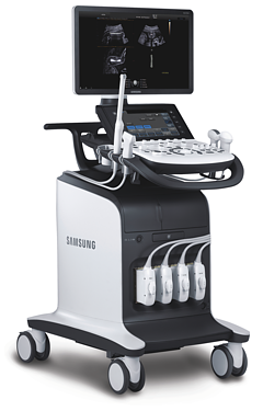
HS70A-RUS — ультразвуковой сканер экспертного класса производства компании Samsung Medison с поддержкой технологий для оптимизации и увеличения диагностической точности исследований, от рутинных до самых сложных.
В системе интегрированы инновационные алгоритмы «машинного обучения» с поддержкой принятия решений начинающими специалистами (стандартизированное описание образований молочной и щитовидной железы в S-Detect), 5D (акушерство и гинекология), ElastoScan, E-Breast, E-Thyroid и S-Sharewave (эластография, дифференциальная диагностика в онкологии и общей радиологии), Arterial Analysis, Strain+ и StressEcho (ранняя диагностика сердечно-сосудистых заболеваний), CEUS+ (исследования с контрастными агентами). Аппарат рекомендован для использования в диагностических центрах, многопрофильных и специализированных медицинских учреждениях, медицинских исследовательских институтах.
Область исследований: абдоминальные исследования, акушерство и гинекология, кардиология, ангиология, нефрология, урология, онкология, педиатрия, неонатология, исследования поверхностных органов и костно-мышечной системы, молочной железы, транскраниальные исследования, чреспищеводная эхокардиография.
Базовая комплектация: сканер HS70A-RUS (монитор 23″; 4 активных порта для подключения визуализирующих датчиков; встроенные модули: цветного, энергетического, направленного энергетического и импульсно-волнового доплера, тканевого доплера; тканевая гармоника S-Harmonic; технология интерактивной коррекции изображений с помощью программного обеспечения магнитно-резонансной томографии ClearVision; пространственный компаундинг Multivision; автоматическая оптимизация QuickScan в В-режиме и режиме доплера (ЦДК, PW, CW); модуль улучшенной визуализации биопсийной иглы Needle Mate; программируемые протоколы исследования EZ-Exam; 8 USB-портов; сенсорная панель управления) и руководство по эксплуатации на русском языке.
Опции для сканера HS70A-RUS: кардиопакет, Smart 4D (3D + SFVI, FAD, VSI, Smooth Cut + 4D + 3DXI + 3DMXI), STIC, HDVI, FRV, 2D NT, 5D NT, 5D LB, 5D CNS, 5D Follicle, ElastoScan, E-Breast, E-Thyroid, S-Sharewave, S-Detect for Breast, S-Detect for Thyroid, CEUS+, Arterial Analysis, AutoIMT+, Strain+, StressEcho, ЭКГ модуль, модуль панорамного сканирования, DICOM, ADVR, подогреватель геля, ножная педаль управления.
Основные характеристики сканера HS70A-RUS
Стационарный ультразвуковой сканер.
LED монитор — 23″ (с диодной подсветкой, разрешение 1920×1080).
Сенсорная панель управления (touch-screen) 10″.
Разъемы для одновременного подключения до 5 датчиков (4 + 1 CW).
USB-порты (для подключения периферических устройств, внешних накопителей: флеш-карт или DVD).
Кинопамять — автоматическая видео-запись фрагмента исследования с возможностями «перемотки», редактирования, проведения расчетов и последующей записи видео в файл.
Модуль ClearVision — фильтрация изображения в реальном времени: удаляет спекл-шумы и артефакты, усиливает контуры, делая ультразвуковое изображение контрастней на границе сред разной эхо-плотности.
Модуль MultiVision — детализация изображения и уменьшение артефактов за счет технологии получения изображения с учетом нескольких углов инсонации.
Система SonoView — система архивации и дальнейшего просмотра статических и динамических изображений (база данных изображений), имеется возможность копирования изображений на внешние накопители (подключение по USB), проводить измерения в архиве.
Режимы визуализации
B (2D) — двухмерное сканирование в оттенках серой шкалы, тканевая гармоника (в том числе пульс-инверсная).
M — одномерный режим для исследования сердца, анатомический М-режим (необходим кардиопакет), CM — цветной М-режим (необходим кардиопакет).
CD — цветное допплеровское картирование с возможностью изменения допплеровского угла.
PD — энергетический допплер с возможностью изменения допплеровского угла.
DPDI — двунаправленный энергетический допплер.
TDI — тканевый допплер (необходим кардиопакет).
PW — импульсно-волновой допплер, steering — изменение допплеровского угла в режимах CD и PD, автоматический анализ допплеровских кривых.
HPRF — высокочастотный импульсно-волновой допплер.
CW — постоянно-волновой допплер (опция).
3D — трехмерное сканирование объемными датчиками в статическом режиме в серой шкале и восстановление объемной структуры сосудов в режиме цветного / энергетического допплера.
4D — трехмерное сканирование объемными датчиками в реальном масштабе времени.
Режимы одновременного отображения на экране 2-х, 4-х и более изображений, в т.ч. изображений в режимах B/C, B/PD в реальном масштабе времени.
Смешанные режимы (B/M, B/PWD, B/C, B/PD, B/PD/PWD, B/C/PWD).
Трапециевидный режим (для линейных датчиков).
Масштабирование.
Опции
Пакет опций объемного сканирования Smart 4D.
Модуль XI STIC объёмной динамической визуализации сердца плода.
Модуль HDVI — повышение четкости изображения границ тканей с разной эхо-плотностью в объемном изображении (диагностика тонких повреждений тканей, дефектов мозга плода, стенок и клапанов сердца плода).
Модуль Realistic Vue — программа реконструкции объемного изображения с возможностью перемещения виртуального источника освещения. Специальный процессинговый алгоритм воспроизводит трехмерную анатомию плода с исключительной детализацией.
Модуль 2D NT — программа автоматического измерения ТВП плода в режиме 2D.
Модуль 5D NT — программа автоматического измерения ТВП и интракраниального пространства плода в режиме объемного сканирования.
Модуль 5D LB — программа автоматического определения и измерения длинных костей плода в режиме объемного сканирования.
Модуль 5D CNS — программа автоматического получения 6 стандартных поскостей головного мозга плода и последующих автоматических измерений стандартных параметров фетометии головного мозга плода из объемных данных.
Модуль 5D Follicle — программа автоматического определения и измерения размера и объема фолликулов в режиме объемного сканирования.
Модуль ElastoScan — программы эластографии (качественная оценка) для исследований щитовидной железы, молочной железы у женщин и предстательной железы у мужчин.
Модуль E-Breast — программа автоматической количественной оценки эластичности тканей по выбранной зоне (необходим модуль Elastoscan).
Модуль E-Thyroid — программа сравнительной количественной оценки эластичности тканей (необходим модуль Elastoscan) без компрессии.
Модуль S-Sharewave — программа эластографии печени (сдвиговой волны), позволяющая автоматически определять индекс жесткости различных участков печени в кПа или м/с, получая при этом еще и индекс достоверности данных RMI.
Модуль S-Detect Breast — программа автоматического обнаружения и анализа образований молочной железы у женщин, измерение и классификация по системе BI-RADS.
Модуль S-Detect Thyroid — программа автоматического обнаружения образований и анализа щитовидной железы, измерение и классификация по системе TI-RADS (K-TIRADS, RUSS, ATA).
Модуль CEUS+ (Contrast Enchansment UltraSound) — исследования с применением контрастных веществ.
Кардиопакет: постоянно-волновой доплер CW + порт для карандашных датчиков + пакет кардиологических расчетов.
Модуль Arterial Analysis — программа, позволяющая автоматически провести анализ толщины и эластичности стенок разных участков сонной артерии, с выведением результатов в графической форме в движении (кинопетле) аналогично программе Strain для эхокардиографии.
Модуль Auto IMT+ автоматического расчета комплекса интима-медиа. Данная оценка имеет большое значение для ранней диагностики атеросклероза и оценки риска развития инсульта и инфаркта миокарда.
Модуль Strain+ автоматической количественной оценки сократимости миокарда ЛЖ.
Модуль Stress Echo.
Модуль ЭКГ.
Модуль панорамного сканирования.
Модуль DICOM — возможность сетевой интеграции с PACS-системами (например, для архивации или печати ультразвуковых эхограмм на оборудовании других производителей медтехники).
Модуль ADVR — программа записи исследования на флеш-карту (подключение по USB) в режиме реального времени.
Педаль дистанционного управления, 3 переключателя.
Подогреватель геля.
Пакет Smart 4D
Система Static 3D — трехмерное сканирование объемными датчиками в статическом режиме в серой шкале и восстановление объемной структуры сосудов в режиме цветного / энергетического допплера).
Система Live 3D — трехмерное сканирование объемными датчиками в реальном масштабе времени (4D).
Модуль SFVI.
Модуль FAD.
Модуль VSI.
Модуль Smooth Cut.
Пакет 3DXI.
Пакет 3DMXI.
Пакет 3D XI (объемная ультразвуковая томография)
MSV (Multi-Slice View или мультислайсинг) — возможность одновременного просмотра на экране множественных срезов, полученных при трехмерном сканировании.
VolumeCT — трехмерная реконструкция изображений в виде куба (Cube Sectional View) или трех пересекающихся плоскостей (Cross View).
OVIX (Oblique View eXtended) — получение фрагмента трехмерного изображения (в виде нескольких полупрозрачных сканов, последовательно наложенных один на другой) в направлении произвольного косого среза трехмерного объекта исследования.
Пакет 3D MXI (мульти-объемная ультразвуковая томография)
Multi Volume Slice — одновременный просмотр на экране нескольких объемных срезов трехмерного объекта исследования.
Mirror View (зеркальный режим) — режим отображения трехмерного объекта исследования, при котором одновременно представлены трехмерные изображения спереди, слева, справа и сверху.
Multi OVIX — одновременный просмотр на экране нескольких изображений OVIX, полученных из трехмерного объекта исследования.
Инновационные технологии
S-Vue датчики — некоторые датчики имеют улучшенный монокристаллический тип пьезоэлементов (технология изготовления пьезоэлементов из выращенных монокристаллов).
Quick Scan — режим автоматической настройки изображения (нажатием одной кнопки) исследуемого органа в B-, C и D-режиме (настройка оптимальных параметров и фильтров за счет автоматического распознавания исследуемого органа по интеллектуальной базе данных человеческих органов).
S-Harmonic — улучшенный вариант тканевой гармоники, повышающий качество визуализации глубоко расположенных структур.
ClearVision — технология интерактивной коррекции изображений с помощью программного обеспечения магнитно-резонансной томографии устраняет нежелательные артефакты в виде спекл-шумов, усиливая контрастное разрешение и четкость контуров, что кардинально улучшает качество изображения.
MultiVision — сложносоставное многолучевое сканирование обеспечивает снижение уровня шумов и четкие контуры границ раздела структур и тканей.
VSI (Volume Shade Imaging) — «визуализация объемных оттенков» на 3D-изображении.
FAD (Face Automatic Detection) — автоматическое определение лица плода в режиме Static 3D.
SFVI™ (Smart Filter Volume Imaging) — технология фильтрации 3D изображения (нажатием одной кнопки).
S-Flow — технология цветового допплеровского картирования с повышенной чувствительностью.
EZ Exam — программа протоколирования этапов ультразвукового исследования с последующим включением необходимых режимов при проведении исследования.
S-Vision — формирователь луча нового поколения, позволяющий снизить шумы, повысить четкость и глубину ультразвукового изображения.
Needle Mate — программа улучшения визуализации биопсийной иглы за счет увеличения ее контрастности на экране и изменения угла сканирования линейного датчика (Beam Steering).
Основные измерения
B-режим: расстояние, периметр, угол, площадь, эллипс, окружность, объем.
D-режим: скорость, давление, ускорение, замедление.
M-режим: время, расстояние, уклон.
Пакеты расчетов (измерения и отчеты)
Гинекология: матка, левый и правый яичники, левый и правый фолликулы, левая и правая яичниковые артерии, левая и правая маточные артерии, эндометрий, киста, опухоль, объемное образование и др.
Акушерство: биометрия плода (плодное яйцо (GS), теменно-копчиковая длина (CRL), бипариетальный размер головки (BPD), лобно-затылочное расстояние (OFD), окружности головы (НC), передне-задний размер живота (APD), поперечный размер живота (TAD), окружность живота (AC), длина бедра (FL) и др.), длинные кости плода (плечевая (Humerus), локтевая (Ulna), лучевая (Rad), большеберцовая (Tibia), малая берцовая, ключица (Clav) и позвоночник (LV), краниологическое исследование плода (мозжечок (CEREB), внешнее (OOD) и внутреннее (IOD) межглазничные расстояния, большая цистерна, шейная складка, боковые желудочки, носовая кость), другие показатели плода (ступня, ухо, средняя фаланга, почки, таз), индекс околоплодных вод (AFI), допплерометрия (пупочная артерия, средняя мозговая артерия, маточные артерии, плацентарная артерия, сонные артерии, аорта плода, венозный проток, ЧСС плода); уравнения для оценки веса плода (Хедлок (Hadlock) 1-4, Хансман (Hansmann) и Мерц (Merz)); таблицы, определяемые пользователем.
Сердце плода: измерения в В-режиме (отношение площади сердца и грудной клетки), измерения в М-режиме (толщина межжелудочковой перегородки в диастолу, конечнодиастолический размер левого желудочка, толщина задней стенки левого желудочка в диастолу, толщина межжелудочковой перегородки в систолу, размер левого желудочка в систолу, толщина задней стенки левого желудочка в систолу, внутренний размер правого желудочка в диастолу), измерения в режиме спектрального допплера (легочный ствол, артериальный проток, нижняя полая вена, венозный проток, восходящая аорта, нисходящая аорта, трансмитральный кровоток, митральная регургитация, трикуспидальный кровоток, трикуспидальная регургитация, индекс преднагрузки, ЧСС).
Пакет кардиологических исследований.
М-режим: измерение диаметра аорты, передне-заднего размера ЛП, толщины МЖП (систолическая и диастолическая), толщины ЗСЛЖ (систолическая и диастолическая), размеров ЛЖ и ПЖ (систолический и диастолический), ФВ (Teichholz).
B-режим: измерение диаметра аорты (восходящей, дуги, нисходящей, на уровне синусов Вальсальвы, на уровне створок аортального клапана), определение размеров ЛП и ПП (максимальный, минимальный, систолический, диастолический, переднее-задний, верхнее-нижний, медиально-латеральный), расчет объемов ЛП и ПП, объемов ЛЖ (метод «Площадь-Длина», метод дисков (Simpson)), массы миокарда ЛЖ, индекса массы миокарда ЛЖ.
CD-режим (ЦДК): измерение радиуса ПФСМР (PISA), полуколичественная оценка трансмитрального, транстрикуспидального, трансаортального и транспульмонального кровотока (оценка регургитации), оценка аномальных сбросов крови через МПП И МЖП.
PW-режим (импульсно-волновой допплер): автоматическая, полуавтоматическая и ручная трассировка допплеровского спектра митрального, аортального и трикуспидального клапанов, клапана легочной артерии, кровотока в выходном тракте ЛЖ и ПЖ (пиковая/средняя скорость, пиковый/средний градиент давления, время изоволюметрического расслабления ЛЖ, время ускорения, замедления, выброса), оценка кровотока легочных и печеночных вен.
CW-режим (постоянно-волновой допплер): программы расчета работы митрального, аортального и трикуспидального клапанов, клапана легочной артерии.
TD-режим (тканевой допплер): количественная оценка локальной сократительной функции стенок ЛЖ и ПЖ.
Сонные артерии: автоматическая, полуавтоматическая, ручная трассировка доплеровского спектра; ПСС, КДС, %СтПлощ, %Ст Диам, площадь сосуда, диаметр сосуда, средняя толщина интимы, объемный кровоток.
Артерии верхних конечностей: автоматическая, полуавтоматическая, ручная трассировка доплеровского спектра; ПСС, КДС, %СтПлощ, %Ст Диам, площадь сосуда, диаметр сосуда, объемный кровоток.
Артерии нижних конечностей: автоматическая, полуавтоматическая, ручная трассировка доплеровского спектра; ПСС, КДС, %СтПлощ, %Ст Диам, площадь сосуда, диаметр сосуда, объемный кровоток.
Вены нижних конечностей: автоматическая, полуавтоматическая, ручная трассировка доплеровского спектра; максимальная скорость, диаметр сосуда.
Сосуды брюшной полости: автоматическая, полуавтоматическая, ручная трассировка доплеровского спектра; ПСС, КДС, %СтПлощ, %Ст Диам, площадь сосуда, диаметр сосуда, объемный кровоток.
Урология: объем мочевого пузыря, остаточный объем, объем предстательной железы по WG, объем Т-зон, объем почки (методы измерения объема: три расстояния, три расстояния и коэффициент, эллипсоид).
Датчики для сканера HS70A-RUS
Конвексные датчики
Внутриполостной датчик EA2-11B (2-11 МГц, угол обзора 150°)
Клиническое применение: акушерство, гинекология, урология.
Биопсийный набор: нет.
Внутриполостной датчик VR5-9 (5-9 МГц, угол обзора 150°)
Клиническое применение: гинекология, акушерство, урология.
Биопсийный набор: есть.
Конвексный датчик CA1-7A (1-7 МГц, угол обзора 70°, монокристальный)
Клиническое применение: брюшная полость, акушерство, гинекология. Использование при работе с контрастом.
Биопсийный набор: есть.
Конвексный датчик CA2-8A (2-8 МГц, угол обзора 58°)
Клиническое применение: брюшная полость, гинекология, акушерство.
Биопсийный набор: есть.
Конвексный датчик CA2-9A (2-9 МГц, монокристальный)
Клиническое применение: брюшная полость, акушерство, гинекология.
Биопсийный набор: есть.
Конвексный датчик CA3-10A (3-10 МГц, монокристальный)
Клиническое применение: брюшная полость, акушерство, гинекология, педиатрия.
Биопсийный набор: нет.
Микроконвексный неонатальный датчик CF4-9 (4-9 МГц, угол обзора 90°)
Клиническое применение: педиатрия, сосуды.
Биопсийный набор: нет.
Фазированные датчики
Секторный фазированный датчик PA1-5A (1-5 МГц, монокристальный)
Клиническое применение: кардиология, транскраниальные исследования, брюшная полость.
Биопсийный набор: нет.
Секторный фазированный датчик PA3-8B (3-8 МГц)
Клиническое применение: кардиология у детей и новорожденных, транскраниальные исследования.
Биопсийный набор: нет.
Секторный фазированный датчик PA4-12B (4-12 МГц)
Клиническое применение: кардиология у новорожденных и детей.
Биопсийный набор: есть.
Секторный фазированный датчик PE2-4 (2-4 МГц)
Клиническое применение: кардиология, транскраниальные исследования, брюшная полость.
Биопсийный набор: нет.
Линейные датчики
Линейный датчик L3-12A (3-12 МГц, апертура 50 мм)
Клиническое применение: мышечно-скелетные исследования, поверхностно расположенные структуры, периферические сосуды.
Биопсийный набор: есть.
Линейный датчик LA2-9A (2-9 МГц, апертура 44 мм)
Клиническое применение: поверхностно расположенные структуры, периферические сосуды, мышечно-скелетные исследования, брюшная полость.
Биопсийный набор: есть.
Линейный датчик LA3-16A (3-16 МГц, апертура 40 мм)
Клиническое применение: мышечно-скелетные исследования, поверхностно расположенные структуры, периферические сосуды.
Биопсийный набор: есть.
Линейный датчик LA4-18B (4-18 МГц, апертура 37 мм)
Клиническое применение: поверхностно расположенные структуры, периферические сосуды, мышечно-скелетные исследования.
Биопсийный набор: есть.
Линейный датчик LM4-15B (4-15 МГц, апертура 50 мм, матричный)
Клиническое применение: поверхностно расположенные структуры, периферические сосуды, мышечно-скелетные исследования.
Биопсийный набор: есть.
Интраоперационные датчики
Линейный интраоперационный датчик LA3-16AI (3-16 МГц, Г-образный)
Клиническое применение: поверхностно расположенные структуры.
Биопсийный набор: нет.
Объемные датчики
Объемный внутриполостной датчик V5-9 (5-9 МГц)
Клиническое применение: акушерство, гинекология, урология.
Биопсийный набор: есть.
Объемный конвексный датчик CV1-8A (1-8 МГц, монокристальный)
Клиническое применение: брюшная полость, гинекология, акушерство.
Биопсийный набор: есть.
Объемный линейный датчик LV3-14A (3-14 МГц)
Клиническое применение: мышечно-скелетные исследования, поверхностно расположенные структуры, периферические сосуды.
Биопсийный набор: есть.
Чреспищеводные датчики
Чреспищеводный датчик MMPT3-7 (3-7 МГц, фазированный)
Клиническое применение: чреспищеводная эхокардиография.
Биопсийный набор: нет.
Допплеровские датчики
Допплеровский датчик DP2B (2 МГц, карандашный)
Клиническое применение: транскраниальные исследования, сосуды.
Биопсийный набор: нет.
Допплеровский датчик DP8B (8 МГц, карандашный)
Клиническое применение: транскраниальные исследования, сосуды.
Биопсийный набор: нет.
Описание
HS70A-RUS- ультразвуковой сканер экспертного класса производства компании Samsung Medison с поддержкой технологий для оптимизации и увеличения диагностической точности исследований, от рутинных до самых сложных.В системе интегрированы инновационные алгоритмы «машинного обучения» с поддержкой принятия решений начинающими специалистами (стандартизированное описание образований молочной и щитовидной железы в S-Detect), 5D (акушерство и гинекология), ElastoScan, E-Breast, E-Thyroid и S-Sharewave (эластография, дифференциальная диагностика в онкологии и общей радиологии), Arterial Analysis, Strain+ и StressEcho (ранняя диагностика сердечно-сосудистых заболеваний), CEUS+ (исследования с контрастными агентами). Аппарат рекомендован для использования в диагностических центрах, многопрофильных и специализированных медицинских учреждениях, медицинских исследовательских институтах.
Область исследований: абдоминальные исследования, акушерство и гинекология, кардиология, ангиология, нефрология, урология, онкология, педиатрия, неонатология, исследования поверхностных органов и костно-мышечной системы, молочной железы, транскраниальные исследования, чреспищеводная эхокардиография.
Опции для сканера HS70A-RUS:
кардиопакет, Smart 4D (3D + SFVI, FAD, VSI, Smooth Cut + 4D + 3DXI + 3DMXI), STIC, HDVI, FRV, 2D NT, 5D NT, 5D LB, 5D CNS, 5D Follicle, ElastoScan, E-Breast, E-Thyroid, S-Sharewave, S-Detect for Breast, S-Detect for Thyroid, CEUS+, Arterial Analysis, AutoIMT+, Strain+, StressEcho, ЭКГ модуль, модуль панорамного сканирования, DICOM, ADVR, Mobile Export, подогреватель геля, ножная педаль управления.
Режимы визуализации
- B (2D) — двухмерное сканирование в оттенках серой шкалы,тканевая гармоника(в том числе пульс-инверсная).
- M — одномерный режим для исследования сердца, анатомический М-режим (необходим кардиопакет), CM — цветной М-режим (необходим кардиопакет).
- CD — цветное допплеровское картирование с возможностью изменения допплеровского угла.
- PD — энергетический допплер с возможностью изменения допплеровского угла.
- DPDI — двунаправленный энергетический допплер.
- TDI- тканевый допплер (необходим кардиопакет).
- PW — импульсно-волновой допплер, steering — изменение допплеровского угла в режимах CD и PD, автоматический анализ допплеровских кривых.
- HPRF- высокочастотный импульсно-волновой допплер.
- CW — постоянно-волновой допплер (опция).
- 3D — трехмерное сканирование объемными датчиками в статическом режиме в серой шкале и восстановление объемной структуры сосудов в режиме цветного / энергетического допплера.
- 4D — трехмерное сканирование объемными датчиками в реальном масштабе времени.
- Режимы одновременного отображения на экране 2-х, 4-х и более изображений, в т.ч. изображений в режимах B/C, B/PD в реальном масштабе времени.
- Смешанные режимы (B/M, B/PWD, B/C, B/PD, B/PD/PWD, B/C/PWD).
- Трапециевидный режим (для линейных датчиков).
- Масштабирование.
Опции
- Пакет опций объемного сканирования Smart 4D.
- Модуль XISTICобъёмной динамической визуализации сердца плода.
- Модуль HDVI — повышение четкости изображения границ тканей с разной эхо-плотностью в объемном изображении (диагностика тонких повреждений тканей, дефектов мозга плода, стенок и клапанов сердца плода).
- МодульRealistic Vue- программа реконструкции объемного изображения с возможностью перемещения виртуального источника освещения. Специальный процессинговый алгоритм воспроизводит трехмерную анатомию плода с исключительной детализацией.
- Модуль 2D NT — программа автоматического измерения ТВП плода в режиме 2D.
- Модуль 5D NT — программа автоматического измерения ТВП и интракраниального пространства плода в режиме объемного сканирования.
- Модуль 5D LB — программа автоматического определения и измерения длинных костей плода в режиме объемного сканирования.
- Модуль 5D CNS — программа автоматического получения 6 стандартных поскостей головного мозга плода и последующих автоматических измерений стандартных параметров фетометии головного мозга плода из объемных данных.
- Модуль 5D Follicle — программа автоматического определения и измерения размера и объема фолликулов в режиме объемного сканирования.
- Модуль ElastoScan — программы эластографии (качественная оценка) для исследований щитовидной железы, молочной железы у женщин и предстательной железы у мужчин.
- МодульE-Breast- программа автоматической количественной оценки эластичности тканей по выбранной зоне (необходим модуль Elastoscan).
- МодульE-Thyroid- программа сравнительной количественной оценки эластичности тканей (необходим модуль Elastoscan) без компрессии.
- Модуль S-Sharewave — программа эластографии печени (сдвиговой волны), позволяющая автоматически определять индекс жесткости различных участков печени в кПа или м/с, получая при этом еще и индекс достоверности данных RMI.
- МодульS-Detect Breast- программа автоматического обнаружения и анализа образований молочной железы у женщин, измерение и классификация по системе BI-RADS.
- МодульS-Detect Thyroid- программа автоматического обнаружения образований и анализа щитовидной железы, измерение и классификация по системе TI-RADS (K-TIRADS, RUSS, ATA).
- Модуль CEUS+ (Contrast Enchansment UltraSound) — исследования с применением контрастных веществ.
- Кардиопакет: постоянно-волновой доплер CW + порт для карандашных датчиков + пакет кардиологических расчетов.
- Модуль Arterial Analysis — программа, позволяющая автоматически провести анализ толщины и эластичности стенок разных участков сонной артерии, с выведением результатов в графической форме в движении (кинопетле) аналогично программе Strain для эхокардиографии.
- Модуль Auto IMT+ автоматического расчета комплекса интима-медиа. Данная оценка имеет большое значение для ранней диагностики атеросклероза и оценки риска развития инсульта и инфаркта миокарда.
- Модуль Strain+ автоматической количественной оценки сократимости миокарда ЛЖ.
- Модуль Stress Echo.
- Модуль ЭКГ.
- Модуль панорамного сканирования.
- Модуль DICOM — возможность сетевой интеграции с PACS-системами (например, для архивации или печати ультразвуковых эхограмм на оборудовании других производителей медтехники).
- Модуль ADVR — программа записи исследования на DVD в режиме реального времени.
- Модуль Mobile Export беспроводной передачи данных УЗ исследования на мобильные устройства (Необходим модуль ADVR, адаптер Wi-Fi, приложение Hello Mom).
- Педаль дистанционного управления, 3 переключателя.
- Подогреватель геля.
Пакет Smart 4D
- Система Static 3D — трехмерное сканирование объемными датчиками в статическом режиме в серой шкале и восстановление объемной структуры сосудов в режиме цветного / энергетического допплера).
- СистемаLive 3D- трехмерное сканирование объемными датчиками в реальном масштабе времени (4D).
- Модуль SFVI.
- Модуль FAD.
- Модуль VSI.
- Модуль Smooth Cut.
- Пакет 3DXI.
- Пакет 3DMXI.
Пакет 3D XI (объемная ультразвуковая томография)
- MSV(Multi-Slice View илимультислайсинг) — возможность одновременного просмотра на экране множественных срезов, полученных при трехмерном сканировании.
- VolumeCT — трехмерная реконструкция изображений в виде куба (Cube Sectional View) или трех пересекающихся плоскостей (Cross View).
- OVIX(Oblique View eXtended) — получение фрагмента трехмерного изображения (в виде нескольких полупрозрачных сканов, последовательно наложенных один на другой) в направлении произвольного косого среза трехмерного объекта исследования.
Пакет 3D MXI (мульти-объемная ультразвуковая томография)
- Multi Volume Slice- одновременный просмотр на экране нескольких объемных срезов трехмерного объекта исследования.
- Mirror View(зеркальный режим) — режим отображения трехмерного объекта исследования, при котором одновременно представлены трехмерные изображения спереди, слева, справа и сверху.
- Multi OVIX — одновременный просмотр на экране нескольких изображений OVIX, полученных из трехмерного объекта исследования.
Инновационные технологии
- S-Vue датчики — некоторые датчики имеют улучшенный монокристаллический тип пьезоэлементов (технология изготовления пьезоэлементов из выращенных монокристаллов).
- Quick Scan — режим автоматической настройки изображения (нажатием одной кнопки) исследуемого органа в B-, C и D-режиме (настройка оптимальных параметров и фильтров за счет автоматического распознавания исследуемого органа по интеллектуальной базе данных человеческих органов).
- S-Harmonic — улучшенный варианттканевой гармоники, повышающий качество визуализации глубоко расположенных структур.
- ClearVision — технология интерактивной коррекции изображений с помощью программного обеспечения магнитно-резонансной томографии устраняет нежелательные артефакты в виде спекл-шумов, усиливая контрастное разрешение и четкость контуров, что кардинально улучшает качество изображения.
- MultiVision — сложносоставное многолучевое сканирование обеспечивает снижение уровня шумов и четкие контуры границ раздела структур и тканей.
- VSI (Volume Shade Imaging) — «визуализация объемных оттенков» на 3D-изображении.
- FAD (Face Automatic Detection) — автоматическое определение лица плода в режиме Static 3D.
- SFVI™ (Smart Filter Volume Imaging) — технология фильтрации 3D изображения (нажатием одной кнопки).
- S-Flow — технология цветового допплеровского картирования с повышенной чувствительностью.
- EZ Exam — программа протоколирования этапов ультразвукового исследования с последующим включением необходимых режимов при проведении исследования.
- S-Vision — формирователь луча нового поколения, позволяющий снизить шумы, повысить четкость и глубину ультразвукового изображения.
- Needle Mate — программа улучшения визуализации биопсийной иглы за счет увеличения ее контрастности на экране и изменения угла сканирования линейного датчика (Beam Steering).
Основные измерения
- B-режим: расстояние, периметр, угол, площадь, эллипс, окружность, объем.
- D-режим: скорость, давление, ускорение, замедление.
- M-режим: время, расстояние, уклон.
Пакеты расчетов (измерения и отчеты)
- Гинекология:матка, левый и правый яичники, левый и правый фолликулы, левая и правая яичниковые артерии, левая и правая маточные артерии, эндометрий, киста, опухоль, объемное образование и др.
- Акушерство:биометрия плода (плодное яйцо (GS), теменно-копчиковая длина (CRL), бипариетальный размер головки (BPD), лобно-затылочное расстояние (OFD), окружности головы (НC), передне-задний размер живота (APD), поперечный размер живота (TAD), окружность живота (AC), длина бедра (FL) и др.), длинные кости плода (плечевая (Humerus), локтевая (Ulna), лучевая (Rad), большеберцовая (Tibia), малая берцовая, ключица (Clav) и позвоночник (LV), краниологическое исследование плода (мозжечок (CEREB), внешнее (OOD) и внутреннее (IOD) межглазничные расстояния, большая цистерна, шейная складка, боковые желудочки, носовая кость), другие показатели плода (ступня, ухо, средняя фаланга, почки, таз), индекс околоплодных вод (AFI), допплерометрия (пупочная артерия, средняя мозговая артерия, маточные артерии, плацентарная артерия, сонные артерии, аорта плода, венозный проток, ЧСС плода); уравнения для оценки веса плода (Хедлок (Hadlock) 1-4, Хансман (Hansmann) и Мерц (Merz)); таблицы, определяемые пользователем.
- Сердце плода:измерения в В-режиме (отношение площади сердца и грудной клетки), измерения в М-режиме (толщина межжелудочковой перегородки в диастолу, конечнодиастолический размер левого желудочка, толщина задней стенки левого желудочка в диастолу, толщина межжелудочковой перегородки в систолу, размер левого желудочка в систолу, толщина задней стенки левого желудочка в систолу, внутренний размер правого желудочка в диастолу), измерения в режиме спектрального допплера (легочный ствол, артериальный проток, нижняя полая вена, венозный проток, восходящая аорта, нисходящая аорта, трансмитральный кровоток, митральная регургитация, трикуспидальный кровоток, трикуспидальная регургитация, индекс преднагрузки, ЧСС).
- Пакет кардиологических исследований.
М-режим:измерение диаметра аорты, передне-заднего размера ЛП, толщины МЖП (систолическая и диастолическая), толщины ЗСЛЖ (систолическая и диастолическая), размеров ЛЖ и ПЖ (систолический и диастолический), ФВ (Teichholz).
B-режим:измерение диаметра аорты (восходящей, дуги, нисходящей, на уровне синусов Вальсальвы, на уровне створок аортального клапана), определение размеров ЛП и ПП (максимальный, минимальный, систолический, диастолический, переднее-задний, верхнее-нижний, медиально-латеральный), расчет объемов ЛП и ПП, объемов ЛЖ (метод «Площадь-Длина», метод дисков (Simpson)), массы миокарда ЛЖ, индекса массы миокарда ЛЖ.
CD-режим (ЦДК):измерение радиуса ПФСМР (PISA), полуколичественная оценка трансмитрального, транстрикуспидального, трансаортального и транспульмонального кровотока (оценка регургитации), оценка аномальных сбросов крови через МПП И МЖП.
PW-режим (импульсно-волновой допплер):автоматическая, полуавтоматическая и ручная трассировка допплеровского спектра митрального, аортального и трикуспидального клапанов, клапана легочной артерии, кровотока в выходном тракте ЛЖ и ПЖ (пиковая/средняя скорость, пиковый/средний градиент давления, время изоволюметрического расслабления ЛЖ, время ускорения, замедления, выброса), оценка кровотока легочных и печеночных вен.
CW-режим (постоянно-волновой допплер):программы расчета работы митрального, аортального и трикуспидального клапанов, клапана легочной артерии.
TD-режим (тканевой допплер):количественная оценка локальной сократительной функции стенок ЛЖ и ПЖ. - Сонные артерии:автоматическая, полуавтоматическая, ручная трассировка доплеровского спектра; ПСС, КДС, %СтПлощ, %Ст Диам, площадь сосуда, диаметр сосуда, средняя толщина интимы, объемный кровоток.
- Артерии верхних конечностей:автоматическая, полуавтоматическая, ручная трассировка доплеровского спектра; ПСС, КДС, %СтПлощ, %Ст Диам, площадь сосуда, диаметр сосуда, объемный кровоток.
- Артерии нижних конечностей:автоматическая, полуавтоматическая, ручная трассировка доплеровского спектра; ПСС, КДС, %СтПлощ, %Ст Диам, площадь сосуда, диаметр сосуда, объемный кровоток.
- Вены нижних конечностей:автоматическая, полуавтоматическая, ручная трассировка доплеровского спектра; максимальная скорость, диаметр сосуда.
- Сосуды брюшной полости:автоматическая, полуавтоматическая, ручная трассировка доплеровского спектра; ПСС, КДС, %СтПлощ, %Ст Диам, площадь сосуда, диаметр сосуда, объемный кровоток.
- Урология:объем мочевого пузыря, остаточный объем, объем предстательной железы по WG, объем Т-зон, объем почки (методы измерения объема: три расстояния, три расстояния и коэффициент, эллипсоид).
Сокращения:ЛП/ПП — левое/правое предсердие, МЖП — межжелудочковая перегородка, МПП — межпредсердная перегородка, ЗСЛЖ — задняя стенка левого желудочка, ЛЖ/ПЖ — левый/правый желудочек, ФВ — фракция выброса, ПФСМР — площадь формирующейся струи митральной регуритации (PISA — proximal isovelocity surface area), ПСС/КДС — пиковая систолическая / конечная диастолическая скорость.
Датчики для сканера HS70A-RUS
Конвексные датчики
Конвексный датчик 1-7 МГц (монокристальный)
Абдоминальные исследования (печень, желчный пузырь, поджелудочная железа, селезенка, глубоко расположенные сосуды), акушерские исследования (плод, сердце плода) и гинекология (матка, яичники).
Биопсийный набор: есть.
Конвексный датчик 2-11 МГц (ректо-вагинальный)
Акушерство (ранние сроки), гинекология (матка, яичники) и урология (предстательная железа).
Биопсийный набор: нет.
Конвексный датчик 2-8 МГц
Абдоминальные исследования (печень, желчный пузырь, поджелудочная железа, селезенка, глубоко расположенные сосуды), акушерские исследования (плод, сердце плода) и гинекология (матка, яичники).
Биопсийный набор: есть.
Конвексный датчик 2-9 МГц (монокристальный)
Абдоминальные исследования (печень, желчный пузырь, поджелудочная железа, селезенка, глубоко расположенные сосуды), акушерские исследования (плод, сердце плода), гинекология (матка, яичники).
Биопсийный набор: есть.
Конвексный датчик 3-10 МГц (монокристальный)
Абдоминальные исследования (печень, желчный пузырь, поджелудочная железа, селезенка, глубоко расположенные сосуды), акушерские исследования (плод, сердце плода), гинекология (матка, яичники), периферические сосуды и педиатрия.
Биопсийный набор: нет.
Конвексный датчик 3-12 МГц (ректо-вагинальный)
Акушерство (ранние сроки), гинекология (матка, яичники) и урология (предстательная железа).
Биопсийный набор: нет.
Конвексный датчик 4-9 МГц (неонатальный)
Неонатология и педиатрия: абдоминальные исследования, почки, сердце, глубоко расположенные сосуды и мозг.
Биопсийный набор: нет.
Конвексный датчик 5-9 МГц (вагинальный)
Акушерство (ранние сроки), гинекология (матка, яичники) и урология (предстательная железа).
Биопсийный набор: есть.
Биплановые датчики
Биплановый внутриполостной датчик 4-9 МГц
Исследование предстательной железы.
Биопсийный набор: есть.
Фазированные датчики
Фазированный датчик 2-4 МГц
Кардиология, транскраниальные и абдоминальные исследования (печень, желчный пузырь, поджелудочная железа, селезенка, глубоко расположенные сосуды).
Биопсийный набор: нет.
Фазированный датчик 3-8 МГц
Кардиология, транскраниальные и абдоминальные исследования (печень, желчный пузырь, поджелудочная железа, селезенка, глубоко расположенные сосуды), педиатрия.
Биопсийный набор: нет.
Фазированный датчик 4-12 МГц
Кардиология, абдоминальные исследования, неонаталогия.
Биопсийный набор: есть.
Линейные датчики
Линейный датчик 2-9 МГц
Глубоко расположенные сосуды, кишечник, щитовидная железа, молочная железа, лимфоузлы, абдоминальные исследования (печень, желчный пузырь, поджелудочная железа, селезенка) и скелетно-мышечная система (суставы, мышцы).
Биопсийный набор: нет.
Линейный датчик 3-12 МГц
Щитовидная железа, молочная железа, лимфоузлы, сосуды, акушерство и скелетно-мышечная система (суставы, мышцы, подкожные структуры).
Биопсийный набор: есть.
Линейный датчик 3-16 МГц
Щитовидная железа, молочная железа, лимфоузлы, периферические сосуды и скелетно-мышечная система (суставы, мышцы, подкожные структуры).
Биопсийный набор: нет.
Линейный датчик 4-18 МГц
Щитовидная железа, молочная железа, лимфоузлы, сосуды, акушерство, скелетно-мышечная система (суставы, мышцы, подкожные структуры).
Биопсийный набор: есть.
Интраоперационные датчики
Линейный датчик 3-16 МГц (интраоперационный)
Скелетно-мышечная система (суставы, мышцы, подкожные структуры), интраоперационные исследования.
Биопсийный набор: нет.
Объемные датчики
Объемный датчик 1-8 МГц
Абдоминальные исследования (печень, желчный пузырь, поджелудочная железа, селезенка, глубоко расположенные сосуды), акушерские исследования (плод, сердце плода) и гинекология (матка, яичники).
Биопсийный набор: есть.
Объемный датчик 3-14 МГц
Скелетно-мышечная система (суставы, мышцы, подкожные структуры), поверхностно расположенные органы (щитовидная железа, молочная железа, лимфоузлы), сосуды.
Биопсийный набор: нет.
Объемный датчик 5-9 МГц (ректо-вагинальный)
Трехмерные исследования в акушерстве (ранние сроки), гинекологии (матка, яичники), урологии (предстательная железа).
Биопсийный набор: есть.
Чреспищеводные датчики
Чреспищеводный датчик 3-7 МГц (фазированный)
Чреспищеводная эхокардиография.
Биопсийный набор: нет.
Допплеровские датчики
Допплеровский датчик 2.0 МГц (слепой допплер)
Транскраниальные исследования, сосуды.
Биопсийный набор: нет.
Допплеровский датчик 8.0 МГц (слепой допплер)
Транскраниальные исследования, сосуды.
Биопсийный набор: нет.
ХАРАКТЕРИСТИКИ
- Стационарный ультразвуковой сканер.
- LED монитор — 23″ (с диодной подсветкой, разрешение 1920×1080).
- Сенсорная панель управления (touch-screen) 10″.
- Разъемы для одновременного подключения до 5 датчиков (4 + 1 CW).
- Встроенный дисковод DVD-RW.
- USB-порты (для подключения периферических устройств и внешних дисковых накопителей).
- Кинопамять — автоматическая видео-запись фрагмента исследования с возможностями «перемотки», редактирования, проведения расчетов и последующей записи видео в файл.
- Модуль ClearVision — фильтрация изображения в реальном времени: удаляет спекл-шумы и артефакты, усиливает контуры, делая ультразвуковое изображение контрастней на границе сред разной эхо-плотности.
- Модуль MultiVision — детализация изображения и уменьшение артефактов за счет технологии получения изображения с учетом нескольких углов инсонации.
- СистемаSonoView- система архивации и дальнейшего просмотра статических и динамических изображений (база данных изображений), имеется возможность копирования изображений на DVD и USB флеш-накопители, проводить измерения в архиве.
КОМПЛЕКТАЦИЯ
Базовая комплектация: сканер HS70A-RUS (монитор 23″; 4 активных порта для подключения визуализирующих датчиков; встроенные модули: цветного, энергетического, направленного энергетического и импульсно-волнового доплера, тканевого доплера; тканевая гармоника S-Harmonic; технология интерактивной коррекции изображений с помощью программного обеспечения магнитно-резонансной томографии ClearVision; пространственный компаундинг Multivision; автоматическая оптимизация QuickScan в В-режиме и режиме доплера (ЦДК, PW, CW); модуль улучшенной визуализации биопсийной иглы Needle Mate; программируемые протоколы исследования EZ-Exam; встроенный дисковод DVD-RW; 8 USB-портов; сенсорная панель управления) и руководство по эксплуатации на русском языке.
Содержание
- Описание и назначение аппарата HM70A;
- Отличительные особенности;
- Ключевые параметры;
- Видеопрезентация;
- Ближайшие конкуренты;
- Приобретение оборудования на выгодных условиях.

Описание и назначение оборудования
Переносной ультразвуковой сканер HM70A-RUS является высокоточным диагностическим устройством. Он обеспечивает визуализацию на уровне стационарных экспертных систем, обладает умеренной ценой и богатым функционалом.
Аппарат работает с высокоплотными монокристальными датчиками, задействуется при проведении 3D/4D-УЗИ, эластографии, Volume NT, STIC. С его помощью расширяются возможности мобильных госпиталей, спортивных медицинских бригад, экипажей скорой помощи.
Прибор имеет наименьшие габариты и вес в своем классе.
Переносные ультразвуковые сканеры HM70A востребованы в различных отраслях медицины:
- кардиология;
- чреспищеводная эхокардиография;
- поверхностные органы;
- абдоминальные исследования;
- онкология;
- урология;
- исследование сосудов;
- акушерство и гинекология.
Оборудование упрощает проведение инвазивных процедур, задействуется в педиатрии и неонатологии. Оно повышает точность диагностики опорно-двигательного аппарата.
Аппарат задействуется при организации скрининговых и расширенных экспертных исследований.
Отличительные особенности
В рамках HM70A реализовано свыше 10 прогрессивных решений, упрощающих проведение диагностических процедур.
Визуализация
- S—Flow. Технология работы с малыми кровеносными сосудами. Высокоточное картирование кровотока позволяет получить детальные снимки сложных участков, выявить патологию на ранней стадии.

Рис. Почка в режиме S-Flow.
- ClearVision. Анализ акустических свойств ткани, формирование контрастного изображения, лишенного шумов.
- Поддержка монокристальных датчиков различных типов. Работа с датчиками S-Vue, функционирующими в широком диапазоне частот. Модули обладают прекрасными пьезоэлектрическими свойствами, имеют увеличенную глубину сканирования.
Инвазивные процедуры по контролем УЗИ
- Needle Mate. Технология «подсветки» пункционной иглы, увеличивающая точность инвазивных манипуляций.
- EzAssist. Интерактивный ассистент, предоставляющий онлайн подсказки по ургентной медицине и ультразвуковому контролю инвазинвых процедур (блокада нервов, катетеризация сосудов, регионарная анастезия, FAST протокол и др.).
.jpg "EzAssist - встроенный в УЗ сканер Samsung Medison HM70A интерактивный помощник по ургентной медицине и УЗ контролю инвазивных процедур")
Рис. Процедура катетеризации внутренней яремной вены при поддержке онлайн помощника EzAssist Samsung.
Кардиология и сосуды
- Strain+. Прогрессивная методика, упрощающая количественную оценку сократимости левого желудочка. Расчеты проводятся в автоматическом режиме. Для начала процедуры специалисту требуется указать три контрольные точки.
- StressEcho. Инструмент для сравнительного анализа кинетики стенок желудочка. Исследования проводятся в спокойном и стрессовом состоянии, позволяют определить устойчивость к физической и фармакологической нагрузке.
- Auto IMT+. Модуль автоматического расчета ближней и дальней стенки сонной артерии. Он упрощает выполнение типовых операций, оценивает риск развития сердечно-сосудистых патологий.

Рис. Общая сонная артерия в режиме Auto IMT+.
Акушерство и гинекология
- 4D. Трехмерное сканирование посредством объемных датчиков. Изображение имеет реальный масштаб и высокую частоту кадров. Для проведения работ используются конвексные и внутриполосные 4D датчики.
.jpg "Плод, 2 триместр, в режиме 3D/4D / HM70A")
Рис. Плод (2-й триместр) в режиме 3D/4D.
- HDVI (High Definition Volume Imaging). Функция, востребованная при диагностике тонких повреждений ткани, исследовании мозга и стенок клапанов сердца плода. Она выделяет ткани различной плотности, минимизирует риск неточностей и ошибок.
- STIC. Технология динамической визуализации сердца пода. Изображение имеет высокую частоту кадров, обладает прекрасной четкостью.
- Volume NT и IT. Полуавтоматический алгоритм, облегчающий измерение толщины воротникового и интракраниального пространства плода. Процедура востребована при первичной диагностике синдрома Дауна и прочих серьезных заболеваний.
Мобильный ультразвуковой сканер HM70A широко применяется в онкологии. Экспертам доступна технология ElastoScan, предназначенная для изучения мягких тканей на предмет новообразований. Определить жесткость целевых фрагментов позволяет цветовая карта.

Рис. Образование в молочной железе в режиме ElastoScan.
Число доступных функций зависит от комплектности и модификации прибора.
Ключевые параметры
Сканер HM70A обладает следующими характеристиками:
- глубина сканирования – до 38 см;
- регулировка динамического диапазона – до 256 Дб;
- время выхода из спящего режима – до 25 сек;
- время автономной работы при использовании батареи увеличенной емкости – более 3-х часов;
- число портов для датчиков: 1 – в базовом исполнении, 3 – при использовании тележки;

Рис. Разветвитель портов до 3-х на тележке HM70A.
- штатный дисплей: 15 дюймов (1024х768 пикс) с возможностью полноэкранной визуализации объекта сканирования;
- масса – порядка 6 кг.
В продаже представлены устройства базовой и расширенной комплектации. Вместе с аппаратами реализуется множество дополнительных модулей.
Ближайшие конкуренты
Аналогами HM70A являются Logiq E (General Electric) и Philips CX 50.
| HM70A | Logiq E | CX50 | |
|---|---|---|---|
| Производитель | Samsung Medison | General Electric | Philips |
| Страна производства | Южная Корея | Китай | США |
| Размер монитора | 15″ | 15″ | 15″ |
| Тип монитора | Светодиодный | Жидкокристаличексий | Жидкокристалический |
| Руссифицированный интерфейс | + | + | + |
| Глубина сканирования | до 38 см | до 33 см | до 30 см |
| Частота кадров в базовых режимах | более 2000 кадров/сек | 1400 кадров/сек | 700 кадров/сек |
| Монокристальные датчики | S-Vue | — | PureWave |
| 3D/4D | + | — | — |
| Эластография | + | — | + |
| Оценка параметров сократимости ЛЖ (глобальный стрейн) | + | — | + |
| Матричные двумерные датчики | — | — | xMatrix |
| Визуализация сердца в режиме Live 3D | — | — | + |
| Количественный анализ в 3D для кардиологии | — | — | + |
Преимущества HM70A:
- Глубина сканирования. Консоли серии HM70A имеют наибольшую глубину сканирования. Они формируют качественные графические материалы, успешно решают типовые и нестандартные задачи.
- Частота кадров. Предельная частота кадров HM70A – более 2 000 в секунду. Это гарантирует получение плавного и четкого видеоряда. Аналогичный показатель у конкурентов на порядок ниже.
- Поддержка S—Vue. Поддержка монокристаллических датчиков расширяет функционал техники Samsung, улучшает качество снимков на 20%. Технология S-Vue не поддерживается Logiq E, представлена в ограниченном виде на Philips CX 50 (датчики PureWave).
- 4D-УЗИ. Уникальная функция, присутствующая только в аппарате Samsung. Технология помогает детально изучить плод, является привилегией экспертных сканеров стационарного типа. Наличие подобного решения на мобильном устройстве расширяет возможности диагностического кабинета, позволяет проводить качественные, скрупулезные исследования.
Недостаток HM70A – ограниченные возможности в премиальной кардиологии. Техника не способна визуализировать текстуры сердца в режиме Live 3D, а также выполнить количественный анализ полученных данных. Данный функционал – конек УЗИ систем Philips уровня High-end. Однако премиальные кардиологические функции очень дороги и практически не используются в повседневных исследованиях
Приобретение оборудования на выгодных условиях
Купить функциональный сканер HM70A поможет компания УЗИ МИР. Предприятие является официальным дилером Samsung, предлагает сертифицированные аппараты для коммерческих и государственных клиник.
Преимущества сотрудничества.
- Высокое качество продукции. Клиенты получают оригинальное оборудование, соответствующее отраслевым нормативам. Товар сопровождается сертификатами и паспортами, на него распространяется расширенная гарантия.
- «Обновленные демо». Некоторые аппараты предлагаются на льготных условиях. Эти устройства использовались на заводах концерна в демонстрационных целях. Они имеют прекрасное техническое состояние, полностью готовы к эксплуатации. Размер дисконта может достигать 70%.
- Прямое сотрудничество с поставщиком. Товар реализуется по оптовой цене, без комиссий и переплат. Предусмотрены существенные скидки, беспроцентные рассрочки, лизинговые программы.
- Доставка и установка. Подключение и настройку оборудования выполняют специалисты УЗИ МИР. Они производят первичное обучение персонала, дают рекомендации по дальнейшей эксплуатации техники.
Для оформления заявки на приобретение УЗИ-сканера воспользуйтесь телефоном 8 (800) 100-52-10 или закажите обратный звонок.