-
Contents
-
Table of Contents
-
Bookmarks
Quick Links
Shortmanual
EQJW146F001
P100019097
Heating and District Heating Controller
Firmwareversion 2.4x
Related Manuals for sauter EQJW146F001
Summary of Contents for sauter EQJW146F001
-
Page 1
Shortmanual EQJW146F001 P100019097 Heating and District Heating Controller Firmwareversion 2.4x… -
Page 2
Note on these mounting and operating instructions These mounting and operating instructions assist you in mounting and operating the device safely. The instructions are binding for handling SAUTER devices. Î For the safe and proper use of these instructions, read them carefully and keep them for later reference. -
Page 3: Table Of Contents
Communication …………… 27 Memory module …………….29 Installation …………….30 Electrical connection …………..32 Appendix …………….34 10.1 Function block lists …………….34 10.2 Parameter lists ………………45 10.3 Resistance values ……………… 51 10.4 Technical data ………………52 EQJW146F001 EN…
-
Page 4: Safety Instructions
Select a suitable disposal method. Instead, dispose of your waste equipment by handing it over to a designated collection point for the recycling of waste electrical and electronic equipment. EQJW146F001 EN…
-
Page 5: Operation
Information level, normal switch position Operating modes Manual level Day set point (rated room temperature, DHW tempera- ture) Night set point (reduced room temperature, DHW temperature sustaining value) Times-of-use for heating/DHW Party mode Controller time Parameter and configuration level EQJW146F001 EN…
-
Page 6: Operating Modes
6. Turn the rotary switch back to normal switch position (information level). Note In automatic operation, the current phase of the time program ( for day mode or night mode) is displayed in the information level together with the icon. EQJW146F001 EN…
-
Page 7: Display
Valve HC1 CLOSED Valve HC2 CLOSED Circulation pump (DHW) 1) UP1, UP2, TLP, CP, SLP and ZP indicate possible choices for pump selection in manual mode. Fig. 1: Icons The controller status can be displayed in the information level (see section 2.4). EQJW146F001 EN…
-
Page 8: Activate The Information Level
Temperature at storage tank sensor SF1 Temperature at storage tank sensor SF2 Temperature at storage tank sensor of solar circuit 2. Confirm a data point [Û] to read the associated set point/limit. The date is displayed when the time reading appears. EQJW146F001 EN…
-
Page 9: Setting The Time And Date
8. Turn the rotary switch back to normal switch position (information level). Note The correct time is guaranteed after a power failure of 24 hours. Normally, the correct time is still retained at least 48 hours after a power failure. EQJW146F001 EN…
-
Page 10: Setting The Times-Of-Use
3. Confirm the selected control circuit [Û]. If control circuit 1 or 2 has been selected, steps 4 and 5 are not required. 4. Configure DHW circuit [q]: DHW heating Circulation pump (DHW) 5. Confirm setting [Û]. EQJW146F001 EN…
-
Page 11
Note Do not use the 1–7 menu to check the programmed times-of-use. If this menu is opened after the times-of-use have been programmed, the schedule programmed for Monday is also adopted for all other days of the week. EQJW146F001 EN… -
Page 12: Set Day/Night Setpoints
40 °C min. to max. drinking water temperature temperature Procedure 1. Turn the rotary switch to the desired data point: for day setpoint or DHW temperature setpoint for night setpoint or domestic hot water temperature hold value flashes. EQJW146F001 EN…
-
Page 13: Start Up
4. Select Anl on the display. 5. Activate editing mode for the system code number [Û] blinks. 6. Select system code number [q] 7. Confirm system code number [Û] Reading: End 8. Turn the rotary switch back to normal switch setting (information level). EQJW146F001 EN…
-
Page 14: Activating And Deactivating Functions
7. Activate editing mode for the function block [Û]. blinks. 8. Activate function block [q]. Reading: F__ — 1 An activated function block is indicated by a black square below (right) the function block number at the top of the controller display. Deactivate function block [q]. Reading: F__ — 0 EQJW146F001 EN…
-
Page 15: Changing Parameters
− PA4: DHW circuit − PA5: System-wide − PA6: Communication parameters 1. Turn the rotary switch to (parameter and configuration level). Reading: 0 0 0 0 2. Enter valid key number [q]. 3. Confirm key number [Û]. Reading: PA_ EQJW146F001 EN…
-
Page 16: Resetting To Default Settings
PA1 and PA2. 1. Turn the rotary switch to (parameter and configuration level). Reading: 0 0 0 0 2. Enter key number 1991 [q]. 3. Confirm key number [Û]. The controller loads the default settings. Reading: 0 0 0 0 EQJW146F001 EN…
-
Page 17: Keynumbers
Start-up 3.5 Keynumbers 1732 General parameter setting and configuration 1999 Enable/disable extended information level 1995 Change code number for parameterization and configuration 1991 Load factory setting 0002 Restart EQJW146F001 EN…
-
Page 18: Manual Mode
The manual mode is deactivated. Note The outputs of the controller are not affected by merely turning the rotary switch to (manual level). The outputs are only changed by entering or changing the positioning values or switching states. EQJW146F001 EN…
-
Page 19: Systems
2. A storage tank charging pump replaces the solenoid valve/thermoelectric valve in the primary system. Do not change the controller settings. Secondary system Primary system RK1/10Vout RüF1 RK1/10Vout RüF1 Secondary system Primary system Fig. 2: Differences between primary and second systems EQJW146F001 EN…
-
Page 20
The boiler can be controlled by an on/off output (CO1 > F12 — 0). Boiler Single-stage RK1/10Vout RüF1 RK1_2 Pkt VF1 Fig. 3: Configuration of a boiler system Systems Anl 1.1 to 1.3 System Anl 1.0 DHW heating RK1/10Vout RK1/10Vout VF1 RüF1 RF1 RüF1 EQJW146F001 EN… -
Page 21
System Anl 1.6 RK1/10Vout RK1/10Vout RüF1 RüF1 System Anl 1.9 RüF2 RK2/10Vout System Anl 2.0 Systems Anl 2.1 to 2.3 DHW heating RK1/10Vout RK1/10Vout SLP (RK2) RüF1 RüF1 System Anl 3.0 System Anl 3.5 RK1/10Vout RüF2 RK1/10Vout RüF1 RüF1 EQJW146F001 EN… -
Page 22
System Anl 10.0 RK1/10Vout RüF2 RüF2 RüF1 RK1/10Vout RüF1 System Anl 11.1 System Anl 11.0 RK1/10Vout RüF1 RüF2 RK1/10Vout RK2 RüF1 RüF2 VF1 UP1 System Anl 11.1/11.2 with buffer storage tank System Anl 11.2 RüF1 RK1/10Vout RüF1 RüF2 RüF2 RK1/10Vout EQJW146F001 EN… -
Page 23
Systems System Anl 11.5 System Anl 11.6 RK1/10Vout RüF1 RüF2 RK1/10Vout RüF1 RüF2 SLP/ZP System Anl 11.9 System Anl 16.0 RK2/10Vout RüF2 RüF1 RK1/10Vout RüF1 System Anl 16.1 System Anl 16.2 RK1/10Vout RK1/10Vout RüF2 RüF1 RüF1 EQJW146F001 EN… -
Page 24
Systems System Anl 16.3 System Anl 16.4 RK1/10Vout RüF2 RK1/10Vout RüF2 RüF1 RüF1 System Anl 16.6 RK1/10Vout RüF2 RüF1 SF2 ZP DHW heating Type 1 Type 2 Type 3 Solar collector SF2 ZP EQJW146F001 EN… -
Page 25: Error During Operation
Err 7 = Unauthorized access occurred Err 8 = Error message of a binary input All error messages, except for Err 1 can be confirmed in the error level. Confirming error messages 1. Select Clr [q]. 2. Confirm error message [Û]. EQJW146F001 EN…
-
Page 26: Sensor Failure
6.3 Temperature monitoring If a control deviation greater than 10 °C occurs in a control circuit for a period of 30 minutes, an error message “Err 6” (temperature monitoring alarm) is generated. Function Configuration Temperature monitoring CO5 > F19 -1 EQJW146F001 EN…
-
Page 27
Temperature monitoring alarm Err 7 Unauthorised access has taken place Err 8 Error message of a binary input Err 9 — Example: Value of the error status register in case of sensor failure and alarm temperature monitoring = EQJW146F001 EN… -
Page 28: Communication
Communication Communication Using the optional controller EQJW126/146 communication module, the SAUTER EQJW146F001 Heating Controller can communicate with a control system. In combination with a suitable software for process visualization and communication, a complete control system can be implemented. The following communication variants are possible: •…
-
Page 29: Memory Module
The memory module is connected to the RJ-45 socket on the side. After connection, “73 SP” is shown in the controller display. If the memory module already contains data from another controller EQJW146F001, the display “SP 73” can be called up by turning the control knob.
-
Page 30: Installation
− Controller with high base: 144 x 98 x 75 The controller consists of the housing with the electronics and the back panel with the ter- minals. The device is suitable for panel, wall and top hat rail mounting (see Fig. 12). Panel mounting Wall mounting Rail mounting EQJW146F001 EN…
-
Page 31
Such measures are indis- pensable for bus lines. − The shield of signal lines installed outside buildings must have current conducting ca- pacity and must be grounded on both sides. − Surge diverters must be installed at the control cabinet inlet. EQJW146F001 EN… -
Page 32: Electrical Connection
They can be connected over terminals 20, 22, 25 and 28 to an external volt- age source. If an internal power supply is to be used, connect a jumper from terminal 18 to terminals 20, 22, 25 and 28. EQJW146F001 EN…
-
Page 33
Binary input Control circuit Potentiometer Circulation pump (heating) Room sensor Storage tank charging pump RüF Return flow sensor Heat exchanger charging pump Storage tank sensor Circulation pump (DHW) Flow sensor Fig. 4: Connection of SAUTER EQJW146F001 Controller with standard base EQJW146F001 EN… -
Page 34: Appendix
Function block parameters: of the flow tem- 16.x perature Cycle time: 0 or 1 to 100 min (20 min) KP (gain): 0.0 to 25.0 (0.0) Reserved Four-point char- Not Anl 1.5, 1.6 CO1 > F11 — 1: Four-point characteristic, only with CO1 > F08 — 0 acteristic CO1 > F11 — 0: Gradient characteristic EQJW146F001 EN…
-
Page 35
Lower transmission range: 0.0 to 150.0 °C (0.0 °C) Upper transmission range: 0.0 to 150.0 °C (120.0 °C) Boost flow temperature demand: 0 to 30.0 °C (0 °C) External demand CO1 > F20 — 1: Demand of an external heat source for heat due to insufficient heat supply EQJW146F001 EN… -
Page 36
Temp. reduction/day: 0.0 to 10.0 °C (0.0 °C) STArT, STArT, STArT, STArT SToP, Optimization of All* CO2 > F07 — 1: only with CO2 > F01 — 1 and CO1 > F02 — 1 heating times Adaptation of the All* CO2 > F08 — 1: only with CO2 > F01 — 1, CO1 > F02 — 1 and CO2 > F11 — 0 heating charac- teristic curve EQJW146F001 EN… -
Page 37
CO4: DHW circuit (systems Anl 1.1–1.3, 1.5, 1.6, 1.9, 2.x, 4.1, 4.5, 11.x)* Comments Function Function block parameters: value range (default setting) Storage tank sen- 1.1–1.3, 1.5, CO4 > F01 — 0 (not system Anl 11.0): storage tank thermostat, only when 1.6, 2.x, 4.1, sor SF1 CO4 > F02 — 0 4.5, 11.0, 11.2 1.9, 11.9 EQJW146F001 EN… -
Page 38
Circulation pump 1.1–1.3, 1.5, CO4 > F11 — 1: Circulation pump (ZP) runs according to time schedule during 1.6, 2.x, 4.1, operation during storage tank charging 4.5, 11.1, 11.2 storage tank CO4 > F11 — 0: Circulation pump (ZP) switched off during storage tank charging charging EQJW146F001 EN… -
Page 39
4.5, 11.1, 11.2 storage tank sen- sors DHW circuit ad- 11.1 CO4 > F20 — 1: Return flow temperature limitation using the globe valve with ditionally con- VF2 in the heating register return flow of the storage tank trolled by a globe valve EQJW146F001 EN… -
Page 40
Delay per hour: 1.0 to 6.0 °C (3.0 °C) temperature falls Delayed outdoor Not Anl 1.9 CO5 > F06 — 1 Function block parameters: temperature adaptation as the Delay per hour: 1.0 to 6.0 °C (3.0 °C) temperature rises Summer/ standard time switchover EQJW146F001 EN… -
Page 41
Lower transmission range: –50.0 to +100.0 °C (–20.0 °C) Upper transmission range: –50.0 to +100.0 °C (50.0 °C) Input 0 -10 V CO5 -> F24 — 1: The measured value at input 0 to 10 V is displayed as spe- cial value EQJW146F001 EN… -
Page 42
Monitoring CO6 > F07 — 1: Reset all even bits to ‘autonomous’ when there is no communi- cation (only when CO6 > F01 — 1) Text message CO6 > F08 is required to configure the error message transfer to a connected Modbus/GPRS gateway (0440210011). EQJW146F001 EN… -
Page 43
, 1 to 32 (32) Auto = Automatic search for a free device bus address in the system Clock synchroni- CO7 -> F02 — 1: controller sends its system time to all device bus participants zation once every 24 hours reserved reserved reserved EQJW146F001 EN… -
Page 44
Function block parameters: temperature Register number/5 to 64 (32) Send ‘DHW CO7 -> F20 — 1: Function block parameters: heating active’ Register number/5 to 64 (32) Receive release CO7 -> F21 — 1: Function block parameters: Register number/5 to 64 (32) EQJW146F001 EN… -
Page 45: Parameter Lists
PA2: PA2 parameters (heating circuit 2) Parameter name Display reading Value range (default setting) Flow gradient 0.2 to 3.2 (1.8) (when CO1, 2 > F05 — 1, 0.2 to 1.0 (1.0) applies) Level (parallel shift) –30.0 to +30.0 °C (0.0 °C) Min. flow temperature –5.0 to +150.0 °C (20.0 °C) EQJW146F001 EN…
-
Page 46
2, 3 and 4. –5.0 to +150.0 °C (pt. 1: 60.0 °C, pt. 2: 40.0 °C, pt. 3: 20.0 °C, pt. 4: 20.0 °C) When CO1, 2 > F04 — 1: (pt. 1: 30.0 °C, pt. 2: 25.0 °C, pt. 3: 20.0 °C, pt. 4: 15.0 °C) EQJW146F001 EN… -
Page 47
–50.0 to +50.0 °C (15.0 °C) OT activation value in rated operation –50.0 to +5.0 °C (–15.0 °C) Return flow gradient 0.2 to 3.2 (1.2) Return flow level –30.0 to +30.0 °C (0.0 °C) Base point for return flow temperature: 5.0 to 90.0 °C (65.0 °C) EQJW146F001 EN… -
Page 48
Only with flash adaptation without outdoor sensor Minimum set point to charge buffer tank OT to 90.0 °C (AT) In PA1 only Stop charging of the buffer tank OT to 90.0 °C (AT) In PA1 only Charging temperature boost 0.0 to 50.0 °C (6.0 °C) In PA1 only EQJW146F001 EN… -
Page 49
Max. DHW temperature 5.0 to 90.0 °C (60.0 °C) Hysteresis 1.0 to 30.0 °C (5.0 °C) Charging temperature boost 0.0 to 50.0 °C (10.0 °C) Max. charging temperature (only with VF4) 20.0 to 150.0 °C (80.0 °C) Lag time for storage tank charging pump 0.0 to 10.0 (1.0) EQJW146F001 EN… -
Page 50
System Anl 16.x only Hysteresis 0 1 2 3 4 5 6 7 8 9 10 11 12 13 14 15 16 17 18 19 20 21 22 23 24 °C 0 to 30 °C (5 °C) System Anl 16.x only EQJW146F001 EN… -
Page 51: Resistance Values
972.7 1000.0 1027.6 1055.5 1083.8 112.4 Temp. °C Resistance Ω 1141.3 1170.6 1200.2 1230.1 1260.4 1291.1 1322.0 1353.4 1385.1 1417.2 1449.7 1482.5 Temp. °C Resistance Ω 1515.7 1549.3 1583.4 1617.8 1652.6 1687.9 1723.6 1759.7 1796.3 1833.3 1870.9 1908.9 Temp. °C Resistance Ω 1947.4 1986.3 EQJW146F001 EN…
-
Page 52: Technical Data
II according to EN 61140 Degree of contamina- 2 according to EN 61010 tion Overvoltage category II according to EN 60664 Noise immunity According to EN 61000-6-1 Noise emission According to EN 61000-6-3 Weight Approx. 0.5 kg · Compliance Inrush current, max. 16 A EQJW146F001 EN…
-
Page 53
EQJW146F001 SAUTER Deutschland Sauter-Cumulus GmbH Hans-Bunte-Str. 15 79108 Freiburg http://www.sauter-cumulus.de Telefon +49 (761) 5105-0 Telefax +49 (761) 5105-234 Revisionsnr.: A, Datum: 25.05.2021 E-Mail: sauter-cumulus@de.sauter-bc.com…
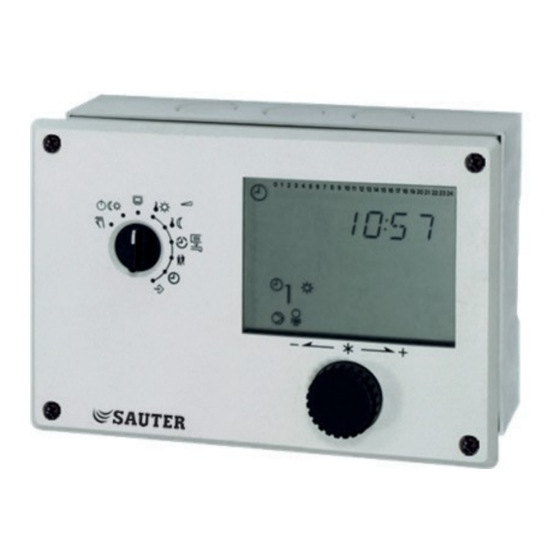
Контроллер системы управления отоплением — SAUTER EQJW 146 погодозависимый
Управление двумя контурами: отопление и/или система ГВС.
Функциональность погодозависимого контроллера SAUTER EQJW 146 позволяет нагревать питьевую воду и контролировать температуру теплоносителя по кривой нагрева или по 4-позиционной характеристике в зависимости от погодных условий.
Этот контроллер представлен в 29 различных моделях, подходящих для центрального отопления, одноконтурных бойлеров, нагрева воды с помощью солнечной энергии или промежуточного резервуара. Кроме того, он обладает удобными еженедельными и ежегодными программами переключения с оптимизацией времени переключения, а также автоматическим переходом на летнее/зимнее время.
Также возможно установить минимальное/максимальное ограничение температуры теплоносителя в подающем трубопроводе и максимальное ограничение температуры теплоносителя в обратном трубопроводе.
Контроллер имеет входы Ni/Pt1000 для внешнего и подающего контуров, обратного контура и температурного датчика помещения. Интерфейсы предусмотрены для подключения различных аксессуаров, таких как модем, шлюз, модуль регистрации данных и другие.
Кроме того, контроллер оснащен регистрационным журналом для мониторинга и записи данных.
Check and setting the times-of-use
Three times-of-use can be programmed for each day of the week. If only one time-of-use is required, the start and end times
of the second time-of-use must be identical. The third time-of-use is then no longer displayed. If two time-of-use periods are
required, the start and end times of the third time-of-use must be identical.
KA_EQJW146F001_EN011
Set rotary switch to times-of-use;
Time and parameter symbol flashing, heating (1) is displayed
In systems with only one control circuit (e.g. Anl 1.0), the steps for
selecting the control circuit and specifying the DHW circuit are not
required. In systems 1.5 and 1.9, only the DHW circuit is controlled, so the
steps for selecting the control circuit are omitted.
Turn the button;
Select the circuit:
Push the button;
Confirm the circuit
Turn the button;
Specify DHW:
Push button;
Confirm specification
Push button; Symbol for heating and daily digits are
displayed
Turn button; select day of week (1 = Monday,
2 = Tuesday, …, 1-7 = daily)
Times-of-use for weekdays are displayed for checking purposes
Press rotary pushbutton; start time for time-of-use is displayed.
Turn button; change start time for time-of-use
Press button; start time is confirmed
Stop time for times-of-uses is displayed
Turn button; Changing the stop time for the time-of-use
Push button; the stop time is confirmed; the times-of-use for the
following day of the week are displayed for checking purposes.
Turn button; ‘End’ is displayed
Push button
The time-of-use level for the control circuit is exited
Short Instruction Manual
Heating circuit 1
Heating circuit 2
DHW/Circulation pump
DHW
Circulation pump
7
| Источник питания | |
|---|---|
| Источник питания | 230 В перем. тока, ±15 %, 50– 60 Гц |
| Потребляемая мощность | Прибл. 1,5 В·А |
Параметры
| Регулировочная характеристика | Температура в подающем трубопроводе | PI-контроллер |
| Температура питьевой воды | Двухпозиционный | |
| Параметры управления | Усиление, KP | 0,1–50 |
| Время интегрального воздействия | 1–999 секунд | |
| Разница переключений для питьевой воды | 1–30 К | |
| Температурные диапазоны | Нормальная температура | от 0 до 40 °C |
| Сниженная температура | от 0 до 40 °C | |
| Температура в подающем трубопроводе | от 0 до 140 °C | |
| Температура обратного потока | от 0 до 140 °C | |
| Наружная температура | от −50 до 50 °C | |
| Температура питьевой воды | от 20 до 90 °C | |
| Температура защиты от замерзания | −15…3°C | |
| Время работы клапана | 30–300 секунд | |
| Время цикла | Время работы клапана ÷ 15 |
Условия окружающей среды
| Температура среды | от 0 до 40 °C |
| Влажность окружающего воздуха | 5–95 % отн. влажности, без конденсации |
| Температура хранения и транспортировки | от −10 до 60 °C |
Входы/выходы
| Количество выходов | 7 реле |
| Реле насоса | 3 × 2 A, 250 V~, cos φ > 0,5 |
| Реле привода | 4 × 2 A, 250 V~, cos φ > 0,5 |
| Непрерывный ввод-вывод | 1 × 0–10 В |
| Количество входов | 2 цифровых, 8 аналоговых |
| Аналоговые входы | 8 (Ni1000/Pt1000) |
Принцип работы
| Таймер | Резервный источник питания шины | Мин. 24 часа, стандартно 48 часов |
| Точность | < 10 минут/год | |
| Программа еженедельного переключения | Количество программ | 3 |
| Количество команд переключения | Каждые 42 | |
| Мин. интервал переключения | 15 минут | |
| Программа ежегодного переключения | Количество программ | 1 (для контуров отопления) |
| Количество команд переключения | каждые 20 | |
| Мин. интервал переключения | 1 день |
Интерфейсы и связь
| Связь | Интерфейс | RJ-45 |
| Протокол | Шина — Modbus (TAP) |
Конструкция
| Масса | 0,5 кг |
| Габариты | 144 × 98 × 54 мм |
| Корпус | Светло-серый |
| Материал корпуса | Огнестойкий термопластик |
| Монтаж | Стена, коммутационная панель, DIN-рейка |
| Винтовые клеммы | Для электрических кабелей сечением до 2,5 мм² |
Стандарты и директивы
| Тип защиты | IP40 (EN 60529) (при установке на панелях) | |
| Класс защиты | II (МЭК 60730-1) | |
| Класс программного обеспечения | A (МЭК 60730-1, Приложение H) | |
| Соответствие стандартам качества и безопасности Европейского союза (CE) согласно | Директива по электромагнитной совместимости 2014/30/EС | EN 61000-6-1, EN 61000-6-3 |
| Директива по низковольтному оборудованию 2014/35/EU | EN 60730-1 |
Обзор моделей
| Модель | Характеристики |
|---|---|
| EQJW146F001 | Тепловой контроллер и контроллер районного отопления с символьным дисплеем |
| EQJW146F002 | Тепловой контроллер и контроллер районного отопления с графическим дисплеем |
Принадлежности
| Модель | Описание |
|---|---|
| AVF*** | Моторизированный привод клапана (см. спецификации) |
| AVM*** | Моторизированный привод клапана (см. спецификации) |
| AXM*** | Моторизированный привод клапана (см. спецификации) |
| EGT*** | Датчик внешней температуры Ni1000 (см. спецификацию) |
| 0440210001 | Коммуникационный модуль для подключения контроллеров EQJW 126/146 к RS-232 (ПК) |
| 0440210002 | Коммуникационный модуль для подключения контроллеров EQJW 126/146 к модему |
| 0440210003 | Коммуникационный модуль для подключения контроллеров EQJW 126/146 к шине RS-485 |
| 0440210004 | Коммуникационный модуль для подключения контроллеров EQJW 126/146 к ведущей шине RS-485 |
| 0440210005 | Шлюз ModBus-TCP |
| 0440210011 | Шлюз ModBus-GPRS |
| 0440210006 | Шлюз ModBus-MBus |
| 0440210007 | Преобразователь/повторитель для интерфейсов RS-232 или RS-485 |
| 0440210008 | Защита от перенапряжений RS-485 |
| 0440210010 | Модуль хранения параметров для передающего контроллера |
| 0440210012 | Кабельный преобразователь для двухпроводникового интерфейса RS-485 |