- Manuals
- Brands
- SystemAir Manuals
- Air Conditioner
- SAVE VTC 300 R
Manuals and User Guides for SystemAir SAVE VTC 300 R. We have 2 SystemAir SAVE VTC 300 R manuals available for free PDF download: User Manual, Replacement Instructions Manual
SystemAir SAVE VTC 300 R User Manual (20 pages)
Brand: SystemAir
|
Category: Industrial Equipment
|
Size: 1.94 MB
Table of Contents
-
Table of Contents
3
-
Overview
5
-
General Description
5
-
Warranty
5
-
Type Label
5
-
Warnings
5
-
Operation
6
-
SAVE LIGHT Control Panel
6
-
Indicators
6
-
To Select Airflow Level
6
-
To Cancel Sleep Mode
7
-
To Change Control Panel Address (if more than One Control Panel Is Used)
7
-
SAVE TOUCH Control Panel / SAVE CONNECT
7
-
Common Symbols
8
-
Home Screen Overview
8
-
Status Bar and Alarms
8
-
Quick Information Screen
9
-
To Select User Mode
9
-
To Change the Temperature
11
-
To Change the Airflow
11
-
To Set a Week Schedule
12
-
Maintenance
13
-
Maintenance Schedule
13
-
To Access Internal Components
14
-
To Change Filters
14
-
To Reset the Filter Change Time
15
-
To Select a Different Filter Kit
15
-
To Clean the Heat Exchanger
15
-
To Clean Fans
16
-
System
17
-
Troubleshooting
17
-
Duct System Maintenance
17
-
Cleaning Extract Louvres and Supply Air Diffusers
17
-
Checking the Outdoor Air Intake
17
-
Checking the Roof Cowl (if Fitted)
17
-
Electrical Data
18
-
Disposal and Recycling
19
Advertisement
SystemAir SAVE VTC 300 R Replacement Instructions Manual (18 pages)
Changing the bypass damper
Brand: SystemAir
|
Category: Air Conditioner
|
Size: 7.23 MB
Table of Contents
-
Table of Contents
2
-
Warnings
3
-
Left and Right Models
3
-
Changing the Bypass Damper
4
-
Changing the Bypass Damper in the Units Produced before 10-08-2014
9
-
Disconnecting the Transformer
10
-
Mounting the New Bypass Damper and Connecting the Adapter
13
-
Advertisement
Related Products
-
SystemAir VRF series
-
SystemAir Villavent VX-400
-
SystemAir VX-700 E
-
SystemAir SAVE VTR 300/B
-
SystemAir SAVE VTR 250/B
-
SystemAir VTR 200
-
SystemAir VRF
-
SystemAir SAVE VTC 300
-
SystemAir SAVE VTC 700
-
SystemAir SAVE VTC 500
SystemAir Categories
Fan
Air Handlers
Ventilation Hood
![]()
Air Conditioner
Fire and Smoke Dampers
More SystemAir Manuals

SAVE VTC 300
Service & Accessories Installation Manual
GB
Document in original language | · v1.1
© Copyright Systemair UAB
All rights reserved
E&OE
Systemair UAB reserves the rights to change their products without notice.
This also applies to products already ordered, as long as it does not affect the previously agreed specifications.
Systemair is not liable or bound by the warranty if these instructions are not adhered to during installation or service.
| v1.1
Contents
1
2
3
4
5
Overview ......................................................1
1.1
Warranty ..............................................1
1.2
Type label.............................................1
1.3
Disposal and recycling .............................1
Important Safety Information .............................1
2.1
Intended Use.........................................2
2.2
Admonitions .........................................2
Configuration .................................................2
3.1
Startup wizard .......................................2
3.2
Common symbols...................................2
3.3
Home screen overview............................3
3.3.1
User modes ..............................3
3.3.2
Temperature settings ..................6
3.3.3
Airflow settings .........................6
3.3.4
Indoor Air Quality .......................7
3.3.5
Status bar and alarms..................7
3.4
Description of User functions ....................7
3.5
Main menu ...........................................8
3.5.1
Unit Information.........................8
3.5.2
Alarms .....................................9
3.5.3
Week Schedule ........................ 13
3.5.4
Filter ..................................... 14
3.5.5
System Preferences .................. 14
3.5.6
Service .................................. 14
3.5.7
Help ...................................... 23
Service ....................................................... 23
4.1
Warnings............................................ 23
4.2
Power consumption and fuse size ............ 23
4.3
Internal Components............................. 24
4.3.1
Description of
Components ........................... 24
4.4
Electrical Connections............................ 25
4.4.1
Main circuit board layout............ 25
4.4.2
External connections
(Connection board)................... 26
4.5
Troubleshooting ................................... 27
Accessories.................................................. 28
5.1
Internet Access Module (IAM) ................. 28
5.1.1
Setting up remote control of
the unit .................................. 29
5.2
Indoor air quality sensors ....................... 30
| v1.1
5.3
5.4
5.5
Temperature control ............................. 31
5.3.1
Electrical reheater .................... 31
5.3.2
Electric duct heater (control
via relay) ................................ 33
5.3.3
Duct water heater .................... 36
5.3.4
Duct water cooler..................... 37
5.3.5
Ground heat exchanger ............. 38
5.3.6
Change-over coil for heating/
cooling function ....................... 39
Airflow control..................................... 41
5.4.1
VAV/CAV conversion kit............. 41
Installation/Maintenance ....................... 42
5.5.1
Outdoor/Exhaust air
dampers................................. 42
5.5.2
Pressure Guard ........................ 43
5.5.3
Multiple control panels .............. 44
5.5.4
Presence detector .................... 46
5.5.5
Push button ............................ 46
Overview |
1
Overview
The key to proper and safe operating of the unit is to read this manual thoroughly, use the unit according to given
guidelines and follow all safety requirements.
1.1
Warranty
For the assertion of warranty claims, the products must be correctly connected and operated, and used in accordance
with the data sheets. Further prerequisites are a completed maintenance plan with no gaps and a commissioning report. Systemair will require these in the case of a warranty claim.
1.2
Type label
Before calling your service representative, make a note of the specification and production number from the type label,
which can be found on the side of the units, next to the external connections.
Fig. 1 Type label
Position
Description
1
Product code (product specification)
2
Product item number
3
Production order number
4
Serial number
5
Production date (YY.MM.DD)
6
Scannable code for manufacturing order (MO) number and software version
7
Scannable code for the spare parts list and documentation
1.3
Disposal and recycling
This product is compliant with the European WEEE Directive and related national waste
legislation. When disposing the unit, follow your local rules and regulations.
This product packing materials are recyclable and can be reused. Do not dispose in household
waste.
2
Important Safety Information
• Observe and respect local conditions, regulations and laws.
• Safety elements may not be dismantled, circumvented or deactivated.
• Wear protective equipment during all work in the vicinity of the unit.
| v1.1
1
2
| Configuration
• Do not allow children to play with the device.
2.1
Intended Use
• Abide by the system-related conditions and requirements of the system manufacturer or plant constructor.
• Keep all the warning signs on the device and in a legible condition.
• The device is not to be used by persons (including children) with reduced physical, sensory or mental capabilities, or
lack of experience and knowledge, unless they have been given supervision or instruction.
• The system should operate continuously, and only be stopped for maintenance/service.
• Do not connect tumble dryers to the ventilation system.
• Make sure that filters are mounted before starting the unit.
2.2
Admonitions
Danger
• Make sure that the mains supply to the unit is disconnected before performing any maintenance or
electrical work!
• All electrical connections and maintenance work must be carried out by an authorized installer and in
accordance with local rules and regulations.
Warning
• This product is not intended to be used by children or people with reduced physical or mental ability or
lack of experience and knowledge, if no instruction concerning the use has been given by the person
responsible for their safety or that this person is supervising the operation. Children should be supervised
so that they can not play with the product.
• Beware of sharp edges during mounting and maintenance. Use protective gloves.
Warning
• Risk of injury due to rotating parts that have not come to a complete standstill after mains supply to the
unit have been disconnected.
3
Configuration
SAVE VTC 300 configuration can be done via SAVE Touch control panel or alternatively via a mobile application.
Advanced settings cannot be performed using SAVE LIGHT control panel.
3.1
Startup wizard
During the first power up of the unit, you will be asked to set:
• menu language
• time and date
• import configuration file (if the Internet Access Module (IAM) with configuration file is available)
• airflow control type (Manual/RPM) and airflow level values
• heater type (None/Electrical/Water/Change-over)
• if necessary reset filter change timer
The Startup Wizard cannot be skipped.
Note:
If the SAVE LIGHT control panel is used, the start-up wizard is skipped and the factory settings are used.
3.2
Common symbols
The following selection symbols are common and are present in most menu pages:
| v1.1
Configuration |
On and Off slider to activate or
deactivate a function. White bubble —
function is inactive, green bubble —
function is active.
Back button to return to a previous
menu, located at the upper left corner
Up arrow to increase a value
CANCEL
Button to cancel changes
Down arrow to decrease a value
SET/OK
Buttons to confirm changes
Some menus have more than one page. Touch page indicator in the top right corner to go to the next page. The first
number indicates current page number and the second number indicates a total number of pages available.
Many options show up in a form of the pop-up window. Select the option from the displayed list in the pop-up window
and press OK to confirm selection.
3.3
Home screen overview
1. Menu
2. Active user mode
3. Temperature settings
4. Airflow settings
5. Alarms and warnings
6. Status line
7. Outdoor temperature
A. Return to home screen
E. Check and change remaining time till filter change
B. Basic read-only information about the unit
F. General system preferences
C. Currently active alarms and alarm history
G. Configuration of all system parameters
D. Configure and check week schedule
H. Help and troubleshooting menu
3.3.1
User modes
The first icon at the top of home screen shows currently active user mode. To change the user mode, touch the active
user mode icon (pos. 2) and select a new user mode from the list. The unit has 2 permanent and 5 temporary user
modes available for selection. Only one mode can be active at a time.
Settings of all modes can be modified in Service menu.
3.3.1.1 Permanent modes
Permanent modes are always active unless interrupted by temporary modes, activated user functions or alarms:
| v1.1
3
4
| Configuration
Icon
Text
Description
AUTO
Automatic airflow control. AUTO mode is available for selection when Demand
Control, Week Schedule and/or external fan control functions are configured,
otherwise AUTO mode icon won’t be visible in active user modes menu. AUTO
mode activates Demand Control, Week Schedule and/or external fan control
functions. Demand is available to choose as airflow setting in Week Schedule.
Manual selection of airflow levels. The unit can be set run at one out of four
available airflow speeds: Off/Low/Normal/High.
Note:
MANUAL
The fan can be set to OFF by activating Manual Fan Stop function in
Service menu.
3.3.1.2 Temporary modes
Temporary modes are active only for a set period of time unless interrupted by active user modes, activated user functions or alarms:
Icon
Text
Description
Holiday
Sets speed of both supply and extract air fans to Low levels when user is away
from home for a long period of time.
ECO mode is active.
Set duration in days.
Crowded
Sets speed of both supply and extract air fans to maximum High levels and
temperature setpoint offset to –3 K when apartment is more crowded than usual.
Default temperature setpoint offset is –3 K.
Set duration in hours.
Away
Sets speed of both supply and extract air fans to Low levels when user is away
from home for a short period of time.
ECO mode is active.
Set duration in hours.
Refresh
Sets speed of both supply and extract air fans to Maximum levels to replace
indoor air with a fresh air in a short period of time.
Set duration in minutes.
Fireplace
Sets speed of supply air fan to High level and extract air fan to Low level to
increase air pressure within the apartment for better smoke extraction through
the chimney.
Set duration in minutes.
Settings of all modes can be modified in Service menu.
Temporary modes and user functions are active only for a set period of time after which they are terminated and the
unit changes back to a former AUTO or MANUAL mode, depending on which one was active before temporary mode or
user function was activated.
Temporary modes can also be activated via digital input signal triggered by push button, presence detector, etc.
3.3.1.3 Digital input functions
Digital input functions always active while digital input is activated.
Icon
Text
Description
Central Vacuum
Cleaner
Function sets speed of supply air fan to High level and extract air fan to Low
level to increase air pressure within the apartment for better dust collection
through central vacuum cleaner.
Function can be activated via digital input — Central Vacuum Cleaner
Function.
Cooker hood
Sets speed of both supply and extract air fans to Maximum level to increase
airflow in the cooker hood.
Function can be activated via digital input — Cooker Hood Function.
| v1.1
Configuration |
Icon
Text
Description
Configurable
Digital Input 1
Configurable digital input for custom user function. Airflow levels for both fans
are freely configurable.
High–priority function.
Configurable
Digital Input 2
Configurable digital input for custom user function. Airflow levels for both fans
are freely configurable.
Mid–priority function.
Configurable
Digital Input 3
Configurable digital input for custom user function. Airflow levels for both fans
are freely configurable.
Low–priority function.
Pressure guard
Configurable digital input for pressure switch connection. Airflow levels for both
fans are freely configurable.
3.3.1.3.1Configurable digital inputs
A custom airflow settings for supply and extract fans can be set and assigned to a digital input. Each fan can have a different airflow setting.
Configurable digital input can be activated via signal triggered by push button, presence detector or any other external
device with digital output, such as Building Management Systems (BMS)
Configurable digital inputs are grouped in levels of priority, Configurable Digital Input 1 being the highest,
meaning it can’t be overwritten by other user functions.
3.3.1.4 Digital input and Mode hierarchy
User modes and functions have a different hierarchy. User functions activated via HMI or mobile APP, such as AWAY,
CROWDED, FIREPLACE, HOLIDAY and REFRESH, are interrupted by manual selection of AUTO and MANUAL fan modes.
A FIREPLACE function has the highest priority between user functions. Other functions activated via HMI/APP can interrupt each other.
If FIREPLACE function is hard-wired on the connection board and configured as digital input (DI) then it has a higher
priority than AUTO and MANUAL mode. Digital input for a FIREPLACE function has also a higher priority than other
hard-wired digital inputs (DI) for: AWAY, CENTRAL VACUUM CLEANER, COOKER HOOD, CROWDED, HOLIDAY or REFRESH.
Fig. 2 Hierarchy of user modes and digital inputs
Modes are listed from the highest to lowest priority; A — user modes that can be activated from the control panel; B —
user modes and functions activated via digital input
| v1.1
5
6
| Configuration
3.3.2
Temperature settings
Temperature can be set at SET TEMPERATURE menu accessible from the home screen by touching
TEMPERATURE icon with thermometer. Default temperature value is 18°C (range 12–30°C).
Use up and down arrows or a slider to change the value.
Then touch the OK button to confirm changes.
Temperature set point is for room air temperature, supply air temperature or for extract air temperature depending on
which control mode is active. Default setting is Supply air temperature control.
Control mode of the temperature can be changed in Service menu.
3.3.2.1 ECO mode
ECO mode is a power saving function that can be activated in SET TEMPERATURE menu.
ECO mode function is available only when an internal heater is installed and configured.
While ECO mode is active, a temperature setpoint at which heater is activated is lowered to avoid activation of the heater during cold nighttime.
If the temperature is very low and the heater is activated during the nighttime (even with lowered temperature setpoint), then during the upcoming daytime indoor temperature will be increased using the heat exchanger so that accumulated heat could be used during the next cold nighttime, the lowered setpoint for the heater remains.
ECO mode will have impact for the following user
functions/modes if selected:
ECO mode is always activated by the following modes:
• Auto
• Away
• Manual
• Holiday
• Away
• Holiday
ECO mode is always deactivated by the following user
functions/modes:
• Central Vacuum Cleaner Function
• Crowded
• Cooker Hood Function
• Refresh
• Fireplace
• Free cooling
3.3.3
Airflow settings
Airflow settings are available only in MANUAL mode. Click on fan icon on the main screen to enter SET
AIRFLOW menu.
| v1.1
Configuration |
Use up and down arrows or a slider to change the airflow value.
The airflow may be adjusted in these steps: Off/Low/Normal/High. These settings control output signals to the supply and extract fans.
Important
It is not recommended to set fan to Off in standard households. If manual fan stop is activated, the unit
should be provided with dampers in exhaust and fresh air ducts to avoid cold draught and risk of
condensation when the unit has been stopped.
The fan can be set to Off by activating Manual Fan Stop function in Service menu.
3.3.4
Indoor Air Quality
The unit automatically controls indoor humidity and/or CO2 levels by adjusting airflow setting. Airflow is
increased if air quality is decreasing.
Demand Control function is responsible for IAQ (Indoor Air Quality) regulation. Relative humidity (RH) and/or CO2 sensors are responsible for IAQ monitoring.
Indoor air quality (IAQ) indicator is available if AUTO mode and Demand Control function is activated.
Indoor air quality levels:
• Perfect: measured indoor air quality value is below setpoint.
• Good: measured indoor air quality value is between low and high limits.
• Improving: measured indoor air quality value is above high setpoint.
Different airflow settings can be set for IMPROVING and GOOD IAQ levels in Service menu.
Setpoint for relative humidity and CO2 level can be set in Service menu.
3.3.5
Status bar and alarms
Status line located at the bottom area of home screen displays information about:
List of active alarms. See
chapter 3.5.2.3 for more
information.
List of active user functions.
See chapter 3.4 for more
information.
Touching any of these lines will move you to the next page with more detailed list and information about each alarm or
active user function.
3.4
Description of User functions
Icon
Text
Heating
Heat recovery
Cooling
| v1.1
Description
Connected heater or pre-heater is active and air heating is in process.
Heat recovery from apartment is active.
Connected cooler is active and air cooling is in process.
7
8
| Configuration
Icon
3.5
3.5.1
Text
Description
Cooling recovery
Automatic cooling recovery is active when extract air temperature from
apartment is lower than outdoor air temperature and there is a cooling demand
(temperature setpoint is lower than outdoor air temperature).
No cooling recovery with heating demand. If the outdoor air temperature is
higher than then thee indoor air temperature and there is a heating demand,
function Free heating is activated instead.
Free cooling
Function decreases indoor air temperature by using only cool outdoor air during
nighttime to save energy consumption.
Moisture transfer
Function controls the rotation speed of the heat exchanger to prevent moisture
transfer to supply air due to high relative humidity in the extract air.
Function is only available for units with Rotating type heat exchanger.
Defrosting
Function prevents formation of the ice on the heat exchanger during cold
outdoor temperatures.
Secondary air
Warm air from the living space is used to defrost the heat exchanger using a
damper inside the outdoor air duct. The unit switches from outdoor air to
secondary air while the extract air fan stops and warm secondary air increases
the temperature inside the heat exchanger.
Vacuum cleaner
Function sets speed of supply air fan to High level and extract air fan to Low
level to increase air pressure within the apartment for better dust collection
through central vacuum cleaner.
Function can be activated via digital input — Central Vacuum Cleaner
Function.
Always active while digital input is activated.
Cooker hood
Sets speed of both supply and extract air fans to Maximum level to increase
airflow in the cooker hood.
Function can be activated via digital input — Cooker Hood Function.
User Lock
Function indicates that the system is locked with a password and cannot be
edited or settings changed in any way. System must be unlocked first to make
changes.
Configurable
Digital Input 1
Configurable digital input for custom user function. Airflow levels for both fans
are freely configurable.
High–priority function.
Configurable
Digital Input 2
Configurable digital input for custom user function. Airflow levels for both fans
are freely configurable.
Mid–priority function.
Configurable
Digital Input 3
Configurable digital input for custom user function. Airflow levels for both fans
are freely configurable.
Low–priority function.
Pressure guard
Configurable digital input for pressure guard connection. Airflow levels for both
fans are freely configurable.
Main menu
Unit Information
A basic read-only information about status of the unit, configured components and inputs/outputs.
3.5.1.1 Components
Type and settings of heat exchanger, heater, cooler, extra controller.
| v1.1
Configuration |
3.5.1.2 Sensors
Values from sensors and load of fans (rpm).
3.5.1.3 Input Status
Status of configured analog, digital and universal inputs. Connected component type and raw value (volts) is displayed.
3.5.1.4 Output Status
Status of configured analog, digital and universal outputs. Connected component type and value (volts) is displayed.
3.5.1.5 Unit Version
Unit model name, manufacturer number, serial number and unit software versions for Mainboard, HMI and IAM.
3.5.2
Alarms
A detailed information about active system alarms and alarm log of last 20 events.
3.5.2.1 Active Alarms
Alarm screen is empty if there are no active or logged alarms.
Press HELP button on the active alarm to access FAQ and troubleshooting (if available). Press ACKNOWLEDGE on the individual alarm to clear it. Depending on alarm type and the cause, it might be necessary to do a troubleshooting first to
acknowledge active alarm.
It may be not possible to clear the status of alarm if the cause of alarm is still present, as that would immediately trigger
alarm to return.
The control panel cannot go to sleep mode if at least one alarm is active.
3.5.2.2 Alarms log
Alarm log allows to view last 20 alarms.
Each alarm contains information:
• Alarm name
• Date/time stamp
• Information if the alarm stops the unit or other note
3.5.2.3 Alarm list
Alarm name
Explanation
Do the following
Frost protection of return water in
heating coil.
The alarm will reset once the water
temperature reaches 13°C.
Check the water fluid temperature in
heating coil.
Check the circulation pump of water
heater. Contact your installation
company or place of purchase.
A class alarms:
Frost protection
• Alarm stops the unit and opens
the water valve completely.
Frost protection temperature sensor
Indicates malfunction of water
heater temperature sensor.
• Alarm stops the unit.
| v1.1
Check that frost protection
temperature sensor is connected
properly and cable is not damaged.
Contact your installation company or
place of purchase.
9
10
| Configuration
Alarm name
Explanation
Do the following
Defrosting error
Indicates failure of pre-heater to
preheat the incoming outdoor air (in
case Extra controller is configured as
Preheater).
Check the pre-heater reset button.
Check the pre-heater cabling.
Contact your installation company or
place of purchase.
Defrosting error may be caused by
extremely low outdoor air
temperatures or pre-heater failure.
• Alarm stops the unit.
Supply air fan rpm
Rotation speed of the supply air fan
is lower than minimum required. Fan
malfunction.
Check quick connectors of the fan.
Contact your installation company or
place of purchase.
• Alarm stops the unit.
Extract air fan rpm
Rotation speed of the extract air fan
is lower than minimum required. Fan
malfunction.
Check quick connectors of the fan.
Contact your installation company or
place of purchase.
• Alarm stops the unit.
Supply air fan control error
Flow or pressure alarm for supply air.
The pressure is bellow pressure limit.
• Alarm stops the unit.
Extract air fan control error
Flow or pressure alarm for extract
air. The pressure is bellow pressure
limit.
• Alarm stops the unit.
Fire alarm
Fire alarm is active.
• Alarm stops the unit.
Low supply air temperature
Check that air tube for pressure
sensor is connected properly and
cable is not damaged.
Contact your installation company or
place of purchase.
Check that air tube for pressure
sensor is connected properly and
cable is not damaged.
Contact your installation company or
place of purchase.
Once the external Fire alarm is
disabled – alarm has to be
acknowledged and unit restarted.
Supply air temperature is too low.
Active: (Outdoor air temperature
sensor measures < 0°C) AND (Supply
air temperature sensor measures <
5°C)
Returned: (Supply air temperature
sensor measures > 10°C)
Check the heat exchanger and reheater.
Emergency thermostat
Indicates triggered overheat
protection (in case of installed
electric re-heater battery).
A triggered manual or automatic
overheat protection (EMT) gives an
alarm in the control panel.
In case a manual overheat protection
is triggered, reset it by pushing the
reset button.
If the automatic overheat protection
is triggered, it will reset
automatically once the temperature
has dropped.
If the problem continues contact
your installation company or place of
purchase.
Bypass damper feedback
Indicates malfunction in bypass
damper.
Disconnect the main power supply
for 10 seconds to reset the control
function.
Power up the unit, an automatic
bypass damper test will be
performed.
If the alarm occurs again after
approximately 3 minutes – contact
your installation company or place of
purchase.
B class alarms:
| v1.1
Configuration |
Alarm name
Explanation
Do the following
Rotor motor feedback
Indicates a rotor malfunction.
No feedback signal from the rotor
motor for 180 seconds.
If the rotating heat exchanger has
stopped, check the rotor belt.
Replace the belt if it is broken.
If the heat exchanger is still not
rotating check if the quick connector
of the rotary heat exchanger motor
is connected.
If the alarm persists, the motor may
be faulty. Contact your installation
company or place of purchase.
Rotor guard
Indicates a rotor malfunction.
No rotation guard signal for 180
seconds.
If the rotating heat exchanger has
stopped, check the rotor belt.
If the heat exchanger is still rotating,
check that the quick connector for
the sensor is connected and that
there is an air gap of 5-10 mm
between the sensor and the magnet.
Adjust the gap if necessary.
If the alarm persists, the rotor sensor
may be faulty. Contact your
installation company or place of
purchase.
Secondary air damper
Secondary air defrosting failed.
Outdoor air temperature sensor
measures < 10°C in 2 sec after
defrosting
OR
Outdoor air temperature sensor
measures < 5°C in 5 min after
defrosting
Check if secondary air damper is in
correct position.
Check that damper is connected
properly and cable is not damaged.
Contact your installation company or
place of purchase.
Outdoor air temperature sensor
Indicates outdoor air temperature
sensor malfunction.
Check that sensor is connected
properly and cable is not damaged.
Contact your installation company or
place of purchase.
Heater Overheat
Indicates overheat temperature
sensor malfunction.
Check that sensor is connected
properly and cable is not damaged.
Contact your installation company or
place of purchase.
Supply air temperature sensor
Indicates supply air temperature
sensor malfunction.
Check that sensor is connected
properly and cable is not damaged.
Contact your installation company or
place of purchase.
Room air temperature sensor
Indicates room air temperature
sensor malfunction.
Check that sensor is connected
properly and cable is not damaged.
Contact your installation company or
place of purchase.
Extract air temperature sensor
Indicates extract air temperature
sensor malfunction.
Check that sensor is connected
properly and cable is not damaged.
Contact your installation company or
place of purchase.
Extra controller temperature sensor
Indicates extra controller
temperature sensor malfunction.
Check that sensor is connected
properly and cable is not damaged.
Contact your installation company or
place of purchase.
Built-in RH sensor
Indicates internal relative humidity
sensor malfunction.
Active: measured humidity = 0%
Returned: measured humidity > 5%
Check that sensor is connected
properly and cable is not damaged.
Contact your installation company or
place of purchase.
| v1.1
11
12
| Configuration
Alarm name
Explanation
Do the following
Built-in extract air temperature
sensor
Indicates internal extract air
temperature sensor malfunction.
Active: measured temperature = 0°C
Returned: measured temperature >
5°C
Check that sensor is connected
properly and cable is not damaged.
Contact your installation company or
place of purchase.
Extra controller alarm
Error from external device.
Check if external device is connected
properly and cable is not damaged.
Reset overheat protection on
electrical pre-heater. Contact your
installation company or place of
purchase.
Filter warning
Notification about filter change.
Filter have to be replaced in one
month time. Please acquire new
filters.
Filter
Time for filter change.
Change the filter.
Change filter according to the
instructions in the User Manual.
Details about filter retailers can be
found in Help menu.
External stop
Unit is stopped by external signal.
Operation is stopped by digital signal
from external remote device or
signal from building management
system.
Manual Fan Stop
Operation stopped, fans are in
manual mode and selected as OFF.
Select another speed of fans (LOW /
NORMAL / HIGH) or AUTO mode in
HMI home screen.
Overheat Alarm
Temperature after reheater is too
high.
Active: (Overheat temperature
sensor measures > 55°C)
Returned: (Overheat temperature
sensor measures < 50°C)
Alarm is possible if supply airflow is
too low when the reheater is
switched on.
Check the supply airflow.
Check that intake grille is not
blocked.
Check that shut off damper for
outdoor air is open in operation.
Contact your installation company or
place of purchase.
External CO2 sensor
External CO2 sensor malfunction.
Check that sensor is connected
properly and cable is not damaged.
In case sensor wireless – check
RS485 gateway status and sensor
status in HMI.
Contact your installation company or
place of purchase.
External RH sensor
External relative humidity sensor
malfunction.
Check that sensor is connected
properly and cable is not damaged.
In case sensor wireless – check
RS485 gateway status and sensor
status in HMI.
Contact your installation company or
place of purchase.
Output in manual mode
One or more of analog outputs are in
manual mode.
Check Service->Output menu.
Make sure all configured outputs are
set to Auto value.
C class alarms:
Alarm Fire Alarm can be only activated with a digital signal from a smoke/fire detection system or similar. Digital input has to be configured as Fire Alarm for this alarm to work.
Digital output configured as Sum Alarm sends a generic signal every time the alarm is triggered, except for alarms External stop, Output in manual mode and Manual Fan Stop. This signal does not specify the alarm type.
| v1.1
Configuration |
3.5.3
Week Schedule
The unit can be configured to operate at set airflow levels up to two time periods (00:00–23:59) on user
selected days.
Week Schedule is active only during AUTO mode.
It is possible to activate or deactivate digital output for schedule and unscheduled periods.
3.5.3.1 Schedule Airflow Settings
Touch settings icon to go to SCHEDULE AIRFLOW SETTINGS menu. In this menu set airflow level for
scheduled and unscheduled periods. Available levels: Off, Minimum, Low, Normal, High, Maximum or
Demand.
Set temperature setpoint offset for both periods (-10°C – 0°C).
Demand level is available only if Demand Control or External fan function is active.
3.5.3.2 Edit Schedule
While in home screen, touch menu icon and select Week Schedule.
The menu is locked by default. Enter a password (default password is 1111).
Touch icon at the bottom left corner of the screen to add a new schedule or press EDIT button to modify already added
schedule.
Week Schedule is active only during AUTO mode.
Touch the slider to the right to activate scheduled period.
| v1.1
13
14
| Configuration
Set the time. Touch the START TIME or END TIME values to change time. Use arrow buttons
decrease value. Confirm with OK button.
and
to increase or
Note:
Scheduled time can start but never end at midnight (00:00). The latest END TIME period is 23:59. Scheduled
time cannot go to the next day.
12 or 24 hour time format can be changed in System Preferences menu.
If necessary, activate second scheduled period and set up time.
Once time is set, click on the day(s) when schedule should be active. It is possible to set a separate schedule for each
day. Already scheduled days are not available for selection for new schedules.
Confirm schedule with OK button.
3.5.4
Filter
In this menu the remaining time until filter change and filter kit for replacement are displayed. Editing is
locked with a password, use administrator password. See Password Settings in Service menu for
more information.
Set the time until the next filter change (3–15 months). The default setting is 8 months.
A filter change notification is shown one month prior to filter change.
If a new filter period is selected and confirmed or filter alarm is acknowledged, the timer resets and starts counting from
the beginning.
To change filter kit type
1. Touch Select different filter kit button in the alarm menu.
Alternatively, go to Filter menu (3.3 Home screen overview, page 3, pos. E).
2. Select filter kit from the list.
3. Touch OK button.
To reset filter change timer for SAVE LIGHT
• Push and hold
3.5.5
and
buttons for 3 seconds to reset the filter timer (filter change LED will turn off).
System Preferences
Configuration of unit location, language and time.
Change the following information:
• Language (default language is English)
• Country (default country is UK)
• Unit address (address, post code)
• Unit date and time, activate or deactivate summer/winter time switch.
Time will automatically change between summertime and wintertime according to European standard, based on
Greenwich time zone and set unit location.
Switch between 12 and 24 hours time format.
• Contact information: contractor, installer, service, phone, website, e-mail, etc.
• Display settings: screen brightness and screen behavior in standby mode.
3.5.6
Service
All unit parameters and settings can be changed in the Service menu.
The Service menu is locked by default and it is necessary to enter a password (default
password is 1111).
| v1.1
Configuration |
3.5.6.1 Input
Configuration of inputs
Settings for analog, digital and universal input terminals on the main board and connection board, configuration of
functionality.
Table 1 Digital universal inputs available for selection
User Modes
Activation of specific user modes.
Central Vacuum Cleaner
Function
Activation of Central vacuum cleaner function.
Cooker Hood Function
Activation of Cooker Hood function.
External Stop
Air handling unit is stopped by an external command.
Extra controller alarm
Indication about an alarm in external controller. Used for Extra Heater/Cooler/
Preheater.
Change-over feedback
Used with Change-over systems. Indicate if the temperature of heating/cooling fluid
in the system is right.
Fire alarm
Air handling unit is stopped due to fire. Can be used with smoke alarms or similar.
Configurable Digital Input 1
Activation of custom airflows set by user.
Configurable Digital Input 2
Activation of custom airflows set by user.
Configurable Digital Input 3
Activation of custom airflows set by user.
Pressure guard
Digital input from a pressure guard component
Relative humidity and rotation speed signals from fans are already pre-addressed to specific terminals and cannot be
changed, all other inputs are free for configuration by commissioning. Inputs are free to be used for any purpose.
Universal input (UI) configured as universal analog input (UAI) can be configured for several inputs because multiple
sensors of the same type can be used. Universal analog inputs (UAI) have only selections for RH Sensor (RH), CO₂
Sensor (CO₂), Supply Air Fan Control (SAFC) and Extract Air Fan Control (EAFC) wired configurations.
Analog input (AI) temperature sensors are not allowed to be configured more than once.
Same user modes can be configured on multiple digital inputs (for example multiple bathrooms can be connected to different digital inputs with Refresh mode configured for each.
Digital inputs can be configured to be normally open (Normally Open (NO)) or normally closed (Normally Closed
(NC)). Default setting is Normally Open (NO). Not available for wireless inputs.
A time delay for user modes activated via digital input can be switched off or enabled. Time delay indicates how long
the user mode remains active after its duration of operation has expired.
PDM (pulse density modulation) input for relative humidity (RH) sensor on the main board is pre-adressed and cannot
be changed.
Table 2 Overview of input configuration
Analog inputs
Digital inputs
Universal analog inputs
Universal digital inputs
Input type
Value
Compensation
Input type
Polarity
Value
Input type
Analog type
Value
Input type
Digital type
Polarity
Value
3.5.6.2 Output
Configuration of outputs.
Settings for analog, digital and universal output terminals on the main board and connection board, configuration of
functionality.
| v1.1
15
16
| Configuration
Table 3 Digital outputs available for selection
Step Controller Y1 Heating
Step Controller Y3 Cooling
Step Controller Y4 Extra
Controller
Heater/Cooler/Extra controller control signals.
Sum Alarm
Fault indicating output.
Outdoor-/Exhaust Air
Damper
Outdoor-/Exhaust air damper control signal.
Secondary air
Secondary air damper control.
Activate Cooling
Cooling mode activation signal to an external system.
Interlock External fan control
Automatic indication about prohibited external fan control (i.e. if defrosting is
activated).
Start/Stop Circ. Pump, Y1
Heating
Start/Stop Circ. Pump, Y3
Cooling
Start/Stop Circ. Pump,Y1/3
Change-over
Start/Stop Circ. Pump, Y4
Extra Controller
Start/Stop signal to the circulation pump of the Heating/Cooling/Extra controller.
Week schedule Unscheduled
Digital output signal activated during unscheduled week period.
Week schedule - Scheduled
Digital output signal activated during scheduled week period.
Unit Status OK
Digital output signal is activated if there are no active or unacknowledged alarms.
Fan output PWM (Pulse-width modulation) signal and triac output are already pre-addressed to specific terminals and
cannot be changed, all other outputs are free for configuration by commissioning. Outputs are free to be used for any
purpose.
Digital outputs are restricted by signal type and physical number of connections.
An output function is only allowed to be used once. Already used and configured terminal is greyed-out in the menu for
output type selection.
Analog and digital outputs have a selection for Auto/Manual modes and an adjustable value for Manual mode.
Manual mode selection overwrites all system related automatic functions. Analog output adjustable manual value
range is 0–10V and digital output values On/Off.
Table 4 Overview of output configuration
Analog outputs
Digital outputs
Output type
Auto/Manual
Value
Output type
Auto/Manual
Value
3.5.6.3 Components
Configuration of connected components.
Heat Exchanger
• Choose heat exchanger type.
• Activate or deactivate passive house function if heat exchanger type Rotating is selected.
Options: Yes / No.
• Choose bypass damper location if heat exchanger type Plate is selected. Default setting is based on unit type.
Supply / Extract
• Set actuator type. Default setting is based on unit type.
| v1.1
Configuration |
Range: 0–10 V / 2–10 V / 10–0 V / 10–2 V.
Heater
• Choose heater type. Each selection unlocks additional configuration options. Default setting is based on unit type.
Available types: None / Electrical / Water / Change-over.
• Set actuator type. Default value is 0–10 V.
Range: 0–10 V / 2–10 V / 10–0 V / 10–2 V.
• Set circulation pump temperature. Default setting is 10°C. This option is available if Water / Change-over heater
type is selected.
Range: 0–20°C.
• Set circulation pump stop delay. Default setting is 5 minutes. This option is available if Water / Change-over heater type is selected.
Range: Off / 1–60 min.
Cooler
• Choose cooler type. Each selection unlocks additional configuration options. Default setting is None.
Available types: None / Water / Change-over.
• Set outdoor air temperature interlock. Default setting is 10°C.
Range: 0–20°C.
• Set actuator type. Default value is 0–10 V
Range: 0–10 V / 2–10 V / 10–0 V / 10–2 V.
• Set circulation pump stop delay. Default setting is 5 minutes. This option is available if Water / Change-over heater type is selected.
Range: Off / 1–60 min.
Extra Controller
• Choose extra controller type. Each selection unlocks additional configuration options. Default setting is None.
Available types: None / Preheater / Heating / Cooling / GEO Exchanger.
• Set temperature set point of the extra controller. Default value is 0°C.
Range: –30°C — 40°C.
• Set P-band. Default setting is 4°C.
Range: 1-60°C.
• Set I-time. Default setting is Off.
Range: Off / 1–240 sec.
• Set actuator type. Default value is 0–10 V.
Range: 0–10 V / 2–10 V / 10–0 V / 10–2 V.
• Set circulation pump temperature. Default setting is 0°C. This option is available if Preheater controller type is
selected.
Range: 0–20°C.
• Set circulation pump stop delay. Default setting is 5 minutes.
Range: Off / 1–60 min.
Bellow menus are available if controller type is selected as GEO Exchanger.
• Pre-heater settings:
Set-point (-30 °C to + 10 °C).
Activation temperature (-30 °C to 0 °C).
• Pre-cooler settings:
Set-point (10 °C to 30 °C).
Activation temperature (15 °C to 30 °C).
| v1.1
17
18
| Configuration
3.5.6.4 Control Regulation
Configure how the system is controlled.
Temperature Control
• Configure temperature controller. Choose control mode:
Available modes: Supply air temperature control / Room temperature control / Extract air temperature control
Note:
Room temperature control mode requires an accessory to measure room temperature.
• Choose temperature unit. Default setting is Celsius.
Available units: Celsius / Fahrenheit
• Set P-band. Default setting is 20°C. Set I-time. Default setting is 100 sec.
• Configure SATC Split for cooler (0–20%), heat exchanger (25–60%) and heater (65–100%) output settings.
Range: 0–100%.
• Configure cascade control setpoint for min/max supply air temperature, P-band, I-time.
Only available for Room temperature control / Extract air temperature control modes.
ECO Mode
• Configure ECO mode settings. Set heater offset. Default setting is 5°C.
Range: 0–10°C.
Fan Control
• Configure airflow and fan settings. Select fan control (airflow) type. Default setting is Manual (%).
Available types: Manual (%) / Manual rpm / Flow (CAV) / Pressure (VAV) / External
Setting
Manual
RPM
Pressure
(VAV)
Flow (CAV)
External
Airflow
measurement
unit.
%
rpm
l/s, m3/h, cfm
P-Band
–
0–3000 rpm
0–500 Pa
–
I-Time
-
Off / 1–240 sec.
Default setting: 5
sec.
Off / 1–240 sec.
Default setting: 5 sec.
–
Airflow level
settings for each
level: MAXIMUM
LEVEL, HIGH
LEVEL, NORMAL
LEVEL, LOW
LEVEL,
MINIMUM LEVEL
16-100%
500–5000 rpm
Sensor range (airflow unit)
0–100%
Pa
%
Manual Fan Stop — turn on or off manual fan stop, this function enables manual fan stop from HMI. Default setting
is OFF.
| v1.1
Configuration |
Setting
Manual
RPM
Pressure
(VAV)
Flow (CAV)
External
Pressure
Sensors —
configure sensor
voltage relation
to pressure.
Set value at
which fan alarm
occurs. Default
setting is None
-
-
Supply air fan control sensor:
Pressure at 0V: 0-500 Pa, default
setting 0 Pa
Pressure at 10V: 0-2500 Pa, default
setting 500 Pa.
Extract air fan control sensor:
Pressure at 0V: 0-500 Pa, default
setting 0 Pa.
Pressure at 10V: 0-2500 Pa, default
setting 500 Pa
Set K factor for
supply air fan
and extract air
fan. Default
settings are
based on unit
type.
-
-
SAF K-Factor
range: 0–1000
EAF K-Factor
range: 0–1000
Outdoor
Compensation
A purpose of this function is to protect the unit from freezing by creating an unbalanced airflow
at extreme winter temperatures or to limit supply of cold/hot outdoor air at extreme winter/
summer conditions with balanced ventilation.
Function operates by lowering the speed of supply air fan (SAF) or both supply and extract air
fans (SAF/EAFC) by value set in Stop Compensation Value setting (adjustable from 0% to
50%) if the outdoor air temperature (OAT) drops below adjustable value set in Start
Compensation Temperature setting (during winter from 0 °C to -30 °C / during summer
from 15 °C to 30 °C). This compensation reaches the maximum as soon as the outdoor air
temperature reaches the adjustable value set in Stop Compensation Temperature setting
(during winter from 0 °C to -30 °C / during summer from 15 °C to 30 °C)
-
-
-
Important
Changing the airflow type does not change P-band value automatically. P-band value have to be changed
manually after changing the airflow type.
Demand Control
Configure indoor air quality sensors. Once sensor(s) are configured, Demand Control function is activated by choosing
AUTO mode in home screen.
• Activate or deactivate CO2 sensor. Default setting is Off.
Set CO2 sensor setpoint. Default setting is 800 ppm (parts per million in atmosphere). Normal atmospheric CO2 concentration is 400 ppm. Range: 100–2000 ppm.
Set P-band, default setting is 200 ppm. Range: 50–2000 ppm.
Set I-Time, default setting is Off. Range: Off/1–120 sec.
• Activate or deactivate RH sensor. Default setting is Off.
Set humidity setpoint in summer, default setting is 60%. Range: 1–100%.
Set humidity setpoint in winter, default settting is 50%. Range: 1–100%.
Set P-band, default setting is 10%. Range: 1–100%.
Set I-time, default setting is Off, Range: Off/1–120 sec.
• Select airflow level for Improving Air Quality. Range: Normal / High / Maximum.
• Select airflow level for Good Air Quality. Range: Low / Normal.
Moisture Transfer Control
Note:
Setting is available if heat exchanger type is set as Rotating. It is highly recommended to leave default
values for P-band and I-time. They should be changed only by installer and trained staff.
• Activate or deactivate relative humidity transfer functionality. Default setting is On.
• If Moisture Transfer Control is activated, configure:
| v1.1
19
20
| Configuration
Setpoint, default setting is 45% humidity. Range: 1–100% RH.
Set P-band, default setting is 4g/kg. Range: 1–100g/kg.
Set I-time, default setting is Off. Range: Off/1–120 sec.
Defrosting Control
Note:
Setting is available if heat exchanger type is set as Plate.
The unit is equipped with an automatic defrost function that is activated when there is risk of icing in the area around
the heat exchanger.
• Select defrosting mode. Default setting is Normal.
1
Soft
Dry areas, such as warehouse buildings with few people or industrial
buildings that don’t use water in their production process.
Normal
Apartments or houses with normal humidity 1
Hard
Buildings with very high humidity level.
In newly constructed houses it might be necessary with a higher defrost level during the first winter period.
• Set by-pass location. Default setting is based on unit configuration.
Supply / Extract.
• Set if secondary air is allowed. Default setting is Off.
Off / On.
Cooling Control
• If the outdoor air is warmer than the extract air and the supply air is above the setpoint, cooling recovery occurs. This
condition blocks the heat regulation process. Activate or deactivate cooling recovery. Default setting is On.
Set cooling limit. Cooling recovery is allowed if extract air temperature is lower than outdoor air temperature by a set
limit (default setting is 2K) and cooling demand is present.
• Configure status, temperature and duration of free cooling. Activate or deactivate free cooling . Default setting is
Off.
Set supply and extract air fan levels during free cooling. Default setting is Normal. Range: Normal / High /
Maximum.
Set start/stop conditions. Extract/Room air temperature, default setting is 18°C. Outdoor high temperature limit, default setting is 23°C. Outdoor low temperature limit is 12°C. Start and stop time.
3.5.6.4.1Finding RPM for desired airflow
It is necessary to set fan RPM (revolutions per minute) for each airflow level to control airflow by changing fan speed.
Fan speed differ for each household because of different unit size, duct system and system pressure. In order to find
correct fan speed, external tool must be used at Systemair website.
1. Go to Systemair website and find your unit.
2. Go to Diagram tab and type in desired airflow values in l/s, m3/h, m3/s or cfm for supply and extract air. Input pressure drop in duct system (if this value is not know, type in 100 Pa for both supply and extract air)
Fig. 3 Example of airflow and external pressure selection
3. See calculated speed values in revolutions per minute (rpm) for both supply and extract air in the table bellow
diagrams.
| v1.1
Configuration |
Fig. 4 Example speed for supply and extract air
4. Use this procedure to find fan speed for all airflow levels: MINIMUM LEVEL, LOW LEVEL, NORMAL LEVEL, HIGH LEVEL, MAXIMUM LEVEL.
5. Finally in the control panel go to Service menu, enter the password, then go to Control Regulation → Fan
Control. Choose RPM as airflow type and in sub-menu Airflow Level Settings enter calculated fan speed values for each level.
3.5.6.5 User Modes
Set airflow level, duration and offset for each user mode.
Set supply and extract air fan levels, default duration and temperature offset where available for user modes:
• Away
• Central Vacuum Cleaner
• Cooker Hood
• Crowded
• Fireplace
• Holiday
• Refresh
• Configurable Digital Input 1
• Configurable Digital Input 2
• Configurable Digital Input 3
• Pressure guard
3.5.6.6 Communication
Configure Modbus and wireless settings
Modbus
• Set Modbus address. Default setting is 1.
• Set baud rate. Default setting is 115200.
• Set parity. Default setting is None. Range: None / Even / Odd.
• Set stop bits. Fixed value: 1.
• Shows Smartly-Gateway state.
HMI Address
• When more than one control panel is connected to the unit, it is important that each control panel would have a different address number. This menu displays current HMI address.
For more information see 5.5.3 Multiple control panels, page 44.
WLAN Settings
WLAN settings are for connection of the Internet access module (IAM) accessory.
Internet access module (IAM) is a device that allows to connect to the unit and control it via a mobile application or directly from the computer.
• Shows current connection status.
• Shows network name to which the internet access module is connected.
• Scan for networks — use this search function to find your local protected network. Detailed procedure is described bellow.
| v1.1
21
22
| Configuration
Connecting the IAM to wireless network
1. If your wireless router does not support WPS, Wi-Fi connection should be set up manually. Therefore you need to
find Wi-Fi name and add password using control panel.
2. In control panel go to Service -> Communication -> WLAN settings menu.
3. Press Scan for networks button. IAM will search for available Wi-Fi networks (should not take longer than one
minute).
4. After search is complete, find the network name to which IAM should connect and select it. Wi-Fi network should
be password protected, otherwise IAM can't connect to Wi-Fi network.
5. After required Wi-Fi name selection, password pop-up window appears in control panel screen. Insert your Wi-Fi
network password.
6. If password is correct and connection to Wi-Fi network is successful, IAM will establish connection to server automatically. The LED of IAM will start blinking slowly in green colour.
• Reset WLAN settings when needed.
3.5.6.7 Logs
Information about alarms, fans and parameters are stored in Logs menu.
Fans Levels
• Time counter for each supply air fan level duration is displayed. Counted and total time. Reset counted time.
Level 1: 0–20%
Level 2: 21–40%
Level 3: 41–60%
Level 4: 61–80%
Level 5: 81–100%
Parameters
• Select parameter type, position in y-axis, period from 60 minutes to 2 weeks and then create a graph based on
stored data by touching icon in the top right corner
available in mobile application)
. Export parameters data by touching arrow button
. (only
3.5.6.8 Unit Backups
Menu for restoring factory settings or importing/exporting configuration file from/to the Internet Access
module (IAM).
• Touch Factory settings menu to restore factory configuration and parameters. This will also overwrite changed
password. You will be asked to confirm the task before proceeding.
Note:
This selection will automatically restart the unit. The Startup Wizard have to be re-done after restart.
• Touch Save current configuration to IAM option to save your current system configuration file to the connected Internet Access Module.
• Touch Download current configuration from IAM to download configuration file from the connected Internet
Access Module.
•
Touch Set User Safe Configuration option to store current settings in the unit memory as a backup. It can later
be used as a fail-safe configuration copy in addition to factory settings.
• Touch Activate User Safe Configuration option to restore the backup copy of system settings from the unit
memory.
3.5.6.9 Password Settings
Service level is always locked with a password. Other menu levels have a separate option for locking. If password requirement is activated for different menu levels, these are unlocked with the administrator password.
Choose what menus should be locked or not.
| v1.1
Service |
3.5.7
Help
FAQ, troubleshooting of alarms, contact information for support is provided in this menu.
• Service partner — information about service partner.
• Company
• Telephone
• Homepage
• Email
• User modes— detailed description of all user modes.
• Functions— detailed description of different user functions.
• Alarms— detailed description of all alarms.
• Troubleshooting— information about all different possible malfunctions.
4
Service
4.1
Warnings
Danger
• Make sure that the mains supply to the unit is disconnected before performing any maintenance or
electrical work!
• All electrical connections and maintenance work must be carried out by an authorized installer and in
accordance with local rules and regulations.
Warning
• This product must only be operated by a person who has suitable knowledge or training within this field
or carried out with the supervision of a suitably qualified person.
• Beware of sharp edges during mounting and maintenance. Use protective gloves.
Warning
• Although the mains supply to the unit has been disconnected there is still a risk of injury due to rotating
parts that have not come to a complete standstill.
Important
• The installation of the unit and complete ventilation system must be performed by an authorized installer
and in accordance with local rules and regulations.
• The system should operate continuously, and only be stopped for maintenance/service.
• Do not connect tumble dryers to the ventilation system.
• Duct connections/duct ends must be covered during storage and installation.
• Make sure that filters are mounted before starting the unit.
4.2
Power consumption and fuse size
Table 5 Power Consumption
Model
Fans (W )
Heater (W)
Total (W)
Fuse (mains) (A)
VTC 300
170
–
170
10
VTC 300 with reheater
170
1700
1870
10
| v1.1
23
24
| Service
4.3
Internal Components
Fig. 5 Components
Position
1
Description
1
Fan, supply air
2
Fan, extract air
3
Filter, outdoor air
4
Filter, extract air
5
Defrost damper 1
6
Heat exchanger
7
Condensation tray
8
Condensation drain
9
Connection box
10
Print card with terminals
11
Temperature sensor, supply air
12
Temperature sensor, outdoor air
13
Relative humidity/Temperature sensor, extract air
14
Fast couplings for supply- and extract air fan
The damper may not be turned by hand!
4.3.1
Description of Components
4.3.1.1 Fans
Fans have an external EC type rotor which can be steplessly controlled individually 16–100%. The motor bearings are
life time lubricated and maintenance free. It is possible to remove the fans for cleaning, see “User Manual” for more
information.
| v1.1
Service |
4.3.1.2 Filters
The air filter captures dust, mold, pollen and other particulate matter.
The filters need to be replaced when polluted. New sets of filters can be acquired from your installer or wholesaler.
4.3.1.3 Defrost damper
The built in bypass damper (pos. 5 figure 5) is involved in defrosting, cool recovery, and supply air temperature control
of the unit. The damper motor is controlled by an analogue 0–10 V signal.
A test sequence which opens and closes the damper will occur if there is heating demand and after every power up of
the unit. An actuator drive detects if the bypass is able to close completely. If a signal is not detected within two minutes after the function test has been initiated, then the warning Bypass Damper appears in the HMI.
4.3.1.4 Heat exchanger
SAVE VTC 300 is equipped with a counter flow heat exchanger. Required supply air temperature is therefore normally
maintained without adding additional heat.
4.3.1.5 Main circuit board
The main circuit board controls all functions and the unit.
It is possible to connect external accessories to a free terminals on the main circuit board.
4.3.1.6 Temperature sensors
Three temperature sensors (NTC, 10 kΩ) are included in the unit from factory:
The sensors are wired to the main print card. See wiring diagram for more information.
4.3.1.7 Humidity sensor
Relative humidity sensor (RHS/EAT) is positioned in the extract air chamber and connected to the main circuit board.
See wiring diagram for more information.
4.4
Electrical Connections
The SAVE VTC 300 is wired internally from factory. The electrical connection box can be found in the supply air fan compartment. The top cover plate is removed by removing 2 screws in the lower front edge of the cover plate (figure 6).
All external connections to possible accessories are made to terminals on the connection board (chapter 4.4.2).
Fig. 6 Opening the electrical connection box
4.4.1
Main circuit board layout
The SAVE VTC 300 is equipped with built-in regulation and internal wiring.
| v1.1
25
26
| Service
Fig. 7 Main circuit board connections
Position
Description
CB
Connection to the external connection box
1
Terminals for a heater
2
Terminals for a TRIAC
3
Terminals for the mains power supply
4
Terminals for power supply of extract air fan
5
Terminals for power supply of supply air fan
6
Terminals for internal relative humidity/temperature sensor
7
Analog input 1 — Outdoor air sensor
8
Analog input 2 — Supply air sensor
9
Analog input 3 — Freely configurable
10
Analog input 4 — Freely configurable / Overheat temperature sensor (units with
heater)
11
Analog input 5 — Freely configurable
12
Digital input 1 — Rotor guard sensor (only for VSR, VTR models)
13
Digital input 2 — Freely configurable / Cooker hood (VTR 150/K unit)
14
Analog output 2 — Freely configurable / Electrical heater controller (VTC 700 unit)
15
Analog output 1 — Rotary heat exchanger control signal (for VSR, VTR type models) /
Damper control signal (for VTC, VSC type models), UI6 — Bypass damper feedback
signal (for VTC, VSC type models)
16
Terminals for speed control of extract air fan
17
Terminals for speed control of supply air fan
4.4.2
External connections (Connection board)
External connections to the main circuit board are done via connection board situated inside of the unit.
| v1.1
Service |
Fig. 8 External connection box and board
Position
Description
1
Connection to the main circuit board
2
Connection for external control panel (HMI) or Internet access module (IAM)
3
Modbus RS485 connection
AI6–7
Freely configurable Analog input. None/Input type selection in HMI.
DO1–4
Freely configurable digital output.
DO2 default configuration: Outdoor-/Exhaust Air Damper
DO3 default configuration: Activate Cooling
DO4 default configuration: Sum Alarm
AO3–5
Freely configurable analog output. Actuator type 0–10V, 10–0V, 2–10V, 10–2V.
AO3 default configuration: Heating (only for VTC 200/300/500/700, VTR 100/700 type models).
AO4 default configuration: Cooling
UI1–5
Freely configurable universal input. Can be set as analog input (0–10 V) or a digital input (24 V).
UI1 default configuration: Pressure guard
UI2 default configuration: Cooker hood
UI3 default configuration: Fire alarm
UI4 default configuration: Refresh
24V
Maximum current 200mA at 24VDC +-10%.
4.5
Troubleshooting
If problems should occur, please check the items below before calling your service representative.
Fans do not start
1. Check the control panel for alarms.
2. Check that all fuses and fast couplings are connected (main power supply and fast couplings for supply and extract
air fans).
3. Check the week schedule. Fans may be set to OFF in the Schedule airflow settings menu.
Reduced airflow
1. Check the control panel for alarms. Some alarms can reduce the airflow to LOW if active.
2. The unit could be in defrost mode. This reduces the fan speed and in some cases shuts down the supply air fan completely during the defrosting cycle. The fans go back to normal after defrosting. There should be a defrosting function
icon visible on the home screen if defrosting is active.
3. Speed of fans is linearly reduced when the outdoor air temperature is below 0°C and an outdoor airflow compensation function is enabled.
4. Check if temporary user mode that reduces airflow is not activated, for example Away, Holiday, etc. Also check digital inputs Central Vacuum Cleaner and Cooker Hood.
| v1.1
27
28
| Accessories
5. Check the airflow settings in the control panel.
6. Check week schedule settings (chapter 3.5.3).
7. Check filters. Is change of filters required?
8. Check diffusers/louvres. Is cleaning of diffusers/louvres required?
9. Check fans and heat exchange block. Is cleaning required?
10.Check if the buildings air intake and roof unit (exhaust) have been clogged.
11.Check visible duct runs for damage and/or build up of dust/pollution.
12.Check diffuser/louvre openings.
The unit cannot be controlled (control functions are stuck
1. Reset control functions by disconnecting mains power for at least 10 seconds.
2. Check the modular contact connection between the control panel and the main printed circuit board.
Low supply air temperature
1. Check the control panel for alarms.
2. Check the active user functions on the control panel if defrosting function is running.
3. Check set supply air temperature on the control panel.
4. Check if ECO mode is activated on the control panel (it is a power saving function and prevents the heater from
activating).
5. Check if user modes Holiday, Away or Crowded are activated on the control panel or via a hardwired switch.
6. Check the analogue inputs in the service menu to verify that the temperature sensors are functioning correctly.
7. In case of installed electrical/other re-heater battery: Check if the overheat protection thermostat is still active. If
necessary, reset by pressing the red button on the front plate of the electrical re-heater.
8. Check if the extract filter must be changed.
9. Check if the unit has a re-heater battery connected. At very cold outdoor conditions an electrical or water heating
battery might be necessary. A re-heater battery can be acquired as an accessory.
Noise/vibrations
1. Clean fan impellers.
2. Check that the screws holding the fans are tightened.
3. Check that the anti vibration lists are fitted to the mounting bracket and to the back of the unit.
5
Accessories
SAVE VTC 300 have many available accessories that can be used to expand functionality of the unit and increase comfort level.
Recommended accessories can be always found at Systemair website www.systemair.com by searching the article
number or the name of the desired accessory.
5.1
Internet Access Module (IAM)
Internet access module is a device that allows to connect to the unit and control it via a mobile application or directly from the computer and receive automatic updates.
SAVE Touch Cloud
The Cloud is a mediator between the user and the unit. To access your unit
via Cloud, it has to be connected to the internet via Internet Access Module.
Component/product — Article number:
• IAM – 323606
| v1.1
Accessories |
5.1.1
| v1.1
Setting up remote control of the unit
29
30
| Accessories
Note:
The internet access module uses TCP port 8989. Make sure it is not blocked.
Description
A. Connect the Internet Access Module (IAM) to the Connection Board (CB) with included RJ10 cable.
B. Power up the IAM with included power supply cable and adapter (230 V~).
C. Enable access to the internet. Three options are available:
• C1 — Activate WPS function on your router (if available) and press the button on the Internet Access Module for 5
seconds.
• C2 — Plug one end of the Ethernet cable to the RJ45 socket on IAM and the other end to any free Ethernet socket
on your router. The connection will be established automatically.
• C3 — Set up connection to your Wi-Fi through Communication menu in control panel.
D. Access Systemair mobile application. Two options are available:
• D1 — Download and install Systemair mobile application on your device. Systemair mobile application is available
for both Android and iOS mobile operating systems.
• D2 — Systemair web application does not require installation and can be accessed directly through the website
(homesolutions.systemair.com ) by using any web browser.
E. Launch the application. In the login screen enter your unique UNIT ID which can be found on the back label of IAM or
on additional label.
Press LOG IN button.
It is required to create a unique password when connecting to IAM for the first time. Touch Change password button. In the next menu screen enter your new password, confirm it and touch SET PASSWORD button. To finalize password creation, click the button on the IAM. Wait for a message to pop up in your app telling that password was
changed.
Touch BACK button to return to the previous login screen. Enter the newly created password and touch LOG IN
button.
For more information read the manual that comes with the accessory.
Table 6 LED indicator codes
WLAN
Connected
Disconnected
Connected
—
—
—
Ethernet
—
—
—
Connected
Disconnected
Connected
Cloud
Not Connected
Disconnected
Connected
Not Connected
Disconnected
Connected
RED LED
Blinks fast
Blinks slow
—
—
—
—
GREEN LED
—
—
Blinks slow
Blinks fast
Blinks fast
Blinks slow
Fast blinking — every 500 milliseconds. Slow blinking — every 2 seconds.
5.2
Indoor air quality sensors
Indoor air quality sensors (IAQ) are CO2, relative humidity and temperature
transmitters that must be installed either in extract air duct or the room depending on the type of transmitter.
| v1.1
Accessories |
• IAQ — indoor air quality sensor (CO2, RH and
temperature)
• CO2 — CO2 duct sensor
• 1 — Outdoor air
• 2 — Supply air
• 3 — Extract air
• 4 — Exhaust air
Component/product — Article number:
• Systemair-1 CO2 duct sensor — 14906
• Systemair-E CO2 sensor — 14904
• Room sensor 0-50C (temperature) — 211525
• Systemair-E CO2 RH Temperature — 211522
Installation and connection
1. Install IAQ sensor in the duct or the room depending on
the transmitter type.
2. Connect CO2 sensor to any free universal analog input
(UI) on the connection board.
3. If IAQ sensor contains relative humidity transmitter:
Connect it to any free universal analog input (UI) on the
connection board.
4. If IAQ sensor contains room temperature transmitter:
Connect it to any free analog input (AI) on the connection board (only AI6 and AI7 are available on the connection board).
Fig. 9 IAQ connections
Configuration
1. Go to Service menu.
2. Enter password (default 1111).
3. Configure of CO2 and/or relative humidity sensor: Go to Input menu. Select UNIVERSAL tab. Select the universal input to which the sensor is connected. Example if it is connected to UI4 on the connection board, then select UNIVERSAL INPUT 4. Select signal type as Analog input and select sensor type from the input type list: RH sensor (RH)
and/or CO₂ Sensor (CO₂).
4. Configure room temperature sensor: Go to Input menu. Select ANALOG tab. Select the analog input to which the
sensor is connected. Example if it is connected to AI6 on the connection board, then select ANALOG INPUT 6. Select
input type as Room Air Temperature Sensor (RAT).
5.3
5.3.1
Temperature control
Electrical reheater
Electrical reheater is used for supply air heating during cold outside temperatures. Electrical
reheater should be installed inside of the unit.
| v1.1
31
32
| Accessories
• ELH — Electrical heater
• OHT — overheat protection sensor
• 1 — Outdoor air
• 2 — Supply air
• 3 — Extract air
• 4 — Exhaust air
Component/product — Article number:
• Reheater VTC 300 R (for right version model) — 138107
• Reheater VTC 300 L (for left version model) — 139312
Installation and connection
1 Remove the cover of reheater by loosening screws at the front (pos. 1).
| v1.1
Accessories |
2 Remove knobs in the reheater compartment (pos. 1),
they will be used to hold the reheater in place.
Remove the main circuit board cover plate by removing 2 screws (pos. 2) in the lower front edge of the
plate.
3 Insert reheater, lead cables trough holes on the side
(pos. 1).
Secure reheater in place using previously removed
knobs (pos. 2).
• Connect reheater control wires to the terminal
block marked as HEATER (pos. 4) on the main circuit board. Connect blue wire to N socket, brown
wire to L socket.
• Connect TRIAC wires to the terminal block marked
as TRIAC (pos. 5) on the main circuit board. Connect
black wire to G socket, brown wire to A1 socket,
gray wire to A2 socket.
• Connect overheat protection sensor to any free
analog input on the main circuit board (pos. 6).
Connect black wire to ground (GND), red fire to
analog input.
4 Place back covers of reheater and the main circuit
board and secure them with screws.
Note:
For more detailed information see a wiring diagram delivered with the unit.
Configuration
1. Go to Service menu
2. Enter password (default 1111)
3. Go to Components menu, select Heater menu and select type as Electrical. Do advanced settings if necessary.
4. Configure overheat protection sensor. Go back to Input menu. Select ANALOG tab. Select the analog input to which
the overheat protection sensor is connected. Example if it is connected to AI4 on the main circuit board, then select
ANALOG INPUT 4 and select Overheat Temperature Sensor (OHT) from the input type list.
5. Configure TRIAC. Go to Output menu. Select ANALOG tab then select TRIAC OUTPUT and set output type as Y1
Heating.
5.3.2
Electric duct heater (control via relay)
The electric heater can be installed in outdoor or supply air ducts.
| v1.1
33
34
| Accessories
• ELH — electric heater
ECT
230 V~
• ECT — extra controller temperature sensor
• OAT — outdoor air duct temperature sensor
• SAT — supply air temperature sensor
ELH
230 V~
AI
SAT
RL
ELH
AI
RL
3
• RL — relay
• 1 — Outdoor air
2
1
ELH
AI
4
DO
DO
ECT
SAT
• 2 — Supply air
• 3 — Extract air
• 4 — Exhaust air
Component/product — Article number:
• CB 160-2,7 230V/1 Duct heater — 5382
• CB Preheater Connection Kit — 142852
5.3.2.1 Heater installed in the outdoor air duct
Installation and connection
1. Install an electric heater (ELH) at least 100 mm distance
from the unit in the outdoor air duct. A relay (RL) is
used to control the heater. Connect relay to any free
digital output on the connection board (CB).
2. Connect the power supply to the electric heater via a
relay. A circuit breaker (BRK) is not included in the
package and must be ordered separately. It must be installed in the circuit.
3. Install a duct temperature sensor (OAT) before the
electric heater and connect it to any free analog input
on the connection board (CB).
Outdoor air heater configuration
1. Go to Service menu
2. Enter password (default 1111)
3. Set the heater type: Components —> Extra Controller —>Extra Controller Mode —> Preheater.
4. Configure connection of the pre-heater. Go to Service menu. Select Output menu. In next menu select DIGITAL
tab. Select the digital output to which the pre-heater is connected. Example if it is connected to DO3 on the connection board, then select DIGITAL OUTPUT 3 and select Step Controller Y4 Extra Controller from the output
type list.
5. Re-configure an internal outdoor air temperature sensor as the extra controller temperature sensor: Service —>
Input —> ANALOG tab. Select the ANALOG INPUT 1 and change its configuration from Outdoor Air Temp. Sensor (OAT) to Extra Controller Temp. Sensor (ECT).
6. After sensor configuration is changed, select the analog input to which the installed outdoor air temperature sensor
(OAT) is connected (for example AI5) and configure it as Outdoor Air Temp. Sensor (OAT).
| v1.1
Accessories |
5.3.2.2 Heater installed in the supply air duct
Installation and connection
1. Install an electric heater (ELH) at least 100 mm distance
from the unit in the supply air duct. A relay (RL) is used
to control the heater. Connect relay to any free digital
output on the connection board (CB).
2. Connect the power supply to the electric heater via a
relay. A circuit breaker (BRK) is not included in the
package and must be ordered separately. It must be installed in the circuit.
3. Install a duct temperature sensor (SAT) after the electric heater and connect it to any free analog input on
the connection board (CB).
Supply air heater configuration
1. Go to Service menu
2. Enter password (default 1111)
3. Set the heater type: Components > Heater > Electrical.
4. Configure connection of the heater. Go to Service menu. Select Output menu. In next menu select DIGITAL tab.
Select the digital output to which the heater is connected. Example if it is connected to DO3 on the connection board,
then select DIGITAL OUTPUT 3 and select Step Controller Y1 Heating from the output type list.
5. Deactivate the internal supply air sensor: Service > Input > ANALOG > ANALOG INPUT 2 > Supply Air Temp.
Sensor (SAT) > Inactive Input.
6. After sensor configuration is changed, select the analog input to which the installed supply air temperature sensor
(SAT) is connected (for example AI5) and configure it as Supply Air Temp. Sensor (SAT).
5.3.2.3 Heater installed in the supply air duct (extra zone)
Installation and connection
1. Install an electric heater (ELH) at least 100 mm distance
from the unit in the supply air duct. A relay (RL) is used
to control the heater. Connect relay to any free digital
output on the connection board (CB).
2. Connect the power supply to the electric heater via a
relay. A circuit breaker (BRK) is not included in the
package and must be ordered separately. It must be installed in the circuit.
3. Install a temperature sensor (ECT) after the electric
heater and connect it to any free analog input on the
connection board (CB).
Supply air heater configuration
1. Go to Service menu
2. Enter password (default 1111)
3. Set the heater type: Components > Extra Controller > Extra Controller Mode > Heating.
4. Configure connection of the heater. Go to Service menu. Select Output menu. In next menu select DIGITAL tab.
Select the digital output to which the heater is connected. Example if it is connected to DO3 on the connection board,
then select DIGITAL OUTPUT 3 and select Step Controller Y4 Extra Controller from the output type list.
5. Configure the installed sensor. Go to menu Service > Input > ANALOG. Select the analog input to which the sensor
is connected. Example if it is connected to AI6 on the connection board, then select ANALOG INPUT 6 > Extra Controller Temp. Sensor (ECT).
| v1.1
35
36
| Accessories
5.3.3
Duct water heater
A duct water heating battery is supposed to be installed in supply air duct.
• WH — water heating battery
• FPT — frost protection sensor
• SAT — supply air temperature sensor
• S — actuator for valve
• 1 — Outdoor air
• 2 — Supply air
• 3 — Extract air
• 4 — Exhaust air
Component/product — Article number:
• VBC 160-2 Water heating battery (2 rows) — 5458
• VBC 160-3 Water heating battery (3 rows) — 9840
• VAZ4 24A Actuator 0-10V (S) — 9862
• ZTV 15-0,4 2-way valve — 9829
• ZTV 15-0,6 2-way valve — 6571
• ZTR 15-0,4 valve 3-way — 9670
• ZTR 15-0,6 valve 3-way — 6573
• Duct sensor -30-70C (SAT) — 211524
• Surface sensor -30-150C (FPT) — 211523
• Transformer 24V — 202692
Installation and connection
1. Install water heater in the duct. Connect pipes, 2/3–
way valve and actuator.
Important
Do NOT use 24V DC power output from the
connection board for valve actuator.
2. Connect actuator (S) to any free analog output.
Fig. 10 Water heater connections
3. The frost protection sensor (FPT) should be strapped on a surface on the return water pipe. Connect FPT sensor to
any free analog input.
4. An internal supply air temperature sensor (SAT, default connection AI2 on the main circuit board) must be replaced
by a duct temperature sensor which can be acquired as an accessory. A duct temperature sensor must be installed in
the duct after water heater. Connect the duct temperature sensor to analog input 2 (AI2) replacing the internal supply
air temperature sensor.
Note:
A duct temperature sensor can be connected to analog inputs 6–7 on the connection board for better
access and then configured as a supply air temperature sensor. However the internal supply air
temperature sensor must be disabled in the control panel first.
Configuration
1. Go to Service menu
2. Enter password (default 1111)
3. Activate the actuator. Go to Components menu, select Heater menu and select type as Water. Choose actuator
voltage type. Do advanced settings if necessary.
| v1.1
Accessories |
4. Configure control signal to the actuator. Go to Service menu. Select Output menu. In next menu select ANALOG
tab. Select the analog output to which the control wire of the actuator is connected. Example if it is connected to AO3
on the connection board, then select ANALOG OUTPUT 3 and select Y1 Heating from the output type list.
5. Configure frost protection sensor (FPT). Go back to Input menu. Select ANALOG tab. Select the analog input to which
the frost protection sensor is connected. Example if it is connected to AI6 on the connection board, then select ANALOG INPUT 6 and select Frost Protection Temperature Sensor (FPT) from the input type list.
6. Since a duct temperature sensor replaces internal supply air temperature sensor, it doesn’t need to be re-configured.
Note:
A duct temperature sensor can be connected to analog inputs 6–7 on the connection board for better
access and then configured as a supply air temperature sensor. However the internal supply air
temperature sensor must be disabled in the control panel first.
7. Water heater and its components are now configured.
5.3.4
Duct water cooler
A duct water cooler is supposed to be installed in supply air duct to provide a
cooled down air to the apartment.
• WC — water cooling battery
• SAT — supply air temperature sensor
• S — valve actuator
• 1 — Outdoor air
• 2 — Supply air
• 3 — Extract air
• 4 — Exhaust air
Component/product — Article number:
• CWK 160-3-2,5 Duct cooler,circ — 30022
• RVAZ4 24A Actuator 0-10V (S) — 9862
• ZTV 15-0,4 2-way valve — 9829
• ZTV 15-0,6 2-way valve — 6571
• ZTR 15-0,4 valve 3-way — 9670
• ZTR 15-0,6 valve 3-way — 6573
• Duct sensor -30-70C (SAT) — 211524
• Transformer 24V — 202692
Installation and connection
1. Install a duct water cooler in the duct. Connect pipes, 2/
3–way valve and actuator.
Important
Do NOT use 24V DC power output from the
connection board for valve actuator.
Fig. 11 Duct cooler connections
2. Connect actuator (S) to any free analog output.
3. An internal supply air temperature sensor (SAT, default connection AI2 on the main circuit board) must be replaced
by a duct temperature sensor which can be acquired as an accessory. A duct temperature sensor must be installed in
the duct after water cooler. Connect the duct temperature sensor to analog input 2 (AI2) replacing the internal supply
air temperature sensor.
| v1.1
37
38
| Accessories
Note:
A duct temperature sensor can be connected to analog inputs 6–7 on the connection board for better
access and then configured as a supply air temperature sensor. However the internal supply air
temperature sensor must be disabled in the control panel first.
Configuration
1. Go to Service menu
2. Enter password (default 1111)
3. Activate the actuator. Go to Components menu, select Cooler menu and select type as Water. Choose actuator
voltage type. Do advanced settings if necessary.
4. Configure control signal to the actuator. Go to Service menu. Select Output menu. In next menu select ANALOG
tab. Select the analog output to which the control wire of the actuator is connected. Example if it is connected to AO3
on the connection board, then select ANALOG OUTPUT 3 and select Y3 Cooling from the output type list.
5. Since a duct temperature sensor replaces internal supply air temperature sensor, it doesn’t need to be re-configured.
Note:
A duct temperature sensor can be connected to analog inputs 6–7 on the connection board for better
access and then configured as a supply air temperature sensor. However the internal supply air
temperature sensor must be disabled in the control panel first.
6. Duct cooler and its components are now configured.
5.3.5
Ground heat exchanger
The ground heat exchanger can be connected to an outdoor air duct to heat the air and prevent the heat exchanger
from icing up, or to cool the air to reduce the need for cooling.
• GHT — Ground heat exchanger
• ECT — extra controller temperature sensor
• OAT — outdoor air duct temperature sensor
• RL — relay
• 1 — Outdoor air
• 2 — Supply air
• 3 — Extract air
• 4 — Exhaust air
| v1.1
Accessories |
Installation and connection
1. Install the ground heat exchanger (GE) at least 100 mm
distance from the unit in the outdoor air duct. Relay
(RL) is used to control the ground heat exchanger. Connect the relay to any free digital output on the connection board (CB).
2. Connect the ground heat exchanger (GE) and the
power supply to the relay (RL). A circuit breaker (BRK)
is not included in the package and must be ordered
separately. It must be installed in the circuit.
3. Install a duct temperature sensor (OAT) before the
ground heat exchanger in the outdoor air duct and connect it to any free analog input on the connection board
(CB).
Configuration
1. Go to Service menu.
2. Enter password (default 1111)
3. Go to Components > Extra Controller > Extra Controller Mode menu and select GEO Exchanger option.
If necessary change settings in the menus Configure preheater settings and Configure precooler
settings.
4. Configure control signal. Go to Service > Output > DIGITAL menu. Select the digital output to which the ground
heat exchanger is connected. Example if it is connected to DO3 on the connection board, then select DIGITAL OUTPUT 3 and select Start/Stop Circ. Pump, Y4 Extra Controller from the output type list.
5. Configure internal outdoor temperature sensor as extra controller temperature sensor. Go to Service > Input >
ANALOG > ANALOG INPUT 1 and change input configuration from Outdoor Air Temp. Sensor (OAT) to Extra
Controller Temp. Sensor (ECT).
6. After sensor configuration is changed, select analog input to which the newly installed duct temperature sensor
(OAT) is connected and configure input as Outdoor Air Temp. Sensor (OAT).
5.3.6
Change-over coil for heating/cooling function
Change-over coil can be used for both heating and cooling based on the demand.
Important
The change-over (heating/cooling) system can be implemented in many different ways and may vary in
each household. This description explains the most common solution for connecting and controlling heating
and cooling with a water coil and a heat pump.
| v1.1
39
40
| Accessories
• WH/WC — change-over coil
• FPT — frost protection sensor (optional)
• SAT — supply air temperature sensor
• THS — thermostat for sensing if the temperature of
heating/cooling fluid in the system is right (optional)
• HP — heat pump (or other device for heating and
cooling)
• CWP — water pump
• RL — relay
• 1 — Outdoor air
• 2 — Supply air
• 3 — Extract air
• 4 — Exhaust air
Component/product — Article number:
• Duct sensor -30-70C (SAT) — 211524
• Surface sensor -30-150C (FPT) — 211523
• PSS48 Transformer 24V — 204385
• Relay 24V with socket — 159484
Installation and connection
1. Install change–over coil in the duct. Install a water pump if necessary. The turning on and off of water pump should
be controlled with a relay (RL). Connect the relay to any free digital output and 24 V on the connection board. Then
connect the power supply and a water pump (CWP) to the relay.
2. Connect a control signal wire (if available) of the heat pump (HP) to any free digital output and 24 V on the connection board.
3. Connect cooling and heating start signal wires to any free digital outputs on the connection box. Relays (RL) must be
used.
4. The frost protection sensor (FPT) should be strapped on a surface on the return water pipe. Connect the frost protection sensor (FPT) sensor to any free analog input.
5. An internal supply air temperature sensor (SAT, default connection AI2 on the main circuit board) must be replaced
by a duct temperature sensor which can be acquired as an accessory. A duct temperature sensor must be installed in
the duct after heater/cooler. Connect the duct temperature sensor to analog input 2 (AI2) replacing the internal supply air temperature sensor.
Note:
A duct temperature sensor can be connected to analog inputs 6–7 on the connection board for better
access and then configured as a supply air temperature sensor. However the internal supply air
temperature sensor must be disabled in the control panel first.
6. A thermostat can be used to send signals (change-over feedback) regarding which actual medium (hot or cold) is
currently in a pipe. This signal can be also sent directly from the heat pump if such function is available. If heating is
demanded but only cold water/refrigerant is available - heating is deactivated).
Connect a change-over feedback wire (THS) to any free digital input and 24 V on the connection board.
Fig. 12 Change-over heating/cooling connections
| v1.1
Accessories |
Configuration
Before change-over heating/cooling can be activated, all components must be configured in the control panel.
1. Go to Service menu
2. Enter password (default 1111)
3. Go to Components menu, select Heater menu and select type as Change-over. Do advanced settings if
necessary.
Go to Components menu, select Cooler menu and select type as Change-over. Do advanced settings if
necessary.
4. Configure control signal of the heat pump or similar device. Go to Service menu. Select Output menu. In next
menu select ANALOG tab. Select the analog output to which the control signal wire is connected. Example if it is connected to AO3 on the connection board, then select ANALOG OUTPUT 3 and select Y1 / Y3 Change-over from the
output type list.
5. Configure heating start signal. Go to Output. Select DIGITAL tab. Select the digital output to which the heating start
signal wire from the heat pump is connected. Example if it is connected to DO1 on the connection board, then select
DIGITAL OUTPUT 1 and select Step Controller Y1 Heating from the output type list.
6. Configure cooling start signal. Go to Output. Select DIGITAL tab. Select the digital output to which the cooling start
signal wire from the heat pump is connected. Example if it is connected to DO2 on the connection board, then select
DIGITAL OUTPUT 2 and select Step Controller Y3 Cooling from the output type list.
7. Configure frost protection sensor (FPT). Go back to Input menu. Select ANALOG tab. Select the analog input to which
the frost protection sensor is connected. Example if it is connected to AI6 on the connection board, then select ANALOG INPUT 6 and select Frost Protection Temperature Sensor (FPT) from the input type list.
8. Configure temperature feedback signal from the pipe or heat pump. Go to Input menu. Select UNIVERSAL tab. Select the universal input to which the feedback wire is connected. Example if it is connected to UI1 on the connection
board, then select UNIVERSAL INPUT 1. Set signal type as Digital input and select an option Change-over
feedback from the input type list.
9. Since a duct temperature sensor replaces internal supply air temperature sensor, it doesn’t need to be re-configured.
Note:
A duct temperature sensor can be connected to analog inputs 6–7 on the connection board for better
access and then configured as a supply air temperature sensor. However the internal supply air
temperature sensor must be disabled in the control panel first.
10.Configure relay for water pump control. Go to Output. Select DIGITAL tab. Select the digital output to which the
relay is connected. Example if it is connected to DO3 on the connection board, then select DIGITAL OUTPUT 3 and
select Start/Stop Circulation Pump, Y1/Y3 Change-over from the output type list.
5.4
5.4.1
Airflow control
VAV/CAV conversion kit
The VAV/CAV conversion kit is used for VAV/CAV control of residential units.
Note:
The accessory package contains all needed parts for VAV conversion, however for use with CAV, an IRIS
damper or a similar device with known K factor has to be purchased.
Component/product — Article number:
• VAV/CAV conversion kit — 140777
• SPI-160 C Iris damper — 6753
Installation and connection
• Follow instructions in the manual which is delivered with the accessory.
| v1.1
41
42
| Accessories
5.5
5.5.1
Installation/Maintenance
Outdoor/Exhaust air dampers
If manual fan stop is activated, the unit should be provided with dampers in exhaust and outdoor ducts
to avoid cold draught and risk of condensation when the unit has been stopped.
• RL — relay box
• U- outdoor air damper
• V — exhaust air damper
• 1 — Outdoor air
• 2 — Supply air
• 3 — Extract air
• 4 — Exhaust air
Component/product — Article number:
• EFD 160 Damper + TF230 motor (U/V) — 7122
• TUNE-R-160-3-M4 (U/V) — 311969
• Relay kit:
RMK — 153549
• Relay kit with a transformer for 24 VAC dampers:
RMK–T — 153548
For all possible connection variations please see wiring diagram delivered with the relay mounting kit.
| v1.1
Accessories |
Note:
24 VAC dampers can be powered and
controlled only by using a relay mounting kit
with a transformer (article number: 153548).
This installation procedure describes how to connect
dampers powered by 230 V~ with a relay mounting kit
without transformer (article number: 153549).
Installation and connection
1. Install dampers (U/V).
2. Connect control signal wires (24V, DO) coming out from
the relay box (RL) to any free digital output on the connection board (CB).
3. Connect power supply wires (N) from dampers to the
terminal block. Connect control signal wires (Y, line)
from dampers to relay socket terminals (11, 21). See
illustration.
When damper with a non-spring return actuator is
used, an addition power line (L) has to be connected to
the terminal block since such damper requires constant
power supply.
4. Connect power supply wires (L, N) coming out from the
relay box to 230 V~ power source.
Fig. 13 Damper connection
Configuration
1. Go to Service menu
2. Enter password (default 1111)
3. Configure control signal to the relay. Go to Output menu. Select DIGITAL tab. Select the digital output to which the
relay is connected. Example if it is connected to DO3 on the connection board, then select DIGITAL OUTPUT 3 and
select signal type as Outdoor-/Exhaust Air Damper from the output type list.
5.5.2
Pressure Guard
A differential pressure switch is used to detect air pressure difference in a duct. The contact in the switch changes (on/
off) when air pressure exceeds the setpoint value.
One of the possibilities is to use this device with a cooker hood which has an internal fan. Turned on cooker hood causes
air pressure to increase in the exhaust air duct. After exceeding a set air pressure value in the pressure switch, wires
from the ventilation unit get connected by contact and signal is sent to the ventilation unit to activate the Pressure
Guard function.
| v1.1
43
44
| Accessories
1. A differential pressure switch
2. Metal tube
3. Exhaust air direction
4. Exhaust air duct
1. Mount a differential pressure switch in a suitable place,
for example on or near the outlet duct from the kitchen
fan.
Set the pressure switch to the lowest possible pressure,
for example 20 Pa.
2. There are two possible installation cases. A pressure
switch tube is installed in the duct:
a. after the fan – connect plastic tube to P1 positive
pressure connection on the relay, P2 negative pressure connection shall be left open.
b. before the fan – connect plastic tube to P2 negative
pressure connection on the relay, P1 positive pressure connection shall be left open.
Install a rubber bush in the duct. Insert the S-shaped copper pipe into the rubber bushing so that it points towards the
air flow (i.e. towards the outlet opening for the fan).
3. Use strips to lock the rubber tube and the pipe in the correct position.
4. Connect a 2–wire cable from the connection box (UI, 24V) to the pressure
switch terminals (NO and COM).
5. Connect pressure switch wires to one of the 5 universal inputs, marked
“UI1–5” and “24V” on the connection board. “UI1” and “24V” are pre-configured for this function, see wiring diagram of the ventilation unit.
COM
UI
CB
NC
NO
24 V
Please contact your installer to find air pressure for your system. It may necessary to perform several tests and calibrations to find pressure, increased by
the cooker hood, at which the differential pressure switch gets activated.
Note:
The exhaust air pressure and air pressure increase caused by the cooker hood is different for each
ventilation system.
Set the switch activation pressure value using the knob under the lid. The setpoint value is visible through
the lid.
Configuration
1. Go to Service menu
2. Enter password (default 1111)
3. Go to Input menu. Select UNIVERSAL tab.
4. Select the universal input to which wire from the differential pressure switch is connected.
Example if it is connected to UI1 on the connection board, then select option UNIVERSAL INPUT 1. Set signal type as
Digital Input and select an option Pressure Guard from the input type list.
5.5.3
Multiple control panels
Multiple control panels (up to 10) can be connected to one unit with the help of diverting plugs. A single diverting plug
allows to connect two control panels. A diverting plug can be connected to another diverting plug to further increase
the number of control panels that can be connected simultaneously.
| v1.1
Accessories |
Note:
• If the 24 V power supply on the connection board (CB) is used for other equipment, the number of control
panels that can be powered from the unit will decrease.
• A single active control panel draws 50 mA. The connection board supplies up to 250 mA. If no other
accessories use 24 V power supply from the unit, up to 5 control panels can be connected without a need
of external power supply. In order to connect more than 5 control panels, an external power supply is
required.
Control panel is available in black or white colour.
• DP — diverting plug
• HMI — control panel
Component/product — Article number:
• CE/CD-diverting plug 4pin — 37367
• CEC Cable w/plug 12m — 24782
• CEC Cable w/plug 6m — 24783
• SAVE TOUCH White — 138077
• SAVE TOUCH Black — 138078
• SAVE LIGHT White — 319118
• SAVE LIGHT Black — 319119
Installation and connection
1. Connect diverting plug to the connection box socket dedicated for external control panel (HMI) or Internet access
module (IAM).
2. Plug in control panels to diverting plug(s) using recommended cables or any cable with RJ22 type plugs.
Note:
The maximum supported cable length is 50 meters.
Configuration
1. Go to Service menu
2. Enter password (default 1111)
3. Go to Communication ⇒ HMI Address and change the address number. Repeat these steps for each connected
control panel.
Each control panel must have it’s own unique address number. No control panel should have the same address value
to function properly.
SAVE LIGHT configuration
1. Push and hold
2. Press
button for 10 seconds to see a current control panel address value.
button to increase and
button decrease the value.
Address value can be changed from 6 to 10, default value is 10.
Address value
Indication
6
Low airflow LED is on
7
Normal airflow LEDs are on
8
High airflow LEDs are on
9
Refresh mode LEDs are on
10
All LEDs are on
| v1.1
45
46
| Accessories
5.5.4
Presence detector
A presence detector is used to activate one of required functions when someone is present in the room.
Universal input can be easily re-configured to activate a different function.
Component/product — Article number:
• Presence detector/IR24 — 6995
Configuration
1. Go to Service menu
2. Enter password (default 1111)
3. Go to Input menu. Select UNIVERSAL tab.
4. Select the universal input to which wire from the presence detector is connected.
If, for example, it is connected to UI3 on the connection
board, then select UNIVERSAL INPUT 3. Set signal
type as Digital Input and select your desired
function.
Any movement in the motion sensor working area will activate your selected function.
5.5.5
Push button
A push button is a simple mechanical button which can be used to activate one of many available functions.
Universal input can be easily re-configured to activate a different function.
Component/product — Article number:
• Push button — 9693
Configuration
1. Go to Service menu
2. Enter password (default 1111)
3. Go to Input menu. Select UNIVERSAL tab.
4. Select the universal input to which wire from the push
button is connected.
If, for example, it is connected to UI3 on the connection
board, then select UNIVERSAL INPUT 3. Set signal
type as Digital Input and select your desired
function.
Pressing a push button will activate your selected function.
| v1.1
| v1.1
Phone +370 340 60165
Fax +370 340 60166
www.systemair.com
SAVE VTC 300 · · · en_GB · 2021-04-22 · v1.1
Systemair UAB
Linų st. 101
LT–20174 Ukmergė, LITHUANIA
• Приточно-вытяжная установка с высокоэффективным противоточным рекуператором • Энергоэффективные радиальные вентиляторы, с современной EC-технологией, низким уровнем шума SFP • Автоматическая функция защиты от обмерзания • Управление по уровню влажности воздуха (встроенный датчик влажности в вытяжном канале) . • Система управления SAVE Touch с емкостным цветным сенсорным дисплеем для удобства использования и ввода в эксплуатацию • Соединительный короб на вводе в эксплуатацию • Поддержка протокола Modbus через порт RS485 • Модуль управления через Интернет и Systemair Cloud (IAM) доступны опционально Приточно-вытяжная вентиляционная установка с рекуперацией тепла для жилых помещений с вентилируемой площадью до 240 м2. Лево- и правосторонние модели. SAVE VTC 300 Бюджет для настенного монтажа в подсобных помещениях (прачечных, кладовых и тд.). Корпус SAVE VTC 300 изготовлен из тепло-шумо результат сэндвич-панелей окрашенных в белый цвет. Установка поставляется с системой управления, с высокоэффективным противоточным рекуператором, фильтрами, с энергоэффективными вентиляторами с EC-двигателями, которые потребляют на 50% меньше электроэнергии по сравнению с традиционными двигателями с переменным током. Современные технологии обеспечивают низкие значения SFP (Specific Fan Power). Встроенный вытяжном канале датчик в номинанте управления для управления по потребности. Все настройки и функции доступны на панели управления SAVE Touch, встроенной в лицевую панель. Панель представляет собой цветной сенсорный дисплей. Доступна опция подключения одной или нескольких внешних панелей управления. Также панель управления имеет отдельный пользовательский уровень для авторизованных монтажников и обслуживающих специалистов. На главном экране панели управления отображается информация о расходе воздуха, температуре, воздухе и активных функциях. Можно выбрать ручной и автоматический режим управления или выбрать предпочтительные параметры из настроенных пользовательских режимов. Автоматический режим SAVE Touch имеет несколько функций, которые регулируют поток воздуха по уровню СО2, присутствию, недельного расписания и т. д. Функция управления по потребности обеспечивает эффективную и экономичную работу и наилучшее качество воздуха. Аварийные символы будут указывать на возможные неисправности и выдавать прямые предупреждения, если что-либо необходимо исправить. Установка имеет автоматическую функцию оттайки, которая может быть выбрана из трех различных режимов в зависимости от наружного воздуха и воздуха внутри помещения. Без предварительного нагревателя в «Пассивных домах», где дисбаланс не допустим, установки работать до -5 ° C. Без предварительного нагревателя, где дисбаланс позволяет работать до -15 ° C. При эксплуатации ниже -15 ° C предварительная установка условий нагревателя. SAVE VTC 300 может быть доукомплектована электрическим догревателем. Установка подготовленного соединительного короба с помощью простого монтажа и подключения внешних датчиков нагревателей / охладителей. Установка поставляется с панельными фильтрами низкого давления G4 / Грубый 65% для приточного и вытяжного воздуха. Панельный фильтр F7 / ePM1 60% для приточного воздуха доступ опционально. Панельный фильтр M5 / ePM10 50% доступ опционально для вытяжного воздуха.
Технические характеристики
| Изделие | ||
|---|---|---|
| Напряжение (номинальное) | 230 | В |
| Частота | 50 | Гц |
| Количество фаз | 1~ | |
| Расход воздуха | 300 | м³/ч |
| Рекомендуемый предохранитель | 10 A | |
| Класс защиты | IP24 |
| Теплоутилизатор | ||
|---|---|---|
| Тип теплообменника | Противоточный |
| Нагреватель | ||
|---|---|---|
| Вариант обогрева | Отсутствует |
| Приточный воздух | ||
|---|---|---|
| Входная мощность, приточный вентилятор | 85 | Вт |
| Вытяжной воздух | ||
|---|---|---|
| Входная мощность, вытяжной вентилятор | 85 | Вт |
| Фильтр | ||
|---|---|---|
| Класс фильтра, приточный воздух | Степень очистки 65% | |
| Класс фильтра, вытяжной воздух | Степень очистки 65% |
| Цвет корпуса | ||
|---|---|---|
| Цвет корпуса, RAL | RAL 9010 |
| Размеры и вес | ||
|---|---|---|
| Вес | 72 | кг |
| Используется для | ||
|---|---|---|
| Установка | Вертикально | |
| Сторона притока | Справа |
| ErP | ||
|---|---|---|
| Класс энергоэффективности, базовый агрегат | A | |
| Класс энергоэффективности, локальные требования | A | |
| Соответствие ErP | ErP 2016; ErP 2018 |
Экодизайн
| Изделие | ||
|---|---|---|
| Торговое наименование | Systemair | |
| Наименование изделия | SAVE VTC 300 R |
| Базовый агрегат | ||
|---|---|---|
| Соответствие ErP | 2018 | |
| SEC Средняя | -36,6 | кВтч/(м².а) |
| SEC холодной | -79,5 | кВтч/(м².а) |
| SEC Теплое | -11,9 | кВтч/(м².а) |
| SEC класса | A | |
| Категория установки | RVU | |
| Тип усановки | BVU | |
| Тип привода | Интегрированный VSD | |
| Тип утилизации тепла | Рекуперативные | |
| Температурный коэффициент | 85 | % |
| QV макс | 381 | м³/ч |
| P макс | 174 | Вт |
| Уровень звуковой мощности LWA | 40 | дБ(А) |
| QV исх | 0,074 | дБ(A) |
| Ps исх | 50 | Па |
| SPI | 0,35 | Вт/(м³/ч) |
| CTRL | 0,85 | |
| РАЗНОЕ | 1,1 | |
| Х-значение | 2 | |
| Внешняя утечка | 2 | % |
| Внутренние утечки | 1 | % |
| Тип изделия | RAHU/AAHE | |
| Годовое энергопотребление (AEC), умеренный климат | 362 | кВтч |
| Годовое энергопотребление (AEC), холодный климат | 900 | кВтч |
| Годовое энергопотребление (AEC), жаркий климат | 317 | кВтч |
| Годовая экономия тепла (AHS), умеренный климат | 4 494 | кВтч/а |
| Годовая экономия тепла (AHS), холодный климат | 8 792 | кВтч/а |
| Годовая экономия тепла (AHS), жаркий климат | 2 032 | кВтч/а |
| Установка с автоматикой по запросу | ||
|---|---|---|
| Соответствие ErP | 2018 | |
| SEC Средняя | -40,8 | кВтч/(м².а) |
| SEC холодной | -84,7 | кВтч/(м².а) |
| SEC Теплое | -15,7 | кВтч/(м².а) |
| SEC класса | A | |
| Категория установки | RVU | |
| Тип усановки | BVU | |
| Тип привода | Интегрированный VSD | |
| Тип утилизации тепла | Рекуперативные | |
| Температурный коэффициент | 85 | % |
| QV макс | 381 | м³/ч |
| P макс | 174 | Вт |
| Уровень звуковой мощности LWA | 40 | дБ(А) |
| QV исх | 0,074 | дБ(A) |
| Ps исх | 50 | Па |
| SPI | 0,35 | Вт/(м³/ч) |
| CTRL | 0,65 | |
| РАЗНОЕ | 1,1 | |
| Х-значение | 2 | |
| Внешняя утечка | 2 | % |
| Внутренние утечки | 1 | % |
| Тип изделия | RAHU/AAHE | |
| Годовое энергопотребление (AEC), умеренный климат | 230 | кВтч |
| Годовое энергопотребление (AEC), холодный климат | 768 | кВтч |
| Годовое энергопотребление (AEC), жаркий климат | 185 | кВтч |
| Годовая экономия тепла (AHS), умеренный климат | 4 590 | кВтч/а |
| Годовая экономия тепла (AHS), холодный климат | 8 979 | кВтч/а |
| Годовая экономия тепла (AHS), жаркий климат | 2 075 | кВтч/а |
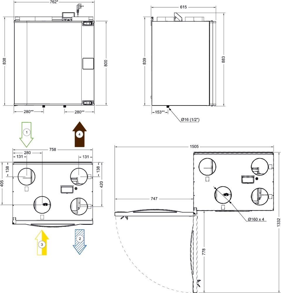
1Наружный воздух 2 Приточный воздух 3 Вытяжной воздух 4 Выбросной воздух
Приточно-вытяжная вентиляционная установка с рекуперацией тепла для жилых помещений с вентилируемой площадью до 240 м2. Лево- и правосторонние модели.
SAVE VTC 300 разработана для настенного монтажа в подсобных помещениях (прачечных, кладовых и тд.).
Корпус SAVE VTC 300 изготовлен из тепло-шумо изолированных сэндвич-панелей окрашенных в белый цвет. Установка подставляется с системой управления, с высокоэффективным противоточным рекуператором, фильтрами, с энергоэффективными вентиляторами с EC-двигателями, которые потребляют на 50% электроэнергии меньше по сравнению с традиционными двигателями переменного тока. Современные технологии обеспечивают низкие значения SFP (Specific Fan Power). Встроенный в вытяжном канале датчик влажности может использоваться для управления по потребности.
Все настройки и функции доступны на панели управления SAVECair, встроенной в лицевую панель. Панель представляет собой цветной сенсорный дисплей с удобным интерфейсом. Доступна опция подключения одной или нескольких внешних панелей управления. Также панель управления имеет отдельный пользовательский уровень для авторизованных монтажников и обслуживающих специалистов.
На главном экране панели управления отображается информация о расходе воздуха, температуре, качестве воздуха и активных функциях. Можно выбрать ручной и автоматический режим управления или выбрать предпочтительные параметры из предварительно настроенных пользовательских режимов.
Автоматический режим SAVECair имеет множество функций, которые регулируют поток воздуха по уровню СО2, присутствию, влажности, недельного расписания и т. д. Функция управления по потребности обеспечивает эффективную и экономичную работу и наилучшее качество воздуха. Аварийные символы будут указывать на возможные неисправности и выдавать прямые предупреждения, если что-либо необходимо исправить.
Установка имеет автоматическую функцию оттайки, которая может быть выбрана из 3-х различных режимов в зависимости от наружного воздуха и воздуха внутри помещения. Без предварительного нагревателя в «Пассивных домах», где дисбаланс не допустим, установки могут работать до -5°C. Без предварительного нагревателя, где дисбаланс допускается, установки могут работать до -15°C. При условиях эксплуатации ниже -15°C необходима установка предварительного нагревателя.
SAVE VTC 300 может быть доукомплектована электрическим догревателем.
Установка оснащена внешним соединительным коробом с предварительно подготовленными входами и выходами для простого монтажа и подключения внешних датчиков, нагревателей/охладителей.
Установка поставляется с панельными фильтрами низкого давления G4 для приточного и вытяжного воздуха. Панельный фильтр F7 и мешочный фильтр F7 для приточного воздуха доступны опционально. Панельный фильтр M5 доступен опционально для вытяжного воздуха.