-
Contents
-
Table of Contents
-
Bookmarks
Quick Links
User manual
4ch Million Pixels SD
Mobile DVR
USER MANUAL
Version 3.0
Summary of Contents for SD-MDVR SW-0001A
-
Page 1
User manual 4ch Million Pixels SD Mobile DVR USER MANUAL Version 3.0… -
Page 2: Table Of Contents
User manual CATALOGUE 1 Parts list …………………………. 4 2 Product introduction ………………………. 4 2.1 Product features ……………………..4 2.2 Main Functions ……………………..6 2.3 Parameter Sheet ……………………..7 2.4 Front Panel ……………………….
-
Page 3
User manual 4.7.2 Speed Alarm ……………………29 4.7.3 Acceleration ……………………30 4.7.4 Motion Detection …………………… 30 4.7.5 Voltage Alarm ……………………31 4.7.6 Serial Port Set ……………………32 4.7.7 PTZ ……………………….. 32 4.8. -
Page 4: Parts List
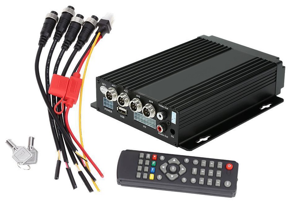
User manual 1 Parts list Quantit Device Type Name Unit Basic Basic+GPS/BD Basic+Gps/BD+3/4G MDVR ✔ ✔ ✔ Remote Control ✔ ✔ ✔ Power input wire 1 ✔ ✔ ✔ AV input wire ✔ ✔ ✔ AV output wire ✔ ✔ ✔…
-
Page 5
User manual Special File System Technology,Solving repeatedly wipe cause file fragmentation, solving SD card file system collapse, data loss and cannot find SD card and file garbled, ensure the integrity of the data. 8-33V Adaptive Wide Voltage input, Super Low Power Consumption Design; SD card storage (maximum support two pieces 128GB SD card. -
Page 6: Main Functions
User manual Main Functions Main Sub‐Item Instructions Video Channel 4Channel video + 4Channel Audio recording synchronously; Support 4*720P(1280*720),4*D1(704*576),4*HD1(704*288), 4*CIF(352*288) ; Resolution Each channel is individually adjustable. Image Quality 0‐7 levels, 0 is the highest level. OSD Overlays information such as date time and vehicle ID Recording Sub‐System Loop Rec Support SD card loop recording, loop cover previous video Record Mode Timed recording, alarm trigger recording and manual recording Support 1 channel and 4 channels preview. Support enlarge Preview video image when alarm trigger and video rear view trigger; Disk Space pre‐allocated Support disks overwritten function. overwritten Video Search Search video files anytime per day, type(n/a) Support 1 to 4 channels playback. Playback System Playback Support forward and backward play at the speed of: x2 ,x4,x8,x16. Support alarm spot search and time search. Graphical User GUI Setup system parameters with the remote control. Interface 8 channels electrical level alarm input for optional Input…
-
Page 7: Parameter Sheet
User manual Parameter Sheet Item Parameter Linux Language Chinese/English/Others (can be customized) Video Compression H.264 Compression Mode OSD Overlays information such as date time and vehicle ID Graphical User Can connect to external LED screen. Setup system parameters with the remote GUI Interface control. 4CH 720P AHD/ 4CH standard definition /2CH high definition+2CH standard Video Input definition mixed video input ,aviation plug Video Output 1CH CVBS+ VGA output for optional, 1.0Vp‐p, 75Ω, aviation plug Support 1 channel and 4 channels preview.,Support Manual/Alarm Trigger full Preview screen preview Resolution 720P/D1/HD1/CIF, MAX:4 channels of 720P Video Quality 0‐7 levels, 0 is the highest level, 7 is the lowest level. PAL: 100f/s , CCIR625 line,50field; NTSC: 120f/s, CCIR525 line,60field; CIF: 256Kbps ~ 1.5Mbps, 8 level video quality optional; Video Standard HD1: 600Kbps ~ 2.5Mbps, 8 level video quality optional; D1: 800Kbps ~ 3Mbps, 8 level video quality optional; 720P: 4Mbps‐6Mbps, 8 levels video quality optional The default setting is auto recording after power on. Timed recording, alarm Record Mode trigger recording and manual recording are supported.
-
Page 8
User manual 2pieces SD Card,each max 128GB SD Card, mirror recording to protect data from Storage loss Support USB flash disk updating,SD card upgrade , OTA remote upgrade Upgrade automatically Video File Format H.264 General video format Storage File System Special FAT32 File System Front panel supports USB port, support USB flash disk upgrade to backup; hard USB disk box USB port, can back up video data Video Search Search video by Record Time/Record Type etc Video Max support 4CH Replay /Stop/Fast Forward/Fast Reverse at same time Playback Playback Support x 2,x4,x8,x16. fast forward or fast backward play Safety Management User/Admin 2 Levels Different Passwords , support screen lock TTS Voice Support the TTS Voice Broadcast function Broadcast Extension Functions Serial Port Support kinds of Access Equipment such as LED Advertising, PTZ control, Oil Fuel Extension Sensor,etc. Adaptive wide power input, support Wide Voltage, Over‐load、Over‐voltage、 Power Management Short Circuit、Reverse Protection..Support Time Setting/Delay power off Voltage Input DC:+8V ~ +33V… -
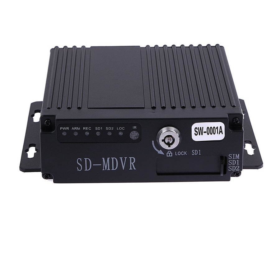
Page 9: Front Panel
User manual Front Panel ① ② ③ ⑤ ④ Front Panel items introduction Silk Item Name Functional Specification screen Power Indicator LED, LED on means powered has connected. Alarm Indicator LED, LED on means alarm event is happening. Video Recording Indicator LED.LED means In the recording SD card 1 Indicator LED, LED ON—Card exists but not recording, LED ○ FLASH—Card 1is recording, LED OFF—Card does not exist Indicators SD card 1 Indicator LED, LED ON—Card exists but not recording, LED FLASH—Card 2 is recording, LED OFF—Card does not exist SD Lock Indicator LED, LED ON—SD Lock is open. IR Remote ○ Infrared remote control receiving hole Receiver It’s used for unload hard disk. ○ Device will power off automatically if power on when HDD lock is SD Lock LOCK open.
-
Page 10: 4Ch Mdvr Back Panel
User manual 4CH MDVR Back Panel ① ② ③ ⑦ ⑤ ⑥ ④ 4CH MDVR Back Panel items introduction : Item Name Silk screen Functional Specification Video&Audio ○ 1‐4Channels, with DC 12V output, AV1-AV4 Input interface Video&Audio ○ Video&Audio output interface, with DC 12V output AV OUT Output interface ○ 3G Antenna Port With alarm input&output、 serial port etc.A more detailed ○ SENSOR definition see chapter 1.6.4 ○ USB Interface It’s used to import or export data or upgrade Input Voltage DC 8‐33V,…
-
Page 11: 8Ch Mdvr Back Panel
User manual 8CH MDVR Back Panel ① ② ③ ⑦ ⑤ ⑥ ④ 8CH MDVR Back Panel items introduction : Item Name Silk screen Functional Specification 1,2 Channel Video&Audio Input interface, with DC 12V AV1-2 output Video&Audio ○ AV3-4 3,4 Channel Video&Audio Input interface Input interface AV5-6 5,6 Channel Video&Audio Input interface AV7-8…
-
Page 12: Power Input Interface Pin Description
User manual 4 Pin aviation 6 Pin aviation plug plug FUNCTION FUNCTION +12V +12V Video Input Audio Input/output Audio Input Video Input/output Video Input Audio Input 2.6.2 Power Input interface pin description Pin Configurations FUNCTION Power- Power+ 2.6.3 I/O Interface Definition I/O Port pin configurations PIN DESCRIPTION FUNCTION…
-
Page 13: Remote Controller
User manual Remote Controller Power and Standby Button,Reserved To endter system setting 【 - 】 : 0 9 Key In the setting mode,0-9 is uses to selecet the 【 - 】 number of menu items.In playback mode,the keys to select Number Key single channel playback.
-
Page 14: Device Installation
User manual 3 Device Installation Power Cable Connection This MDVR use DC power supply, Wide operating range8 to 33V ★…
-
Page 15: Operation Interface Setup
User manual 5. The power cables must can stand beyond 60W.(For example, when the output voltage of car is 12V,the power cables must can bear 5A or more). 6. Please put the cover on the cables, the cover must be wear-resistant, heat-resistant, water-proof, grease-proof, in case of short circuit and open circuit.
-
Page 16: Search
User manual Search Query menu includes: Record, Log and Picture, …
-
Page 17: Video Search
User manual 4.1.1 Video Search **** Green color display indicates current day and time exist video file **** “Search Date”: Press the number key to enter date, default is current date. “Start Time”: Press the number key to enter date, default is 00:00. “End Time”: Press the number key to enter date, default is 23:59.
-
Page 18: Log Query
User manual 4.1.2 Log Query This menu is to query device operation and working log , you can choose the same type log via log categories. When select a single log, press the keys to quickly flip over, and press to turn to first page or last page.
-
Page 19: Terminal Setup
User manual 4.4.1 Terminal Setup By remote control input settings: device number, phone number, license plate number, the provincial domain ID, the City ID, terminal type, manufacturer ID, terminal ID, the device management (data in accordance with the Department of standards, Chinese input can use the soft keyboard input) …
-
Page 20: User Management
User manual 4.4.2 User Management “Password Enable”: You can enable or disable password authentication to access the menu. Modify or setup password of users and the administrator by remote control. **** ADMIN Pass : 111111, USER Pass : 000000 **** 4.4.3 Time Set This menu is to setup device parameters, such as date and time, etc.
-
Page 21: Parameters Management
User manual “Power mode”:press the number keys to select the type, the default is ignition mode. “Delay Off”: Press the number keys to enter the time, the default is 5 minutes, can be set to 1440 minutes “Screen time”: Press the number keys to enter the time, the default is 60 minutes, can be set to 0-1440 minutes “Power On”: Press the number key to enter time, setup the timer start time “Power Off”: Press the number key to enter time, setup the timer off time…
-
Page 22: Format
User manual 4.4.6 FORMAT Format Disk choice, device will reboot disk after confirming, log and pictures and other related info will be reserved. Attention: Device will format automatically when it starts, new SD card, can be formatted on the computer, in general, it doesn’t need format disk in DVR by manual.
-
Page 23: Main Stream
User manual “Video Type”: PAL / NTSC, press [OK] key to select. “Record Mode”: Auto / timer / alarm recording, press [OK] key to select. “Camera Type “: Can switch the status of standard definition , high definition or mixed camera input. “Resolution”:Set the resolution of VGA output.
-
Page 24: Sub-Stream
User manual “Enable”: open or close the channel of pre-recording function, press [OK] key to select. “Resolution”: CIF, HD1, D1 and 720P resolution for choosing, press [OK] key to select. “FPS”: 1-25 frame (P standard), 1-30 frame (N standard) channel recording frame rate for choosing. “Image quality”…
-
Page 25: Storage Management
User manual Move the cursor to “Timing Recording” and press [OK] button to set up the following timing list. **************************************************************************************** Timer recording start time is before the end time. **************************************************************************************** 4.5.5 Storage management “pre-recorded”: pre-recorded alarm recording time of 0-60 seconds to setup, press number keys to setup. “Alarm delay”: alarm delay recording time, 120-3600 seconds to set up, press number keys to setup.
-
Page 26: Center Setup
User manual 4.6.1 Center Setup Set Server IP and Port ; “Monitoring Center”:Set 3G /4G Video Center IP or domain,port information etc, “Network Type”:Set 3G network type, IP address/Domain optional; “Center IP”:3G Server IP/Domain setup. Press right key to enter keyboard interface,input the numbers via remote controller,then press [OK] for setting,;…
-
Page 27: Local Network Setup
User manual 4.6.2 Local Network Setup Device Local Network setup “IP””Mask””Gateway” “DNS1” ”DNS2””MAC”:IP,Mask,Gateway,MAC setting for LAN network testing. Attention: When net cable directly connect to the device, only can use 4PIN definition net cable (please see more definition in the addenda), otherwise it will lead device dead. 4.6.3 3/4G Setup 3G/4G Network Configuration …
-
Page 28: Wifi Setup
User manual 4.6.4 WIFI Setup “WIFI-EN”:WIFI On/Off Setting,Press [OK] for choosing; “Encr-EN”: WIFI encryption ON/Off Setting,press [OK] for choosing; “Au-Mode”: WIFI Authentication mode setting,Please choose same one with your router, “Enc-Type”: WIFI Encryption type setting,Please choose the one same with your router, “IP””Mask””Gateway”:WIFI IP/Mask/Gateway setting “SSID”: Input Your WIFI SSID, “PWD”: Same with your WIFI password,…
-
Page 29: Io Alarm
User manual 4.7.1 IO Alarm Each channel alarm enable/level/time delay/Linkage information setting; “Enable”:Alarm Trigger enable on/off and alarm type, press [OK] for changing; “Level”:Choose Alarm trigger level,High/Low Level optional,press [OK] for optional; “ Delay”:When alarm trigger,if need delay alarm trigger,time can be set to reduce error alarm, press [OK] for changing;…
-
Page 30: Acceleration
User manual “ Speed Source”: The method to get speed, GPS/Pulse Signal Optional, Press [OK] for changing; “ Pulse Number”:Must set Pulse factor for the standard if using Pulse to get car speed information,press Numbers for changing,can search vehicle data or constant speed by several times setting for a certain number “…
-
Page 31: Voltage Alarm
User manual “Threshold “: Main is area alarm percentage, generally set 1 or 2, representing 1% or 2% area change images move,it will trigger motion detection alarm. “Sensitivity”: 0-7 levels, 0 is the highest level, 7 is the lowest level. Generally suggest to set 1, the bigger number you choose ,the lower the sensitivity will be, then it’s not easy to alarm as well.
-
Page 32: Serial Port Set
User manual 4.7.6 Serial Port Set External Device parameter setting, can connect LED Advertisement/TTS/Oil/Sensor/POS etc ; “ Peripheral”:The external device type option,press [OK] For Changing; “ Baud Rate”:Choose Baud Rate of external device,press [OK] for changing; “ Data Bit”: Choose the Data bit of external device, press [OK] for changing; “…
-
Page 33: System Info
User manual 4.8. System Info System Info have 2 parts for detail information;can view by menu or Press INFO. 5 FAQ 5.1. Common problem Q:When Device issue appear,you are confused on how to solve it. A:Check Device Item No & Firmware Version,sent back to us with detail description of issue.Our Technical Team will handle it.
-
Page 34: Gps Related Faq
User manual Q:Video Output Lost A:1.Check situation of DVR:Device Input Power;Power Cable Connection;GND Connect to battery;fuse;RED & Yellow Cable of Power must connect together; 2.Check the Screen Power or Check if the Screen change to related AV Channel; 3.Check the connection of Video Output & Screen Cable; Q:Device keep Rebooting A:1)Check working power,if low power device will keep rebooting;…
-
Page 35: Client Software Faq
User manual A:1)Choose inside wireless module WCDMA,EVDO,TD-SCDMA, relative module setting is different then SIM Card is different, please make sure the module is corresponding with the SIM Card. 2)If Server IP & Port set correct,if 3G signal strong for dialing;3G dialing successfully or not; 3)Check 3G Antenna connection,dialing will be failed if 3G signal too weak;…
-
Page 36
User manual 3.If the camera takes an electricity power from the equipment directly, may be the equipment’s electric voltage isn’t enough to make camera work as usual; d) The cable that links this channel has problem Q: Can’t playback files on PC successfully? Possible reason is as follows: 1.Have never chosen a record file or document path;…
1
Parts list ……………………………………………………………………………………………………………………………………. 4
2
Product introduction …………………………………………………………………………………………………………………… 4
2.1
Product features ……………………………………………………………………………………………………………. 4
2.2
Main Functions …………………………………………………………………………………………………………….. 6
2.3
Parameter Sheet ……………………………………………………………………………………………………………. 7
2.4
Front Panel …………………………………………………………………………………………………………………… 9
2.5
4CH MDVR Back Panel ………………………………………………………………………………………………. 10
2.6
8CH MDVR Back Panel ……………………………………………………………………………………………….. 11
2.6.1
2.6.2
2.6.3
I/O Interface Definition …………………………………………………………………………………………. 12
2.7
Remote Controller ………………………………………………………………………………………………………. 13
3
Device Installation ……………………………………………………………………………………………………………………. 14
3.1
Power Cable Connection ……………………………………………………………………………………………… 14
4
Operation Interface Setup ………………………………………………………………………………………………………….. 15
4.1
User Loading ……………………………………………………………………………………………………………… 15
4.2
System Main Menu ……………………………………………………………………………………………………… 15
4.3
Search ……………………………………………………………………………………………………………………….. 16
4.1.1
Video Search ……………………………………………………………………………………………………….. 17
4.1.2
Log Query …………………………………………………………………………………………………………… 18
4.1.3
Picture Search ……………………………………………………………………………………………………… 18
4.4
System Setup ……………………………………………………………………………………………………………… 18
4.4.1
Terminal Setup …………………………………………………………………………………………………….. 19
4.4.2
User Management ………………………………………………………………………………………………… 20
4.4.3
Time Set ……………………………………………………………………………………………………………… 20
4.4.4
Power Management ………………………………………………………………………………………………. 20
4.4.5
Parameters Management ……………………………………………………………………………………….. 21
4.4.6
FORMAT ……………………………………………………………………………………………………………. 22
4.5.
REC Setup …………………………………………………………………………………………………………………. 22
4.5.1
Basic Setup ………………………………………………………………………………………………………….. 22
4.5.2
Main Stream ………………………………………………………………………………………………………… 23
4.5.3
Sub-stream ………………………………………………………………………………………………………….. 24
4.5.4
Time Record Setup ……………………………………………………………………………………………….. 24
4.5.5
Storage management …………………………………………………………………………………………….. 25
4.6.
Network Set ……………………………………………………………………………………………………………….. 25
4.6.1
Center Setup ………………………………………………………………………………………………………… 26
4.6.2
Local Network Setup ……………………………………………………………………………………………. 27
4.6.3
3/4G Setup ………………………………………………………………………………………………………….. 27
4.6.4
WIFI Setup ………………………………………………………………………………………………………….. 28
4.7.
Alarm Setup ……………………………………………………………………………………………………………….. 28
4.7.1
IO Alarm …………………………………………………………………………………………………………….. 29
CATALOGUE
User manual
User manual
4ch Million Pixels SD
Mobile DVR
USER MANUAL
Version 3.0
User manual
CATALOGUE
1
Parts list ……………………………………………………………………………………………………………………………………. 4
2
Product introduction …………………………………………………………………………………………………………………… 4
2.1
2.2
2.3
2.4
2.5
Product features ……………………………………………………………………………………………………………. 4
Main Functions …………………………………………………………………………………………………………….. 6
Parameter Sheet ……………………………………………………………………………………………………………. 7
Front Panel …………………………………………………………………………………………………………………… 9
4CH MDVR Back Panel ………………………………………………………………………………………………. 10
2.6
8CH MDVR Back Panel ……………………………………………………………………………………………….. 11
2.6.1
Audio/Video Interface Definition ……………………………………………………………………………. 11
2.6.2
Power Input interface pin description ……………………………………………………………………… 12
2.6.3
I/O Interface Definition …………………………………………………………………………………………. 12
Remote Controller ………………………………………………………………………………………………………. 13
2.7
3 Device Installation ……………………………………………………………………………………………………………………. 14
3.1
Power Cable Connection ……………………………………………………………………………………………… 14
4 Operation Interface Setup ………………………………………………………………………………………………………….. 15
4.1
User Loading ……………………………………………………………………………………………………………… 15
4.2
System Main Menu ……………………………………………………………………………………………………… 15
4.3
Search ……………………………………………………………………………………………………………………….. 16
4.1.1
Video Search ……………………………………………………………………………………………………….. 17
4.4
4.1.2
Log Query …………………………………………………………………………………………………………… 18
4.1.3
Picture Search ……………………………………………………………………………………………………… 18
System Setup ……………………………………………………………………………………………………………… 18
4.4.1
Terminal Setup …………………………………………………………………………………………………….. 19
4.4.2
User Management ………………………………………………………………………………………………… 20
4.4.3
Time Set ……………………………………………………………………………………………………………… 20
4.4.4
Power Management ………………………………………………………………………………………………. 20
4.4.5
Parameters Management ……………………………………………………………………………………….. 21
4.5.
4.4.6
FORMAT ……………………………………………………………………………………………………………. 22
REC Setup …………………………………………………………………………………………………………………. 22
4.5.1
Basic Setup ………………………………………………………………………………………………………….. 22
4.5.2
Main Stream ………………………………………………………………………………………………………… 23
4.5.3
Sub-stream ………………………………………………………………………………………………………….. 24
4.5.4
Time Record Setup ……………………………………………………………………………………………….. 24
4.5.5
Storage management …………………………………………………………………………………………….. 25
4.6.
Network Set ……………………………………………………………………………………………………………….. 25
4.6.1
Center Setup ………………………………………………………………………………………………………… 26
4.6.2
Local Network Setup ……………………………………………………………………………………………. 27
4.6.3
3/4G Setup ………………………………………………………………………………………………………….. 27
4.6.4
WIFI Setup ………………………………………………………………………………………………………….. 28
4.7.
Alarm Setup ……………………………………………………………………………………………………………….. 28
4.7.1
IO Alarm …………………………………………………………………………………………………………….. 29
User manual
4.7.2
Speed Alarm ………………………………………………………………………………………………………… 29
4.7.3
Acceleration ………………………………………………………………………………………………………… 30
4.7.4
Motion Detection …………………………………………………………………………………………………. 30
4.7.5
Voltage Alarm ……………………………………………………………………………………………………… 31
4.7.6
Serial Port Set ……………………………………………………………………………………………………… 32
4.8.
4.7.7
PTZ ……………………………………………………………………………………………………………………. 32
System Info ………………………………………………………………………………………………………………… 33
5 FAQ ………………………………………………………………………………………………………………………………………… 33
5.1.
Common problem ……………………………………………………………………………………………………….. 33
5.2.
GPS related FAQ ………………………………………………………………………………………………………… 34
5.3.
5.4.
5.5.
3G Wireless Module related FAQ ………………………………………………………………………………….. 34
Client Software FAQ …………………………………………………………………………………………………… 35
Other related questions ………………………………………………………………………………………………… 35
Introduction
The manual is about the features and specifications of one kind of car DVR, it is an integration of “4 monitoring and recording “, “Million Pixels Digital&Analog mixed car DVR”,
“wireless data transmission “.
In the manual it describes the functions and considerations of the modules ,the connector signal definitions in the back panel, the interface definition and user’s operations.More details,please check following directory.
State:
This manual may exist any technical describe inaccurate or misprint,also the contents will be update unscheduled without notice,new contents will be added in next version;
We’re subject to improve or update product description or program,if any difference,all depend on real goods,please understand.
User manual
1 Parts list
No Name
1 MDVR
2 Remote Control 1
3 Power input wire 1
4 AV input wire 4
5 AV output wire 1
6 Keys
7 GPS antenna
2
1
8 3G/4G antenna 1
9 8CH patch cord 4
10 Specification 1
11 Guarantee 1
12 Certification 1
Quantit y
1
Profile Display:
Unit set pcs pcs pcs pcs pcs pcs pcs pcs pcs pcs pcs
Device Type
Basic Basic+GPS/BD Basic+Gps/BD+3/4G
✔
✔
✔
✔
✔
✔
✘
✘
✔
✔
✔
✔
✔
✔
✔
✔
✔
✔
✔
✘
✔
✔
✔
✔
✔
✔
✔
✔
✔
✔
✔
✔
✔
✔
✔
✔
2 Product introduction
H.264 Compression Mode, Support 4CH real-time 720P Million Pixels AHD input and Analog
Standard Definition camera input, or 2CH HD input + 2CH SD input; Exclusive pre-allocate DVR
User manual
Special File System Technology,Solving repeatedly wipe cause file fragmentation, solving SD card file system collapse, data loss and cannot find SD card and file garbled, ensure the integrity of the data.
8-33V Adaptive Wide Voltage input, Super Low Power Consumption Design; SD card storage
(maximum support two pieces 128GB SD card. ) It can be completely resist car Vibration,Dust and others cause data corruption; Support GPS/BD/G-SENSOR ; High Reliability Aviation plugs,High Cost
Performance with reliable stability,simple and clear operation menu .
HIS Solution,H.264 Compression Mode, Many stream recording,4CH Video+2CH Audio Input,
Compatible with 4CH 720P/960P Mega Pixels Analog High Definition Camera input /2CH AHD High
Definition + 2CH Standard Definition mixed input / 4CH Analog Standard Definition Camera input.
Real-time HD Video Recording, 720P/D1/HD1/CIF for Optional,Adjustable Frame Rate Quality.
Professional Power Design for all kinds of Vehicles, 8-36V DC; Wide Voltage,
Over-load,Over-voltage,Short Circuit,Reverse Protection,Suitable for all kinds of vehicles.
Support DC 12V/2.5Amp output, it can offer power for cameras,mini monitor and some peripheral device.
HDD + SD card Data record storage (maximum support 2TB 2.5’’ hard disk and 128GB SD card. ) It can be completely resist car Vibration,Dust and others cause data corruption;
Watchdog Abnormal will trigger Restart Protection Function . It can better protect Device and Video.
Exclusive pre-allocate DVR Special File System Technology,Solving repeatedly wipe cause file fragmentation, and ensure the integrity of the data.
By accidents power-off protection function.Unique UPS Technology ensures the integrality of record when power failure occurs,even can for 10-15s.
Flame out Time-lapse Video Recording Function ( Highest support long delay time 24 hours.)
Auto Recording,Time Recording,Alarming Recording Modes for Different Request.
Display vehicle traffic status, Vehicle numbers ,Route, Super-low speed vehicle Information, Convenient management.
Support GPS/BD,G-sensor Modules Extension.
3channels RS232 +2channel RS485.
Superior network function, can configure menu through IE, support mobile SMS to configure parameters and obtain device information.
Support Video&Audio monitoring,2-way Intercom, PTZ control, manually Alarm,Overspeed,Geo Fence etc through remote control platform
8CH alarm inputs (Doors, lights, steering, braking, reversing and all types can be configured), Can support kinds of response linkages.
2CH alarm output, Support the linkage acousto-optic alarm, cut off fuel oil/power,etc .
Support Local Auto-photo when alarm input,device pictures preview function;
All Aviation plugs, Super stable, High Anti-shock,Easy installation Plug in and out.
Unique WINDOWS 8 interface, Easily Smart GUI Interface, Fluent system interface is intuitive and perfect.
Support SD card Remote Software Upgrade/OTA remote upgrade automatically, partition backup technology upgrade don’t crash.
Can be batch functional customization according to customer’s requirements;
Dimension and Weight Dimension : 112(W) x36(H) x138(D) mm , Weight: 360g
User manual
Main Sub‐Item
Recording
Sub‐System
Playback
System
GUI
Alarm
Optional functions
Others
Instructions
Video Channel
4Channel video + 4Channel Audio recording synchronously;
Resolution
Support 4*720P(1280*720),4*D1(704*576),4*HD1(704*288), 4*CIF(352*288);
Each channel is individually adjustable.
Image Quality 0‐7 levels, 0 is the highest level.
OSD Overlays information such as date time and vehicle ID
Loop Rec Support SD card loop recording, loop cover previous video
Record Mode Timed recording, alarm trigger recording and manual recording
Preview
Support 1 channel and 4 channels preview. Support enlarge
video image when alarm trigger and video rear view trigger;
Disk overwritten
Space pre‐allocated Support disks overwritten function.
Video Search Search video files anytime per day, type(n/a)
Support 1 to 4 channels playback.
Playback
Input
Output
Support forward and backward play at the speed of: x2 ,x4,x8,x16.
Support alarm spot search and time search.
Graphical User
Interface
Setup system parameters with the remote control.
8 channels electrical level alarm input for optional
Alarm linkage recording Active request the intercom One‐key phone calling functions,etc.
Max support 2ch level output
GPS Positioning Built‐in GPS/BD module: can sync record GPS information, trace replay.
PTZ Control
Serial Expand
Support Pelco‐D protocol 485 PTZ remote/local control,preset.
Support LED Advertisement PanelOil SensorPOSB us Station Broadcaster Car
OBD,ect.external devices.
G‐sensor, Record vehicle real‐time status.
G‐Sensor
TTS Voice
Broadcast
Support TTS voice broadcast function.
Can expand WIFI module,support 801.2b/g/n, 801.2a/c
Network
Built‐in EVDO/WCDMA/TD‐LTE/FDD‐LTE,etc, 3G/4G module.
ON/OFF
File System
System delay‐time power on/off;
DVR special file recording System Technology,Exclusive car record file system,space pre‐allocate,4ch single file Record,cyclic covering;To avoid the storage of the media causes file fragments, with high reliability and high stability;
User manual
Item Parameter
OS
Language
Video Compression
Linux
Chinese/English/Others (can be customized)
H.264 Compression Mode
GUI
OSD Overlays information such as date time and vehicle ID
Graphical User
Interface
Video Input
Can connect to external LED screen. Setup system parameters with the remote control.
4CH 720P AHD/ 4CH standard definition /2CH high definition+2CH standard definition mixed video input ,aviation plug
.
Video Output
1CH CVBS+ VGA output for optional, 1.0Vp‐p, 75Ω, aviation plug
.
Preview
Support 1 channel and 4 channels preview.,Support Manual/Alarm Trigger full screen preview
Resolution 720P/D1/HD1/CIF, MAX:4 channels of 720P
Video Quality 0‐7 levels, 0 is the highest level, 7 is the lowest level.
Video Standard
Record Mode
PAL: 100f/s , CCIR625 line,50field;
NTSC: 120f/s, CCIR525 line,60field;
CIF: 256Kbps ~ 1.5Mbps, 8 level video quality optional;
HD1: 600Kbps ~ 2.5Mbps, 8 level video quality optional;
D1: 800Kbps ~ 3Mbps, 8 level video quality optional;
720P: 4Mbps‐6Mbps, 8 levels video quality optional
The default setting is auto recording after power on. Timed recording, alarm trigger recording and manual recording are supported.
Audio
Audio Input
Audio Output
4CH ,Aviation Plug
2CH,Front port is earphone port ,rear port connects to BNC connector. The output level: 1V ‐ 2V
Compression G.726 compression, 8KB/s speed
Alarm Input
Alarm Output
Communication Interface
8CH IO Alarm Input, 1CH AD input, pulse speed input; Support alarm linkage function
2CH Relay Alarm Output, Support the linkage acousto‐optic alarm, cut off fuel oil/power,etc
1CH RS232, support extension device, such as POS machine, Oil Feul sensor, LED advertising screen , etc.
Wireless transfer
Position
1CH 485 interface, can connect PTZ,etc.
Support Built‐in 3G/4G network, WCDMA,CDMA2000,TDD‐LTE,FDD‐LTE…
Support Built‐in/External WIFI, Compatible with GPRS,EDGE
Support Built GPS/BD Module,can make playback analysis of vehicle routing
G‐Sensor Support G‐sensor
User manual
Video
Storage
Video
Playback
Storage
Upgrade
File Format
2pieces SD Card,each max 128GB SD Card, mirror recording to protect data from loss
Support USB flash disk updating,SD card upgrade , OTA remote upgrade automatically
H.264 General video format
File System Special FAT32 File System
USB
Front panel supports USB port, support USB flash disk upgrade to backup; hard disk box USB port, can back up video data
Video Search Search video by Record Time/Record Type etc
Max support 4CH Replay /Stop/Fast Forward/F ast Reverse at same time
Playback
Support x 2,x4,x8,x16. fast forward or fast backward play
Safety Management
Extension
Functions
User/Admin 2 Levels Different Passwords , support screen lock
TTS V oice
Broadcast
Serial Port
Extension
Power
Management
Support the TTS Voice Broadcast function
Support kinds of Access Equipment such as LED Advertising, PTZ control, Oil Fuel
Sensor,etc.
Adaptive wide power input, support Wide Voltage, Over‐load、Over‐voltage、
Short Circuit、Reverse Protection..Support Time Setting/Delay power off
Voltage Input DC:+8V ~ +33V
Voltage &
Power
Consumpti on
Working
Environme nt
Voltage Output
Power‐off
Protection
Power
Consumption
Temperature ‐20 to +70
℃
Humidity
[email protected]
UPS Technology,All video information can be saved automatically when the power is cut off, and make sure that all the files can not be damaged.
Normal Working <5W Stand‐by Status <0.5W
20% to 80%
Size 140(W) x42(H) x142(D) mm others
Net Weight 440g
***** Above parameters any changes,please refer to actual product *****
User manual
① ② ③ ⑤
④
Front Panel items introduction
Silk
Item Name screen
Functional Specification
LED
Indicators
PWR
ARM
REC
SD1
SD2
Power Indicator LED, LED on means powered has connected.
Alarm Indicator LED, LED on means alarm event is happening.
Video Recording Indicator LED.LED means In the recording
SD card 1 Indicator LED, LED ON—Card exists but not recording, LED
FLASH—Card 1is recording, LED OFF—Card does not exist
SD card 1 Indicator LED, LED ON—Card exists but not recording, LED
FLASH—Card 2 is recording, LED OFF—Card does not exist
SD Lock Indicator LED, LED ON—SD Lock is open.
LOC
IR Remote
Receiver
IR
Infrared remote control receiving hole
○
SD Lock LOCK
It’s used for unload hard disk.
Device will power off automatically if power on when HDD lock is open.
It’s used for unload SD card or SIM card
○
SD card slot SD
○
Label
Equipment Type Label
** Status LED will alternate loop flash when device power on, it will quick loop flash when device is upgrading **
User manual
2.5 4CH MDVR Back Panel
① ②
③
⑦
⑥
4CH MDVR Back Panel items introduction:
④
⑤
Item Name
Video&Audio
Input interface
Video&Audio
Output interface
Silk screen
AV1-AV4
AV OUT
Functional Specification
1‐4Channels, with DC 12V output,
Video&Audio output interface, with DC 12V output
○
3G Antenna Port
3G
○
With alarm input&output、serial port etc.A more detailed definition see chapter 1.6.4
○
USB Interface
USB
Power Input
interface
POWER
It’s used to import or export data or upgrade
Input Voltage DC 8‐33V,
Red
cable connect power positive,
Black cable connect power negative;
Yellow
line ACC signal cable.
○
GPS Antenna Port
GPS
User manual
2.6 8CH MDVR Back Panel
① ②
③
⑦
⑥
8CH MDVR Back Panel items introduction:
④
⑤
Item Name
Video&Audio
Input interface
Silk screen
AV1-2
AV3-4
AV5-6
AV7-8
Functional Specification
1,2 Channel Video&Audio Input interface,
with DC 12V output
3,4 Channel Video&Audio Input interface
5,6 Channel Video&Audio Input interface
7,8Channel Video&Audio Input interface
Video&Audio
Output interface
○
3G Antenna Port
AV OUT Video&Audio output interface, with DC 12V output
3G
○
I/O SENSOR
With alarm input&output,serial port etc.A more detailed definition see chapter 2.6.3
○
USB Interface
Power Input
interface
USB
POWER
It’s used to import or export data or upgrade
Input Voltage DC 8-33V,
Red
cable connect power positive,
Black cable connect power negative;
Yellow
line ACC signal cable.
○
GPS Antenna Port
2.6.1 Audio/Video Interface Definition
The 4CH MDVR support channel AV1~ AV4, it’s Video&Audio Input interface use 4 Pin aviation plug, and the 8CH MDVR support channel AV1~ AV8, it’s Video&Audio Input interface use 6 Pin aviation plug.
Their Video&Audio Output interface arm the same, use 4 Pin aviation plug. The aviation plug can adapt severe environment in the vehicles.
PIN DESCRIPTION
User manual
4 Pin aviation plug
PIN FUNCTION
1 +12V
2 GND
3 Audio Input/output
4 Video Input/output
2.6.2 Power Input interface pin description
6 Pin aviation plug
PIN FUNCTION
1 +12V
3
4
Audio Input
Video Input
Pin Configurations PIN FUNCTION
1 Power-
1 2
2 Power+
3 ACC
3 4
4 NC
2.6.3 I/O Interface Definition
I/O Port pin configurations
1 3 5 7 9 11 13 15
2 4 6 8 10 12 14 16
PIN DESCRIPTION
PIN FUNCTION
1 RS232-TX
3 RS485-A
5
7
Alarm in8
Alarm in 6
9
11
Alarm in 4
Alarm in 2
13 Alarm out 2
15 +12V
PIN FUNCTION
2 RS232-RX
4 RS485-B
6 Alarm in 7
8
10
12
Alarm in 5
Alarm in 3
Alarm in 1
14 Alarm out 1
16 GND
User manual
Power and Standby Button,Reserved
【 - 】
Number Key
To endter system setting
【 - 】
Key
:
In the setting mode,0-9 is uses to selecet the number of menu items.In playback mode,the keys to select single channel playback.
Delete Button
Multi Channel Display Button,press this button can switch between multi channels and single channel display
Direction button,When Operating menu, press this button to move cursor.
Exit button,
Forward buton,In play mode,Press this button to select
2/4/8/16 times speed to play forward .
Rewind buton,In play mode,Press this button to select
2/4/8/16 times speed to play backward.
Stop button
PAUSE/STEP button
In normal mode, press this button enter play mode directly
User manual
3 Device Installation
3.1 Power Cable Connection
This MDVR use DC power supply, Wide operating range8 to 33V
★ Use ignition switch to control video record delay time working
Red wire connect positive of the car battery, black wire connect negative,while yellow wire connect independent ignition switch or independent positive.
★ Do not use ignition switch to control video record delay time working(Office Test also using
this mode)
The red and yellow wire connect together to connect the battery positive,Black wire to connect the battery negative .
Attention
1. The recorder is DC power supply; please attention the positive and negative polar.
2. The voltage is 8V~36V.Do not insert voltage that beyond this range. Under low voltage the recorder doesn’t work, under high voltage will be harm to the recorder.
3. Please make sure the recorder is connect with the car power directly. Do not connect with the generator, the instantaneous voltage will harm to the recorder.
4. The initial power will beyond 30W when the DVR connect with the Camera (the consumed power is different due to the connect with different device), the power supply must beyond 30W.
User manual
5. The power cables must can stand beyond 60W.(For example, when the output voltage of car is 12V,the power cables must can bear 5A or more).
6. Please put the cover on the cables, the cover must be wear-resistant, heat-resistant, water-proof, grease-proof, in case of short circuit and open circuit.
7. Please install a 10A fuse box near the battery output positive polar for fear of the short circuit will damage the power supply.
4 Operation Interface Setup
When the password switch is set to “Off”: The host start and press [OK] key, will direct access to the main menu..
When the password switch is set to “On”: Move the cursor to “landing” column, Press [OK] key, then can enter the main menu.
**********************************************************************************
The administrator default password is 111111(or device number –before changed the password available);
User default password is 000000, only have query permissions;
**********************************************************************************
The main menu includes: Search, System setup, Rec setup, Network setup, Alarm setup and Peripheral,
System Information, as below:
User manual
4.3 Search
Query menu includes: Record, Log and Picture,
User manual
4.1.1 Video Search
**** Green color display indicates current day and time exist video file ****
“Search Date”: Press the number key to enter date, default is current date.
“Start Time”: Press the number key to enter date, default is 00:00.
“End Time”: Press the number key to enter date, default is 23:59.
“Record Type”: Press the [OK] button to select the query type: All videos Alarm recording. Default is
All videos.
“Storage Media”: Press the [OK] button to select: all disks, disk 1, disk 2.
“Search”:Move the cursor to “Search” button, press the [OK] key to enter the search results interface.
Press the arrow keys to select the video you want, press the keys to quickly flip, press
to turn to first page or last page, press the play button to play the video, press [ESC] key to return to the previous menu。
Press the arrow keys to select “Home”, “Previous”, “Next”, “Last” and press [OK] button to display the next page information.
User manual
4.1.2 Log Query
This menu is to query device operation and working log , you can choose the same type log via log categories.
When select a single log, press the
or last page.
4.1.3 Picture Search
keys to quickly flip over, and press
This menu is mainly for searching the screenshot pictures.
to turn to first page
Zoom up single full screen will auto screen capture by default , it will be triggered by the alarm linkage or manually operate.
**** Pictures and device log all save in the second partition ****
Under System Setup menu includes: Power, time setup, user setup, terminal setup (menu setup and modifying need to choose save to take effect)
User manual
4.4.1 Terminal Setup
By remote control input settings: device number, phone number, license plate number, the provincial domain ID, the City ID, terminal type, manufacturer ID, terminal ID, the device management (data in
accordance with the Department of standards, Chinese input can use the soft keyboard input)
User manual
4.4.2 User Management
“Password Enable”: You can enable or disable password authentication to access the menu.
Modify or setup password of users and the administrator by remote control.
**** ADMIN Pass : 111111, USER Pass : 000000 ****
4.4.3 Time Set
This menu is to setup device parameters, such as date and time, etc.
“Date Type”: Different date format for choosing.
“Date”: Press the number keys to enter current date.
“Time Synchronization”: calibration mode: GPS, NTP and other school models available.
“Time Zone”: Setup the time zone of the location of the device
“Timeout”: optional remote control does not operate the exit time
“Real Time”: Press the number key to enter the current time
4.4.4 Power Management
This menu is to setup Power management modes and power distribution.
User manual
“Power mode”:press the number keys to select the type, the default is ignition mode.
“Delay Off”: Press the number keys to enter the time, the default is 5 minutes, can be set to 1440 minutes
“Screen time”: Press the number keys to enter the time, the default is 60 minutes, can be set to 0-1440 minutes
“Power On”: Press the number key to enter time, setup the timer start time
“Power Off”: Press the number key to enter time, setup the timer off time
4.4.5 Parameters Management
“Import”:Import parameters from HDD or SD Card to current device.Import the system configuration parameters which has set up and restore the factory settings to the factory states
“Export”:Export current device parameters to HDD or SD Card;
“Default”:Default to factory setting; This operation will clear all the setting on the device.
If quantity Devices with same setting,please using Parameter Export/Import for configuration, after setting one device, export these parameters to U-Disk or SD Card then import to other rest devices to be fast setting.
User manual
4.4.6 FORMAT
Format Disk choice, device will reboot disk after confirming, log and pictures and other related info will be reserved.
Attention:
Device will format automatically when it starts, new SD card, can be formatted on the computer, in general, it doesn’t need format disk in DVR by manual.
4.5. REC Setup
Recording setup menu includes: basic setup, Main stream, Sub stream, time recording, Storage management(configuration and modification must select Save to take effect)
4.5.1 Basic Setup
This menu is to setup the basic video, audio and video parameters and can change into standard definition, AHD high definition and mixed mode.
User manual
“Video Type”: PAL / NTSC, press [OK] key to select.
“Record Mode”: Auto / timer / alarm recording, press [OK] key to select.
“Camera Type “: Can switch the status of standard definition , high definition or mixed camera input.
“Resolution”:Set the resolution of VGA output.
“ Layout”: optional: Single, 2-channel, 4 grids, nine grids and other video channel layout.
“Packket time”:The time of a single record file.
Attention :
If the camera type and DVR setting mode(AHD HD/Analog/Mixture) don’t match, then it will show
“video lost”, In Mixture mode, 1,2CHANNEL is AHD high definition input, 3,4CHANNEL is analog standard definition input;
4.5.2 Main Stream
This manual is to setup the code stream and definition of video channel.
User manual
“Enable”: open or close the channel of pre-recording function, press [OK] key to select.
“Resolution”: CIF, HD1, D1 and 720P resolution for choosing, press [OK] key to select.
“FPS”: 1-25 frame (P standard), 1-30 frame (N standard) channel recording frame rate for choosing.
“Image quality” setup video quality under different resolution, 4-speed adjustable.
“Audio” setup the audio recording on or off.
****************************************************************************************
According to the storage space and quality requirements, the resolution of each channel and stream can be configured individually
****************************************************************************************
4.5.3 Sub-stream
This menu is used to set the parameters of the transmission stream.
“Resolution” Setup the transmission resolution, press [OK] key to enter.
“FPS” Setup the transmission time frames, press [OK] key to enter.
“Image quality” setup transmission quality grade, press [OK] key to enter.
****************************************************************************************
Sub-stream is the code stream which device upload via 3G/4G, high definition main code stream can be chose in the client-side platform
****************************************************************************************
4.5.4 Time Record Setup
Setup the timer recording time periods, everyday can be set to two periods.
User manual
Move the cursor to “Timing Recording” and press [OK] button to set up the following timing list.
****************************************************************************************
Timer recording start time is before the end time.
****************************************************************************************
4.5.5 Storage management
“pre-recorded”: pre-recorded alarm recording time of 0-60 seconds to setup, press number keys to setup.
“Alarm delay”: alarm delay recording time, 120-3600 seconds to set up, press number keys to setup.
“Alarm Fime”: The storage time of alarm file, 3-45 days to set up, press number keys to setup.
4.6. Network Set
Including: Center setup,Local Network , dialing setup,WIFI setup.
User manual
4.6.1 Center Setup
Set Server IP and Port ;
“Monitoring Center”:Set 3G /4G Video Center IP or domain,port information etc,
“Network Type”:Set 3G network type, IP address/Domain optional;
“Center IP”:3G Server IP/Domain setup. Press right key to enter keyboard interface,input the numbers via remote controller,then press [OK] for setting,;
“Port”:Communication port between 3G device and Server,must be same with server configuration;
Remind:
In “ Info “ interface, W connected : it means device connected server already; B connected : it means device connected ministerial standard platform already, Connected : it means two platforms both connected device successfully.
User manual
4.6.2 Local Network Setup
Device Local Network setup
“IP””Mask””Gateway” “DNS1” ”DNS2””MAC”:IP,Mask,Gateway,MAC setting for LAN network testing.
Attention:
When net cable directly connect to the device, only can use 4PIN definition net cable (please see more definition in the addenda), otherwise it will lead device dead.
4.6.3 3/4G Setup
3G/4G Network Configuration
“Enable”:3G/4G On/Off Setting,Press [OK] for choosing;
“Type”:3G/4G Type setting,WCDMAEVDOTD-SCDMATD-LTE , FDD-LTE, press [OK] for choosing,
“APN”:Set 3G/4G APN,Press [OK] Input, enter into input page to set the information
“User”, “Password”:SIM Card Network Operation User and Password, Press [OK] for setting ;
User manual
4.6.4 WIFI Setup
“WIFI-EN”:WIFI On/Off Setting,Press [OK] for choosing;
“Encr-EN”: WIFI encryption ON/Off Setting,press [OK] for choosing;
“Au-Mode”: WIFI Authentication mode setting,Please choose same one with your router,
“Enc-Type”: WIFI Encryption type setting,Please choose the one same with your router,
“IP””Mask””Gateway”:WIFI IP/Mask/Gateway setting
“SSID”: Input Your WIFI SSID,
“PWD”: Same with your WIFI password,
****************************************************************************************
According to the specific configuration of WIFI network environment, please pay attention to check the accuracy of the characters and the IP address.
IP address set by WIFI and local network can not be in the same network segment.
****************************************************************************************
4.7. Alarm Setup
Including: IO,Speed, Acceleration, Motion Detection, Voltage, Serial Setting and PTZ.
User manual
4.7.1 IO Alarm
Each channel alarm enable/level/time delay/Linkage information setting;
“Enable”:Alarm Trigger enable on/off and alarm type, press [OK] for changing;
“Level”:Choose Alarm trigger level,High/Low Level optional,press [OK] for optional;
“ Delay”:When alarm trigger,if need delay alarm trigger,time can be set to reduce error alarm, press [OK] for changing;
“ Record”:Record set when alarm trigger, press [OK] for changing;
“ Linkage”:Linkage set when alarm trigger, press[OK] for changing;
“Preview”:when alarm trigger the Channel will be full screen for preview,can realize Car Reversing,Door open alarm etc, Press [OK] for changing;
4.7.2 Speed Alarm
High/Low Speed or illegal driving alarm can be set.
User manual
“ Speed Source”: The method to get speed, GPS/Pulse Signal Optional, Press [OK] for changing;
“ Pulse Number”:Must set Pulse factor for the standard if using Pulse to get car speed information,press
Numbers for changing,can search vehicle data or constant speed by several times setting for a certain number
“ Unit”: Driving Speed Unit,Press [OK] For Changing Setting
“Timeout Parking””Low Speed Alarm” ”Low Speed Warning””High Speed Warning” :by Enable to open or close alarm function,Level setting for alarm trigger response speed and time; Delay: alarm time ;Record: if recording when alarm appear;Linkage: When alarm occurs if linkage with alarm output;
4.7.3 Acceleration
SET G-sensor information of alarm threshold and linkage actions.
Before configuration, need to calibrate the current state first, then modify the alarm threshold.
4.7.4 Motion Detection
This menu is to set the image changes and the parameters of the object in the video pictures.
User manual
“Threshold “: Main is area alarm percentage, generally set 1 or 2, representing 1% or 2% area change images move,it will trigger motion detection alarm.
“Sensitivity”:0-7 levels, 0 is the highest level, 7 is the lowest level. Generally suggest to set 1, the bigger number you choose ,the lower the sensitivity will be, then it’s not easy to alarm as well.
Specific configuration parameters can depend on actual situation of the scene, such as illumination, detection area range and so on, to achieve the optimal effect.
4.7.5 Voltage Alarm
Low/High Voltage alarm.
Voltage abnormal delay shutdown: it means the voltage is kept below 8V, automatic shutdown time, this can effectively protect the battery, to avoid abnormal conditions caused by the battery voltage shortage, prolong the service life of the battery.
User manual
4.7.6 Serial Port Set
External Device parameter setting, can connect LED Advertisement/TTS/Oil/Sensor/POS etc ;
“ Peripheral”:The external device type option,press [OK] For Changing;
“ Baud Rate”:Choose Baud Rate of external device,press [OK] for changing;
“ Data Bit”: Choose the Data bit of external device, press [OK] for changing;
“ Stop Bit”:Choose the Stop bit of external device, press [OK] for changing;
“ Check Bit”:Choose the Check bit of external device, press [OK] for changing;
“Control Bit”: Choose Control bit of external device, press [OK] for changing;
4.7.7 PTZ
PTZ Camera parameter configuration
“ Protocol Type”:The Protocol of PTZ Camera support option,Press [OK] for changing;
“ ADD Code”:choose PTZ Camera Address code,press Number for changing;
“ Preset”:Choose PTZ Camera Preset code,press number for changing;
User manual
4.8. System Info
System Info have 2 parts for detail information;can view by menu or Press INFO.
5 FAQ
5.1. Common problem
Q:When Device issue appear,you are confused on how to solve it.
A: Check Device Item No & Firmware Version,sent back to us with detail description of issue.Our
Technical Team will handle it.
More detail you described,easier for us to solve it quickly.
User manual
Q:Video Output Lost
A: 1.Check situation of DVR:Device Input Power;Power Cable Connection;GND Connect to battery;fuse;RED & Yellow Cable of Power must connect together;
2.Check the Screen Power or Check if the Screen change to related AV Channel;
3.Check the connection of Video Output & Screen Cable;
Q:Device keep Rebooting
A: 1)Check working power,if low power device will keep rebooting;
2) HDD/SD Card error, remove storage device and turn on device checking;
Q: If the video input interface of the device and camera is different.
A: The DVR is using 4 needle type port, the camera is BNC port or Aviation, if it is different, please use the X-over to connect, or connect according to the DVR Line sequence definition
Q:Device on with HDD but not recording;
A: 1)Check SD/HDD if format;if not please enter Main GUI—System Set—Format,format HDD/SD Card;
2)If close Recording ,or set Timed Recording mode, if yes it won’t recording if not the time set
3)If the HDD is connect well, if the HDD/SD light is on.
Q: Video files lost, or there is no video files at a certain period time.
A: 1. Analysis the lost video and ensure the lost time period.
2. Confirm if the DVR was opened at that time, such as crashed midway park, loading and unloading ect.
And the device didn’t set the delay recording
Q: Can not control the Car PTZ, can not rotate to all direction.
A: If the agreement and Baud rate of the PTZ is setting right,if the address code is corresponding, if the video channel is setting to max when control the PTZ. Like if is control the first channel, then must set the first channel image to be max.
5.2. GPS related FAQ
Q: With GPS but no GPS coordinate Information
A :1)Check if GPS module exist;
2)Check GPS Antenna connection,suggest install on the outside place with strong signal;
3)If testing in office, suggest put GPS Antenna out of window;
4)If working environment not good will related to no GPS Information or wrong information;
Q:Deviation of GPS Location on Map?
A :The signal is effective if the GPS module has been positioning, there are so many reasons caused bias, government restriction, permissible error, GPS signal break off, The actual satellite map error occurred for the security, GPS Correction can solve the problem.
5.3. 3G Wireless Module related FAQ
Q:If using 3G ,what should we concern?
User manual
A: 1)Choose inside wireless module WCDMA,EVDO,TD-SCDMA, relative module setting is different then SIM Card is different, please make sure the module is corresponding with the SIM Card.
2)If Server IP & Port set correct,if 3G signal strong for dialing;3G dialing successfully or not;
3)Check 3G Antenna connection,dialing will be failed if 3G signal too weak;
4)Check SIM Card 3G Flow
Q:When meet device offline or no video,what should be done first?
A: 1)Press INFO key to enter the system Info page,check if SIM Card exist,3G signal and dialing status,Antenna connection,Check SIM Card 3G Flow,change to a new SIM Card check again;
2)3G Signal strong but dialing fail,check if center IP & Port set correct;
3)Check if Device ID already be occupied;
Q:3G Signal is intermittent, video get stuck ?
A: At present, signal coverage of the WCDMA and EVDO is very wide, but still there are some mountain area signal is weak, this will influence. Then check if the frame rate in Sub-stream setting is too high.
Q:WIFI Signal 60/100,connect failure;
A: General condition, connection is no problem when the signal intensity up to 60/100 if WIFI setup are right. If the device can not be found in LAN, then you should check if setting SSID and password, IP Address, besides, check the Encryption Type and authentication mode if setting according to requirements.
5.4. Client Software FAQ
Q:Device working but can not see Vehicle and video on client software
A: 1)Check if Center Server running and device Number if using;
2)Check Server IP and Port parameter setting;
3)Check is using 3G or WIFI for connecting, if 3G check the 3G Model WCDMA or EVDO and related
SIM card,3G antenna connect normally/APN setting/Center No. setting;
If it still can not work,please offer the most detailed information to us for technical support
Q:Device Online but can not see video
A: 1)Please set Low Sub-stream,when sub-stream set high it will effect the transmission because of the network;
2)Network environment not good;
Q: Device works well in the Client, but cannot see the video a period time later.
A:1.
Check if connect to server successfully on device, if dialing probably SIM Card no 3G Flow,change another SIM card for testing;
2.Check if Device Number be changed,if yes,need add device to server again;
3.If still can not view video after previous 2 steps,please check if 3G module error;
5.5. Other related questions
Q: Video Lost in certain channel?
A: Possible reasons are as follows
1. This channel has no video input
2.The camera of this channel breaks down or work abnormality
User manual
3.If the camera takes an electricity power from the equipment directly, may be the equipment’s electric voltage isn’t enough to make camera work as usual; d) The cable that links this channel has problem
Q: Can’t playback files on PC successfully?
A: Possible reason is as follows:
1.Have never chosen a record file or document path; please choose the path that records file first before playback.
Q: Remote control not works?
A: Probably of the reasons are as follows:
1.The remote control didn’t pack battery;
2.2.The remote control damages;
3.Device damages.
Q: During playback, the map doesn’t show?
A: Possible reasons are as follows: Net cable did not connect to PC; Net works, but the computer can not get to the Internet;
Q: When SD card and HDD records, How is the record coverage?
A: SD card and HDD will record circularly for each other. When they are full, they will delete the original video records respectively.
Download Operation & user’s manual of SD-MDVR SW-0001A DVR for Free or View it Online on All-Guides.com.

1

2

3

4

5

6

7

8

9

10

11

12

13

14

15

16

17

18

19

20

21

22

23

24

25

26

27

28

29

30

31

32

33

34

35

36

User manual
4ch Million Pixels SD
Mobile DVR
USER MANUAL
Version 3.0
Предупреждение: я не спец, выражаю мысль, как могу. Вывод сделан из личного наблюдения и скудных знаний. Не нужно брызгать в меня ядовитой слюной, если я не правильно что-то озвучил. Лучше просто поправьте меня и я откорректирую текст.
Итак, подведу итоги по:
Регистратор SD-MDWR SW-0001.
Сравнение 2-х камер сделаю следующей записью.
Буду краток 
В общем до полевых тестов дело не дошло, так как на данном этапе уже стало всё понятно.
Что оно из себя представляет:
4 канала видео — разрешение стандартное (для аналогового) — это:
— D1 – так называемое «full resolution»(704х576 точек);
— HD1 – половина кадра (704×288 точек );
— CIF – “Common Intermediate Format” или 1/4 кадра (352×288 точек)
А я вам скажу — это нормально ))) Просто все привыкли к фуллХД. Я промониторил нормальных производителей с аналогичными региками. И цены там даже и не 100 долларов, а намного больше. А разрешение картинки такое же.
Вы сами настраиваете разрешение, качество и кадры.
При чем вы не сможете писать сразу 4 канал D1 высокое 25 к/с. И даже 3. И даже 2
Имея 2 камеры по 600 твл я смог запустить эту шайтан-машину только если CH1 — D1 высокое 25кс, а CH2 HD1 высокое 25кс. Или CH1 — D1 высокое 25кс, а CH2 — D1 среднее 12кс.
По умолчанию стояли все 4 канала на самом минимуме.
В настройках присутствуют: постоянная запись, по расписанию, от концевиков; вкл-выкл каналы, сетевые настройки, качество видео на канал, разбивка (3,5,15 и тд) и перезапись файлов, форматирование флеш, экспорт/бекап файлов в AVI и родной формат, ну и стандартные (время, дата, язык и тд). К стати язык только инглишь и китай.
Регик не нагрелся за 8 часов работы.
С 11:00 до 19:00 было записано более 600 файлов по 3 минуты.
1й канал D1 H 25кс — 498Мб
2й канал HD1 M 25кс — 412Мб
3й и 4й пустые каналы — 629Мб (забыл отключить)
Бежим далее:
— нет экспорта на usb. Хотя сам разъем присутствует. экспорт осуществляется на ту же карту, куда пишет.
— доп модули, доступные в следующих версиях, не добавляются. прошивка захламлена ненужными параметрами и «функциями», которых на данной базовой модели нет и не будет никогда
— ооочень слабый проц. видео скачет. это даже не таймлапс )) регистратор не может не то, чтобы нормально и корректно писать хотя бы один канал, он в режиме записи не может шустро переварить даже «бегание» по меню настроек
— на 16Г флешке 10 класса после экспорта файлов иногда подвисал и не перезагружался.
— при попытках подружиться с USB флехой упорно отрыгивал ее, матерясь фразой «USB not found». При этом входил в ступор и перезагружался.
Итог: Выкину на авито, мож кому на дачу пригодится. Оставил бы себе это чудо, если бы оно писало без скачков.
Выкладываю видос. Следом выложу запись по обеим камерам (корея vs китай).
И таки да! На этом не останавливаюсь, буду искать другой рег в близком ценовом диапазоне.
Так что, ждите продолжение)