Please check that the delivered product is the correct item you ordered.
Please do not begin operating this product before you read this instruction manual
Notice:
Please ensure that this instruction manual is given to the final user of the instrument.
Preface: This instruction manual is meant for those who will be involved in the wiring, installation, operation and routine
maintenance of the SR90 series (SR91, SR92, SR93 and SR94). It describes matters to be attended to in handling
the SR90 series, how to install it, its wiring, its functions and operating procedures. Keep this manual at the work
site while handling the instrument and follow the guidance provided herein
1. Safety Rules……………………………………………………………………..2
2. Introduction…………………………………………………………………….. 3
2-1. Check before Use…………………………………………………………3
3-1. Installation Site……………………………………………………………4
3-2. Mounting…………………………………………………………………… 4
3-4. Wiring………………………………………………………………………. 6
3-5. Terminal Layout…………………………………………………………. 7
5-1. Parameter Flow………………………………………………………….. 9
(3) AT (Auto Tuning)………………………………………………………12
(5) Set Value Bias………………………………………………………….. 13
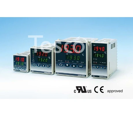
SR90 Series
(SR91, SR92, SR93, SR94)
Digital Controller
Instruction Manual
Thank you for purchasing a Shimaden product.
thoroughly and understand its contents.
Contents
(2) Setting of Output………………………………………………………15
(3) Setting of Event………………………………………………………. 16
6-1. Events……………………………………………………………………..19
6-4. P.I.D……………………………………………………………………….19
6-5. Manual Reset………………………………………………………….. 20
6-10. Soft Start………………………………………………………………… 20
Attended to………………………………………………………………21
9. Specifications…………………………………………………………… 24~25
— 1 —
SR90F-1AE
Dec. 2001
Солнечный тепловой контроллер является обязательным элементом гелиосистем с принудительной циркуляцией теплоносителя. Он предназначен для управления процессом нагрева от солнца и контроля состояния солнечной системы. Контроллер получает информацию от датчиков температуры (один из которых устанавливается на выходе солнечного коллектора) и регулирует работу циркуляционного насоса. Эффективность и безопасность гелиосистемы в значительной мере зависят от контроллера: правильности заложенных алгоритмов работы гелиосистемы, надежности элементов.
Контроллеры серии SR 91 представляют собой стандартные регуляторы с набором наиболее используемых функций. Они используются для малых гелиосистем с дополнительным нагревателем. Эти контроллеры пришли на смену SR868C9 (без Q)

Особенности и преимущества:
- наличие всех необходимых функций для малых гелиосистем;
- удобство и надежность эксплуатации;
- контроль и программирование через выносную панель управления
- соединение между контроллером и панелью индикации и управления: проводное
Функции:
— отображение времени и дня недели на дисплее
— индикация температур в коллекторе и накопителе
— функция контроля разницы температур
— аварийное отключение коллектора
— настройка циркуляционного насоса системы ГВС
— температурный контроль контура ГВС
— режимы охлаждения коллектора и накопителя
— защита от замерзания
— отображение на дисплее неисправности работы температурных датчиков
Технические характеристики:
— Входы:
1 для датчика коллектора (PT 1000 ≤ 500 ºC, кабель ≤ 280 ºC, 0…199 ºC);
2 для датчика накопителя (NTC 10K ≤135 ºC, кабель ≤ 105 ºC, 0…99 ºC);
— Выходы:
1 для резервного нагревателя (макс. 1,5 кВт);
3 для реле управления насосом (не более 0,6 кВт) или 3-х ходовым электромагнитным клапаном;
— Точность измерения температур: ± 2 ºC;
— Потребляемая мощность: ≤ 3 Вт;
— Потребляемый ток: 220…240 В
— Габаритные размеры выносной панели: 120х120х18 мм
— Условия эксплуатации: -10…50 ºC
— Класс защиты: IP 40
Комплектация:
1. Блок управления
2. Провод питания
3. Темп. датчик PT1000 х 1 шт.
4. Темп. датчик NTC 10K х 2 шт.
| Электрические параметры | |
| Питание от | 220В AC |
| Свойства | |
| Панель индикации | выносная |
| Функции | |
| Тип системы | сплит |
Sale

Special Price от 15 989,38 руб.*
8 Отзыв(ов) | Написать отзыв
Доступность: На складе

Для получения более полной информации о стоимости и сроках доставки Термостат SHIMADEN SR91 / SR92 SR93 SR94 Детали инструментов нажмите «Купить»…
- В избранное
- Сравнить
- Email рассылка
- Описание
- Отзывы
- Видео обзор
Термостат SHIMADEN SR91 / SR92 SR93 SR94|Детали инструментов| |
日本SHIMADEN(岛电) SR93/SR94 0,3 级PID调节器选型表
| 型号代码 | 超亮双四位LED显示,无超调专家PID算法,AT自整定,手/自动无扰动切换,调节输出限幅,双输出,2 组独立的事件输出,模拟变送输出,键锁定,双设定,数字通讯等功能.采样周期:250ms.前面板防护等级 IP66. | ||
| SR93- | 外形尺寸:高 96 ×宽 96 ×深 110 мм, 面板开孔尺寸:92 × 92 мм | ||
| SR94- | 外形尺寸:高 96 ×宽 48 ×深 110 мм, 面板开孔尺寸:92 × 45 мм | ||
|
输入类型
测量范围 |
8 | : B,R,S,K,E,J,T,N,PLII,WRe5-26,U,L | 量程见 SR93/94 输入类型与测量范围对照表 |
| 铂电阻:Pt100/JPt100 | |||
| (МВ):-10 ~ 10,0 ~ 10,0 ~ 20,0 ~ 50,10 ~ 50,0 ~ 100 мВ постоянного тока | |||
| 4 | DC (мА):0 ~ 20 мА, 4 ~ 20 мА постоянного тока | ||
| 6 | (В):-1 ~ 1,0 ~ 1,0 ~ 2,0 ~ 5,1 ~ 5,0 ~ 10 В постоянного тока | ||
| 调节输出-1 шт. | Y- | 继电器接点,容量:240V AC 2A/阻性,比例周期:1 ~ 120 秒 | |
| I- | 电流 4 ~ 20mA (постоянный ток) 负载阻抗:600Ω 最大 | ||
| П- | 固态继电器(SSR)驱动,12 ± 1,5 V DC/30mA 最大,比例周期:1 ~ 120 秒 | ||
| V- | 电压 0 ~ 10V DC,负载电流:2mA 最大 | ||
| 调节输出 2(选件) | N- | 无 | |
| Y- | 继电器接点,容量:240V AC 2A/阻性,比例周期:1 ~ 120 秒 | ||
| I- | 电流 4 ~ 20mA (постоянный ток) 负载阻抗:600Ω 最大 | ||
| П- | 固态继电器(SSR)驱动,12V ± 1,5 V DC/30mA 最大,比例周期:1 ~ 120 秒 | ||
| V- | 电压 0 ~ 10V DC,负载电流:2mA 最大 | ||
| 电源 | 90- | 100 ~ 240 В переменного тока ± 10% В переменного тока, 50/60 Гц | |
| 08- | 24V переменного тока/постоянного тока ± 10% В переменного тока, 50/60 Гц | ||
|
事件输出(选件)
(加热器断线报警仅调节输出 1 为Y型/P型输出时可选) |
0 | 无 | |
| 1 | EV1, EV2 接点容量:240V AC 1A/阻性 | ||
| 2 | EV1 及 30A 加热器断线报警(接点容量:240V AC 1.5A/阻性) | ||
| 3 | EV1 及 50A 加热器断线报警(接点容量:240V AC 1.5A/阻性) | ||
| 选件(任选一种) | 00 | 无 | |
| 模拟发送 | 30 | 0 ~ 10mV (постоянный ток) 输出阻抗:10Ω | |
| 40 | 4 ~ 20 мА постоянного тока, 4-мегапиксельная дистанционная индикация: 300Ω | ||
| 60 | 0 ~ 10V DC,负载电流:2mA 最大 | ||
| 双设定值(SB) | 08 | 1 点(范围:-1999-5000),无电压接点或OC门输入 | |
|
模拟发送和
双设定值(SB) |
38 | 0 ~ 10mV (постоянный ток) 输出阻抗:10Ω + SB (1 点) | |
| 48 | 4 ~ 20 мА постоянного тока, 12мА 12мА 12мА 12мА: 300Ω + SB (1) | ||
| 68 | 0 ~ 10V DC,负载电流:2mA 最大 + SB (1 点) | ||
|
隔离型
数字通讯接口 |
05 | RS485 | |
| 07 | RS232C |
日本SHIMADEN(岛电) SR92 0,3 级PID调节器选型表
| 型号代码 | 超亮双四位LED显示,无超调专家PID算法,AT自整定,手/自动无扰动切换,调节输出限幅,双输出,2 组独立的事件输出,模拟变送输出,键锁定,双设定,数字通讯等功能.采样周期:250ms.前面板防护等级 IP66. | ||
| SR92- | 外形尺寸:高 72 ×宽 72 ×深 110 мм, 面板开孔尺寸:68 × 68 мм | ||
|
输入类型
测量范围 |
8 | : B,R,S,K,E,J,T,N,PLII,WRe5-26,U,L | 量程见 SR92 输入类型与测量范围对照表 |
| 铂电阻: Pt100/JPt100 | |||
| (МВ):-10 ~ 10,0 ~ 10,0 ~ 20,0 ~ 50,10 ~ 50,0 ~ 100 мВ постоянного тока | |||
| 4 | DC (мА):0 ~ 20 мА, 4 ~ 20 мА постоянного тока | ||
| 6 | (В):-1 ~ 1,0 ~ 1,0 ~ 2,0 ~ 5,1 ~ 5,0 ~ 10 В постоянного тока | ||
| 调节输出-1 шт. | Y- | 继电器接点,容量:240V AC 2A/阻性,比例周期:1 ~ 120 秒 | |
| I- | 电流 4 ~ 20mA (постоянный ток) 负载阻抗:600Ω 最大 | ||
| П- | 固态继电器(SSR)驱动,12 ± 1,5 V DC/30mA 最大,比例周期:1 ~ 120 秒 | ||
| V- | 电压 0 ~ 10V DC,负载电流:2mA 最大 | ||
| 调节输出 2 (选件) | N- | 无 | |
| Y- | 继电器接点,接点:240V AC 2A/阻性,比例周期:1 ~ 120 秒 | ||
| I- | 电流 4 ~ 20mA (постоянный ток) 负载阻抗:600Ω 最大 | ||
| П- | 固态继电器(SSR)驱动,12V ± 1,5 V DC/30mA 最大,比例周期:1 ~ 120 秒 | ||
| V- | 电压 0 ~ 10V DC,负载电流:2mA 最大 | ||
| 电源 | 90- | 100 ~ 240 В переменного тока ± 10% В переменного тока, 50/60 Гц | |
| 08- | 24V переменного тока/постоянного тока ± 10% В переменного тока, 50/60 Гц | ||
|
事件输出/
加热器断线报警(选件) |
0 | 无 | |
| 1 | EV1,EV2 接点容量:240V AC 1A/阻性 | ||
| 2 | EV1 及 30A 加热器断线报警 | 加热器断线仅调节输出(1)为Y型/P型输出时可选 | |
| 3 | EV1 及 50A 加热器断线报警 | ||
| 隔离模拟变送(选件) | 0 | 无 | |
| 3 | 0 ~ 10mV (постоянный ток) 输出阻抗:10Ω | ||
| 4 | 4 ~ 20 мА постоянного тока, 4-мегапиксельная дистанционная индикация: 300Ω | ||
| 6 | 0 ~ 10V DC, 负载电流:2mA 最大 | ||
|
数字通讯接口或双设定值
(任选一种) |
0 | 无 | |
| 5 | RS485 (隔离型) | ||
| 7 | RS232C (隔离型) | ||
| 8 | 双设定 (范围:-1999-5000),无电压接点或OC门输入 |
日本SHIMADEN(岛电) SR91 0,3 级PID调节器选型表
| 型号代码 | 超亮双四位LED显示,无超调专家PID算法,AT自整定,手/自动无扰动切换控制,调节输出限幅,2 组独立的事件输出,模拟变送输出,键锁定,双设定,数字通讯等功能.采样周期:250ms.前面板防护等级 IP66. | ||
| SR91- | 外形尺寸:高 48 ×宽 48 ×深 110 мм, 面板开孔尺寸:45 × 45 мм | ||
|
输入类型
测量范围 |
8 | : B,R,S,K,E,J,T,N,PLII,WRe5-26,U,L | 量程见 SR91 输入类型与测量范围对照表 |
| 铂电阻: Pt100/JPt100 | |||
| (МВ):-10 ~ 10,0 ~ 10,0 ~ 20,0 ~ 50,10 ~ 50,0 ~ 100 мВ постоянного тока | |||
| 4 | 电流 (мА):0 ~ 20mA,4 ~ 20mA (постоянный ток) 输入阻抗:250Ω | ||
| 6 | (В):-1 ~ 1,0 ~ 1,0 ~ 2,0 ~ 5,1 ~ 5,0 ~ 10 В постоянного тока | ||
| 调节输出-1 шт. | Y- | 继电器接点,容量:240V AC 2A/阻性,比例周期:1 ~ 120 秒 | |
| I- | 电流 4 ~ 20mA (постоянный ток) 负载阻抗:600Ω 最大 | ||
| П- | 固态继电器(SSR)驱动,12 ± 1,5 V DC/30mA 最大,比例周期:1 ~ 120 秒 | ||
| V- | 电压 0 ~ 10V DC,负载电流:2mA 最大 | ||
| 电源 | 90- | 100 ~ 240 В переменного тока ± 10% В переменного тока, 50/60 Гц | |
| 08- | 24V переменного тока/постоянного тока ± 10% В переменного тока, 50/60 Гц | ||
| 事件输出(选件) | 0 | 无 | |
| 1 | EV1,EV2 接点容量:240V AC 1A/阻性 | ||
|
选件
(任选一种) |
N | 无 | |
| 调节输出 2 | Y | 继电器接点,容量:240V AC 2A/阻性,比例周期:1 ~ 120 秒 | |
| I | 电流 4 ~ 20mA (постоянный ток) 负载阻抗:600Ω 最大 | ||
| П | 固态继电器(SSR)驱动,12V ± 1,5 V DC/30mA 最大,比例周期:1 ~ 120 秒 | ||
| V | 电压 0 ~ 10V DC,负载电流:2mA 最大 | ||
| 加热器断线报警 | 1 | 30A,接点容量:240V AC 1.5A/阻性 | 仅调节输出(1)为Y/P输出时可选 |
| 2 | 50A,接点容量:240V AC 1.5A/阻性 | ||
| 模拟发送 | 3 | 0 ~ 10mV DC 输出阻抗:10Ω | |
| 4 | 4 ~ 20мА DC 12мА 10мА 10мА 10мА: 300Ω | ||
| 6 | 0 ~ 10V DC 负载电流:2mA 最大 | ||
| 数字通讯接口 | 5 | RS485 (隔离型) | |
| 双设定值 | 8 | 1 点(设定范围:-1999-5000),无电压接点或OC门输入 |
订货实例:SR93-8P-Y-90-1680 自由输入,固态继电器输出,第二输出为接点,电源 100 ~ 240 В переменного тока, 带事件输出,0 ~ 10V 模拟发送和双设定值

Напоминание о кэшбэке: Что бы получить кешбек при покупке этого или другого товара на Aliexpress. Авторизуйтесь или зарегистрируйетсь в кэшбэк-сервисе, далее появиться подробная инструкция как получать кэшбэк при покупках на Алиэкспресс.

Отзывы покупателей
*о других товарах
Отзывы
Здесь вы можете оставить свой отзыв о данном товаре.

SR90 Series
(SR91, SR92, SR93, SR94)
Digital Controller
Instruction Manual
Thank you for purchasing a Shimaden product.
Please check that the delivered product is the correct item you ordered.
Please do not begin operating this product before you read this instruction manual
thoroughly and understand its contents.
Notice: Please ensure that this instruction manual is given to the final user of the instrument.
Preface: This instruction manual is meant for those who will be involved in the wiring, installation, operation and routine
maintenance of the SR90 series (SR91, SR92, SR93 and SR94). It describes matters to be attended to in handling
the SR90 series, how to install it, its wiring, its functions and operating procedures. Keep this manual at the work
site while handling the instrument and follow the guidance provided herein
Contents
5-7. Explanation of Screen Group 1 and Setting................. 14~18
(1) Setting of Key lock.......................................................... 14
(2) Setting of Output...............................................................15
(3) Setting of Event................................................................ 16
(4) Heater Current Monitor Screen.........................................16
(5) Setting of Heater Break/Loop Alarm................................16
(6) Setting of Analog Output Type.........................................16
(7) Setting of Communication................................................17
(8) Setting of Control Output Characteristic.......................... 17
(9) Setting of Soft Start Time.................................................17
(10) Setting of SV Limiter........................................................17
(11) Setting of PV Bias Value..................................................18
(12) Setting of PV Filter Time................................................. 18
(13) Setting of Measuring Range Code....................................18
(14) Setting of Temperature Unit............................................. 18
(15) Setting of Input Scaling.................................................... 18
5-8. Table of Measuring Range Codes...................................... 18
6. Explanation of Functions....................................................19~20
6-1. Events................................................................................19
6-2. Setting of Event Standby Action...................................... 19
6-3. Alarm Actions Diagrams.................................................. 19
6-4. P.I.D..................................................................................19
6-5. Manual Reset.................................................................... 20
6-6. Lower Limit and Higher Limit Setting Limiters.............. 20
6-7. Proportional Cycling Time............................................... 20
6-8. Auto Return Function....................................................... 20
6-9. Control Output Characteristics......................................... 20
6-10. Soft Start........................................................................... 20
7. Maintenance and Troubleshooting.................................... 21~22
7-1. Procedure of Maintenance Replacement and Matters to Be
Attended to........................................................................21
7-2. Causes of Trouble and Troubleshooting...........................21
7-3. Error Codes, Causes and Remedies..................................22
8. Record of Parameter Setting.................................................... 23
9. Specifications..................................................................... 24~25
1. Safety Rules................................................................................2
2. Introduction................................................................................ 3
2-1. Check before Use..................................................................3
2-2. Handling Instruction.............................................................4
3. Installation and Wiring.......................................................... 4~7
3-1. Installation Site.....................................................................4
3-2. Mounting.............................................................................. 4
3-3. External Dimensions and Panel Cutout............................... 5
3-4. Wiring.................................................................................. 6
3-5. Terminal Layout................................................................... 7
3-6. Terminal Arrangement Table............................................... 7
4. Names and Functions of Parts on Front Panel........................... 8
5. Explanation of Screens and Setting.................................... 9~18
5-1. Parameter Flow.................................................................... 9
5-2. Display upon Power-ON.................................................... 10
5-3. How to Change Screens..................................................... 10
(1) How to Change Screens in Screen Group 0....................... 10
(2) How to Change Screen Group 0 to/from Screen Group 1..10
(3) How to Change Screens in Screen Group 1........................10
(4) How to Change Set Values (Data)......................................10
5-4. Before Starting Up..............................................................11
(1) Checking of Wiring............................................................ 11
(2) Application of Operating Power.........................................11
(3) Setting of Measuring Range............................................... 11
(4) Setting of Control............................................................... 11
(5) Setting of Control Output Characteristics.......................... 11
(6) Setting of Event Type.........................................................11
(7) Setting of Analog Output....................................................11
(8) Note on Initialization Following Data Change...................11
5-5. Procedure of Setting in Screen Group 0............................. 11
(1) Setting of Target Set Value................................................ 11
(2) Manual Setting of Control Output......................................11
(3) AT (Auto Tuning)...............................................................12
(4) Setting of Event Set Value................................................. 12
(5) Set Value Bias.................................................................... 13
5-6. Explanation of Screen Group 0 and Setting...................... 14
SR90F-1AE
Dec. 2001
-1-
1. Safety Rules
For matters regarding safety, potential damage to equipment and/or facilities, additional instructions and notes are indicated
by the following headings.
WARNING: This heading indicates hazardous conditions that could cause injury or death of personnel
unless extreme caution is exercised.
CAUTION: This heading indicates hazardous conditions that could cause damage to equipment and/or
facilities unless extreme caution is exercised.
NOTE:
This heading indicates additional instructions and/or notes.
The mark
represents a protective conductor terminal. Make sure to ground it properly.
CAUTION
WARNING
•
The SR90 series is designed for controlling temperature,
humidity and other physical quantities of general industrial
equipment. Avoid using it for control of devices upon which
human life is dependent. When used, adequate and effective
safety measures must be taken. No warranty is valid in the
case of an accident arising from the use of this product without
having taken such safety measures.
•
WARNING
using this instrument, house it in a control box or the
• For
like to prevent terminals from coming into contact with
•
•
•
personnel.
Do not draw out the instrument out from its case. Do not let
your hand or any conductive body into the case. It may lead
to serious injury or death due to an electric shock.
Make sure to ground protective conductor terminals.
CAUTION
•
To avoid damage to connected equipment, facilities or the
SR90 itself due to a fault of the product, safety measures must
be taken before usage, such as the installation of a fuse, an
overheating protection device and the like. No warranty is
valid in the case of an accident arising from the use of this
product without such safety measures.
•
•
•
•
-2-
The alert mark
on the plate affixed to the instrument:
On the terminal nameplate affixed to the case of this
instrument, the alert mark
is printed. This is to warn
you of the risk of electric shock which may result if the
charger is touched while being energized.
As a means to turn the power off, a switch or a breaker
should be installed in the external power circuit to be
connected to the power terminal of the instrument. Fix the
switch or the breaker adjacently to the instrument in a
position which allows it to be operated with ease, with an
indication that it is a means of turning the power off. Use a
switch or a breaker which meets IEC947 requirements.
Fuse: Since the instrument does not have a built-in fuse, do
not forget to install a fuse in the power circuit to be
connected to the power terminal. A fuse should be
positioned between a switch or a breaker and the instrument
and mounted on the L side of the power terminal.
Fuse rating/characteristics: 250 VAC 0.5 A/medium lagged
or lagged type. Use a fuse which meets IEC127
requirements.
Voltage/current of a load to be connected to the output
terminal and the alarm terminal should be within a rated
range. Otherwise, the temperature will rise to reduce the life
of the product and/or to result in problems with the product.
For rated voltage/current, see 9. Specifications.
The output terminal should be connected with a device
which meets the requirements of IEC1010.
A voltage/current different from that of the input
specification should not be applied to the input terminal. It
may reduce the life of the product and/or result in problems
with the product. For rated voltage/current, see 9.
Specifications.
In the case of voltage or current input, the input terminal
should be connected to a device which meets IEC1010
requirements.
The instrument is provided with a draft hole for heat
discharge. Take care to prevent metal and other foreign
matter from entering into it. Failure to do so may result in
trouble with the instrument or may even cause a fire.
Do not block the draft hole or allow dust or the like to stick
to it. A rise in temperature or insulation failure may result
in a reduction of the life of the product and/or problems with
it or may cause a fire.
For spaces between installed instruments, refer to 3-3.
External Dimensions and Panel Cutout.
It should be noted that repeated tolerance tests against
voltage, noise, surge, etc., may lead to deterioration of the
instrument.
Users are prohibited from remodeling the product or using it
in a prohibited way.
2. Introduction
2-1. Check before Use
This product has been fully inspected for quality assurance prior to shipment. Nevertheless, you are requested to make sure that there
is no error, damage or shortage of delivered items by checking the model codes and the external view of the product and the number
of accessories.
1
Confirmation of Model Codes
Check the model codes affixed to the case of the product to ascertain if the respective codes designate what was specified when
you ordered it, referring to the following code table:
SR90 series is based on 3 types of selectable codes SR91•SR92•SR93 and SR94. Please refer to the following example of model
codes.
Example of SR91 model type codes:
S R 9 1 - 8 Y - 9 0 - 0 N 0
1. Series
2. Input
3.
4.
5.
6.
7.
SR91
8: Multi-input, Thermocouple, R.T.D., Voltage (mV),
4: Current (mA), 6: Voltage (V)
Control output (1)
Y: Contact, I: Current, P: SSR drive voltage, V: Voltage
Power supply
90: 100-240V AC, 08: 24V AC/DC
Event
0: None, 1: Event output
Option
N: None
• Control output (2)
Y: Contact, I: Current, P: SSR drive voltage, V: Voltage
• heater break alarm 1: heater break alarm (30A)
2: heater break alarm (50A)
Selectable only when adjustment output 1 is Y, P and
event output is added
• Analog output
3: 0-10mV DC, 4: 4-20mA DC, 6: 0-10V DC
• Communication
5: RS-485
• Set value bias
8: Set value bias 1 point
Remarks
0: Without, 9: With
Example of SR92 model type codes:
S R 9 2 - 8 Y - N - 9 0 - 0 0 0 0
1. Series
2. Input
3. Control output (1)
4. Control output (2)
5. Power supply
6. Event output or
Event output +
heater break alarm
7. Analog output
8. Communication or
Set value bias
9. Remarks
SR92
8: Multi-input, Thermocouple, R.T.D., Voltage (mV),
4: Current (mA), 6: Voltage (V)
Y: Contact, I: Current, P: SSR drive voltage, V: Voltage
N: None, Y: Contact, I: Current, P: SSR drive voltage,
V: Voltage
90: 100-240V AC, 08: 24V AC/DC
0: None, 1: Event output
2: Event output + heater break alarm 30A
3: Event output + heater break alarm 50A
[Both 2: 3: selectable only when adjustment output 1 is Y, P.]
0: None, 3: 0-10mV DC, 4: 4-20mA DC, 6: 0-10V DC
0: None, 5: RS-485, 7: RS-232C,
8: Set value bias 1 point
0: Without, 9: With
Example of SR93, SR94 model type codes:
S R 9 3 - 8 Y - N - 9 0 - 0 0 0 0
1. Series
2. Input
3. Control output (1)
4. Control output (2)
5. Power supply
6. Event output or
Event output +
heater break alarm
7. Option
• Analog output
• Set value bias
• Analog output +
Set value bias
• Communication
8. Remarks
-3-
SR93, SR94
8: Multi-input, Thermocouple, R.T.D., Voltage (mV),
4: Current (mA), 6: Voltage (V)
Y: Contact, I: Current, P: SSR drive voltage, V: Voltage
N: None, Y: Contact, I: Current, P: SSR drive voltage,
V: Voltage
90: 100-240V AC, 08: 24V AC/DC
0: None, 1: Event output
2: Event output + heater break alarm 30A
3: Event output + heater break alarm 50A
[Both 2: 3: selectable only when adjustment output 1 is Y, P.]
00: None
30: 0-10mV DC, 40: 4-20mA DC, 60: 0-10V DC
08: Set value bias 1 point
38: 0-10mV DC + set value bias 1 point
48: 4-20mA DC + set value bias 1 point
68: 0-10V DC + set value bias 1 point
05: RS-485, 07: RS-232C,
0: Without, 9: With
2
Accessories
This instruction manual
The Communication interface instruction manual (in case optional communication function is added)
Unit seals
Current detector for heater break alarm (CT) (in case optional heater break alarm function is added)
For 30A: Model CTL-6-S
For 50A: Model CTL-12-S36-8
1 copy
1 copy
1 sheet
1 pc.
1 pc.
NOTE: For any problem with the product, shortage of accessories or request for information, please contact our agent or our
sales office in your neighborhood.
2-2. Handling Instruction
1 Do not operate the keys on the front panel with a hard or sharply pointed object. Operate the keys only by softly touching them
by your fingertips.
2 When cleaning the instrument, wipe it gently with a dry cloth. Never use solvent such as a thinner.
3. Installation and Wiring
3-1. Installation Site (environmental conditions)
CAUTION
This instrument should not be used in any of the places mentioned below. Selection of these places may result in trouble with the
instrument, damage to it or even a fire.
1
2
3
4
5
6
7
8
Where flammable gas, corrosive gas, oil mist and particles that can deteriorate electrical insulation are generated or abundant.
Where the temperature is below -10˚C or above 50˚C.
Where the relative humidity is above 90%RH or below the dew point.
Where highly intense vibration or impact is generated or transferred.
Near high voltage power lines or where inductive interference can affect the operation of the instrument.
Where the instrument is exposed to dew drops or direct sunlight.
Where the height is above 2000 m.
Outdoors.
NOTE: The environmental conditions belong to the installation category II of IEC664 and the degree of pollution is 2.
3-2. Mounting
CAUTION
For safety's sake and to protect the functionality of the product, do not draw out its body from the case. If it needs to be drawn out for
replacement or repair, call our agent or our sales office in your neighborhood.
1
2
3
4
Cut a hole for mounting the controller in the panel by referring to the cutout drawing in Section 3-3.
The panel thickness should be 1.0 ~ 4.0 mm.
As the instrument is provided with pawls for fixing, just press it firmly from the front of the panel.
The SR90 series instrument is designed in a panel-mounting mode. Never use it without mounting on the panel.
-4-
3-3. External Dimensions and Panel Cutout
SR91
11
48
111
100
Panel cutout drawing
PV
(48 × N−3) +10
OUT2
EV1
EV2
AT
MAN
44.6
˚C
OUT1
48
SV
45 +0.6
0
60 or more
45 +0.6
0
45 +0.6
0
SB/COM
In the case of installation
without leaving space
between instruments
N=The number of instruments
ENT
Unit: mm
SR91
SR92
11
72
111
100
Panel cutout drawing
100 or more
68 +0.7
0
PV
OUT2
EV1
EV2
˚C
SV
MAN
67.6
72
AT
100 or more
68 +0.7
0
OUT1
SB/COM
ENT
Unit: mm
SR92
SR93
96
11
111
100
Panel cutout drawing
130 or more
92 +0.8
0
96
91.6
˚C
SV
OUT1
OUT2
EV1
130 or more
92 +0.8
0
PV
EV2
AT
MAN
SB/COM
ENT
Unit: mm
SR93
SR94
48
11
111
100
Panel cutout drawing
(48 × N−3) +10
45 +0.6
0
OUT2
EV1
EV2
96
OUT1
91.6 × 44.6
˚C
SV
AT
MAN
SB/COM
92 +0.8
0
130 or more
92 +0.8
0
PV
In the case of installation
without leaving space
between instruments
N=The number of instruments
ENT
Unit: mm
SR94
-5-
External dimensions of current detectors (CT) of heater break alarm
For 0~30 A (CTL-6-S)
For 0~50 A (CTL-12-S36-8)
ø 2.36
9
21
2.8
3
10.5
25
40
ø 5.8
ø 12
7.5
15
40
5
5
30
40
15
10
5
5
30
Unit: mm
2- ø 3.5
2-M3
3-4. Wiring
In the wiring operation, close attention should be paid to the following:
WARNING
•
•
•
Make sure to disconnect this product from any power source during the wiring operation to prevent an electric shock.
Be certain that the protective conductor terminal ( ) is properly grounded. Otherwise, an electric shock may result.
To prevent an electric shock, do not touch wired terminals and other charged elements while they are being energized.
1
2
3
4
5
6
7
8
9
10
11
In the wiring operation, follow the terminal layout shown in Section 3-5 and the terminal arrangement in Section 3-6 and make
sure to carry out the correct wiring process.
Use a press-fit terminal which fits an M3.5 screw and has a width of 7 mm or less.
In the case of thermocouple input, use a compensating conductor compatible with the selected type of thermocouple.
In the case of R.T.D. input, the resistance of a single lead wire must be 5Ω or less and the three wires must have the same
resistance.
The input signal wire must not be accommodated with a high-voltage power cable in the same conduit or duct.
Shield wiring (single point grounding) is effective against static induction noise.
Twisting the input wires at short and equal intervals is effective against electromagnetic induction noise.
In wiring for power supply, use a wire or cable whose performance is equal to or higher than the 600V vinyl insulated wire
having a sectional area of 1 mm2 or larger.
The wire for grounding must have a sectional area of 2 mm2 or larger and must be grounded at a grounding resistance of 100Ω
or less.
Clamp the screws of terminals firmly.
Clamping torque: 1.0 N • m (10 kgf • cm)
If the instrument appears to be easily affected by power supply noise, use a noise filter to prevent malfunctioning. Mount the
noise filter on the grounded panel and make the wire connection between the noise filter output and the power line terminals of
the controller as short as possible.
Make this wire as short as possible.
Controller
Noise filter
100-240V AC
IN
100-240V AC
50/60Hz
OUT
Protective
grounding
Protective
grounding
Recommended noise filter: TDK's ZMB2203-13
12
Connection of current detector (CT)
Insert a load line through the hole of the noise filter
meant for the controller. With this wire, connect the
secondary side terminal of CT to the CT input terminal
of the SR90 series controller.
To the CT input terminal of controller
(No polarity)
Heater (load) wiring
-6-
3-5. Terminal Layout (Follow the terminal layout and terminal arrangement table shown below in your wiring operation.)
SR91
OUTPUT2
1
+
+
A
−
B
B
12
7
+
L
COM
4
EV1
1A240VAC
+
14
EV2
1A240VAC
−
N
24VDC 6W
/24VAC~
50/60Hz 7VA
4-20mA DC
DC
0-10V
30mA 12V DC
11
AC
12
2A 240V
+
−
15
9
10
+
11
−
12
A-output
−
8
13
3
5
6
100-240VAC~
50/60Hz 11VA
2
DC
−
11
RS-485
11
OUTPUT1
4-20mA
DC
0-10V
DC
30mA 12V DC
2A 240V
1
CT/SB
SG
12
+
11
−
12
AC
SR92
1
+
SB
2
−
3
+
+
A
−
B
B
4
16
9
17
10
18
5
COM
19
6
EV1
1A240VAC
20
7
EV2
1A240VAC
+
L
8
100-240VAC~
50/60Hz 15VA
CT
DC
−
15
A-output
21
+
−
+
−
−
N
11
1
24VDC 8W
/24AVC~
50/60Hz 9VA
∗1
2
3
OUTPUT1
4-20mA
DC
0-10V
DC
30mA 12V DC
12
2A 240V
13
OUTPUT2
4-20mA
DC
0-10V
DC
30mA 12V DC
14
2A 240V
∗1
AC
TERMINAL
SPECIFICATION
1
2
3
RS-232C
SG
SD
RD
RS-485
SG
+
−
AC
SR93 & SR94
+
11
1
−
+
L
100-240VAC~
50/60Hz 15VA
A-output
2
12
3
13
−
N
5
CT
6
+
+
A
DC
−
−
B
B
7
+
−
+
−
∗1
2
3
SB
4
1
24VDC 8W
/24AVC~
50/60Hz 9VA
OUTPUT1
14
4-20mA
DC
0-10V
DC
30mA 12V DC
15
2A 240V
4
∗1
AC
OUTPUT2
16
DC
4-20mA
DC
0-10V
30mA 12V DC
17
2A 240V
TERMINAL
SPECIFICATION
1
2
3
RS-232C
SG
SD
RD
RS-485
SG
+
−
AC
8
18
COM
9
19
EV1
1A240VAC
10
20
EV2
1A240VAC
3-6. Terminal Arrangement Table
Name of terminal
Power supply
Terminal No.
SR91 SR92 SR93 • 94
6
8
11
7
9
12
8
10
13
Description/Code
100-240V AC/24V AC: L, 24V DC: +
100-240V AC/24V AC: N, 24V DC: −
Protective conductor
Input
R.T.D.: A, thermocouple/voltage/current: +
R.T.D.: B, thermocouple/voltage/current: −
R.T.D.: B
Control output 1
Contact: NO, SSR drive voltage/Voltage/Current: +
Contact: NO, SSR drive voltage/Voltage/Current: −
Contact: NO, SSR drive voltage/Voltage/Current: +
Contact: NO, SSR drive voltage/Voltage/Current: −
Control output 2
(option)
Event output
(option)
COM
EV1
EV2
Heater break (option)
Analog output
(option)
Communication
(option)
CT input
+
−
RS-232C: SD, RS-485: +
RS-232C: RD, RS-485: −
SG
RS-485: +
RS-485: −
2
4
5
9
10
11
12
4
6
7
11
12
13
14
7
9
10
14
15
16
17
13
14
15
11-12
11
12
19
20
21
17-18
15
16
2
3
1
18
19
20
5-6
1
2
2
3
1
1-2
3-4
1
11
12
11-12
Set value bias (option)
-7-
NOTE:
With thermocouple/voltage/
current input, shorting across B
and B terminal will cause an
error.
NOTE:
The optional functions of the
SR90 are subject to the following
conditions:
SR91:
Only one of control output 2,
heater break alarm, analog
output, communication and set
value bias is selectable.
SR92:
Communication and set value
bias are not selectable
simultaneously.
SR93/94:
Communication and analog
output, or communication and set
value bias are not selectable
simultaneously.
Simultaneous selection of analog
output and set value bias is
possible, though.
4. Names and Functions of Parts on Front Panel
PV
1 Measured value (PV) display
SV
OUT1
2 Target set value (SV) display
˚C
OUT2
EV1
EV2
AT
MAN
SB/COM
3 Action display lamps
ENT
4 Operating keys
SR91
Name
Function
1
Measured value (PV) display:
(1) Present measured value (PV) is displayed on the screen group 0, basic screen and output display
screens (OUT1 and OUT2). (red)
(2) Type of parameter is shown on each parameter screen.
2
Target set value (SV) display:
(1) Target set value (SV) is displayed on the basic screen of the screen group 0. (green)
(2) Present output value is displayed by % on control output monitor screens (OUT1, OUT2) of the
screen group 0.
(3) Selected item and set value are displayed on each parameter screen.
3
Action display lamps:
(1) Control output indicators: OUT1 and OUT2 (option) (green)
• OUT1 lights when output turns ON and goes out when it turns OFF during contact or SSR drive
voltage output.
• The brightness changes in proportion to output increase/decrease during current or voltage output.
• OUT2 functions only if the option is added.
(2) Event output indicators: EV1/EV2 (option) (orange)
• Light when assigned events (including heater break/loop alarm) turn ON if event option is added.
(3) Auto tuning action indicator: AT (green)
• Flashes when ON is selected by
key on the AT action selection screen and AT is executed
by E N T key, and goes out when AT terminates automatically or is released.
(4) Manual control output action indicator: MAN (green)
• Flashes when manual control output is selected on control output display screens (OUT1, OUT2);
remains unlit during automatic control output.
(5) Set value bias/communication indicator: SB/COM (option) (green)
• Lights when optional set value bias function is added and at the time of shorting across SB terminal
(set value bias in action).
• Lights when optional communication function is added and COM mode is selected. Goes out
when Local is selected for communication mode.
4
Operating keys:
(1)
(parameter) key
• Pressing this key on any screen of the screen group 0 and the screen group 1 calls the next screen
onto display.
• When pressed continuously for 3 seconds, this key functions to move between the basic screen of
screen group 0 and the initial screen of screen group 1.
• Pressing this key simultaneously with E N T key in the screen group 1 calls the preceding screen
onto display.
(2)
(down) key
• When pressed on a parameter screen, the decimal point of the rightmost digit flashes and the set
data decreases or moves backward.
(3)
(up) key
• When pressed on a parameter screen, the decimal point of the rightmost digit flashes and the set
data increases or moves forward.
(4) E N T (entry/registration) key
• Used to register a set data changed by means of
or
key on a parameter screen.
• Pressing this key simultaneously with
key on a screen of the screen group 1 calls the
preceding screen onto display.
• When pressed continuously for 3 seconds on the control output screens (OUT1, OUT2), this key
functions to switch between automatic output and manual output.
-8-
5. Explanation of Screens and Setting
5-1. Parameter Flow (Outline of Parameter Flow displayed below. Set parameter according to the explanation of each setting screen)
NOTE: Four kinds of frame lines signify the following:
Screens regularly shown
by key operation and
other means
Screens which may or may not be shown
depending on control action modes (PID
action or ON/OFF action)
Screens shown when
appropriate options are
added or selected
Screens for monitoring (without automatic
return after 3 minutes)
Screen Group 0
Screen Group 1
About 3 seconds
0-0
0-1
0-2
0-3
0-4
0-5
0-6
Basic screen
Output monitoring OUT1
Output monitoring OUT2
AT action
Event 1 action
Event 2 action
Set value bias
0-0 To basic screen
Note 1: When the
key is pressed on
any screen of the screen group 0,
the next screen appears.
Note 2: When the
key is pressed on
any screen of the screen group 1,
the next screen appears. To return
to the preceding screen, press the
key while pressing the E N T
key.
Note 3: Moving between the two screen
groups: Pressing the
key
continuously for 3 seconds on the
0-0 basic screen of the screen
group 0 calls the 1-0 initial screen
of the screen group 1 onto display
and vice versa.
1-0
Initial screen
1-27
Heater break/loop alarm action setting
1-1
Keylock setting
1-28
Heater break/loop alarm standby setting
1-2
Output 1 proportional band setting
1-29
Heater break alarm value setting
1-3
Output 1 hysteresis setting
1-30
Heater loop alarm value setting
1-4
Output 1 integral time setting
1-31
Analog output type setting
1-5
Output 1 derivative time setting
1-32
Analog output scaling lower limit
1-6
Output 1 manual reset
1-33
Analog output scaling higher limit
1-7
Output 1 target value function setting
1-34
Communication mode setting
1-8
Output 1 lower limit output limiter setting
1-35
Communication address setting
1-9
Output 1 higher limit output limiter setting
1-36
Communication data format setting
1-10
Output 1 proportional cycle time setting
1-37
Start character setting
1-11
Output 2 proportional band setting
1-38
BCC operation type setting
1-12
Output 2 hysteresis setting
1-39
Communication speed setting
1-13
Output 2 integral time setting
1-40
Communication delay time setting
1-14
Output 2 derivative time setting
1-41
Communication memory mode setting
1-15
Output dead band setting
1-42
Control output characteristic setting
1-16
Output 2 target value function setting
1-43
Soft start time setting
1-17
Output 2 lower limit output limiter setting
1-44
SV limiter lower limit value setting
1-18
Output 2 higher limit output limiter setting
1-45
SV limiter higher limit value setting
1-19
Output 2 proportional cycle time setting
1-46
PV bias value setting
1-20
Event 1 type setting
1-47
PV filter time setting
1-21
Event 1 hysteresis setting
1-48
Measuring range code setting
1-22
Event 1 standby action setting
1-49
Temperature unit setting
1-23
Event 2 type setting
1-50
Input scaling lower limit value setting
1-24
Event 2 hysteresis setting
1-51
Input scaling higher limit value setting
1-25
Event 2 standby action setting
1-52
Input scaling decimal point position
1-26
Heater current monitoring
ENT
ENT
To 1-27 screen
-9-
+
+
From 1-27 screen
To 1-0 screen
From 1-0 screen
5-2. Display upon Power-ON
When power is applied, initial screens upon power-ON are displayed successively, each for about 1 second. Then the basic screen is
displayed.
Name of series (
,
Input type (
: Thermocouple,
,
Indicates control output 1.
OUT1 output type ( : Contact,
Indicates control output 2.
OUT2 output type ( , ,
,
)
: Voltage (mV),
,
: R.T.D.,
: SSR drive voltage,
: Voltage,
: Voltage (V),
: Current (mA))
: Current)
)
Lower limit value of selected measuring range
Higher limit value of selected measuring range
0-0
Basic screen. The starting screen of the screen group 0
Measured value (PV),
Target set value (SV)
The 0-0 basic screen is followed by screens on which various
functions are set by means of operating keys.
For the screen sequence, refer to "Parameter Flow" in the preceding page.
5-3. How to Change Screens
Screen group 0 (the group of screens for setting primarily by the end user)
Screen group 1 (the group of screens for setting primarily by the manufacturer and equipment manufacturers)
(1) How to change screens in screen group 0
Every time the PARA key is pressed, the screen moves to the next and the 0-0 basic screen returns when it is pressed on the last
screen.
0-0 Basic screen
0-1 OUT1 output monitor screen
0-6 Set value bias setting screen
(2) How to change screen group 0 to/from screen group 1
Pressing the
key continuously for 3 seconds on the basic screen of the screen group 0 calls the 1-0 initial screen of the
screen group 1 onto display. Also by pressing the
key continuously on the 1-0 initial screen of screen group 1 calls the
basic screen of screen group 0.
Screen group 0
Screen group 1
0-0 basic screen
1-0 initial screen
Key
3 seconds
(3) How to change screen in screen group 1
Starting from the 1-0 initial screen of the screen group 1, every time the
key is pressed, the next screen appears and the
1-0 initial screen returns when it is pressed on the last screen. By pressing the
key while pressing the E N T key in the
screen group 1, you can go back to the preceding screen. When the
key is pressed while the E N T key is being pressed
on the 1-0 initial screen, the last screen of this group, i.e., the 1-52 input scaling decimal point position setting screen appears
on the display.
1-0 Initial screen
1-1 Keylock setting screen
1-52 Input scaling
decimal point position setting screen
1-0 Initial screen
1-1 Keylock setting screen
1-52 Input scaling
decimal point position setting screen
ENT
ENT
+
ENT
+
ENT
+
+
(4) How to change set values (data)
To change data on a screen which is called by pressing the
data by pressing the E N T key.
- 10 -
key, use the
or
key, and register the changed
5-4. Before Starting Up
To begin with, check the wiring and set the items listed below by the setting methods of the screen groups. (Factory-set items and
items already set by equipment manufacturers need not be set here.)
(1) Checking of wiring: Check that the wiring to connected terminals is carried out properly. Erroneous wiring will result in
burnout.
(2) Application of operating power: Apply operating power. The controller is energized and the data display and other lamps light.
(3) Setting of measuring range: Call the 1-48 measuring range code screen of the screen group 1 and select a code from the
measuring range codes. For current, voltage or mV input, lower/higher limit values and the position of decimal point should be
set. (Depending on a selected code, selection on the 1-49, 1-50 or 1-51 screen will be required.)
(4) Setting of control: In the case of ON-OFF (two-position) action, call the 1-2 output 1 proportional band setting screen of the
mode 1 screen group and select OFF and register it. Follow the same procedure for output 2 if the option is added. Omit this
setting in the case of AT.
(5) Setting of control output characteristics: Call the 1-42 control output characteristic setting screen of the screen group 1 and
select either RA or DA correspondingly to output characteristic specification as shown in the table.
(6) Setting of event type: If the optional event function is added, call the 1-20 event alarm type code setting screen of the screen
group 1 and select and register a code.
(7) Setting of analog output: If the optional analog output function is added, call the 1-31 analog output type setting screen of the
screen group 1 and select one from the setting range and register it.
(8) Note on initialization following data change: When the code of measuring range, type of event or type of analog output is
changed, a set value is initialized and resetting is required.
5-5. Procedure of Setting in Screen Group 0
In the follwing section 5-6, the flow of setting screens is explained in the next section, "Explanation of Screen Group 0 and Setting."
In this section, the procedure of setting is described.
Key operation:
Use the
key to call the next screen. On each setting screen, use the
or
key for selection and
the E N T key for registration. Nevertheless, in case the value of manual control output is changed on the output
monitor screen, the E N T key need not be pressed.
(1) Setting of target set value (SV)
1
To set a target set value (SV), press the
or
key on the 0-0 basic screen. When either of the keys is pressed
continuously, the decimal point of the rightmost digit flashes and the numerical value keeps increasing or decreasing.
When it reaches a target set value, press the E N T key to register.
2 Once it reaches the target set value, the digit stops flashing. (Setting of a target set value is not possible while auto tuning (AT)
is in execution. AT should be relieved for setting.)
Example: 500.0˚C is to be set as a target set value.
0-0 basic screen
Key
Key
continuously
continuously
Decimal point flashing
ENT
Decimal point flashing
Key
Decimal point stops flashing
(2) Manual setting of control output
1) Switching between automatic output and manual output on output monitor screen (OUT1 and OUT2) and setting:
To switch auto to manual and vice versa, press the E N T key for 3 seconds continuously on the output 1 or output 2 screen.
Upon turning to manual, the MAN lamp flashes and it remains unlighted during automatic output.
To set a target value, press the
or
key on the output monitor screen to keep the numerical value increasing or
decreasing until a target value is reached.
To release manual output, press the E N T key again for 3 seconds continuously, and automatic output returns.
1 If the output mode of either output 1 or output 2 is changed to manual, the output mode of the other is also changed to
manual. Also, if changed to auto, the output of the other will be changed to auto as well.
2 In case the output of output 1 is at 100.0%,
is displayed on the output 1 screen and the decimal point of flashes.
3 In case the output of output 2 is at 100.0%,
is displayed on the output 2 screen and the decimal point of flashes.
4 In case output is of contact or SSR drive voltage and OFF is set for proportional band (P), the value of output will be 0.0%
or 100.0%.
5 In case output is of voltage or current and OFF is set for proportional band (P), the value of output will be the lower limit
value or the higher limit value of a set limiter.
While auto tuning (AT) is in execution, switching to manual output is not possible. It should be done after releasing AT.
0-1 Output monitor screen
Automatic
Manual
output
output
E
N
T
Press
key
for 3 seconds
Manual
output
Press
key
for 3 seconds
Automatic
output
ENT
Key
continuously
MAN display lamp
stops flashing
MAN display lamp
flashes
MAN display lamp
flashes
- 11 -
MAN display lamp
stops flashing
2) Supplemtary explanation of using the manual adjustment output
Monitor screens (OUT1 and OUT2) and automatic/manual output:
1 When automatic output is changed to manual, output is put in a balanceless/bumpless action and the value of output
right before the change is displayed. Changing from manual to auto also causes bumpless action but not if the PV value
is outside the proportional band.
2 If power supply is shut off and power is applied again, control output continues to be in auto or manual at the time when
power supply is shut off.
Note: Although a change to another screen in the manual mode is possible, it should be noted that control output is
manual in this case. Flashing of the MAN monitor LED indicates that the manual mode is ON.
(3) AT (auto tuning)
AT is the function of automatically processing and setting P.I.D., the parameters of P.I.D. control. Processing time differs
depending on the details of control.
1) Execution of AT
Pressing the
or
key on the 0-3 AT action control screen changes
displayed on the bottom to
and the
decimal point of the rightmost digit flashes. Then press the E N T key. The AT lamp flashes and AT starts. When AT is
executed, ON/OFF action of output in response to rising and falling of the measured value from the target set value is repeated
several times to store PID values internally and AT ends. At the same time control using stored PID values begins and the AT
lamp goes out.
0-3 AT action control screen
Key,
Key
ENT
Key
Decimal point flashes
Decimal point stops flashing, execution
2) Halfway releasing of AT
To stop AT in the middle of execution, select
by using the
or
key on the AT action control screen and by
pressing the E N T key, releases the AT and the decimal point and the AT lamp stops flashing.
0-3 AT action control screen
Key,
Decimal point stops flashing
AT lamp flashes
Key
ENT
Key
Decimal point flashes
AT lamp flashes
Decimal point stops flashing AT lamp stops flashing
AT released in the middle
Note: In case AT is released in the middle, PID values are not changed.
3) In the following conditions, AT is unable to be executed:
1 Control output is in manual. (The AT screen not displayed.)
2 Scaleover of PV (measured value). (The AT screen not displayed.)
3 OFF is selected for proportional band (P) of output 1. (The AT screen not displayed.)
4 Lock No. 2 or 3 selected on the keylock screen.
4) If the following occur while AT is in execution, AT will be released:
1 The output value has been at 0% or 100% continuously for 200 minutes.
2 Scaleover of PV value
5) AT works as follows in the instrument of two-output specifications:
1 RA characteristic: PID constants are common to OUT1 and OUT2.
2 DA characteristic: AT is executed only for OUT1 and while AT is in execution, output of OUT2 is at 0% or the lower
limiter value of output limiter.
(4) Setting of event set value
Before a value is set, an event type should be set as described in the following paragraph, 1) Event type setting. When an
event type code is changed, however, all the set values (data) concerning the event are initialized.
1) Event type (alarm type) setting
Call the 1-20 event 1 type code setting screen of the screen group 1 and select one from the type codes Hd, Ld, od, id, HA
and LA by pressing the
and
keys. Then register it by the E N T key.
There are the following 6 event type (alarm type) codes:
: Higher limit deviation,
: Lower limit deviation,
: Outside higher/lower limit deviations,
: Within higher/lower limit deviations,
: Higher limit absolute value,
: Lower limit absolute value. A selected code is displayed and an action point is to be set for the selected event type
(alarm type). (
: None,
: Scaleover, and
: Heater break/loop alarm are screen display only.)
2) Setting of event value
The 0-4 event 1 set value setting screen or the 0-5 event 2 set value setting screen will set. It will be on display when
either of the previous 6 types of event is selected.
Set the aimed value by pressing the
or
key on screen. When the E N T key is pressed to register the set event value,
the decimal point stops flashing.
Setting ranges: Higher limit deviation value or lower limit value: −1999 ~ 2000 units
Outside or within higher/lower limit deviation values: 0 ~ 2000 units
Higher limit absolute value or lower limit absolute value: Within measuring range
(No event value can be set while AT (auto tuning) is in execution. Set after releasing AT.)
- 12 -
0-4 Event 1 set value screen
Key
ENT
Decimal point flashes
Key
Key,
Decimal point stops flashing, registration
Key
Decimal point flashes, changeable
3) Changing the event value
To change the value, pressing the
or the
key causes the decimal point to flash and the value will change. Press the
E N T key to set your aimed value, the decimal points will stop flashing.
(5) Set value bias
1) Set value bias
As an optional function, additional setting of another target set value is possible.
It is set as a set value bias which indicates a deviation from the target set value.
For instance, when 20˚C has been set as the target set and you want to set another set value at 30˚C, set the set value bias at
+10˚C.
The set value bias becomes effective when the SB terminals are closed.
When the SB terminals are open, the target set value becomes effective.
This function is used conveniently to switch a target value between "summer and winter"/"day and night" and the like.
2) Setting of set value bias
In case the optional set value bias function is added, press the
or
key on the 0-6 screen to set a numerical value of
set value bias and register the value by pressing the E N T key. The decimal point stops flashing.
The set value remains effective while the SB terminals are shorted and is added to the target set value. When a set value bias
is set, the SB/COM lamp lights.
Setting range: −1999~5000 units
- 13 -
5-6. Explanation of Screen Group 0 and Setting
5-7. Explanation of Screen Group 1 and Setting
Screen Group 0
Screen Group 1
Key operation:
To the
1-2 screen
Key operation:
The
key is used to proceed to the next screen. The
key and
the
key are used for selection on each setting screen and the E N T
key is used for registration. When the
key is pressed while the
E N T key is being pressed, the preceding setting screen is called back.
The
key is used to proceed to the next screen. The
key and
the
key are used for selection on each setting screen and the E N T
key is used for registration. The E N T key need not be pressed,
however, when a manual control output value is changed on the output
monitor screen.
To move between the screen group 0 and the screen group 1,
press the
key continuously for 3 seconds on the 0-0 basic screen
or the 1-0 initial screen as described below.
0-0
Basic screen
1-0
3 seconds
ENT
Initial value: Lower limit value of measuring range
Setting range: Within measuring range (within SV limiter)
A measured value (PV) is displayed on the top and the bottom is
for display and setting of a target set value (SV).
For details, see Section 5-5 (1).
0-1
Output 1 (OUT1) monitor screen
(1) Setting of keylock
1-1
Lock items which you don't want to be changed. Data are unable
to be changed on locked screens.
Select OFF to release the lock.
The following table shows lock numbers
and ranges to be locked:
Lock No.
Output 2 (OUT2) monitor screen
Range to be locked
OFF
Release of lock (All data allowed to be changed.)
1
Keylock for all screens except the screen group 0
and communication mode.
2
Keylock for all screens except basic screen and
communication mode.
3
Keylock for all screens except communication
mode.
AT (auto tuning) action control screen
To the 1-2 screen
Initial value: OFF
Setting range: OFF, ON
AT is set when ON is selected and is released when OFF is
selected. This screen does not appear during manual output and
when OFF is set for proportional band (P) of output 1.
While AT is being executed, key operation other than for
releasing AT, setting keylock and switching a communication
mode is not possible.
For AT action, see Section 5-5 (3).
0-4
Key lock setting screen
Initial value: OFF
Setting range: OFF, 1, 2, 3
A measured value (PV) is displayed. The bottom is for
monitoring of the control output value of output 2 in the automatic
mode and for changing a set value in the manual mode.
Manual output setting range: 0.0 ~ 100.0%
(within output 2 limiter)
In the manual mode, the screen appears only if the optional
function of output 2 is added.
For details, see Section 5-5 (2).
0-3
1-52
To the input scaling decimal point
position setting screen
+
Pressing the
key for 3 seconds continuously on the basic
screen calls this screen. There is no item to be set on this screen.
When the
key is pressed, the keylock setting screen, which
is the first setting screen, appears. Pressing the
key while
the E N T key is being pressed calls the last screen, i.e., the input
scaling decimal point position setting screen.
A measured value (PV) is displayed. The bottom is for
monitoring of the control output value of output 1 in the automatic
mode and for changing a set value in the manual mode.
Manual output setting range: 0.0 ~ 100.0%
(within output 1 limiter)
Output monitor screens (OUT1 and OUT2) and auto/manual
output
• For switching auto to manual and vice versa, the E N T key
is pressed continuously for 3 seconds on the output 1 or
output 2 screen.
• When the output mode (auto or manual) of either output 1
or output 2 is changed, the output mode of the other is also
changed.
• When the output is manual the Man lamp flashes.
For details, see Section 5-5 (2).
0-2
Initial screen
0-5
Event 2 (EV2) set value setting screen
The above description of the 0-4 screen applies to the 0-5 screen,
only with a change of EV1 to EV2.
Event 1 (EV1) set value setting screen
Initial value:
Higher limit deviation value 2000 units
Lower limit deviation value −1999 unit
Outside higher/lower deviations or within deviations:
2000 units
Higher limit absolute value:
Higher limit value of measuring range
Lower limit absolute value:
Lower limit value of measuring range
Setting range:
Higher limit deviation value or lower limit deviation value:
−1999 ~ 2000 units
Outside higher/lower limit deviations or within deviations:
0 ~ 2000 units
Higher limit absolute value or lower limit absolute value:
Within measuring range
This screen is displayed when the optional event function is added
and alarm code is assigned to Hd ~ LA and the action point of the
assigned alarm type is set on it.
For details, see Section 5-5 (4).
0-6
Set value bias (SB) setting screen
Initial value: 0 units
Setting screen: −1999 ~ 5000 units
This screen is displayed when the optional set value bias function
is added. A set value is effective while the SB terminals are
shorted and it is added to or reduced from the set value.
When an SB is set, the monitor LED lamp SB/COM lights.
To the 0-5 screen
To the 0-0 basic screen
- 14 -
(2) Setting of output
1-2
Output 1 propotional band (P) setting screen
1-10
Initial value: 3.0%
Setting range: OFF, 0.1 ~ 999.9%
Initial value:
Contact output:
30 seconds
SSR drive voltage output: 3 seconds
Setting range: 1 ~ 120 seconds.
Proportional cycling time of control output 1 is set.
The screen is not displayed for voltage or current output.
For proportional cycling time, refer to Section 6-7
Basically setting of this item is not necessary for the execution of
auto tuning. For proportional band, refer to Section 6-4 (1).
To change to ON-OFF (two-position) action, select OFF.
1-3
Output 1 hysteresis setting screen
1-11
Initial value: 20 units
Setting range: 1 ~ 999 units
Set the "Hysteresis" of ON-OFF action. This screen is displayed
only when OFF is selected for "P=OFF" on the preceding 1-2
screen.
1-4
Output 1 integral time setting screen
1-12
1-14
Output 2 derivative time setting screen.
Initial value: 30 seconds
Setting range: OFF, 1 ~ 3600 seconds
The same as the output 1 derivative time setting screen.
Output 1 manual reset setting screen
0.0% or −50.0% when the controller is of 2 output
specifications.
Setting range: −50.0% ~ 50.0%
A value for offset correction is set when OFF is selected for I
(P action or PD action).
This screen is not displayed when P=OFF is selected.
Refer to Section 6-5.
Initial value:
1-15
Output deadband setting screen
Initial value: 0 units
Setting range: −1999 ~ 5000 units
The position of the action output 2 against the action position of
output 1 is set.
For dead band, refer to section 6-9.
Output 1 target value function setting screen
1-16
Initial value: 0.40
Setting range: OFF, 0.01 ~ 1.00
A value to be used to suppress overshooting or undershooting in
expert PID is set.
Setting 1.00 for SF makes overshoot minimum.
When SF=OFF is selected, expert PID does not function and
ordinary PID action is carried out.
This screen is not displayed when P=OFF is selected.
1-8
Output 2 integral time setting screen
Initial value: 120 seconds
Setting range: OFF, 1 ~ 6000 seconds
The same as the output 1 integral time setting screen.
Output 1 derivative time setting screen.
Initial value: 30 seconds
Setting range: OFF, 1 ~ 3600 seconds
Basically, setting of this item is not necessary when auto tuning is
executed.
For integral time, refer to Section 6-4 (3).
This screen is not displayed when P=OFF is selected.
1-7
Output 2 hysteresis setting screen
Initial value: 20 units
Setting range: 1 ~ 999 units
"Hysteresis" for ON-OFF action is set.
This screen is displayed only when P=OFF is selected on the
preceding 1-11 screen.
1-13
1-6
Output 2 (OUT2) proportional band (P) setting screen
Initial value: 3.0%
Setting range: OFF, 0.1 ~ 999.9%
The same as the output 1 (OUT1) proportional band (P) setting
screen.
This screen is displayed when the optional output 2 function is
added.
Initial value: 120 seconds
Setting range: OFF, 1 ~ 6000 seconds
Basically, setting of this item is not necessary when auto tuning is
executed.
For integral time, refer to Section 6-4 (2).
This screen is not displayed when P=OFF is selected.
1-5
Output 1 proportional cycling time setting screen
Output 2 target value function setting screen
Initial value: 0.40
Setting range: OFF, 0.01 ~ 1.00
The same as the output 1 target value function setting screen.
1-17
Output 2 lower limit output limiter setting screen
Initial value: 0.0
Setting range: 0.0 ~ 99.9%
A lower limit value of control output 2 is set.
Output 1 lower limit output limiter setting screen
Initial value: 0.0
Setting range: 0.0 ~ 99.9%
A lower limit value of control output 1 is set.
For output limiter, refer to Section 6-6.
1-18
Output 2 higher limit output limiter setting screen
Initial value: 100.0
Setting range: o_L2+0.1 ~ 100.0%
A higher limit value of control output 2 is set.
1-9
Output 1 higher limit output limiter setting screen
Initial value: 100.0
Setting range: o_L1+0.1 ~ 100.0%
A higher limit value of control output 1 is set.
1-19
Output 2 proportional cycle time setting screen
Initial value:
Contact output:
30 seconds
SSR drive voltage output: 3 seconds
Setting range: 1 ~ 120 seconds.
Proportional cycling time of control output 2 is set.
To the 1-20 screen
To the 1-10 screen
- 15 -
(3) Setting of events
(4) Heater current monitor screen
Please refer to section 6-1, 6-2 and 6-3.
1-20
1-26
Event 1 type code setting screen
This screen is displayed when the optional heater break/loop alarm
function is added and used to monitor heater current. (There is no
item to be set on this screen.)
Initial value: Hd
Setting range: OFF, Hd, Ld, od, id, HA, LA, So, Hb
The type of event to be selected as event 1 is selected from the
following code table.
Note:
Heater break/loop alarm works on output 1.
Heater break/loop alarm is selectable as event 1 or event 2.
Heater break/loop alarm is assignable in case output 1 is of
contact or SSR drive voltage.
Table of Event Type (Alarm Type) Codes
Code
Type of event
Remarks
No selection
As this screen is for monitoring only, auto return does not function.
Higher limit deviation
Initial value of event 1
Lower limit deviation
Initial value of event 2
(5) Setting of heater break/loop alarm
Outside higher/lower limit deviations
Within higher/lower limit deviations
1-27
Higher limit absolute value
Scaleover
Standby action is invalid.
Heater break/loop alarm
Displayed only when the option is added.
Event 1 hysteresis setting screen
1-28
Initial value: 1
Setting range: 1, 2, 3, 4
An event 1 standby action type code is selected from the
following table.
This screen is displayed when an alarm type code is selected from
,
,
,
,
,
.
1-29
1-23
Description
Without standby function
2
Standby action only when power is applied.
3
Stand-by action when power is applied and when SV in execution is changed.
4
Control mode (without standby)
1-30
Event 2 type code setting screen
(6) Setting of analog output type
1-31
Analog output type setting screen
Initial value:
Setting range:
,
,
,
An item intended to be output as an analog signal is selected from
4 items: Measured value (PV), target set value (SV), control
output 1 (OUT1) and control output 2 (OUT2).
Event 2 hysteresis setting screen
Initial value: 5 units
Setting range: 1 ~ 999 units
ON-OFF hysteresis is set for event 2.
This screen is displayed when an alarm type code is selected from
,
,
,
,
,
.
1-32
1-25
Heater loop alarm value setting screen
Initial value: OFF
Setting range: OFF, 0.1 ~ 50.0A
Heater current is detected by CT while control output is OFF.
Higher current than a set value of current is taken as abnormal and
an alarm is output.
Initial value: Ld
Setting range: OFF, Hd, Ld, od, id, HA, LA, So, Hb
The type of alarm to be selected as event 2 is selected from the
table of codes.
1-24
Heater break alarm value setting screen
Initial value: OFF
Setting range: OFF, 0.1 ~ 50.0A
Heater current is detected by CT while control output is ON.
Lower current than a set value of current is taken as abnormal and
an alarm is output.
Table of Standby Action Codes
1
Heater break/loop standby action setting screen
Initial value: OFF
Setting range: OFF, ON
When ON is set, alarm output is withheld or kept to be on standby
until the current value enters its normal range once even if the
current at the time of applying power is such that an alarm should
be output.
Event 1 standby action code setting screen
Code
,
(Lock mode): In this mode, once a break or loop alarm is
output, the alarm output is maintained until
OFF is selected on the heater break or loop
alarm value setting screen or the power
supply is cut.
(Real mode): An alarm is turned ON or OFF according to a
rise or fall of the value of current from a set
value. The hysteresis for the release of alarm
output is fixed to 0.2A.
Initial value: 5 units
Setting range: 1 ~ 999 units
ON-OFF hysteresis is set for event 1.
This screen is displayed when an alarm type code is selected from
,
,
,
,
,
.
1-22
Heater break/loop alarm action setting screen
Initial value:
Setting range:
Lower limit absolute value
1-21
Heater current monitor screen
Analog output scaling lower limit setting screen
Initial value: 0.0 (The lower limit value of setting range for PV
and SV and 0.0 for OUT1 and OUT2.)
Setting range: Within measuring range when PV or SV is selected
0.0 ~ 100.0% when OUT1 or OUT2 is selected.
A minimum value (0mV, 4mA or 0V) of analog output signal is
set as the lower limit value of scaling for an intended output
value.
Event 2 standby action code setting screen
Initial value: 1
Setting range: 1, 2, 3, 4
An event 2 standby action type code is selected from the
following table.
This screen is displayed when an alarm type code is selected from
,
,
,
,
,
.
To the 1-33 screen
To the 1-26 screen
- 16 -
Analog output scaling higher limit setting screen
1-33
1-39
Initial value:
800.0 (The higher limit value of setting range for
PV and SV and 100.0 for OUT1 and OUT2.)
Setting range: Within measuring range when PV or SV is
selected 0.0 ~ 100.0% when OUT1 or OUT2 is
selected.)
A maximum level (10mV, 20mA or 10V) of analog output signal
is set as the higher limit value of scaling for an intended output
value.
Inversed scaling of Ao_L>Ao_H is also possible. (H-L=±1 count
or above)
Initial value: 1200
Setting range: 1200, 2400, 4800, 9600, 19200 bps
A communication speed is set but 19200 bps is displayed as
because of limitation in the number of digits.
1-40
Analog
output
100%
100%
0%
Communication delay time setting screen
Initial value: 20
Setting range: 1 ~ 100
Time lag from receiving a communication command to
transmission is set.
Delay time = Set value × 0.512 msec
The following diagrams show analog output characteristics by scaling:
In the case of Ao_L>Ao_H
In the case of Ao_L<Ao_H
Analog
output
Communication speed setting screen
1-41
Communication memory mode setting screen
Initial value:
Setting range:
,
,
A mode of writing data in EEPROM and RAM in communication
is set.
0%
Type
Writing Process
Writing entirely in EEPROM
0% Ao_L
Ao_H 100%
0% Ao_H
Scaling range
Ao_L 100%
Writing entirely in RAM
Writing OUT1 and OUT2 in RAM and others in EEPROM
Scaling range
(8) Setting of control output characteristic
(7) Setting of communication
For the communication function, refer to the Communication
Instruction Manual provided separately.
1-34
1-42
Initial value:
Setting range:
,
Characteristic of control output is set.
The following table shows output characteristics of the one-output
specification and the two-output specification.
Communication mode setting screen
Initial value:
(local)
Setting range:
,
(com)
Only a change from Com to Loc is possible by operating keys.
Communication is enabled in the mode displayed on the bottom.
1-35
Control output characteristic setting screen
Output
specification Characteristic
1 output
Communication address setting screen
Initial value: 1
Setting range: 1 ~ 255
A machine number is set in case two or more controllers are
connected through communication.
2 output
OUT 1
OUT 2
None
RA
Heating
DA
Cooling
None
RA
Heating
Cooling
DA
Heating
Heating
For control output characteristic, refer to Section 6-9.
(9) Setting of soft start time
1-36
Communication data format setting screen
1-43
Initial value: 7E1 (Data length 7 bits, even parity, stop bit 1)
Setting range: 7E1, 8N1 (Data length 8 bits, non-parity, stop bit 1)
A communication data format is set.
1-37
Initial value: OFF
Setting range: OFF, 1 ~ 100 seconds
Soft start time for changing output gradually is set.
Soft start does not function when OFF is set.
For details, see Section 6-10.
Start character setting screen
(10) Setting of SV limiter
Initial value:
Setting range:
,
Which of Stx (STX) and
(@) is used as the start character
of communication format is set.
1-38
1-44
SV limiter lower limit value setting screen
Initial value: Lower limit value of measuring range
Setting range: Measuring range lower limit value ~ higher limit
value - 1 count
In case a narrower setting range of target value than a measuring
range is used, a lower limit value is set.
(It can prevent erroneous setting in a risky range and has some
other advantageous effect.)
BCC operation type setting screen
Initial value: 1
Setting range: 1 ~ 4
1-45
An operation type for error detection BCC check is set from 1 to 4
shown in the following table:
SV limiter higher limit value setting screen
Initial value: Higher limit value of measuring range
Setting range: Measuring range lower limit value ~ higher limit
value + 1 count
In case a narrower setting range of target value than a measuring
range is used, a higher limit value is set.
(It can prevent erroneous setting in a risky range and has some
other advantageous effect.)
Table of BCC Operation Types
Type of
Operation
Soft start setting screen
Description
Add operation from start character to text end character
Note:
An SV limiter is set so as to be SV limiter lower limit value <
SV limiter higher limit and priority is given to the lower limit
value. Therefore, a higher limit cannot be set at a smaller
value than a lower limit value + 1 count.
2's complement after add operation from start character to text end character
Exclusive OR operation immediately after start character to text end character
Without BCC operation
To the 1-39 screen
To the 1-46 screen
- 17 -
(11) Setting of PV bias value
5-8. Table of measuring range codes
Select a measuring range from the following table.
A change of the code will initialize all date related to the
measuring range.
PV bias value setting screen
1-46
Initial value: 0 unit
Setting range: −1999 ~ 2000 units
This value is used to correct an input error from a sensor or the
like.
When a bias is used, control is also carried out with a corrected
value.
Table of Measuring Range Codes
Input type
Code
B
(12) Setting of PV filter time
0
~ 1800
0
~ 3300
R
0
~ 1700
0
~ 3100
S
0
~ 1700
0
~ 3100
−199.9 ~ 400.0
−300
~ 750
0.0 ~ 800.0
0
~ 1500
PV filter time setting screen
1-47
*2
Initial value: 0 second
Setting range: 0 ~ 100 seconds
In case input changes conspicuously or noise continues, PV filter
is used to mitigate such undesirable effect.
When 0 second is set, filter does not function.
Thermocouple
K
(13) Setting of measuring range code
0
~ 1200
0
~ 2200
E
0
~ 700
0
~ 1300
J
0
~ 600
0
~ 1100
−199.9 ~ 200.0
−300
~ 400
T
0
~ 1300
0
~ 2300
*3
0
~ 1300
0
~ 2300
Wre5-26 *4
0
~ 2300
0
~ 4200
−199.9 ~ 200.0
−300
~ 400
PLII
Multi-input
Initial value: Multi 05, voltage 86, current 92
Setting range: Select from the Table of Measuring Range Codes
in Section 5-8
Each code represents a combination of an input type and a
measuring range.
(14) Setting of temperature unit
Initial value:
Setting range: ,
Select
(˚C) or
(˚F) as the unit of temperature for sensor
input.
This screen is not displayed when linear input (mV, V or mA) is
selected.
*5
L
*5
Pt100
*2
0
~ 600
0
~ 1100
−200
~ 600
−300
~ 1100
−100.0 ~ 100.0
−50.0 ~
−150.0 ~ 200.0
−50.0 ~ 120.0
50.0
0.0 ~ 200.0
−200
JPt100
0.0 ~ 400.0
−300
~ 500
−100.0 ~ 100.0
−50.0 ~
~ 1000
−150.0 ~ 200.0
50.0
−50.0 ~ 120.0
0.0 ~ 200.0
0.0 ~ 400.0
−10~10mV
(15) Setting of input scaling
mV
Input scaling lower limit value setting screen
1-50
U
R.T.D.
Temperature unit setting screen
1-49
*2
N
Measuring range code setting screen
1-48
Measuring range (˚C) Measuring range (˚F)
*1
Initial value: 0.0
Setting range: −1999 ~ 9989 units
A lower limit value of scaling of linear input (mV, V or mA) is set.
The screen is for monitoring only for sensor input and setting is
not possible.
0~10mV
Initial value: 0.0 ~ 100.0
0~20mV
Input scaling measuring range: −1999 ~ 9999
Span: 10 ~ 5000 counts
Position of decimal point: None
1, 2 or 3 digits on the right of decimal point
0~50mV
10~50mV
0~100mV
−1~1V
Voltage
Initial value: 100.0
Setting range:
+ 10 ~
+ 5000
A higher limit value of scaling of linear input (mV, V or mA) is set.
For sensor input, the screen is for monitoring only and setting is
not possible.
Initial value: 0.0 ~ 100.0
0~5V
Input scaling measuring range: −1999 ~ 9999
Span: 10 ~ 5000 counts
Position of decimal point: None
1, 2 or 3 digits on the right of decimal point
*1
*2
*3
*4
*5
Initial value: 1 digit on the right of decimal point (0.0)
Setting range: No decimal point (0) ~ 3 digits on the right of
decimal point (0.000)
The position of decimal point for input scaling is set.
For sensor input, this screen is for monitoring only and setting is
not possible.
mA
Current
0~10V
Input scaling decimal point position setting screen
ENT
0~2V
1~5V
Note:
If input scaling higher/lower limits is set to make difference
between the higher and lower limit values less than + 10
counts or more than +5000 counts, the higher limit value is
automatically changed to make the difference +10 counts or
+5000 counts.
A higher limit value which is smaller than a lower limit value
+ 10 counts or larger than a lower limit value + 5000 counts
is unable to be set.
1-52
V
0~1V
Input scaling higher limit value setting screen
1-51
0~20mA
4~20mA
Thermocouple B, R, S, K, E, J, T, N: JIS/IEC
R.T.D.
Pt100: JIS/IEC
JPt100: Former JIS
Thermocouple B: Accuracy guarantee not applicable to 400˚C (752˚F) and
below.
Thermocouple K, T, U: Accuracy of those whose readings are below −100˚C is
±0.7% FS
Thermocouple PLII: Platinel
Thermocouple Wre5-26: A product of Hoskins
Thermocouple U, L: DIN 43710
NOTE: Unless otherwise specified, the measuring range will be set as listed
below during the shipment from the factory.
+
From the 1-0 initial screen of the screen group 1
Input
Specification/Rating
Measuring range
Multi-input
K thermocouple
0.0 ~ 800.0˚C
Voltage (V)
0 ~ 10V DC
0.0 ~ 100.0
4 ~ 20mA DC
0.0 ~ 100.0
Current (mA)
To the 1-0 initial screen of the screen group 1
- 18 -
6. Explanation of Functions
(All the details sre mentioned here except the explanation of 5-5. Procedure of setting
screen group 0)
6-1. Events
1) Deviation Alarm
An alarm action point is set by a deviation from target set value (SV). For example, when the target set value is 20˚C, +10˚C
should be set for higher limit deviation alarm in order to put an alarm in action at 30˚C and higher. To put an alarm in action at
30˚C and lower when the target set value is 100˚C, −70˚C should be set for higher limit deviation alarm. Higher limit deviation
alarm must be higher than the target set value and lower limit deviation alarm must be lower than the target set value. This is
conveniently used to make the alarm action point follow deviation from the target set value. The set range will be −1999~2000
unit.
2) Absolute Value Alarm
An alarm action point is set by an absolute value. For example, when the target set value is 20˚C, 30˚C should be set for higher
limit absolute alarm in order to put an alarm in action at 30˚C and higher. To put an alarm in action at 30˚C and lower when the
target set value is 100˚C, 30˚C should be set for lower limit absolute alarm. Both higher limit and lower limit can be set at any
value within the measuring range.
This alarm is convenient when the alarm action point is fixed.
3) Standby Action
This is used to withhold alarm action even when an alarm action point is reached when power is applied and to put the alarm in
action on the alarm action point after a target set value (SV) is reached.
4) No-standby Action
If an alarm action point is reached when power is applied, an alarm is output. This is used to output an alarm whenever an alarm
action point is reached.
6-2. Setting of Event Standby Action
In the 1-22 event 1 standby action code setting screen in the explanation of the screen group 1:
1) Select a code from 1, 2 and 3 of the standby action code table when event output is used as an alarm;
2) Select 4 when event output is used for control. Note, however, that setting 4 will turn event output OFF if input goes out of
order;
3) When 2 is set, the standby function is put in action only when power is applied;
4) When 3 is set, the standby function is put in action when power is applied and when SV in execution is changed.
5) A change to 1 or 4 while standby action is in execution, the standby action will be released immediately;
6) If a PV value is out of a range in which an event action is ON, standby action becomes invalid even when 2 or 3 has been set for
standby action. The 1-25 event 2 standby action code setting screen is the same.
6-3. Alarm Action Diagrams
The following are diagrams showing alarm actions that can be selected as event 1 and event 2.
: Higher limit deviation alarm
Action ON
: Lower limit deviation alarm
: Alarm action point
Action ON
Hysteresis
: Outside higher/lower limit deviations alarm
Action ON
Action ON
: SV value
Hysteresis
: Within higher/lower limit deviations alarm
Action ON
: Higher limit absolute value alarm
Action ON
: Lower limit absolute value alarm
Action ON
: Scaleover
Action ON
−10%
Action ON
PV value
110%
6-4. P.I.D.
1) P (Proportional action)
A percentage at which control output varies with respect to a measuring range is set. Control output increases or decreases in
proportion to a difference between PV and SV values. The narrower the proportional band, the more conspicuously output
changes to strengthen proportional action. If it is too narrow, however, the result of control will be close to ON-OFF action.
2) I (Integral time)
This is the function to correct an offset (constant deviation). The longer the integral time, the weaker the corrective action and
the shorter the time the stronger the action but control result may be undulated due to integral hunting.
3) D (Derivative time)
This is the function to estimate a change in control output, suppress overshoot caused by integration and improve control
stability. The longer the derivative time, the stronger the derivative action but control result may be vibratile.
- 19 -
6-5. Manual Reset
In PID action, an offset is corrected automatically by I, i.e., integration. When OFF is set for I, correction is not carried out and so
output should be increased or decreased manually. This method is called manual reset.
6-6. Lower Limit and Higher Limit Setting Limiters
1) Output limiter means to limit a minimum or maximum value of control output and this function is effective in maintaining the
lowest temperature or suppressing overshooting of control.
2) Output limiter gives preference to a lower limit value. When a larger lower limit value than a higher limit value is set, the higher
limit value is automatically changed to the lower limit value + 1%. In other words, it is not possible to set a higher limit value
which is less than a lower limit + 1%.
6-7. Proportional Cycling Time
It should be within a range from 1~120 seconds in the case of contact output or SSR drive voltage output. Proportional cycling time
is ON time + OFF time within a proportional band.
6-8. Auto Return Function
If no key is operated for 3 minutes or longer on a screen (except the 0-1 output 1 monitor screen, 0-2 output 2 monitor screen and 126 heater current monitor screen), the screen automatically changes to the 0-0 basic screen of the mode 0 screen group. This is called
auto return.
6-9. Control Output Characteristics
1) One output
For heating action, RA (reverse action) OUT 1 is set, and for cooling action DA (direct action) OUT 1 is set.
2) Two outputs
1 RA (reverse action) is set for heating action OUT1 and cooling action OUT2.
2 DA (direct action) is set for heating action OUT1 and heating action OUT2.
Control output characteristics with two outputs are shown in the following diagrams. 1 shows heating and cooling control and
2 two-stage heating control.
1
Output characteristic diagram of 2-output
heating and cooling action
Control output 1
2
Control output 1
Control output 2
100%
100%
50%
50%
0%
0%
−DB
Control output 1: Solid line
Control output 2: Dotted line
DB=0
Output characteristic diagram of 2-output
heating and heating action
Control output 2
−DB
+DB
: Target set value (SV)
: DB (dead band)
DB=0
+DB
NOTE: In these diagrams, the manual reset (MR) value is -50%.
6-10. Soft Start
It is the function to raise control output gradually in a set time upon applying power and at the time of return from scaleover to
normal. The function effectively prevents excess current from being present in a heater or the like.
1) The soft start function is put in action in the following conditions:
1 When power is applied in the automatic output mode and when a normal state is returned from scaleover.
2 When P (proportional band) is not OFF.
3 When soft start time has been set, i.e., not OFF.
2) Soft start is released in the following conditions:
1 Soft start time has elapsed normally.
2 An output value under soft start control exceeds an PID operated output value.
3 Soft start time is turned OFF by key operation.
4 The automatic output mode is changed to the manual output mode by key operation.
5 AT (auto tuning) is executed by key operation.
6 The setting of P (proportional band) is changed to OFF by key operation.
7 The measuring range of input is changed by key operation.
8 A control output characteristic is changed by key operation.
- 20 -
7. Maintenance and Troubleshooting
7-1. Procedure of Maintenance Replacement and Matters to Be Attended to (Steps for replacing defective items)
Confirmation of Model Code:
Check the model code of the component part in trouble. (Open the control box, and you can find an appropriate code in the
model label affixed to the instrument case.)
Inquiry on Input Data:
Ask the manufacturer if input data (control date of external operation, event output, set value of position, etc. at the time when an
error occurs) is necessary or not.
Confirmation of Present Wiring Condition:
Check and record the present wiring condition. Please note that in case input data is necessary for control, the same control
operation as before is not possible with a replaced product unless such data is input.
Confirmation of Present Input Data:
When data is not known, call the input date for the product, check and record it. In case input data is required, the same control
operation as before is not possible with a replaced product unless such data is input.
Repair of Present Product or Procurement of New Product:
In case the product in trouble is removable from the site of installation, remove and have it repaired. If it is not possible, arrange
to acquire a new product for replacement.
Setting before Starting Operation:
When replaced by a new product, check the wiring, apply power and set items as described in 5-4. Before Starting Up.
1
2
3
4
5
6
7-2. Cause of Trouble and Troubleshooting
Problem
Cause
1
Error code is displayed.
Refer to "Error Codes, Causes and
Remedies."
2
Displayed PV value seems
to be incorrect.
1
2
3
4
Display on the front panel
goes out and the instrument
does not operate.
1
Key unable to be operated.
1
2
2
3
5
ON-OFF action of control
output is too fast.
Remedy
Refer to "Error Codes, Causes and Remedies."
Set measuring range code is
different from that of input
sensor/input signal.
Erroneous wiring to input
terminals of sensor
1
Problem with power supply and
wiring connection.
Deterioration of the product.
1
Keylock is in effect.
Deterioration of the product.
In case communication function
is added, the communication
mode (Com) has been set.
1
ON-OFF is set for P of PID.
Too small a value set for
hysteresis of ON-OFF action.
1
2
2
2
3
1
2
- 21 -
2
Check if set measuring range code is correct for
input signal.
Correct wiring to input terminals of sensor.
Inspect portions related to power source and wire
connection. Check wiring.
Examine the product and repair or replace.
Release keylock.
Examine and repair or replace the product.
Change the communication setting to the local
mode (Loc).
Change the OFF set for P to two-position type
ON-OFF action.
Increase the hysteresis value of ON-OFF action.
7-3. Error Codes, Causes and Remedies
(1) Input measured value problems
Screen display
Problem
Higher limit side scaleover
(HHHH)
Cause
1
2
3
Lower limit side scale over
(LLLL)
(b−−−)
(CJHH)
A break of R.T.D. input
wiring.
Higher limit side scaleover
of reference contact (CJ) of
thermocouple input.
A break of thermocouple
input wiring
A break of R.T.D. input
A wiring
Input measured value
exceeded higher limit of
measuring range by
10%.
Input measured value fell
from lower limit of
measuring range by 10%.
1
2
A break of B
Breaks of ABB
Ambient temperature of the
product has exceeded 80˚C.
Remedy
1
2
3
Check wiring of inversed polarity for measured
value input.
Check R.T.D. input terminals A, B and B for
breaks. If wiring has no problem, replace R.T.D.
1
2
(CJLL)
Lower limit side scaleover
of reference contact (CJ) of
thermocouple input.
Ambient temperature of the
product has fallen to −20˚C
or lower.
Check thermocouple input wiring for a
possible break.
Check R.T.D. input A wiring for a possible
break. If wiring has no problem, replace
R.T.D.
For voltage or current input, check the
transmitting unit of measured values. Check
if set code of measuring range is correct for
input signal.
1
2
Reduce ambient temperature to the level
provided in the environment conditions for
the product.
In case ambient temperature has not
exceeded 80˚C, examine the SR90.
Raise ambient temperature to the level
provided in the environment conditions for
the product.
In case ambient temperature has not fallen to
−20˚C, examine the product.
(2) Heater break/loop alarm problems
Screen display
Problem
Cause
Excess current
(HBHH)
Input value from heater
current detector has
exceeded 55.0A.
Input value from heater
current detector fails to
reached 5.0A.
The product in trouble
(HBLL)
Remedy
1
2
- 22 -
Reduce the current.
Examine the product.
Examine, repair or replace the product.
8. Record of Parameter Setting
Screen No.
0-0
0-1
0-2
0-3
0-4
0-5
0-6
1-0
1-1
1-2
1-3
1-4
1-5
1-6
1-7
1-8
1-9
1-10
1-11
1-12
1-13
1-14
1-15
1-16
1-17
1-18
1-19
1-20
1-21
1-22
1-23
1-24
1-25
1-26
1-27
1-28
1-29
1-30
1-31
1-32
1-33
1-34
1-35
1-36
1-37
1-38
1-39
1-40
1-41
1-42
1-43
1-44
1-45
1-46
1-47
1-48
1-49
1-50
1-51
1-52
(For convenience sake, recording set values and selected items is recommended.)
The initial values are of Code 05 (K).
Parameter (Item)/screen display
(
0
Basic screen
Output 1 monitor
Output 2 monitor
(
At.
AT action
E1Hd. (
Event 1 set value setting
E2Hd. (
Event 2 set value setting
(
Sb.
Set value bias setting
PArA. (
Initial screen
KLc. (
Keylock setting
(
P.
Output 1 proportional band setting
(
dF.
Output 1 hysteresis
(
1.
Output 1 integral time
(
d.
Output 1 derivative time
(
mr.
Output 1 manual reset
(
SF.
Output 1 target value function
o-L. (
Output 1 lower limit output limiter
o-H. (
Output 1 higher limit output limiter
o-C. (
Output 1 proportional cycling time
P2.
(
Output 2 proportional band setting
dF2. (
Output 2 hysteresis
12.
(
Output 2 integral time
d2.
(
Output 2 derivative time
db2. (
Output dead band
SF2. (
Output 2 target value function
o-L2. (
Output 2 lower limit output limiter
o-H2. (
Output 2 higher limit output limiter
o-C2. (
Output 2 proportional cycling time
E1-m. (
Event 1 type
E1-d. (
Event 1 hysteresis
E1-i. (
Event 1 standby action
E2-m. (
Event 2 type
E2-d. (
Event 2 hysteresis
E2-i. (
Event 2 standby action
Hb-A. (
Heater current monitor
Hb-m. (
Heater break/loop alarm
Hb-i. (
Heater break/loop alarm standby
Hb-S. (
Heater break alarm value
HL-S. (
Heater loop alarm value
Ao-m. (
Analog output type
Ao-L. (
Analog output scaling lower limit
Ao-H. (
Analog output scaling higher limit
comm. (
Communication mode setting
Addr. (
Communication address
dAtA. (
Communication data format
SchA. (
Start character
bcc. (
BCC operation type
bPS. (
Communication speed
dely. (
Communication delay time
mem. (
Communication memory mode
Act. (
Control output characteristic
Soft. (
Soft start time
SV-L. (
SV limiter lower limit value
SV-H. (
SV limiter higher limit value
PV-b. (
PV bias value
PV-F. (
PV filter time
Multi: rAnG. (
Measuring range codes
V: rAnG. (
A: rAnG. (
Temperature unit
Unit. (
Input scaling lower limit
Sc-L. (
Input scaling higher limit
Sc-H. (
Input scaling decimal point position
Scdp. (
Initial value
)
)
)
)
)
2000 units
−1999 units
0 units
)
)
)
)
20 units
)
)
)
)
)
)
)
Y: 30, P: 3
)
20 units
)
)
0 units
)
)
)
- 23 -
)
)
)
)
)
)
)
)
)
)
)
)
)
)
)
)
)
)
)
)
)
Y: 30, P: 3
5 units
5 units
)
)
)
)
)
)
)
)
)
)
)
)
)
)
)
)
)
0 units
Setting/Selection
Record
9. Specifications
Display
Digital display:
Measured value (PV)/7 segments red LED
4 digits
Target set value (SV)/7 segments green
LED 4 digits
Display accuracy:
±(0.3%FS + 1 digit)
Excluding reference contact temperature
compensation accuracy of thermocouple
input.
Accuracy of readings lower than −100˚C of
thermocouples K, T, U inputs is ±0.7%FS.
Accuracy guarantee not applicable to
400˚C (752˚F) and below of B
thermocouple.
Display accuracy maintaining range:
23˚C ± 5˚C (18~28˚C)
Display resolution:
Differs by measuring range (0.001, 0.01,
0.1 and 1)
Measured value display range: −10%~110% of measuring range
Display updating cycle:
0.25 seconds
Action display/color:
7 type, LED lamp display
Control output (OUT1, OUT2)/Green
Event (EV1, EV2)/Orange
Auto tuning/Green
Manual control output (MAN)/Green
Set value bias, communication
(SB/COM)/Green
Setting
Setting method:
By operating 4 keys (
,
,
and E N T ) on the front panel
Target value setting range: Same as measuring range (within setting
limiter)
Setting limiter:
Individual setting for higher and lower
limits, any value is selectable within
measuring range (Lower limit
value<Higher limit value)
Input
Type of input:
Selectable from multiple (TC, Pt, mV),
voltage (V) and current (mA)
Thermocouple:
B, R, S, K, E, J, T, N, PL II, Wre5-26 (UL
(DIN 43710))
Input impedance:
500kΩ minimum
External resistance tolerance: below 100Ω
Burnout function:
Standard feature (up scale)
Reference contact compensation accuracy:
± 1˚C (within the accuracy maintaining
range (23 ± 5˚C))
± 2˚C (between 5 and 45˚C of ambient
temperature)
R.T.D.:
Pt100/JPt100, 3-wire type
Normal current:
0.25 mA
Lead wire tolerance:
5Ω maximum/wire (3 lead wires should
have the same resistance.)
Voltage
mV:
−10~10, 0~10, 0~20, 0~50, 10~50,
0~100mv DC
V:
−1~1, 0~1, 0~2, 0~5, 1~5, 0~10V
Input impedance:
over 500kΩ
Current mA:
0~20, 4~20mA DC
Receiving impedance:
250Ω
Input scaling function:
Scaling possible for voltage (mV, V) or
current (mA) input
Scaling range:
−1999~9999 counts
Span:
10~5000 counts
Position of decimal point: None, 1, 2 and 3 digits on the right of
decimal point
Sampling cycle:
0.25 seconds
PV bias:
−1999~2000 units
PV filter:
0~100 seconds
Isolation:
Control input not insulated from system, set
value bias, and CT input but insulated from
others
Control
Control mode
With 1 output: Expert PID control with auto tuning function
RA (reverse characteristic): Heating action
DA (direct characteristic): Cooling action
With 2 outputs: Expert PID control with auto tuning function +
PID control
- 24 -
RA (reverse characteristic): Heating action (OUT1)
and cooling action (OUT2)
DA (direct characteristic): 2-stage heating action
Type of control/rating:
Contact/1 a 240V AC 2A (resistive load)
1.2A (inductive load)
(Common to Output 1 and 2): SSR drive voltage/12V±1.5V DC
(Maximum load current 30mA)
Current/4~20mA DC (Maximum load
resistance 600Ω)
Voltage/0~10V DC (Maximum load
current 2mA)
Control output resolution: Control output 1: approx. 0.0125% (1/8000)
Control output 2: approx. 0.5% (1/200)
Control output 1
Proportional band (P):
OFF, 0.1~999.9% (ON-OFF action by OFF)
Integral time (I):
OFF, 1~6000 seconds
(P or PD action by OFF)
Derivative time (D):
OFF, 1~3600 seconds
(P or PI action by OFF)
Target value function:
OFF, 0.01~1.00
ON-OFF hysteresis:
1~999 units (Effective when P=OFF)
Manual reset:
−50.0~50.0% (Effective when I=OFF)
Higher/lower limit output limiter: Lower limit 0.0~99.9%, higher limit
0.1~100.0% (Lower limit value < Higher
limit value)
Proportional cycle:
1~120 seconds (for contact and SSR drive
voltage output)
Control output 2 (option)
Proportional band (P):
OFF, 0.1~999.9%
(ON-OFF action by OFF)
Integral time (I):
OFF, 1~6000 seconds
(P or PD action by OFF)
Derivative time (D):
OFF, 1~3600 seconds
(P or PI action by OFF)
Target value function:
OFF, 0.01~1.00
ON-OFF hysteresis:
1~999 units (Effective when P=OFF)
Dead band:
−1999~5000 units (Overlap with a negative
value)
Higher/lower limit output limiter: Lower limit 0.0~99.9%, higher limit
0.1~100.0% (Lower limit value < Higher
limit value)
Proportional cycle:
1~120 seconds (for contact and SSR drive
voltage output)
Manual control
Output setting range:
0.0~100.0%
Setting resolution:
0.1%
Manual ↔ auto switching: Balanceless bumpless (within proportional
range, however.)
Soft start:
OFF, 1~100 seconds
AT point:
SV value in execution
Control output characteristic: RA (reverse characteristic)/DA (direct
characteristic) switching by front key
Isolation:
Contact output isolated from all.
Analog output not insulated from SSR drive
voltage, current and voltage but insulated
from others. (In case another output is also
of SSR drive voltage, current or voltage,
however, two outputs are not insulated from
each other.)
Event output (option)
Number of event points:
2 points of EV1 and EV2
Types:
Selectable from the following 9 types for
EV1 and EV2:
: No selection
: Higher limit deviation
: Lower limit deviation
: Outside higher/lower limit deviations
: Within higher/lower limit deviations
: Higher limit absolute value
: Lower limit absolute value
: Scaleover
: Heater break/loop alarm
Event setting range:
Absolute values (both higher limit and
lower limit): Within measuring range
Deviations (both higher limit and lower
limit): −1999~2000 units
Higher/lower limit deviations
(within/outside): 0~2000 units
Event action:
ON-OFF action
Analog output (option)
Number of output points: 1 point
Type of analog output:
Selectable from measured value, target
value (SV in execution), control output 1
and control output 2.
Output signal/rating:
4~20mA DC/Maximum load resistance 300Ω
0~10V DC/Maximum load current 2mA
0~10mV DC/Output impedance 10Ω
Output scaling:
Measured value, target value: Within
measuring range (inversed scaling possible)
Control output 1 and 2 0.0~100.0%
(inversed scaling possible)
Output accuracy:
±0.3% FS (with respect to displayed value)
Output resolution:
About 0.01% (1/10000)
Output updating cycle:
0.25 seconds
Isolation:
Analog output insulated from system and
inputs but not insulated from control output
except contact output.
General specifications
Data storage:
Non-volatile memory (EEPROM)
Environmental conditions for instrument operation:
Temperature:
−10~50˚C
Humidity:
90% RH or less (no dew condensation)
Height:
2000m from the sea level or lower
Category:
II
Degree of pollution:
2
Storage temperature:
−20~65˚C
Supply voltage:
Either 100-240V AC±10% 50/60Hz or
24V AC/DC±10% to be designated.
Power consumption:
SR91: 100-240VAC 11VA maximum for
AC; 6W for DC 24V; 7VA for AC 24V
SR92, SR93 and SR94: 100-240VAC
15VA maximum for AC; 8W for DC
24V; 9VA for AC 24V
Input/noise removal ratio: 50 dB or higher in normal mode (50/60 Hz)
130 dB or higher in common mode
(50/60 Hz)
Conformity with standards: Safety: IEC1010 and EN61010-1
EMC: EN61326
Insulation resistance:
Between input/output terminals and power
terminal 500V DC 20MΩ or above;
Between input/output terminals and
protective conductor terminal 500V DC
20MΩ or above
Dielectric strength:
Between input/output terminals and power
terminal 2300V AC/minute; Between
power terminal and protective conductor
terminal 1500V AC/minute
Protective structure:
Only front panel has dust-proof and dripproof structure equivalent to IP66.
Material of case:
PPO resin molding
(equivalent to UL94V-1)
External dimensions:
SR91: H48 × W48 × D111 (Panel depth: 100) mm
SR92: H72 × W72 × D111 (Panel depth: 100) mm
SR93: H96 × W96 × D111 (Panel depth: 100) mm
SR94: H96 × W48 × D111 (Panel depth: 100) mm
Mounting:
Push-in panel (one-touch mount)
Panel thickness:
1.0~4.0 mm
Panel cutout:
SR91: H45 × W45 mm
SR92: H68 × W68 mm
SR93: H92 × W92 mm
SR94: H92 × W45 mm
Weight:
SR91: Approximately 170 g
SR92: Approximately 280 g
SR93: Approximately 330 g
SR94: Approximately 240 g
Hysteresis:
Standby action:
EV1 and EV2:
1~999 units
Selectable from the following 4 types for
1 Without standby action.
2 Standby when power is applied.
3 Standby when power is applied and
when SV value in execution is changed.
4 Control mode without standby action (No
alarm is output at the time of abnormal
input).
Output type/rating:
Contact (1a × 2 points common)/240V AC
1A (resistive load)
Output updating cycle:
0.25 seconds
Heater break/heater loop alarm (option)
Break/loop detection only for OUT1 (Selectable when output type is
contact or SSR drive voltage)
Current capacity:
30A, 50A to be designated when CT is
ordered.
Alarm action:
Heater current is detected by external CT
provided as an accessory.
When heater break is detected while control
output is ON=Alarm output ON
When heater loop alarm is detected while
control output is OFF=Alarm output ON
Current setting range:
OFF, 0.1~50.0A (Alarm action is stopped
by setting OFF)
Setting resolution:
0.1A
Current display range:
0.0~55.0A
Display accuracy:
±2.0A (Sine wave at 50Hz)
Minimum time to identify action: 0.25 seconds (every 0.5 seconds) common
to ON and OFF
Alarm retention mode:
Selectable from lock (to retain) and real
(not to retain).
Standby action:
Selectable from without (OFF) and with
(ON).
Sampling cycle:
0.5 seconds
Isolation:
CT input not insulated from system and
other inputs but insulated from the rest.
Set value bias (option)
Setting range:
−1999~5000 units
Action input:
No-voltage contact or open collector (level
action) about 5V DC, 1mA maximum
Minimum level retention time: 0.15 seconds
Isolation:
Action input not insulated from system and
other inputs but insulated from others
Communication function (option)
Type of communication: RS-232C, RS-485
Communication system:
RS-232C 3-line type half duplex system
RS-485 2-line type half duplex system
(RS-485 is of half-duplex multi-drop (bus)
system)
Synchronization system: Start-stop synchronization system
Communication distance: RS-232C The longest: 15 m
RS-485 The longest 500 m (depending on
conditions)
Communication speed:
1200, 2400, 4800, 9600, 19200 bps
Data format:
7 bits, even parity, 1 stop bit or
8 bits, non-parity, 1 stop bit
Communication address: 1~255
Communication memory mode: EEP/RAM/r_E
Communication BCC:
Add/Add two' S cmp/XOR/None
Communication delay time: 1~100 (× 0.512 msec)
Communication code:
ASCII code
Communication protocol: Shimaden's standard protocol
Number of connectable instruments:
RS-232 1
RS-485 up to 31
Isolation:
Communication signals insulated from
system, each input and each output.
- 25 -
MEMO
The contents of this manual are subject to change without notice.
Temperature and Humidity Control Specialists
Head Office: 2-30-10 Kitamachi, Nerima-Ku, Tokyo 179-0081 Japan
Phone: +81-3-3931-7891 Fax: +81-3-3931-3089
E-MAIL: [email protected] URL: http://www.shimaden.co.jp
PRINTED IN JAPAN
- 26 -
ОПИСАНИЕ
Регулятор температуры Shimaden
SR91-8P-90-1N0
SR91-8Y-90-1N0
SR91-8V-90-1N0
SR91-8I-90-1N0
Новая оригинальная гарантия на один год!
*Мы можем поставить много много продуктов, потому что персонал не достаточно, не могут загрузить все.
Если вам нужны другие товары, которые не продаются здесь, пожалуйста. оставьте сообщение и я вам отвечу.
Мы ожидаем, что вы присоединитесь!
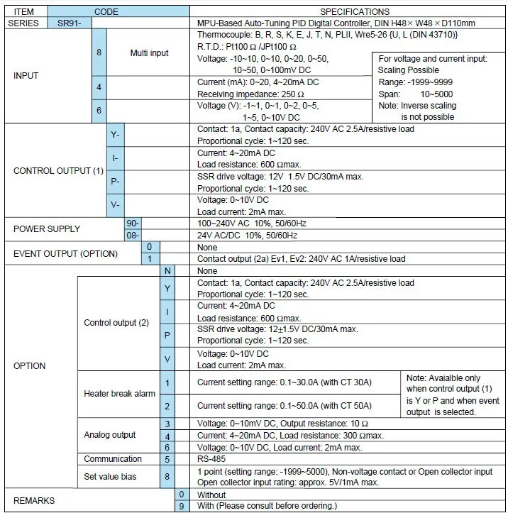
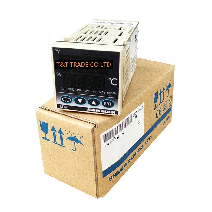
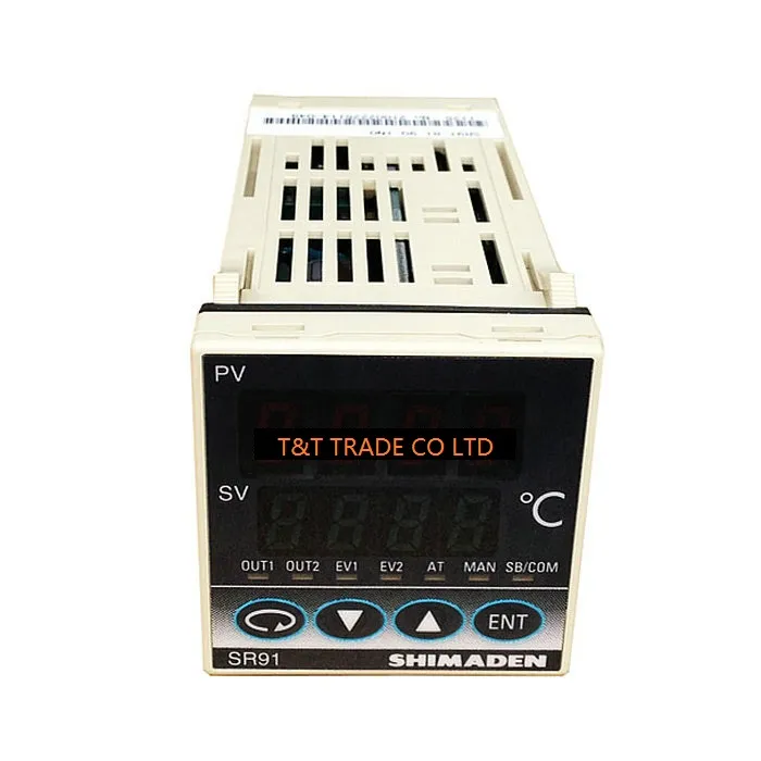
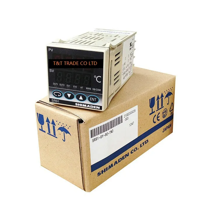
******************************************************************************

Удовлетворенность клиентов
Пожалуйста, не стесняйтесь обращаться к нам, если у вас есть какие-либо вопросы или проблемы до или после покупки. Мы стремимся к вашему 100% удовлетворению.
ОПЛАТА
На DHgate.com доступно множество способов оплаты, таких как кредитные карты, банковские переводы в режиме реального времени, автономные платежи (банковские переводы и Western Union). Вы можете выбрать метод, который является наиболее удобным для вас. Чтобы защитить ваши интересы, ваш платеж будет временно удерживаться DHgate и не будет передан нам до тех пор, пока вы не получите свой заказ и не будете удовлетворены им.
ПЕРЕВОЗКА
1. Стоимость доставки: нажмите вкладку «Доставка и оплата» на странице сведений о продукте, и вы увидите детали доставки. Вы можете рассчитать стоимость доставки, введя необходимую информацию.
2. Время в пути: время в пути зависит от способа доставки.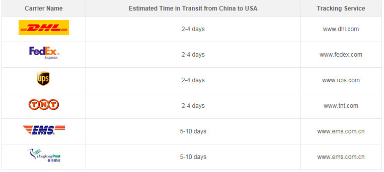
3. Время обработки товара: время обработки для конкретного заказа зависит от типа продукта и состояния склада В основном время обработки может составлять от 3 до 15 рабочих дней.
ПОЛИТИКА ВОЗВРАТА
Если вы хотите обменять полученные детали, вы должны связаться с нами в течение 3 дней с момента получения вашего заказа. И вы должны оплатить дополнительные транспортные расходы, а возвращенные товары должны быть сохранены в их первоначальном состоянии.
ОБРАТНАЯ СВЯЗЬ
Поскольку ваши отзывы очень важны для развития нашего бизнеса, мы искренне приглашаем вас оставить положительный отзыв для нас, если вы удовлетворены нашим продуктом и обслуживанием. Это займет у вас 1 минуту. Спасибо!