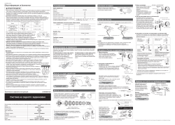
Manuals and User Guides for Shimano RD-M360.
We found 100
manuals for free downloads:
Dealer’s Manual, Service Instructions, User manual, User’s manual

Shimano WH-MT68-R12 Wheel Dealer’s Manual
Brand:
Shimano
Category:
Bicycles
Size:
4 MB
Pages:
182
Language(s):
English
Table of contents
-
7
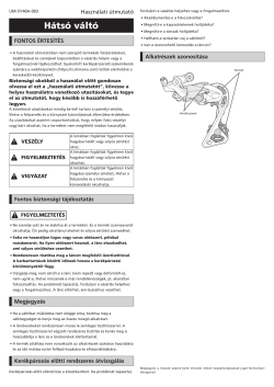
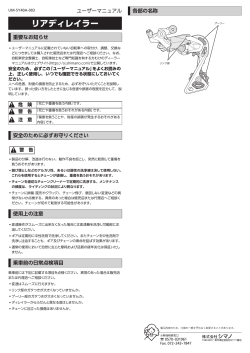
IMPORTANT NOTICE
-
8
TO ENSURE SAFETY
-
9
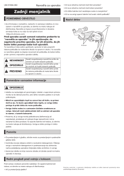
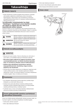
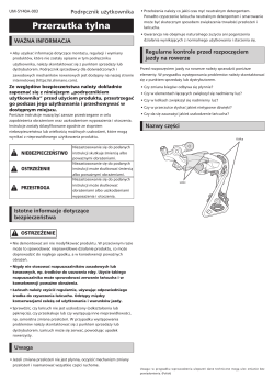
REAR DERAILLEUR
-
10
TO ENSURE SAFETY
-
12
REAR DERAILLEUR FOR MTB/TREKKING
-
12
Installation of the rear derailleur
-
14
Stroke adjustment
-
16
Securing the cable
-
21
SIS adjustment
-
23
Replacing the pulley
-
25
REAR DERAILLEUR FOR ROAD
-
25
Installation of the rear derailleur
-
27
Stroke adjustment
-
30
Securing the cable
-
32
SIS adjustment
-
34
Replacing the pulley
-
35
FRONT DERAILLEUR
-
36
TO ENSURE SAFETY
-
37
FRONT DERAILLEUR FOR MTB/TREKKING
-
37
Installation
-
43
Fixing the cable and adjusting the SIS (Front double)
-
49
Fixing the cable and adjusting the SIS (Front triple)
-
53
FRONT DERAILLEUR FOR ROAD
-
53
Installation
-
55
Fixing the cable and adjusting the SIS (Front double)
-
60
Fixing the cable and adjusting the SIS (Front triple)
-
66
MAINTENANCE
-
67
CHAIN
-
68
TO ENSURE SAFETY
-
71
CHAIN CONNECTING PIN
-
71
Method of use
-
72
QUICK-LINK
-
73
Installing a QUICK-LINK (SM-UG51)
-
75
Installing a QUICK-LINK (SM-CN900-11)
-
76
Removing a QUICK-LINK (SM-CN900-11)
-
77
BRAKE
-
78
TO ENSURE SAFETY
-
82
DISC BRAKE
-
82
Wheel spoke lacing
-
82
Installation of the disc brake rotor
-
87
INSTALLATION (HYDRAULIC DISC BRAKES)
-
87
Installation of the brake lever
-
89
Installation of the brake hose
-
93
Installation of the brake hose (easy hose joint system)
-
103
Replacing the brake hose (easy hose joint system)
-
107
Preventing loosening of frame fixing bolts
-
110
MAINTENANCE (HYDRAULIC DISC BRAKES)
-
110
Brake pad replacement
-
113
Adjustment when the pistons are not operating correctly
-
114
Lever stroke adjustment
-
114
Free stroke adjustment
-
115
Installation of the magnet holder
-
115
Mineral oil replacement
-
116
Adding mineral oil and bleeding air
-
121
INSTALLATION (V-BRAKE BRAKES)
-
121
Installation of the brake lever
-
121
Installing the power modulator
-
122
Installation of V-BRAKE brakes
-
125
MAINTENANCE (V-BRAKE BRAKES)
-
125
Replacement of the cartridge shoe
-
126
BRAKE LEVER WITH SWITCH INTERCHANGEABILITY (V-BRAKE AND HUB ROLLER BRAKES)
-
126
For V-BRAKE (with power modulator) mode
-
126
For Caliper brake/Roller brake
-
127
INSTALLATION (DUAL PIVOT CALIPER BRAKES)
-
130
Arch spring tension adjustment
-
131
MAINTENANCE (DUAL PIVOT CALIPER BRAKES)
-
131
Replacement of the cartridge shoe
-
132
SPECIFICATIONS (CANTILEVER BRAKES)
-
132
Cantilever brakes
-
132
Brake lever
-
133
INSTALLATION (CANTILEVER BRAKES)
-
133
Installation of the brake lever
-
134
Installation of the brake caliper
-
137
Installing SM-CB70
-
138
FRONT CHAINWHEEL
-
139
TO ENSURE SAFETY
-
141
INSTALLATION (CHAINRINGS)
-
141
For ROAD
-
142
For MTB/Trekking
-
143
INSTALLATION (FRONT CHAINWHEEL)
-
143
HOLLOWTECH II / 2 piece crankset
-
148
OCTALINK TYPE
-
149
SQUARE TYPE
-
151
INSTALLATION (PRESS-FIT BOTTOM BRACKET)
-
151
Adapter
-
151
Assembly example
-
152
Installation
-
153
Removal
-
154
PEDALS (SPD-SL PEDALS/SPD PEDALS)
-
155
TO ENSURE SAFETY
-
157
INSTALLATION (SPD PEDALS)
-
157
Engaging the cleats with the pedals
-
157
Releasing the cleats from the pedals
-
159
Attaching the cleats
-
161
Mounting the pedals on the crank arms
-
162
Adjusting the spring tension of the binding
-
162
Cleat replacement
-
163
INSTALLATION (SPD-SL PEDALS)
-
163
Cleat types
-
164
Engaging the cleats with the pedals
-
164
Releasing the cleats from the pedals
-
164
Attaching the cleats
-
165
Mounting the pedals on the crank arms
-
166
Adjusting the spring tension of the binding
-
166
Cleat replacement
-
167
Replacement of the body cover
-
167
Maintenance of the axle units
-
167
Mounting the reflectors (optional)
-
168
HUB DYNAMO
-
169
TO ENSURE SAFETY
-
171
INSTALLATION (HUB DYNAMO)
-
171
Installation of the disc brake rotor
-
171
Installation of the front wheel
-
175
CONNECTION OF THE CABLES
-
175
For E2 type
-
176
For J2 type
-
177
For J2-A type
-
179
Note on the connection of the cables
-
179
Checking the light illumination
-
180
MULTIPLE FREEWHEEL
-
181
INSTALLATION (MULTIPLE FREEWHEEL)
-
181
Installation of the freewheel
Open in a new tab


Shimano RD-TZ50 Dérailleur arrière Manuel utilisateur
Brand:
Shimano
Category:
Bicycle accessories
Size:
7 MB
Pages:
155
Language(s):
French
Table of contents
-
9
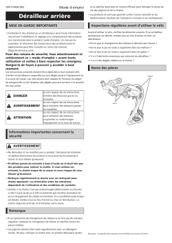
MISE EN GARDE IMPORTANTE
-
10
POUR VOTRE SÉCURITÉ
-
14
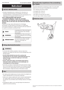
DÉRAILLEUR ARRIÈRE POUR VTT/TREKKING
-
14
Installation du dérailleur arrière
-
14
Type standard
-
14
Type à boîtier
-
15
Réglage de la course
-
15
Réglage supérieur
-
15
Réglage inférieur
-
16
Longueur de chaîne
-
17
Fixation du câble
-
17
Découpe de la gaine
-
18
Raccordement et fixation du câble
-
19
Utilisation de la vis B de réglage de tension
-
20
Réglage SIS
-
22
Remplacement de la poulie
-
22
Galet de guidage
-
22
Galet de tension
-
23
DÉRAILLEUR ARRIÈRE POUR ROUTE
-
23
Installation du dérailleur arrière
-
23
Type standard
-
24
Type à boîtier
-
24
Réglage de la course
-
24
Réglage supérieur
-
24
Réglage inférieur
-
24
Longueur de chaîne
-
27
Fixation du câble
-
27
Découpe de la gaine
-
27
Raccordement et fixation du câble
-
28
Utilisation de la vis B de réglage de tension
-
28
Réglage SIS
-
29
Remplacement de la poulie
-
31
POUR VOTRE SÉCURITÉ
-
32
DÉRAILLEUR AVANT POUR VTT/TREKKING
-
32
Installation
-
32
Type à collier
-
34
Type E
-
35
Type E (modèles sans plaque de boîtier de pédalier)
-
36
Type à montage direct
-
37
Fixation du câble et réglage du SIS (double avant)
-
37
Réglage inférieur
-
38
Fixation du câble
-
41
Réglage de la tension du câble
-
42
Réglage supérieur
-
42
Tableau de recherche des pannes
-
43
Fixation du câble et réglage du SIS (triple avant)
-
43
Réglage inférieur
-
43
Fixation du câble
-
44
Réglage supérieur
-
44
Réglage de la tension du câble
-
45
Tableau de recherche des pannes
-
46
DÉRAILLEUR AVANT POUR ROUTE
-
46
Installation
-
47
Fixation du câble et réglage du SIS (double avant)
-
47
Fonctionnement du levier et point d’indice de câble
-
48
Fixation du câble
-
49
Réglage inférieur
-
49
Réglage de la tension du câble
-
50
Réglage supérieur
-
51
Tableau de recherche des pannes
-
51
Fixation du câble et réglage du SIS (triple avant)
-
51
Fonctionnement du levier et point d’indice de câble
-
52
Réglage inférieur
-
53
Fixation du câble
-
53
Réglage supérieur
-
54
Réglage de la tension du câble
-
55
Tableau de recherche des pannes
-
56
ENTRETIEN
-
56
Type brasé
-
56
Type à collier
-
56
Type E
-
56
Type à montage direct
-
58
POUR VOTRE SÉCURITÉ
-
61
BROCHE DE RACCORDEMENT DE CHAÎNE
-
61
Méthode
-
62
QUICK-LINK
-
63
Installer un QUICK-LINK (SM-UG51)
-
64
Installer un QUICK-LINK (SM-CN900-11)
-
64
Retrait d’un QUICK-LINK (SM-CN900-11)
-
66
POUR VOTRE SÉCURITÉ
-
70
FREIN A DISQUE
-
70
Croisement des rayons
-
70
Installation du disque de frein à disque
-
70
Type à verrouillage central
-
72
Type à 5 boulons (avec rondelles-frein)
-
73
Type à 6 boulons
-
73
Type à 6 boulons (avec rondelles-frein)
-
74
INSTALLATION (FREINS A DISQUES HYDRAULIQUES)
-
74
Montage du levier de frein
-
75
Installation de la durite de frein
-
78
À l’extrémité de l’étrier (type Banjo)
-
78
À l’extrémité de l’étrier (type droit)
-
79
Installation de la durite de frein (système de raccord facile de la durite de frein)
-
79
Aperçu du système de raccord facile de la durite de frein (pour VTT)
-
81
Aperçu du système de raccord facile de la durite de frein (pour vélo ROUTE)
-
83
Coupe de la durite
-
85
Remplacement de la durite de frein (système de raccord facile de la durite de frein)
-
85
Pour les VTT BH
-
86
Pour les vélos ROUTE
-
87
Installation des étriers et fixation du flexible
-
88
Type de montage standard International
-
89
Système Postmount
-
90
Prévention du desserrage des boulons de fixation du cadre
-
90
Méthode du bouchon
-
90
Méthode du câble
-
91
Fixation du câble
-
92
ENTRETIEN (FREINS A DISQUES HYDRAULIQUES)
-
92
Remplacement des plaquettes de frein
-
94
Réglage en cas de dysfonctionnement des pistons
-
94
Réglage de la course du levier
-
95
Réglage d’attaque
-
95
Installation du support de l’aimant
-
95
Remplacement d’huile minérale
-
95
Rajouter de l’huile minérale et purger l’air
-
100
INSTALLATION (FREINS V-BRAKE)
-
100
Montage du levier de frein
-
100
Installation du modulateur de puissance
-
101
Installation des freins V-BRAKE
-
104
ENTRETIEN (FREINS V-BRAKE)
-
104
Remplacement des patins à cartouche
-
105
(FREINS V-BRAKE ET À TAMBOUR)
-
105
Mode pour V-BRAKE (avec modulateur)
-
105
Pour frein à étrier/frein à tambour
-
106
INSTALLATION (ÉTRIER DE FREIN À DOUBLE PIVOT)
-
108
Réglage de la tension du ressort de l’arc
-
109
ENTRETIEN (ÉTRIER DE FREIN À DOUBLE PIVOT)
-
109
Remplacement du patin à cartouche
-
111
SPÉCIFICATIONS (FREINS CANTILEVER)
-
111
Frein cantilever
-
111
Levier de frein
-
112
INSTALLATION (FREINS CANTILEVER)
-
112
Montage du levier de frein
-
112
Installation de l’étrier de frein
-
115
Installation du SM-CB
-
115
Méthode de réglage
-
117
POUR VOTRE SÉCURITÉ
-
119
INSTALLATION (PLATEAUX)
-
119
Pour les vélos ROUTE
-
119
Double plateau
-
120
Triple plateau
-
120
Pour les VTT / Trekking
-
120
Triple plateau
-
121
INSTALLATION (PLATEAU AVANT)
-
121
HOLLOWTECH II / Pédalier en 2 parties
-
121
Installation du pédalier
-
123
Disposition des entretoises (pour VTT/Trekking)
-
125
TYPE OCTALINK
-
125
Installation du boîtier de pédalier
-
125
Montage du pédalier
-
126
TYPE SQUARE
-
126
Installation du boîtier de pédalier
-
126
Montage du pédalier
-
127
INSTALLATION (BOÎTIER DE PÉDALIER PRESS-FIT)
-
127
Adaptateur
-
127
Exemple de montage
-
128
Installation
-
128
Démontage
-
131
POUR VOTRE SÉCURITÉ
-
133
INSTALLATION (PÉDALES SPD)
-
133
Enclenchement des cales sur les pédales
-
133
Déclencher les cales
-
133
Cales à déclenchement unidirectionnel : SM-SH51 (noir)
-
134
Cales à déclenchement multidirectionnel : SM-SH56 (argent, or)
-
134
Fixation des cales
-
135
Réglage de la position de la cale
-
136
Joint étanche
-
136
Montage des pédales sur les manivelles
-
137
Réglage de la tension de ressort de la fixation
-
137
Remplacement d’une cale
-
138
INSTALLATION (PÉDALES SPD-SL)
-
138
Types de cale
-
139
Enclenchement des cales sur les pédales
-
139
Déclencher les cales
-
139
Fixation des cales
-
140
Réglage de la position de la cale
-
140
Fixation des pédales sur les manivelles
-
141
Réglage de la tension de ressort de la fixation
-
141
Remplacement d’une cale
-
141
Remplacement du cache de corps
-
141
Entretien des unités d’axe
-
141
Fixation des réflecteurs (en option)
-
143
POUR VOTRE SÉCURITÉ
-
145
INSTALLATION (MOYEU-DYNAMO)
-
145
Installation du disque de frein à disque
-
145
Installation de la roue avant
-
145
Pour type à blocage rapide
-
146
Pour type à écrous
-
147
Pour le type E-THRU
-
148
RACCORDEMENT DES CÂBLES
-
148
Pour type E
-
149
Pour type J
-
150
Pour type J2-A
-
151
Remarque concernant la branchement des câbles
-
152
Vérification de l’éclairage
-
154
INSTALLATION (ROUE LIBRE MULTIVITESSE)
-
154
Montage de la roue-libre
Open in a new tab


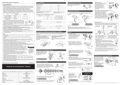


SI-6UAFA-003-00
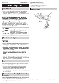
General Safety Information
WARNING
«Maintenance interval depends on the usage and riding circumstances. Clean regularly the chain with an
appropriate chaincleaner. Never use alkali based or acid based solvents such as rust cleaners. If those
solvent be used chain might break and cause serious injury.»
• Use the reinforced connecting pin only for connecting the narrow type of chain.
• There are two different types of reinforced connecting pins available. Be sure to check the table below before selecting which pin to use. If
connecting pins other than reinforced connecting pins
are used, or if a reinforced connecting pin or tool which
Chain
is not suitable for the type of chain is used, sufficient
9-speed super narrow chain
connection force may not be obtained, which could
such as
cause the chain to break or fall off.
CN-7701 / CN-HG93
8- / 7- / 6-speed narrow chain
such as
CN-HG50 / CN-HG40
• If it is necessary to adjust the length of the chain due to a change in the number of sprocket teeth, make the
cut at some other place than the place where the chain has been joined using a reinforced connecting pin or
an end pin. The chain will be damaged if it is cut at a place where it has been joined with a reinforced
connecting pin or an end pin.
• Be careful not to let the cuffs of your clothes get caught in the chain while riding, otherwise you may fall off
the bicycle.
• Check that the tension of the chain is correct and that the chain is not damaged. If the tension is too weak or the chain is damaged, the chain
should be replaced. If this is not done, the chain may break and cause serious injury.
• It is important to periodically check the tightening torques for the crank arms and pedals. After riding approximately 100 km (60 miles), re-
check the tightening torques. If the tightening torques are too weak, the crank arms or pedals may come off and the bicycle may fall over, and
serious injury may occur as a result.
• Check that there are no cracks in the crank arms before riding the bicycle. If there are any cracks, the crank arm may break and you may fall
off the bicycle.
• Obtain and read the service instructions carefully prior to installing the parts. Loose, worn or damaged parts may cause the bicycle to fall
over and serious injury may occur as a result. We strongly recommend only using genuine Shimano replacement parts.
• Obtain and read the service instructions carefully prior to installing the parts. If adjustments are not carried out correctly, the chain may
come off and this may cause you to fall off the bicycle which could result in serious injury.
• Read these Technical Service Instructions carefully, and keep them in a safe place for later reference.
CAUTION
• If the chain is on the smallest or intermediate chainring, there is the danger of injury from the tips of the teeth on the largest chainring.
Note
• In addition, if pedaling performance does not feel normal, check this once more.
• Before riding the bicycle, check that there is no play or looseness in the connection. Also, be sure to retighten the crank arms and pedals at
periodic intervals.
• When installing the pedals, apply a small amount of grease to the threads to prevent the pedals from sticking. Use a torque wrench to
securely tighten the pedals. Tightening torque: 35 — 55 N·m {305 — 479 in. lbs.}. The right-hand crank arm has a right-hand thread, and the left-
hand crank arm has a left-hand thread.
• Do not wash the bottom bracket with high-pressure jets of water.
• If you feel any looseness in the bottom bracket axle, the bottom bracket should be replaced.
• If gear shifting operations do not feel smooth, wash the derailleur and lubricate all moving parts.
• If the amount of looseness in the links is so great that adjustment is not possible, you should replace the derailleur.
• You should periodically wash the chainrings in a neutral detergent and then lubricate them again. In addition, cleaning the chain with neutral
detergent and lubricating it can be a effective way of extending the useful life of the chainrings and the chain.
• The cuffs of your clothing may get dirty from the chain while riding.
• If the chain keeps coming off the chainrings during use, replace the chainrings and the chain.
• When the chain is in the position shown in the illustration, the chain may contact the front chainrings
or front derailleur and generate noise. If the noise is a problem, shift the chain onto the next-larger rear
sprocket or the one after.
• Apply grease to the bottom bracket before installing it.
• For smooth operation, use the specified outer casing and the bottom bracket cable guide.
• This front derailleur is for triple front chainwheel use only. It cannot be used with the double front
chainwheel, as the shifting points do not match.
• When installing the top route type, choose a frame that has three outer casing holders as shown in the
illustration at right.
• Use an outer casing which still has some length to spare even when the handlebars are turned all the way to both
sides. Furthermore, check that the shifting lever does not touch the bicycle frame when the handlebars are turned all
the way.
• Grease the inner cable and the inside of the outer casing before use to ensure that they slide properly.
• Operation of the levers related to gear shifting should be made only when the front chainwheel is turning.
• Parts are not guaranteed against natural wear or deterioration resulting from normal use.
• For maximum performance we highly recommend Shimano lubricants and maintenance products
• For any questions regarding methods of installation, adjustment, maintenance or operation, please contact a professional bicycle dealer.
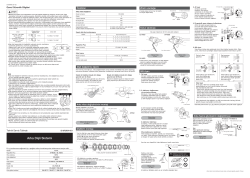
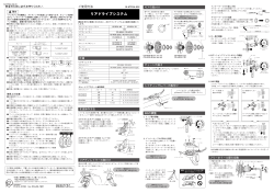
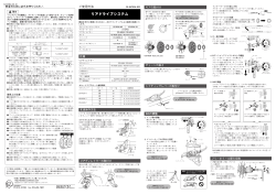
Technical Service Instructions
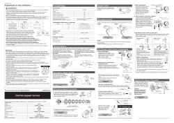
Front Drive System
In order to realize the best performance, we recommend that the following combination be used.
Right
SIS 9-gears
Gears
Left
SIS 3-gears
Shifting lever
ST-M390 / SL-M390 / ST-EF65
Outer casing
Front derailleur
FD-M390
Front chainwheel
FC-M391 / FC-M391-8
Bottom bracket
BB-UN26 (-K) / BB-ES25 (-K)
Chain
CN-HG53
Bottom bracket cable guide
SM-SP18 / SM-BT18 / SM-SP17 / SM-BT17
This service instruction explains how to use and maintain the Shimano bicycle parts which have been used on your new bicycle.
For any questions regarding your bicycle or other matters which are not related to Shimano parts, please contact the place of purchase or the
bicycle manufacturer.
One Holland, Irvine, California 92618, U.S.A. Phone: +1-949-951-5003
Industrieweg 24, 8071 CT Nunspeet, The Netherlands Phone: +31-341-272222
* Service Instructions in further languages are available at : http://techdocs.shimano.com
Please note: specifications are subject to change for improvement without notice. (English) © May 2011 by Shimano Inc. XBC IZM Printed in Singapore.
Specifications
Front Derailleur
Model number
Applicable to both normal type and top route type
TOP SWING
Applicable front chainwheel
Top gear tooth
Reinforced
Chain tool
connecting pin
Front chainwheel tooth difference
Min. difference between top and intermediate
Silver
TL-CN32 / TL-CN27
Front derailleur installation band diameter
6.5mm
a
Chainstay angle (
)
Black
TL-CN32 / TL-CN27
Applicable bottom bracket
7.1mm
Applicable chain line
Reinforced Connecting Pin
Installation band diameters: S [28.6 mm], M [31.8 mm], L [34.9 mm] (Use the adapter for S and M sizes.)
Chainwheel
End Pin
Link Pin
Model number
Chainwheel tooth combination
Bolt circle diameter
Crank arm length
Pedal thread dimensions
Applicable bottom bracket
Bottom Bracket
Model number
Stamped marking
Spindle length
Chain line
Thread dimensions
*
t = Chain case thickness (1.5 — 2.1 mm)
Gear shifting operation
Both lever (A) and lever (B) always return to the initial position when they are released after shifting.
When operating one of the levers, always be sure to turn the crank arm at the same time.
To shift from a small chainring to a larger chainring
(Lever A)
When lever (A) is pressed once, there is a shift of one step
from a small chainring to a larger chainring.
Front
Example:
chainrings
from intermediate
chainring to largest
chainring.
Rear
sprockets
Outer casing holders
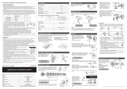
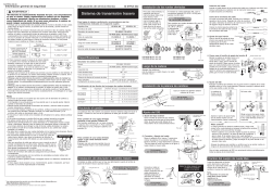
Installation of the Front Derailleur, Bottom Bracket and Front Chainwheel
Use the special tools (TL-UN66 and TL-UN74-S) to install the
bottom bracket 1 and the front derailleur so that they face as
shown in the illustration. Install the adapter 2, and then use
the cotterless crank extractor (TL-FC10) to install the front
chainwheel.
SI-6UAFA-003
Front Derailleur
2 Adapter
1 Bottom Bracket
SIS 8 / 7-gears
SIS 3-gears
Adapter / bottom bracket tightening torque:
50 — 70 N·m {435 — 608 in. lbs.}
ST-EF65
Front chainwheel tightening torque:
OT-SP40
35 — 50 N·m {305 — 435 in. lbs.}
FD-M360 / M311 / M190A / M190 / M191
FC-M311 / FC-M311-8 / FC-M171 / FC-M131
CN-HG50 / CN-HG40
Chain length
Add 2 links (with the chain on
both the largest sprocket and
the largest chainring)
3-77 Oimatsu-cho, Sakai-ku, Sakai-shi, Osaka 590-8577, Japan
FD-M390
FD-M360
FD-M311
FD-M190A
FD-M190
X
X
X
X
X
X
–
X
FC-M391 / M391-8
FC-M311 / FC-M311-8
FC-M171 / M131
44 / 48T
42 / 48T
42 / 48T
42T
22T
20T
20T
18T
12T
10T
10T
8T
S, M, L
63°- 66° / 66°- 69°
66°- 69°
63°- 66°
BB-UN26 (-K) / BB-ES25 (-K)
50 mm
47.5 / 50 mm
FC-M391
FC-M391-8
FC-M311
FC-M311-8
FC-M171
44-32-22T / 48-36-26T
42-32-22T / 48-38-28T
42-32-22T
42-34-24T / 48-38-28T
104 / 64 mm
—
170 / 175 mm
170 / 175 mm
BC 9/16″ X 20 T.P.I. (English thread)
BB-UN26 (-K)
BB-ES25 (-K)
BB-UN26 (-K)
BB-ES25 (-K)
BB-UN26 (-K)
BB-ES25 (-K)
LL123
D-NL K
D-NL
126 (-K)
122.5 mm
126 mm
50 mm
47.5 mm + t*
47.5 mm
50 mm
BC 1.37″ X 24 T.P.I. (68, 73 mm)
To shift from a large chainring to a smaller chainring
(Lever B)
When lever (B) is pressed once, there is a shift of one step
from a large chainring to a smaller chainring.
Example:
Lever (A) initial position
from largest chainring to
intermediate chainring.
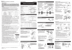
Adjust and then install the front derailleur as shown in the
illustration. Do not remove the Pro-Set alignment block at this
time.
Pro-Set alignment block
Gear teeth
should come
within this range
3 Front Chainwheel
Pro-Set gauge
1 mm
3 mm
8 mm Allen key
(FC-M391 / FC-M391-8)
The level section of the chain
guide outer plate should be
directly above and parallel to the
largest chainring. Secure using a
5 mm Allen key.
Tightening torque :
5 — 7 N·m {44 — 60 in. lbs.}
Installation of the lever
Use a handlebar grip with a maximum outer diameter of
Largest sprocket
Largest chainring
36 mm (M390) / 32 mm (EF65).
ST-M390 / ST-EF65
Chain
6 — 8 N·m {53 — 69 in. lbs.}
5 mm Allen key
SL-M390
X = Available
Tightening torque :
5 N·m {44 in. lbs.}
FD-M191
X
X
X
X
5 mm Allen key
• Install the shifting lever in a position where it will not obstruct brake
operation and gear shifting operation.
42T
48T
• Do not use in a combination which causes brake operation to be
18T
20T
obstructed.
8T
10T
63°- 66° / 66°- 69°
SIS adjustment
Chainstay angle
Be sure to follow the sequence described below.
1. Low adjustment
First remove the Pro-Set alignment block.
FC-M131
Next, set so that the clearance between the chain guide inner plate
and the chain is 0-0.5 mm.
—
FD-M311
170 / 175 mm
BB-UN26 (-K)
Low adjustment
Pro-Set alignment block
Chain position
Chain guide
inner plate
Smallest
Largest sprocket
chainring
Chain
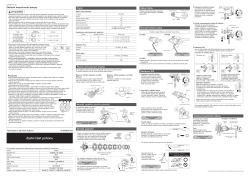
2. Connecting and securing the inner cable
<ST-M390 / SL-M390>
Operate lever (B) two times or
Lever (B)
more, and check on the indicator
that the lever is at the lowest
position. Then remove the inner
hole cover and connect the inner
cable.
Inner hole cover
Inner cable
Install the inner hole cover by turning it as
shown in the illustration until it stops.
Do not turn it any further than this,
otherwise it may damage the screw
thread.
Inner hole cover
Lever (B)
<ST-EF65>
Operate lever (B) two times or more to set the lever to the lowest
position. Remove the screw, and then remove the cover. Pull out the
inner cable as shown in Figure, and then install the new inner
cable.
Screw
Cover
Lever (B)
Inner cable
Tightening torque:
0.3 — 0.5 N·m {3 — 4 in. lbs.}
Chainwheel
(largest chainring)
Chain guide
Inserting the inner cable
Insert the inner cable into the outer casing from the end with the
marking on it. Apply grease from the end with the marking in order
to maintain cable operating
efficiency.
Marking
Cutting the outer casing
When cutting the outer casing, cut the opposite end to the end with
the marking. After cutting the outer casing, make the end round so
that the inside of the hole has a uniform
diameter.
Attach the same outer end cap to the cut end of the outer casing.
Tightening torque:
Outer end cap
Use a 5 mm Allen key to tighten the wire fixing bolt.
Cut off the excess length of inner cable and then install the
inner end cap.
< FD-M390 / M360 / M190A / M190 / M191 >
< FD-M311 >
Note:
Pass the cable through as
shown in the illustration.
Tightening torque :
5 — 7 N·m
{44 — 60 in. lbs.}
M390/M190A/M190
M360/M191
M311
After taking up the initial slack in the cable, re-secure to the
front derailleur as shown in the illustration.
Normal type
Top route type
Pull
Pull
screw
FD-M390
FD-M360
FD-M190A
FD-M190
3. Top adjustment
FD-M191
Set so that the clearance between the chain guide outer
plate and the chain is 0-0.5 mm.
FD-M311
Chain position
Smallest sprocket
Largest chainring
Top adjustment
FD-M390
screw
FD-M360
Chain guide outer
FD-M190A
plate
FD-M190
FD-M191
Chain
4. Adjustment of the intermediate chainring
When carrying out adjustment, set the chain to the largest
sprocket, and at the front, set the chain to the intermediate
chainring. Adjust using the outer casing adjustment barrel
so that the clearance between the chain guide inner plate
and the chain is 0-0.5 mm.
Chain position
Intermediate
Largest sprocket
chainring
A
B
B
Chain guide
inner plate
A
Chain
Outer casing adjustment barrel
5. Troubleshooting chart
After completion of steps 1 — 4, move the shifting lever to
check the shifting. (This also applies if shifting becomes
difficult during use.)difficult during use.)
If the chain falls to the crank
Tighten the top adjustment
side.
screw clockwise (about 1/4
turn).
If shifting is difficult from the
Loosen the top adjustment
intermediate chainring to the
screw counterclockwise
largest chainring.
(about 1/8 turn).
If shifting is difficult from the
Loosen the low adjustment
intermediate chainring to the
screw counterclockwise
smallest chainring.
(about 1/4 turn).
If there is interference between
Tighten the top adjustment
the chain and the front derailleur
screw clockwise (about 1/8
inner plate at the largest
turn).
chainring.
If there is interference between
Loosen the top adjustment
screw counterclockwise
the chain and the front derailleur
outer plate at the largest
(about 1/8 turn).
chainring.
If the intermediate chainring is
Loosen the outer casing
skipped when shifting from the
adjustment barrel
largest chainring.
counterclockwise (1 or 2
turns).
If there is interference between
Tighten the outer casing
the chain and front derailleur
adjustment barrel clockwise
inner plate when the rear
(1 or 2 turns).
sprocket is shifted to the largest
sprocket when the chainwheel is
at the intermediate chainring
position.
If the chain falls to the bottom
Tighten the low adjustment
bracket side.
screw clockwise (about 1/2
turn).
If the lever is stiff when shifting
Loosen the top adjustment
from the intermediate chainring
screw counterclockwise (about
1/4 turn).
to the largest chainring
На чтение 5 мин Просмотров 3.6к.
Содержание
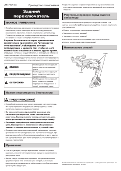
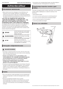
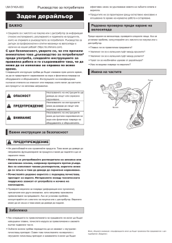
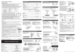
- Переключатель задний Shimano RD-M360 – описание
- Технические характеристики
- Отзывы велосипедистов
- Установка и регулировка заднего переключателя скоростей
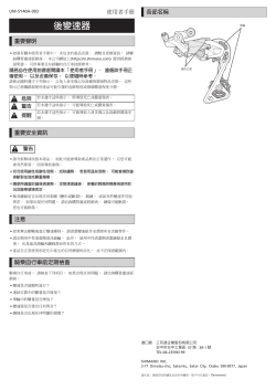
На горных велосипедах часто проводится установка переключатель скорости. Его предназначение заключается в изменении передаточного отношения за счет перекидывания цепи на другую звездочку.

Конструкция переключателя довольно сложная, низкокачественное изделие не сможет прослужить в течение длительного периода.
Shimano RD М360 – довольно распространенное оборудование, которое устанавливается на качественных горных велосипедах. Конструкция характеризуется большим количеством особенностей, о которых далее поговорим подробнее.
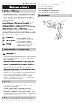
Переключатель задний Shimano RD-M360 – описание

Переключатель скоростей представлен наружным навесным оборудованием, которое отвечает за перебрасывание цепи на звездочки и обеспечение требуемого уровня натяжения.
Механизм выглядит следующим образом:
- Корпус состоит из двух элементов, которые находятся относительно друг друга под углом. Пружина позволяет проводить плавное переключение скорости.
- Основной элемент представлен звездочкой, за счет которой обеспечивается натяжение цены.
- Основная часть изготавливается из металла. За счет этого обеспечивается длительный эксплуатационный срок.
Конструкция довольно сложная, при этом провести ремонт своими руками практически невозможно. Поверхность металла покрывается краской для обеспечения повышенной защиты.
Технические характеристики

При выборе переключателя скоростей следует уделить внимание основным параметрам.
Они выглядят следующим образом:
- Основная часть окрашивается в серый цвет. При этом внутренние элементы механизма черные.
- Увеличенный ролик натяжения рассчитан на 13 зубьев, есть и натяжной, за счет чего снижается уровень шума и износа. Именно поэтому при движении не возникает сильного шума или треска. Подобный признак указывает на то, что механизм низкокачественный.
- Пружина рассматриваемого механизма работает на растяжение и обеспечивает низкий коэффициент трения при переключении скорости.
- При изготовлении пружины возврата для высокой передачи применяется манетка Rapidfire. Она характеризуется достаточно высокой надежностью в применении.
- Рекомендуемые цепи IGи HG. Они совместимы с системами, у которых 7 и 8 скоростей.
Приведенные выше параметры следует учитывать при выборе подходящего устройства переключения скоростей.
Отзывы велосипедистов
Рассматриваемый переключатель скорости установлен на велосипеде, которые обошелся мне в 40 000 рублей. Через 200 км пройденного пути нужно было провести натяжение тросика.
При быстром и агрессивном спуске было падение с сальто, после чего конструкция не изменила свои эксплуатационные характеристики. Сброс цепи мягкий и бесшумный, натяжение сильное. Еще был один сильный удар о бордюр, через некоторое время пружина восстановилась.
Оценка:
Олег
Этот переключатель соответствует своей ценовой категории, работает хорошо, проблем не возникало. Выглядит довольно привлекательно.
Оценка:
Антон
Читал довольно много положительных отзывов, но у меня прослужил не долго. Используемый направляющий ролик без подшипника, даже железной сердцевины нет, поэтому конструкция быстро развалилась.
Оценка:
Дмитрий
Как у кого, у меня ролик прослужил не более 2-х месяцев. Сначала думал, что дело в моем стиле катания, но потом поставил другой вариант натяжения, служит он долго.
Оценка:
Алексей
Служит этот переключатель у меня около 5 тысяч километров. Служит устройство достаточно хорошо, в год 3-4 раза снимал для обслуживания. Для меня отличный вариант.
Оценка:
Евгений
Установка и регулировка заднего переключателя скоростей

Провести установку и регулировку переключателя скорости можно самостоятельно.
Инструкция монтажа выглядит следующим образом:
- Работа начинается со снятия старого нонейма. В большинстве случаев происходит раскрывание цепи, при его отсутствии потребуется специальный выжимной механизм.
- Следующий шаг заключается в снятии старого устройства, после чего проводится крепление нового. На момент прикручивания нужно использовать специальный ключ, так как слишком большое усилие может стать причиной срыва резьбы.
- Далее проводится установка цепи на самую малу звездочку. На момент накидывания цепи нужно следить за тем, чтобы обе звездочки были на одной линии, так как в противном случае цепь будет соскакивать.
- Маленькая звездочка предназначена для высокой скорости. Именно поэтому регулировка проводится при помощи винта H.
- При проведении настройки регулировочного элемента следят за тем, чтобы цепь не попадала в спицы. Для этого переключатель отводится до самой большой звезды. Запрещается отодвигать его за ролик, так как крепление может быть повреждено.
- Фиксация устройства осуществляется за счет регулировочного винта. При слишком сильном зажатии переключателя нижней передачи не будет.
- При фиксации тросика следует уделить внимание тому, чтобы он свободно ходил в рубашке. На момент установки проверяется ход и факт отсутствия залома. Нужно провести установку цепи снова на маленькую звездочку, после чего трос подтягивается. На момент натяжения тросика нужно уделять внимание тому, что он может при воздействии высокого усилия просто лопнуть.
После проведения подобной работы нужно проверить механизм. На момент кручения педалей никаких тресков не должно появляться, переключение проводится точно без задержек и перекоса. Даже при отсутствии дефекта следует в первую поездку с собой взять отвертку, так как есть вероятность, что нужно будет проводить настройку повторно.
Задний переключатель скоростей Shimano RD-M360 достаточно качественный и подходит для многих велосипедов. Однако некоторые отзывы указывают на то, что механизм может прослужить в течение короткого промежутка времени.
 
|
||
| Страница 1 из 1 [ Сообщений: 7 ] |
| Автор | Сообщение |
|---|---|
|
Заголовок сообщения: Настройка заднего переключателя Shimano RD-M360 Acera
|
|
|
|
Добрый день, уважаемые сообщники! Велосипедист я начинающий, веломастер ещё тот, хотя руки, вроде, из правильного места. Но не могу настроить упомянутый переключатель — хоть плачь. Симптомы такие — снизу вверх переключает четко, без проблем. Сверху вниз — с восьмой звезды на седьмую два клика вместо одного, потом с шестой на пятую — перескок через звезду, т.е. на четвертую. Тросик поменял, боудены поменял, только рубашки не поменял, пружины промыл и смазал. Осталось кассету и цепь поменять, а там и сам переключатель. Подскажите, в чем может быть, на самом деле, проблема? Вел прошёл 1500 км. _________________ |
| Вернуться к началу |
P |


|
denon480 |
Заголовок сообщения: Re: Настройка заднего переключателя Shimano RD-M360 Acera
|
|
|
Vld_Sergio писал(а): Добрый день, уважаемые сообщники! Велосипедист я начинающий, веломастер ещё тот, хотя руки, вроде, из правильного места. Но не могу настроить упомянутый переключатель — хоть плачь. Симптомы такие — снизу вверх переключает четко, без проблем. Сверху вниз — с восьмой звезды на седьмую два клика вместо одного, потом с шестой на пятую — перескок через звезду, т.е. на четвертую. Тросик поменял, боудены поменял, только рубашки не поменял, пружины промыл и смазал. Осталось кассету и цепь поменять, а там и сам переключатель. Подскажите, в чем может быть, на самом деле, проблема? Вел прошёл 1500 км. Возможно поможет, но это уже крайности. Последний раз редактировалось denon480 25.08.2015 11:02, всего редактировалось 2 раз(а). |
| Вернуться к началу | |

|
sashagoncharov |
Заголовок сообщения: Re: Настройка заднего переключателя Shimano RD-M360 Acera
|
|
|
Vld_Sergio писал(а): Добрый день, уважаемые сообщники! Велосипедист я начинающий, веломастер ещё тот, хотя руки, вроде, из правильного места. Но не могу настроить упомянутый переключатель — хоть плачь. Симптомы такие — снизу вверх переключает четко, без проблем. Сверху вниз — с восьмой звезды на седьмую два клика вместо одного, потом с шестой на пятую — перескок через звезду, т.е. на четвертую. Тросик поменял, боудены поменял, только рубашки не поменял, пружины промыл и смазал. Осталось кассету и цепь поменять, а там и сам переключатель. Подскажите, в чем может быть, на самом деле, проблема? Вел прошёл 1500 км. мне кажется дешевле будет в какой-то вело магазинчик подъехать — там даже не самый опытный механик асеру настроить сможет нормально. а так вообще погнутый петух, супер-растянутая цепь или грязь внутри рубашек не дает сбрасывать в общем вариантов много _________________ |
| Вернуться к началу | |

|
Vld_Sergio |
Заголовок сообщения: Re: Настройка заднего переключателя Shimano RD-M360 Acera
|
|
|
sashagoncharov писал(а): мне кажется дешевле будет в какой-то вело магазинчик подъехать — там даже не самый опытный механик асеру настроить сможет нормально. а так вообще погнутый петух, супер-растянутая цепь или грязь внутри рубашек не дает сбрасывать в общем вариантов много Это-то само-собой. Но хотелось бы самому сначала натрахаться, а уж потом сдаваться. _________________ |
| Вернуться к началу | |
|
denon480 |
Заголовок сообщения: Re: Настройка заднего переключателя Shimano RD-M360 Acera
|
|
|
Vld_Sergio писал(а): sashagoncharov писал(а): мне кажется дешевле будет в какой-то вело магазинчик подъехать — там даже не самый опытный механик асеру настроить сможет нормально. а так вообще погнутый петух, супер-растянутая цепь или грязь внутри рубашек не дает сбрасывать в общем вариантов много Это-то само-собой. Но хотелось бы самому сначала натрахаться, а уж потом сдаваться. Тогда там же и правка петуха И кстати боуден это и есть рубашка. |
| Вернуться к началу | |

|
Chemodan |
Заголовок сообщения: Re: Настройка заднего переключателя Shimano RD-M360 Acera
|
|
|
Смени рубашки и чудо не заставит себя ждать) _________________ |
| Вернуться к началу | |

|
Vld_Sergio |
Заголовок сообщения: Re: Настройка заднего переключателя Shimano RD-M360 Acera
|
|
|
denon480 писал(а): И кстати боуден это и есть рубашка. А не только пластиковый наконечник на рубашке, который упирается в регулятор натяжения на переключателе и шифтере, а так же в упоры на раме? _________________ |
| Вернуться к началу | |