-
Contents
-
Table of Contents
-
Bookmarks
Quick Links
OPERATING INSTRUCTIONS
Dx35
DISTANCE SENSORS
Related Manuals for SICK D 35 Series
Summary of Contents for SICK D 35 Series
-
Page 1
OPERATING INSTRUCTIONS Dx35 DISTANCE SENSORS… -
Page 2
Germany Copyright This work is protected by copyright. The associated rights are reserved by SICK AG. Reproduction of this document or parts of this document is only permissible within the limits of the legal provisions of copyright law. Any modifica- tion, abridgment, or translation of this document is prohibited without the express written permission of SICK AG. -
Page 3: Table Of Contents
Aligning the DL and DR variants ……….23 Alignment aid for infrared models ……… 23 Electrical connection …………..25 Safety ………………25 Wiring instructions …………..25 Connecting the distance sensor electrically ……26 8014868/YIF1/2020-10-19 • © SICK AG • Subject to change without notice…
-
Page 4
Output as alarm output …………51 10.5 Centering function or center displacement ……52 10.6 Teach confirmation function ……….53 10.7 Device backward compatibility (DBC) ……..54 10.8 Timer function …………….. 54 © SICK AG • Subject to change without notice • 8014868/YIF1/2020-10-19… -
Page 5
Structural design …………..61 13.10 «Repeatability» diagrams …………61 13.10.1 DT35 and DS35 models ……… 61 13.10.2 DL35 and DR35 models……… 63 Accessories ………………64 15 Configuration overview …………..65 Index ………………….66 8014868/YIF1/2020-10-19 • © SICK AG • Subject to change without notice… -
Page 6
© SICK AG • Subject to change without notice • 8014868/YIF1/2020-10-19… -
Page 7: Important Safety Notes
Adapters including field wiring cables are available. → See “www.sick.com/Dx35” CAUTION! Using control elements or settings or executing proce- dures other than those specified in this document may result in dangerous exposure to radiation. 8014868/YIF1/2020-10-19 • © SICK AG • Subject to change without notice…
-
Page 8: General Information
These operating instructions do not provide information on operating the machine or system in which the device is integrated. For information about this, refer to the operating instructions of the specific machine. © SICK AG • Subject to change without notice • 8014868/YIF1/2020-10-19…
-
Page 9: Explanation Of Symbols
… indicates a possible hazardous situation which may lead to physical damage if it is not avoided. Tips and recommendations NOTE! … highlights useful tips and recommendations as well as information for efficient and trouble-free operation. 8014868/YIF1/2020-10-19 • © SICK AG • Subject to change without notice…
-
Page 10: Limitation Of Liability
Before calling, make a note of all type label data such as type code, serial number, etc., to ensure faster process- ing. EU declaration of conformity → You can download the EU declaration of conformity from “www.sick. com/Dx35”. © SICK AG • Subject to change without notice • 8014868/YIF1/2020-10-19…
-
Page 11: Environmental Protection
General information Environmental protection → See “Disposal”, Chapter 12 on page 55 8014868/YIF1/2020-10-19 • © SICK AG • Subject to change without notice…
-
Page 12: Safety
The DL35 and DR35 distance sensors are opto-electronic sensors for per- forming non-contact distance measurement on reflective tape. SICK AG assumes no liability for losses or damage arising from the use of the product, either directly or indirectly. This applies in particular to use of the product that does not conform to its intended purpose and is neither described nor mentioned in this documentation.
-
Page 13: Requirements For Skilled Persons And Operating Personnel
Laser Notice No. 50 except for deviations pursuant to laser notice dated 24/06/2007 No. 50, dated June 24, 2007 Fig. 1: Warning symbol on sensor with class 2 laser 8014868/YIF1/2020-10-19 • © SICK AG • Subject to change without notice…
-
Page 14: Operational Safety And Particular Hazards
Please observe the safety notes and the warnings listed here and in other chapters of these operating instructions to reduce the possibility of risks to health and avoid dangerous situations. © SICK AG • Subject to change without notice • 8014868/YIF1/2020-10-19…
-
Page 15: Hazard Warnings And Operational Safety
“Dx35 distance sensor” type label 1 2D code 2 For type description, see type code 3 Article number (order number) 4 Year and month of manufacture 5 Serial number 8014868/YIF1/2020-10-19 • © SICK AG • Subject to change without notice…
-
Page 16: Type Code
Analog current or voltage output (Q2), switching output (Q1) and IO-Link Measurement Optimized for natural objects Optimized for reflective tape Other info Additional characters possible Table 1: “Dx35 distance sensor” type code © SICK AG • Subject to change without notice • 8014868/YIF1/2020-10-19…
-
Page 17: Design And Function
Q1 and Q2 • «Q1» and «Q2» LEDs flash simultaneously: teach is being performed. in teach mode • «Q1» and «Q2» LEDs flash alternately for 5 seconds: teach failed. 8014868/YIF1/2020-10-19 • © SICK AG • Subject to change without notice…
-
Page 18
Alignment quality indicator (IR models only) Q2 near, Q2 far, • The greater the number of LEDs that light up, the better slow … fast the teach-in quality. in alignment mode © SICK AG • Subject to change without notice • 8014868/YIF1/2020-10-19… -
Page 19
10 seconds: Enter or leave expert mode. • In teach mode After previously performing teach, press select and set pushbuttons simultaneously for less than 1 second: Enter or leave fine teach. Table 5: Operating pushbuttons 8014868/YIF1/2020-10-19 • © SICK AG • Subject to change without notice… -
Page 20: Function
For the DT35 and DL35 models, the Q2 output can be configured as a cur- rent output (4 … 20 mA), voltage output (0 … 10 V), or switching output. © SICK AG • Subject to change without notice • 8014868/YIF1/2020-10-19…
-
Page 21: Transport And Storage
• File a complaint. NOTE! Complaints regarding defects should be filed as soon as these are detected. Damage claims are only valid before the applicable complaint deadlines. 8014868/YIF1/2020-10-19 • © SICK AG • Subject to change without notice…
-
Page 22: Storage
For storage periods of longer than 3 months, check the general condition of all components and packaging on a regular basis. NOTE! Other storage conditions may apply to special equip- ment. → See separate operating instructions for special equipment. © SICK AG • Subject to change without notice • 8014868/YIF1/2020-10-19…
-
Page 23: Mounting
5 seconds. 4. Perform coarse alignment. To do this, align the distance sensor roughly in the direction of the reflective tape. 8014868/YIF1/2020-10-19 • © SICK AG • Subject to change without notice…
-
Page 24
Q2 far slow fast select 15 Hz Q1 Q2 Q1 near ObSB Q1 far Q2 near ObSB Q2 far slow fast Fig. 7: Aligning infrared light models, entering alignment mode © SICK AG • Subject to change without notice • 8014868/YIF1/2020-10-19… -
Page 25: Electrical Connection
• Only connect and disconnect cable connections when the power is off. Wiring instructions IMPORTANT! Faults due to incorrect wiring! Incorrect wiring may result in operational faults. For this reason: • Follow the wiring instructions closely. 8014868/YIF1/2020-10-19 • © SICK AG • Subject to change without notice…
-
Page 26: Connecting The Distance Sensor Electrically
Analog output Qa/ switching output Q2 Blue Supply voltage: 0 V Q1/C Black Switching output Q1/ IO-Link Gray Multifunctional input MF Table 6: Description of M12 plug, DT35 and DL35 © SICK AG • Subject to change without notice • 8014868/YIF1/2020-10-19…
-
Page 27: Ds35 And Dr35
Output signal switching device Q2 Blue Supply voltage: 0 V Q1/C Black Switching output Q1 / IO-Link Gray Multifunctional input MF Table 7: Description of M12 plug, DS35 and DR35 8014868/YIF1/2020-10-19 • © SICK AG • Subject to change without notice…
-
Page 28: Commissioning
The correct output must be selected before performing the teach procedure. → See Chapter 8.5 on page 36 NOTE! The hysteresis is preset to 25 mm and can be adjusted only via IO-Link. © SICK AG • Subject to change without notice • 8014868/YIF1/2020-10-19…
-
Page 29: Performing One-Point Teach (Dto)
5 seconds or wait 5 minutes without pushing the pushbut- tons. Q1 far or Q2 far (inverted behavior) Fig. 11: One-point teach Q1 far or Q2 far (inverted behavior) 1 Teach point: switching point, position 1 8014868/YIF1/2020-10-19 • © SICK AG • Subject to change without notice…
-
Page 30: Performing Window Teach (Wnd)
LEDs Q1 and Q2 flash twice simultaneously. If the teach was not suc- cessful, the LEDs Q1 and Q2 flash alternately. 4. If necessary, perform fine teach. → See Chapter 8.3 on page 34 © SICK AG • Subject to change without notice • 8014868/YIF1/2020-10-19…
-
Page 31
8. If necessary, perform fine teach. → See Chapter 8.3 on page 34 9. In order to leave teach mode, either press the select pushbutton longer than 5 seconds or wait 5 minutes without pushing the pushbut- tons. 8014868/YIF1/2020-10-19 • © SICK AG • Subject to change without notice… -
Page 32: Teaching In The Background (Obsb)
5. If necessary, perform fine teach. → See Chapter 8.3 on page 34 6. In order to leave teach mode, either press the select pushbutton longer than 5 seconds or wait 5 minutes without pushing the pushbut- tons. © SICK AG • Subject to change without notice • 8014868/YIF1/2020-10-19…
-
Page 33: Scaling The Analog Output
2 Minimum span between the teach points of the distance near the sensor and the distance far from the sensor: 50 mm 3 Teach point for distance far from the sensor 8014868/YIF1/2020-10-19 • © SICK AG • Subject to change without notice…
-
Page 34: Performing Fine Teach
1. Perform teach. → See Chapter 8.1 on page 28 and Chapter 8.2 on page 33 2. Press the select and set pushbuttons simultaneously for less than 1 second. The LED of the teach point to be moved flashes. © SICK AG • Subject to change without notice • 8014868/YIF1/2020-10-19…
-
Page 35: Configuring The Speed
→ See Chapter 9.3.3 on page 43 4. In order to leave teach mode, either press the select pushbutton longer than 5 seconds or wait 5 minutes without pushing the pushbut- tons. 8014868/YIF1/2020-10-19 • © SICK AG • Subject to change without notice…
-
Page 36: Expert Mode
• LED slow … fast flashes 3 x: switching output. 4. In order to leave expert mode, press the select and set pushbuttons for longer than 10 seconds or wait 5 minutes without pushing the pushbuttons. © SICK AG • Subject to change without notice • 8014868/YIF1/2020-10-19…
-
Page 37: Resetting The Settings To The Factory Setting
Teach in Q2 distance to object 1000 Teach in inverted behavior Q2 distance to object 1100 Teach in Q2 near for window 1200 Teach in Q2 far for window 1300 8014868/YIF1/2020-10-19 • © SICK AG • Subject to change without notice…
-
Page 38
3) These parameters are valid only for DT and DL models. For DS and DR models, these teach functions would cause an error indication (Q1 and Q2 LEDs flashing alternately). 4) → For a description, see Chapter 10.6 on page 53 © SICK AG • Subject to change without notice • 8014868/YIF1/2020-10-19… -
Page 39: Io-Link Interface
Bit 15 Bit 14 Bit 13 Bit 12 Bit 11 Bit 10 Bit 9 Bit 8 Bit 7 Bit 6 Bit 5 Bit 4 Bit 3 Bit 2 Bit 1 Bit 0 Distance measured value (14-bit) 4), 5) 8014868/YIF1/2020-10-19 • © SICK AG • Subject to change without notice…
-
Page 40
6) Signal quality from 0 to 3. 0 = No signal or very weak signal; 1 = Sufficient; 2 = Good; 3 = Excellent 7) → See Chapter 10.7 on page 54 Table 12: Process data structure © SICK AG • Subject to change without notice • 8014868/YIF1/2020-10-19… -
Page 41: Service Data
Table 14: IO-Link-specific service data – other settings 9.3.2 SICK-specific – outputs NOTE! In the following tables, the factory settings are indicated in bold in the «Value range» and «Example» columns. 8014868/YIF1/2020-10-19 • © SICK AG • Subject to change without notice…
-
Page 42
50 … 50000 mm – In 1 mm steps displacement 79 (0x4F) Q2 analog near UINT16 50 … 50000 mm DT35: 50 In 1 mm steps DL35: 200 DS35/DR35: – © SICK AG • Subject to change without notice • 8014868/YIF1/2020-10-19… -
Page 43: Sick-Specific — Sensor Performance
• 3: Medium selected. • 4: Fast Devices from date • 5: Super-fast code 2034xxxx: As soon as index 64, 67 or 66 has been rewritten, “0: Expert” is automatically set. 8014868/YIF1/2020-10-19 • © SICK AG • Subject to change without notice…
-
Page 44
2033xxxx: Writable only if the “0: Expert” was selected for index “103”. Devices from date code 2034xxxx: Writing automatically generates the selec- tion “0: Expert” for index “103”. © SICK AG • Subject to change without notice • 8014868/YIF1/2020-10-19… -
Page 45
Expert” was selected for index “103”. Devices from date code 2034xxxx: Writing automatically generates the selec- tion “0: Expert” for index “103”. 1) SICK-specific service data – sensor performance 8014868/YIF1/2020-10-19 • © SICK AG • Subject to change without notice… -
Page 46: Sick-Specific — Teach
• 12: Q2 0 V • 13: Q2 10 V • 14: Q2 Analog center • 15: Fine teach +10 mm • 16: Fine teach -10 mm 1) SICK-specific service data – teach © SICK AG • Subject to change without notice • 8014868/YIF1/2020-10-19…
-
Page 47: Sick-Specific — Process Data
MF level • 0: Low active on page 53 (bit 0) • 1: High active Multifunctional Bit 1: input MF teach confirmation on • 0: Inactive Q1 (bit 1) • 1: Active 8014868/YIF1/2020-10-19 • © SICK AG • Subject to change without notice…
-
Page 48: System Command
(hex) 2 (0x02) System command: UINT8 Reset parameter to the factory setting. Reset to factory setting Table 18: System command Error codes → For error codes, see IO-Link specification © SICK AG • Subject to change without notice • 8014868/YIF1/2020-10-19…
-
Page 49: 10 Other Functions
→ See Chapter 9.3.2 on page 41, index 74, 93 and 65 Fig. 16: Output behavior for signal level warning (OWS) depends on the reception level 1 Minimum reception level 2 Maximum reception level 8014868/YIF1/2020-10-19 • © SICK AG • Subject to change without notice…
-
Page 50: Switch Delay
(integra- tion time, depth of the bit filter). SOPAS ET: “Output settings” page > “Switching delay” © SICK AG • Subject to change without notice • 8014868/YIF1/2020-10-19…
-
Page 51: Find Me
Set the alarm function via the index 104. → See Chapter 9.3.6 on page 8014868/YIF1/2020-10-19 • © SICK AG • Subject to change without notice…
-
Page 52: Centering Function Or Center Displacement
If the teach was not successful, the LEDs Q1 and Q2 flash alternately. near Fig. 17: Centering function for the example «window not inverted.» 1 Old center point before centering teach 2 New center point after centering teach © SICK AG • Subject to change without notice • 8014868/YIF1/2020-10-19…
-
Page 53: Teach Confirmation Function
5 Result: OK (100 ms), error (300 ms) 6 Quit confirmation after 500 ms 7 Return to current switching output. The switching output can be modified via a new teach point. 8014868/YIF1/2020-10-19 • © SICK AG • Subject to change without notice…
-
Page 54: Device Backward Compatibility (Dbc)
The longest measurable time span is 65,535 milliseconds (65.5 seconds). SOPAS ET: • «Advanced settings» page (configuring the process data) • «Main settings & visualization» page (display of the measured time) © SICK AG • Subject to change without notice • 8014868/YIF1/2020-10-19…
-
Page 55: 11 Cleaning And Maintenance
Please observe the following when disposing of the device: • Do not dispose of the device in domestic refuse. • Dispose of the device according to the relevant country-specific regula- tions. 8014868/YIF1/2020-10-19 • © SICK AG • Subject to change without notice…
-
Page 56: 13 Technical Data
13 Technical data NOTE! You can download, save, and print the relevant online data sheet for your distance sensor, including technical data, dimensions, and connection diagrams, from “www. sick.com/Dx35”. © SICK AG • Subject to change without notice • 8014868/YIF1/2020-10-19…
-
Page 57: Dimensions
5 Teach-in LEDs 2 Optical axis, receiver 6 Status Q1/Q2 LEDs 3 Reference surface ( corresponds to 7 Operating indicator 0 mm) 8 Operating pushbuttons 4 M4 fixing hole 8014868/YIF1/2020-10-19 • © SICK AG • Subject to change without notice…
-
Page 58: Laser/Optics
→ See Table 24, page 59 Switching frequency 4), 6) Initialization time ≤ 500 ms Warm-up time ≤ 20 min 1) With the «Super-slow» speed setting 2) Equivalent to 1 σ © SICK AG • Subject to change without notice • 8014868/YIF1/2020-10-19…
-
Page 59: Supply
1) Limit values, reverse-polarity protected operation in short-circuit protected network: max. 8 A 2) At 20 °C and without load 3) May not fall short of or exceed U tolerances Table 25: Supply 8014868/YIF1/2020-10-19 • © SICK AG • Subject to change without notice…
-
Page 60: Inputs
EN 60068-2-6 / EN 60068-2-64 Shock resistance EN 60068-2-27 Enclosure rating IP 65, IP 67 Typical ambient light immunity 40 klx 1) U ≤ 24 V Table 29: Ambient conditions © SICK AG • Subject to change without notice • 8014868/YIF1/2020-10-19…
-
Page 61: Structural Design
(6.6) (13.1) (19.7) (26.3) (32.8) (39.4) (46) Distance in m (feet) Distance in m (feet) Fig. 20: Characteristic curve for «super-slow» speed Fig. 21: Characteristic curve for «slow» speed 8014868/YIF1/2020-10-19 • © SICK AG • Subject to change without notice…
-
Page 62
Functional reserve Secured performance (0.24) Specification basis technical data (0.16) (0.08) (6.6) (13.1) (19.7) (26.3) (32.8) (39.4) (46) Distance in m (feet) Fig. 24: Characteristic curve for «super-fast» speed © SICK AG • Subject to change without notice • 8014868/YIF1/2020-10-19… -
Page 63: 13.10.2 Dl35 And Dr35 Models
Secured performance Slow (0.24) Super Slow Specification basis technical data (0.16) (0.08) (32.8) (65.6) (98.4) (131.2) (164.1) Distance in m (feet) Fig. 25: Characteristic curve for «super-slow» … «super-fast» speeds 8014868/YIF1/2020-10-19 • © SICK AG • Subject to change without notice…
-
Page 64: 14 Accessories
Accessories 14 Accessories NOTE! Accessories and where applicable mounting information can be found online at: “www.sick.com/Dx35” © SICK AG • Subject to change without notice • 8014868/YIF1/2020-10-19…
-
Page 65: 15 Configuration Overview
For DT35/DL35: Q2 function can be selected (4 … 20 mA/0 … 10 V/switching). For DS35/DR35: Q2 function switching only For DT35/DL35: ObSB for Q2 available with active switching function only 8014868/YIF1/2020-10-19 • © SICK AG • Subject to change without notice…
-
Page 66: Index
Factory setting …………… 37 OWS (signal level warning) ……….. 49 Function …………….. 20 Performance data …………58 General information …………8 Process data (IO-Link) ……….. 41 IO-Link-specific…………41 Other settings …………47 © SICK AG • Subject to change without notice • 8014868/YIF1/2020-10-19…
-
Page 67
Transport inspection …………. 21 Type code …………… 16 Type label …………… 15 UL safety notes …………..7 Warning signs Laser class 1…………14 Laser class 2…………13 Wiring instructions …………25 8014868/YIF1/2020-10-19 • © SICK AG • Subject to change without notice… -
Page 68
E-Mail office@sick.com.gr E-Mail info@sick.ru Vietnam Hong Kong Singapore Phone +65 6744 3732 Phone +852 2153 6300 Phone +65 6744 3732 E-Mail sales.gsg@sick.com E-Mail ghk@sick.com.hk E-Mail sales.gsg@sick.com Detailed addresses and further locations at www.sick.com SICK AG | Waldkirch | Germany | www.sick.com…

A 32 (1.26) 9 EN/IEC 60825-1:2014 Notes LASER 2 MAX. LEISTUNG ≤ 250mW PULSDAUER = 4ns WELLENLÄNGE = 658nm EN/IEC 60825-1:2014 3.75 49.4 (1.94) Ø4 2.4 B 5° brn 1 wht 2 blu 3 gra E 4 5 set Q1 Q2 Q1 near Q1 far Q2 near Q2 far slow M ° ...3 select ° .1 ca Q1 Min Min. Max. Teach-range Δmin: 50 mm run set >5s Time [ms] Time [ms] SHIFT_LAST_TEACH+10mm 60 TEACH_Q2not_DTO 1100 120 TEACH_Q2_NEAR 1200 200 TEACH_Q2_FAR 1300 300 TEACH_Q2_OBSB 1400 TEACH_Q1_DTO 400 TEACH_Q2_WND_CENTERING 1500 TEACH_Q1not_DTO 500 TEACH_QA_4MA 1600 TEACH_Q1_NEAR 600 TEACH_QA_20MA 1700 TEACH_Q1_FAR 700 TEACH_QA_0V 1800 TEACH_Q1_OBSB 800 TEACH_QA_10V 1900 TEACH_Q1_WND_CENTERING 900 TEACH_QA_CENTERING 2000 TEACH_Q2_DTO > 3000 § 0 Max 1 Min 1 2 1 2 Analog output Analogausgang Коммутационный выход (макс. выходной ток) 4), 5) Напряжение питания UV Потребляемая мощность Время инициализации Время разогрева Вид защиты Температура окружающей среды 1) При настройке скорости «Super Slow» 2) В зависимости от настроек скорости «Super Fast» … «Super Slow» 3) Функция Q2 может быть выбрана 4) Выход Q защищен от короткого замыкания 5) Падение напряжения < 3 В ja Q1 near Q1 far Q2 near Q2 far slow Q2 far Q2 near Q2 far slow set ObSB fast set ObSB fast select MF level Q1 Q2 Q1 near Q1 far Q2 near Q2 far slow Hysteresis Q2 far slow ObSB fast select set ObSB 1x 2x 3x fast Q1 near Q1 far Q2 near Q2 far slow set fast ObSB 4 … 20 mA (Default) set ObSB fast 0 … 10 V 2x 3x select set set Speed LED run Q1 Q2 behavior run Output Q2 Speed ObSB Speed LED select + Ext. teach (Default) select select set run Slow 2 x Medium 3 x Laser, infrared 测量范围 測定レンジ 再現性 (1 σ) 精确性 精度 输出率 2) 出力レート 2) 启动时间 2) 応答時間 2) 转换频率 2) 激光发射器 レーザー 安全クラス * Q2 near Q2 far slow 0 Max 模拟输出 fast 0 Max ObSB 1 zh ObSB 1 Dx 35 Q1 Q2 1 pt select run es Диапазон измерений Разрешение/аналоговый выход Воспроизводимость (1 σ) Точность Интенсивность на выходе 2) Время реагирования 2) Частота коммутации 2) Источник света лазера Защитный класс лазера Тип. размеры светового пятна Аналоговый выход fast Min % fast ObSB 1 set ObSB select fr ru Q2 near Q2 far slow ObSB de set set en it run Q1 near Q1 far Q2 near Q2 far slow 0 Max 1 set ObSB Q2 near 1 Hz Q1 near Q1 far Q2 near Q2 far slow 1000 Operating keys MF G Run LED 15 Hz F ObSB select Q1 Q2 " 10.0V ObSB select Status LEDs Q1/Q2 run select ! Optical axis receiver Qa/Q2 20.0 4.0 3.5 Optical axis sender L+ mA ! 20.5 Q1 Q2 Expert mode settings D C blk fast H2 > 10 s set Q1 far select + 4. (0. 86 19 ) Q1 near Q1 far Q2 near Q2 far slow run (0.09) (0. .2 17 ) EN/IEC 60825-1:2014 Dx35 27.75 (1.02) 0° 12 LASER 1 Q1 Q2 43.62 (1.72) LASER 2 58.67 (2.31) select (0 71.1 (2.80) Teach mode settings 2 Ø4. 7) .1 (0.35) 8014866/YEF7/2014-09/8M_SH H1 30 (1.18) H 42.7 (1.68) (0.15) 電源電圧 VS 功率消耗 消費電力 初始化时间 初期化時間 预热时间 安定化時間 防护等级 IP 保護等級 動作時の周囲温度 1) 设定速度“Super Slow”时 2) 取决于设定的速度 “Super Fast”… “Super Slow” 3) 可以选择 Q2 功能 4) 防止输出端 Q 短路 5) 电压降 < 3 V 0.5 … 5 mm 1 … 32 ms 2.5 …96.5 ms 333 … 6 Hz 2 (EN 60825-1) Laser, infrared Laser, infrared LASER 2 LASER 1 PUISSANCE MAXI. ≤ 250mW EN/IEC 60825-1:2014 DUREE D'IMPULSION = 4ns EN/IEC 60825-1:2014 DISPOSITIVO LÁSER APARELHO DE LASER EN/IEC 60825-1:2014 LASER 1 EN/IEC 60825-1:2014 APPARECCHIATURA LASER Сенсоры SICK не требуют техобслуживания. Мы рекомендуем регулярно ••очищать оптические граничные поверхности ••Проверять резьбовые и штекерные соединения. ᷛᜡᏀᐒ ≤ 250mW ႡႻႉᥦ = 4ns ⃰㋒ = 658nm EN/IEC 60825-1:2014 快速入门 ЛАЗЕРНАЯ УСТАНОВКА LASER 2 МАКС. МОЩНОСТЬ ≤ 250mW ДЛИТЕЛЬНОСТЬ ИМПУЛЬСА = 4ns ДЛИНА ВОЛНЫ = 658nm LASER 1 EN/IEC 60825-1:2014 Соответствует 21 CFR 1040.10 и 1040.11 за исключением отклонений согласно уведомлению о лазере №. 50, от 24 июня 2007 ••Не смотреть на лазерный луч. ••Перед всеми работами с датчиком расстояния, прочитать руководство по быстрому началу работы и инструкцию по эксплуатации. ••Электрическое подключение, монтаж и настройка осуществляется только специалистом. ••Провода подключать и отключать только в обесточенном состоянии. ••Продукт не является элементом обеспечения безопасности согласно директиве по машиностроению ЕС. Применение по назначению Датчик расстояния Dx35 является оптоэлектронным сенсором для оптического, бесконтактного определения расстояния до объектов. Примечания ••Через 5 минут незадействования кнопок режим Teach автоматически отключается. ••Настройки в режиме Teach немедленно сохраняются при нажатии на кнопку set. ••Не нажимать кнопки острыми предметами. ••При успешном выполнении Teach, соответствующий светодиод мигнет дважды. При неудачном выполнении Teach, попеременно мигают оба светодиода состояния Ввод в эксплуатацию Монтаж и подключение ! Датчик расстояния зафиксировать через предусмотренные монтажные отверстия (см. Рис. A). " Произвести подключение электричества. Обесточенный провод подключить и завинтить (см. Рис. B) § Включить напряжение питания: Должен загореться зеленый светодиод run. Выполнение Teach F1 ! Направить датчик расстояния: DT/DS на объект, а DL/DR на отражатель (см. Рис. C). Для инфракрасных датчиков активировать выравниватель и направить датчик с помощью светоотражающей пленки (см. Рис. D). " Выполнить «Teach» согласно сценарию использования. —— Одноточечный Teach C1 (инвертированный C2) —— Оконный Teach C4 (инвертированный C5) —— ObSB (объект между сенсором и фоном) или изучить фон (обнаружение всех объектов, отличных от фона; от отражающих до глубоко-черных) C3 —— Для DT35/DL35 и активного аналогового выхода: масштабировать аналоговый выход D Выполнение тонкого «Teach» F1 ! Сразу после успешного выполнения «Teach», одновременно нажать кнопки «select» и set. > Через 30 секунд незадействования кнопок режим «тонкого Teach» автоматически отключается. " С каждым нажатием кнопки сдвигается точка включения/ аналоговая точка на +10 мм (select) или –10 мм (set). Настройка скорости F1 Нажимать кнопку set, пока не будет выбрана желаемая скорость. Настройка функций режима Expert F2 ••Функция MF-входа: Внешний «Teach» (см. Рис Е), лазер отключен, неактивен ••Уровень MF-входа: высокая активность, низкая активность 除了快速入门之外, 还有详细的操作说明, 借助 IO-Link(输入输出 连接) 可以进行设定。 可从“www.mysick.com/en/dx35”网站下载操 作说明. DT35-B15251 DS35-B15221 EN/IEC 60825-1:2014 EN/IEC 60825-1:2014 䰢┄&)5█ 䞀岠岽婽㴾熹 ⁂ⱔ⠤⋶䒬峫⻪䞀₇⨒㇁⊱ 䰢┄䂼≅岺⨃⁻䘤楷䣡 倒⓳熹⽰㠄 Дополнительно к быстрому старту есть исчерпывающая инструкция по эксплуатации, в которой описаны возможности настройки через IO-Link. Ее можно скачать по ссылке www.mysick.com/en/dx35. LASER 1 㟼⨣⎛䒃 ≤ 250mW 刅⊮ⲹ⾢ = 4ns 㷞晻 = 658nm Датчик расстояния Dx35 Ⴜႆ῀ᗟ 中文 LASER 2 Русский LASER 2 䂥∮ⰹ Указания по технике безопасности Quickstart Техобслуживание EN/IEC 60825-1:2014 Во время включения питающего напряжения держать кнопку select нажатой, пока не замигают все светодиоды «Teach-in». Соответствует 21 CFR 1040.10 и 1040.11 за исключением отклонений согласно уведомлению о лазере №. 50, от 24 июня 2007 ITALIANO Заводская установка ЛАЗЕРНАЯ УСТАНОВКА 日本語 переключаемый Руководство по быстрому началу работы ••Выходные характеристики Q2: 4 … 20 мA, 0 … 10 В, APARELHO DE LASER teclas select e set. Se não se toca em nenhuma tecla durante 30 segundos, sai-se automaticamente do modo de aprendizagem detalhado. " Every operation of the key will shift the switching/analog point by +10 mm (select) or –10 mm (set). F1 Executar aprendizagem EN/IEC 60825-1:2014 LUNGHEZZA D'ONDA = 658nm 䂥∮ⰹ 䰢┄&)5█ 䞀岠岽婽㴾熹 ⁂ⱔ⠤⋶䒬峫⻪䞀₇⨒㇁⊱ 䰢┄䂼≅岺⨃⁻䘤楷䣡 倒⓳熹⽰㠄 安全须知 提示 ください。 ヒント
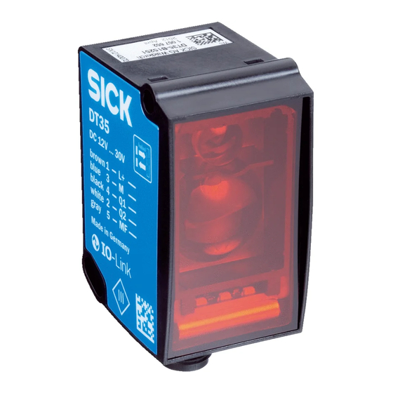
Производитель: SICK
Маркировка: DT35-B15251 | 1057652
Диапазон измерения: 0,05…12 м. Источник излучения: лазер (класс 2), красный. Световое пятно: 15х15 мм. Точность на максимальном расстоянии: ± 10,0 мм. Время отклика: 1/2/4/8/32 мс. Выходной сигнал: 4…20 мA/0…10 В + PNP/NPN. Интерфейс: IO-Link. Температурный диапазон эксплуатации: -30…+55 °C. Питание: 12…30 V DC. Подключение: разъем М12 5 pin.
Лазерный датчик расстояния DT35-B15251 артикул 1057652 от компании SICK на диапазон до 12 м с двумя независимыми выходами: аналоговым 4-20 мА или 0-10 В для непрерывного измерения расстояния и дискретным PNP/NPN для контроля порогового значения расстояния. Настройка осуществляется при помощи кнопок на корпусе, а светодиодные индикаторы облегчают параметрирование. Лазерный датчик расстояния DT35-B15251 применяется в различных задачах по автоматизации производства, где требуется точный и надежный лазерный дальномер с широкими возможностями. Оснащен интерфейсом IO-Link для связи и дополнительных настроек через ПК.
| производитель | номер детали | датащи | подробное описание детали |
|
SICK AG |
DR35-B15822 |
1Mb / 7P |
MID RANGE DISTANCE SENSORS |
| DS50-N1112 |
573Kb / 6P |
MID RANGE DISTANCE SENSORS | |
| DS50-P1112 |
573Kb / 6P |
MID RANGE DISTANCE SENSORS | |
| DT35-B15851 |
1Mb / 8P |
MID RANGE DISTANCE SENSORS | |
| DT50-2B215252 |
1Mb / 9P |
MID RANGE DISTANCE SENSORS | |
| DS30-N2253 |
687Kb / 6P |
MID RANGE DISTANCE SENSORS | |
| DL60-P111B0015 |
608Kb / 7P |
MID RANGE DISTANCE SENSORS | |
| DS40-P21221 |
460Kb / 6P |
MID RANGE DISTANCE SENSORS | |
| DS60-N31111 |
655Kb / 6P |
MID RANGE DISTANCE SENSORS | |
| DS60-N31311 |
655Kb / 6P |
MID RANGE DISTANCE SENSORS | |
| DS60-N51111 |
655Kb / 6P |
MID RANGE DISTANCE SENSORS |
Производитель: SICK
Маркировка: DT35-B15251 | 1057652
Диапазон измерения: 0,05…12 м. Источник излучения: лазер (класс 2), красный. Световое пятно: 15х15 мм. Точность на максимальном расстоянии: ± 10,0 мм. Время отклика: 1/2/4/8/32 мс. Выходной сигнал: 4…20 мA/0…10 В + PNP/NPN. Интерфейс: IO-Link. Температурный диапазон эксплуатации: -30…+55 °C. Питание: 12…30 V DC. Подключение: разъем М12 5 pin.
Лазерный датчик расстояния DT35-B15251 артикул 1057652 от компании SICK на диапазон до 12 м с двумя независимыми выходами: аналоговым 4-20 мА или 0-10 В для непрерывного измерения расстояния и дискретным PNP/NPN для контроля порогового значения расстояния. Настройка осуществляется при помощи кнопок на корпусе, а светодиодные индикаторы облегчают параметрирование. Лазерный датчик расстояния DT35-B15251 применяется в различных задачах по автоматизации производства, где требуется точный и надежный лазерный дальномер с широкими возможностями. Оснащен интерфейсом IO-Link для связи и дополнительных настроек через ПК.