Швейная машина Singer Cosmo 7422 — инструкция пользователя по применению, эксплуатации и установке на русском языке. Мы надеемся, она поможет вам решить возникшие у вас вопросы при эксплуатации техники.
Вы можете скачать инструкцию к Singer Cosmo 7422 по ссылке ниже, если не хотите ждать загрузки. Если остались вопросы, задайте их в комментариях после инструкции.
«Загружаем инструкцию», означает, что нужно подождать пока файл загрузится и можно будет его читать онлайн. Некоторые инструкции очень большие и время их появления зависит от вашей скорости интернета.
Полезные видео
Характеристики
Остались вопросы?
Не нашли свой ответ в руководстве или возникли другие проблемы? Задайте свой вопрос в форме ниже с подробным описанием вашей ситуации, чтобы другие люди и специалисты смогли дать на него ответ. Если вы знаете как решить проблему другого человека, пожалуйста, подскажите ему


Часто задаваемые вопросы

Как посмотреть инструкцию к Singer Cosmo 7422?
Необходимо подождать полной загрузки инструкции в сером окне на данной странице или скачать кликнув по специальной кнопке.
Руководство на русском языке?
Все наши руководства представлены на русском языке или схематично, поэтому вы без труда сможете разобраться с вашей моделью
Как можно распечатать инструкцию?
Скачайте ее по специальной кнопке над формой чтения на ваше устройства и отправьте на печать.
-
Инструкции по эксплуатации
1

Singer 7422, 7442, 7462, 7464, 7466, 7468 инструкция по эксплуатации
(30 страниц)
- Языки:Русский
-
Тип:
PDF -
Размер:
1.69 MB -
Описание:
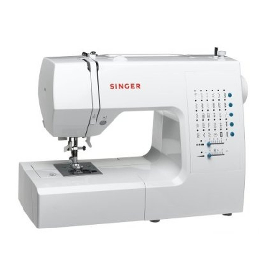
Швейная машина
Просмотр
На NoDevice можно скачать инструкцию по эксплуатации для Singer 7422, 7442, 7462, 7464, 7466, 7468. Руководство пользователя необходимо для ознакомления с правилами установки и эксплуатации Singer 7422, 7442, 7462, 7464, 7466, 7468. Инструкции по использованию помогут правильно настроить Singer 7422, 7442, 7462, 7464, 7466, 7468, исправить ошибки и выявить неполадки.
- Manuals
- Brands
- Singer Manuals
- Sewing Machine
- Advance 7422
- Service manual
-
Contents
-
Table of Contents
-
Bookmarks
Quick Links
SERVICE MANUAL
MODEL 7422/7424/7426/7428
7442/7444/7446/7448
7462/7464/7466/7468
Original issue: April, 2005
Revised :
July,2005
— 1 —
Part No. 77350
Related Manuals for Singer 7422
Summary of Contents for Singer 7422
-
Page 1
SERVICE MANUAL MODEL 7422/7424/7426/7428 7442/7444/7446/7448 7462/7464/7466/7468 Original issue: April, 2005 Part No. 77350 Revised : July,2005 — 1 -… -
Page 2: Table Of Contents
INDEX Sec. 1 Disassembling of covers — — — — — — — — — — — — — — — — — — — — — — 1-6 Sec. 2 Test mode — — — — — — — — — — — — — — — — — — — — — — — — — — — — — — — — 7-9 Sec.
-
Page 3: Sec. 1 Disassembling Of Covers
Sec.1 Disassembling of covers (1) Face cover side Remove screw A.
-
Page 4
Remove two screws F & G. Remove screw H. Loosen screw J with washer. Remove screw K on bottom side. — 4 -… -
Page 5
Remove screw L on bottom side. Remove needle plate by loosening two screws. Push up front cove to open inserting Small screw driver between front and back covers. -
Page 6
Pull out front cover. Open mating portion of front and back covers using small screw driver. Push back cover by small screw driver. -
Page 7
Lift up front cover as illustrated. Lift up front cover as illustrated. Lower presser foot lever to remove back cover easily. — 7 -… -
Page 8
Disassembling of covers for model 7422 An additional bottom cover is provided on model 7422. Remove screws S for front cover and then 5 screws on the bottom cover. Bottom cover Disassembling of covers for model 7424・7426・7428 An additional bottom cover is provided on model 7424, 7426 and 7428. -
Page 9: Sec.2 Test Mode
4. Release bobbin winder while pushing reverse switch, just after power switch is turned on. 5. LED is lit at the top left corner. 7422, 7442, 7424, 7444, 7462 7464 and…
-
Page 10
Note: Above operation is to be done in the following manner. Steps 1 to 3 Steps 4 to 5 Release bobbin winder by the time when LED is lit at extreme right line. -
Page 11
Test mode; Mode 1: In case of model 7422, 7442 and 7462, push switch at top right corner after machine is under test mode as described above, and pattern LED will be lit at top left corner. In case of other models, push pattern switch at top left corner after machine is under test mode and the switch will be lit. -
Page 12: Sec. 3 Adjustment Of Feed Dog Height
Adjustment of feed dog height Sec. 3 Checking: 1. Move feed dog to its highest position by turning hand wheel. Check to see if feed dog height is as illustrated below. 0.9 – 1.0 mm Adjustment: 1.
-
Page 13: Sec. 4 Needle Bar Height
Sec. 4 Needle bar height Note: Make this checking before checking “Needle timing to shuttle” Checking: 1. Remove needle plate and bobbin case. Select straight stitch (center needle position). Raise needle to its highest position by turning hand wheel. 2. Check to see if distance from needle point to the surface of needle plate is as illustrated below.
-
Page 14: Sec. 5 Needle Position At Zigzag Stitching
Sec. 5 Needle position at zigzag stitching Checking: 1. Set test mode at 1. 2. Turn hand wheel by hand and see if needle leaves the same clearance at both right and left end of needle plate hole. a=b Adjustment: 1.
-
Page 15: Sec. 6 Clearance Between Needle And Shuttle
Sec. 6 Clearance between needle and shuttle Note: Make this checking before checking “Needle timing to shuttle” Checking: 1. Remove needle plate, bobbin case and face cover. 2. Set test mode at 1. 3. Shift shuttle hook at the rear of needle by turning hand wheel. Check to see if needle clearance to shuttle is within 0.05 to 0.15 mm.
-
Page 16
2. If needle clearance to shuttle at right and left position is not same, adjust position of fulcrum for needle swing support . Loosen bolt located under bottom of support plate and adjust position of fulcrum. Do not loosen this screw. 3. -
Page 17: Sec. 7 Needle Timing To Feed Dog
Sec. 7 Needle timing to feed dog Note: After adjustment, be sure to follow “Needle timing to shuttle”. Checking: 1. Turning hand wheel, bring needle bar to it’s highest position. 2. Check to see if feed dog starts to move when needle starts to go down by turning hand wheel towards you.
-
Page 18: Sec. 8 Needle Timing To Shuttle Hook
Sec. 8 Needle timing to shuttle hook Check “Needle timing to feed dog” and “Needle bar height” beforehand. Checking: 1. Set mode at 1. 2. Remove needle plate. Check to see if needle is not bent. 3.
-
Page 19: Sec. 9 Needle Stopper At Right Position
Sec. 9 Needle stopper at right position Note: Before checking, follow section “Needle position at zigzag stitching“ Checking: 1. Set test mode at 1. Remove face cover. 2. Bring needle to right position. 3. With needle bar touched with stopper at right side, check to see if needle collides with presser foot and needle plate.
-
Page 20: Sec. 10 Adjustment Of Thread Tension
Sec. 10 Adjustment of thread tension Checking: 1. Set thread tension at the center of “AUTO” position. 2. Pull thread between tension discs and check thread tension value using 100 gr. tension gauge. Measured value should be 40 to 50 g. *When tension gauge is not available, do actual sewing and check balance of upper and lower threads.
-
Page 21: Sec. 11 Zigzag Bight & Stitch Balance
Sec.11 Zigzag bight & stitch balance Zigzag bight Checking meshing position of gears This procedure is needed only when disassembling and re-assembling cams. (1) Checking Remove face cover and turn off power switch. Rotate gear (a) clockwise until it stops with long projection touched with shaft. Check to see if end (c) of zigzag cam (b) aligns with center of gear (a).
-
Page 22
Screw on motor gear Adjustment In case of small deviation from correct zero feed, adjust as follows: *It is recommended to use SINGER test needle when checking Zero feed. 1. Turn off power switch. 2. Loosen one of two screws on motor gear. -
Page 23
<Fine adjustment mechanism is available for stitch length according to models> Fine adjustment is needed for all patterns including buttonholes on models with many stitch patterns except model 7422, 7442 and 7462. Fine adjustment mechanism is provided for this purpose in addition to adjustment of motor gear above. … -
Page 24
Origin point positioning of stitch length In case of large deviation, adjust as follows: Note: There are two stitch length mechanisms – half-step and full-step versions. (A) Stitch length (Half-step version) *Stitch length mechanism on half-step version Step motor rotates 7.5 degrees with one pulse and this amount of rotation makes feed regulator rotate 3 degrees under ratio of 1 : 2.5 of motor gear vs feed regulator gear. -
Page 25
6. Temporarily tighten one screw which is located for easier access for adjustment. 7. Set machine at test mode 2 [Zero feed] again by turning on power switch. 8. A ctivate the origin point positioning of feed motor by turning hand wheel manually. 9. -
Page 26
2. Thread: Coats & Clark #60 3. Presser foot: Satin foot 4. Actual patterns to be checked: 7422, 7424, 7442, 7444, 7462 and 7464 – zigzag stitch with stitch length at 0.25 and smocking stitch 7426, 7446 and 7466 –… -
Page 27
7428, 7448 and 7468 – zigzag stitch with stitch length at 0.25, honeycomb stitch #44 at default position and dog pattern #89. 5. Make fine adjustment to obtain feed balance for each pattern. Use fine adjustment mechanism, if available. 6. Tighten screws on motor gear securely after adjustment. … -
Page 28
Meshing motor gear with feed regulator gear When meshing motor gear with feed regulator gear again, follow procedures below: A. Half-step version Mesh these gears so that centers of feed regulator and motor gear and concave hole may be positioned in alignment … -
Page 29: Sec.12 Needle Stops At Heighest Position
Sec. 12 Needle stop at highest position Needle always stops at its highest position. This is controlled by sensor cam and sensor located on main shaft. Checking: 1. Raise needle to its highest position by turning hand wheel. 2. Push bobbin winder to the right. 3.
-
Page 30: Ac Power Board
Sec. 13 Electronic component area AC Power Board Component number is 87530 for 120V spec. and 87553 for 230V spec. Be sure to check number printed on board. Transformer Secondary 5P Connector cord Connect with CPU LED lamp harness Main motor DC 120v Transformer YM-45D Primary…
-
Page 31: Cpu Board
CPU Board – 1 (for model 7422, 7442 and 7462) Component number for half-step version is 87520 and for full-step version is 87580 Be sure to check number printed on board. Motor for needle zigzag Motor for feed material…
-
Page 32
CPU Board – 2 (other models) Component number for half-step version is 87520 and for full-step version is 87580. Be sure to check number printed on board. Motor for needle zigzag Motor for feed material Not use Cam sensor harness 5P connector cable Bobbin winding switch… -
Page 33: Switch Board
Switch Board – 1 (for model 7422, 7442 and 7462) Component number is 87526. Check number printed on board. 13P Connector Connect with CPU 4P Connector Connect with CPU — 33 -…
-
Page 34
Switch Board – 2 (for 7446, 7466, 7444 and 7464) Component number for 7446 and 7466 is 87547. for 7444 and 7464 is 87533. 87533 is the one where jumper wire is cut on 87547. Component number printed on board is 87547 on both boards. 13P Connector Connect with CPU 4P Connector… -
Page 35
Switch Board – 3 (for 7426 and 7424) Component number for 7426 is 87563 and for 7424 is 87562. 87562 is the one where jumper wire is cut on 87563. Component number printed on board is 87563 on both boards. 13P Connector Connect with CPU 63 … -
Page 36
Switch Board – 4 (for 7428) Component number is 87564. Be sure to check number printed on board. 13P Connector Connect with CPU 64 Twin needle select SW & needle stop select SW 12 Switches 4P Connector Connect with CPU 4P Connector Connect with CPU — 36 -… -
Page 37
Switch Board – 5 (for 7448 and 7468) Component number is 87548. Be sure to check number printed on board. 13P Connector Connect with CPU 4P Connector Connect with CPU 12 Switches 4P Connector Connect with CPU Twin needle Select SW Needle stop position select SW… -
Page 38
Wiring diagram — 38 -… -
Page 39
— 39 -… -
Page 40
— 40 -…